WO2021131288A1 - ポンプ装置 - Google Patents
ポンプ装置 Download PDFInfo
- Publication number
- WO2021131288A1 WO2021131288A1 PCT/JP2020/039852 JP2020039852W WO2021131288A1 WO 2021131288 A1 WO2021131288 A1 WO 2021131288A1 JP 2020039852 W JP2020039852 W JP 2020039852W WO 2021131288 A1 WO2021131288 A1 WO 2021131288A1
- Authority
- WO
- WIPO (PCT)
- Prior art keywords
- pump
- pump device
- main surface
- housing
- adhesive
- Prior art date
- Legal status (The legal status is an assumption and is not a legal conclusion. Google has not performed a legal analysis and makes no representation as to the accuracy of the status listed.)
- Ceased
Links
Images


Classifications
-
- F—MECHANICAL ENGINEERING; LIGHTING; HEATING; WEAPONS; BLASTING
- F04—POSITIVE - DISPLACEMENT MACHINES FOR LIQUIDS; PUMPS FOR LIQUIDS OR ELASTIC FLUIDS
- F04B—POSITIVE-DISPLACEMENT MACHINES FOR LIQUIDS; PUMPS
- F04B43/00—Machines, pumps, or pumping installations having flexible working members
- F04B43/02—Machines, pumps, or pumping installations having flexible working members having plate-like flexible members, e.g. diaphragms
- F04B43/04—Pumps having electric drive
- F04B43/043—Micropumps
- F04B43/046—Micropumps with piezoelectric drive
-
- F—MECHANICAL ENGINEERING; LIGHTING; HEATING; WEAPONS; BLASTING
- F04—POSITIVE - DISPLACEMENT MACHINES FOR LIQUIDS; PUMPS FOR LIQUIDS OR ELASTIC FLUIDS
- F04B—POSITIVE-DISPLACEMENT MACHINES FOR LIQUIDS; PUMPS
- F04B45/00—Pumps or pumping installations having flexible working members and specially adapted for elastic fluids
- F04B45/04—Pumps or pumping installations having flexible working members and specially adapted for elastic fluids having plate-like flexible members, e.g. diaphragms
- F04B45/047—Pumps having electric drive
-
- F—MECHANICAL ENGINEERING; LIGHTING; HEATING; WEAPONS; BLASTING
- F04—POSITIVE - DISPLACEMENT MACHINES FOR LIQUIDS; PUMPS FOR LIQUIDS OR ELASTIC FLUIDS
- F04B—POSITIVE-DISPLACEMENT MACHINES FOR LIQUIDS; PUMPS
- F04B45/00—Pumps or pumping installations having flexible working members and specially adapted for elastic fluids
- F04B45/08—Pumps or pumping installations having flexible working members and specially adapted for elastic fluids having peristaltic action
- F04B45/10—Pumps or pumping installations having flexible working members and specially adapted for elastic fluids having peristaltic action having plate-like flexible members
Definitions
- the present invention relates to a pump device including a pump and an external housing communicating with the pump.
- Patent Document 1 describes a sphygmomanometer using a piezoelectric pump.
- the sphygmomanometer described in Patent Document 1 includes an inner case member.
- the inner case member is made of synthetic resin.
- the inner case and the surface having the discharge port of the piezoelectric pump are adhered.
- the inner case member is made of a resin containing water
- the water inside the resin may volatilize and reach the adhesive surface with the piezoelectric pump.
- the presence of moisture on the adhesive surface with the piezoelectric pump may cause a problem that the adhesive surface is peeled off.
- an object of the present invention is to provide a fluid control device capable of suppressing a decrease in the adhesive state between the housing and the pump even when a housing made of a water-containing material is used.
- the pump device of the present invention includes a pump, an outer housing, and an adhesive member.
- the pump has a discharge surface with a fluid discharge port.
- the outer housing has an internal space communicating with the discharge port, and at least a part of the resin having a water content is used.
- the adhesive member adheres the discharge surface of the pump to the outer housing.
- the outer housing includes a first main plate that faces the discharge surface of the pump and abuts on the adhesive member, and has a through hole that communicates with the discharge port and the internal space.
- the first main surface is made of metal.
- the present invention even if a housing made of a water-containing material is used, it is possible to suppress a decrease in the adhesive state between the housing and the pump.
- FIG. 1 is a cross-sectional view of a side surface showing a configuration of a pump device according to a first embodiment of the present invention.
- FIG. 2 is an exploded perspective view of the pump device according to the first embodiment of the present invention.
- FIG. 3 is a cross-sectional view of a side surface showing a configuration of a pump device according to a second embodiment of the present invention.
- FIG. 4 is a cross-sectional view of a side surface showing a configuration of a pump device according to a third embodiment of the present invention.
- FIG. 5 is a cross-sectional view of a side surface showing a configuration of a pump device according to a fourth embodiment of the present invention.
- FIG. 1 is a cross-sectional view of a side surface showing a configuration of a pump device according to a first embodiment of the present invention.
- FIG. 2 is an exploded perspective view of the pump device according to the first embodiment of the present invention.
- the shape (dimensions) of each component is exaggerated partially or as a whole in order to make the explanation easy to understand.
- the pump device 1 includes a piezoelectric pump 10, an outer housing 70, and an adhesive sheet 80.
- the adhesive sheet 80 corresponds to the "adhesive member" of the present invention.
- the piezoelectric pump 10 and the outer housing 70 are adhered to each other by an adhesive sheet 80.
- the discharge port 41 of the piezoelectric pump 10 and the through hole 710 of the outer housing 70 communicate with each other through the central opening 81 of the adhesive sheet 80.
- the piezoelectric pump 10 includes a piezoelectric element 20, a flat plate member 300 including a diaphragm 31, a first housing member 40, a second housing member 50, and a third housing member 60.
- the piezoelectric element 20 is composed of a disc piezoelectric body and driving electrodes.
- the driving electrodes are formed on both main surfaces of the piezoelectric body of the disk.
- the flat plate member 300 includes a diaphragm 31, a base portion 32, and a support portion 33.
- the flat plate member 300 is, for example, a flat plate made of metal or the like.
- the shape of the flat plate member 300 in a plan view is rectangular. This plane-viewed surface is the main surface of the flat plate member 300.
- the flat plate member 300 is realized by, for example, a single flat plate. That is, the diaphragm 31, the base portion 32, and the support portion 33 are integrally formed by a single flat plate.
- the diaphragm 31 is a disk.
- the base portion 32 has a shape that surrounds the outer circumference of the diaphragm 31.
- the support portion 33 connects the diaphragm 31 and the base portion 32.
- the support portion 33 locally connects the diaphragm 31 and the base portion 32 at a plurality of locations on the outer circumference of the diaphragm 31. With this configuration, the diaphragm 31 is oscillatedly supported by the base portion 32.
- the first housing member 40 is, for example, a flat plate made of metal.
- the material of the first housing member 40 may have a predetermined rigidity.
- the shape of the first housing member 40 in a plan view is substantially rectangular. This plane view is the main surface of the first housing member 40. That is, the first housing member 40 has a main surface 401 and a main surface 402 facing each other.
- the main surface 402 corresponds to the "discharge surface" of the present invention.
- the first housing member 40 has a discharge port 41. Looking at the piezoelectric pump 10 in a plan view, the discharge port 41 overlaps, for example, the center of the diaphragm 31.
- the discharge port 41 is a through hole that penetrates between the main surface 401 and the main surface 402 of the first housing member 40, that is, penetrates the first housing member 40 in the thickness direction.
- the discharge port 41 is, for example, cylindrical.
- the second housing member 50 includes a main plate 51 and a frame body 52, and has a box shape.
- the second housing member 50 is made of, for example, metal or the like.
- the main plate 51 is a flat plate. More specifically, the shape of the main plate 51 in a plan view is rectangular, and has substantially the same area and shape as the first housing member 40.
- the frame body 52 extends in a direction orthogonal to the main surface of the main plate 51.
- the frame body 52 is arranged along the outer peripheral edge of the main plate 51.
- the second housing member 50 is formed in a box shape.
- the main plate 51 and the frame body 52 may be formed separately or integrally molded.
- a plurality of suction ports 510 are formed on the main plate 51.
- the plurality of suction ports 510 are through holes that penetrate both main surfaces of the main plate 51, that is, penetrate the main plate 51 in the thickness direction.
- the plurality of suction ports 510 are cylindrical.
- the third housing member 60 is a frame body having a predetermined thickness.
- the outer shape of the third housing member 60 is substantially the same as the outer shape of the first housing member 40.
- a third housing member 60 is connected to one main surface of the first housing member 40.
- the base portion 32 of the flat plate member 300 is connected to the third housing member 60.
- the frame body 52 of the second housing member 50 is connected to the base portion 32 of the flat plate member 300.
- the space 500 is divided into a space 501 and a space 502 by the diaphragm 31.
- Space 501 is a space on the discharge port 41 side with reference to the diaphragm 31
- space 502 is a space on the suction port 510 side with reference to the diaphragm 31.
- the space 501 and the space 502 communicate with each other by a through hole penetrating the flat plate member 300 provided in the support portion 33.
- the piezoelectric element 20 is arranged on the main surface of the diaphragm 31 on the space 502 side.
- the piezoelectric pump 10 conveys a fluid as shown below. Since the principle of fluid transfer is known from past applications of the applicant of the present application, the description thereof will be simplified.
- the piezoelectric element 20 is connected to a control unit (not shown).
- the control unit generates an AC voltage and applies it to the piezoelectric element 20.
- the piezoelectric element 20 expands and contracts, and the diaphragm 31 bends and vibrates.
- the volumes of the space 501 and the space 502 change, and the fluid is sucked into the piezoelectric pump 10 through the plurality of suction ports 510, and the fluid is sucked into the piezoelectric pump 10 through the discharge port 41 of the piezoelectric pump 10. It is discharged to the outside.
- the outer housing 70 is mainly made of resin.
- resin a material having excellent moldability is used, and for example, polycarbonate or ABS resin is used.
- the outer housing 70 includes a main plate 71 and a side plate 72.
- the main plate 71 has a flat plate shape having a main surface 711.
- the side plate 72 is a frame body.
- the side plate 72 is connected to the main surface 711 of the main plate 71.
- the outer housing 70 is formed, for example, by integrally molding a resin.
- the outer housing 70 has an internal space 720 surrounded by the main plate 71 and the side plates 72.
- the main plate 71 corresponds to the "fixing member” of the present invention.
- the main surface 711 corresponds to the "first main surface” of the present invention.
- the internal space 720 corresponds to the "first space” of the present invention.
- the internal space 720 can be separated from the external housing 70 and the external space by arranging, for example, a flat plate (not shown) connected to the side plate 72 on the opposite side of the internal space 720 from the main plate 71. It becomes.
- the main plate 71 has a housing flow path 700.
- the housing flow path 700 is formed inside the main plate 71.
- the housing flow path 700 corresponds to the "second space" of the present invention.
- the main plate 71 has an external discharge port 701.
- the external discharge port 701 is open on one side surface of the main plate 71 and communicates with the housing flow path 700.
- the main plate 71 has a through hole 710.
- the through hole 710 opens in the main surface 711 and communicates with the housing flow path 700.
- the through hole 710 is, for example, cylindrical.
- the opening cross-sectional area of the through hole 710 is substantially the same as the opening cross-sectional area of the discharge port 41 of the piezoelectric pump 10.
- the main surface 711 of the main plate 71 is made of metal 79. More specifically, it covers substantially the entire main surface 711 of the main plate 71, and a portion having a predetermined depth from the main surface 711 is made of metal 79.
- the metal 79 is realized by a vapor deposition film, a sputter film, plating, or the like.
- the metal 79 contains at least one of aluminum (Al), copper (Cu), iron (Fe), nickel (Ni), chromium (Cr), tin (Zn), titanium (Ti), gold (Au) and the like. It consists of materials.
- the thickness of the metal 79 is, for example, about 10 nm to 1 ⁇ m, but may be larger.
- the adhesive sheet 80 has an annular shape having a predetermined thickness and a circular central opening 81.
- the area of the central opening 81 is larger than the opening cross-sectional area of the discharge port 41 of the piezoelectric pump 10 and the opening cross-sectional area of the through hole 710 of the outer housing 70.
- the diameter of the outer circumference of the adhesive sheet 80 is equal to or less than the length of one side of the first housing member 40 of the piezoelectric pump 10.
- the adhesive sheet 80 is a so-called double-sided adhesive sheet, for example, an acrylic adhesive sheet or a silicon adhesive sheet.
- the adhesive sheet 80 may or may not have an intermediate resin layer.
- One main surface of the adhesive sheet 80 is in contact with and adheres to the main surface 402 of the first housing member 40 of the piezoelectric pump 10.
- the other main surface of the adhesive sheet 80 is in contact with and adheres to the main surface 711 of the main plate 71 in the outer housing 70. As a result, the piezoelectric pump 10 and the outer housing 70 are adhered to each other.
- the adhesive sheet 80 is arranged so that the central opening 81 overlaps the discharge port 41 of the first housing member 40 in the piezoelectric pump 10 and the through hole 710 of the main plate 71 in the outer housing 70.
- the discharge port 41 of the piezoelectric pump 10 and the through hole 710 of the outer housing 70 communicate with each other through the central opening 81 of the adhesive sheet 80.
- the piezoelectric pump 10 having the above configuration generates heat due to the vibration of the diaphragm 31. This heat is transferred to the outer housing 70 via the adhesive sheet 80, and the temperature of the outer housing 70 rises. When the temperature of the outer housing 70 becomes high, the water contained in the resin volatilizes and tends to be released to the outside of the outer housing 70.
- the main surface 711 of the main plate 71 that is, the adhesive surface with the adhesive sheet 80 is metal 79. Since the metal 79 does not allow moisture to permeate, the moisture is not exposed on the main surface 711.
- the moisture on the adhesive surface of the adhesive sheet 80 to the outer housing 70 can be suppressed, and the decrease in the adhesiveness between the main surface 711 and the adhesive sheet 80 is suppressed.
- the area of the main surface 711 is larger than the area of the adhesive sheet 80 (the area of the adhesive surface between the main surface 711 and the adhesive sheet 80).
- the area of the main surface 402 of the first housing member 40 is larger than the area of the adhesive sheet 80 (the area of the adhesive surface between the main surface 402 and the adhesive sheet 80).
- the adhesive sheet 80 is not in contact with or adhered to the corners of the first housing member 40. That is, the adhesive sheet 80 is not in contact with or adhered to the position farthest from the center of vibration in the first housing member 40.
- the leakage of vibration generated by the diaphragm 31 to the outer housing 70 can be suppressed, and the vibration efficiency of the piezoelectric pump 10 can be improved.
- this is not limited to the case where the shape of the piezoelectric pump 10 in a plan view is rectangular, and the same effect can be obtained even in the case of other polygons.
- the adhesive area between the first housing member 40 and the outer housing 70 can be reduced via the adhesive sheet 80. As a result, the amount of heat propagated from the first housing member 40 to the outer housing 70 can be reduced, and the temperature rise of the outer housing 70 can be suppressed.
- the shape of the central opening 81 can be easily maintained when the piezoelectric pump 10 and the outer housing 70 are bonded to each other.
- a thermosetting or UV curable liquid adhesive it is not easy to make the shape of the central opening 81 a predetermined shape, and the discharge port 41 and the through hole 710 It may block the gap. Therefore, by using the configuration of the pump device 1 provided with the adhesive sheet 80, the pump device 1 can be manufactured more reliably and easily.
- the discharge port 41 communicates with the housing flow path 700 of the outer housing 70.
- the suction port 510 communicates with the housing flow path 700 of the outer housing 70.
- the fluid discharged from the discharge port 41 for example, air
- the configuration of the pump device 1 works more effectively.
- the outer housing 70 is made of a resin having a water content, even if the outer housing 70 is made of another material, the above-mentioned effects can be obtained by applying the structure of the present invention. Play.
- the configuration of the present invention works more effectively when the material has a water absorption rate of, for example, 0.15 or more, which is an index of water content.
- the port communicating with the outer housing 70 is used as the discharge port, but it is also possible to use the port on this side as the suction port and the above-mentioned suction port as the discharge port.
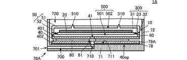
- FIG. 3 is a cross-sectional view of a side surface showing a configuration of a pump device according to a second embodiment of the present invention.
- the pump device 1A according to the second embodiment is different from the pump device 1 according to the first embodiment in that it includes a metal 79A and a metal bonding material 78.
- the other configuration of the pump device 1A is the same as that of the pump device 1, and the description of the same parts will be omitted.
- the outer housing 70A includes a metal 79A and a metal bonding material 78.
- the metal 79A is joined to the main surface 711 of the main plate 71 via a metal bonding material 78.
- the metal 79A has a plate shape and is formed separately from the outer housing 70A.
- the metal bonding material 78 is, for example, a thermosetting or ultraviolet curable bonding material.
- the main surface 711 of the main plate 71 is made of metal 79A. Therefore, the pump device 1A can suppress the moisture on the adhesive surface of the adhesive sheet 80 as in the pump device 1, and the decrease in the adhesiveness between the main surface 711 and the adhesive sheet 80 is suppressed.
- FIG. 4 is a cross-sectional view of a side surface showing a configuration of a pump device according to a third embodiment of the present invention.
- the pump device 1B according to the third embodiment is different from the pump device 1 according to the first embodiment in that the metal 79B is provided.
- the other configurations of the pump device 1B are the same as those of the pump device 1, and the description of the same parts will be omitted.
- the outer housing 70B includes a metal 79B.
- the metal 79B is embedded in the main plate 71 so as to be exposed from the main surface 711 side of the main plate 71.
- the metal 79B has a plate shape, and is embedded in the main plate 71 of the outer housing 70B by using, for example, an insert molding method or the like.
- the main surface 711 of the main plate 71 is made of metal 79B. Therefore, the pump device 1B can suppress the absorption of water into the adhesive sheet 80 like the pump device 1, and the deterioration of the adhesiveness between the main surface 711 and the adhesive sheet 80 is suppressed.
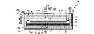
- FIG. 5 is a cross-sectional view of a side surface showing a configuration of a pump device according to a fourth embodiment of the present invention.
- the pump device 1C according to the fourth embodiment is different from the pump device 1 according to the first embodiment in the configuration of the piezoelectric pump 10C.
- the piezoelectric pump 10C further includes a fourth housing member 61 and a fifth housing member 62 with respect to the piezoelectric pump 10. Further, the piezoelectric pump 10C differs from the piezoelectric pump 10 in the arrangement mode of the piezoelectric element 20. Further, the second housing member 50C is configured by combining the sixth housing member 51C and the seventh housing member 52C.
- the fourth housing member 61 is a frame body having a predetermined thickness.
- the outer shape of the fourth housing member 61 is the same as the outer shape of the flat plate member 300.
- the fourth housing member 61 is connected to the other main surface of the flat plate member 300 (the surface opposite to the surface to which the third housing member 60 is connected).
- the fifth housing member 62 has a flat plate shape.
- the planar shape of the fifth housing member 62 is substantially the same as that of the flat plate member 300.
- the fifth housing member 62 has a through hole 620.
- the through hole 620 is arranged substantially in the center of the fifth housing member 62 in a plan view.
- the fifth housing member 62 is arranged on the side opposite to the flat plate member 300 side with reference to the fourth housing member 61.
- the fifth housing member 62 is connected to the fourth housing member 61.
- the sixth housing member 51C is a flat plate.
- the planar shape of the sixth housing member 51C is substantially the same as that of the flat plate member 300 and the fifth housing member 62.
- the sixth housing member 51C is arranged on the side opposite to the flat plate member 300 side with reference to the fifth housing member 62.
- the sixth housing member 51C and the fifth housing member 62 are arranged at predetermined intervals.
- the sixth housing member 51C has a plurality of suction ports 510.
- the plurality of suction ports 510 are arranged at positions separated from the center of the sixth housing member 51C by a predetermined distance on the outer edge side.
- the seventh housing member 52C is a flat plate on which the groove 503 is formed.
- the planar shape of the seventh housing member 52C is substantially the same as that of the fifth housing member 62 and the sixth housing member 51C.
- the seventh housing member 52C is arranged between the fifth housing member 62 and the sixth housing member 51C, and comes into contact with the fifth housing member 62 and the sixth housing member 51C. ,Connecting. Then, in this configuration, the groove 503 communicates with the through hole 620 and the plurality of suction ports 510.
- the piezoelectric element 20 is arranged on the surface of the diaphragm member 300 on the vibration plate 31 side of the first housing member 40.
- the pump device 1C can exert the same action and effect as the pump device 1 described above.
- the outer shape of the adhesive sheet 80 may match the planar shape of the piezoelectric pump 10.
- the outer shape of the adhesive surface to the piezoelectric pump 10 becomes circular, and the center of the diaphragm 31 and the center of the adhesive sheet 80 are made substantially the same, so that the direction of the influence on the vibration of the circular diaphragm 31 ( Difference due to position in the circumferential direction) is suppressed.
- the above configuration is applicable to any pump device using the piezoelectric pump 10, but it is particularly effective in a pump device having a small shape, for example, a wearable pump device.
- a pump device having a small shape the heat capacity of the outer housing is small, so that the temperature can be easily raised. Therefore, the outer housing tends to have a high temperature, and moisture tends to volatilize.
- the configuration of the present invention it is possible to suppress the absorption of water into the adhesive sheet 80, and it is possible to suppress a decrease in the adhesiveness between the outer housing and the adhesive sheet 80.
- Pump device 10C Piezoelectric pump 20: Piezoelectric element 31: Diaphragm 32: Base 33: Support 40: First housing member 41: Discharge port 50: Second housing Member 51: Main plate 52: Side wall 51C: Member for sixth housing 52C: Member for seventh housing 60: Member for third housing 61: Member for fourth housing 62: Member for fifth housing 70, 70A, 70B: Outer housing 71: Main plate 72: Side plate 78: Metal bonding material 79, 79A, 79B: Metal 80: Adhesive sheet 81: Central opening 300: Flat plate member 401, 402: Main surface 500, 501, 502: Space 510: Suction port 700: Housing flow path 701: External discharge port 710: Through hole 711: Main surface 720: Internal space
Landscapes
- Engineering & Computer Science (AREA)
- Mechanical Engineering (AREA)
- General Engineering & Computer Science (AREA)
- Reciprocating Pumps (AREA)
Priority Applications (4)
| Application Number | Priority Date | Filing Date | Title |
|---|---|---|---|
| DE112020005324.5T DE112020005324T5 (de) | 2019-12-26 | 2020-10-23 | Pumpvorrichtung |
| JP2021566859A JP7327514B2 (ja) | 2019-12-26 | 2020-10-23 | ポンプ装置 |
| CN202080083282.XA CN114761686B (zh) | 2019-12-26 | 2020-10-23 | 泵装置 |
| US17/661,774 US12025116B2 (en) | 2019-12-26 | 2022-05-03 | Pump apparatus |
Applications Claiming Priority (2)
| Application Number | Priority Date | Filing Date | Title |
|---|---|---|---|
| JP2019-235444 | 2019-12-26 | ||
| JP2019235444 | 2019-12-26 |
Related Child Applications (1)
| Application Number | Title | Priority Date | Filing Date |
|---|---|---|---|
| US17/661,774 Continuation US12025116B2 (en) | 2019-12-26 | 2022-05-03 | Pump apparatus |
Publications (1)
| Publication Number | Publication Date |
|---|---|
| WO2021131288A1 true WO2021131288A1 (ja) | 2021-07-01 |
Family
ID=76574260
Family Applications (1)
| Application Number | Title | Priority Date | Filing Date |
|---|---|---|---|
| PCT/JP2020/039852 Ceased WO2021131288A1 (ja) | 2019-12-26 | 2020-10-23 | ポンプ装置 |
Country Status (5)
| Country | Link |
|---|---|
| US (1) | US12025116B2 (https=) |
| JP (1) | JP7327514B2 (https=) |
| CN (1) | CN114761686B (https=) |
| DE (1) | DE112020005324T5 (https=) |
| WO (1) | WO2021131288A1 (https=) |
Families Citing this family (4)
| Publication number | Priority date | Publication date | Assignee | Title |
|---|---|---|---|---|
| CN116249834B (zh) * | 2020-09-30 | 2024-06-04 | 株式会社村田制作所 | 流体控制装置 |
| US11978690B2 (en) * | 2021-07-09 | 2024-05-07 | Frore Systems Inc. | Anchor and cavity configuration for MEMS-based cooling systems |
| US12497286B2 (en) | 2021-07-09 | 2025-12-16 | Frore Systems Inc. | Anchor and cavity configuration for MEMS-based cooling systems |
| US12581620B2 (en) | 2021-07-12 | 2026-03-17 | Frore Systems Inc. | Exit channel configuration for MEMS-based actuator systems |
Citations (3)
| Publication number | Priority date | Publication date | Assignee | Title |
|---|---|---|---|---|
| WO2017061349A1 (ja) * | 2015-10-05 | 2017-04-13 | 株式会社村田製作所 | 流体制御装置、減圧装置、および、加圧装置 |
| WO2018021099A1 (ja) * | 2016-07-29 | 2018-02-01 | 株式会社村田製作所 | バルブ、気体制御装置、及び血圧計 |
| WO2019124060A1 (ja) * | 2017-12-22 | 2019-06-27 | 株式会社村田製作所 | ポンプ |
Family Cites Families (10)
| Publication number | Priority date | Publication date | Assignee | Title |
|---|---|---|---|---|
| JP2001323879A (ja) | 2000-05-16 | 2001-11-22 | Matsushita Electric Ind Co Ltd | 圧電ポンプ |
| JP2002314279A (ja) * | 2001-04-19 | 2002-10-25 | Matsushita Electric Ind Co Ltd | 冷却装置 |
| JP5028802B2 (ja) | 2006-01-11 | 2012-09-19 | 日本電気株式会社 | 圧電型液体搬送器 |
| JP5291892B2 (ja) * | 2007-05-01 | 2013-09-18 | オリンパスイメージング株式会社 | 撮像素子モジュール、撮像素子モジュールを用いたレンズユニット及び携帯用電子機器 |
| CN104364526B (zh) * | 2012-06-11 | 2016-08-24 | 株式会社村田制作所 | 鼓风机 |
| JP2016200067A (ja) * | 2015-04-10 | 2016-12-01 | 株式会社村田製作所 | 流体制御装置 |
| JP6849488B2 (ja) | 2017-03-07 | 2021-03-24 | オムロン株式会社 | 血圧計、血圧測定方法および機器 |
| JP6536770B1 (ja) * | 2018-02-16 | 2019-07-03 | 株式会社村田製作所 | 流体制御装置 |
| TWI747076B (zh) * | 2019-11-08 | 2021-11-21 | 研能科技股份有限公司 | 行動裝置散熱組件 |
| JP2023133758A (ja) * | 2022-03-14 | 2023-09-27 | キヤノン株式会社 | 圧電ポンプ、液体吐出ヘッド及び液体吐出装置 |
-
2020
- 2020-10-23 WO PCT/JP2020/039852 patent/WO2021131288A1/ja not_active Ceased
- 2020-10-23 DE DE112020005324.5T patent/DE112020005324T5/de active Pending
- 2020-10-23 CN CN202080083282.XA patent/CN114761686B/zh active Active
- 2020-10-23 JP JP2021566859A patent/JP7327514B2/ja active Active
-
2022
- 2022-05-03 US US17/661,774 patent/US12025116B2/en active Active
Patent Citations (3)
| Publication number | Priority date | Publication date | Assignee | Title |
|---|---|---|---|---|
| WO2017061349A1 (ja) * | 2015-10-05 | 2017-04-13 | 株式会社村田製作所 | 流体制御装置、減圧装置、および、加圧装置 |
| WO2018021099A1 (ja) * | 2016-07-29 | 2018-02-01 | 株式会社村田製作所 | バルブ、気体制御装置、及び血圧計 |
| WO2019124060A1 (ja) * | 2017-12-22 | 2019-06-27 | 株式会社村田製作所 | ポンプ |
Also Published As
| Publication number | Publication date |
|---|---|
| CN114761686A (zh) | 2022-07-15 |
| US12025116B2 (en) | 2024-07-02 |
| US20220260068A1 (en) | 2022-08-18 |
| CN114761686B (zh) | 2024-07-05 |
| JPWO2021131288A1 (https=) | 2021-07-01 |
| JP7327514B2 (ja) | 2023-08-16 |
| DE112020005324T5 (de) | 2022-08-11 |
Similar Documents
| Publication | Publication Date | Title |
|---|---|---|
| WO2021131288A1 (ja) | ポンプ装置 | |
| CN101490419B (zh) | 压电泵 | |
| CN112789407B (zh) | 泵 | |
| US20080038125A1 (en) | Piezoelectric pump and piezoelectric vibrator | |
| JP6111161B2 (ja) | 流体取扱装置および流体取扱方法 | |
| JPWO2021131288A5 (https=) | ||
| US20210277883A1 (en) | Pump | |
| JP7400939B2 (ja) | 流体制御装置 | |
| JP6127361B2 (ja) | 流体制御装置 | |
| JP7485212B2 (ja) | アクチュエータ、ポンプ、アクチュエータの製造方法 | |
| JP2020021068A (ja) | 押さえ環およびレンズモジュール | |
| JP2002106470A (ja) | ダイヤフラムポンプ | |
| JP2010193120A (ja) | シリコンマイクロホン | |
| JP6555214B2 (ja) | 圧力センサ | |
| CN116635632A (zh) | 泵装置 | |
| JP5903306B2 (ja) | 半導体素子の製造方法及びスパッタリング用モジュール | |
| JP2002106468A (ja) | ダイヤフラムポンプ | |
| JP7409518B2 (ja) | 流体制御装置 | |
| JP5003154B2 (ja) | 圧電ポンプ | |
| WO2022070549A1 (ja) | 流体制御装置 | |
| JP7740501B2 (ja) | バルブ、および、流体制御装置 | |
| WO2018230315A1 (ja) | バルブおよび流体制御装置 | |
| JPS59171049A (ja) | 光デイスク | |
| CN114127421B (zh) | 流体控制装置 | |
| JP2002106469A (ja) | ダイヤフラムポンプ |
Legal Events
| Date | Code | Title | Description |
|---|---|---|---|
| 121 | Ep: the epo has been informed by wipo that ep was designated in this application |
Ref document number: 20908389 Country of ref document: EP Kind code of ref document: A1 |
|
| ENP | Entry into the national phase |
Ref document number: 2021566859 Country of ref document: JP Kind code of ref document: A |
|
| 122 | Ep: pct application non-entry in european phase |
Ref document number: 20908389 Country of ref document: EP Kind code of ref document: A1 |