WO2021131288A1 - Pump device - Google Patents
Pump device Download PDFInfo
- Publication number
- WO2021131288A1 WO2021131288A1 PCT/JP2020/039852 JP2020039852W WO2021131288A1 WO 2021131288 A1 WO2021131288 A1 WO 2021131288A1 JP 2020039852 W JP2020039852 W JP 2020039852W WO 2021131288 A1 WO2021131288 A1 WO 2021131288A1
- Authority
- WO
- WIPO (PCT)
- Prior art keywords
- pump
- pump device
- main surface
- housing
- adhesive
- Prior art date
Links
- 239000000853 adhesive Substances 0.000 claims abstract description 81
- 230000001070 adhesive effect Effects 0.000 claims abstract description 81
- 239000002184 metal Substances 0.000 claims abstract description 35
- 229910052751 metal Inorganic materials 0.000 claims abstract description 35
- 229920005989 resin Polymers 0.000 claims abstract description 15
- 239000011347 resin Substances 0.000 claims abstract description 15
- 239000012530 fluid Substances 0.000 claims abstract description 10
- XLYOFNOQVPJJNP-UHFFFAOYSA-N water Substances O XLYOFNOQVPJJNP-UHFFFAOYSA-N 0.000 claims description 15
- 239000000463 material Substances 0.000 claims description 14
- 238000010521 absorption reaction Methods 0.000 claims description 4
- 229920001187 thermosetting polymer Polymers 0.000 claims description 3
- XUIMIQQOPSSXEZ-UHFFFAOYSA-N Silicon Chemical compound [Si] XUIMIQQOPSSXEZ-UHFFFAOYSA-N 0.000 claims description 2
- 239000003522 acrylic cement Substances 0.000 claims description 2
- 238000007747 plating Methods 0.000 claims description 2
- 229910052710 silicon Inorganic materials 0.000 claims description 2
- 239000010703 silicon Substances 0.000 claims description 2
- 230000014759 maintenance of location Effects 0.000 abstract 1
- 230000000694 effects Effects 0.000 description 5
- PXHVJJICTQNCMI-UHFFFAOYSA-N Nickel Chemical compound [Ni] PXHVJJICTQNCMI-UHFFFAOYSA-N 0.000 description 3
- 239000011651 chromium Substances 0.000 description 2
- 239000010949 copper Substances 0.000 description 2
- 239000010931 gold Substances 0.000 description 2
- 238000000465 moulding Methods 0.000 description 2
- 239000010936 titanium Substances 0.000 description 2
- VYZAMTAEIAYCRO-UHFFFAOYSA-N Chromium Chemical compound [Cr] VYZAMTAEIAYCRO-UHFFFAOYSA-N 0.000 description 1
- RYGMFSIKBFXOCR-UHFFFAOYSA-N Copper Chemical compound [Cu] RYGMFSIKBFXOCR-UHFFFAOYSA-N 0.000 description 1
- XEEYBQQBJWHFJM-UHFFFAOYSA-N Iron Chemical compound [Fe] XEEYBQQBJWHFJM-UHFFFAOYSA-N 0.000 description 1
- ATJFFYVFTNAWJD-UHFFFAOYSA-N Tin Chemical compound [Sn] ATJFFYVFTNAWJD-UHFFFAOYSA-N 0.000 description 1
- RTAQQCXQSZGOHL-UHFFFAOYSA-N Titanium Chemical compound [Ti] RTAQQCXQSZGOHL-UHFFFAOYSA-N 0.000 description 1
- 229920000122 acrylonitrile butadiene styrene Polymers 0.000 description 1
- 229910052782 aluminium Inorganic materials 0.000 description 1
- XAGFODPZIPBFFR-UHFFFAOYSA-N aluminium Chemical compound [Al] XAGFODPZIPBFFR-UHFFFAOYSA-N 0.000 description 1
- 229910052804 chromium Inorganic materials 0.000 description 1
- 229910052802 copper Inorganic materials 0.000 description 1
- 230000006866 deterioration Effects 0.000 description 1
- 238000009792 diffusion process Methods 0.000 description 1
- PCHJSUWPFVWCPO-UHFFFAOYSA-N gold Chemical compound [Au] PCHJSUWPFVWCPO-UHFFFAOYSA-N 0.000 description 1
- 229910052737 gold Inorganic materials 0.000 description 1
- 239000007788 liquid Substances 0.000 description 1
- 238000000034 method Methods 0.000 description 1
- 229910052759 nickel Inorganic materials 0.000 description 1
- 230000000149 penetrating effect Effects 0.000 description 1
- 230000002093 peripheral effect Effects 0.000 description 1
- 239000012466 permeate Substances 0.000 description 1
- 239000004417 polycarbonate Substances 0.000 description 1
- 229920005668 polycarbonate resin Polymers 0.000 description 1
- 230000000644 propagated effect Effects 0.000 description 1
- 230000000717 retained effect Effects 0.000 description 1
- 229920003002 synthetic resin Polymers 0.000 description 1
- 239000000057 synthetic resin Substances 0.000 description 1
- 229910052719 titanium Inorganic materials 0.000 description 1
- 238000007740 vapor deposition Methods 0.000 description 1
Images


Classifications
-
- F—MECHANICAL ENGINEERING; LIGHTING; HEATING; WEAPONS; BLASTING
- F04—POSITIVE - DISPLACEMENT MACHINES FOR LIQUIDS; PUMPS FOR LIQUIDS OR ELASTIC FLUIDS
- F04B—POSITIVE-DISPLACEMENT MACHINES FOR LIQUIDS; PUMPS
- F04B43/00—Machines, pumps, or pumping installations having flexible working members
- F04B43/02—Machines, pumps, or pumping installations having flexible working members having plate-like flexible members, e.g. diaphragms
- F04B43/04—Pumps having electric drive
- F04B43/043—Micropumps
- F04B43/046—Micropumps with piezoelectric drive
-
- F—MECHANICAL ENGINEERING; LIGHTING; HEATING; WEAPONS; BLASTING
- F04—POSITIVE - DISPLACEMENT MACHINES FOR LIQUIDS; PUMPS FOR LIQUIDS OR ELASTIC FLUIDS
- F04B—POSITIVE-DISPLACEMENT MACHINES FOR LIQUIDS; PUMPS
- F04B45/00—Pumps or pumping installations having flexible working members and specially adapted for elastic fluids
- F04B45/04—Pumps or pumping installations having flexible working members and specially adapted for elastic fluids having plate-like flexible members, e.g. diaphragms
- F04B45/047—Pumps having electric drive
-
- F—MECHANICAL ENGINEERING; LIGHTING; HEATING; WEAPONS; BLASTING
- F04—POSITIVE - DISPLACEMENT MACHINES FOR LIQUIDS; PUMPS FOR LIQUIDS OR ELASTIC FLUIDS
- F04B—POSITIVE-DISPLACEMENT MACHINES FOR LIQUIDS; PUMPS
- F04B45/00—Pumps or pumping installations having flexible working members and specially adapted for elastic fluids
- F04B45/08—Pumps or pumping installations having flexible working members and specially adapted for elastic fluids having peristaltic action
- F04B45/10—Pumps or pumping installations having flexible working members and specially adapted for elastic fluids having peristaltic action having plate-like flexible members
Abstract
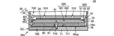
A pump device (1) is provided with a piezoelectric pump (10), an external housing (70), and an adhesive sheet (80). The piezoelectric pump (10) has a main surface (402) including a discharge port (41) for a fluid. The external housing (70) has a housing flow path (700) communicating with the discharge port (41), and a resin having moisture retention properties is used in at least part of said external housing (70). The adhesive sheet (80) bonds the main surface (402) of the piezoelectric pump (10) and the external housing (70). The external housing (70) is provided with a main plate (71) that has a main surface (711) facing the main surface (402) of the piezoelectric pump (10) and in contact with the adhesive sheet (80) and that includes a through hole (710) communicating with the discharge port (41) and the housing flow path (700). The main surface (711) comprises a metal (79).
Description
本発明は、ポンプとポンプに連通する外部筐体とを備えるポンプ装置に関する。
The present invention relates to a pump device including a pump and an external housing communicating with the pump.
特許文献1には、圧電ポンプを用いた血圧計が記載されている。特許文献1に記載の血圧計は、インナーケース部材を備える。インナーケース部材は、合成樹脂からなる。
Patent Document 1 describes a sphygmomanometer using a piezoelectric pump. The sphygmomanometer described in Patent Document 1 includes an inner case member. The inner case member is made of synthetic resin.
インナーケースと圧電ポンプの吐出口を有する面とは、接着されている。
The inner case and the surface having the discharge port of the piezoelectric pump are adhered.
しかしながら、インナーケース部材が、水分を含有する樹脂からなる場合、例えば、インナーケース部材の温度が高くなると、樹脂内部の水分が揮発して、圧電ポンプとの接着面に到達することがある。
However, when the inner case member is made of a resin containing water, for example, when the temperature of the inner case member rises, the water inside the resin may volatilize and reach the adhesive surface with the piezoelectric pump.
そして、圧電ポンプとの接着面に水分が存在することによって、接着面が剥がれるという問題が生じることがある。
Then, the presence of moisture on the adhesive surface with the piezoelectric pump may cause a problem that the adhesive surface is peeled off.
したがって、本発明の目的は、水分含有性を有する材料の筐体を用いても、筐体とポンプとの接着状態の低下を抑制できる流体制御装置を提供することにある。
Therefore, an object of the present invention is to provide a fluid control device capable of suppressing a decrease in the adhesive state between the housing and the pump even when a housing made of a water-containing material is used.
この発明のポンプ装置は、ポンプ、外部筐体、および、接着部材を備える。ポンプは、流体の吐出口を有する吐出面を有する。外部筐体は、吐出口に連通する内部空間を有し、水分含有性を有する樹脂を少なくとも一部に用いる。接着部材は、ポンプの吐出面と外部筐体とを接着する。外部筐体は、ポンプの吐出面に対向し、接着部材に当接する第1主面を有し、吐出口と内部空間とに連通する貫通孔を有する第1主板を備える。第1主面は、金属からなる。
The pump device of the present invention includes a pump, an outer housing, and an adhesive member. The pump has a discharge surface with a fluid discharge port. The outer housing has an internal space communicating with the discharge port, and at least a part of the resin having a water content is used. The adhesive member adheres the discharge surface of the pump to the outer housing. The outer housing includes a first main plate that faces the discharge surface of the pump and abuts on the adhesive member, and has a through hole that communicates with the discharge port and the internal space. The first main surface is made of metal.
この構成では、外部筐体が高温になっても、樹脂に含まれた水分は、金属により第1主面に露出しない。これにより、樹脂に含まれた水分が第1主面と接着部材との接着性に影響を与えない。
With this configuration, even if the outer housing becomes hot, the water contained in the resin is not exposed to the first main surface due to the metal. As a result, the moisture contained in the resin does not affect the adhesiveness between the first main surface and the adhesive member.
この発明によれば、水分含有性を有する材料の筐体を用いても、筐体とポンプとの接着状態の低下を抑制できる。
According to the present invention, even if a housing made of a water-containing material is used, it is possible to suppress a decrease in the adhesive state between the housing and the pump.
(第1実施形態)
本発明の第1の実施形態に係るポンプ装置について、図を参照して説明する。図1は、本発明の第1の実施形態に係るポンプ装置の構成を示す側面の断面図である。図2は、本発明の第1の実施形態に係るポンプ装置の分解斜視図である。なお、本実施形態を含む各実施形態に示す各図においては、説明を分かり易くするために、それぞれの構成要素の形状(寸法)を部分的または全体として誇張して記載している。 (First Embodiment)
The pump device according to the first embodiment of the present invention will be described with reference to the drawings. FIG. 1 is a cross-sectional view of a side surface showing a configuration of a pump device according to a first embodiment of the present invention. FIG. 2 is an exploded perspective view of the pump device according to the first embodiment of the present invention. In addition, in each figure shown in each embodiment including this embodiment, the shape (dimensions) of each component is exaggerated partially or as a whole in order to make the explanation easy to understand.
図1、図2に示すように、ポンプ装置1は、圧電ポンプ10、外部筐体70、および、接着シート80を備える。接着シート80が、本発明の「接着部材」に対応する。圧電ポンプ10と外部筐体70とは、接着シート80によって接着されている。この際、圧電ポンプ10の吐出口41と、外部筐体70の貫通孔710とは、接着シート80の中央開口81を介して、連通する。
As shown in FIGS. 1 and 2, the pump device 1 includes a piezoelectric pump 10, an outer housing 70, and an adhesive sheet 80. The adhesive sheet 80 corresponds to the "adhesive member" of the present invention. The piezoelectric pump 10 and the outer housing 70 are adhered to each other by an adhesive sheet 80. At this time, the discharge port 41 of the piezoelectric pump 10 and the through hole 710 of the outer housing 70 communicate with each other through the central opening 81 of the adhesive sheet 80.
(圧電ポンプ10の構成)
圧電ポンプ10は、圧電素子20、振動板31を含む平板部材300、第1筐体用部材40、第2筐体用部材50、および、第3筐体用部材60を備える。 (Structure of Piezoelectric Pump 10)
Thepiezoelectric pump 10 includes a piezoelectric element 20, a flat plate member 300 including a diaphragm 31, a first housing member 40, a second housing member 50, and a third housing member 60.
圧電ポンプ10は、圧電素子20、振動板31を含む平板部材300、第1筐体用部材40、第2筐体用部材50、および、第3筐体用部材60を備える。 (Structure of Piezoelectric Pump 10)
The
圧電素子20は、円板の圧電体と駆動用の電極とによって構成されている。駆動用の電極は、円板の圧電体の両主面に形成されている。
The piezoelectric element 20 is composed of a disc piezoelectric body and driving electrodes. The driving electrodes are formed on both main surfaces of the piezoelectric body of the disk.
平板部材300は、振動板31、ベース部32、および、支持部33を備えている。平板部材300は、例えば、金属等からなる平板である。平板部材300を平面視した形状は、矩形である。この平面視した面が平板部材300の主面である。平板部材300は、例えば、一枚の平板によって実現される。すなわち、振動板31、ベース部32、および、支持部33は、一枚の平板によって一体形成されている。振動板31は、円板である。ベース部32は、振動板31の外周を囲む形状である。支持部33は、振動板31とベース部32とを接続する。この際、支持部33は、振動板31の外周において、局所的に複数箇所で、振動板31とベース部32とを接続する。この構成によって、振動板31は、ベース部32に対して、振動可能に支持される。
The flat plate member 300 includes a diaphragm 31, a base portion 32, and a support portion 33. The flat plate member 300 is, for example, a flat plate made of metal or the like. The shape of the flat plate member 300 in a plan view is rectangular. This plane-viewed surface is the main surface of the flat plate member 300. The flat plate member 300 is realized by, for example, a single flat plate. That is, the diaphragm 31, the base portion 32, and the support portion 33 are integrally formed by a single flat plate. The diaphragm 31 is a disk. The base portion 32 has a shape that surrounds the outer circumference of the diaphragm 31. The support portion 33 connects the diaphragm 31 and the base portion 32. At this time, the support portion 33 locally connects the diaphragm 31 and the base portion 32 at a plurality of locations on the outer circumference of the diaphragm 31. With this configuration, the diaphragm 31 is oscillatedly supported by the base portion 32.
第1筐体用部材40は、例えば、金属からなる平板である。なお、第1筐体用部材40の材料は、所定の剛性を有してればよい。第1筐体用部材40を平面視した形状は、略矩形である。この平面視した面が、第1筐体用部材40の主面である。すなわち、第1筐体用部材40は、互いに対向する主面401と主面402とを有する。主面402が、本発明の「吐出面」に対応する。
The first housing member 40 is, for example, a flat plate made of metal. The material of the first housing member 40 may have a predetermined rigidity. The shape of the first housing member 40 in a plan view is substantially rectangular. This plane view is the main surface of the first housing member 40. That is, the first housing member 40 has a main surface 401 and a main surface 402 facing each other. The main surface 402 corresponds to the "discharge surface" of the present invention.
第1筐体用部材40は、吐出口41を有する。圧電ポンプ10を平面視して、吐出口41は、例えば、振動板31の中央に重なる。吐出口41は、第1筐体用部材40の主面401と主面402との間を貫く、すなわち、第1筐体用部材40を厚み方向に貫く貫通孔である。吐出口41は、例えば、円筒形である。
The first housing member 40 has a discharge port 41. Looking at the piezoelectric pump 10 in a plan view, the discharge port 41 overlaps, for example, the center of the diaphragm 31. The discharge port 41 is a through hole that penetrates between the main surface 401 and the main surface 402 of the first housing member 40, that is, penetrates the first housing member 40 in the thickness direction. The discharge port 41 is, for example, cylindrical.
第2筐体用部材50は、主板51と枠体52とを備え、箱状である。第2筐体用部材50は、例えば、金属等からなる。主板51は、平板である。より具体的には、主板51を平面視した形状は矩形であり、第1筐体用部材40と略同じ面積および形状である。枠体52は、主板51の主面に直交する方向に延びる。枠体52は、主板51の外周端に沿って配設されている。これにより、第2筐体用部材50は、箱状に形成される。主板51と枠体52とは、別体で形成されていてもよく、一体成型されていてもよい。
The second housing member 50 includes a main plate 51 and a frame body 52, and has a box shape. The second housing member 50 is made of, for example, metal or the like. The main plate 51 is a flat plate. More specifically, the shape of the main plate 51 in a plan view is rectangular, and has substantially the same area and shape as the first housing member 40. The frame body 52 extends in a direction orthogonal to the main surface of the main plate 51. The frame body 52 is arranged along the outer peripheral edge of the main plate 51. As a result, the second housing member 50 is formed in a box shape. The main plate 51 and the frame body 52 may be formed separately or integrally molded.
主板51には、複数の吸入口510が形成されている。複数の吸入口510は、主板51の両主面を貫く、すなわち、主板51を厚み方向に貫く貫通孔である。複数の吸入口510は、円筒形である。
A plurality of suction ports 510 are formed on the main plate 51. The plurality of suction ports 510 are through holes that penetrate both main surfaces of the main plate 51, that is, penetrate the main plate 51 in the thickness direction. The plurality of suction ports 510 are cylindrical.
第3筐体用部材60は、所定の厚みを有する枠体である。第3筐体用部材60の外形は、第1筐体用部材40の外形と略同じである。
The third housing member 60 is a frame body having a predetermined thickness. The outer shape of the third housing member 60 is substantially the same as the outer shape of the first housing member 40.
第1筐体用部材40の一方主面には、第3筐体用部材60が接続する。第3筐体用部材60には、平板部材300のベース部32が接続する。平板部材300のベース部32には、第2筐体用部材50の枠体52が接続する。この構成によって、内部に空間500を有するポンプ筐体が実現される。
A third housing member 60 is connected to one main surface of the first housing member 40. The base portion 32 of the flat plate member 300 is connected to the third housing member 60. The frame body 52 of the second housing member 50 is connected to the base portion 32 of the flat plate member 300. With this configuration, a pump housing having a space 500 inside is realized.
空間500は、振動板31によって、空間501と空間502とに分けられる。空間501は、振動板31を基準にして吐出口41側の空間であり、空間502は、振動板31を基準にして吸入口510側の空間である。空間501と空間502とは、支持部33に設けられた平板部材300を貫通する貫通孔によって連通する。
The space 500 is divided into a space 501 and a space 502 by the diaphragm 31. Space 501 is a space on the discharge port 41 side with reference to the diaphragm 31, and space 502 is a space on the suction port 510 side with reference to the diaphragm 31. The space 501 and the space 502 communicate with each other by a through hole penetrating the flat plate member 300 provided in the support portion 33.
圧電素子20は、振動板31における空間502側の主面に配置されている。
The piezoelectric element 20 is arranged on the main surface of the diaphragm 31 on the space 502 side.
このような構成では、圧電ポンプ10は、次に示すように、流体を搬送する。なお、流体の搬送原理は、本願の出願人の過去の出願等によって既知であるので、説明は簡略化する。
In such a configuration, the piezoelectric pump 10 conveys a fluid as shown below. Since the principle of fluid transfer is known from past applications of the applicant of the present application, the description thereof will be simplified.
圧電素子20は、図示しない制御部に接続されている。制御部は、交流電圧を生成し、圧電素子20に印加する。それによって、圧電素子20が伸縮し、振動板31は、屈曲振動する。これにより、空間501と空間502との体積が変化し、この変化によって、流体は、複数の吸入口510を介して、圧電ポンプ10内に吸入され、吐出口41を介して、圧電ポンプ10の外部に吐出される。
The piezoelectric element 20 is connected to a control unit (not shown). The control unit generates an AC voltage and applies it to the piezoelectric element 20. As a result, the piezoelectric element 20 expands and contracts, and the diaphragm 31 bends and vibrates. As a result, the volumes of the space 501 and the space 502 change, and the fluid is sucked into the piezoelectric pump 10 through the plurality of suction ports 510, and the fluid is sucked into the piezoelectric pump 10 through the discharge port 41 of the piezoelectric pump 10. It is discharged to the outside.
(外部筐体70の構成)
図1および図2に示すように、外部筐体70は、主として、樹脂によって形成されている。樹脂としては、成型性に優れる材料が用いられ、例えば、ポリカーボネートまたはABS樹脂が用いられる。 (Structure of external housing 70)
As shown in FIGS. 1 and 2, theouter housing 70 is mainly made of resin. As the resin, a material having excellent moldability is used, and for example, polycarbonate or ABS resin is used.
図1および図2に示すように、外部筐体70は、主として、樹脂によって形成されている。樹脂としては、成型性に優れる材料が用いられ、例えば、ポリカーボネートまたはABS樹脂が用いられる。 (Structure of external housing 70)
As shown in FIGS. 1 and 2, the
外部筐体70は、主板71および側板72を備える。主板71は、主面711を有する平板状である。側板72は、枠体である。側板72は、主板71の主面711に接続している。外部筐体70は、例えば、樹脂の一体成型によって形成されている。
The outer housing 70 includes a main plate 71 and a side plate 72. The main plate 71 has a flat plate shape having a main surface 711. The side plate 72 is a frame body. The side plate 72 is connected to the main surface 711 of the main plate 71. The outer housing 70 is formed, for example, by integrally molding a resin.
これにより、外部筐体70は、主板71と側板72とによって囲まれる内部空間720を有する。主板71が、本発明の「固定部材」に対応する。主面711が、本発明の「第1主面」に対応する。内部空間720が、本発明の「第1空間」に対応する。そして、この内部空間720に、圧電ポンプ10が固定される。これにより、圧電ポンプ10の外部空間と、外部筐体70の内部空間720とは、連通する。
As a result, the outer housing 70 has an internal space 720 surrounded by the main plate 71 and the side plates 72. The main plate 71 corresponds to the "fixing member" of the present invention. The main surface 711 corresponds to the "first main surface" of the present invention. The internal space 720 corresponds to the "first space" of the present invention. Then, the piezoelectric pump 10 is fixed in the internal space 720. As a result, the external space of the piezoelectric pump 10 and the internal space 720 of the external housing 70 communicate with each other.
なお、内部空間720における主板71と反対側に、側板72に接続する例えば平板(図示を省略する)等が配置されていることで、内部空間720は、外部筐体70と外部空間と隔離可能となる。
The internal space 720 can be separated from the external housing 70 and the external space by arranging, for example, a flat plate (not shown) connected to the side plate 72 on the opposite side of the internal space 720 from the main plate 71. It becomes.
主板71は、筐体流路700を有する。筐体流路700は、主板71の内部に形成されている。筐体流路700が、本発明の「第2空間」に対応する。
The main plate 71 has a housing flow path 700. The housing flow path 700 is formed inside the main plate 71. The housing flow path 700 corresponds to the "second space" of the present invention.
主板71は、外部吐出口701を有する。外部吐出口701は、主板71の一側面に開口しており、筐体流路700に連通する。
The main plate 71 has an external discharge port 701. The external discharge port 701 is open on one side surface of the main plate 71 and communicates with the housing flow path 700.
主板71は、貫通孔710を有する。貫通孔710は、主面711に開口しており、筐体流路700に連通する。貫通孔710は、例えば、円筒形である。貫通孔710の開口断面積は、圧電ポンプ10の吐出口41の開口断面積と略同じである。
The main plate 71 has a through hole 710. The through hole 710 opens in the main surface 711 and communicates with the housing flow path 700. The through hole 710 is, for example, cylindrical. The opening cross-sectional area of the through hole 710 is substantially the same as the opening cross-sectional area of the discharge port 41 of the piezoelectric pump 10.
主板71における主面711は、金属79からなる。より具体的には、主板71における主面711の略全体を覆い、且つ主面711から所定深さの部分が金属79からなる。金属79は、蒸着膜、スパッタ膜、鍍金等によって実現される。金属79は、アルミニウム(Al)、銅(Cu)、鉄(Fe)、ニッケル(Ni)、クロム(Cr)、錫(Zn)、チタン(Ti)、金(Au)等の少なくとも1つを含む材料からなる。金属79の厚みは、例えば、約10nmから1μmであるが、それ以上であってもよい。
The main surface 711 of the main plate 71 is made of metal 79. More specifically, it covers substantially the entire main surface 711 of the main plate 71, and a portion having a predetermined depth from the main surface 711 is made of metal 79. The metal 79 is realized by a vapor deposition film, a sputter film, plating, or the like. The metal 79 contains at least one of aluminum (Al), copper (Cu), iron (Fe), nickel (Ni), chromium (Cr), tin (Zn), titanium (Ti), gold (Au) and the like. It consists of materials. The thickness of the metal 79 is, for example, about 10 nm to 1 μm, but may be larger.
(接着シート80の構成)
図1、図2に示すように、接着シート80は、所定厚みを有し、円形の中央開口81を有する円環形である。中央開口81の面積は、圧電ポンプ10の吐出口41の開口断面積、外部筐体70の貫通孔710の開口断面積よりも大きい。接着シート80の外周の直径は、圧電ポンプ10の第1筐体用部材40の一辺の長さ以下である。 (Structure of Adhesive Sheet 80)
As shown in FIGS. 1 and 2, theadhesive sheet 80 has an annular shape having a predetermined thickness and a circular central opening 81. The area of the central opening 81 is larger than the opening cross-sectional area of the discharge port 41 of the piezoelectric pump 10 and the opening cross-sectional area of the through hole 710 of the outer housing 70. The diameter of the outer circumference of the adhesive sheet 80 is equal to or less than the length of one side of the first housing member 40 of the piezoelectric pump 10.
図1、図2に示すように、接着シート80は、所定厚みを有し、円形の中央開口81を有する円環形である。中央開口81の面積は、圧電ポンプ10の吐出口41の開口断面積、外部筐体70の貫通孔710の開口断面積よりも大きい。接着シート80の外周の直径は、圧電ポンプ10の第1筐体用部材40の一辺の長さ以下である。 (Structure of Adhesive Sheet 80)
As shown in FIGS. 1 and 2, the
接着シート80は、所謂、両面接着シートであり、例えば、アクリル系接着シートまたはシリコン系接着シートである。接着シート80は、中間樹脂層があっても、無くてもよい。
The adhesive sheet 80 is a so-called double-sided adhesive sheet, for example, an acrylic adhesive sheet or a silicon adhesive sheet. The adhesive sheet 80 may or may not have an intermediate resin layer.
(接着シート80による圧電ポンプ10と外部筐体70との接着構成)
接着シート80の一方主面は、圧電ポンプ10における第1筐体用部材40の主面402に当接し、接着している。接着シート80の他方主面は、外部筐体70における主板71の主面711に当接し、接着している。これにより、圧電ポンプ10と外部筐体70とは、接着される。 (Adhesive configuration of thepiezoelectric pump 10 and the outer housing 70 by the adhesive sheet 80)
One main surface of theadhesive sheet 80 is in contact with and adheres to the main surface 402 of the first housing member 40 of the piezoelectric pump 10. The other main surface of the adhesive sheet 80 is in contact with and adheres to the main surface 711 of the main plate 71 in the outer housing 70. As a result, the piezoelectric pump 10 and the outer housing 70 are adhered to each other.
接着シート80の一方主面は、圧電ポンプ10における第1筐体用部材40の主面402に当接し、接着している。接着シート80の他方主面は、外部筐体70における主板71の主面711に当接し、接着している。これにより、圧電ポンプ10と外部筐体70とは、接着される。 (Adhesive configuration of the
One main surface of the
この際、接着シート80は、中央開口81が圧電ポンプ10における第1筐体用部材40の吐出口41、および、外部筐体70における主板71の貫通孔710に重なるように、配置される。これにより、圧電ポンプ10の吐出口41と、外部筐体70の貫通孔710とは、接着シート80の中央開口81を介して連通する。
At this time, the adhesive sheet 80 is arranged so that the central opening 81 overlaps the discharge port 41 of the first housing member 40 in the piezoelectric pump 10 and the through hole 710 of the main plate 71 in the outer housing 70. As a result, the discharge port 41 of the piezoelectric pump 10 and the through hole 710 of the outer housing 70 communicate with each other through the central opening 81 of the adhesive sheet 80.
(ポンプ装置1の構成を用いることによる作用効果)
上述の構成からなる圧電ポンプ10は、振動板31の振動によって発熱する。この熱は、接着シート80を介して、外部筐体70に伝わり、外部筐体70は、昇温する。外部筐体70が高温になると、樹脂に含まれる水分が揮発し、外部筐体70の外部に放出されようとする。 (Effect of action by using the configuration of the pump device 1)
Thepiezoelectric pump 10 having the above configuration generates heat due to the vibration of the diaphragm 31. This heat is transferred to the outer housing 70 via the adhesive sheet 80, and the temperature of the outer housing 70 rises. When the temperature of the outer housing 70 becomes high, the water contained in the resin volatilizes and tends to be released to the outside of the outer housing 70.
上述の構成からなる圧電ポンプ10は、振動板31の振動によって発熱する。この熱は、接着シート80を介して、外部筐体70に伝わり、外部筐体70は、昇温する。外部筐体70が高温になると、樹脂に含まれる水分が揮発し、外部筐体70の外部に放出されようとする。 (Effect of action by using the configuration of the pump device 1)
The
ポンプ装置1の構成では、主板71の主面711、すなわち、接着シート80との接着面が金属79である。金属79は、水分を透過させないので、主面711には、水分は露出しない。
In the configuration of the pump device 1, the main surface 711 of the main plate 71, that is, the adhesive surface with the adhesive sheet 80 is metal 79. Since the metal 79 does not allow moisture to permeate, the moisture is not exposed on the main surface 711.
これにより、接着シート80の外部筐体70への接着面への水分を抑制でき、主面711と接着シート80との接着性の低下は抑制される。
As a result, the moisture on the adhesive surface of the adhesive sheet 80 to the outer housing 70 can be suppressed, and the decrease in the adhesiveness between the main surface 711 and the adhesive sheet 80 is suppressed.
ポンプ装置1の構成では、主面711の面積は、接着シート80の面積(主面711と接着シート80との接着面の面積)よりも大きい。この構成により、外部筐体70における金属79に覆われていない箇所から外部に、水分が漏洩して、接着シート80の接着面に入ることを抑制できる。これにより、主面711と接着シート80との接着性の低下は、さらに抑制される。また、この構成により、主面711による熱拡散効果は、向上し、圧電ポンプ10で発生する熱を、外部に放熱し易い。なお、金属79は、主面711における接着シート80への接着面に少なくとも配置されていればよいが、この理由により、接着面の面積よりも大きいことが好ましい。
In the configuration of the pump device 1, the area of the main surface 711 is larger than the area of the adhesive sheet 80 (the area of the adhesive surface between the main surface 711 and the adhesive sheet 80). With this configuration, it is possible to prevent water from leaking to the outside from a portion of the outer housing 70 that is not covered with the metal 79 and entering the adhesive surface of the adhesive sheet 80. As a result, the decrease in adhesiveness between the main surface 711 and the adhesive sheet 80 is further suppressed. Further, with this configuration, the heat diffusion effect of the main surface 711 is improved, and the heat generated by the piezoelectric pump 10 can be easily dissipated to the outside. The metal 79 may be at least arranged on the adhesive surface of the main surface 711 to the adhesive sheet 80, but for this reason, it is preferably larger than the area of the adhesive surface.
ポンプ装置1の構成では、第1筐体用部材40の主面402の面積は、接着シート80の面積(主面402と接着シート80との接着面の面積)よりも大きい。この構成により、図1に示すように、第1筐体用部材40の角部には、接着シート80が当接、接着していない。すなわち、第1筐体用部材40における振動の中心から最も遠い位置には、接着シート80が当接、接着していない。これにより、振動板31によって生じる振動の外部筐体70への漏洩を抑制でき、圧電ポンプ10の振動効率を向上できる。なお、これは、圧電ポンプ10の平面視した形状が矩形である場合に限らず、他の多角形の場合であっても、同様の作用効果が得られる。また、この構成では、接着シート80を介して、第1筐体用部材40と外部筐体70との接着面積を小さくできる。これにより、第1筐体用部材40から外部筐体70への熱の伝搬量を低下でき、外部筐体70の温度上昇を抑制できる。
In the configuration of the pump device 1, the area of the main surface 402 of the first housing member 40 is larger than the area of the adhesive sheet 80 (the area of the adhesive surface between the main surface 402 and the adhesive sheet 80). With this configuration, as shown in FIG. 1, the adhesive sheet 80 is not in contact with or adhered to the corners of the first housing member 40. That is, the adhesive sheet 80 is not in contact with or adhered to the position farthest from the center of vibration in the first housing member 40. As a result, the leakage of vibration generated by the diaphragm 31 to the outer housing 70 can be suppressed, and the vibration efficiency of the piezoelectric pump 10 can be improved. It should be noted that this is not limited to the case where the shape of the piezoelectric pump 10 in a plan view is rectangular, and the same effect can be obtained even in the case of other polygons. Further, in this configuration, the adhesive area between the first housing member 40 and the outer housing 70 can be reduced via the adhesive sheet 80. As a result, the amount of heat propagated from the first housing member 40 to the outer housing 70 can be reduced, and the temperature rise of the outer housing 70 can be suppressed.
ポンプ装置1の構成では、外形形状が保持された接着シート80を用いることで、圧電ポンプ10と外部筐体70との接着時に、中央開口81の形状を、容易に維持できる。一方、例えば、熱硬化性またはUV硬化性の液状の接着材を用いることは可能であるが、中央開口81の形状を所定形状にすることは容易ではなく、吐出口41と貫通孔710との間を塞いでしまう可能性がある。したがって、接着シート80を備えたポンプ装置1の構成を用いることで、ポンプ装置1を、より確実且つ容易に製造できる。
In the configuration of the pump device 1, by using the adhesive sheet 80 whose outer shape is retained, the shape of the central opening 81 can be easily maintained when the piezoelectric pump 10 and the outer housing 70 are bonded to each other. On the other hand, for example, although it is possible to use a thermosetting or UV curable liquid adhesive, it is not easy to make the shape of the central opening 81 a predetermined shape, and the discharge port 41 and the through hole 710 It may block the gap. Therefore, by using the configuration of the pump device 1 provided with the adhesive sheet 80, the pump device 1 can be manufactured more reliably and easily.
また、この構成では、圧電ポンプ10の吐出口41に、外部に突出するノズルを形成しなくてもよい。これにより、ポンプ装置1は、薄型になる。
Further, in this configuration, it is not necessary to form a nozzle protruding to the outside at the discharge port 41 of the piezoelectric pump 10. As a result, the pump device 1 becomes thin.
また、このポンプ装置1では、吐出口41が外部筐体70の筐体流路700に連通している。一方、上述の構成を適用すれば、吸入口510が外部筐体70の筐体流路700に連通する構成も実現可能である。しかしながら、吐出口41から吐出される流体(例えば、空気)は、吸入口510から吸入される流体よりも高温になる。このため、吐出口41が外部筐体70の筐体流路700に連通する構造において、ポンプ装置1の構成は、より有効に作用する。
Further, in this pump device 1, the discharge port 41 communicates with the housing flow path 700 of the outer housing 70. On the other hand, if the above configuration is applied, it is possible to realize a configuration in which the suction port 510 communicates with the housing flow path 700 of the outer housing 70. However, the fluid discharged from the discharge port 41 (for example, air) has a higher temperature than the fluid sucked from the suction port 510. Therefore, in the structure in which the discharge port 41 communicates with the housing flow path 700 of the outer housing 70, the configuration of the pump device 1 works more effectively.
なお、外部筐体70が、水分含有性を有する樹脂で構成されていれば、外部筐体70は、他の材料であっても、本発明の構成を適用することで、上述の作用効果を奏する。特に、水分含有性の一指標である吸水率が例えば0.15以上の材料の場合に、本発明の構成は、より有効に作用する。
If the outer housing 70 is made of a resin having a water content, even if the outer housing 70 is made of another material, the above-mentioned effects can be obtained by applying the structure of the present invention. Play. In particular, the configuration of the present invention works more effectively when the material has a water absorption rate of, for example, 0.15 or more, which is an index of water content.
また、上述の説明では、外部筐体70に連通する口を吐出口としたが、こちら側の口を吸入口として、上述の吸入口を吐出口として用いることも可能である。
Further, in the above description, the port communicating with the outer housing 70 is used as the discharge port, but it is also possible to use the port on this side as the suction port and the above-mentioned suction port as the discharge port.
(第2実施形態)
本発明の第2の実施形態に係るポンプ装置について、図を参照して説明する。図3は、本発明の第2の実施形態に係るポンプ装置の構成を示す側面の断面図である。 (Second Embodiment)
The pump device according to the second embodiment of the present invention will be described with reference to the drawings. FIG. 3 is a cross-sectional view of a side surface showing a configuration of a pump device according to a second embodiment of the present invention.
図3に示すように、第2の実施形態に係るポンプ装置1Aは、第1の実施形態に係るポンプ装置1に対して、金属79A、および、金属用接合材78を備える点で異なる。ポンプ装置1Aの他の構成は、ポンプ装置1と同様であり、同様の箇所の説明は省略する。
As shown in FIG. 3, the pump device 1A according to the second embodiment is different from the pump device 1 according to the first embodiment in that it includes a metal 79A and a metal bonding material 78. The other configuration of the pump device 1A is the same as that of the pump device 1, and the description of the same parts will be omitted.
外部筐体70Aは、金属79A、および、金属用接合材78を備える。金属79Aは、主板71の主面711に、金属用接合材78を介して接合される。
The outer housing 70A includes a metal 79A and a metal bonding material 78. The metal 79A is joined to the main surface 711 of the main plate 71 via a metal bonding material 78.
金属79Aは、板状であり、外部筐体70Aと別体で形成されたものである。金属用接合材78は、例えば、熱硬化性または紫外線硬化性の接合材である。
The metal 79A has a plate shape and is formed separately from the outer housing 70A. The metal bonding material 78 is, for example, a thermosetting or ultraviolet curable bonding material.
この構成により、主板71の主面711は、金属79Aからなる。したがって、ポンプ装置1Aは、ポンプ装置1と同様に、接着シート80の接着面への水分を抑制でき、主面711と接着シート80との接着性の低下は抑制される。
With this configuration, the main surface 711 of the main plate 71 is made of metal 79A. Therefore, the pump device 1A can suppress the moisture on the adhesive surface of the adhesive sheet 80 as in the pump device 1, and the decrease in the adhesiveness between the main surface 711 and the adhesive sheet 80 is suppressed.
(第3実施形態)
本発明の第3の実施形態に係るポンプ装置について、図を参照して説明する。図4は、本発明の第3の実施形態に係るポンプ装置の構成を示す側面の断面図である。 (Third Embodiment)
The pump device according to the third embodiment of the present invention will be described with reference to the drawings. FIG. 4 is a cross-sectional view of a side surface showing a configuration of a pump device according to a third embodiment of the present invention.
図4に示すように、第3の実施形態に係るポンプ装置1Bは、第1の実施形態に係るポンプ装置1に対して、金属79Bを備える点で異なる。ポンプ装置1Bの他の構成は、ポンプ装置1と同様であり、同様の箇所の説明は省略する。
As shown in FIG. 4, the pump device 1B according to the third embodiment is different from the pump device 1 according to the first embodiment in that the metal 79B is provided. The other configurations of the pump device 1B are the same as those of the pump device 1, and the description of the same parts will be omitted.
外部筐体70Bは、金属79Bを備える。金属79Bは、主板71の主面711側から露出するように、主板71に埋め込まれている。
The outer housing 70B includes a metal 79B. The metal 79B is embedded in the main plate 71 so as to be exposed from the main surface 711 side of the main plate 71.
金属79Bは、板状であり、例えば、インサートモールド工法等を用いて、外部筐体70Bの主板71に埋め込まれる。
The metal 79B has a plate shape, and is embedded in the main plate 71 of the outer housing 70B by using, for example, an insert molding method or the like.
この構成により、主板71の主面711は、金属79Bからなる。したがって、ポンプ装置1Bは、ポンプ装置1と同様に、接着シート80に水分が吸収されることを抑制でき、主面711と接着シート80との接着性の低下は抑制される。
With this configuration, the main surface 711 of the main plate 71 is made of metal 79B. Therefore, the pump device 1B can suppress the absorption of water into the adhesive sheet 80 like the pump device 1, and the deterioration of the adhesiveness between the main surface 711 and the adhesive sheet 80 is suppressed.
(第4実施形態)
本発明の第4の実施形態に係るポンプ装置について、図を参照して説明する。図5は、本発明の第4の実施形態に係るポンプ装置の構成を示す側面の断面図である。 (Fourth Embodiment)
The pump device according to the fourth embodiment of the present invention will be described with reference to the drawings. FIG. 5 is a cross-sectional view of a side surface showing a configuration of a pump device according to a fourth embodiment of the present invention.
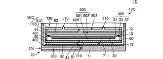
図5に示すように、第4の実施形態に係るポンプ装置1Cは、第1の実施形態に係るポンプ装置1に対して、圧電ポンプ10Cの構成において異なる。
As shown in FIG. 5, the pump device 1C according to the fourth embodiment is different from the pump device 1 according to the first embodiment in the configuration of the piezoelectric pump 10C.
圧電ポンプ10Cは、圧電ポンプ10に対して、第4筐体用部材61、第5筐体用部材62をさらに備える。また、圧電ポンプ10Cは、圧電ポンプ10に対して、圧電素子20の配置態様において異なる。また、第2筐体用部材50Cは、第6筐体用部材51Cと第7筐体用部材52Cとを組み合わせることによって構成される。
The piezoelectric pump 10C further includes a fourth housing member 61 and a fifth housing member 62 with respect to the piezoelectric pump 10. Further, the piezoelectric pump 10C differs from the piezoelectric pump 10 in the arrangement mode of the piezoelectric element 20. Further, the second housing member 50C is configured by combining the sixth housing member 51C and the seventh housing member 52C.
第4筐体用部材61は、所定の厚みを有する枠体である。第4筐体用部材61の外形は、平板部材300の外形と同じ形状である。第4筐体用部材61は、平板部材300の他方主面(第3筐体用部材60が接続する面と反対側の面)に接続する。
The fourth housing member 61 is a frame body having a predetermined thickness. The outer shape of the fourth housing member 61 is the same as the outer shape of the flat plate member 300. The fourth housing member 61 is connected to the other main surface of the flat plate member 300 (the surface opposite to the surface to which the third housing member 60 is connected).
第5筐体用部材62は、平板状である。第5筐体用部材62の平面形状は、平板部材300と略同じである。第5筐体用部材62は、貫通孔620を有する。貫通孔620は、第5筐体用部材62を平面視した略中央に配置されている。
The fifth housing member 62 has a flat plate shape. The planar shape of the fifth housing member 62 is substantially the same as that of the flat plate member 300. The fifth housing member 62 has a through hole 620. The through hole 620 is arranged substantially in the center of the fifth housing member 62 in a plan view.
第5筐体用部材62は、第4筐体用部材61を基準にして、平板部材300側と反対側に配置されている。第5筐体用部材62は、第4筐体用部材61に接続する。
The fifth housing member 62 is arranged on the side opposite to the flat plate member 300 side with reference to the fourth housing member 61. The fifth housing member 62 is connected to the fourth housing member 61.
第6筐体用部材51Cは、平板である。第6筐体用部材51Cの平面形状は、平板部材300および第5筐体用部材62と略同じである。第6筐体用部材51Cは、第5筐体用部材62を基準にして、平板部材300側と反対側に配置されている。第6筐体用部材51Cと第5筐体用部材62とは、所定間隔で離間して配置されている。第6筐体用部材51Cは、複数の吸入口510を有する。複数の吸入口510は、第6筐体用部材51Cの中心から所定距離、外縁側に離間した位置に配置されている。
The sixth housing member 51C is a flat plate. The planar shape of the sixth housing member 51C is substantially the same as that of the flat plate member 300 and the fifth housing member 62. The sixth housing member 51C is arranged on the side opposite to the flat plate member 300 side with reference to the fifth housing member 62. The sixth housing member 51C and the fifth housing member 62 are arranged at predetermined intervals. The sixth housing member 51C has a plurality of suction ports 510. The plurality of suction ports 510 are arranged at positions separated from the center of the sixth housing member 51C by a predetermined distance on the outer edge side.
第7筐体用部材52Cは、溝503が形成された平板である。第7筐体用部材52Cの平面形状は、第5筐体用部材62および第6筐体用部材51Cと略同じである。第7筐体用部材52Cは、第5筐体用部材62と第6筐体用部材51Cとの間に配置され、第5筐体用部材62と第6筐体用部材51Cとに当接、接続する。そして、この構成において、溝503は、貫通孔620および複数の吸入口510に連通する。
The seventh housing member 52C is a flat plate on which the groove 503 is formed. The planar shape of the seventh housing member 52C is substantially the same as that of the fifth housing member 62 and the sixth housing member 51C. The seventh housing member 52C is arranged between the fifth housing member 62 and the sixth housing member 51C, and comes into contact with the fifth housing member 62 and the sixth housing member 51C. ,Connecting. Then, in this configuration, the groove 503 communicates with the through hole 620 and the plurality of suction ports 510.
圧電素子20は、平板部材300の振動板31における第1筐体用部材40側の面に配置されている。
The piezoelectric element 20 is arranged on the surface of the diaphragm member 300 on the vibration plate 31 side of the first housing member 40.
このような構成の圧電ポンプ10Cを用いても、ポンプ装置1Cは、上述のポンプ装置1と同様の作用効果を奏することができる。
Even if the piezoelectric pump 10C having such a configuration is used, the pump device 1C can exert the same action and effect as the pump device 1 described above.
なお、上述の実施形態では、接着シート80を円環形にする態様を示したが、他の形状であってもよい。例えば、接着シート80の外形形状は、圧電ポンプ10の平面形状に合わせてもよい。しかしながら、円環形にすることで、接着シート80の設置時の方向を考慮しなくてもよく、容易に設置できる。さらに、圧電ポンプ10への接着面の外形形状が円形になり、振動板31の中心と接着シート80の中心を略同じにすることで、円形の振動板31の振動に与える影響の方向性(周方向の位置による差)が抑制される。
Although the above-described embodiment shows an embodiment in which the adhesive sheet 80 has a ring shape, other shapes may be used. For example, the outer shape of the adhesive sheet 80 may match the planar shape of the piezoelectric pump 10. However, by forming the adhesive sheet 80 into a ring shape, it is not necessary to consider the direction in which the adhesive sheet 80 is installed, and the adhesive sheet 80 can be easily installed. Further, the outer shape of the adhesive surface to the piezoelectric pump 10 becomes circular, and the center of the diaphragm 31 and the center of the adhesive sheet 80 are made substantially the same, so that the direction of the influence on the vibration of the circular diaphragm 31 ( Difference due to position in the circumferential direction) is suppressed.
また、上述の構成は、圧電ポンプ10を用いるポンプ装置であれば適用可能であるが、特に、形状が小さなポンプ装置、例えば、ウェアラブルなポンプ装置において、より有効である。形状が小さなポンプ装置の場合、外部筐体の熱容量が小さくなるので、昇温し易い。したがって、外部筐体は高温になりやすく、水分が揮発し易い。しかしながら、本発明の構成を備えることによって、接着シート80に水分が吸収されることを抑制でき、外部筐体と接着シート80との接着性の低下は抑制できる。
Further, the above configuration is applicable to any pump device using the piezoelectric pump 10, but it is particularly effective in a pump device having a small shape, for example, a wearable pump device. In the case of a pump device having a small shape, the heat capacity of the outer housing is small, so that the temperature can be easily raised. Therefore, the outer housing tends to have a high temperature, and moisture tends to volatilize. However, by providing the configuration of the present invention, it is possible to suppress the absorption of water into the adhesive sheet 80, and it is possible to suppress a decrease in the adhesiveness between the outer housing and the adhesive sheet 80.
1、1A、1B、1C:ポンプ装置
10、10C:圧電ポンプ
20:圧電素子
31:振動板
32:ベース部
33:支持部
40:第1筐体用部材
41:吐出口
50:第2筐体用部材
51:主板
52:側壁
51C:第6筐体用部材
52C:第7筐体用部材
60:第3筐体用部材
61:第4筐体用部材
62:第5筐体用部材
70、70A、70B:外部筐体
71:主板
72:側板
78:金属用接合材
79、79A、79B:金属
80:接着シート
81:中央開口
300:平板部材
401、402:主面
500、501、502:空間
510:吸入口
700:筐体流路
701:外部吐出口
710:貫通孔
711:主面
720:内部空間 1, 1A, 1B, 1C: Pump device 10, 10C: Piezoelectric pump 20: Piezoelectric element 31: Diaphragm 32: Base 33: Support 40: First housing member 41: Discharge port 50: Second housing Member 51: Main plate 52: Side wall 51C: Member for sixth housing 52C: Member for seventh housing 60: Member for third housing 61: Member for fourth housing 62: Member for fifth housing 70, 70A, 70B: Outer housing 71: Main plate 72: Side plate 78: Metal bonding material 79, 79A, 79B: Metal 80: Adhesive sheet 81: Central opening 300: Flat plate member 401, 402: Main surface 500, 501, 502: Space 510: Suction port 700: Housing flow path 701: External discharge port 710: Through hole 711: Main surface 720: Internal space
10、10C:圧電ポンプ
20:圧電素子
31:振動板
32:ベース部
33:支持部
40:第1筐体用部材
41:吐出口
50:第2筐体用部材
51:主板
52:側壁
51C:第6筐体用部材
52C:第7筐体用部材
60:第3筐体用部材
61:第4筐体用部材
62:第5筐体用部材
70、70A、70B:外部筐体
71:主板
72:側板
78:金属用接合材
79、79A、79B:金属
80:接着シート
81:中央開口
300:平板部材
401、402:主面
500、501、502:空間
510:吸入口
700:筐体流路
701:外部吐出口
710:貫通孔
711:主面
720:内部空間 1, 1A, 1B, 1C:
Claims (9)
- 流体の吐出口を有する吐出面を有するポンプと、
前記吐出口を介して前記ポンプの外部空間に連通し、前記ポンプを備える第1空間を有し、水分含有性を有する樹脂を少なくとも一部に用いた、前記ポンプを固定する固定部材と、
前記ポンプの前記吐出面と前記固定部材とを接着する接着部材と、
を備え、
前記固定部材は、
前記ポンプの前記吐出面に対向し、前記接着部材に当接する第1主面を有し、前記吐出口および前記第1空間と前記固定部材を挟んで前記第1空間と反対側に位置する第2空間とを連通する貫通孔を有する第1主板を備え、
前記第1主面は、金属からなる、
ポンプ装置。 A pump with a discharge surface with a fluid discharge port and
A fixing member for fixing the pump, which communicates with the external space of the pump through the discharge port, has a first space provided with the pump, and uses at least a part of a resin having a water content.
An adhesive member that adheres the discharge surface of the pump and the fixing member,
With
The fixing member is
A first main surface facing the discharge surface of the pump and abutting the adhesive member, and located on the opposite side of the discharge port and the first space and the fixing member from the first space. A first main plate having a through hole that communicates with two spaces is provided.
The first main surface is made of metal.
Pump device. - 前記第1主面は、前記金属の蒸着膜、スパッタ膜、または、鍍金によって形成されている、
請求項1に記載のポンプ装置。 The first main surface is formed of a vapor-deposited film, a sputtered film, or a plating of the metal.
The pump device according to claim 1. - 前記第1主面は、前記第1主板にモールドされた前記金属の板によって形成されている、
請求項1に記載のポンプ装置。 The first main surface is formed by the metal plate molded on the first main plate.
The pump device according to claim 1. - 前記第1主面は、熱硬化性または紫外線硬化性の接合材によって前記第1主板に接合された前記金属の板によって形成されている、
請求項1に記載のポンプ装置。 The first main surface is formed by the metal plate bonded to the first main plate by a thermosetting or ultraviolet curable bonding material.
The pump device according to claim 1. - 前記第1主面の面積は、前記接着部材と前記吐出面の接着面積、および、前記接着部材と前記第1主面との接着面積のいずれよりも大きい、
請求項1乃至請求項4のいずれかに記載のポンプ装置。 The area of the first main surface is larger than any of the adhesive area between the adhesive member and the discharge surface and the adhesive area between the adhesive member and the first main surface.
The pump device according to any one of claims 1 to 4. - 前記吐出面の面積は、前記接着部材と前記吐出面および前記第1主面との接着面積よりも大きい、
請求項1乃至請求項5のいずれかに記載のポンプ装置。 The area of the discharge surface is larger than the adhesive area of the adhesive member, the discharge surface, and the first main surface.
The pump device according to any one of claims 1 to 5. - 前記吐出面は、平面視において多角形であり、
前記接着部材は、前記多角形の角部に接着していない、
請求項6に記載のポンプ装置。 The discharge surface is polygonal in a plan view.
The adhesive member is not adhered to the corner of the polygon.
The pump device according to claim 6. - 前記接着部材は、アクリル系接着シートまたはシリコン系接着シートである、
請求項1乃至請求項7のいずれかに記載のポンプ装置。 The adhesive member is an acrylic adhesive sheet or a silicon adhesive sheet.
The pump device according to any one of claims 1 to 7. - 前記固定部材に用いられる樹脂は、0.15以上の吸水率を有する樹脂である、
請求項1乃至請求項8のいずれかに記載のポンプ装置。 The resin used for the fixing member is a resin having a water absorption rate of 0.15 or more.
The pump device according to any one of claims 1 to 8.
Priority Applications (4)
| Application Number | Priority Date | Filing Date | Title |
|---|---|---|---|
| DE112020005324.5T DE112020005324T5 (en) | 2019-12-26 | 2020-10-23 | pumping device |
| CN202080083282.XA CN114761686A (en) | 2019-12-26 | 2020-10-23 | Pump device |
| JP2021566859A JP7327514B2 (en) | 2019-12-26 | 2020-10-23 | pumping equipment |
| US17/661,774 US20220260068A1 (en) | 2019-12-26 | 2022-05-03 | Pump apparatus |
Applications Claiming Priority (2)
| Application Number | Priority Date | Filing Date | Title |
|---|---|---|---|
| JP2019-235444 | 2019-12-26 | ||
| JP2019235444 | 2019-12-26 |
Related Child Applications (1)
| Application Number | Title | Priority Date | Filing Date |
|---|---|---|---|
| US17/661,774 Continuation US20220260068A1 (en) | 2019-12-26 | 2022-05-03 | Pump apparatus |
Publications (1)
| Publication Number | Publication Date |
|---|---|
| WO2021131288A1 true WO2021131288A1 (en) | 2021-07-01 |
Family
ID=76574260
Family Applications (1)
| Application Number | Title | Priority Date | Filing Date |
|---|---|---|---|
| PCT/JP2020/039852 WO2021131288A1 (en) | 2019-12-26 | 2020-10-23 | Pump device |
Country Status (5)
| Country | Link |
|---|---|
| US (1) | US20220260068A1 (en) |
| JP (1) | JP7327514B2 (en) |
| CN (1) | CN114761686A (en) |
| DE (1) | DE112020005324T5 (en) |
| WO (1) | WO2021131288A1 (en) |
Citations (3)
| Publication number | Priority date | Publication date | Assignee | Title |
|---|---|---|---|---|
| WO2017061349A1 (en) * | 2015-10-05 | 2017-04-13 | 株式会社村田製作所 | Fluid control device, pressure reduction device, and pressure device |
| WO2018021099A1 (en) * | 2016-07-29 | 2018-02-01 | 株式会社村田製作所 | Valve, gas control device, and sphygmomanometer |
| WO2019124060A1 (en) * | 2017-12-22 | 2019-06-27 | 株式会社村田製作所 | Pump |
Family Cites Families (8)
| Publication number | Priority date | Publication date | Assignee | Title |
|---|---|---|---|---|
| JP2002314279A (en) * | 2001-04-19 | 2002-10-25 | Matsushita Electric Ind Co Ltd | Cooling equipment |
| JP5291892B2 (en) * | 2007-05-01 | 2013-09-18 | オリンパスイメージング株式会社 | Imaging device module, lens unit using imaging device module, and portable electronic device |
| WO2013187271A1 (en) * | 2012-06-11 | 2013-12-19 | 株式会社村田製作所 | Blower |
| JP2016200067A (en) * | 2015-04-10 | 2016-12-01 | 株式会社村田製作所 | Fluid control device |
| JP6849488B2 (en) | 2017-03-07 | 2021-03-24 | オムロン株式会社 | Sphygmomanometer, blood pressure measurement method and equipment |
| JP6536770B1 (en) * | 2018-02-16 | 2019-07-03 | 株式会社村田製作所 | Fluid control device |
| TWI747076B (en) * | 2019-11-08 | 2021-11-21 | 研能科技股份有限公司 | Heat dissipating component for mobile device |
| JP2023133758A (en) * | 2022-03-14 | 2023-09-27 | キヤノン株式会社 | Piezoelectric pump, liquid discharge head and liquid discharge device |
-
2020
- 2020-10-23 CN CN202080083282.XA patent/CN114761686A/en active Pending
- 2020-10-23 WO PCT/JP2020/039852 patent/WO2021131288A1/en active Application Filing
- 2020-10-23 JP JP2021566859A patent/JP7327514B2/en active Active
- 2020-10-23 DE DE112020005324.5T patent/DE112020005324T5/en active Pending
-
2022
- 2022-05-03 US US17/661,774 patent/US20220260068A1/en active Pending
Patent Citations (3)
| Publication number | Priority date | Publication date | Assignee | Title |
|---|---|---|---|---|
| WO2017061349A1 (en) * | 2015-10-05 | 2017-04-13 | 株式会社村田製作所 | Fluid control device, pressure reduction device, and pressure device |
| WO2018021099A1 (en) * | 2016-07-29 | 2018-02-01 | 株式会社村田製作所 | Valve, gas control device, and sphygmomanometer |
| WO2019124060A1 (en) * | 2017-12-22 | 2019-06-27 | 株式会社村田製作所 | Pump |
Also Published As
| Publication number | Publication date |
|---|---|
| DE112020005324T5 (en) | 2022-08-11 |
| JP7327514B2 (en) | 2023-08-16 |
| CN114761686A (en) | 2022-07-15 |
| JPWO2021131288A1 (en) | 2021-07-01 |
| US20220260068A1 (en) | 2022-08-18 |
Similar Documents
| Publication | Publication Date | Title |
|---|---|---|
| JP2016053371A (en) | Fluid control device and pump | |
| JPWO2008069264A1 (en) | Piezoelectric pump | |
| CN112789407B (en) | Pump and method of operating the same | |
| JP6726166B2 (en) | Pump unit and manufacturing method thereof | |
| WO2007111049A1 (en) | Micropump | |
| JP6111161B2 (en) | Fluid handling apparatus and fluid handling method | |
| WO2007108246A1 (en) | Piezoelectric micropump | |
| WO2021131288A1 (en) | Pump device | |
| JP2005188355A (en) | Diaphragm pump | |
| JP2002106470A (en) | Diaphragm pump | |
| JP5003154B2 (en) | Piezoelectric pump | |
| JP4061893B2 (en) | Magnet holder | |
| JP2010193120A (en) | Silicon microphone | |
| WO2018037753A1 (en) | Pressure sensor | |
| JP5903306B2 (en) | Semiconductor device manufacturing method and sputtering module | |
| WO2018230315A1 (en) | Valve and fluid control device | |
| WO2022230677A1 (en) | Actuator, pump, and method for manufacturing actuator | |
| JP7485212B2 (en) | Actuator, pump, and method for manufacturing actuator | |
| JP7400939B2 (en) | fluid control device | |
| JP2009293507A (en) | Piezoelectric pump | |
| US11879449B2 (en) | Piezoelectric pump with vibrating plate, protrusion and valve arrangement | |
| JPWO2021131288A5 (en) | ||
| JPS59171049A (en) | Optical disc | |
| WO2021106301A1 (en) | Actuator and fluid control device | |
| JP2002106469A (en) | Diaphragm pump |
Legal Events
| Date | Code | Title | Description |
|---|---|---|---|
| 121 | Ep: the epo has been informed by wipo that ep was designated in this application |
Ref document number: 20908389 Country of ref document: EP Kind code of ref document: A1 |
|
| ENP | Entry into the national phase |
Ref document number: 2021566859 Country of ref document: JP Kind code of ref document: A |
|
| 122 | Ep: pct application non-entry in european phase |
Ref document number: 20908389 Country of ref document: EP Kind code of ref document: A1 |