WO2021131162A1 - 軟磁性鋼板、該軟磁性鋼板の製造方法、該軟磁性鋼板を用いた鉄心および回転電機 - Google Patents
軟磁性鋼板、該軟磁性鋼板の製造方法、該軟磁性鋼板を用いた鉄心および回転電機 Download PDFInfo
- Publication number
- WO2021131162A1 WO2021131162A1 PCT/JP2020/032669 JP2020032669W WO2021131162A1 WO 2021131162 A1 WO2021131162 A1 WO 2021131162A1 JP 2020032669 W JP2020032669 W JP 2020032669W WO 2021131162 A1 WO2021131162 A1 WO 2021131162A1
- Authority
- WO
- WIPO (PCT)
- Prior art keywords
- phase
- soft magnetic
- magnetic steel
- steel sheet
- nitrogen
- Prior art date
- Legal status (The legal status is an assumption and is not a legal conclusion. Google has not performed a legal analysis and makes no representation as to the accuracy of the status listed.)
- Ceased
Links
Images
Classifications
-
- C—CHEMISTRY; METALLURGY
- C21—METALLURGY OF IRON
- C21D—MODIFYING THE PHYSICAL STRUCTURE OF FERROUS METALS; GENERAL DEVICES FOR HEAT TREATMENT OF FERROUS OR NON-FERROUS METALS OR ALLOYS; MAKING METAL MALLEABLE, e.g. BY DECARBURISATION OR TEMPERING
- C21D9/00—Heat treatment, e.g. annealing, hardening, quenching or tempering, adapted for particular articles; Furnaces therefor
- C21D9/46—Heat treatment, e.g. annealing, hardening, quenching or tempering, adapted for particular articles; Furnaces therefor for sheet metals
-
- H—ELECTRICITY
- H01—ELECTRIC ELEMENTS
- H01F—MAGNETS; INDUCTANCES; TRANSFORMERS; SELECTION OF MATERIALS FOR THEIR MAGNETIC PROPERTIES
- H01F1/00—Magnets or magnetic bodies characterised by the magnetic materials therefor; Selection of materials for their magnetic properties
- H01F1/01—Magnets or magnetic bodies characterised by the magnetic materials therefor; Selection of materials for their magnetic properties of inorganic materials
- H01F1/03—Magnets or magnetic bodies characterised by the magnetic materials therefor; Selection of materials for their magnetic properties of inorganic materials characterised by their coercivity
- H01F1/12—Magnets or magnetic bodies characterised by the magnetic materials therefor; Selection of materials for their magnetic properties of inorganic materials characterised by their coercivity of soft-magnetic materials
- H01F1/14—Magnets or magnetic bodies characterised by the magnetic materials therefor; Selection of materials for their magnetic properties of inorganic materials characterised by their coercivity of soft-magnetic materials metals or alloys
- H01F1/16—Magnets or magnetic bodies characterised by the magnetic materials therefor; Selection of materials for their magnetic properties of inorganic materials characterised by their coercivity of soft-magnetic materials metals or alloys in the form of sheets
-
- B—PERFORMING OPERATIONS; TRANSPORTING
- B32—LAYERED PRODUCTS
- B32B—LAYERED PRODUCTS, i.e. PRODUCTS BUILT-UP OF STRATA OF FLAT OR NON-FLAT, e.g. CELLULAR OR HONEYCOMB, FORM
- B32B15/00—Layered products comprising a layer of metal
- B32B15/01—Layered products comprising a layer of metal all layers being exclusively metallic
- B32B15/011—Layered products comprising a layer of metal all layers being exclusively metallic all layers being formed of iron alloys or steels
-
- C—CHEMISTRY; METALLURGY
- C21—METALLURGY OF IRON
- C21D—MODIFYING THE PHYSICAL STRUCTURE OF FERROUS METALS; GENERAL DEVICES FOR HEAT TREATMENT OF FERROUS OR NON-FERROUS METALS OR ALLOYS; MAKING METAL MALLEABLE, e.g. BY DECARBURISATION OR TEMPERING
- C21D1/00—General methods or devices for heat treatment, e.g. annealing, hardening, quenching or tempering
- C21D1/04—General methods or devices for heat treatment, e.g. annealing, hardening, quenching or tempering with simultaneous application of supersonic waves, magnetic or electric fields
-
- C—CHEMISTRY; METALLURGY
- C21—METALLURGY OF IRON
- C21D—MODIFYING THE PHYSICAL STRUCTURE OF FERROUS METALS; GENERAL DEVICES FOR HEAT TREATMENT OF FERROUS OR NON-FERROUS METALS OR ALLOYS; MAKING METAL MALLEABLE, e.g. BY DECARBURISATION OR TEMPERING
- C21D1/00—General methods or devices for heat treatment, e.g. annealing, hardening, quenching or tempering
- C21D1/26—Methods of annealing
-
- C—CHEMISTRY; METALLURGY
- C21—METALLURGY OF IRON
- C21D—MODIFYING THE PHYSICAL STRUCTURE OF FERROUS METALS; GENERAL DEVICES FOR HEAT TREATMENT OF FERROUS OR NON-FERROUS METALS OR ALLOYS; MAKING METAL MALLEABLE, e.g. BY DECARBURISATION OR TEMPERING
- C21D1/00—General methods or devices for heat treatment, e.g. annealing, hardening, quenching or tempering
- C21D1/74—Methods of treatment in inert gas, controlled atmosphere, vacuum or pulverulent material
- C21D1/76—Adjusting the composition of the atmosphere
-
- C—CHEMISTRY; METALLURGY
- C21—METALLURGY OF IRON
- C21D—MODIFYING THE PHYSICAL STRUCTURE OF FERROUS METALS; GENERAL DEVICES FOR HEAT TREATMENT OF FERROUS OR NON-FERROUS METALS OR ALLOYS; MAKING METAL MALLEABLE, e.g. BY DECARBURISATION OR TEMPERING
- C21D6/00—Heat treatment of ferrous alloys
- C21D6/04—Hardening by cooling below 0 degrees Celsius
-
- C—CHEMISTRY; METALLURGY
- C21—METALLURGY OF IRON
- C21D—MODIFYING THE PHYSICAL STRUCTURE OF FERROUS METALS; GENERAL DEVICES FOR HEAT TREATMENT OF FERROUS OR NON-FERROUS METALS OR ALLOYS; MAKING METAL MALLEABLE, e.g. BY DECARBURISATION OR TEMPERING
- C21D8/00—Modifying the physical properties by deformation combined with, or followed by, heat treatment
- C21D8/12—Modifying the physical properties by deformation combined with, or followed by, heat treatment during manufacturing of articles with special electromagnetic properties
- C21D8/1244—Modifying the physical properties by deformation combined with, or followed by, heat treatment during manufacturing of articles with special electromagnetic properties the heat treatment(s) being of interest
- C21D8/1255—Modifying the physical properties by deformation combined with, or followed by, heat treatment during manufacturing of articles with special electromagnetic properties the heat treatment(s) being of interest with diffusion of elements, e.g. decarburising, nitriding
-
- C—CHEMISTRY; METALLURGY
- C22—METALLURGY; FERROUS OR NON-FERROUS ALLOYS; TREATMENT OF ALLOYS OR NON-FERROUS METALS
- C22C—ALLOYS
- C22C38/00—Ferrous alloys, e.g. steel alloys
-
- C—CHEMISTRY; METALLURGY
- C22—METALLURGY; FERROUS OR NON-FERROUS ALLOYS; TREATMENT OF ALLOYS OR NON-FERROUS METALS
- C22C—ALLOYS
- C22C38/00—Ferrous alloys, e.g. steel alloys
- C22C38/001—Ferrous alloys, e.g. steel alloys containing N
-
- C—CHEMISTRY; METALLURGY
- C22—METALLURGY; FERROUS OR NON-FERROUS ALLOYS; TREATMENT OF ALLOYS OR NON-FERROUS METALS
- C22C—ALLOYS
- C22C38/00—Ferrous alloys, e.g. steel alloys
- C22C38/02—Ferrous alloys, e.g. steel alloys containing silicon
-
- C—CHEMISTRY; METALLURGY
- C23—COATING METALLIC MATERIAL; COATING MATERIAL WITH METALLIC MATERIAL; CHEMICAL SURFACE TREATMENT; DIFFUSION TREATMENT OF METALLIC MATERIAL; COATING BY VACUUM EVAPORATION, BY SPUTTERING, BY ION IMPLANTATION OR BY CHEMICAL VAPOUR DEPOSITION, IN GENERAL; INHIBITING CORROSION OF METALLIC MATERIAL OR INCRUSTATION IN GENERAL
- C23C—COATING METALLIC MATERIAL; COATING MATERIAL WITH METALLIC MATERIAL; SURFACE TREATMENT OF METALLIC MATERIAL BY DIFFUSION INTO THE SURFACE, BY CHEMICAL CONVERSION OR SUBSTITUTION; COATING BY VACUUM EVAPORATION, BY SPUTTERING, BY ION IMPLANTATION OR BY CHEMICAL VAPOUR DEPOSITION, IN GENERAL
- C23C8/00—Solid state diffusion of only non-metal elements into metallic material surfaces; Chemical surface treatment of metallic material by reaction of the surface with a reactive gas, leaving reaction products of surface material in the coating, e.g. conversion coatings, passivation of metals
- C23C8/06—Solid state diffusion of only non-metal elements into metallic material surfaces; Chemical surface treatment of metallic material by reaction of the surface with a reactive gas, leaving reaction products of surface material in the coating, e.g. conversion coatings, passivation of metals using gases
- C23C8/08—Solid state diffusion of only non-metal elements into metallic material surfaces; Chemical surface treatment of metallic material by reaction of the surface with a reactive gas, leaving reaction products of surface material in the coating, e.g. conversion coatings, passivation of metals using gases only one element being applied
- C23C8/24—Nitriding
- C23C8/26—Nitriding of ferrous surfaces
-
- C—CHEMISTRY; METALLURGY
- C23—COATING METALLIC MATERIAL; COATING MATERIAL WITH METALLIC MATERIAL; CHEMICAL SURFACE TREATMENT; DIFFUSION TREATMENT OF METALLIC MATERIAL; COATING BY VACUUM EVAPORATION, BY SPUTTERING, BY ION IMPLANTATION OR BY CHEMICAL VAPOUR DEPOSITION, IN GENERAL; INHIBITING CORROSION OF METALLIC MATERIAL OR INCRUSTATION IN GENERAL
- C23C—COATING METALLIC MATERIAL; COATING MATERIAL WITH METALLIC MATERIAL; SURFACE TREATMENT OF METALLIC MATERIAL BY DIFFUSION INTO THE SURFACE, BY CHEMICAL CONVERSION OR SUBSTITUTION; COATING BY VACUUM EVAPORATION, BY SPUTTERING, BY ION IMPLANTATION OR BY CHEMICAL VAPOUR DEPOSITION, IN GENERAL
- C23C8/00—Solid state diffusion of only non-metal elements into metallic material surfaces; Chemical surface treatment of metallic material by reaction of the surface with a reactive gas, leaving reaction products of surface material in the coating, e.g. conversion coatings, passivation of metals
- C23C8/80—After-treatment
-
- H—ELECTRICITY
- H01—ELECTRIC ELEMENTS
- H01F—MAGNETS; INDUCTANCES; TRANSFORMERS; SELECTION OF MATERIALS FOR THEIR MAGNETIC PROPERTIES
- H01F1/00—Magnets or magnetic bodies characterised by the magnetic materials therefor; Selection of materials for their magnetic properties
- H01F1/01—Magnets or magnetic bodies characterised by the magnetic materials therefor; Selection of materials for their magnetic properties of inorganic materials
- H01F1/03—Magnets or magnetic bodies characterised by the magnetic materials therefor; Selection of materials for their magnetic properties of inorganic materials characterised by their coercivity
- H01F1/12—Magnets or magnetic bodies characterised by the magnetic materials therefor; Selection of materials for their magnetic properties of inorganic materials characterised by their coercivity of soft-magnetic materials
- H01F1/14—Magnets or magnetic bodies characterised by the magnetic materials therefor; Selection of materials for their magnetic properties of inorganic materials characterised by their coercivity of soft-magnetic materials metals or alloys
- H01F1/147—Alloys characterised by their composition
-
- H—ELECTRICITY
- H02—GENERATION; CONVERSION OR DISTRIBUTION OF ELECTRIC POWER
- H02K—DYNAMO-ELECTRIC MACHINES
- H02K1/00—Details of the magnetic circuit
- H02K1/02—Details of the magnetic circuit characterised by the magnetic material
-
- H—ELECTRICITY
- H02—GENERATION; CONVERSION OR DISTRIBUTION OF ELECTRIC POWER
- H02K—DYNAMO-ELECTRIC MACHINES
- H02K15/00—Processes or apparatus specially adapted for manufacturing, assembling, maintaining or repairing of dynamo-electric machines
- H02K15/02—Processes or apparatus specially adapted for manufacturing, assembling, maintaining or repairing of dynamo-electric machines of stator or rotor bodies
- H02K15/021—Magnetic cores
Definitions
- the present invention relates to a technique for magnetic materials, and more particularly to an iron-nitrogen soft magnetic steel sheet having a higher saturation magnetic flux density than pure iron, a method for manufacturing the soft magnetic steel sheet, an iron core using the soft magnetic steel sheet, and a rotary electric machine. Is.
- Bs 2.14T
- Patent Document 1 JP 2001-176715
- ⁇ -Fe phase and a mixed phase of Fe 16 N 2 phase as the main phase
- the rate of formation of Fe 16 N 2 phase in ⁇ phase 10% or more 90% The following highly saturated magnetized Fe-N magnetic materials have been reported.
- Patent Document 1 as a method for producing the Fe-N-based magnetic material, iron oxide powder or metallic iron powder (particle size 10 to 50 nm) whose surface is covered with a thin oxide film is reduced in a hydrogen gas stream.
- An example is a production method including a step and a nitriding step of nitriding the iron powder obtained in the reduction step in an ammonia stream or a mixed gas stream containing ammonia gas.
- Patent Document 2 Japanese Patent Laid-Open No. 2015-507354 describes a method for producing a regular martensite iron nitride ( ⁇ ”-Fe 16 N 2 ) powder, and a) an iron alloy powder having a desired composition and uniformity (a). The step of making a particle size of 10 to 20 ⁇ m), b) the step of bringing the iron alloy powder into contact with a nitrogen source in a fluidized bed reactor to nitrid the iron alloy powder to make an iron nitride powder, and c) the above.
- the step of transferring the iron nitride powder to the irregular martensite phase d) the step of baking the irregular martensite phase into the ordered martensite phase, and e) converting the ordered martensite phase into the iron nitride powder.
- a method for producing a ordered martensite iron nitride powder which comprises the step of obtaining the ordered martensite iron nitride powder by separation from the above, has been reported.
- Patent Documents 1 and 2 are suitable for manufacturing and using a thin sheet material such as an electromagnetic steel sheet. I can't say. In other words, a method of exhibiting desirable magnetic properties in a thin plate material such as an electromagnetic steel plate and producing such a thin plate material cannot be known from Patent Documents 1 and 2.
- an object of the present invention is to provide an iron-nitrogen-based soft magnetic steel sheet having a higher Bs than pure iron, a method for producing the soft magnetic steel sheet, an iron core using the soft magnetic steel sheet, and a rotary electric machine.
- One aspect of the present invention is a soft magnetic steel plate. Contains carbon and nitrogen, with the balance consisting of iron and unavoidable impurities Consists of ⁇ phase, ⁇ 'phase, ⁇ 'phase and ⁇ phase
- the ⁇ phase is the main phase
- the volume fraction of the ⁇ "phase is 10% or more
- the volume fraction is 10% or more.
- Provided is a soft magnetic steel sheet, characterized in that the volume fraction of the ⁇ phase is 5% or less.
- the present invention can make the following improvements and modifications to the soft magnetic steel sheet (I) according to the present invention.
- the total concentration of the carbon and the nitrogen is 0.01 atomic% or more and 10 atomic% or less, and the nitrogen concentration is higher than the carbon concentration.
- the ⁇ "phase is a crystal phase in which the ratio “c / a” of the c-axis length to the a-axis length of the lattice constant is different from that of Fe 16 N 2 having a stoichiometric composition.
- the concentration of the carbon is 1.2 atomic% or less, and the concentration of the nitrogen is 9 atomic% or less.
- the saturation magnetic flux density Bs of the soft magnetic steel sheet is more than 2.14 T.
- the thickness of the soft magnetic steel sheet is 0.03 mm or more and 1 mm or less.
- Another aspect of the present invention is the above-mentioned method for producing a soft magnetic steel sheet.
- a starting material consisting of a low carbon steel plate with a carbon concentration of 0.25% by mass or less or an electromagnetic pure iron plate with a carbon concentration of 0.03% by mass or less
- the nitrogen-taining treatment step of cooling to a predetermined temperature by a predetermined cooling method is performed.
- An iron nitride phase generation step in which the starting material that has undergone the nitrogen nitriding treatment step is tempered in a temperature range of 100 ° C. or higher and 210 ° C. or lower to form the ⁇ 'phase and the ⁇ 'phase iron nitride phases.
- the present invention provides a method for producing a soft magnetic steel sheet, which is characterized by having.
- the present invention can be improved or modified as follows in the above-mentioned method (II) for manufacturing a soft magnetic steel sheet according to the present invention.
- the predetermined temperature in the nitrogen-containing heat treatment is a tempering temperature of 100 ° C. or higher and 210 ° C. or lower.
- the predetermined temperature in the nitrogen-containing heat treatment is less than 100 ° C., and the predetermined cooling method is quenching.
- the starting material that has undergone the nitrogen-containing treatment step is further subjected to a subzero treatment of cooling to 0 ° C. or lower.
- a stress field and / or an electromagnetic field is applied to the plate to be heat-treated.
- Yet another aspect of the present invention is the above-mentioned method for producing a soft magnetic steel sheet.
- a starting material consisting of a low carbon steel plate with a carbon concentration of 0.25% by mass or less or an electromagnetic pure iron plate with a carbon concentration of 0.03% by mass or less
- N atoms in a temperature range of 500 ° C. or higher and lower than 592 ° C. and a predetermined ammonia gas atmosphere.
- the nitrogen-containing treatment step of quenching and cooling to a temperature of less than 100 ° C.
- An iron nitride phase generation step in which the starting material that has undergone the nitrogen nitriding treatment step is tempered in a temperature range of 100 ° C. or higher and 210 ° C. or lower to form the ⁇ 'phase and the ⁇ 'phase iron nitride phases.
- the present invention provides a method for producing a soft magnetic steel sheet, which is characterized by having.
- the present invention can be improved or modified as follows in the above-mentioned method (III) for manufacturing a soft magnetic steel sheet according to the present invention.
- (X) Between the nitrogen-containing treatment step and the iron nitride phase formation step, the starting material that has undergone the nitrogen-containing treatment step is further subjected to a subzero treatment of cooling to 0 ° C. or lower.
- (Xi) When performing the nitrogen-containing heat treatment and / or the tempering heat treatment, a stress field and / or an electromagnetic field is applied to the plate to be heat-treated.
- Yet another aspect of the present invention is an iron core made of a laminated body of soft magnetic steel sheets.
- the present invention provides an iron core, characterized in that the soft magnetic steel plate is the soft magnetic steel plate according to the present invention.
- FIG. 1 Yet another aspect of the present invention is a rotary electric machine provided with an iron core.
- a rotary electric machine characterized in that the iron core is the iron core according to the present invention.
- an iron-nitrogen-based soft magnetic steel sheet having a higher saturation magnetic flux density than pure iron and a method for producing the soft magnetic steel sheet. Further, by using the soft magnetic steel plate, it is possible to provide an iron core and a rotary electric machine having higher conversion efficiency between electric energy and magnetic energy than an iron core using pure iron.
- FIG. 1 It is a perspective schematic diagram which shows an example of the stator of a rotary electric machine. It is an enlarged cross-sectional schematic diagram of the slot area of a stator. It is a schematic diagram which shows the structural example of the apparatus for manufacturing the soft magnetic steel sheet of this invention.
- the electromagnetic steel sheet is usually a thin plate material (for example, a thickness of 0.03 to 1 mm), and is a material used as an iron core of a rotary electric machine or a transformer by laminating and molding a plurality of sheets.
- the iron core it is important that the conversion efficiency between electric energy and magnetic energy is high, and high magnetic flux density and low iron loss are important.
- the saturation magnetic flux density Bs is high in order to increase the magnetic flux density, and it is desirable that the coercive force Hc is small and the thin plate workability is good in order to reduce the iron loss.
- cost reduction of the iron core is one of the important issues.
- Pure iron is inexpensive and has a high saturation magnetic flux density (2.14 T).
- the iron loss of pure iron is Hc (80 A / m).
- Fe-Si steel sheet with 1 to 3% by mass of silicon (Si) added to pure iron has a slightly lower saturation magnetic flux density than pure iron (2.0 T), but it is inexpensive and greatly reduces the coercive force. Can be done.
- the Fe-Co-based steel sheet in which Co is mixed in an amount of about 50% by mass shows a sufficiently higher saturation magnetic flux density (2.4 T) and a lower coercive force than pure iron, but the material cost is high as described above.
- the present inventors stably produce Fe-N-based soft magnetic steel sheets by using inexpensive starting materials (for example, low carbon steel sheets and electromagnetic pure iron sheets) with the use as electromagnetic steel sheets in mind. I studied the process diligently. As a result, when the starting material is subjected to a predetermined nitrogen-containing heat treatment to control the N concentration to be higher than the C concentration of the starting material, and then the predetermined nitride phase formation tempering treatment is performed, the ⁇ phase is mainly produced. After making the phase, the volume fraction of the ⁇ "phase can be set to 10% or more and the volume fraction of the ⁇ phase can be set to 5% or less. It has been found that it can be manufactured. The present invention has been completed based on this finding.
- the soft magnetic steel sheet of the present invention contains C and N, and the balance consists of Fe and unavoidable impurities.
- ⁇ phase (ferrite phase, cubic crystal), ⁇ 'phase (irregular martensite phase, Fe 8 N phase, square crystal).
- ⁇ "phase (regular martensite phase, Fe 16 N 2 phase, square crystal) and ⁇ phase (austenite phase, cubic crystal), with ⁇ phase as the main phase and ⁇ " phase volume ratio.
- the volume fraction of the ⁇ "phase is more preferably 15% or more, and the volume fraction of the ⁇ phase is more preferably 3% or less.
- the main phase means the phase having the largest volume fraction.
- the volume fraction of the ⁇ 'phase is not particularly limited, but the volume fraction of the ⁇ 'phase is preferably 10% or more because the ⁇ 'phase may be formed as a preliminary step to the formation of the ⁇ 'phase. ..
- volume fraction of the ⁇ "phase is less than 10%, it becomes difficult for the Bs of the soft magnetic steel sheet to exceed the Bs (2.14 T) of pure iron.
- the ⁇ phase is close to non-magnetic, the ⁇ phase When the volume fraction of is more than 5%, it becomes difficult for the Bs of the soft magnetic steel sheet to exceed the Bs of pure iron, coupled with the reduction of the volume fraction of the ⁇ phase.
- the total concentration of C and N is 0.01 atomic% or more and 10 atomic% or less, and the N concentration is higher than the C concentration.
- the N concentration is more preferably twice or more the C concentration, and further preferably three times or more the C concentration.
- the N concentration is preferably 9 atomic% or less, and the C concentration is preferably 1.2 atomic% or less (0.25% by mass or less).
- the volume fraction of the ⁇ phase does not reach 10%, and it becomes difficult for the Bs of the soft magnetic steel sheet to exceed the Bs of pure iron.
- the volume fraction of the ⁇ phase exceeds 5%, so that it becomes difficult for the Bs of the soft magnetic steel sheet to exceed the Bs of pure iron.
- impurities contained in the starting material such as hydrogen (H), boron (B), Si, phosphorus (P), sulfur (S), chromium (Cr), manganese (Mn), nickel (Ni)) , Copper (Cu), etc.
- H hydrogen
- B boron
- Si silicon
- P sulfur
- S chromium
- Mn manganese
- Ni nickel
- Cu Copper
- the lattice constant of the ⁇ -Fe phase in the Fe-C phase diagram and the lattice constant of the ⁇ -Fe phase It is considered that the lattice constant is different from the lattice constant of the ⁇ -Fe phase in the Fe-N phase diagram. This leads to the ⁇ -phase crystal lattice of the soft magnetic steel sheet being distorted on average. Similar to the above, since the crystal lattice is distorted in the ⁇ phase, an increase in magnetization can be expected as compared with the undistorted crystal lattice.
- the present invention exhibits a magnetic property of Bs (more than 2.14 T) exceeding pure iron and a coercive force Hc (for example, 80 A / m or less) equal to or less than that of pure iron.
- a nitrogen-based soft magnetic steel sheet can be provided.
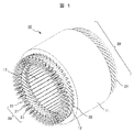
- FIG. 1 is a schematic perspective view showing an example of a stator of a rotary electric machine
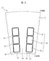
- FIG. 2 is a schematic cross-sectional view of an enlarged cross section of a slot region of the stator.
- the cross section means a cross section orthogonal to the rotation axis direction (a cross section whose normal line is parallel to the axial direction).
- a rotor (not shown) is arranged inside the stator shown in FIGS. 1 and 2 in the radial direction.
- the stator 10 is a stator coil 20 wound around a plurality of stator slots 12 formed on the inner peripheral side of the iron core 11.
- the stator slot 12 is a space formed by arranging in the circumferential direction of the iron core 11 at a predetermined circumferential pitch and penetrating in the axial direction, and a slit 13 extending in the axial direction is formed in the innermost peripheral portion. ing.
- the partitioning region of the adjacent stator slots 12 is referred to as the teeth 14 of the iron core 11, and the portion defining the slit 13 in the inner peripheral side tip region of the teeth 14 is referred to as the teeth claw portion 15.
- the stator coil 20 is usually composed of a plurality of segment conductors 21.
- the stator coil 20 is composed of three segment conductors 21 corresponding to the U-phase, V-phase, and W-phase of three-phase alternating current.
- each segment conductor 21 usually has an electric outer periphery thereof. Covered with insulating material 22 (eg, insulating paper, enamel coating).
- the iron core and rotary electric machine using the soft magnetic steel plate of the present invention are an iron core 11 formed by laminating a large number of soft magnetic steel plates of the present invention formed into a predetermined shape in the axial direction and the iron core 11. It is a rotating electric machine used.
- the soft magnetic steel sheet of the present invention exhibits a saturation magnetic flux density Bs exceeding that of pure iron and a coercive force Hc that is equal to or less than that of pure iron. It is possible to provide an iron core with improved conversion efficiency between electrical energy and magnetic energy.
- a highly efficient iron core leads to miniaturization and high torque of rotary electric machines.
- the soft magnetic steel sheet of the present invention can adopt a low carbon steel sheet, an electromagnetic pure iron plate, etc., which have a lower material cost than the Fe-Co steel sheet, such a highly efficient iron core and rotary electric machine can be used at low cost. There are also advantages that can be provided.
- the method for producing a soft magnetic steel sheet according to the present invention is characterized in that an inexpensive plate material (for example, a low carbon steel plate or an electromagnetic pure iron plate) is used as a starting material. Further, after performing a predetermined nitriding heat treatment on the starting material to control the N concentration to be higher than the C concentration of the starting material, a predetermined tempering heat treatment is performed on the main phase. It is characterized by performing an iron nitride phase generation step in which ⁇ 'phase and ⁇ 'phase iron nitride phases are dispersedly generated in the ⁇ phase.
- an inexpensive plate material for example, a low carbon steel plate or an electromagnetic pure iron plate
- Low carbon steel sheet C concentration: 0.25% by mass or less
- electromagnetic pure iron plate C concentration: 0.03% by mass or less
- these steel sheets have a low C content, it is relatively easy to control the N concentration in the steel sheet (control to make the N concentration higher than the C concentration) in the nitrogen-containing heat treatment, which also contributes to the reduction of process cost. .. Further, from the viewpoint of mass productivity, it is preferable to use a long plate (a plate material in which the longitudinal direction and the width direction can be clearly distinguished).
- the first process is an environment with a temperature range above the A 1 transformation point (592 ° C) in the Fe-N phase diagram and below the A 3 transformation point (911 ° C) in the Fe-C phase diagram and a predetermined ammonia gas atmosphere.
- Under the first heat treatment which intrudes and diffuses N atoms to a desired N concentration, and then cools to a predetermined tempering temperature (100 ° C. or higher and 210 ° C. or lower) as it is.
- a mixed gas of ammonia (NH 3 ) gas and nitrogen (N 2 ) gas or a mixed gas of NH 3 gas and hydrogen (H 2 ) gas can be preferably used.
- the temperature region above the A 1 transformation point is the temperature region in which the ⁇ phase can be generated.
- the second process is a second nitrogen-entering heat treatment in which the first heat treatment is performed and then quenching is performed by quenching to a temperature lower than the tempering temperature (less than 100 ° C.).
- the quenching method is not particularly limited, and conventional methods (for example, water cooling, oil cooling, gas cooling) can be appropriately used. By quenching from a temperature above the A 1 transformation point, martensitic transformation can occur in the ⁇ phase.
- the third process penetrates and diffuses N atoms to the desired N concentration in a temperature range below the A 1 transformation point (592 ° C) in the Fe-N phase diagram at 500 ° C or higher and in a predetermined ammonia gas atmosphere.
- This is a third nitrogen-entering heat treatment in which the second heat treatment is performed, and then the heat treatment is rapidly cooled to a temperature lower than the tempering temperature and quenched.
- the ammonia gas atmosphere is the same as that of the first nitrogen-containing heat treatment, and the quenching method is the same as that of the second nitrogen-containing heat treatment.
- the temperature below the A 1 transformation point is not in the temperature range where the ⁇ phase exists stably, but if the ⁇ phase exists / remains in the raw material plate, quenching causes the martensitic transformation in the ⁇ phase. be able to.
- a sub-zero treatment (a treatment of cooling to 0 ° C. or lower) may be additionally performed.
- the residual ⁇ phase can be further reduced by performing the subzero treatment.
- the tempering heat treatment after the nitrogen-containing heat treatment a heat treatment that holds the temperature in a temperature range of 100 ° C. or higher and 210 ° C. or lower for an appropriate time is preferable.
- the holding time may be appropriately set in consideration of the tempering temperature and the heat capacity of the material to be heat-treated.
- transformation from ⁇ phase to ⁇ phase or transformation from martensite structure to ⁇ phase occurs, and ⁇ 'phase and ⁇ 'phase iron nitride phases are dispersed and generated in the ⁇ phase of the main phase.
- the atmosphere of the tempering heat treatment is not particularly limited, but a non-oxidizing atmosphere (for example, N 2 gas, Ar gas, H 2 gas) can be preferably used from the viewpoint of suppressing unwanted oxidation of the material to be heat-treated. ..
- the crystal lattice Since the iron nitride phase is generated based on the distribution variation / concentration distribution of C and N atoms, the crystal lattice is distorted ⁇ 'without forming Fe 8 N crystals or Fe 16 N 2 crystals with a chemical quantitative composition. It is considered that a phase or an ⁇ ”phase is formed. Also, in the ⁇ phase, the crystal lattice is considered to be in a distorted state.
- a stress field and / or an electromagnetic field it is more preferable to apply a stress field and / or an electromagnetic field to the plate to be heat-treated when performing the nitrogen-containing heat treatment and / or the tempering heat treatment.
- the stress field tensile stress in the longitudinal direction and compressive stress in the thickness direction of the plate to be heat-treated can be preferably used.
- the electromagnetic field for example, a static magnetic field or a dynamic magnetic field formed by an electromagnet can be preferably used.
- the application of a stress field and / or an electromagnetic field is considered to have the effect of promoting the diffusion and distribution fluctuation of C and N atoms by directly / indirectly distorting the crystal lattice. As a result, there is an effect that the formation of the iron nitride phase and the ⁇ phase in which the crystal lattice is distorted is promoted.
- the heating device that performs nitrogen-invasive heat treatment and tempering heat treatment
- conventional heating devices for example, resistance heating furnaces and high-frequency induction heating furnaces
- the heat treatment time can be shortened because a high elevating temperature can be achieved, and since the heating method itself uses an electromagnetic field, an action effect similar to that of the above-mentioned electromagnetic field application can be expected.
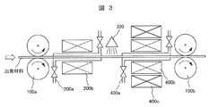
- FIG. 3 is a schematic view showing a configuration example of an apparatus for manufacturing the soft magnetic steel sheet of the present invention.
- a combination of roll mechanisms 100a and 100b enables the transfer of the starting material and the application of a stress field (compressive stress and / or tensile stress) to the starting material, and the atmosphere control mechanism.
- the combination of 200a and the heating mechanism 200b performs nitrogen-containing heat treatment while controlling the atmosphere, and the cooling mechanism 300 performs quenching on the starting material that has undergone the nitrogen-containing heat treatment.
- the atmosphere control mechanism 400a, the heating mechanism 400b, and the electromagnetic field application mechanism 400c In combination with, the tempering heat treatment can be performed while controlling the atmosphere and applying an electromagnetic field.
- Example 1 A commercially available low-carbon steel sheet (thickness 0.1 mm, C concentration 0.5 atomic%) was prepared as a starting material. Against the starting material, ammonia gas atmosphere (50% NH 3 -50% N 2 gas, 1 atm), after the first heat treatment for holding at 750 ° C. 10 hours, flushed with 100% N 2 gas The first nitrogen-containing heat treatment was performed to cool the mixture to 200 ° C. Then, a tempering heat treatment was carried out at 200 ° C. for 1 hour to prepare a soft magnetic steel sheet of Example 1. A resistance heating furnace was used as a heating device for performing nitrogen-forming heat treatment and tempering heat treatment.
- Test pieces for various property investigations were collected from the obtained soft magnetic steel plate of Example 1, and the C concentration, N concentration, detection phase identification, ⁇ 'phase and ⁇ 'phase and ⁇ phase volume fraction, ⁇ '" The phase "c / a" and magnetic properties were investigated.
- the concentration profile (unit: atomic%) from the sample surface to a depth of 50 ⁇ m was measured by the glow discharge emission analysis method (GD-OES), and the component concentration was determined from the average value.
- GD-OES glow discharge emission analysis method
- the C concentration was 0.5 atomic% and the N concentration was 2 atomic%. From this, the ratio of N concentration to C concentration "N concentration / C concentration" is 4.
- the volume fractions of the ⁇ 'phase, ⁇ 'phase, and ⁇ phase are detected by profile fitting after performing wide-angle X-ray diffraction measurement (WAXD) using Mo-K ⁇ and Cu-K ⁇ rays on the sample surface. And the integrated intensity of each diffraction peak was calculated. Next, the integrated intensity correction using the sensitivity coefficient described in the standard data was performed, and the volume fraction of the ⁇ 'phase, ⁇ 'phase, and ⁇ phase was calculated from the ratio of the integrated intensity. I asked. Further, from the diffraction peak of the ⁇ "phase, the ratio of the c-axis length to the a-axis length of the lattice constant of the ⁇ " phase "c / a" was calculated.
- WAXD wide-angle X-ray diffraction measurement
- Example 1 As a result of WAXD measurement, in Example 1, diffraction peaks of ⁇ phase, ⁇ 'phase, ⁇ 'phase and ⁇ phase were detected, ⁇ 'phase was 30% by volume, ⁇ 'phase was 20% by volume, and so on. The ⁇ phase was 0.5% by volume, and the “c / a” of the ⁇ ”phase was 1.04.
- the magnetic characteristics are measured by measuring the magnetization (unit: emu) of the sample at a magnetic field of 1.6 MA / m and a temperature of 20 ° C using a vibrating sample magnetometer (VSM, Riken Denshi Co., Ltd. BHV-525H), and measuring the sample volume and sample mass.
- the saturation magnetic flux density Bs (unit: T) and the coercive force Hc (unit: A / m) were obtained from the above.
- Bs of a low carbon steel sheet (C concentration 0.5 atomic%) as a starting material was also obtained.
- the soft magnetic steel sheet of Example 1 had a Bs of 2.22 T and an Hc of 70 A / m.
- the low carbon steel sheet of Standard Example 1 had a Bs of 2.12 T.
- Example 1 The specifications and measurement results of Example 1 and Reference Example 1 are summarized in Table 1 described later.
- Example 2 The same low-carbon steel sheet as in Example 1 (thickness 0.1 mm, C concentration 0.5 atomic%) was prepared. The same as in Example 1 except that the starting material is subjected to the same first nitrogen-containing heat treatment as in Example 1 and then a magnetic field (10 kOe) is applied in the width direction of the plate to be heat-treated during the tempering heat treatment. Then, a tempering heat treatment was performed in which 100% N 2 gas was flowed, cooled to 200 ° C., and held at 200 ° C. for 1 hour to prepare a soft magnetic steel plate of Example 2.
- Test pieces for various property investigations were collected from the obtained soft magnetic steel plate of Example 2, and the C concentration, N concentration, detection phase were identified, ⁇ 'phase, ⁇ 'phase and ⁇ were obtained in the same manner as in Example 1.
- the volume fraction of the phase, the "c / a" of the ⁇ "phase, and the magnetic properties were investigated.
- Example 2 As a result of GD-OES measurement, as in Example 1, the C concentration was 0.5 atomic%, the N concentration was 2 atomic%, and the "N concentration / C concentration" was 4. As a result of WAXD measurement, diffraction peaks of ⁇ phase, ⁇ 'phase, ⁇ 'phase and ⁇ phase are detected, ⁇ 'phase is 20% by volume, ⁇ 'phase is 20% by volume, and ⁇ phase is 0.4 volume. %, And the “c / a” of the ⁇ ”phase was 1.04. As a result of VSM measurement, the soft magnetic steel sheet of Example 2 had a Bs of 2.26 T and an Hc of 70 A / m. It was confirmed that by applying a magnetic field to the plate to be heat-treated during the tempering heat treatment, the effect of increasing Bs was confirmed.
- Example 2 The specifications of Example 2 and the measurement results are also shown in Table 1 described later.
- Example 3 The same low-carbon steel sheet as in Example 1 (thickness 0.1 mm, C concentration 0.5 atomic%) was prepared. The starting material is subjected to the same first nitrogen-containing heat treatment as in Example 1, and then a tensile stress (196 MPa) is applied in the longitudinal direction of the plate to be heat-treated during the tempering heat treatment. In the same manner, a tempering heat treatment was performed in which 100% N 2 gas was flowed, cooled to 200 ° C., and held at 200 ° C. for 1 hour to prepare a soft magnetic steel plate of Example 3.
- Test pieces for various property investigations were collected from the obtained soft magnetic steel plate of Example 3, and the C concentration, N concentration, detection phase were identified, ⁇ 'phase, ⁇ 'phase and ⁇ were obtained in the same manner as in Example 1.
- the volume fraction of the phase, the "c / a" of the ⁇ "phase, and the magnetic properties were investigated.
- Example 3 As a result of GD-OES measurement, as in Example 1, the C concentration was 0.5 atomic%, the N concentration was 2 atomic%, and the "N concentration / C concentration" was 4. As a result of WAXD measurement, diffraction peaks of ⁇ phase, ⁇ 'phase, ⁇ 'phase and ⁇ phase are detected, ⁇ 'phase is 35% by volume, ⁇ 'phase is 25% by volume, and ⁇ phase is 0.2 volume. %, And the “c / a” of the ⁇ ”phase was 1.06. As a result of VSM measurement, the soft magnetic steel sheet of Example 3 had a Bs of 2.32 T and an Hc of 60 A / m. It was confirmed that by applying stress to the plate to be heat-treated during the tempering heat treatment, the effect of increasing Bs was confirmed.
- Example 3 The specifications of Example 3 and the measurement results are also shown in Table 1 described later.
- Example 4 The same low-carbon steel sheet as in Example 1 (thickness 0.1 mm, C concentration 0.5 atomic%) was prepared. After the first nitrogen-containing heat treatment similar to that of Example 1 is performed on the starting material, a tensile stress (196 MPa) is applied in the longitudinal direction of the plate to be heat-treated and a magnetic field (10) is applied in the width direction during the tempering heat treatment. Except for applying kOe), tempering heat treatment was performed in the same manner as in Example 1 by flowing 100% N 2 gas, cooling to 200 ° C, and holding at 200 ° C for 24 hours to prepare the soft magnetic steel plate of Example 4. did.
- a tensile stress 196 MPa
- a magnetic field 10
- tempering heat treatment was performed in the same manner as in Example 1 by flowing 100% N 2 gas, cooling to 200 ° C, and holding at 200 ° C for 24 hours to prepare the soft magnetic steel plate of Example 4. did.
- Test pieces for various property investigations were collected from the obtained soft magnetic steel plate of Example 4, and the C concentration, N concentration, detection phase were identified, ⁇ 'phase, ⁇ 'phase and ⁇ were obtained in the same manner as in Example 1.
- the volume fraction of the phase, the "c / a" of the ⁇ "phase, and the magnetic properties were investigated.
- Example 2 As a result of GD-OES measurement, as in Example 1, the C concentration was 0.5 atomic%, the N concentration was 2 atomic%, and the "N concentration / C concentration" was 4. As a result of WAXD measurement, diffraction peaks of ⁇ phase, ⁇ 'phase, ⁇ 'phase and ⁇ phase are detected, ⁇ 'phase is 30% by volume, ⁇ 'phase is 15% by volume, and ⁇ phase volume ratio is It was 0.5% by volume, and the “c / a” of the ⁇ ”phase was 1.06. As a result of VSM measurement, the soft magnetic steel sheet of Example 4 had a Bs of 2.39 T and an Hc of 70 A / m. It was confirmed that Bs was further increased by combining stress application and magnetic field application to the plate to be heat-treated during the tempering heat treatment.
- Example 4 The specifications of Example 4 and the measurement results are also shown in Table 1 described later.
- Example 5 The same low-carbon steel sheet as in Example 1 (thickness 0.1 mm, C concentration 0.5 atomic%) was prepared.
- the starting material was subjected to the same first heat treatment as in Example 1, and then a second nitrogen-containing heat treatment for quenching by water cooling.
- the hardened material is subjected to a sub-zero treatment using liquid nitrogen (in this case, also referred to as a super-sub-zero treatment), and then a tempering heat treatment is carried out at 150 ° C. for 1 hour to obtain the soft magnetism of Example 5.
- a steel plate was produced.
- Test pieces for various property investigations were collected from the obtained soft magnetic steel plate of Example 5, and the C concentration, N concentration, detection phase were identified, ⁇ 'phase, ⁇ 'phase and ⁇ were obtained in the same manner as in Example 1.
- the volume fraction of the phase, the "c / a" of the ⁇ "phase, and the magnetic properties were investigated.
- Example 2 As a result of GD-OES measurement, as in Example 1, the C concentration was 0.5 atomic%, the N concentration was 2 atomic%, and the "N concentration / C concentration" was 4. As a result of WAXD measurement, diffraction peaks of ⁇ phase, ⁇ 'phase, ⁇ 'phase and ⁇ phase are detected, ⁇ 'phase is 20% by volume, ⁇ 'phase is 25% by volume, and ⁇ phase volume ratio is It was 0.3% by volume, and the “c / a” of the ⁇ ”phase was 1.07. As a result of VSM measurement, the soft magnetic steel sheet of Example 5 had a Bs of 2.28 T and an Hc of 80 A / m. By combining quenching and subzero treatment, it was confirmed that the ⁇ -phase volume fraction decreased and Bs increased as compared with the soft magnetic steel sheet of Example 1.
- Example 5 The specifications of Example 5 and the measurement results are also shown in Table 1 described later.
- Example 6 A commercially available low-carbon steel sheet (thickness 0.1 mm, C concentration 1 atomic%) different from that of Example 1 was prepared. Against the starting material, ammonia gas atmosphere (50% NH 3 -50% N 2 gas, 1 atm), after the first heat treatment for 1 hour at 750 ° C., the quenching by the N 2 gas cooling A second nitrogen-quenching heat treatment was performed. Next, a tempering heat treatment of holding the hardened material at 200 ° C. for 10 hours while applying a tensile stress (98 MPa) in the longitudinal direction was performed to prepare a soft magnetic steel sheet of Example 6.
- ammonia gas atmosphere 50% NH 3 -50% N 2 gas, 1 atm
- a second nitrogen-quenching heat treatment was performed.
- a tempering heat treatment of holding the hardened material at 200 ° C. for 10 hours while applying a tensile stress (98 MPa) in the longitudinal direction was performed to prepare a soft magnetic steel sheet of Example 6.
- Test pieces for various property investigations were collected from the obtained soft magnetic steel plate of Example 6, and the C concentration, N concentration, detection phase identification, ⁇ 'phase, ⁇ 'phase and ⁇ were performed in the same manner as in Example 1.
- the volume fraction of the phase, the "c / a" of the ⁇ "phase, and the magnetic properties were investigated.
- Bs of a low carbon steel sheet (C concentration 1 atomic%) as a starting material was also obtained.
- Example 2 As a result of GD-OES measurement, as in Example 1, the C concentration was 1 atomic%, the N concentration was 5 atomic%, and the "N concentration / C concentration" was 5. As a result of WAXD measurement, diffraction peaks of ⁇ phase, ⁇ 'phase, ⁇ 'phase and ⁇ phase are detected, ⁇ 'phase is 15% by volume, ⁇ 'phase is 20% by volume, and ⁇ phase volume ratio is It was 1% by volume, and the “c / a” of the ⁇ ”phase was 1.05. As a result of VSM measurement, the soft magnetic steel sheet of Example 6 had a Bs of 2.30 T. The low carbon steel sheet of Standard Example 2 had a Bs of 2.09 T.
- Example 6 The specifications of Example 6 and Reference Example 2 and the measurement results are also shown in Table 1 described later.
- Example 7 The same low-carbon steel sheet as in Example 6 (thickness 0.1 mm, C concentration 1 atomic%) was prepared. Against the starting material, ammonia gas atmosphere (50% NH 3 -50% N 2 gas, 1 atm), after the first ⁇ containing heat treatment of holding for 0.5 hours at 750 ° C., by N 2 gas cooling A second nitrogen-entering heat treatment for quenching was performed. Next, a tempering heat treatment of holding the hardened material at 200 ° C. for 1 hour while applying a tensile stress (98 MPa) in the longitudinal direction was performed to prepare a soft magnetic steel sheet of Example 7. In Example 7, a high-frequency induction heating furnace was used as a heating device for performing nitrogen-containing heat treatment and tempering heat treatment.
- Test pieces for various property investigations were collected from the obtained soft magnetic steel plate of Example 7, and the C concentration, N concentration, detection phase identification, ⁇ 'phase, ⁇ 'phase and ⁇ were performed in the same manner as in Example 1.
- the volume fraction of the phase, the "c / a" of the ⁇ "phase, and the magnetic properties were investigated.
- Example 6 As a result of GD-OES measurement, as in Example 6, the C concentration was 1 atomic%, the N concentration was 5 atomic%, and the "N concentration / C concentration" was 5. As a result of WAXD measurement, diffraction peaks of ⁇ phase, ⁇ 'phase, ⁇ 'phase and ⁇ phase are detected, ⁇ 'phase is 20% by volume, ⁇ 'phase is 25% by volume, and ⁇ phase volume ratio is It was 3% by volume, and the “c / a” of the ⁇ ”phase was 1.05. As a result of VSM measurement, the soft magnetic steel sheet of Example 7 had a Bs of 2.30 T. It was confirmed that by using a high frequency induction heating furnace as the heating device, the same characteristics as in Example 6 can be obtained in a shorter time.
- Example 7 The specifications of Example 7 and the measurement results are also shown in Table 1 described later.
- Example 8 A commercially available pure electromagnetic iron plate (thickness 0.05 mm, C concentration 0.01 atomic%) different from that of Example 1 was prepared. Against the starting material, ammonia gas atmosphere (80% NH 3 -20% H 2 gas, 1 atm), after the second heat treatment holding at 580 ° C. 10 hours, the to quenching by water cooling The nitrogen-containing heat treatment of No. 3 was performed. Next, a tempering heat treatment was performed in which a tensile stress (98 MPa) was applied in the longitudinal direction of the hardened material and a magnetic field (10 kOe) was applied in the thickness direction to maintain the material at 150 ° C. for 10 hours. The soft magnetic steel plate of the above was produced. A resistance heating furnace was used as a heating device for performing nitrogen-forming heat treatment and tempering heat treatment.
- Test pieces for various property investigations were collected from the obtained soft magnetic steel plate of Example 8, and the C concentration, N concentration, detection phase identification, ⁇ 'phase, ⁇ 'phase and ⁇ were performed in the same manner as in Example 1.
- the volume fraction of the phase, the "c / a" of the ⁇ "phase, and the magnetic properties were investigated.
- Bs of an electromagnetic pure iron plate (C concentration 0.01 atomic%) as a starting material was also determined.
- the C concentration was 0.01 atomic%
- the N concentration was 0.5 atomic%
- the "N concentration / C concentration" was 50.
- WAXD measurement diffraction peaks of ⁇ phase, ⁇ 'phase and ⁇ 'phase were detected, but diffraction peak of ⁇ phase was not detected.
- ⁇ 'phase was 20% by volume and ⁇ 'phase was 25.
- the volume% was%
- the ⁇ phase volume ratio was 0% by volume
- the “c / a” of the ⁇ ”phase was 1.06.
- the soft magnetic steel sheet of Example 8 had a Bs of 2.30 T and an Hc of 80 A / m.
- the electromagnetic pure iron plate of Standard Example 3 had a Bs of 2.14 T.
- the manufacturing process of the soft magnetic steel sheet is a combination of a temperature region below the A 1 transformation point (592 ° C.) in the Fe-N phase diagram, a nitrogen-containing heat treatment that does not pass through the ⁇ phase by quenching, and a tempering heat treatment. It is considered that the ⁇ -phase volume fraction became 0% by volume.
- Example 8 The specifications of Example 8 and Reference Example 3 and the measurement results are also shown in Table 1 described later.
- Example 9 An electromagnetic pure iron plate (thickness 0.1 mm, C concentration 0.01 atomic%) having a thickness different from that of Example 8 was prepared. Against the starting material, ammonia gas atmosphere (80% NH 3 -20% H 2 gas, 0.5 atm), 10 hours at 580 ° C. while applying a tensile stress (98 MPa) to the longitudinal direction of the starting material After the second heat treatment for holding, a third nitrogen-containing heat treatment for quenching by water cooling was performed. Next, a tempering heat treatment was performed in which a magnetic field (10 kOe) was applied in the width direction of the hardened material and the material was held at 150 ° C. for 1 hour to prepare a soft magnetic steel sheet of Example 9.
- a magnetic field (10 kOe) was applied in the width direction of the hardened material and the material was held at 150 ° C. for 1 hour to prepare a soft magnetic steel sheet of Example 9.
- Test pieces for various property investigations were collected from the obtained soft magnetic steel plate of Example 9, and the C concentration, N concentration, detection phase identification, ⁇ 'phase, ⁇ 'phase and ⁇ were performed in the same manner as in Example 1.
- the volume fraction of the phase, the "c / a" of the ⁇ "phase, and the magnetic properties were investigated.
- the C concentration was 0.01 atomic%
- the N concentration was 1.5 atomic%
- the "N concentration / C concentration" was 150.
- WAXD measurement diffraction peaks of ⁇ phase, ⁇ 'phase and ⁇ 'phase were detected, but diffraction peak of ⁇ phase was not detected.
- ⁇ 'phase was 25% by volume and ⁇ 'phase was 30. It was% by volume, the ⁇ phase volume ratio was 0% by volume, and the “c / a” of the ⁇ ”phase was 1.05.
- the soft magnetic steel sheet of Example 9 had a Bs of 2.30 T and an Hc of 50 A / m.
- Table 1 shows the specifications of Example 9 and the measurement results.
Landscapes
- Chemical & Material Sciences (AREA)
- Engineering & Computer Science (AREA)
- Metallurgy (AREA)
- Organic Chemistry (AREA)
- Mechanical Engineering (AREA)
- Materials Engineering (AREA)
- Physics & Mathematics (AREA)
- Crystallography & Structural Chemistry (AREA)
- Thermal Sciences (AREA)
- Power Engineering (AREA)
- Dispersion Chemistry (AREA)
- Chemical Kinetics & Catalysis (AREA)
- Electromagnetism (AREA)
- Manufacturing & Machinery (AREA)
- Soft Magnetic Materials (AREA)
- Solid-Phase Diffusion Into Metallic Material Surfaces (AREA)
- Iron Core Of Rotating Electric Machines (AREA)
Priority Applications (3)
| Application Number | Priority Date | Filing Date | Title |
|---|---|---|---|
| EP20908103.3A EP4083239A4 (en) | 2019-12-25 | 2020-08-28 | SOFT MAGNETIC STEEL SHEET, METHOD FOR THE PRODUCTION THEREOF AND CORE AND DYNAMOELECTRIC MACHINE IN WHICH THE SOFT MAGNETIC STEEL SHEET IS USED |
| US17/779,158 US12431269B2 (en) | 2019-12-25 | 2020-08-28 | Soft magnetic steel sheet, method for manufacturing the soft magnetic steel sheet, and core and dynamo-electric machine in which the soft magnetic steel sheet is used |
| CN202080088576.1A CN114829648A (zh) | 2019-12-25 | 2020-08-28 | 软磁性钢板、该软磁性钢板的制造方法、使用了该软磁性钢板的铁芯和旋转电机 |
Applications Claiming Priority (2)
| Application Number | Priority Date | Filing Date | Title |
|---|---|---|---|
| JP2019-234302 | 2019-12-25 | ||
| JP2019234302A JP7489773B2 (ja) | 2019-12-25 | 2019-12-25 | 軟磁性鋼板の製造方法 |
Publications (1)
| Publication Number | Publication Date |
|---|---|
| WO2021131162A1 true WO2021131162A1 (ja) | 2021-07-01 |
Family
ID=76575850
Family Applications (1)
| Application Number | Title | Priority Date | Filing Date |
|---|---|---|---|
| PCT/JP2020/032669 Ceased WO2021131162A1 (ja) | 2019-12-25 | 2020-08-28 | 軟磁性鋼板、該軟磁性鋼板の製造方法、該軟磁性鋼板を用いた鉄心および回転電機 |
Country Status (5)
| Country | Link |
|---|---|
| US (1) | US12431269B2 (enExample) |
| EP (1) | EP4083239A4 (enExample) |
| JP (1) | JP7489773B2 (enExample) |
| CN (1) | CN114829648A (enExample) |
| WO (1) | WO2021131162A1 (enExample) |
Cited By (5)
| Publication number | Priority date | Publication date | Assignee | Title |
|---|---|---|---|---|
| WO2022070508A1 (ja) * | 2020-09-30 | 2022-04-07 | 株式会社日立製作所 | 軟磁性材料、軟磁性材料の製造方法および電動機 |
| WO2023132141A1 (ja) * | 2022-01-06 | 2023-07-13 | 株式会社日立製作所 | 軟磁性鉄合金板、該軟磁性鉄合金板を用いた鉄心および回転電機 |
| WO2023186859A1 (en) * | 2022-03-30 | 2023-10-05 | Yasa Limited | Rotor for an axial flux machine |
| WO2023195226A1 (ja) * | 2022-04-06 | 2023-10-12 | 株式会社日立製作所 | 軟磁性鉄合金板、該軟磁性鉄合金板の製造方法、該軟磁性鉄合金板を用いた鉄心および回転電機 |
| GB2625466A (en) * | 2022-03-30 | 2024-06-19 | Yasa Ltd | A method of joining metal laminate to a rotor body |
Families Citing this family (2)
| Publication number | Priority date | Publication date | Assignee | Title |
|---|---|---|---|---|
| JP7365773B2 (ja) * | 2019-02-13 | 2023-10-20 | 株式会社日立製作所 | 軟磁性材料及びその製造方法並びに軟磁性材料を用いた電動機 |
| JP2024121923A (ja) * | 2023-02-28 | 2024-09-09 | パーカー熱処理工業株式会社 | 連続式熱処理装置 |
Citations (8)
| Publication number | Priority date | Publication date | Assignee | Title |
|---|---|---|---|---|
| JPS61143557A (ja) * | 1984-12-18 | 1986-07-01 | Kawasaki Steel Corp | 飽和磁気モ−メントが高い磁性材料 |
| JPS637332A (ja) * | 1986-06-27 | 1988-01-13 | Kawasaki Steel Corp | 高い飽和磁化を有する薄帯の製造方法 |
| JPH03244108A (ja) * | 1990-02-22 | 1991-10-30 | Nippon Steel Corp | 高飽和磁束密度を有するバルクα〃窒化鉄の製造方法 |
| JPH04268027A (ja) * | 1991-02-21 | 1992-09-24 | Kawasaki Steel Corp | 高い飽和磁化を有する磁性薄帯の製造方法 |
| JPH07118703A (ja) * | 1993-10-21 | 1995-05-09 | Mitsubishi Materials Corp | 高い飽和磁束密度を有するFe−N系軟磁性粉末の製造方法 |
| JP2001176715A (ja) | 1999-12-21 | 2001-06-29 | Toyota Central Res & Dev Lab Inc | 高飽和磁化Fe−N系磁性体 |
| JP2005226116A (ja) * | 2004-02-12 | 2005-08-25 | Toyota Motor Corp | 高硬度高磁気特性鋼材及びその製造方法 |
| US20150380158A1 (en) * | 2014-06-30 | 2015-12-31 | Regents Of The University Of Minnesota | Applied magnetic field synthesis and processing of iron nitride magnetic materials |
Family Cites Families (4)
| Publication number | Priority date | Publication date | Assignee | Title |
|---|---|---|---|---|
| JP3021957B2 (ja) * | 1992-05-14 | 2000-03-15 | 川崎製鉄株式会社 | 高い飽和磁化を有するFe16N2鉄窒化物の製造方法 |
| JP6051456B2 (ja) | 2011-12-15 | 2016-12-27 | ケース ウェスターン リザーヴ ユニヴァーシティ | 転移により得られる希土類元素を含まない窒化物磁石及びその製造方法 |
| JP2024143557A (ja) | 2023-03-30 | 2024-10-11 | ノリタケ株式会社 | インクジェットインク |
| JP2025007332A (ja) | 2023-06-30 | 2025-01-17 | 京セラ株式会社 | 配線基板、パッケージおよび圧電デバイス |
-
2019
- 2019-12-25 JP JP2019234302A patent/JP7489773B2/ja active Active
-
2020
- 2020-08-28 EP EP20908103.3A patent/EP4083239A4/en active Pending
- 2020-08-28 CN CN202080088576.1A patent/CN114829648A/zh active Pending
- 2020-08-28 US US17/779,158 patent/US12431269B2/en active Active
- 2020-08-28 WO PCT/JP2020/032669 patent/WO2021131162A1/ja not_active Ceased
Patent Citations (8)
| Publication number | Priority date | Publication date | Assignee | Title |
|---|---|---|---|---|
| JPS61143557A (ja) * | 1984-12-18 | 1986-07-01 | Kawasaki Steel Corp | 飽和磁気モ−メントが高い磁性材料 |
| JPS637332A (ja) * | 1986-06-27 | 1988-01-13 | Kawasaki Steel Corp | 高い飽和磁化を有する薄帯の製造方法 |
| JPH03244108A (ja) * | 1990-02-22 | 1991-10-30 | Nippon Steel Corp | 高飽和磁束密度を有するバルクα〃窒化鉄の製造方法 |
| JPH04268027A (ja) * | 1991-02-21 | 1992-09-24 | Kawasaki Steel Corp | 高い飽和磁化を有する磁性薄帯の製造方法 |
| JPH07118703A (ja) * | 1993-10-21 | 1995-05-09 | Mitsubishi Materials Corp | 高い飽和磁束密度を有するFe−N系軟磁性粉末の製造方法 |
| JP2001176715A (ja) | 1999-12-21 | 2001-06-29 | Toyota Central Res & Dev Lab Inc | 高飽和磁化Fe−N系磁性体 |
| JP2005226116A (ja) * | 2004-02-12 | 2005-08-25 | Toyota Motor Corp | 高硬度高磁気特性鋼材及びその製造方法 |
| US20150380158A1 (en) * | 2014-06-30 | 2015-12-31 | Regents Of The University Of Minnesota | Applied magnetic field synthesis and processing of iron nitride magnetic materials |
Non-Patent Citations (1)
| Title |
|---|
| See also references of EP4083239A4 |
Cited By (10)
| Publication number | Priority date | Publication date | Assignee | Title |
|---|---|---|---|---|
| WO2022070508A1 (ja) * | 2020-09-30 | 2022-04-07 | 株式会社日立製作所 | 軟磁性材料、軟磁性材料の製造方法および電動機 |
| JP2022056923A (ja) * | 2020-09-30 | 2022-04-11 | 株式会社日立製作所 | 軟磁性材料、軟磁性材料の製造方法および電動機 |
| JP7545281B2 (ja) | 2020-09-30 | 2024-09-04 | 株式会社日立製作所 | 軟磁性材料、軟磁性材料の製造方法および電動機 |
| WO2023132141A1 (ja) * | 2022-01-06 | 2023-07-13 | 株式会社日立製作所 | 軟磁性鉄合金板、該軟磁性鉄合金板を用いた鉄心および回転電機 |
| JP2023100325A (ja) * | 2022-01-06 | 2023-07-19 | 株式会社日立製作所 | 軟磁性鉄合金板、該軟磁性鉄合金板を用いた鉄心および回転電機 |
| JP7768773B2 (ja) | 2022-01-06 | 2025-11-12 | 株式会社日立製作所 | 軟磁性鉄合金板、該軟磁性鉄合金板を用いた鉄心および回転電機 |
| WO2023186859A1 (en) * | 2022-03-30 | 2023-10-05 | Yasa Limited | Rotor for an axial flux machine |
| GB2625466A (en) * | 2022-03-30 | 2024-06-19 | Yasa Ltd | A method of joining metal laminate to a rotor body |
| GB2625466B (en) * | 2022-03-30 | 2024-10-23 | Yasa Ltd | A method of joining metal laminate to a rotor body |
| WO2023195226A1 (ja) * | 2022-04-06 | 2023-10-12 | 株式会社日立製作所 | 軟磁性鉄合金板、該軟磁性鉄合金板の製造方法、該軟磁性鉄合金板を用いた鉄心および回転電機 |
Also Published As
| Publication number | Publication date |
|---|---|
| CN114829648A (zh) | 2022-07-29 |
| JP7489773B2 (ja) | 2024-05-24 |
| JP2021102799A (ja) | 2021-07-15 |
| EP4083239A1 (en) | 2022-11-02 |
| US20220328225A1 (en) | 2022-10-13 |
| US12431269B2 (en) | 2025-09-30 |
| EP4083239A4 (en) | 2024-01-17 |
Similar Documents
| Publication | Publication Date | Title |
|---|---|---|
| JP7489773B2 (ja) | 軟磁性鋼板の製造方法 | |
| JP5130270B2 (ja) | 磁性材料及びそれを用いたモータ | |
| JP2013067863A (ja) | 軟磁性合金粉末およびこれを用いた磁性部品 | |
| JP7365773B2 (ja) | 軟磁性材料及びその製造方法並びに軟磁性材料を用いた電動機 | |
| JP2012246174A (ja) | 窒化鉄材の製造方法及び窒化鉄材 | |
| CN117255870B (zh) | 软磁性铁合金板、该软磁性铁合金板的制造方法、使用该软磁性铁合金板的铁芯及旋转电机 | |
| JP7629764B2 (ja) | 軟磁性鉄合金板およびその製造方法 | |
| CN116134160B (zh) | 软磁性铁板、该软磁性铁板的制造方法、使用了该软磁性铁板的铁芯和旋转电机 | |
| US12512239B2 (en) | Soft magnetic iron sheet, method for producing soft magnetic iron sheet, and, iron core and dynamo-electric machine, each using soft magnetic iron sheet | |
| JP7669180B2 (ja) | 磁性体材料、鉄心および回転電機 | |
| JP2004265907A (ja) | 硬質磁性組成物 | |
| US20250055329A1 (en) | Laminated Iron Core and Rotating Electric Machine Using the Same | |
| JP7768773B2 (ja) | 軟磁性鉄合金板、該軟磁性鉄合金板を用いた鉄心および回転電機 | |
| JP2014207342A (ja) | 磁石用材料、磁石用材料の製造方法、及び磁石 | |
| JP2023154178A (ja) | 軟磁性鉄合金板、該軟磁性鉄合金板の製造方法、該軟磁性鉄合金板を用いた鉄心および回転電機 | |
| JP2025101371A (ja) | 軟磁性鉄合金板、該鉄合金板の製造方法、該鉄合金板を用いた鉄心および回転電機 | |
| WO2024202156A1 (ja) | 軟磁性合金板、該軟磁性合金板の製造方法、該軟磁性合金板を用いた鉄心および回転電機 | |
| JPH04254303A (ja) | 永久磁石 | |
| JP2005264279A (ja) | 硬質磁性組成物 | |
| JP2005050970A (ja) | 硬質磁性組成物及びその製造方法 | |
| JP2005171302A (ja) | 硬質磁性組成物 |
Legal Events
| Date | Code | Title | Description |
|---|---|---|---|
| 121 | Ep: the epo has been informed by wipo that ep was designated in this application |
Ref document number: 20908103 Country of ref document: EP Kind code of ref document: A1 |
|
| NENP | Non-entry into the national phase |
Ref country code: DE |
|
| ENP | Entry into the national phase |
Ref document number: 2020908103 Country of ref document: EP Effective date: 20220725 |
|
| WWG | Wipo information: grant in national office |
Ref document number: 17779158 Country of ref document: US |