WO2021117164A1 - 二酸化炭素の気相還元装置、および、二酸化炭素の気相還元方法 - Google Patents
二酸化炭素の気相還元装置、および、二酸化炭素の気相還元方法 Download PDFInfo
- Publication number
- WO2021117164A1 WO2021117164A1 PCT/JP2019/048510 JP2019048510W WO2021117164A1 WO 2021117164 A1 WO2021117164 A1 WO 2021117164A1 JP 2019048510 W JP2019048510 W JP 2019048510W WO 2021117164 A1 WO2021117164 A1 WO 2021117164A1
- Authority
- WO
- WIPO (PCT)
- Prior art keywords
- reduction
- tank
- electrode
- carbon dioxide
- oxidation
- Prior art date
- Legal status (The legal status is an assumption and is not a legal conclusion. Google has not performed a legal analysis and makes no representation as to the accuracy of the status listed.)
- Ceased
Links
Images




Classifications
-
- C—CHEMISTRY; METALLURGY
- C25—ELECTROLYTIC OR ELECTROPHORETIC PROCESSES; APPARATUS THEREFOR
- C25B—ELECTROLYTIC OR ELECTROPHORETIC PROCESSES FOR THE PRODUCTION OF COMPOUNDS OR NON-METALS; APPARATUS THEREFOR
- C25B9/00—Cells or assemblies of cells; Constructional parts of cells; Assemblies of constructional parts, e.g. electrode-diaphragm assemblies; Process-related cell features
- C25B9/17—Cells comprising dimensionally-stable non-movable electrodes; Assemblies of constructional parts thereof
- C25B9/19—Cells comprising dimensionally-stable non-movable electrodes; Assemblies of constructional parts thereof with diaphragms
- C25B9/23—Cells comprising dimensionally-stable non-movable electrodes; Assemblies of constructional parts thereof with diaphragms comprising ion-exchange membranes in or on which electrode material is embedded
-
- C—CHEMISTRY; METALLURGY
- C25—ELECTROLYTIC OR ELECTROPHORETIC PROCESSES; APPARATUS THEREFOR
- C25B—ELECTROLYTIC OR ELECTROPHORETIC PROCESSES FOR THE PRODUCTION OF COMPOUNDS OR NON-METALS; APPARATUS THEREFOR
- C25B1/00—Electrolytic production of inorganic compounds or non-metals
- C25B1/01—Products
- C25B1/23—Carbon monoxide or syngas
-
- C—CHEMISTRY; METALLURGY
- C25—ELECTROLYTIC OR ELECTROPHORETIC PROCESSES; APPARATUS THEREFOR
- C25B—ELECTROLYTIC OR ELECTROPHORETIC PROCESSES FOR THE PRODUCTION OF COMPOUNDS OR NON-METALS; APPARATUS THEREFOR
- C25B1/00—Electrolytic production of inorganic compounds or non-metals
- C25B1/50—Processes
- C25B1/55—Photoelectrolysis
-
- C—CHEMISTRY; METALLURGY
- C25—ELECTROLYTIC OR ELECTROPHORETIC PROCESSES; APPARATUS THEREFOR
- C25B—ELECTROLYTIC OR ELECTROPHORETIC PROCESSES FOR THE PRODUCTION OF COMPOUNDS OR NON-METALS; APPARATUS THEREFOR
- C25B15/00—Operating or servicing cells
-
- C—CHEMISTRY; METALLURGY
- C25—ELECTROLYTIC OR ELECTROPHORETIC PROCESSES; APPARATUS THEREFOR
- C25B—ELECTROLYTIC OR ELECTROPHORETIC PROCESSES FOR THE PRODUCTION OF COMPOUNDS OR NON-METALS; APPARATUS THEREFOR
- C25B15/00—Operating or servicing cells
- C25B15/08—Supplying or removing reactants or electrolytes; Regeneration of electrolytes
-
- C—CHEMISTRY; METALLURGY
- C25—ELECTROLYTIC OR ELECTROPHORETIC PROCESSES; APPARATUS THEREFOR
- C25B—ELECTROLYTIC OR ELECTROPHORETIC PROCESSES FOR THE PRODUCTION OF COMPOUNDS OR NON-METALS; APPARATUS THEREFOR
- C25B3/00—Electrolytic production of organic compounds
- C25B3/01—Products
- C25B3/03—Acyclic or carbocyclic hydrocarbons
-
- C—CHEMISTRY; METALLURGY
- C25—ELECTROLYTIC OR ELECTROPHORETIC PROCESSES; APPARATUS THEREFOR
- C25B—ELECTROLYTIC OR ELECTROPHORETIC PROCESSES FOR THE PRODUCTION OF COMPOUNDS OR NON-METALS; APPARATUS THEREFOR
- C25B3/00—Electrolytic production of organic compounds
- C25B3/01—Products
- C25B3/07—Oxygen containing compounds
-
- C—CHEMISTRY; METALLURGY
- C25—ELECTROLYTIC OR ELECTROPHORETIC PROCESSES; APPARATUS THEREFOR
- C25B—ELECTROLYTIC OR ELECTROPHORETIC PROCESSES FOR THE PRODUCTION OF COMPOUNDS OR NON-METALS; APPARATUS THEREFOR
- C25B3/00—Electrolytic production of organic compounds
- C25B3/20—Processes
- C25B3/25—Reduction
- C25B3/26—Reduction of carbon dioxide
-
- C—CHEMISTRY; METALLURGY
- C25—ELECTROLYTIC OR ELECTROPHORETIC PROCESSES; APPARATUS THEREFOR
- C25B—ELECTROLYTIC OR ELECTROPHORETIC PROCESSES FOR THE PRODUCTION OF COMPOUNDS OR NON-METALS; APPARATUS THEREFOR
- C25B9/00—Cells or assemblies of cells; Constructional parts of cells; Assemblies of constructional parts, e.g. electrode-diaphragm assemblies; Process-related cell features
- C25B9/17—Cells comprising dimensionally-stable non-movable electrodes; Assemblies of constructional parts thereof
- C25B9/19—Cells comprising dimensionally-stable non-movable electrodes; Assemblies of constructional parts thereof with diaphragms
- C25B9/21—Cells comprising dimensionally-stable non-movable electrodes; Assemblies of constructional parts thereof with diaphragms two or more diaphragms
-
- C—CHEMISTRY; METALLURGY
- C25—ELECTROLYTIC OR ELECTROPHORETIC PROCESSES; APPARATUS THEREFOR
- C25B—ELECTROLYTIC OR ELECTROPHORETIC PROCESSES FOR THE PRODUCTION OF COMPOUNDS OR NON-METALS; APPARATUS THEREFOR
- C25B9/00—Cells or assemblies of cells; Constructional parts of cells; Assemblies of constructional parts, e.g. electrode-diaphragm assemblies; Process-related cell features
- C25B9/50—Cells or assemblies of cells comprising photoelectrodes; Assemblies of constructional parts thereof
-
- C—CHEMISTRY; METALLURGY
- C25—ELECTROLYTIC OR ELECTROPHORETIC PROCESSES; APPARATUS THEREFOR
- C25B—ELECTROLYTIC OR ELECTROPHORETIC PROCESSES FOR THE PRODUCTION OF COMPOUNDS OR NON-METALS; APPARATUS THEREFOR
- C25B1/00—Electrolytic production of inorganic compounds or non-metals
- C25B1/01—Products
- C25B1/02—Hydrogen or oxygen
- C25B1/04—Hydrogen or oxygen by electrolysis of water
-
- C—CHEMISTRY; METALLURGY
- C25—ELECTROLYTIC OR ELECTROPHORETIC PROCESSES; APPARATUS THEREFOR
- C25B—ELECTROLYTIC OR ELECTROPHORETIC PROCESSES FOR THE PRODUCTION OF COMPOUNDS OR NON-METALS; APPARATUS THEREFOR
- C25B11/00—Electrodes; Manufacture thereof not otherwise provided for
- C25B11/04—Electrodes; Manufacture thereof not otherwise provided for characterised by the material
- C25B11/042—Electrodes formed of a single material
- C25B11/049—Photocatalysts
Definitions
- the present invention relates to a carbon dioxide gas phase reducing device and a carbon dioxide gas phase reducing method.
- Non-Patent Document 1 an ion exchange membrane (Nafion (registered trademark)) and a reducing electrode (Cu) are combined between an oxidation tank on the left side and a reduction tank on the right side. It is constructed by arranging a gas reduction sheet. The ion exchange membrane is arranged toward the oxidation tank side, and the reduction electrode is arranged toward the reduction tank side.
- the oxide tank is filled with an aqueous solution of potassium hydroxide (KOH) as an electrolytic solution, and the oxide electrode of aluminum gallium nitride (AlGaN) in which a catalyst of nickel oxide (NiO) is laminated is immersed in the aqueous solution.
- KOH potassium hydroxide
- AlGaN aluminum gallium nitride
- NiO nickel oxide
- the oxide electrode is connected to the reduction electrode of the gas reduction sheet by a conducting wire.
- helium (He) is put into the potassium hydroxide aqueous solution in the oxidation tank and carbon dioxide (CO 2 ) is put into the reduction tank, and light (hv) is directed to the oxidation electrode.
- the carbon dioxide reduction reaction proceeds at the three-phase interface consisting of the ion exchange film (Nafion) of the gas reduction sheet, the reduction electrode (Cu), and the carbon dioxide (CO 2) in the reduction tank.
- oxygen is generated by the oxidation reaction of water.
- hydrogen is generated by the reduction reaction of protons in the ion exchange membrane, and carbon monoxide and formic acid are generated by the reduction reaction of carbon dioxide.
- the potassium hydroxide aqueous solution which is an electrolytic solution
- the reducing electrode deteriorates, the reaction field of the carbon dioxide reduction reaction is lost, and the carbon dioxide reduction reaction. Life will be reduced.
- the potassium hydroxide aqueous solution is injected into the oxide tank when the operation of the gas phase reducing device is started, and the water is discharged from the oxide tank when the operation is stopped, so that the contact between the potassium hydroxide aqueous solution and the reducing electrode is in the gas phase.
- a method of limiting only when the reduction device is operated is also conceivable. However, in the case of this method, oxygen generated in the oxide tank is released from the oxide tank when the valve is opened and closed, which makes recovery difficult.
- the present invention has been made in view of the above circumstances, and an object of the present invention is to provide a technique capable of suppressing deterioration of a reducing electrode and improving the life of a carbon dioxide reduction reaction on the reducing electrode. Is.
- the carbon dioxide gas phase reducing device is arranged between an oxide tank including an oxide electrode, a reduction tank to which carbon dioxide is supplied, and the oxide tank and the reduction tank, and is used to prepare an electrolytic solution. It is a gas reduction sheet in which an intermediate tank capable of injecting and discharging water, an ion exchange film arranged between the oxidation tank and the intermediate tank, and an ion exchange film and a reduction electrode are laminated. A gas reduction sheet arranged between the reduction tank and the intermediate tank, a lead wire connecting the oxidation electrode and the reduction electrode, and a lead wire for connecting the reduction electrode to the intermediate tank and the reduction electrode toward the reduction tank. To be equipped.
- the carbon dioxide gas-phase reduction method is the carbon dioxide gas-phase reduction method performed by the carbon dioxide gas-phase reduction device, wherein the carbon dioxide gas-phase reduction device includes an oxide tank including an oxidation electrode. , Arranged between the reducing tank to which carbon dioxide is supplied, the intermediate tank which is arranged between the oxidizing tank and the reducing tank and capable of injecting and discharging the electrolytic solution, and between the oxidizing tank and the intermediate tank. It is a gas reduction sheet in which the ion exchange film, the ion exchange film, and the reduction electrode are laminated, and the ion exchange film is directed toward the intermediate tank, the reduction electrode is directed at the reduction tank, and the reduction tank and the reduction tank are described.
- a gas reduction sheet arranged between the intermediate tank and a lead wire connecting the oxidation electrode and the reduction electrode are provided, and an electrolytic solution is injected into the oxidation tank and carbon dioxide is supplied to the reduction tank.
- the first step of injecting the electrolytic solution into the intermediate tank only when the oxidizing electrode is irradiated with light is performed.
- the carbon dioxide gas-phase reduction method is the carbon dioxide gas-phase reduction method performed by the carbon dioxide gas-phase reduction device, wherein the carbon dioxide gas-phase reduction device includes an oxide tank including an oxidation electrode. , Arranged between the reducing tank to which carbon dioxide is supplied, the intermediate tank which is arranged between the oxidizing tank and the reducing tank and capable of injecting and discharging the electrolytic solution, and between the oxidizing tank and the intermediate tank. It is a gas reduction sheet in which the ion exchange film, the ion exchange film, and the reduction electrode are laminated, and the ion exchange film is directed toward the intermediate tank, the reduction electrode is directed at the reduction tank, and the reduction tank and the reduction tank are described.
- a gas reduction sheet arranged between the intermediate tank and a lead wire connecting the oxidation electrode and the reduction electrode are provided, and an electrolytic solution is injected into the oxidation tank and carbon dioxide is supplied to the reduction tank.
- the first step of injecting the electrolytic solution into the intermediate tank only when a voltage is applied between the oxidizing electrode and the reducing electrode is performed.
- the present invention it is possible to provide a technique capable of suppressing deterioration of the reducing electrode and improving the life of the carbon dioxide reduction reaction on the reducing electrode.
- FIG. 1 is a configuration diagram showing a configuration of a carbon dioxide gas phase reducing device according to Examples 1 to 4.
- FIG. 2 is a diagram showing a method for producing a gas reduction sheet using an electroless plating method.
- FIG. 3 is a diagram showing a light irradiation time and a voltage application time used in Examples 1 and 5.
- FIG. 4 is a diagram showing a light irradiation time and a voltage application time used in Examples 2 and 6.
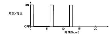
- FIG. 5 is a diagram showing a light irradiation time and a voltage application time used in Examples 3 and 7.
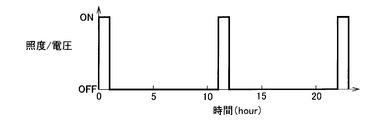
- FIG. 6 is a diagram showing a light irradiation time and a voltage application time used in Examples 4 and 8.
- FIG. 7 is a configuration diagram showing a configuration of a carbon dioxide gas phase reducing device according to Examples 5 to 8.
- FIG. 8 is a configuration diagram showing the configuration of a conventional carbon dioxide gas phase reducing device.
- the present invention relates to a carbon dioxide gas-phase reducing device that induces a carbon dioxide reduction reaction by light irradiation or causes an electrolytic reduction reaction of carbon dioxide to improve the life of the reduction reaction, and is an invention of a fuel generation technique or the like. It belongs to the technical field of solar energy conversion technology.
- the present invention uses a gas reduction sheet in which a reducing electrode is directly formed on an ion exchange membrane, and the gas phase of carbon dioxide that reduces carbon dioxide by directly supplying the carbon dioxide of the gas phase to the surface of the reducing electrode.
- a gas reduction sheet in which a reducing electrode is directly formed on an ion exchange membrane, and the gas phase of carbon dioxide that reduces carbon dioxide by directly supplying the carbon dioxide of the gas phase to the surface of the reducing electrode.
- an intermediate tank capable of injecting and discharging the electrolytic solution is arranged between the oxidation tank and the reduction tank. Further, only when the oxide electrode in the oxide tank is irradiated with light, or when a voltage is applied between the oxidation electrode and the reduction electrode, the electrolytic solution is injected into the intermediate tank to the reducing electrode. When they are brought into contact with each other, a carbon dioxide reduction reaction is caused at the reduction electrode of the gas reduction sheet.
- FIG. 1 is a configuration diagram showing a configuration of a carbon dioxide gas phase reducing device according to the first embodiment.
- the carbon dioxide gas phase reducing device is arranged between the oxide tank 2 including the oxidation electrode 1, the reduction tank 3 to which carbon dioxide (CO 2 ) is supplied, and the oxide tank 2 and the reduction tank 3, and is an electrolytic solution.
- It is a gas reduction sheet in which an intermediate tank 4 capable of injecting and discharging water, an ion exchange film 5 arranged between the oxidation tank 2 and the intermediate tank 4, an ion exchange film 6 and a reduction electrode 7 are laminated.
- the gas reduction sheet 100 arranged between the reduction tank 3 and the intermediate tank 4, the oxidation electrode 1 and the reduction electrode 7 with the ion exchange film 6 directed toward the intermediate tank 4 and the reducing electrode 7 directed toward the reducing tank 3.
- a lead wire 8 for connecting the two, and a light source 9 for irradiating the oxide electrode 1 with light are provided. The details will be described below.
- n-GaN n-type gallium nitride
- AlGaN aluminum gallium nitride
- the oxide electrode 1 is formed on the n-GaN. It is composed by forming a co-catalyst thin film of nickel oxide (NiO) by vacuum-depositing nickel (Ni) and performing heat treatment.
- NiO is a catalyst layer.
- AlGaN is a light absorption layer.
- the oxidation electrode 1 is installed so as to be immersed in the aqueous solution 10 which is the electrolytic solution injected into the oxidation tank 2.
- the aqueous solution 10 in the oxidation tank 2 is a 1 mol / L potassium hydroxide (KOH) aqueous solution.
- the oxidation tank 2 and the intermediate tank 4 are separated by an ion exchange membrane 5.
- the aqueous solution 11 as the electrolytic solution to be injected into the intermediate tank 4 is also a 1 mol / L potassium hydroxide aqueous solution.
- the intermediate tank 4 and the reduction tank 3 are separated by a gas reduction sheet 100 in which a reduction electrode 7 is directly formed on the ion exchange membrane 6.
- the ion exchange membrane 6 is arranged on the intermediate tank 4 side, and the reducing electrode 7 is arranged on the reducing tank 3 side.
- the ion exchange membrane 5 arranged between the oxidation tank 2 and the intermediate tank 4 and the ion exchange membrane 6 of the gas reduction sheet 100 arranged between the intermediate tank 4 and the reduction tank 3 are both Nafion. (Registered trademark) is used. Copper (Cu) is used for the reducing electrode 7.
- the oxidation electrode 1 immersed in the aqueous solution 10 in the oxidation tank 2 and the reduction electrode 7 of the gas reduction sheet 100 arranged toward the reduction tank 3 are connected by a conducting wire 8.
- a 300 W high-pressure xenon lamp is used as the light source 9.
- the light output from the light source 9 cuts wavelengths of 450 nm or more.
- FIG. 2 is a diagram showing a reaction system of an electroless plating method used as a method for producing a gas reduction sheet 100.
- One side of the ion exchange membrane 6 is polished. Further, in order to improve the proton mobility of the ion exchange membrane 6, the ion exchange membrane 6 is immersed in nitric acid and boiling pure water, respectively.
- the two tanks 21 and 22 on the left and right are filled with the plating solution 31 and the reducing agent 32 shown in Table 1, respectively.
- the tank 21 and the tank 22 are separated by an ion exchange membrane 6.
- the ion exchange membrane 6 is arranged with the polishing surface facing the plating solution 31 side. Since NaBH 4, which is the main component of the reducing agent 32, is a polar compound, it permeates the ion exchange membrane 6.
- Carbon dioxide gas phase reduction method Next, a carbon dioxide gas phase reduction method performed by the carbon dioxide gas phase reduction device will be described.
- the NiO-forming surface of the oxide electrode 1 is fixed toward the light source 9 so that the NiO-forming surface of the oxide electrode 1 serves as a light receiving surface (first step).
- the light receiving area of the oxide electrode 1 was 3.8 cm 2 .
- the tube 12 is put into the aqueous solution 10 in the oxidation tank 2 and helium (He) is poured into the aqueous solution 10 at a flow rate of 5 ml / min, and carbon dioxide (CO 2 ) is supplied to the reduction tank 3 from the gas input port 13. Pour in at the same flow rate (third step).
- He helium
- CO 2 carbon dioxide
- a 1 mol / L potassium hydroxide aqueous solution 11 is poured into the intermediate tank 4 from the aqueous solution input port 14, and the light source is used.
- the oxide electrode 1 is uniformly irradiated with light using No. 9 (fourth step).
- the carbon dioxide reduction reaction proceeds at the three-phase interface composed of the ion exchange membrane (Nafion) 6 in the gas reduction sheet 100, the reduction electrode (Cu) 7, and the carbon dioxide (CO 2) in the gas phase.
- the surface area of the reducing electrode 7 to which carbon dioxide is directly supplied is about 6.8 cm 2 .
- the aqueous solution 11 is discharged from the aqueous solution output port 15 of the intermediate tank 4 (fifth step).
- the "first step” described in the "claims” corresponds to the second step and the third step.
- the second step and the third step may be carried out at the same timing.
- the step of pouring carbon dioxide into the reduction tank 3 may be carried out at a timing prior to the step of injecting the aqueous solution 10 into the oxidation tank 2.
- the "second step” described in the "claims” corresponds to the fourth step and the fifth step.
- Example 1 the oxide electrode 1 was irradiated with light having a profile-set illuminance as shown in FIG.
- the net light irradiation time is repeated by repeating "Irradiating the oxide electrode 1 with light having an illuminance of 2.2 mW / cm 2 having a wavelength region of 365 nm or more for 1 hour and then waiting for 1 hour without irradiating the light". Allow the reaction to proceed until 3 hours are reached. Further, when the light irradiation is stopped, the aqueous solution 11 is discharged from the intermediate tank 4, and when the light irradiation is started again, the aqueous solution 11 is injected into the intermediate tank 4.
- Concentration analysis of gas products in each reaction vessel was performed using a gas chromatograph at any time during light irradiation.
- the liquid product in the reduction tank 3 was subjected to concentration analysis by a liquid chromatograph.
- oxygen was generated in the oxidation tank 2 by the oxidation reaction of water using the holes.
- hydrogen was produced by the reduction reaction of protons using electrons, and carbon monoxide, formic acid, formaldehyde, methane, ethylene, methanol, and ethanol were produced by the reduction reaction of carbon dioxide.
- Example 2 also uses the same carbon dioxide gas phase reducing device as in Example 1 shown in FIG.
- the oxide electrode 1 was irradiated with light having a profile-set illuminance as shown in FIG.
- the net light irradiation time is repeated by repeating "Irradiating the oxide electrode 1 with light having an illuminance of 2.2 mW / cm 2 having a wavelength region of 365 nm or more for 1 hour and then waiting for 3 hours without irradiating the light”. Allow the reaction to proceed until 3 hours are reached.
- Example 1 when the light irradiation is stopped, the aqueous solution 11 is discharged from the intermediate tank 4, and when the light irradiation is started again, the aqueous solution 11 is injected into the intermediate tank 4. In other respects, it is the same as in Example 1.
- Example 3 also uses the same carbon dioxide gas phase reducing device as in Example 1 shown in FIG.
- the oxide electrode 1 was irradiated with light having a profile-set illuminance as shown in FIG.
- the net light irradiation time is repeated by repeating "Irradiating the oxide electrode 1 with light having an illuminance of 2.2 mW / cm 2 having a wavelength region of 365 nm or more for 1 hour and then waiting for 5 hours without irradiating the light”. Allow the reaction to proceed until 3 hours are reached.
- Example 1 when the light irradiation is stopped, the aqueous solution 11 is discharged from the intermediate tank 4, and when the light irradiation is started again, the aqueous solution 11 is injected into the intermediate tank 4. In other respects, it is the same as in Example 1.
- Example 4 also uses the same carbon dioxide gas phase reducing device as in Example 1 shown in FIG.
- the oxide electrode 1 was irradiated with light having a profile-set illuminance as shown in FIG.
- the net light irradiation time is repeated by repeating "Irradiating the oxide electrode 1 with light having an illuminance of 2.2 mW / cm 2 having a wavelength region of 365 nm or more for 1 hour and then waiting for 10 hours without irradiating the light”. Allow the reaction to proceed until 3 hours are reached.
- Example 1 when the light irradiation is stopped, the aqueous solution 11 is discharged from the intermediate tank 4, and when the light irradiation is started again, the aqueous solution 11 is injected into the intermediate tank 4. In other respects, it is the same as in Example 1.
- FIG. 7 is a block diagram showing the configuration of the carbon dioxide gas phase reducing device according to the fifth embodiment.
- the power supply 16 is used instead of the light source 9.
- the power supply 16 is inserted on the path of the conductor 8.
- the oxide electrode 1 of Example 5 is made of platinum (manufactured by Niraco).
- the surface area of the oxide electrode 1 was set to about 0.55 cm 2 .
- Other configurations are the same as in the first embodiment.
- the power supply 16 is connected between the oxidation electrode 1 and the reduction electrode 7 with a lead wire 8, and a voltage of 1.5 V is applied to apply a current. Shed.
- Other procedures are the same as in Example 1.
- Example 5 a profile-set voltage was applied to the conductor 8 as shown in FIG. "After applying a voltage of 1.5V between the oxide electrode 1 and the reduction electrode 7 for 1 hour, wait for 1 hour without applying a voltage” is repeated, and the net voltage application time becomes 3 hours. Proceed with the reaction until it is reached. Further, when the application of the voltage is stopped, the aqueous solution 11 is discharged from the intermediate tank 4, and when the voltage is applied again, the aqueous solution 11 is injected into the intermediate tank 4.
- Example 6 also uses the same carbon dioxide gas phase reducing device as in Example 5 shown in FIG.
- a profile-set voltage was applied to the conductor 8 as shown in FIG. "After applying a voltage of 1.5V between the oxide electrode 1 and the reduction electrode 7 for 1 hour, wait for 3 hours without applying a voltage" is repeated, and the net voltage application time becomes 3 hours. Proceed with the reaction until it is reached. Further, when the application of the voltage is stopped, the aqueous solution 11 is discharged from the intermediate tank 4, and when the voltage is applied again, the aqueous solution 11 is injected into the intermediate tank 4. In other respects, it is the same as in Example 5.
- Example 1 also uses the same carbon dioxide gas phase reducing device as in Example 5 shown in FIG.
- a profiled voltage was applied to the conductor 8 as shown in FIG. "After applying a voltage of 1.5V between the oxide electrode 1 and the reduction electrode 7 for 1 hour, wait for 5 hours without applying a voltage" is repeated, and the net voltage application time becomes 3 hours. Proceed with the reaction until it is reached. Further, when the application of the voltage is stopped, the aqueous solution 11 is discharged from the intermediate tank 4, and when the voltage is applied again, the aqueous solution 11 is injected into the intermediate tank 4. In other respects, it is the same as in Example 5.
- Example 8 also uses the same carbon dioxide gas phase reducing device as in Example 5 shown in FIG.
- a profile-set voltage was applied to the conductor 8 as shown in FIG. "After applying a voltage of 1.5V between the oxide electrode 1 and the reduction electrode 7 for 1 hour, wait for 10 hours without applying a voltage” is repeated, and the net voltage application time becomes 3 hours. Proceed with the reaction until it is reached. Further, when the application of the voltage is stopped, the aqueous solution 11 is discharged from the intermediate tank 4, and when the voltage is applied again, the aqueous solution 11 is injected into the intermediate tank 4. In other respects, it is the same as in Example 5.
- Comparative target example 1 In the comparative example 1, the carbon dioxide gas phase reducing device shown in FIG. 1 is used as in the first embodiment. Compared with Example 1, the intermediate tank 4 is always filled with the aqueous solution 11 regardless of the light irradiation time and the light stop time. This configuration is the same as the conventional carbon dioxide gas phase reducing device shown in FIG. In other respects, it is the same as in Example 1.
- Comparative Example 2 Also in Comparative Example 2, the carbon dioxide gas phase reducing device shown in FIG. 1 is used. Compared with Example 2, the intermediate tank 4 is always filled with the aqueous solution 11 regardless of the light irradiation time and the light stop time. In other respects, it is the same as in Example 2.
- Comparative Example 3 Also in Comparative Example 3, the carbon dioxide gas phase reducing device shown in FIG. 1 is used. Compared with Example 3, the intermediate tank 4 is always filled with the aqueous solution 11 regardless of the light irradiation time and the light stop time. In other respects, it is the same as in Example 3.
- Comparative Example 4 Also in Comparative Example 4, the carbon dioxide gas phase reducing device shown in FIG. 1 is used. Compared with Example 4, the intermediate tank 4 is always filled with the aqueous solution 11 regardless of the light irradiation time and the light stop time. In other respects, it is the same as in Example 4.
- Comparative Example 5 the carbon dioxide gas phase reducing device shown in FIG. 7 is used as in Example 5. Compared with Example 5, the intermediate tank 4 is always filled with the aqueous solution 11 regardless of the light irradiation time and the light stop time. In other respects, it is the same as in Example 5.
- Comparative Example 6 Also in Comparative Example 6, the carbon dioxide gas phase reducing device shown in FIG. 7 is used. Compared with Example 6, the intermediate tank 4 is always filled with the aqueous solution 11 regardless of the light irradiation time and the light stop time. In other respects, it is the same as in Example 6.
- Comparative Example 7 Also in Comparative Example 7, the carbon dioxide gas phase reducing device shown in FIG. 7 is used. Compared with Example 7, the intermediate tank 4 is always filled with the aqueous solution 11 regardless of the light irradiation time and the light stop time. In other respects, it is the same as in Example 7.
- Comparative Example 8 Also in Comparative Example 8, the carbon dioxide gas phase reducing device shown in FIG. 7 is used. Compared with Example 8, the intermediate tank 4 is always filled with the aqueous solution 11 regardless of the light irradiation time and the light stop time. In other respects, it is the same as in Example 8.
- the current maintenance rate of carbon dioxide reduction is calculated using equation (1). It is considered that the larger the value of the current retention rate (%) of carbon dioxide reduction, the longer the life of the carbon dioxide reduction reaction.
- the "current value of carbon dioxide reduction”, which is the right-hand variable of the formula (1), is required for the reduction reaction with the concentration of the reduction reaction product being A [ppm] and the flow rate of the carrier gas being B [L / sec]. It was calculated using the equation (2) when the number of electrons was Z [mol], the Faraday constant was F [C / mol], and the molar gas was V m [L / mol].
- Carbon dioxide reduction current value [A] (A x B x Z x F x 10-6 ) / V m ... (2)
- each comparative example in each example It can be understood that the current maintenance rate of carbon dioxide reduction has improved. Further, when the standby time is 1 hour, 3 hours, 5 hours, and 10 hours when the voltage is applied, when the Examples 5 to 8 and the comparison target Examples 5 to 8 are compared, the same as in the case of light irradiation. In each example, it can be grasped that the current maintenance rate of carbon dioxide reduction was improved as compared with each comparative example.
- the carbon dioxide gas phase reducing device that directly reduces the gas phase carbon dioxide on the gas reduction sheet 100 in which the reducing electrode 7 is directly formed on the ion exchange film 6.
- An intermediate tank 4 capable of injecting and discharging the aqueous solution 11 which is an electrolytic solution is arranged between the oxidation tank 2 and the reduction tank 3, and only when the oxidation electrode is irradiated with light, or between the oxidation electrode and the reduction electrode. Since the reducing electrode 7 and the aqueous solution 11 are brought into contact with each other only when a voltage is applied between the two, the reduction electrode 7 can be suppressed from being deteriorated without interfering with the recovery of oxygen generated by the oxidizing electrode 1. The life of the carbon dioxide reduction reaction above can be improved.
- the present invention is not limited to the above Examples 1 to 8, and many modifications can be made within the scope of the gist thereof.
- the nitride semiconductors shown as the oxide electrodes 1 of Examples 1 to 4 may have different laminated structures, or may have different compositions such as containing indium and aluminum. Further, for the oxide electrodes 1 of Examples 1 to 4, instead of the nitride semiconductor, compounds exhibiting photoactivity such as titanium oxide and amorphous silicon may be used.
- the oxide electrode 1 of Examples 5 to 8 may be a metal such as gold, silver, copper, indium, or nickel instead of platinum.
- the reducing electrode 7 may be gold, platinum, silver, palladium, gallium, indium, nickel, tin, cadmium, an alloy thereof, or a mixture of these metals or metal oxides and carbon. ..
- aqueous solutions 10 and 11 instead of the potassium hydroxide aqueous solution, a sodium hydroxide aqueous solution, a potassium chloride aqueous solution, or a sodium chloride aqueous solution may be used.
- the ion exchange membrane 6 is, for example, a cation exchange membrane called naphthion, which is a perfluorocarbon material composed of a hydrophobic Teflon skeleton composed of carbon-fluorine and a perfluoro side chain having a sulfonic acid group.
- the method for producing the gas reduction sheet may be an electroplating method, a physical vapor deposition method, or a chemical vapor deposition method, in addition to the electroless plating method.
- Oxidation electrode 2 Oxidation tank 3: Reduction tank 4: Intermediate tank 5: Ion exchange membrane 6: Ion exchange membrane 7: Reduction electrode 8: Conductor 9: Light source 10: Aqueous solution 11: Aqueous solution 12: Tube 13: Gas input port 14: Aqueous solution input port 15: Aqueous solution output port 16: Power supply 100: Gas reduction sheet
Landscapes
- Chemical & Material Sciences (AREA)
- Organic Chemistry (AREA)
- Engineering & Computer Science (AREA)
- Chemical Kinetics & Catalysis (AREA)
- Electrochemistry (AREA)
- Materials Engineering (AREA)
- Metallurgy (AREA)
- Inorganic Chemistry (AREA)
- Electrolytic Production Of Non-Metals, Compounds, Apparatuses Therefor (AREA)
- Organic Low-Molecular-Weight Compounds And Preparation Thereof (AREA)
- Electrodes For Compound Or Non-Metal Manufacture (AREA)
Priority Applications (3)
| Application Number | Priority Date | Filing Date | Title |
|---|---|---|---|
| US17/784,017 US20230002919A1 (en) | 2019-12-11 | 2019-12-11 | Carbon Dioxide Gas Phase Reduction Apparatus and Method |
| JP2021563515A JP7273346B2 (ja) | 2019-12-11 | 2019-12-11 | 二酸化炭素の気相還元方法 |
| PCT/JP2019/048510 WO2021117164A1 (ja) | 2019-12-11 | 2019-12-11 | 二酸化炭素の気相還元装置、および、二酸化炭素の気相還元方法 |
Applications Claiming Priority (1)
| Application Number | Priority Date | Filing Date | Title |
|---|---|---|---|
| PCT/JP2019/048510 WO2021117164A1 (ja) | 2019-12-11 | 2019-12-11 | 二酸化炭素の気相還元装置、および、二酸化炭素の気相還元方法 |
Publications (1)
| Publication Number | Publication Date |
|---|---|
| WO2021117164A1 true WO2021117164A1 (ja) | 2021-06-17 |
Family
ID=76330168
Family Applications (1)
| Application Number | Title | Priority Date | Filing Date |
|---|---|---|---|
| PCT/JP2019/048510 Ceased WO2021117164A1 (ja) | 2019-12-11 | 2019-12-11 | 二酸化炭素の気相還元装置、および、二酸化炭素の気相還元方法 |
Country Status (3)
| Country | Link |
|---|---|
| US (1) | US20230002919A1 (https=) |
| JP (1) | JP7273346B2 (https=) |
| WO (1) | WO2021117164A1 (https=) |
Cited By (2)
| Publication number | Priority date | Publication date | Assignee | Title |
|---|---|---|---|---|
| WO2023084682A1 (ja) * | 2021-11-11 | 2023-05-19 | 日本電信電話株式会社 | 電解質膜、及び、電解質膜の製造方法 |
| WO2023084683A1 (ja) * | 2021-11-11 | 2023-05-19 | 日本電信電話株式会社 | 電解質膜 |
Citations (1)
| Publication number | Priority date | Publication date | Assignee | Title |
|---|---|---|---|---|
| WO2019172750A1 (en) * | 2018-03-05 | 2019-09-12 | Nederlandse Organisatie Voor Toegepastnatuurwetenschappelijk Onderzoek Tno | Method for electrochemically reducing carbon dioxide |
Family Cites Families (8)
| Publication number | Priority date | Publication date | Assignee | Title |
|---|---|---|---|---|
| US9145615B2 (en) * | 2010-09-24 | 2015-09-29 | Yumei Zhai | Method and apparatus for the electrochemical reduction of carbon dioxide |
| US10329676B2 (en) * | 2012-07-26 | 2019-06-25 | Avantium Knowledge Centre B.V. | Method and system for electrochemical reduction of carbon dioxide employing a gas diffusion electrode |
| DE102015202258A1 (de) * | 2015-02-09 | 2016-08-25 | Siemens Aktiengesellschaft | Reduktionsverfahren und Elektrolysesystem zur elektrochemischen Kohlenstoffdioxid-Verwertung |
| DE102015212504A1 (de) * | 2015-07-03 | 2017-01-05 | Siemens Aktiengesellschaft | Elektrolysesystem und Reduktionsverfahren zur elektrochemischen Kohlenstoffdioxid-Verwertung, Alkalicarbonat- und Alkalihydrogencarbonaterzeugung |
| DE102016211822A1 (de) * | 2016-06-30 | 2018-01-04 | Siemens Aktiengesellschaft | Anordnung und Verfahren für die Kohlendioxid-Elektrolyse |
| DE102016211819A1 (de) * | 2016-06-30 | 2018-01-18 | Siemens Aktiengesellschaft | Anordnung und Verfahren für die Kohlendioxid-Elektrolyse |
| JP6783814B2 (ja) * | 2018-03-22 | 2020-11-11 | 株式会社東芝 | 二酸化炭素電解装置および二酸化炭素電解方法 |
| JP6793926B2 (ja) * | 2019-08-05 | 2020-12-02 | 千代田化工建設株式会社 | 有機物生成方法および有機物生成システム |
-
2019
- 2019-12-11 JP JP2021563515A patent/JP7273346B2/ja active Active
- 2019-12-11 WO PCT/JP2019/048510 patent/WO2021117164A1/ja not_active Ceased
- 2019-12-11 US US17/784,017 patent/US20230002919A1/en not_active Abandoned
Patent Citations (1)
| Publication number | Priority date | Publication date | Assignee | Title |
|---|---|---|---|---|
| WO2019172750A1 (en) * | 2018-03-05 | 2019-09-12 | Nederlandse Organisatie Voor Toegepastnatuurwetenschappelijk Onderzoek Tno | Method for electrochemically reducing carbon dioxide |
Non-Patent Citations (3)
| Title |
|---|
| AGARWAL S. ARUN ET AL.: "The electrochemical reduction of carbon dioxide to formate/formic acid: Engineering and Economic Feasibility", CHEMSUSCHEM, vol. 4, 2011, pages 1301 - 1310, XP055244501, DOI: 10.1002/cssc.201100220 * |
| MERINO-GARCIA IVAN ET AL.: "Productivity and selectivity of Gas-Phase C02 electroreduction to methane at cooper nanoparticle-based electrodes", ENERGY TECHNOLOGY, vol. 5, 2017, pages 922 - 928, XP055473033, DOI: 10.1002/ente.201600616 * |
| YANO. H ET AL.: "Efficient electrochemical conversion of C02 to CO, C2H4 and CH 4 at a three-phase interface on a Cu net electrode in acidic solution", JOURNAL OF ELECTROANALYTICAL CHEMISTRY, vol. 519, 2002, pages 93 - 100, XP027584196 * |
Cited By (5)
| Publication number | Priority date | Publication date | Assignee | Title |
|---|---|---|---|---|
| WO2023084682A1 (ja) * | 2021-11-11 | 2023-05-19 | 日本電信電話株式会社 | 電解質膜、及び、電解質膜の製造方法 |
| WO2023084683A1 (ja) * | 2021-11-11 | 2023-05-19 | 日本電信電話株式会社 | 電解質膜 |
| JPWO2023084682A1 (https=) * | 2021-11-11 | 2023-05-19 | ||
| JPWO2023084683A1 (https=) * | 2021-11-11 | 2023-05-19 | ||
| JP7783508B2 (ja) | 2021-11-11 | 2025-12-10 | Ntt株式会社 | 電解質膜の製造方法 |
Also Published As
| Publication number | Publication date |
|---|---|
| JP7273346B2 (ja) | 2023-05-15 |
| US20230002919A1 (en) | 2023-01-05 |
| JPWO2021117164A1 (https=) | 2021-06-17 |
Similar Documents
| Publication | Publication Date | Title |
|---|---|---|
| JP7121318B2 (ja) | 二酸化炭素の気相還元装置及び二酸化炭素の気相還元方法 | |
| CN103038394B (zh) | 还原二氧化碳的方法 | |
| US8709228B2 (en) | Method for reducing carbon dioxide | |
| JP5753641B2 (ja) | 二酸化炭素還元装置および二酸化炭素を還元する方法 | |
| US8709227B2 (en) | Method for reducing carbon dioxide | |
| JP5636139B2 (ja) | 二酸化炭素還元用光化学電極、および該光化学電極を用いて二酸化炭素を還元する方法 | |
| WO2022113277A1 (ja) | 二酸化炭素の気相還元装置、および、多孔質還元電極支持型電解質膜の製造方法 | |
| JP5641489B2 (ja) | アルコールを生成する方法 | |
| JP7273346B2 (ja) | 二酸化炭素の気相還元方法 | |
| US20250003088A1 (en) | Porous Electrode-Supported Electrolyte Membrane and Method for Manufacturing the Same | |
| JP6997376B2 (ja) | 二酸化炭素還元装置 | |
| JP7356067B2 (ja) | 二酸化炭素の気相還元装置、および、二酸化炭素の気相還元方法 | |
| WO2023042476A1 (ja) | アノード光電極、アノード光電極の製造方法および水素製造設備 | |
| JP7594215B2 (ja) | 多孔質電極支持型電解質膜および多孔質電極支持型電解質膜の製造方法 | |
| JP7587167B2 (ja) | 電解質膜支持型還元電極の製造方法 | |
| WO2023238394A1 (ja) | 窒化物半導体光電極 | |
| WO2026004053A1 (ja) | 二酸化炭素の気相還元装置 | |
| JP7791452B2 (ja) | 多孔質電極支持型電解質膜および多孔質電極支持型電解質膜の製造方法 | |
| WO2021234908A1 (ja) | 二酸化炭素の気相還元装置、および、多孔質電極支持型電解質膜の製造方法 | |
| US12305301B2 (en) | Carbon dioxide gas-phase reduction device and carbon dioxide gas-phase reduction method | |
| WO2025257986A1 (ja) | 半導体光電極の製造方法 | |
| WO2026094144A1 (ja) | 二酸化炭素還元装置 | |
| WO2025257987A1 (ja) | 半導体光電極の製造方法 | |
| CN118390109A (zh) | 一种在碱性电解槽中高效转化co2的三层聚合物电解质及其制备方法和应用 | |
| WO2024228234A1 (ja) | 二酸化炭素の還元反応装置 |
Legal Events
| Date | Code | Title | Description |
|---|---|---|---|
| ENP | Entry into the national phase |
Ref document number: 2021563515 Country of ref document: JP Kind code of ref document: A |
|
| NENP | Non-entry into the national phase |
Ref country code: DE |
|
| 122 | Ep: pct application non-entry in european phase |
Ref document number: 19955777 Country of ref document: EP Kind code of ref document: A1 |