WO2021100355A1 - エアバッグ装置、及び車両用シート - Google Patents
エアバッグ装置、及び車両用シート Download PDFInfo
- Publication number
- WO2021100355A1 WO2021100355A1 PCT/JP2020/038494 JP2020038494W WO2021100355A1 WO 2021100355 A1 WO2021100355 A1 WO 2021100355A1 JP 2020038494 W JP2020038494 W JP 2020038494W WO 2021100355 A1 WO2021100355 A1 WO 2021100355A1
- Authority
- WO
- WIPO (PCT)
- Prior art keywords
- airbag
- frame
- gas
- seat
- gas generator
- Prior art date
- Legal status (The legal status is an assumption and is not a legal conclusion. Google has not performed a legal analysis and makes no representation as to the accuracy of the status listed.)
- Ceased
Links
Images


Classifications
-
- B—PERFORMING OPERATIONS; TRANSPORTING
- B60—VEHICLES IN GENERAL
- B60R—VEHICLES, VEHICLE FITTINGS, OR VEHICLE PARTS, NOT OTHERWISE PROVIDED FOR
- B60R21/00—Arrangements or fittings on vehicles for protecting or preventing injuries to occupants or pedestrians in case of accidents or other traffic risks
- B60R21/02—Occupant safety arrangements or fittings, e.g. crash pads
- B60R21/16—Inflatable occupant restraints or confinements designed to inflate upon impact or impending impact, e.g. air bags
- B60R21/20—Arrangements for storing inflatable members in their non-use or deflated condition; Arrangement or mounting of air bag modules or components
- B60R21/207—Arrangements for storing inflatable members in their non-use or deflated condition; Arrangement or mounting of air bag modules or components in vehicle seats
-
- B—PERFORMING OPERATIONS; TRANSPORTING
- B60—VEHICLES IN GENERAL
- B60N—SEATS SPECIALLY ADAPTED FOR VEHICLES; VEHICLE PASSENGER ACCOMMODATION NOT OTHERWISE PROVIDED FOR
- B60N2/00—Seats specially adapted for vehicles; Arrangement or mounting of seats in vehicles
- B60N2/68—Seat frames
-
- B—PERFORMING OPERATIONS; TRANSPORTING
- B60—VEHICLES IN GENERAL
- B60R—VEHICLES, VEHICLE FITTINGS, OR VEHICLE PARTS, NOT OTHERWISE PROVIDED FOR
- B60R21/00—Arrangements or fittings on vehicles for protecting or preventing injuries to occupants or pedestrians in case of accidents or other traffic risks
- B60R21/02—Occupant safety arrangements or fittings, e.g. crash pads
- B60R21/16—Inflatable occupant restraints or confinements designed to inflate upon impact or impending impact, e.g. air bags
- B60R21/23—Inflatable members
- B60R21/231—Inflatable members characterised by their shape, construction or spatial configuration
- B60R21/23138—Inflatable members characterised by their shape, construction or spatial configuration specially adapted for side protection
-
- B—PERFORMING OPERATIONS; TRANSPORTING
- B60—VEHICLES IN GENERAL
- B60R—VEHICLES, VEHICLE FITTINGS, OR VEHICLE PARTS, NOT OTHERWISE PROVIDED FOR
- B60R21/00—Arrangements or fittings on vehicles for protecting or preventing injuries to occupants or pedestrians in case of accidents or other traffic risks
- B60R21/02—Occupant safety arrangements or fittings, e.g. crash pads
- B60R21/16—Inflatable occupant restraints or confinements designed to inflate upon impact or impending impact, e.g. air bags
- B60R21/23—Inflatable members
- B60R21/231—Inflatable members characterised by their shape, construction or spatial configuration
- B60R21/233—Inflatable members characterised by their shape, construction or spatial configuration comprising a plurality of individual compartments; comprising two or more bag-like members, one within the other
-
- B—PERFORMING OPERATIONS; TRANSPORTING
- B60—VEHICLES IN GENERAL
- B60R—VEHICLES, VEHICLE FITTINGS, OR VEHICLE PARTS, NOT OTHERWISE PROVIDED FOR
- B60R21/00—Arrangements or fittings on vehicles for protecting or preventing injuries to occupants or pedestrians in case of accidents or other traffic risks
- B60R21/02—Occupant safety arrangements or fittings, e.g. crash pads
- B60R21/16—Inflatable occupant restraints or confinements designed to inflate upon impact or impending impact, e.g. air bags
- B60R21/26—Inflatable occupant restraints or confinements designed to inflate upon impact or impending impact, e.g. air bags characterised by the inflation fluid source or means to control inflation fluid flow
- B60R21/261—Inflatable occupant restraints or confinements designed to inflate upon impact or impending impact, e.g. air bags characterised by the inflation fluid source or means to control inflation fluid flow with means other than bag structure to diffuse or guide inflation fluid
-
- B—PERFORMING OPERATIONS; TRANSPORTING
- B60—VEHICLES IN GENERAL
- B60R—VEHICLES, VEHICLE FITTINGS, OR VEHICLE PARTS, NOT OTHERWISE PROVIDED FOR
- B60R21/00—Arrangements or fittings on vehicles for protecting or preventing injuries to occupants or pedestrians in case of accidents or other traffic risks
- B60R21/02—Occupant safety arrangements or fittings, e.g. crash pads
- B60R21/16—Inflatable occupant restraints or confinements designed to inflate upon impact or impending impact, e.g. air bags
- B60R21/23—Inflatable members
- B60R21/231—Inflatable members characterised by their shape, construction or spatial configuration
- B60R21/23138—Inflatable members characterised by their shape, construction or spatial configuration specially adapted for side protection
- B60R2021/23146—Inflatable members characterised by their shape, construction or spatial configuration specially adapted for side protection seat mounted
Definitions
- the present invention relates to an airbag device and a vehicle seat provided with the airbag device.
- a side (for side collision protection) airbag device that restrains and protects an occupant in the event of a side collision.
- the side airbag device is usually arranged on the backrest (seat back) of the vehicle seat, and the airbag expands and expands by supplying working gas from the gas generator (inflator) to the airbag. It is configured as follows.
- the airbag device disclosed in Patent Document 1 has a structure in which the gas generator is arranged in the hollow reclining rod, the degree of freedom in designing the position, range, etc. of the gas generator is high. Is considered to be low.
- the gas generator and the airbag are directly connected by a conduit having a relatively small cross-sectional area, it takes time for the gas from the gas generator to be supplied to the airbag, and the airbag can be quickly supplied. It may be difficult to expand and deploy.
- the technique of the present disclosure has been made in view of the above circumstances, and an object thereof is to make the backrest portion of a vehicle seat thinner and to expand and deploy an airbag more quickly. To provide an airbag device.
- the technique of the present disclosure is arranged in a seat frame forming a skeleton of a vehicle seat on which a vehicle occupant sits and a backrest portion of the vehicle seat that supports the occupant's back, and is developed by supplying gas.
- a part of the seat frame comprising an airbag to be used and a gas generator which is arranged on a seat surface portion of the vehicle seat that supports the buttocks of the occupant and generates gas supplied to the airbag.
- the portion including at least a part of the back frame forming the skeleton of the backrest portion is connected to the airbag so as to supply the gas generated by the gas generator as a flow pipe. It is an airbag device that is formed.
- the structure is such that the gas generator is not arranged on the backrest portion of the vehicle seat, as compared with the conventional airbag apparatus in which both the airbag and the gas generator are arranged on the backrest portion. Therefore, the backrest portion can be made thinner.
- the seat frame for forming the skeleton of the vehicle seat usually has a sufficient thickness (cross-sectional area) in order to secure the strength required as a structure.
- the airbag device of the present disclosure secures a large cross-sectional area of the gas flow path in the flow pipe by forming a part of the seat frame including at least a part of the back frame as a flow pipe. can do. As a result, the ventilation resistance can be reduced and the flow rate and flow velocity of the gas flowing in the flow pipe can be increased. As a result, the gas can be quickly supplied to the airbag, and the airbag can be quickly deployed.
- the airbag device of the present disclosure further includes a conduit for guiding the gas from the gas generator to the flow pipe, and the conduit is provided on the seat surface portion of the flow pipe rather than a portion to which the airbag is connected. It may be connected to a close part.
- the conduit will be connected to the part of the distribution pipe that is closer to the seat surface where the gas generator is located than the part to which the airbag is connected. Therefore, the distance between the gas generator and the portion of the flow pipe where the conduit is connected can be shortened. As a result, the length of the conduit can be shortened. As a result, the gas can be guided to the distribution pipe at an early stage, and the gas can be quickly supplied to the airbag. As a result, the airbag can be deployed more quickly. Further, since the length of the conduit is shortened, the conduit can be easily handled in the sheet, and the entanglement of the conduit can be suppressed. Further, the material cost can be reduced and the weight of the sheet itself can be reduced.
- the seat frame includes a rotation shaft portion that forms a rotation shaft of the back frame for tilting the backrest portion, and is a part of the seat frame.
- a portion including at least a part of the back frame and at least a part of the rotating shaft portion is formed as the flow pipe, and the conduit is at least the rotating shaft portion of the flow pipe. It may be connected to a part.
- the conduit connects the gas generator arranged on the seat surface portion and the rotation shaft portion which is the axis of rotation with respect to the seat surface portion of the back frame. Therefore, the distance between the gas generator and the portion of the flow pipe where the conduit is connected can be shortened. As a result, the length of the conduit can be shortened. As a result, the gas can be guided to the distribution pipe at an early stage, and the gas can be quickly supplied to the airbag. As a result, the airbag can be deployed more quickly.
- the cross-sectional area of the gas flow path in the flow pipe may be set to be larger than the cross-sectional area of the flow path in the conduit.
- the flow rate and flow velocity of gas in the flow pipe can be made larger than the flow rate and flow velocity of gas in the conduit.
- the gas can be supplied to the airbag more quickly, and the airbag can be deployed more quickly.
- the cross-sectional area referred to here refers to the area of the cross section orthogonal to the gas flow direction.
- the airbag has a first expanding portion that protects the chest of the occupant by expanding due to the supply of the gas, and a waist portion of the occupant that expands by the supply of the gas.
- the second supply port for supplying the gas to the second expansion portion is from the first supply port for supplying the gas to the first expansion portion. May also be formed in a portion upstream of the gas flow.
- the second expansion portion when the gas generated by the gas generator flows through the distribution pipe, the supply of gas to the second expansion portion is started earlier than the supply of gas to the first expansion portion. As a result, the second expansion portion can be expanded before the first expansion portion.
- the second expansion portion When such an airbag device is activated, first, the second expansion portion expands, so that the waist portion of the occupant is restrained. The first inflated portion then expands, constraining the occupant's chest. By restraining the occupant's body in the order from the lumbar region to the chest, the occupant's body can be suitably suppressed from swinging when the vehicle collides, and thus the occupant can be more preferably protected.
- the airbag is a chest airbag that protects the occupant's chest by deploying by supplying the gas, and the airbag device deploys by supplying the gas.
- a waist airbag that protects the waist of the occupant is further provided, and the flow pipe is provided in the waist so as to supply the gas generated by the gas generator to the waist airbag in addition to the chest airbag.
- the portion connected to the airbag and to which the waist airbag is connected in the flow pipe may be located upstream of the gas flow from the portion to which the chest airbag is connected.
- the gas supply to the lumbar airbag is started earlier than the gas supply to the chest airbag.
- the lumbar airbag can be deployed before the chest airbag.
- the lumbar airbag is provided separately from the chest airbag.
- the lumbar airbag is deployed to restrain the lumbar portion of the occupant.
- the chest airbag is then deployed to constrain the occupant's chest.
- the protection of the chest and the protection of the lumbar region are realized by separate airbags, it is sufficient to install the airbags at the positions corresponding to the chest and the lumbar region of the occupant. Therefore, the airbag can be miniaturized and the amount of gas required can be reduced. As a result, the entire airbag device can be miniaturized.
- the technology of the present disclosure can also be specified as a vehicle seat provided with any of the above-mentioned airbag devices. That is, in the vehicle seat of the present disclosure, the gas generator is a first gas generator, and the airbag device is in the width direction of the vehicle seat with respect to the first gas generator. A second gas generator arranged on the seat surface portion at intervals is further provided, and the first gas generator and the second gas generator form a skeleton of the seat surface portion of the seat frame. It is arranged in the area surrounded by the cushion frame, and is attached along the side frame of the cushion frame arranged on the side of the buttocks of the occupant, and the first gas is attached to the cushion frame.
- a first cover portion that covers the generator from the seat surface side of the seat surface portion and a second cover portion that covers the second gas generator from the seat surface side are provided, and the seat surface portion is provided with the cushion.
- a holding portion for holding the side buttocks of the occupant from both sides in the width direction of the vehicle seat is formed. May be good.
- the first gas generator and the second gas generator are attached along the side frame, and these are covered by the first cover portion and the second cover portion to form the holding portion. Therefore, the side buttocks of the occupant can be held from both sides in the width direction by the holding portion. As a result, the holdability of the vehicle seat can be improved.
- the side frame extends in the depth direction of the vehicle seat on the side of the buttocks of the occupant, and the first gas generator and the second gas generator.
- the holding part can be lengthened in the depth direction. Therefore, the range held by the holding portion in the side buttocks of the occupant can be widened. As a result, the holdability of the vehicle seat can be further improved.
- the backrest portion of the vehicle seat can be made thinner, and the airbag can be expanded and deployed more quickly.
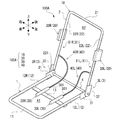
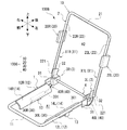
- FIG. 1 is a perspective view of a vehicle seat provided with the airbag device according to the first embodiment.
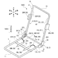
- FIG. 2 is a perspective view of the airbag device according to the first embodiment.
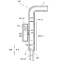
- FIG. 3 is a schematic configuration diagram of the airbag according to the first embodiment.
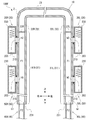
- FIG. 4 is a schematic configuration diagram for explaining the distribution pipe according to the first embodiment.
- FIG. 5 is a schematic configuration diagram for explaining the operation of the airbag device according to the first embodiment.
- FIG. 6 is a perspective view of the airbag device according to the first modification of the first embodiment.
- FIG. 7 is a perspective view of the airbag device according to the second modification of the first embodiment.
- FIG. 8 is a perspective view of the airbag device according to the third modification of the first embodiment.
- FIG. 1 is a perspective view of a vehicle seat provided with the airbag device according to the first embodiment.
- FIG. 2 is a perspective view of the airbag device according to the first embodiment.
- FIG. 3 is a schematic configuration diagram of the airbag according
- FIG. 9 is a perspective view of the airbag device according to the fourth modification of the first embodiment.
- FIG. 10 is a schematic configuration diagram for explaining the distribution pipe according to the modified example 5 of the first embodiment.
- FIG. 11 is a schematic configuration diagram for explaining the operation of the airbag device according to the fifth modification of the first embodiment.
- FIG. 12 is a schematic configuration diagram for explaining a distribution pipe according to a modification 6 of the first embodiment.
- FIG. 13 is a schematic configuration diagram of a vehicle seat provided with the airbag device according to the second embodiment.
- FIG. 14 is a perspective view of the airbag device according to the second embodiment.
- FIG. 1 is a perspective view of a vehicle seat S10 provided with the airbag device according to the first embodiment.
- the vehicle seat S10 is for the occupant of the vehicle to be seated.
- the front-rear direction (depth direction), the left-right direction (width direction), and the vertical direction (height direction) of the vehicle seat S10 are the occupants (seats) seated on the vehicle seat S10.
- the explanation will be given with reference to each direction of front-back, left-right, and up-down as seen from.
- the vehicle seat S10 has a seat cushion (seat surface portion) S1 that supports the occupant's buttocks and a seat back (backrest) that supports the occupant's back, corresponding to each part of the occupant's body. Part) S2 and a headrest S3 that supports the occupant's head are provided.
- the seat cushion S1 has a seat surface S11 on which an occupant sits.
- the seat back S2 is tiltably connected to the rear end of the seat cushion S1.
- the headrest S3 is connected to the upper end of the seat back S2 so as to be vertically movable.
- Reference numeral 10 shown in FIG. 1 is a seat frame forming the skeleton of the vehicle seat S10.
- the seat frame 10 is made of a metal material in this embodiment.
- Reference numeral P10 is a pad that covers the seat frame 10.
- the pad P10 is formed of, for example, urethane foam or the like.
- Reference numeral U10 is a skin material forming the outer surface of the vehicle seat S10.
- the skin material U10 is formed of an appropriate material such as cloth or leather.
- the vehicle seat S10 is formed by covering the seat frame 10 with the pad P10 and further covering the pad P10 with the skin material U10.
- the pad P10 includes a cushion pad P1 provided on the seat cushion S1 and a back pad P2 provided on the seat back S2. Further, the skin material U10 includes a skin material U1 provided on the seat cushion S1 and covering the cushion pad P1 and a skin material U2 provided on the seat back S2 and covering the back pad P2.
- the cushion C1 is formed by the cushion pad P1 and the skin material U1.
- the vehicle seat S10 includes an airbag device that inflates and deploys an airbag to restrain and protect an occupant when a vehicle collides.
- FIG. 2 is a perspective view of the airbag device 100 according to the present embodiment.
- the airbag device 100 includes a seat frame 10, an airbag 20, a gas generator 30, and a conduit 40.
- the airbag 20 is an airbag for the chest, is arranged on the seat back S2, and is deployed by supplying gas to protect the chest of the occupant.
- the airbag according to the technique of the present disclosure is not limited to the one for the chest.
- the gas generator 30 is arranged on the seat cushion S1 to generate gas supplied to the airbag 20. Details will be described later, but as shown in FIG.
- a part of the seat frame 10 is a distribution pipe X1 connected to the airbag so as to supply the gas generated by the gas generator 30 to the airbag 20. It is formed.
- the conduit 40 connects the gas generator 30 and the flow pipe X1 so as to guide the gas generated by the gas generator 30 to the flow pipe X1.
- the seat frame 10 includes a cushion frame 1, a back frame 2, a first connecting frame 3R, a second connecting frame 3L, and a reclining rod (rotating shaft portion) 4.
- the cushion frame 1 is a frame that forms the skeleton of the seat cushion S1.
- the cushion frame 1 includes a front frame 11, a first cushion side frame 12R, a second cushion side frame 12L, and a rear frame 13.
- the front frame 11 extends in the left-right direction to form the front end of the cushion frame 1.
- the first cushion side frame 12R extends rearward from the right end portion of the front frame 11 and forms the right end portion of the cushion frame 1.
- the second cushion side frame 12L extends rearward from the left end portion of the front frame 11 to form the left end end of the cushion frame 1.
- the first cushion side frame 12R and the second cushion side frame 12L are arranged on the seat frame 10 so as to be located on the side of the buttocks of the occupant seated on the vehicle seat S10.
- the buttocks of the occupant are positioned between the first cushion side frame 12R and the second cushion side frame 12L.
- the front frame 11, the first cushion side frame 12R, and the second cushion side frame 12L are formed into an integral tubular shape by bending a hollow metal pipe material into a U shape.
- the front frame 11, the first cushion side frame 12R, and the second cushion side frame 12L have a cylindrical cross section, but their cross-sectional shapes are not particularly limited.
- the rear frame 13 is provided behind the front frame 11 and extends in the left-right direction to connect the first cushion side frame 12R and the second cushion side frame 12L.
- the rear frame 13 is formed of, for example, sheet metal, and the right end portion is connected to the first cushion side frame 12R by welding or the like, and the left end portion is connected to the second cushion side frame 12L by welding or the like.
- the rear frame 13 also functions as a support member for supporting the gas generator 30.
- the cushion side frame 12R and the second cushion side frame 12L are simply referred to as the cushion side frame 12.
- the region surrounded by the cushion frame 1 is referred to as the first region A1.
- the first region A1 is specifically a region surrounded by the front frame 11, the first cushion side frame 12R, and the second cushion side frame 12L, which are portions of the cushion frame 1 that form the outer shape of the skeleton of the seat cushion S1. is there.
- the cushion frame 1 is provided with support members (not shown) such as springs, wires, etc. for supporting the seated person seated on the vehicle seat S10, for example, the first cushion side frame 12R and the second cushion side frame 12L.
- the cushion pad P1 may be placed on the support member.
- the back frame 2 is a frame that forms the skeleton of the seat back S2, and is formed in a tubular shape by bending a hollow metal pipe material into a U shape.
- the back frame 2 includes an upper frame 21, a first backside frame 22R, and a second backside frame 22L.
- the upper frame 21 extends in the left-right direction and forms the upper end of the back frame 2.
- a bracket (not shown) for inserting and attaching a pillar (not shown) of the headrest S3 is attached to the upper frame 21 by welding or the like.
- the first backside frame 22R extends downward from the right end portion of the upper frame 21 (that is, the seat cushion S1 side) to form the right end portion of the back frame 2.
- the second back side frame 22L extends downward from the left end portion of the upper frame 21 (that is, the seat cushion S1 side) to form the left end end of the back frame 2.
- the first backside frame 22R and the second backside frame 22L are arranged on the vehicle seat S10 so as to be located on the side of the back of the occupant seated on the vehicle seat S10. More specifically, the back of the occupant is positioned between the first backside frame 22R and the second backside frame 22L.
- the back frame 2 in the present embodiment has a cylindrical cross section, but the cross-sectional shape thereof is not particularly limited. In the following description, when the first backside frame 22R and the second backside frame 22L are described without distinction, they are simply referred to as the backside frame 22. As shown in FIG.
- a part of the backside frame 22 is formed as a distribution pipe X1, and has a function as a gas flow path in addition to a function as a skeleton of the vehicle seat S10. ..
- the details of the distribution pipe X1 will be described later.
- the region surrounded by the back frame 2 is referred to as the second region A2.
- the second region A2 is specifically a region surrounded by the upper frame 21, the first backside frame 22R, and the second backside frame 22L, which are portions of the back frame 2 that form the outer shape of the skeleton of the seat back S2. is there.
- the first connecting frame 3R and the second connecting frame 3L are members for connecting the cushion frame 1 and the back frame 2.
- the first connecting frame 3R and the second connecting frame 3L are provided apart from each other on the left and right sides.
- the connecting frame 3 is a back that is connected to the rear end of the cushion side frame 12 of the cushion frame 1 and extends rearward, and a back that is connected to the lower end of the back side frame 22 of the back frame 2 and extends downward.
- the cushion side connecting frame 31 is formed of, for example, sheet metal, and is connected to the cushion side frame 12 by welding or the like.
- the back side connecting frame 32 is formed of, for example, sheet metal, and is connected to the back side frame 22 by welding or the like.
- the cushion-side connecting frame 31 of the first connecting frame 3R and the rear end portions of the cushion-side connecting frame 31 of the second connecting frame 3L are connected by a reclining rod 4 extending in the left-right direction.
- the reclining rod 4 is a member that forms a rotation shaft of the back frame 2 for tilting the seat back S2, and is made of a metal pipe material having a hollow shape.
- the reclining rod 4 is connected to the cushion-side connecting frame 31 of the first connecting frame 3R by welding or the like with its right end penetrating the cushion-side connecting frame 31 of the first connecting frame 3R.
- the lower end of the back-side connecting frame 32 of the first connecting frame 3R is rotatably pivotally supported at a portion of the reclining rod 4 protruding to the right from the cushion-side connecting frame 31 of the first connecting frame 3R. ing.
- the reclining rod 4 is connected to the cushion-side connecting frame 31 of the second connecting frame 3L by welding or the like with its left end portion penetrating the cushion-side connecting frame 31 of the second connecting frame 3L.
- the lower end portion of the back side connecting frame 32 of the second connecting frame 3L is rotatably pivotally supported at the portion of the reclining rod 4 protruding to the left from the cushion side connecting frame 31 of the second connecting frame 3L. ing.
- the cushion frame 1 and the back frame 2 are connected so that the back frame 2 can rotate with respect to the cushion frame 1.
- Airbag As shown in FIG. 1, on the seat back S2 of the vehicle seat S10, one airbag 20 is arranged on each of the left and right sides corresponding to the chest of the occupant.
- the airbag 20 on the right side is referred to as the first airbag 20R
- the airbag 20 on the left side is referred to as the second airbag 20L, and these are not distinguished. In this case, it is simply referred to as an airbag 20.
- the airbag 20 is attached to the back frame 2 in the seat frame 10.
- the first airbag 20R is attached to the first backside frame 22R of the back frame 2
- the second airbag 20L is attached to the second backside frame 22L of the back frame 2.
- the airbag 20 is attached to the middle portion of the back side frame 22 in the back frame 2 in the vertical direction.
- the mounting position of the airbag 20 is not limited to these, and the airbag 20 may be mounted on the upper frame 21 of the back frame 2, for example.
- FIG. 3 is a schematic configuration diagram of the airbag 20.
- the airbag 20 is housed in the case 210, the mounting bracket 220 for mounting the case 210 to the back frame 2, and the case 210, and is expanded by the gas supplied from the gas generator 30.
- the airbag bag body 230 and the like are included.
- the case 210 includes the back plate 201 and the case body 202, and is formed in a box shape as a whole.
- the back plate 201 is, for example, a metal plate member, and is fastened and fixed to the back side frame 22 of the back frame 2 by a mounting bracket 220.
- the introduction hole 203 is formed in the back plate 201 as a through hole penetrating in the plate thickness direction.
- the introduction hole 203 is an opening for introducing a gas for expanding the airbag bag body into the inside of the case 210.
- the introduction hole 203 is formed in the back plate 201 at a position facing the back side frame 22 of the back frame 2.
- a sealing member 203a formed in an annular shape by an elastic material such as rubber is provided on the peripheral edge of the introduction hole 203 in the back plate 201.
- the seal member 203a may be vulcanized and adhered to the back plate 201, for example.
- the case body 202 of the case 210 is formed of, for example, resin or the like, and includes a side surface portion 2021 and a front surface portion 2022.
- the side surface portion 2021 stands upright from the back plate 201 and forms the side surface of the case 210.
- the front portion 2022 is connected to the tip of each side surface portion 2021 so as to face the back plate 201, and forms the front surface of the case 210.
- the case body 202 and the back plate 201 can be integrally fixed by an appropriate method. As shown in FIG. 1, in the vehicle seat S10, the surface of the front portion 2022 of the case body 202 is exposed to the outside from the opening formed in the skin material U2 of the seat back S2, and the surface and the surface of the skin material U2. It has become one.
- the airbag bag body 230 is housed in a folded state inside the case 210.
- the airbag bag body can be housed in the case 210 in a known folding mode.
- the airbag bag body may be folded by bellows folding, may be folded by roll folding, or may be folded by a combination of these.
- the gas generator 30 on the right side is referred to as a first gas generator 30R
- the gas generator 30 on the left side is referred to as a second gas generator 30L.
- the first gas generator 30R generates the gas supplied to the first airbag 20R.
- the second gas generator 30L generates the gas supplied to the second airbag 20L.
- the first gas generator 30R and the second gas generator 30L are arranged at intervals in the left-right direction (that is, the width direction of the vehicle seat S10), and are supported by the rear frame 13 of the cushion frame 1. .
- the gas generator 30 has a long tubular shape in the axial direction. More specifically, the gas generator 30 has a tubular shape in which the axial dimension is longer than the radial dimension. As shown in FIG. 2, the gas generator 30 is arranged in the first region A1 so that its axial direction coincides with the front-rear direction. An ejection hole 301 for ejecting gas is formed at the rear end of the gas generator 30.
- the gas generator 30 generates gas by operating under the control of an airbag ECU mounted on the vehicle.
- the method by which the gas generator according to the present disclosure generates gas is not particularly limited. Examples of the gas generator method include a pyro system that generates gas by burning a solid gas generator, a stored gas system that uses pressurized gas, and a hybrid system that combines a pyro system and a stored gas system.
- the conduit 40 is a tubular member through which gas can flow.
- the airbag device 100 includes two conduits 40 corresponding to the first gas generator 30R and the second gas generator 30L.
- the vessel 40 corresponding to the first gas generator 30R is referred to as the first vessel 40R
- the vessel 40 corresponding to the second gas generator 30L is referred to as the second vessel 40L, and when these are described without distinction, they are simply referred to.
- It is called a conduit 40.
- One end of the first conduit 40R is connected to the ejection hole 301 of the first gas generator 30R, and the other end is connected to the lower end portion 221 of the first backside frame 22R of the back frame 2.
- One end of the second conduit 40L is connected to the ejection hole 301 of the second gas generator 30L, and the other end is connected to the lower end portion 221 of the second backside frame 22L of the back frame 2.
- the conduit 40 is made of a material having at least a part of flexibility and can be bent in any direction. As a result, the rotation of the back frame 2 with respect to the cushion frame 1 due to the tilting of the seat back S2 is not hindered by the conduit 40 connecting the gas generator 30 and the back frame 2.
- FIG. 4 is a schematic configuration diagram for explaining the distribution pipe according to the first embodiment. In FIG. 4, a cross section orthogonal to the front-rear direction (depth direction) is shown.
- a part of the first backside frame 22R of the back frame 2 is formed as a first distribution pipe X1R for supplying the gas from the first gas generator 30R to the first airbag 20R.
- a part of the second backside frame 22L of the back frame 2 is formed as a second distribution pipe X1L for supplying the gas from the second gas generator 30L to the second airbag 20L.
- the distribution pipe X1 utilizes the hollow shape of the back side frame 22 of the back frame 2 as a gas flow path.
- the distribution pipe X1 is formed by a portion of the backside frame 22 that is continuous from the lower end portion 221 to which the conduit 40 is connected to the portion to which the airbag 20 is attached.
- an inflow hole h1 communicating with the conduit 40 is formed in the lower end portion 221 of the backside frame 22.
- the flow pipe X1 and the pipe 40 are connected so that the gas flowing from the pipe 40 flows into the flow pipe X1 through the inflow hole h1.
- a supply hole h2 communicating with the introduction hole 203 is formed at a position of the backside frame 22 where the airbag 20 is attached at a position corresponding to the introduction hole 203 of the airbag 20.
- the distribution pipe X1 and the airbag 20 are connected so that the gas flowing in the distribution pipe X1 is supplied to the airbag 20 through the supply hole h2 and the introduction hole 203.
- the flow pipe X1 forms a part of the flow path for the gas generated by the gas generator 30 to flow from the gas generator 30 to the airbag 20.
- the flow path formed by the flow pipe X1 is referred to as a flow path F1
- the flow path formed by the conduit 40 is referred to as a flow path F2.
- reference numeral d1 in FIG. 4 indicates the inner diameter of the backside frame 22, that is, the inner diameter of the flow pipe X1.
- reference numeral d2 indicates the inner diameter of the conduit 40.
- d1 is set to have a size larger than d2.
- the cross-sectional area of the gas flow path F1 in the flow pipe X1 is larger than the cross-sectional area of the flow path F2 in the conduit 40.
- the cross-sectional area referred to here refers to the area of the cross section orthogonal to the gas flow direction, and specifically, is the cross section orthogonal to the extension direction of the distribution pipe X1.
- a first partition wall 23R that vertically separates the space in the first backside frame 22R is provided inside the first backside frame 22R.
- the first partition wall 23R is a metal disk member having an outer diameter equal to the inner diameter of the first backside frame 22R, and is a first at a position above the supply hole h2 formed in the first backside frame 22R. It is welded all around the inner wall of the backside frame 22R.
- a second partition wall 23L that vertically separates the space in the second backside frame 22L is provided inside the second backside frame 22L.
- the second partition wall 23L is a metal disk member having an outer diameter equal to the inner diameter of the second backside frame 22L, and is a second partition wall at a position above the supply hole h2 formed in the second backside frame 22L. It is welded all around the inner wall of the backside frame 22L.
- the ends (upper ends) of the first distribution pipe X1R and the second distribution pipe X1L are defined, and the first distribution pipe X1R and the second distribution pipe X1L are separated from each other.
- it is prevented that the gas from the first gas generator 30R that has flowed into the first distribution pipe X1R is supplied to the second airbag 20L through the upper frame 21.
- the gas from the second gas generator 30L flowing into the second distribution pipe X1L is supplied to the first airbag 20R through the upper frame 21.
- FIG. 5 is a schematic configuration diagram for explaining the operation of the airbag device 100 according to the first embodiment.
- the airbag ECU detects a vehicle collision based on a signal from a collision sensor (not shown)
- an operating current ignition current
- the gas generator 30 operates, and gas is ejected from the ejection hole 301.
- the gas ejected from the ejection hole 301 flows into the conduit 40.
- the gas that has flowed into the conduit 40 flows through the conduit 40 and flows into the flow pipe X1 through the inflow hole h1.
- the gas that has flowed into the distribution pipe X1 flows upward along the extending direction (axial direction) of the backside frame 22 in the distribution pipe X1, and flows into the case 210 through the supply hole h2 and the introduction hole 203.
- the gas generated by the gas generator 30 is supplied to the airbag 20.
- the airbag bag body 230 in the folded state expands in the case 210.
- the case 210 is cleaved by the expansion pressure of the airbag bag body 230, and the airbag bag body 230 expands and jumps out of the case 210 to the outside.
- the first airbag 20R and the second airbag 20L are deployed, and the chest of the occupant is restrained. As a result, the occupants are protected.
- the airbag device 100 operates the first gas generator 30R and the second gas generator 30L independently, and the first airbag 20R and the second airbag 20L are independently operated according to how an impact is applied. It may be expanded.
- the airbag device 100 adopts a structure in which the airbag 20 is arranged on the seat back S2 and the gas generator 30 is arranged on the seat cushion S1 among the vehicle seats S10. There is. According to this, by not arranging the gas generator 30 in the seat back S2, the seat back can be made thinner as compared with the conventional airbag device in which both the airbag and the gas generator are arranged in the seat back. it can. Further, due to the structure of the seat cushion, the space in which the parts can be arranged is wider than that of the seat back, so that the gas generator can be arranged without significantly increasing the size of the seat cushion.
- a part of the back frame 2 in the seat frame 10 is connected to the airbag 20 so as to supply the gas generated by the gas generator 30 to the airbag 20. It is formed as X1. That is, the airbag device 100 forms a part of the flow path for supplying gas from the gas generator 30 arranged in the seat cushion S1 to the airbag 20 arranged in the seat back S2 by the back frame 2. ing.
- the seat frame for forming the skeleton of the vehicle seat usually has a sufficient thickness (cross-sectional area) in order to secure the strength required as a structure.
- the seat back S2 can be made thinner and lighter.
- the distribution pipe X1 is formed by only a part of the back side frame 22 of the back frame 2, but the technique of the present disclosure is not limited to this.
- the part of the seat frame that forms the flow pipe can be changed according to the position where the airbag is attached and which part of the occupant is to be protected.
- the distribution pipe may be a part of the seat frame and may be formed by a part including at least a part of the back frame.
- the distribution pipe X1 may include a part of the upper frame 21, a part of the back frame 2, a part of the reclining rod 4, and a part of the cushion frame 1.
- the airbag 20 is directly attached to the back frame 2
- the airbag does not have to be directly attached to the back frame.
- the airbag may be attached to a member different from the back frame, and the distribution pipe and the airbag may be connected by a pipe member or the like.
- the airbag 20 is connected to the middle portion of the backside frame 22 forming the distribution pipe X1, and the conduit 40 is connected to the lower end portion 221 of the backside frame 22. .. That is, the conduit 40 that guides the gas from the gas generator 30 to the circulation pipe X1 is located in the distribution pipe X1 closer to the seat cushion S1 where the gas generator 30 is arranged than the portion to which the airbag 20 is connected. It is connected. As a result, the distance between the gas generator 30 and the portion of the flow pipe X1 where the conduit 40 is connected can be shortened, and the length of the conduit 40 can be shortened.
- the gas can be guided to the distribution pipe X1 at an early stage, and the gas can be quickly supplied to the airbag 20.
- the airbag 20 can be deployed more quickly.
- the vessel 40 can be shortened, the vessel 40 can be easily handled in the seat, and the entanglement of the vessel 40 can be suppressed. Further, it can contribute to the reduction of material cost and the weight reduction of the sheet itself.
- the flow pipe X1 includes the lower end portion 221 which is the end portion of the back frame 2 on the seat cushion S1 side, and the conduit 40 is connected to the lower end portion 221. That is, in the back frame 2, the conduit 40 is connected to the portion closest to the seat cushion S1. Therefore, the length of the conduit 40 can be further shortened.
- the cross-sectional area of the gas flow path F1 in the flow pipe X1 is set to be larger than the cross-sectional area of the flow path F2 in the conduit 40.
- the flow rate and flow velocity of the gas in the flow pipe X1 can be made larger than the flow rate and flow velocity of the gas in the conduit 40.
- the gas can be supplied to the airbag 20 more quickly, and the airbag 20 can be deployed more quickly.
- the gas can be guided to the flow pipe X1 having a large flow rate and flow velocity of the flowing gas at an early stage, so that the airbag 20 can be deployed even more quickly.
- FIG. 6 is a perspective view of the airbag device 100A according to the first modification of the first embodiment.
- the conduit 40 is connected to the portion of the distribution pipe X1 from the second region A2 side. That is, in the airbag device 100A according to the first modification, the gas generator 30 is arranged in the first region A1 which is the region surrounded by the cushion frame 1, and the conduit 40 is the second region surrounded by the back frame 2.
- the structure is such that the area A2 side is connected to the distribution pipe X1. Therefore, the conduit 40 can connect the gas generator 30 and the flow pipe X1 without going out of the region including the first region A1 and the second region A2.
- the conduit 40 can be housed inside the seat frame 10. As a result, the vehicle seat S10 can be made compact.
- FIG. 7 is a perspective view of the airbag device 100B according to the second modification of the first embodiment.
- the back frame 2 of the airbag device 100B includes a first lower frame 24R extending leftward from the lower end portion 221 of the first backside frame 22R toward the second backside frame 22L, and a second lower frame 24R. It further includes a second lower frame 24L extending to the right from the lower end portion 221 of the backside frame 22L toward the first backside frame 22R.
- the first lower frame 24R has a hollow shape continuous with the first backside frame 22R
- the second lower frame 24L has a hollow shape continuous with the second backside frame 22L.
- the tips of the first lower frame 24R and the second lower frame 24L are both closed and separated from each other.
- the first lower frame 24R and the second lower frame 24L are simply referred to as the lower frame 24.
- the seat frame 10 does not have the reclining rod 4, and the back side connecting frame 32 of the connecting frame 3 is rotatably supported by the cushion side connecting frame 31.
- the first conduit 40R is connected to the first lower frame 24R
- the second conduit 40L is connected to the second lower frame 24L.
- the first distribution pipe X1R of the second modification is formed by a portion of the back frame 2 that is continuous from a portion to which the first conduit 40R is connected to a portion to which the first airbag 20R is connected.
- the second flow pipe X1L is formed by a portion of the back frame 2 that is continuous from a portion to which the second conduit 40L is connected to a portion to which the second airbag 20L is connected.
- the lower frame 24 is arranged near the rotation axis of the back frame 2 and inside the outer shape of the skeleton formed by the vehicle seat S10.
- the length of the conduit 40 can be further shortened.
- the gas can be guided to the distribution pipe X1 at an early stage, and the gas can be quickly supplied to the airbag 20.
- the airbag 20 can be deployed more quickly.
- FIG. 8 is a perspective view of the airbag device 100C according to the third modification of the first embodiment.
- a part of the back frame 2 which is a part of the seat frame 10 and forms the skeleton of the seat back S2 and the rotation axis of the seat back S2 are formed.
- a portion including a part of the reclining rod 4 is formed as a distribution pipe X1.
- the reclining rod 4 includes a first rod 41R extending leftward from the lower end portion 221 of the first backside frame 22R of the back frame 2 toward the second backside frame 22L, and a second backside frame 22L. It has a second rod 41L extending to the right from the lower end portion 221 of the rod toward the first backside frame 22R.
- the first rod 41R has a hollow shape continuous with the first backside frame 22R
- the second rod 41L has a hollow shape continuous with the second backside frame 22L.
- the tips of the first rod 41R and the second rod 41L are both closed and separated from each other.
- the connecting frame 3 does not have the back side connecting frame 32, and the reclining rod 4 integrally formed with the back frame 2 is rotatably supported by the cushion side connecting frame 31. ..
- the first conduit 40R is connected to the first rod 41R, and the second conduit 40L is connected to the second rod 41L.
- the first flow pipe X1R of the third modification is formed by a portion of the seat frame 10 that is continuous from the portion connected to the first conduit 40R to the portion connected to the first airbag 20R, and is formed by the second flow pipe X1L. Is formed by a portion of the seat frame 10 that is continuous from a portion to which the second conduit 40L is connected to a portion to which the second airbag 20L is connected.
- the airbag device 100C according to the third modification has a configuration in which the gas generator 30 arranged in the seat cushion S1 and the reclining rod 4 which is the axis of rotation of the back frame 2 with respect to the seat cushion S1 are connected by a conduit 40. There is.
- the length of the conduit 40 can be further shortened.
- the gas can be guided to the distribution pipe X1 at an early stage, and the gas can be quickly supplied to the airbag 20.
- the airbag 20 can be deployed more quickly.
- a part of the seat frame 10 in which the entire reclining rod 4 is added to a part of the back frame 2 is formed as a distribution pipe X1.
- a part of the seat frame 10 including at least a part of the back frame 2 and at least a part of the reclining rod 4 may be formed as the distribution pipe X1.
- FIG. 9 is a perspective view of the airbag device 100D according to the fourth modification of the first embodiment.
- a part of the seat frame 10 including a part of the back frame 2 and a part of the cushion frame 1 is formed as a distribution pipe X1. There is.
- the seat frame 10 of the airbag device 100D has a first connecting tube 5R and a second connecting tube 5L that connect the cushion frame 1 and the back frame 2.
- the first connecting tube 5R connects the rear end portion 121 of the first cushion side frame 12R of the cushion frame 1 and the lower end portion 221 of the first back side frame 22R of the back frame 2.
- the second connecting tube 5L connects the rear end portion 121 of the second cushion side frame 12L of the cushion frame 1 and the lower end portion 221 of the second back side frame 22L of the back frame 2.
- the connecting tube 5R and the second connecting tube 5L are simply referred to as the connecting tube 5.
- the connecting tube 5 is a tubular member through which gas can flow.
- the connecting tube 5 connects the rear end portion 121 of the cushion side frame 12 and the lower end portion 221 of the back side frame 22 so as to guide the gas flowing in the cushion side frame 12 into the back side frame 22.
- the connecting tube 5 is formed of at least a part of a flexible material so as not to hinder the rotation of the back frame 2 with respect to the cushion frame 1 due to the tilting of the seat back S2, and is bent in an arbitrary direction. be able to.
- the conduit 40 is connected to the cushion side frame 12 of the cushion frame 1. More specifically, the first conduit 40R connects the first gas generator 30R and the first cushion side frame 12R, and the second conduit 40L connects the second gas generator 30L and the second cushion side frame 12L. ..
- the first flow pipe X1R of the fourth modification is formed by a portion of the seat frame 10 that is continuous from the portion connected to the first conduit 40R to the portion connected to the first airbag 20R, and is formed by the second flow pipe X1L. Is formed by a portion of the seat frame 10 that is continuous from a portion to which the second conduit 40L is connected to a portion to which the second airbag 20L is connected.
- the gas guided from the gas generator 30 to the flow pipe X1 by the conduit 40 is supplied to the airbag 20 through the cushion side frame 12, the connecting tube 5, and the back side frame 22.
- the airbag device 100D according to the fourth modification has a configuration in which the gas generator 30 arranged in the seat cushion S1 and the cushion frame 1 forming the skeleton of the seat cushion S1 are connected by a conduit 40.
- the length of the conduit 40 can be further shortened.
- the gas can be guided to the distribution pipe X1 at an early stage, and the gas can be quickly supplied to the airbag 20.
- the airbag 20 can be deployed more quickly.
- FIG. 10 is a schematic configuration diagram for explaining the distribution pipe according to the modified example 5 of the first embodiment.
- FIG. 11 is a schematic configuration diagram for explaining the operation of the airbag device 100E according to the fifth modification of the first embodiment.
- the airbag bag body 230 of the airbag 20 according to the modified example 5 is divided into a first expansion portion 230a and a second expansion portion 230b by a partition member 2301 provided inside the airbag bag body 230.
- the first expansion portion 230a is a portion of the airbag bag body corresponding to the chest of the occupant, and protects the chest of the occupant by expanding due to the supply of gas.
- the second expansion portion 230b is a portion of the airbag bag body corresponding to the waist portion of the occupant, and protects the waist portion of the occupant by expanding due to the supply of gas.
- the second expansion portion 230b expands at a position below the position where the first expansion portion 230a expands. That is, the airbag 20 according to the modified example 5 also functions as an airbag for the chest and an airbag for the waist.
- a first introduction hole 204 and a second introduction hole 205 are formed in the case 210 of the airbag 20 according to the modified example 5.
- the first introduction hole 204 is an opening for introducing a gas for expanding the first expansion portion 230a into the case 210.
- the second introduction hole 205 is an opening for introducing a gas for expanding the second expansion portion 230b into the case 210.
- the flow pipe X1 communicates with the first introduction hole 204 to supply gas to the first expansion portion 230a, and communicates with the second introduction hole 205.
- a second supply hole h4 for supplying gas to the second expansion portion 230b is formed.
- the second supply hole h4 is formed in the distribution pipe X1 at a portion below the first supply hole h3, that is, at a portion located upstream of the gas flow from the first supply hole h3.
- the second expansion portion 230b can be expanded before the first expansion portion 230a.
- the chest of the occupant is restrained by the expansion of the first expansion portion 230a.
- the airbag device 100E according to the modified example 5 by restraining the occupant's body in the order from the waist to the chest, the occupant's body swing is suitably suppressed in the event of a vehicle collision, and thus the occupant is more preferably protected. can do.
- the size of the second supply hole h4 may be larger than that of the first supply hole h3. As a result, a larger amount of gas is supplied to the second expansion portion 230b in a shorter time than to the first expansion portion 230a, and the second expansion portion 230b expands preferentially.
- FIG. 12 is a schematic configuration diagram for explaining a distribution pipe according to a modification 6 of the first embodiment.
- the airbag device 100F according to the modified example 6 is deployed by supplying gas in addition to the first airbag 20R and the second airbag 20L as an airbag for the chest, so that the waist of the occupant
- a third airbag 50R and a fourth airbag 50L for the lumbar region are provided.
- the third airbag 50R for the lumbar region is attached to the first back side frame 22R of the back frame 2 in the seat frame 10
- the fourth airbag 50L for the lumbar region is the back in the seat frame 10. It is attached to the second backside frame 22L of the frame 2.
- the third airbag 50R for the lumbar region and the fourth airbag 50L for the lumbar region are simply referred to as the airbag 50 for the lumbar region.
- the lumbar airbag 50 has the same structure as the chest airbag 20, and the position where it is attached to the seat frame 10 is different from that of the chest airbag 20. More specifically, the lumbar airbag 50 is attached to a position below the chest airbag 20 in the distribution pipe X1 formed by a part of the back side frame 22 of the back frame 2. .. Therefore, the lumbar airbag 50 expands at a position below the position where the chest airbag 20 expands.
- the lumbar airbag 50 is located at a position corresponding to the introduction hole 203 of the lumbar airbag 50 at the portion of the circulation pipe X1 to which the lumbar airbag 50 is attached.
- a supply hole for the lumbar region that communicates with the introduction hole 203 is formed.
- the air flowing through the circulation pipe X1 and the lumbar portion is supplied to the lumbar airbag 50 through the supply hole for the lumbar region and the introduction hole 203 of the airbag 50 for the lumbar region. It is connected to the bag 50.
- the lumbar supply hole is located above the inflow hole h1 in which the gas flowing from the conduit 40 flows in the flow pipe X1, and is for the chest where the gas flows out to the chest airbag 20. It is formed at a position below the supply hole h2. That is, in the distribution pipe X1, the portion to which the waist airbag 50 is connected is located upstream of the portion to which the chest airbag 20 is connected to the gas flow.
- the airbag 50 for the waist can be deployed before the airbag 20 for the chest.
- the airbag device 100F according to the modified example 6 is operated, first, the waist portion of the occupant is restrained by deploying the airbag 50 for the waist portion. The chest airbag 20 is then deployed to constrain the occupant's chest.
- the occupant's body is restrained in the order from the waist to the chest in the same manner as the airbag device 100E according to the modification 5, so that the occupant's body swings at the time of a vehicle collision. It can be suitably suppressed, and thus the occupants can be more preferably protected.
- the airbag 20 for the chest and the airbag 50 for the waist are separately provided. In other words, since the protection of the chest and the protection of the lumbar region are realized by separate airbags, it is sufficient to install the airbags at the positions corresponding to the chest and the lumbar region of the occupant. Therefore, the airbag can be miniaturized and the amount of gas required can be reduced.
- the entire airbag device can be miniaturized.
- the size of the lumbar supply hole h5 may be larger than that of the chest supply hole h2.
- a larger amount of gas is supplied to the lumbar airbag 50 in a shorter time than to the chest airbag 20, and the lumbar airbag 50 expands preferentially.
- FIG. 13 is a schematic configuration diagram of a vehicle seat S10G provided with the airbag device according to the second embodiment.
- a cross section orthogonal to the front-rear direction (depth direction) is shown.
- the alternate long and short dash line indicated by reference numeral M1 represents an occupant.
- FIG. 14 is a perspective view of the airbag device 100G according to the second embodiment.
- the differences between the vehicle seat S10 and the airbag device 100 according to the first embodiment described with reference to FIGS. 1 to 5 will be mainly described, and the vehicle seat S10 and the airbag device 100 will be described. Detailed explanation is omitted for the same points as above.
- the gas generator 30 is attached along the cushion side frame 12 of the back frame 2 in the seat frame 10. More specifically, the first gas generator 30R and the second gas generator 30L are arranged in the first region A1, and the longitudinal direction (axial direction) thereof is the direction in which the cushion side frame 12 extends (that is, that is, the axial direction). It is provided so as to coincide with the vehicle seat S10 in the front-rear direction). Further, as shown in FIG. 13, the cushion frame 1 of the airbag device 100G includes a first cover portion 14R and a second gas generator 30L that cover the first gas generator 30R from the seat surface S11 side of the seat cushion S1.
- a second cover portion 14L that covers the seat cushion S1 from the seat surface S11 side is provided.
- the cover portion 14 is made of a metal material, has an arcuate cross section that is substantially convex on the upper side (seat surface S11 side), and extends in the front-rear direction (depth direction).
- the side edge of the cover portion 14 is connected to the cushion side frame 12 of the cushion frame 1 by welding or the like.
- the cushion C1 is attached to the cushion frame 1 of the airbag device 100G, and the cushion frame 1 is covered with the cushion C1 to form the seat cushion S1.
- the gas generator 30 is covered from the seat surface S11 side by the cover portion 14, the gas generator 30 is protected from the load due to the seating of the occupant.
- the gas generator 30 is attached along the cushion side frame 12, the first gas generator 30R, the second gas generator 30L, the first cover portion 14R, and the second cover portion 14L are also cushion side. Similar to the frame 12, the occupant M1 seated on the vehicle seat S10 is located on the side of the buttocks H1.
- the buttock H1 of the occupant M1 is located between the first gas generator 30R and the first cover portion 14R and the second gas generator 30L and the second cover portion 14L.
- the cushion C1 is separated from the first side portion C11R, which is a region covering the first cover portion 14R, with respect to the first side portion C11R in the left-right direction (width direction). It is divided into a second side portion C11L which is a region covering the second cover portion 14L and a seating portion C12 which is a region sandwiched between the first side portion C11R and the second side portion C11L.
- the cushion C1 is a region that supports the buttocks H1 of the occupant M1 and is supported from below by the spring SP1. Further, in the vehicle seat S10G, the first cover portion 14R is covered by the first side portion C11R to form the first holding portion HD1R, and the second cover portion 14L is covered by the second side portion C11L.
- the second holding portion HD1L is formed in the above. Since the first cover portion 14R and the second cover portion 14L are located at positions sandwiching the buttock portion H1 of the occupant M1 from the left-right direction of the vehicle seat S10G, the first holding portion HD1R and the second holding portion HD1L are the occupant's side buttock portions. It is formed so as to hold SH1 from both sides in the left-right direction.
- the seat back S2 can be made thinner by arranging the gas generator 30 on the seat cushion S1 of the vehicle seat S10G. Further, since a part of the back frame 2 in the seat frame 10 is formed as the flow pipe X1, gas can be quickly supplied to the airbag 20 and the airbag 20 can be quickly deployed. It can also contribute to the reduction of material cost and the weight reduction of the sheet itself. Further, by using a part of the back frame 2 for forming the skeleton of the seat back S2 as the distribution pipe X1, the seat back S2 can be made thinner.
- the first holding portion HD1R and the second holding portion HD1L for holding the side buttock portion SH1 of the occupant M1 from both left and right directions (width directions) of the vehicle seat S are formed. By doing so, the holdability of the vehicle seat S10G can be improved.
- the cushion C1 is set so that the thickness T1 of the first side portion C11R and the second side portion C11L is thinner than the thickness T2 of the seating portion C12. According to this, while giving appropriate flexibility and elasticity to the seating portion C12 by making the seating portion C12 relatively thick, the first side portion C11R and the second side portion C11L are relatively thin. By doing so, the first holding portion HD1R and the second holding portion HD1L can be hardened. As a result, the side buttock SH1 of the occupant M1 can be held more firmly, and the holdability of the vehicle seat S10G can be further improved.
- the first gas generator 30R and the second gas generator 30L extend in the direction in which the cushion side frame 12 extends together with the first cover portion 14R and the second cover portion 14L (that is, the vehicle seat S10G). It is attached so as to extend in the front-back direction of.
- the first holding portion HD1R and the second holding portion HD1L can be lengthened in the front-rear direction (depth direction). Therefore, the range held by the first holding portion HD1R and the second holding portion HD1L in the side buttock portion SH1 of the occupant M1 can be widened. As a result, the holdability of the vehicle seat S10G can be further improved.
Landscapes
- Engineering & Computer Science (AREA)
- Mechanical Engineering (AREA)
- Physics & Mathematics (AREA)
- Fluid Mechanics (AREA)
- Aviation & Aerospace Engineering (AREA)
- Transportation (AREA)
- Air Bags (AREA)
- Seats For Vehicles (AREA)
Priority Applications (3)
| Application Number | Priority Date | Filing Date | Title |
|---|---|---|---|
| CN202080080772.4A CN114746313A (zh) | 2019-11-22 | 2020-10-12 | 气囊装置以及车辆用座椅 |
| US17/778,117 US11926278B2 (en) | 2019-11-22 | 2020-10-12 | Airbag device and vehicle seat |
| DE112020005734.8T DE112020005734T5 (de) | 2019-11-22 | 2020-10-12 | Airbagvorrichtung und Fahrzeugsitz |
Applications Claiming Priority (2)
| Application Number | Priority Date | Filing Date | Title |
|---|---|---|---|
| JP2019-211819 | 2019-11-22 | ||
| JP2019211819A JP7446790B2 (ja) | 2019-11-22 | 2019-11-22 | エアバッグ装置、及び車両用シート |
Publications (1)
| Publication Number | Publication Date |
|---|---|
| WO2021100355A1 true WO2021100355A1 (ja) | 2021-05-27 |
Family
ID=75963885
Family Applications (1)
| Application Number | Title | Priority Date | Filing Date |
|---|---|---|---|
| PCT/JP2020/038494 Ceased WO2021100355A1 (ja) | 2019-11-22 | 2020-10-12 | エアバッグ装置、及び車両用シート |
Country Status (5)
| Country | Link |
|---|---|
| US (1) | US11926278B2 (https=) |
| JP (2) | JP7446790B2 (https=) |
| CN (1) | CN114746313A (https=) |
| DE (1) | DE112020005734T5 (https=) |
| WO (1) | WO2021100355A1 (https=) |
Families Citing this family (7)
| Publication number | Priority date | Publication date | Assignee | Title |
|---|---|---|---|---|
| JP7324112B2 (ja) * | 2019-10-08 | 2023-08-09 | 株式会社ダイセル | シートフレームインフレータおよびエアバッグ装置 |
| JP7495221B2 (ja) * | 2019-11-22 | 2024-06-04 | 株式会社ダイセル | エアバッグ装置 |
| JP7377129B2 (ja) * | 2020-02-21 | 2023-11-09 | 株式会社ダイセル | 連結構造、エアバッグ装置、及び車両用シート |
| JP7498048B2 (ja) * | 2020-07-14 | 2024-06-11 | 株式会社ダイセル | 車両用シート、及び乗員拘束装置 |
| JP7157834B2 (ja) * | 2021-01-29 | 2022-10-20 | 本田技研工業株式会社 | 乗物用シート |
| JP7242723B2 (ja) * | 2021-01-29 | 2023-03-20 | 本田技研工業株式会社 | 乗物用シート |
| CN116811781B (zh) * | 2023-06-30 | 2026-04-03 | 岚图汽车科技股份有限公司 | 一种集成智能气囊座椅 |
Citations (8)
| Publication number | Priority date | Publication date | Assignee | Title |
|---|---|---|---|---|
| JPS4717316U (https=) * | 1971-03-26 | 1972-10-28 | ||
| JPS60234037A (ja) * | 1984-05-04 | 1985-11-20 | Daihatsu Motor Co Ltd | 着座者の保護装置 |
| US6425602B1 (en) * | 2000-03-16 | 2002-07-30 | Trw Inc. | Vehicle safety seat with fluid manifold |
| JP2003285709A (ja) * | 2002-03-29 | 2003-10-07 | Honda Motor Co Ltd | サイドエアバッグ装置 |
| JP2004090906A (ja) * | 2002-07-08 | 2004-03-25 | Honda Motor Co Ltd | サイドエアバッグ装置 |
| JP2007098991A (ja) * | 2005-09-30 | 2007-04-19 | Toyoda Gosei Co Ltd | サイドエアバッグ装置 |
| JP2007276599A (ja) * | 2006-04-05 | 2007-10-25 | Takata Corp | 車両シート、車両、エアバッグモジュール |
| JP2018090224A (ja) * | 2016-12-07 | 2018-06-14 | トヨタ自動車株式会社 | シートベルト内蔵車両用シート |
Family Cites Families (21)
| Publication number | Priority date | Publication date | Assignee | Title |
|---|---|---|---|---|
| JPS6053613U (ja) * | 1983-09-22 | 1985-04-15 | 池田物産株式会社 | 空調シ−ト |
| JPH081982Y2 (ja) | 1990-02-23 | 1996-01-24 | マツダ株式会社 | 車体側部のエネルギ吸収構造 |
| JPH09136595A (ja) * | 1995-11-15 | 1997-05-27 | Tokai Rika Co Ltd | 側突用エアバッグ装置 |
| US5913536A (en) * | 1996-02-07 | 1999-06-22 | Trw Vehicle Safety System Inc. | Air bag module |
| US5779263A (en) * | 1997-01-21 | 1998-07-14 | Alliedsignal Inc. | Integrated side impact air bag system within a seat structure |
| FR2770815B1 (fr) * | 1997-11-13 | 2000-05-19 | Allibert Ind | Dispositif de protection a coussin gonflable, pour vehicule |
| JP3754640B2 (ja) | 2001-10-02 | 2006-03-15 | 本田技研工業株式会社 | エアバッグ装置 |
| JP4734933B2 (ja) * | 2004-02-27 | 2011-07-27 | タカタ株式会社 | 車両乗員保護システムおよびインフレータ |
| JP2006199271A (ja) * | 2004-12-24 | 2006-08-03 | Tkj Kk | 乗員拘束装置 |
| JP2007137181A (ja) | 2005-11-16 | 2007-06-07 | Takata Corp | エアベルト装置 |
| JP2008037280A (ja) | 2006-08-07 | 2008-02-21 | Takata Corp | シート取付乗員拘束装置 |
| JP2008201298A (ja) | 2007-02-21 | 2008-09-04 | Toyota Motor Corp | 車両用サイドエアバッグ装置 |
| JP5716659B2 (ja) | 2011-12-27 | 2015-05-13 | トヨタ自動車株式会社 | 車両用シート及び自動車 |
| US9409504B2 (en) * | 2013-01-24 | 2016-08-09 | Ford Global Technologies, Llc | Flexible seatback system |
| US11104287B2 (en) * | 2016-12-05 | 2021-08-31 | Autoliv Development Ab | Side air bag device |
| US10471919B2 (en) | 2017-07-21 | 2019-11-12 | Ford Global Technologies, Llc | Vehicle airbag system |
| US10829077B2 (en) * | 2019-03-07 | 2020-11-10 | Ford Global Technologies, Llc | Vehicle seat side airbag bracket |
| JP7222110B2 (ja) * | 2019-09-23 | 2023-02-14 | オートリブ ディベロップメント エービー | エアバッグ装置及び車両用シート |
| KR102675827B1 (ko) * | 2019-10-04 | 2024-06-18 | 아우토리브 디벨롭먼트 아베 | 에어백 장치 및 차량용 시트 |
| KR102729838B1 (ko) * | 2020-02-16 | 2024-11-14 | 아우토리브 디벨롭먼트 아베 | 에어백 장치 및 차량용 시트 |
| US11180102B1 (en) * | 2020-08-12 | 2021-11-23 | Ford Global Technologies, Llc | Side airbag assembly |
-
2019
- 2019-11-22 JP JP2019211819A patent/JP7446790B2/ja active Active
-
2020
- 2020-10-12 US US17/778,117 patent/US11926278B2/en active Active
- 2020-10-12 CN CN202080080772.4A patent/CN114746313A/zh active Pending
- 2020-10-12 DE DE112020005734.8T patent/DE112020005734T5/de active Pending
- 2020-10-12 WO PCT/JP2020/038494 patent/WO2021100355A1/ja not_active Ceased
-
2024
- 2024-02-28 JP JP2024028375A patent/JP7686105B2/ja active Active
Patent Citations (8)
| Publication number | Priority date | Publication date | Assignee | Title |
|---|---|---|---|---|
| JPS4717316U (https=) * | 1971-03-26 | 1972-10-28 | ||
| JPS60234037A (ja) * | 1984-05-04 | 1985-11-20 | Daihatsu Motor Co Ltd | 着座者の保護装置 |
| US6425602B1 (en) * | 2000-03-16 | 2002-07-30 | Trw Inc. | Vehicle safety seat with fluid manifold |
| JP2003285709A (ja) * | 2002-03-29 | 2003-10-07 | Honda Motor Co Ltd | サイドエアバッグ装置 |
| JP2004090906A (ja) * | 2002-07-08 | 2004-03-25 | Honda Motor Co Ltd | サイドエアバッグ装置 |
| JP2007098991A (ja) * | 2005-09-30 | 2007-04-19 | Toyoda Gosei Co Ltd | サイドエアバッグ装置 |
| JP2007276599A (ja) * | 2006-04-05 | 2007-10-25 | Takata Corp | 車両シート、車両、エアバッグモジュール |
| JP2018090224A (ja) * | 2016-12-07 | 2018-06-14 | トヨタ自動車株式会社 | シートベルト内蔵車両用シート |
Also Published As
| Publication number | Publication date |
|---|---|
| JP2024052873A (ja) | 2024-04-12 |
| JP7686105B2 (ja) | 2025-05-30 |
| US11926278B2 (en) | 2024-03-12 |
| CN114746313A (zh) | 2022-07-12 |
| JP2021079927A (ja) | 2021-05-27 |
| US20220410833A1 (en) | 2022-12-29 |
| JP7446790B2 (ja) | 2024-03-11 |
| DE112020005734T5 (de) | 2022-09-15 |
Similar Documents
| Publication | Publication Date | Title |
|---|---|---|
| JP7446790B2 (ja) | エアバッグ装置、及び車両用シート | |
| JP6856482B2 (ja) | サイドエアバッグ装置を搭載した車両用シート及びサイドエアバッグ装置 | |
| JP4952422B2 (ja) | サイドエアバッグ装置 | |
| JP6748294B2 (ja) | 乗員保護装置 | |
| JP2012513342A (ja) | エアバッグ展開制御システム | |
| JPWO2019026538A1 (ja) | 乗員保護装置 | |
| JP7008816B2 (ja) | サイドエアバッグ装置及び、これを備えた車両用シート | |
| JP5195771B2 (ja) | エアバッグ装置 | |
| WO2019138954A1 (ja) | 乗員保護装置 | |
| KR20230031959A (ko) | 에어백 장치 | |
| US11358555B2 (en) | Vehicle seat | |
| JP2020172232A (ja) | サイドエアバッグ装置 | |
| JP4923529B2 (ja) | 乗員拘束装置 | |
| JP2024092768A (ja) | 車両用乗員拘束装置及びファーサイドエアバッグ折り畳み方法 | |
| JP7227517B2 (ja) | 乗物用シート | |
| CN117284234A (zh) | 安全气囊装置、车辆座椅以及车辆 | |
| JP5024257B2 (ja) | エアバッグ装置 | |
| JP7498048B2 (ja) | 車両用シート、及び乗員拘束装置 | |
| WO2021161748A1 (ja) | エアバッグ装置及び車両用シート | |
| CN117841894A (zh) | 安全气囊装置、车辆座椅以及车辆 | |
| JP7514307B2 (ja) | エアバッグ装置 | |
| EP3984833B1 (en) | Side airbag device, seat for vehicle, vehicle, method of deploying airbag, and use of airbag | |
| JP2026017845A (ja) | 乗員保護装置 | |
| JP2025006656A (ja) | 車両用ファーサイドエアバッグ装置 | |
| JP4377785B2 (ja) | 車両用乗員保護装置 |
Legal Events
| Date | Code | Title | Description |
|---|---|---|---|
| 121 | Ep: the epo has been informed by wipo that ep was designated in this application |
Ref document number: 20889858 Country of ref document: EP Kind code of ref document: A1 |
|
| 122 | Ep: pct application non-entry in european phase |
Ref document number: 20889858 Country of ref document: EP Kind code of ref document: A1 |