WO2021085179A1 - 回転電機 - Google Patents
回転電機 Download PDFInfo
- Publication number
- WO2021085179A1 WO2021085179A1 PCT/JP2020/039083 JP2020039083W WO2021085179A1 WO 2021085179 A1 WO2021085179 A1 WO 2021085179A1 JP 2020039083 W JP2020039083 W JP 2020039083W WO 2021085179 A1 WO2021085179 A1 WO 2021085179A1
- Authority
- WO
- WIPO (PCT)
- Prior art keywords
- housing
- electric machine
- positioning hole
- rotary electric
- tubular portion
- Prior art date
- Legal status (The legal status is an assumption and is not a legal conclusion. Google has not performed a legal analysis and makes no representation as to the accuracy of the status listed.)
- Ceased
Links
Images


Classifications
-
- H—ELECTRICITY
- H02—GENERATION; CONVERSION OR DISTRIBUTION OF ELECTRIC POWER
- H02K—DYNAMO-ELECTRIC MACHINES
- H02K7/00—Arrangements for handling mechanical energy structurally associated with dynamo-electric machines, e.g. structural association with mechanical driving motors or auxiliary dynamo-electric machines
- H02K7/10—Structural association with clutches, brakes, gears, pulleys or mechanical starters
- H02K7/1004—Structural association with clutches, brakes, gears, pulleys or mechanical starters with pulleys
-
- H—ELECTRICITY
- H02—GENERATION; CONVERSION OR DISTRIBUTION OF ELECTRIC POWER
- H02K—DYNAMO-ELECTRIC MACHINES
- H02K5/00—Casings; Enclosures; Supports
-
- H—ELECTRICITY
- H02—GENERATION; CONVERSION OR DISTRIBUTION OF ELECTRIC POWER
- H02K—DYNAMO-ELECTRIC MACHINES
- H02K11/00—Structural association of dynamo-electric machines with electric components or with devices for shielding, monitoring or protection
- H02K11/30—Structural association with control circuits or drive circuits
-
- H—ELECTRICITY
- H02—GENERATION; CONVERSION OR DISTRIBUTION OF ELECTRIC POWER
- H02K—DYNAMO-ELECTRIC MACHINES
- H02K5/00—Casings; Enclosures; Supports
- H02K5/04—Casings or enclosures characterised by the shape, form or construction thereof
-
- H—ELECTRICITY
- H02—GENERATION; CONVERSION OR DISTRIBUTION OF ELECTRIC POWER
- H02K—DYNAMO-ELECTRIC MACHINES
- H02K5/00—Casings; Enclosures; Supports
- H02K5/04—Casings or enclosures characterised by the shape, form or construction thereof
- H02K5/16—Means for supporting bearings, e.g. insulating supports or means for fitting bearings in the bearing-shields
- H02K5/173—Means for supporting bearings, e.g. insulating supports or means for fitting bearings in the bearing-shields using bearings with rolling contact, e.g. ball bearings
- H02K5/1732—Means for supporting bearings, e.g. insulating supports or means for fitting bearings in the bearing-shields using bearings with rolling contact, e.g. ball bearings radially supporting the rotary shaft at both ends of the rotor
-
- H—ELECTRICITY
- H02—GENERATION; CONVERSION OR DISTRIBUTION OF ELECTRIC POWER
- H02K—DYNAMO-ELECTRIC MACHINES
- H02K5/00—Casings; Enclosures; Supports
- H02K5/04—Casings or enclosures characterised by the shape, form or construction thereof
- H02K5/22—Auxiliary parts of casings not covered by groups H02K5/06-H02K5/20, e.g. shaped to form connection boxes or terminal boxes
- H02K5/225—Terminal boxes or connection arrangements
-
- H—ELECTRICITY
- H02—GENERATION; CONVERSION OR DISTRIBUTION OF ELECTRIC POWER
- H02K—DYNAMO-ELECTRIC MACHINES
- H02K5/00—Casings; Enclosures; Supports
- H02K5/26—Means for adjusting casings relative to their supports
-
- H—ELECTRICITY
- H02—GENERATION; CONVERSION OR DISTRIBUTION OF ELECTRIC POWER
- H02K—DYNAMO-ELECTRIC MACHINES
- H02K7/00—Arrangements for handling mechanical energy structurally associated with dynamo-electric machines, e.g. structural association with mechanical driving motors or auxiliary dynamo-electric machines
- H02K7/08—Structural association with bearings
- H02K7/083—Structural association with bearings radially supporting the rotary shaft at both ends of the rotor
-
- H—ELECTRICITY
- H02—GENERATION; CONVERSION OR DISTRIBUTION OF ELECTRIC POWER
- H02K—DYNAMO-ELECTRIC MACHINES
- H02K7/00—Arrangements for handling mechanical energy structurally associated with dynamo-electric machines, e.g. structural association with mechanical driving motors or auxiliary dynamo-electric machines
- H02K7/10—Structural association with clutches, brakes, gears, pulleys or mechanical starters
- H02K7/116—Structural association with clutches, brakes, gears, pulleys or mechanical starters with gears
-
- H—ELECTRICITY
- H02—GENERATION; CONVERSION OR DISTRIBUTION OF ELECTRIC POWER
- H02K—DYNAMO-ELECTRIC MACHINES
- H02K9/00—Arrangements for cooling or ventilating
- H02K9/22—Arrangements for cooling or ventilating by solid heat conducting material embedded in, or arranged in contact with, the stator or rotor, e.g. heat bridges
- H02K9/227—Heat sinks
-
- H—ELECTRICITY
- H02—GENERATION; CONVERSION OR DISTRIBUTION OF ELECTRIC POWER
- H02K—DYNAMO-ELECTRIC MACHINES
- H02K11/00—Structural association of dynamo-electric machines with electric components or with devices for shielding, monitoring or protection
- H02K11/30—Structural association with control circuits or drive circuits
- H02K11/33—Drive circuits, e.g. power electronics
-
- H—ELECTRICITY
- H02—GENERATION; CONVERSION OR DISTRIBUTION OF ELECTRIC POWER
- H02K—DYNAMO-ELECTRIC MACHINES
- H02K2207/00—Specific aspects not provided for in the other groups of this subclass relating to arrangements for handling mechanical energy
- H02K2207/03—Tubular motors, i.e. rotary motors mounted inside a tube, e.g. for blinds
Definitions
- This disclosure relates to rotary electric machines.
- the permissible space for mounting the rotary electric machine differs depending on the mode of the external device to which the rotary electric machine is mounted. Therefore, it is desirable to reduce the number of protrusions as much as possible, and to give a degree of freedom to the relative angle between the external mounting portion of the housing, which is the protrusion, and the connector.
- Patent Document 1 describes a rotary electric machine in which an external mounting portion and a tubular portion of a housing are integrally formed. Further, in Patent Document 1, the heat sink and the stator are press-fitted into the tubular portion of the housing, and a fixing member for fixing the stator or the like is unnecessary outside the housing.
- the present disclosure believes that by fixing the heat sink and the stator to the housing as in Patent Document 1, the relative angle between the external mounting portion of the housing and the connector can also be given a degree of freedom. As a result, the relative angle can be changed for each model of the rotary electric machine to increase the degree of freedom of mounting.
- the relative angle of the housing in order to variably assemble the relative angle of the housing according to the model, it is necessary to fix the housing at an arbitrary relative angle position.
- the relative angular position of the housing is fixed by chucking the external mounting portion protruding from the tubular portion or inserting a pin into the hole for external mounting.
- the shape, size, position, etc. of the external mounting portion and the external mounting hole vary depending on the model. Therefore, when trying to support all models, there are many variations of the jig for fixing the relative angle position in each assembling device, and it takes time to set up, which is inefficient.
- This disclosure was created in view of these points, and its purpose is to provide a rotary electric machine having a high degree of freedom in mounting and being easy to manufacture.
- the rotary electric machine of the present disclosure includes a bottomed tubular housing, a stator, a heat sink, a control unit, an external mounting unit, and a housing positioning hole.
- the stator is fixed to the stator accommodating portion provided on the inner wall of the tubular portion of the housing at an arbitrary relative angle position around the axis of the tubular portion.
- the heat sink is attached to a heat sink fixing portion provided on the inner wall of the tubular portion of the housing at an arbitrary relative angle position around the axis of the tubular portion.
- the control unit has a connector unit for external connection and controls the energization of the stator.
- the external mounting portion is a part of the bottom portion of the housing and is formed integrally with the housing.
- a plurality of housing positioning holes are provided at the bottom and are located at equal intervals on a circumference concentric with the cylinder portion.
- the external mounting portion and the housing are integrally formed, a fixing member for fixing the external mounting portion to the housing is unnecessary. Further, since the heat sink and the stator are fixed inside the housing, it is not necessary to provide a fixing member for fixing the stator or the like outside the housing. Therefore, the number of protrusions outside the housing is reduced.
- the housing is tubular, the silhouette does not change even if it is rotated. Further, since the heat sink and the stator are fixed to the housing at arbitrary relative angle positions, the relative angle between the gear mounting portion and the connector can be given a degree of freedom. Therefore, the degree of freedom in mounting the rotary electric machine can be increased.
- a plurality of housing positioning holes are provided at equal intervals on the circumference concentric with the cylinder portion at the bottom of the housing.
- the chuck jig can be shared between models by positioning the housing in the circumferential direction using the housing positioning holes.
- a pallet capable of fixing the positioning pin to the base at an arbitrary relative angle position is prepared, and the housing positioning hole is fitted in the positioning pin to position the housing in the rotational direction. Therefore, the pallet can be shared between models. After the housing is fixed to the pallet at an arbitrary relative angle position according to the model, the pallet is flowed to each assembly equipment to assemble and process each part. The housing and parts are not rotated in each assembly facility.
- the assembling equipment does not require a rotating mechanism and power, so that the assembling equipment can be easily adjusted and inexpensive.
- the pallet only needs to be operated to fix the relative angular position of the housing only at the start of the assembly process, and the pallet itself does not require power for rotation. Therefore, the pallet should have a simple and inexpensive configuration. Can be done.
- the rotary electric machine of the present disclosure it is possible to change the relative angle between the external mounting portion and the connector while suppressing the setup of the manufacturing equipment. Therefore, it is possible to provide a rotary electric machine having a high degree of freedom in mounting and being easy to manufacture.
- FIG. 1 is a schematic view of the rotary electric machine and the rack gear of the first embodiment.
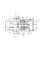
- FIG. 2 is a sectional view taken along line II-II of the rotary electric machine and the rack gear of FIG.
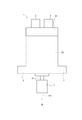
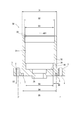
- FIG. 3 is a side view of the rotary electric machine of FIG.
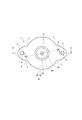
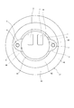
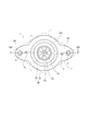
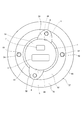
- FIG. 4 is a view of the rotary electric machine of FIG. 3 when viewed from the direction of arrow IV.
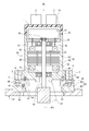
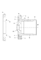
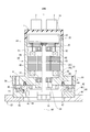
- FIG. 5 is a sectional view taken along line VV of the rotary electric machine of FIG.
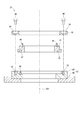
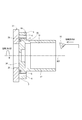
- FIG. 6 is a cross-sectional view of the rotary electric machine of FIG. 5 and the pallet on which it is set.
- FIG. 1 is a schematic view of the rotary electric machine and the rack gear of the first embodiment.
- FIG. 2 is a sectional view taken along line II-II of the rotary electric machine and the rack gear of FIG.
- FIG. 3 is a side view of the rotary electric machine of FIG.
- FIG. 4 is a view of the rotary electric machine of FIG. 3
- FIG. 7 is a cross-sectional view of the housing of FIG.
- FIG. 8 is an exploded view of the pallet of FIG.
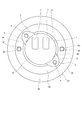
- FIG. 9 is a view of the rotary electric machine and the pallet of FIG. 6 as viewed from the direction of arrow IX.
- FIG. 10 is a view showing a first modification of the first embodiment, and is a plan view of a rotary electric machine and a pallet corresponding to FIG.
- FIG. 11 is a cross-sectional view showing the housing of the first embodiment and the chuck jig used in the cutting step of the inner diameter thereof.
- FIG. 12 is a cross-sectional view showing a state in which the housing of the first embodiment is set on the chuck jig.
- FIG. 13 is a side view of the rotary electric machine of the second modification of the first embodiment.
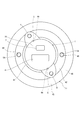
- FIG. 14 is a view of the rotary electric machine of FIG. 13 as viewed from the direction of arrow XIV.
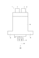
- FIG. 15 is a cross-sectional view taken along the line XV-XV of the rotary electric machine of FIG.
- FIG. 16 is a cross-sectional view of the rotary electric machine of FIG. 15 and the pallet on which it is set.
- FIG. 17 is a view of the rotary electric machine and the pallet of FIG. 16 as viewed from the direction of arrow XVII.
- FIG. 18 is a view showing a third modification of the first embodiment, and is a plan view of the rotary electric machine and the pallet corresponding to FIG.
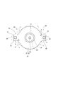
- FIG. 19 is a view of the rotary electric machine according to the second embodiment as viewed from the front side, and is a view corresponding to FIG. 4 of the first embodiment.
- the rotary electric machine 1 of the first embodiment is used for the purpose of transmitting power to the rack gear 50, for example, as a steering assist torque motor of an electric power steering device.
- the torque of the rotary electric machine 1 in the rack gear drive device 21 is a large diameter provided on a rack shaft (not shown) from a small diameter pulley 17 fixed to a shaft 63 included in the rotary electric machine 1 via a belt 16. It is transmitted to the pulley.
- the small-diameter pulley 17, belt 16, large-diameter pulley, rack gear 50, and the like described above are housed in the gear housing 11.
- the gear housing 11 has a rotary electric machine mounting portion 12.
- the housing 30 of the rotary electric machine 1 has a gear mounting portion 3.
- the gear mounting portion 3 corresponds to an “external mounting portion”.
- the rotary electric machine mounting portion 12 and the gear mounting portion 3 are fixed by bolts 13.
- the rotary electric machine 1 has a motor unit 80 on one side in the axial direction.
- the rotary electric machine 1 is configured as a mechatronics-integrated rotary electric machine in which an ECU (that is, a control unit) 10 is integrally provided on the other side in the axial direction.
- ECU that is, a control unit
- the output shaft side of the motor unit 80 shown on the lower side of FIG. 5 is referred to as the "front side”
- the cover 14 side shown on the upper side of FIG. 5 is referred to as the "rear side”.
- the motor unit 80 includes a housing 30, a stator 40, a rotor 60, and the like.
- the stator 40 is fixed to the stator accommodating portion 31 provided on the inner wall of the tubular portion 32 of the housing 30 by shrink fitting.
- the housing 30 has a bottomed tubular shape including a tubular portion 32 and a bottom portion 34.
- the housing 30 has an opening 33 on the rear side.
- the bottom portion 34 has an annular protrusion 24 concentric with the tubular portion 32.
- the annular protrusion 24 is radially inward with respect to the housing positioning hole 5 and projects to the side opposite to the tubular portion 32.
- the end portion of the tubular portion 32 on the bottom 34 side will be referred to as the bottom end portion 35.
- the front bearing 61 rotatably supports the shaft 63 on the front side in the axial direction.
- a gear mounting portion 3 is provided on the radial outer side of the tubular portion 32 on the front side.
- the housing 30 and the gear mounting portion 3 are integrally formed.
- the bottom portion 34 has a gear mounting portion 3.
- the gear mounting portion 3 projects radially outward from the tubular portion 32, and is formed at two positions facing each other.
- the gear mounting portion 3 has one gear mounting hole 4 for each.
- the gear mounting hole 4 is provided so as to penetrate in the axial direction.
- the gear mounting holes 4 are provided so as to face each other on a circumference concentric with the tubular portion 32.
- Two housing positioning holes 5 are provided in the bottom 34 of the housing 30 at positions facing each other 180 degrees. Further, the housing positioning hole 5 is provided by utilizing the gear mounting portion 3 protruding in the radial direction from the tubular portion 32 of the housing 30. The housing positioning holes 5 are provided at equal intervals on the circumference concentric with the tubular portion 32 of the housing 30. Further, the housing positioning hole 5 is located on the axial center of the tubular portion 32 (that is, the rotation axial center AX1 of the motor portion) with respect to the common tangent line L of the gear mounting portion 3 and the tubular portion 32 when the bottom portion 34 is viewed from the axial direction. Is located in.
- the chuck jig 51 for fixing the housing 30 of the cutting machine used in the cutting process of the housing 30 has two positioning pins 26. As shown in FIG. 12, the positioning pin 26 and the housing positioning hole 5 are fitted to position the housing 30 in the circumferential direction. The positioned housing 30 rotates in the rotation direction B, and the inner diameter is cut by the cutting tool 52 that operates in the cutting direction A.
- the pitch circle diameter D4 of the housing positioning hole 5 is larger than the inner diameter D3 of the stator accommodating portion 31 and the inner diameter D2 of the heat sink fixing portion 33. Further, the pitch circle diameter D4 is larger than the inner diameter D8 of the bottom end portion 35 and smaller than the outer diameter D1 of the bottom end portion 35.
- the difference between the pitch circle diameter D4 of the housing positioning hole 5 and the inner diameter D6 of the housing positioning hole 5 is larger than the inner diameter D3 of the stator housing portion 31.
- the sum of the pitch circle diameter D4 of the housing positioning hole 5, the inner diameter of the housing positioning hole 5, and D6 is smaller than the difference between the pitch circle diameter D5 of the gear mounting hole 4 and the inner diameter D7 of the gear mounting hole.
- the heat sink 20 is provided so as to face the rear end faces of the stator 40 and the rotor 60 at the opening 33 opposite to the bottom 34 of the housing 30.
- the rear bearing 62 rotatably supports the shaft 63 on the rear side in the axial direction.
- the heat sink 20 is fixed to the heat sink fixing portion 33 provided on the inner wall of the tubular portion 32 of the tubular housing 30 by shrink fitting at an arbitrary relative angle position around the axis of the tubular portion 32.
- the stator 40 is fixed to the stator accommodating portion 31 provided inside the tubular portion 32 by shrink fitting at an arbitrary relative angle position around the axis of the tubular portion 32.
- a winding 55 that forms a magnetic field by energization is wound around the stator 40.
- the rotor 60 is provided inside the stator 40 in the radial direction.
- the rotor 60 is rotatably provided on the inner side of the stator 40 via a gap.
- the rotor 60 has a plurality of permanent magnets (not shown) along the outer circumference, and rotates about the shaft 63 by a rotating magnetic field formed in the stator 40 by energizing the winding 55.
- the shaft 63 is fixed to the rotor 60 and rotates together with the rotor 60.
- the shaft 63 fixed to the center of the rotor 60 is rotatably supported by a front bearing 61 held by the bottom 34 of the housing 30 and a rear bearing 62 held by the heat sink 20.
- a small-diameter pulley 17 for transmitting rotation is provided at the front end of the shaft 63.
- a sensor magnet 68 for detecting the rotation angle is provided at the rear end of the shaft 63.
- the control unit 10 includes a substrate 15 fixed to the heat sink 20 and various electronic components mounted on the substrate 15. The heat generated by the electronic components by energization is released to the heat sink 20.
- the control unit 10 is provided on the side opposite to the stator 40 with respect to the heat sink 20, and controls the energization of the stator. Further, the control unit 10 has an external connection connector unit (hereinafter, connector unit) 2 and a cover 14.
- the cover 14 covers the rear opening 33 of the housing 30.
- a power supply cable or a signal cable from the outside is connected to the connector portion 2.
- the power supply terminal of the connector portion 2 is connected to the substrate 15 via a path (not shown).
- the relative angle of the connector portion 2 with respect to the housing 30 is a predetermined angle in consideration of the vehicle mounting space depending on the model.
- the rotary electric machine 1 is set on the pallet 27 as shown in FIG.
- the pallet 27 has a housing receiving portion 41, a holding portion 42, and a base portion 43.
- the base portion 43 includes an upper base portion 45 and a base portion lower 46.
- the pallet 27 is formed in the axial direction in the order of the base portion lower 46, the base portion upper 45, the housing receiving portion 41, and the holding portion 42 from the side opposite to the set rotary electric machine 1.
- a housing positioning pin 44 is provided on the upper surface of the housing receiving portion 41.
- Two housing positioning pins 44 are provided at positions facing each other by 180 degrees, and are fitted with the housing positioning holes 5.
- a pallet positioning hole 47 is provided on the lower surface of the housing receiving portion 41. 72 pallet positioning holes 47 are provided on the same circumference at regular intervals, that is, at 5 degree intervals.
- One pallet positioning pin 48 is provided on the base portion 45.
- the pallet positioning pin 48 is inserted into any one of the pallet positioning holes 47.
- the base portion 45 has two pallet fixing screw holes 53
- the pressing portion 42 has two pressing portion holes 54.
- the pallet fixing screw 49 penetrates the holding portion hole 54 and is screwed into the pallet fixing screw hole 53, and fixes the holding portion 42 and the base portion 43 while sandwiching the housing receiving portion 41.
- the position of the pallet positioning hole 47 can be changed relative to the base portion 43 by rotating the housing receiving portion 41 around the rotation axis AX1.
- the relative angle position of the pallet positioning hole 47 with respect to the base portion 45 is changed, the relative angle position of the housing positioning pin 44 with respect to the base portion 45 is also changed.
- a mechanism for changing the relative angular position of the housing positioning pin 44 with respect to the base portion 45 will be referred to as a rotation mechanism of the pallet 27.
- the rotary electric machine 1 Since the fixed positions of the stator 40 and the heat sink 20 around the axis can be changed, the rotary electric machine 1 has a structure in which the relative angle between the gear mounting portion 3 and the connector portion 2 around the axis has a degree of freedom. It has become.
- the relative angle between the gear mounting portion 3 and the connector portion 2 around the axis is changed with respect to the first embodiment shown in FIG.
- the relative angle position of the housing positioning pin 44 with respect to the base portion 45 is determined so as to correspond to the relative angle between the gear mounting portion 3 of the rotary electric machine 1 and the connector portion 2.
- the power transmission member is the joint 18.
- the gear mounting portion 56 has a shape that is longer in the radial direction than the gear mounting portion 3. That is, the shapes of the gear mounting portion 3 and the gear mounting portion 56 are different.
- the pitch circle diameter of the housing positioning hole 5 is the same.
- two housing positioning holes 5 are provided at positions facing each other by 180 degrees, as in the first embodiment.
- the external mounting portions 3 and 56 protruding from the tubular portion 32 may be chucked.
- a method of inserting a pin into the hole 4 for external mounting was used.
- the shapes, sizes, positions, etc. of the external mounting portions 3, 56 and the external mounting holes 4 differ depending on the model, there are variations in the relative angular position fixing jig in each assembling device when trying to support all models. It is inefficient because it takes a long time to set up.
- the housing positioning hole 5 is commonly adopted regardless of the model.
- the jigs 51 and 27 for fixing the housing 30 in the manufacturing process can be shared among the models.
- the housing 30 is tubular, the silhouette does not change even if it is rotated. Further, since the heat sink 20 and the stator 40 are fixed to the housing 30 at arbitrary relative angle positions, the relative angle between the gear mounting portion 3 and the connector portion 2 can be provided with a degree of freedom. Therefore, the degree of freedom in mounting the rotary electric machine 1 can be increased.
- the gear mounting portion 3 is provided with a plurality of housing positioning holes 5 at equal intervals on the circumference concentric with the tubular portion 32.
- the chuck jig 51 can be made common among the models by positioning the housing 30 in the rotation direction using the housing positioning hole 5.
- a pallet 27 capable of fixing the housing positioning pin 44 to the base portion 43 at an arbitrary relative angle is used, and the housing positioning hole 5 is fitted into the housing positioning pin 44 to rotate the housing 30.
- the pallet 27 can be shared among the models.
- the pallet 27 is flowed to each assembling facility to assemble and process each part. The housing 30 and each component are not rotated in each assembly facility.
- the pallet 27 By providing the rotating mechanism on the pallet 27 in this way, the assembling equipment does not require a rotating mechanism and power, so that the assembling equipment can be easily adjusted and inexpensive. Further, the pallet 27 needs to be operated to fix the relative angle of the housing 30 only at the start of the assembling process, and the pallet 27 itself does not require power for rotation. Therefore, the pallet 27 has a simple and inexpensive configuration. Can be.
- the rotary electric machine 1 of the present embodiment it is possible to change the relative angle between the gear mounting portion 3 and the connector portion 2 while suppressing the setup of the manufacturing equipment. Therefore, it is possible to provide the rotary electric machine 1 having a high degree of freedom of mounting and being easy to manufacture.
- the gear mounting portion 3 is a protrusion protruding in the radial direction of the housing 30.
- the housing positioning hole 5 is located on the axial side of the cylinder portion 32 with respect to the common tangent line L of the gear mounting portion 3 and the cylinder portion 32 when the bottom portion 34 is viewed from the axial direction. Therefore, it is not necessary to newly provide a protrusion protruding in the radial direction of the tubular portion 32 for the housing positioning hole 5. Therefore, the housing positioning hole 5 with high assembly accuracy with the pallet 27 can be obtained without expanding the silhouette of the housing 30.
- the housing positioning hole 5 is provided at the base of the gear mounting portion 3 and the housing positioning hole 5 is arranged on the outer side in the radial direction as compared with the form in which the housing positioning hole 5 is arranged near the center of the bottom portion 34. Assembling accuracy is high.
- the pitch circle diameter D4 of the housing positioning hole 5 is larger than the inner diameter D3 of the stator accommodating portion 31 and the inner diameter D2 of the heat sink fixing portion. Therefore, even if parts such as the stator 40 and the heat sink 20 are press-fitted from the opening 33 of the housing 30 when the housing positioning pin 44 is inserted into the housing positioning hole 5 for positioning, only the moment of force toward the center is obtained. Doesn't work. Therefore, the housing 30 is difficult to tilt.
- the housing positioning hole 5 by processing the housing positioning hole 5 to the outside in the radial direction from the inner diameter D8 of the bottom end portion 35, it is possible to prevent the bottom portion 34 from bending when the housing positioning hole 5 is processed. Therefore, the positioning accuracy of the housing positioning hole 5 is improved.
- the difference between the pitch circle diameter D4 of the housing positioning hole 5 and the inner diameter D6 of the housing positioning hole 5 is larger than the inner diameter D3 of the stator housing portion 31. Therefore, the positions of the stator 40 and the housing positioning pin 44 do not overlap in the radial direction. Therefore, since the stator 40 can be arranged on the front side as much as possible, the rotary electric machine 1 can be miniaturized.
- the pitch circle diameter D4 of the housing positioning hole 5 is smaller than the outer diameter D1 of the bottom end 35.
- the sum of the pitch circle diameter D4 of the housing positioning hole 5 and the inner diameter D6 of the housing positioning hole 5 is smaller than the difference between the pitch circle diameter D5 of the gear mounting hole 4 and the inner diameter D7 of the gear mounting hole 4. Therefore, the housing positioning hole 5 and the gear mounting hole 4 do not overlap with each other in the radial direction. Therefore, the housing positioning hole 5 can be arranged at an arbitrary position regardless of the position of the gear mounting hole 4.
- the bottom portion 34 has an annular protrusion 24 concentric with the tubular portion 32.
- the annular protrusion 24 is radially inward with respect to the housing positioning hole 5 and projects to the side opposite to the tubular portion 32. Therefore, the center positioning of the tubular portion 32 can be performed with high accuracy by using the annular protrusion 24.
- the gear mounting portion 57 of the rotary electric machine 28 has a two-sided width portion 65 composed of a pair of flat surfaces 29 parallel to the radial direction of the tubular portion 32.
- the width across flats 65 can be used as a chuck until the housing positioning hole 5 is machined. Further, by adopting the width across flats 65 in common regardless of the model of the rotary electric machine, it is possible to standardize the jig for fixing the housing 30 in the manufacturing process between the models.
- the number of housing positioning holes is not limited to two, and may be three or more.
- the housing positioning holes are provided at equal intervals on the circumference concentric with the housing cylinder, and the pitch circle diameter of the housing positioning holes and the positional relationship between the housing positioning holes are the same even between different products. It should be.
- the number of pallet positioning holes is not limited to 72 at 5 degree intervals.
- the pallet positioning holes may be arranged at regular intervals on the same circumference, and the number of holes may be arbitrarily determined.
- the number of pallet positioning pins provided on the base portion is not limited to one, and may be two or more.
- the configuration may be such that the rotation position of the pallet can be fixed corresponding to a plurality of pallet positioning holes on the same circumference of the lower surface of the housing receiving portion.
- the shape, size and position of the gear mounting holes may differ between models.
- the housing positioning hole may be a configuration that is commonly used regardless of the model of the rotary electric machine.
- the housing positioning hole may be provided entirely in the gear mounting portion or may be provided entirely out of the gear mounting portion.
- the housing positioning hole may be provided on the bottom portion by utilizing the gear mounting portion, and may be arranged on the outer side in the radial direction as compared with the form arranged near the center of the bottom portion.
- a width across flats may be formed in one of the plurality of external mounting portions.
Landscapes
- Engineering & Computer Science (AREA)
- Power Engineering (AREA)
- Microelectronics & Electronic Packaging (AREA)
- Motor Or Generator Frames (AREA)
Priority Applications (2)
| Application Number | Priority Date | Filing Date | Title |
|---|---|---|---|
| CN202080073432.9A CN114556751B (zh) | 2019-10-29 | 2020-10-16 | 旋转电机 |
| US17/660,811 US12040681B2 (en) | 2019-10-29 | 2022-04-26 | Rotary electric machine |
Applications Claiming Priority (2)
| Application Number | Priority Date | Filing Date | Title |
|---|---|---|---|
| JP2019-195785 | 2019-10-29 | ||
| JP2019195785A JP7160016B2 (ja) | 2019-10-29 | 2019-10-29 | 回転電機 |
Related Child Applications (1)
| Application Number | Title | Priority Date | Filing Date |
|---|---|---|---|
| US17/660,811 Continuation US12040681B2 (en) | 2019-10-29 | 2022-04-26 | Rotary electric machine |
Publications (1)
| Publication Number | Publication Date |
|---|---|
| WO2021085179A1 true WO2021085179A1 (ja) | 2021-05-06 |
Family
ID=75713795
Family Applications (1)
| Application Number | Title | Priority Date | Filing Date |
|---|---|---|---|
| PCT/JP2020/039083 Ceased WO2021085179A1 (ja) | 2019-10-29 | 2020-10-16 | 回転電機 |
Country Status (4)
| Country | Link |
|---|---|
| US (1) | US12040681B2 (enExample) |
| JP (1) | JP7160016B2 (enExample) |
| CN (1) | CN114556751B (enExample) |
| WO (1) | WO2021085179A1 (enExample) |
Families Citing this family (2)
| Publication number | Priority date | Publication date | Assignee | Title |
|---|---|---|---|---|
| CN113847392A (zh) * | 2021-09-14 | 2021-12-28 | 延锋国际座椅系统有限公司 | 一种汽车天窗调节机构 |
| CN119636887B (zh) * | 2025-02-19 | 2025-04-15 | 温州益能电器有限公司 | 一种基于磁齿轮技术的直驱线控转向盘 |
Citations (4)
| Publication number | Priority date | Publication date | Assignee | Title |
|---|---|---|---|---|
| JP2013128390A (ja) * | 2011-11-16 | 2013-06-27 | Nidec Techno Motor Corp | モールドモータ |
| JP2016186224A (ja) * | 2015-03-27 | 2016-10-27 | アスモ株式会社 | 液体ポンプ |
| JP2016214034A (ja) * | 2015-05-13 | 2016-12-15 | 株式会社デンソー | 回転電機及びその製造方法 |
| WO2019065339A1 (ja) * | 2017-09-29 | 2019-04-04 | 日本電産サーボ株式会社 | モータ |
Family Cites Families (11)
| Publication number | Priority date | Publication date | Assignee | Title |
|---|---|---|---|---|
| JP3279119B2 (ja) | 1995-03-16 | 2002-04-30 | 三菱自動車工業株式会社 | 異種ワーク対応型パレット |
| US6727613B2 (en) * | 2001-04-25 | 2004-04-27 | Asmo Co., Ltd. | Motor having rotatable shaft coupled with worm shaft |
| US8901800B2 (en) * | 2010-12-28 | 2014-12-02 | Asmo Co., Ltd. | Motor |
| JP5605250B2 (ja) | 2011-02-03 | 2014-10-15 | 富士通株式会社 | パレット装置 |
| JP6269282B2 (ja) | 2014-04-17 | 2018-01-31 | 日産自動車株式会社 | 筒状ケースの組立装置および組立方法 |
| JP2016136829A (ja) | 2015-01-14 | 2016-07-28 | 株式会社ジェイテクト | モータユニット |
| JP6421619B2 (ja) * | 2015-01-26 | 2018-11-14 | 株式会社デンソー | 回転電機 |
| JP6589656B2 (ja) * | 2016-01-21 | 2019-10-16 | 株式会社デンソー | モータ、および、これを用いた電動パワーステアリング装置 |
| US10113538B1 (en) * | 2016-06-17 | 2018-10-30 | The United States Of America As Represented By The Secretary Of The Navy | Impulse pump |
| CN109844448A (zh) * | 2016-10-19 | 2019-06-04 | 日本精工株式会社 | 传感器的组装构造体、电动马达、以及电动助力转向装置 |
| US10958131B2 (en) * | 2016-11-23 | 2021-03-23 | Nidec Corporation | Motor and electric power steering device |
-
2019
- 2019-10-29 JP JP2019195785A patent/JP7160016B2/ja active Active
-
2020
- 2020-10-16 CN CN202080073432.9A patent/CN114556751B/zh active Active
- 2020-10-16 WO PCT/JP2020/039083 patent/WO2021085179A1/ja not_active Ceased
-
2022
- 2022-04-26 US US17/660,811 patent/US12040681B2/en active Active
Patent Citations (4)
| Publication number | Priority date | Publication date | Assignee | Title |
|---|---|---|---|---|
| JP2013128390A (ja) * | 2011-11-16 | 2013-06-27 | Nidec Techno Motor Corp | モールドモータ |
| JP2016186224A (ja) * | 2015-03-27 | 2016-10-27 | アスモ株式会社 | 液体ポンプ |
| JP2016214034A (ja) * | 2015-05-13 | 2016-12-15 | 株式会社デンソー | 回転電機及びその製造方法 |
| WO2019065339A1 (ja) * | 2017-09-29 | 2019-04-04 | 日本電産サーボ株式会社 | モータ |
Also Published As
| Publication number | Publication date |
|---|---|
| US20220255398A1 (en) | 2022-08-11 |
| JP2021072647A (ja) | 2021-05-06 |
| US12040681B2 (en) | 2024-07-16 |
| CN114556751B (zh) | 2024-08-09 |
| JP7160016B2 (ja) | 2022-10-25 |
| CN114556751A (zh) | 2022-05-27 |
Similar Documents
| Publication | Publication Date | Title |
|---|---|---|
| US10494014B2 (en) | Motor including nonmagnetic contamination cover and electric power steering device including same | |
| US7235905B2 (en) | Electric power steering assembly | |
| US20080277189A1 (en) | Electric power steering apparatus | |
| CN209767318U (zh) | 电动致动器 | |
| US11496021B2 (en) | Electric motor having a rotor shaft and a first and a second bearing | |
| WO2021085179A1 (ja) | 回転電機 | |
| US20200251951A1 (en) | Electric actuator | |
| KR101905901B1 (ko) | 회전 장치 | |
| KR20170027337A (ko) | 다이렉트 드라이브 모터의 제조 방법, 및 지그 | |
| JP5868548B2 (ja) | ハイブリッド車両用回転電機のロータ保持構造 | |
| US7462967B2 (en) | Flat hollow brushless servo motor with tool mounting hole | |
| JP6850304B2 (ja) | 回転位置検出装置 | |
| JP2002364713A (ja) | モータ | |
| CN105449917A (zh) | 旋转电机 | |
| JP7380201B2 (ja) | 電動アクチュエータ | |
| JP2018161940A (ja) | 電動パワーステアリング装置 | |
| CN215596312U (zh) | 电动致动器 | |
| JP2007001364A (ja) | 電動パワーステアリング装置及び電動パワーステアリング装置のセンサ位置調整方法 | |
| JP2014217240A (ja) | モータ装置 | |
| JP7567465B2 (ja) | 電動アクチュエータの製造方法、および電動アクチュエータ | |
| JP2007006570A (ja) | ブラシレスモータ及びブラシレスモータのセンサ位置調整方法 | |
| JP7371491B2 (ja) | 電動アクチュエータ | |
| JP7434887B2 (ja) | 電動アクチュエータ | |
| JP7283305B2 (ja) | 電動アクチュエータ | |
| JP2007174789A (ja) | 位置調整機構付きモータ |
Legal Events
| Date | Code | Title | Description |
|---|---|---|---|
| 121 | Ep: the epo has been informed by wipo that ep was designated in this application |
Ref document number: 20880765 Country of ref document: EP Kind code of ref document: A1 |
|
| NENP | Non-entry into the national phase |
Ref country code: DE |
|
| 122 | Ep: pct application non-entry in european phase |
Ref document number: 20880765 Country of ref document: EP Kind code of ref document: A1 |