WO2021075334A1 - Échangeur de chaleur - Google Patents
Échangeur de chaleur Download PDFInfo
- Publication number
- WO2021075334A1 WO2021075334A1 PCT/JP2020/038071 JP2020038071W WO2021075334A1 WO 2021075334 A1 WO2021075334 A1 WO 2021075334A1 JP 2020038071 W JP2020038071 W JP 2020038071W WO 2021075334 A1 WO2021075334 A1 WO 2021075334A1
- Authority
- WO
- WIPO (PCT)
- Prior art keywords
- flow path
- header
- fin
- header flow
- plate
- Prior art date
Links
Images


Classifications
-
- F—MECHANICAL ENGINEERING; LIGHTING; HEATING; WEAPONS; BLASTING
- F28—HEAT EXCHANGE IN GENERAL
- F28D—HEAT-EXCHANGE APPARATUS, NOT PROVIDED FOR IN ANOTHER SUBCLASS, IN WHICH THE HEAT-EXCHANGE MEDIA DO NOT COME INTO DIRECT CONTACT
- F28D9/00—Heat-exchange apparatus having stationary plate-like or laminated conduit assemblies for both heat-exchange media, the media being in contact with different sides of a conduit wall
- F28D9/0031—Heat-exchange apparatus having stationary plate-like or laminated conduit assemblies for both heat-exchange media, the media being in contact with different sides of a conduit wall the conduits for one heat-exchange medium being formed by paired plates touching each other
- F28D9/0043—Heat-exchange apparatus having stationary plate-like or laminated conduit assemblies for both heat-exchange media, the media being in contact with different sides of a conduit wall the conduits for one heat-exchange medium being formed by paired plates touching each other the plates having openings therein for circulation of at least one heat-exchange medium from one conduit to another
- F28D9/005—Heat-exchange apparatus having stationary plate-like or laminated conduit assemblies for both heat-exchange media, the media being in contact with different sides of a conduit wall the conduits for one heat-exchange medium being formed by paired plates touching each other the plates having openings therein for circulation of at least one heat-exchange medium from one conduit to another the plates having openings therein for both heat-exchange media
-
- F—MECHANICAL ENGINEERING; LIGHTING; HEATING; WEAPONS; BLASTING
- F28—HEAT EXCHANGE IN GENERAL
- F28D—HEAT-EXCHANGE APPARATUS, NOT PROVIDED FOR IN ANOTHER SUBCLASS, IN WHICH THE HEAT-EXCHANGE MEDIA DO NOT COME INTO DIRECT CONTACT
- F28D1/00—Heat-exchange apparatus having stationary conduit assemblies for one heat-exchange medium only, the media being in contact with different sides of the conduit wall, in which the other heat-exchange medium is a large body of fluid, e.g. domestic or motor car radiators
- F28D1/02—Heat-exchange apparatus having stationary conduit assemblies for one heat-exchange medium only, the media being in contact with different sides of the conduit wall, in which the other heat-exchange medium is a large body of fluid, e.g. domestic or motor car radiators with heat-exchange conduits immersed in the body of fluid
- F28D1/03—Heat-exchange apparatus having stationary conduit assemblies for one heat-exchange medium only, the media being in contact with different sides of the conduit wall, in which the other heat-exchange medium is a large body of fluid, e.g. domestic or motor car radiators with heat-exchange conduits immersed in the body of fluid with plate-like or laminated conduits
- F28D1/0308—Heat-exchange apparatus having stationary conduit assemblies for one heat-exchange medium only, the media being in contact with different sides of the conduit wall, in which the other heat-exchange medium is a large body of fluid, e.g. domestic or motor car radiators with heat-exchange conduits immersed in the body of fluid with plate-like or laminated conduits the conduits being formed by paired plates touching each other
- F28D1/0325—Heat-exchange apparatus having stationary conduit assemblies for one heat-exchange medium only, the media being in contact with different sides of the conduit wall, in which the other heat-exchange medium is a large body of fluid, e.g. domestic or motor car radiators with heat-exchange conduits immersed in the body of fluid with plate-like or laminated conduits the conduits being formed by paired plates touching each other the plates having lateral openings therein for circulation of the heat-exchange medium from one conduit to another
- F28D1/0333—Heat-exchange apparatus having stationary conduit assemblies for one heat-exchange medium only, the media being in contact with different sides of the conduit wall, in which the other heat-exchange medium is a large body of fluid, e.g. domestic or motor car radiators with heat-exchange conduits immersed in the body of fluid with plate-like or laminated conduits the conduits being formed by paired plates touching each other the plates having lateral openings therein for circulation of the heat-exchange medium from one conduit to another the plates having integrated connecting members
-
- F—MECHANICAL ENGINEERING; LIGHTING; HEATING; WEAPONS; BLASTING
- F28—HEAT EXCHANGE IN GENERAL
- F28D—HEAT-EXCHANGE APPARATUS, NOT PROVIDED FOR IN ANOTHER SUBCLASS, IN WHICH THE HEAT-EXCHANGE MEDIA DO NOT COME INTO DIRECT CONTACT
- F28D9/00—Heat-exchange apparatus having stationary plate-like or laminated conduit assemblies for both heat-exchange media, the media being in contact with different sides of a conduit wall
- F28D9/0031—Heat-exchange apparatus having stationary plate-like or laminated conduit assemblies for both heat-exchange media, the media being in contact with different sides of a conduit wall the conduits for one heat-exchange medium being formed by paired plates touching each other
- F28D9/0043—Heat-exchange apparatus having stationary plate-like or laminated conduit assemblies for both heat-exchange media, the media being in contact with different sides of a conduit wall the conduits for one heat-exchange medium being formed by paired plates touching each other the plates having openings therein for circulation of at least one heat-exchange medium from one conduit to another
-
- F—MECHANICAL ENGINEERING; LIGHTING; HEATING; WEAPONS; BLASTING
- F28—HEAT EXCHANGE IN GENERAL
- F28F—DETAILS OF HEAT-EXCHANGE AND HEAT-TRANSFER APPARATUS, OF GENERAL APPLICATION
- F28F3/00—Plate-like or laminated elements; Assemblies of plate-like or laminated elements
- F28F3/02—Elements or assemblies thereof with means for increasing heat-transfer area, e.g. with fins, with recesses, with corrugations
- F28F3/04—Elements or assemblies thereof with means for increasing heat-transfer area, e.g. with fins, with recesses, with corrugations the means being integral with the element
- F28F3/048—Elements or assemblies thereof with means for increasing heat-transfer area, e.g. with fins, with recesses, with corrugations the means being integral with the element in the form of ribs integral with the element or local variations in thickness of the element, e.g. grooves, microchannels
-
- F—MECHANICAL ENGINEERING; LIGHTING; HEATING; WEAPONS; BLASTING
- F28—HEAT EXCHANGE IN GENERAL
- F28F—DETAILS OF HEAT-EXCHANGE AND HEAT-TRANSFER APPARATUS, OF GENERAL APPLICATION
- F28F3/00—Plate-like or laminated elements; Assemblies of plate-like or laminated elements
- F28F3/08—Elements constructed for building-up into stacks, e.g. capable of being taken apart for cleaning
- F28F3/086—Elements constructed for building-up into stacks, e.g. capable of being taken apart for cleaning having one or more openings therein forming tubular heat-exchange passages
-
- F—MECHANICAL ENGINEERING; LIGHTING; HEATING; WEAPONS; BLASTING
- F28—HEAT EXCHANGE IN GENERAL
- F28F—DETAILS OF HEAT-EXCHANGE AND HEAT-TRANSFER APPARATUS, OF GENERAL APPLICATION
- F28F3/00—Plate-like or laminated elements; Assemblies of plate-like or laminated elements
- F28F3/12—Elements constructed in the shape of a hollow panel, e.g. with channels
-
- F—MECHANICAL ENGINEERING; LIGHTING; HEATING; WEAPONS; BLASTING
- F28—HEAT EXCHANGE IN GENERAL
- F28F—DETAILS OF HEAT-EXCHANGE AND HEAT-TRANSFER APPARATUS, OF GENERAL APPLICATION
- F28F9/00—Casings; Header boxes; Auxiliary supports for elements; Auxiliary members within casings
- F28F9/02—Header boxes; End plates
- F28F9/0219—Arrangements for sealing end plates into casing or header box; Header box sub-elements
- F28F9/0221—Header boxes or end plates formed by stacked elements
-
- F—MECHANICAL ENGINEERING; LIGHTING; HEATING; WEAPONS; BLASTING
- F28—HEAT EXCHANGE IN GENERAL
- F28F—DETAILS OF HEAT-EXCHANGE AND HEAT-TRANSFER APPARATUS, OF GENERAL APPLICATION
- F28F9/00—Casings; Header boxes; Auxiliary supports for elements; Auxiliary members within casings
- F28F9/02—Header boxes; End plates
- F28F9/026—Header boxes; End plates with static flow control means, e.g. with means for uniformly distributing heat exchange media into conduits
- F28F9/027—Header boxes; End plates with static flow control means, e.g. with means for uniformly distributing heat exchange media into conduits in the form of distribution pipes
- F28F9/0273—Header boxes; End plates with static flow control means, e.g. with means for uniformly distributing heat exchange media into conduits in the form of distribution pipes with multiple holes
-
- F—MECHANICAL ENGINEERING; LIGHTING; HEATING; WEAPONS; BLASTING
- F28—HEAT EXCHANGE IN GENERAL
- F28F—DETAILS OF HEAT-EXCHANGE AND HEAT-TRANSFER APPARATUS, OF GENERAL APPLICATION
- F28F2225/00—Reinforcing means
- F28F2225/04—Reinforcing means for conduits
-
- F—MECHANICAL ENGINEERING; LIGHTING; HEATING; WEAPONS; BLASTING
- F28—HEAT EXCHANGE IN GENERAL
- F28F—DETAILS OF HEAT-EXCHANGE AND HEAT-TRANSFER APPARATUS, OF GENERAL APPLICATION
- F28F2240/00—Spacing means
-
- F—MECHANICAL ENGINEERING; LIGHTING; HEATING; WEAPONS; BLASTING
- F28—HEAT EXCHANGE IN GENERAL
- F28F—DETAILS OF HEAT-EXCHANGE AND HEAT-TRANSFER APPARATUS, OF GENERAL APPLICATION
- F28F2280/00—Mounting arrangements; Arrangements for facilitating assembling or disassembling of heat exchanger parts
- F28F2280/04—Means for preventing wrong assembling of parts
Definitions
- the plate fin laminate has a configuration in which the inner peripheral side of the header flow path is continuously joined in the stacking direction.
- the second fin member 20 is bent and continuous with the flat portion 20b having a flat surface and the flat surface of the flat portion 20b, and serves as an outer edge portion of the header opening 11a on the inner peripheral side of the header flow path 11. It has a peripheral support portion 20a and a peripheral support portion 20a.
- the inner peripheral support portion 20a of the second fin member 20 is joined to the first fin member 10 in another plate fin 2a adjacent in the stacking direction, and the inner peripheral side of the header flow path 11 in the plate fin laminated body 2 is in the stacking direction. It has a structure having a double wall surface extending to.
- FIG. 17 shows a plate composed of a first fin member 10 in contact with the lower second end plate 3b, and a second fin member 20 and a first fin member 10 laminated on the first fin member 10. It is an exploded perspective view which shows the fin 2a.
- FIG. 17 is a perspective view seen from below in the stacking direction.
- FIG. 18 shows a plate fin composed of a second fin member 20 in contact with the upper first end plate 3a, and a first fin member 10 and a second fin member 20 laminated under the second fin member 20. It is an exploded perspective view which shows 2a.
- FIG. 18 is a perspective view seen from above in the stacking direction.
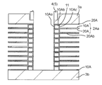
- FIG. 19 is a vertical cross-sectional view schematically showing a modified example of the configuration of the first embodiment.
- FIG. 19 shows the vicinity of the header flow path 11 in the first fin member 10A and the second fin member 20A.
- the recess forming the header flow path 11 in the first fin member 10A includes a header flow path top portion 10Ab formed in an annular shape and having a flat surface, and the header flow path top portion 10Ab on the inner peripheral side and the outer peripheral side. It is composed of a header flow path support portion (header flow path inner peripheral support portion 10Aa, header flow path outer peripheral support portion 10Ac) formed so as to support in the stacking direction on both sides.
- header flow path support portion header flow path inner peripheral support portion 10Aa, header flow path outer peripheral support portion 10Ac
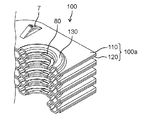
- the refrigerant of the supply pipe 4 flows separately in the state of the liquid phase and the gas phase
- the refrigerant of the liquid phase and the gas phase is supplied to the header flow path ports 80 at the upper and lower positions.
- a similar refrigerant with a balanced liquid phase and gas phase was supplied to the plate fin flow paths 13 of the laminated layers in the heat exchange region, and the plate fin laminated body 100 was generally balanced.
- the configuration is such that highly efficient heat exchange can be performed.
- Heat exchanger 2A 100 Plate fin laminate 2a, 2Aa, 100a Plate fin 3 End plate 3a 1st end plate 3b 2nd end plate 4 Feed pipe 5 Discharge pipe 6 Heat transfer cutoff slit 7 Interval regulation protrusion 8, 80 Header flow path port 8a 1st header flow path port 8b 2nd header flow path port 9 Positioning pin openings 10, 10A, 110 1st fin member 10a, 10Aa Header flow path inner peripheral support 10b, 10Ab Header flow path top 10c, 10Ac Header flow path Outer circumference support part 10d Protruding end on the inner circumference side 11,130 Header flow path 11a Header opening 12 Header communication flow path 13 Plate fin flow path 13a First plate fin flow path (straight) 13b 2nd plate fin flow path (arc-shaped) 16 Flow path transfer area 20, 20A, 120 Second fin member 20a Inner circumference support portion 20b, 20Ab Flat portion 21 Delivery flow path
Landscapes
- Engineering & Computer Science (AREA)
- Physics & Mathematics (AREA)
- Thermal Sciences (AREA)
- Mechanical Engineering (AREA)
- General Engineering & Computer Science (AREA)
- Heat-Exchange Devices With Radiators And Conduit Assemblies (AREA)
- Cooling Or The Like Of Semiconductors Or Solid State Devices (AREA)
Abstract
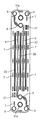
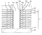
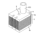
Selon la présente invention, dans un échangeur de chaleur dans lequel un deuxième fluide (B) est amené à s'écouler entre chaque couche dans un stratifié d'ailettes de plaque (2) et de la chaleur est échangée entre le deuxième fluide (B) et un premier fluide (A) s'écoulant à travers un trajet d'écoulement d'ailettes de plaque (13), les ailettes de plaque (2a) comprennent : une ouverture de collecteur (11a) dans laquelle le premier fluide est distribué depuis un tuyau de distribution ; des trajets d'écoulement de collecteur (11) formés autour de l'ouverture de collecteur (11a) ; une ouverture de trajet d'écoulement de collecteur (8) qui relie l'ouverture de collecteur (11a) et les trajets d'écoulement de collecteur (11) ; et un trajet d'écoulement d'ailettes de plaque (13) dans lequel le premier fluide provenant des trajets d'écoulement de collecteur (11) s'écoule et échange de la chaleur avec le deuxième fluide. Le côté de circonférence interne des trajets d'écoulement de collecteur (11) est assemblé en continu dans la direction de stratification dans le stratifié d'ailettes de plaque (2).
Priority Applications (2)
| Application Number | Priority Date | Filing Date | Title |
|---|---|---|---|
| EP20876390.4A EP4047298A4 (fr) | 2019-10-17 | 2020-10-08 | Échangeur de chaleur |
| CN202080015154.1A CN113424009B (zh) | 2019-10-17 | 2020-10-08 | 热交换器 |
Applications Claiming Priority (2)
| Application Number | Priority Date | Filing Date | Title |
|---|---|---|---|
| JP2019-190167 | 2019-10-17 | ||
| JP2019190167A JP7365634B2 (ja) | 2019-10-17 | 2019-10-17 | 熱交換器 |
Publications (1)
| Publication Number | Publication Date |
|---|---|
| WO2021075334A1 true WO2021075334A1 (fr) | 2021-04-22 |
Family
ID=75487118
Family Applications (1)
| Application Number | Title | Priority Date | Filing Date |
|---|---|---|---|
| PCT/JP2020/038071 WO2021075334A1 (fr) | 2019-10-17 | 2020-10-08 | Échangeur de chaleur |
Country Status (4)
| Country | Link |
|---|---|
| EP (1) | EP4047298A4 (fr) |
| JP (1) | JP7365634B2 (fr) |
| CN (1) | CN113424009B (fr) |
| WO (1) | WO2021075334A1 (fr) |
Families Citing this family (3)
| Publication number | Priority date | Publication date | Assignee | Title |
|---|---|---|---|---|
| US20230226590A1 (en) * | 2021-06-25 | 2023-07-20 | Foshan Huazhi Advanced Materials Co., Ltd. | Microchannel heat sink and method of manufacturing the same |
| KR102487015B1 (ko) * | 2021-12-28 | 2023-01-10 | 에너진(주) | 열절연부에 의해 열교환성을 향상시킨 인쇄기판형 열교환기 |
| KR102563976B1 (ko) * | 2022-11-30 | 2023-08-04 | 에너진(주) | 내구성을 향상시킨 인쇄기판형 열교환기, 이를 포함하는 수소저장장치, 및 수소압축장치 |
Citations (5)
| Publication number | Priority date | Publication date | Assignee | Title |
|---|---|---|---|---|
| JPH024367B2 (fr) | 1983-06-30 | 1990-01-29 | Gen Electric | |
| JP2001133184A (ja) * | 1999-11-01 | 2001-05-18 | Ebara Corp | プレート式熱交換器 |
| JP3965901B2 (ja) | 2000-10-27 | 2007-08-29 | 株式会社デンソー | 蒸発器 |
| JP3192719U (ja) | 2014-06-18 | 2014-08-28 | 有限会社和氣製作所 | 板状部材および熱交換器 |
| WO2019176567A1 (fr) * | 2018-03-15 | 2019-09-19 | 三菱電機株式会社 | Échangeur de chaleur à plaques et dispositif de pompe à chaleur l'intégrant |
Family Cites Families (12)
| Publication number | Priority date | Publication date | Assignee | Title |
|---|---|---|---|---|
| DE4313506A1 (de) * | 1993-04-24 | 1994-10-27 | Knecht Filterwerke Gmbh | Ölkühler in Scheibenbauweise |
| JP3864288B2 (ja) * | 1996-12-06 | 2006-12-27 | 昭和電工株式会社 | 積層型蒸発器 |
| JP4031668B2 (ja) * | 2002-05-23 | 2008-01-09 | 東京ラヂエーター製造株式会社 | 熱交換器 |
| US7568520B2 (en) * | 2005-06-21 | 2009-08-04 | Calsonic Kansei Corporation | Oil cooler |
| SE532344C2 (sv) * | 2007-12-21 | 2009-12-22 | Alfa Laval Corp Ab | Packningsstöd i värmeväxlare och värmeväxlare innefattande packningsstöd |
| US9250019B2 (en) * | 2009-07-27 | 2016-02-02 | Korea Delphi Automotive Systems Corporation | Plate heat exchanger |
| JP6001170B2 (ja) * | 2012-06-26 | 2016-10-05 | エーバーシュペッヒャー・エグゾースト・テクノロジー・ゲーエムベーハー・ウント・コンパニー・カーゲー | 蒸発器、内燃機関用廃熱利用装置、及び内燃機関 |
| ES2725228T3 (es) | 2012-11-07 | 2019-09-20 | Alfa Laval Corp Ab | Paquete de placas y método de fabricación de un paquete de placas |
| JP6504367B2 (ja) * | 2016-03-28 | 2019-04-24 | パナソニックIpマネジメント株式会社 | 熱交換器 |
| JP6906130B2 (ja) * | 2016-10-21 | 2021-07-21 | パナソニックIpマネジメント株式会社 | 熱交換器およびそれを用いた冷凍システム |
| JP2019100563A (ja) * | 2017-11-29 | 2019-06-24 | パナソニックIpマネジメント株式会社 | 熱交換器およびそれを用いた冷凍システム |
| JP2019100565A (ja) * | 2017-11-29 | 2019-06-24 | パナソニックIpマネジメント株式会社 | 熱交換器及びそれを用いた冷凍システム |
-
2019
- 2019-10-17 JP JP2019190167A patent/JP7365634B2/ja active Active
-
2020
- 2020-10-08 CN CN202080015154.1A patent/CN113424009B/zh active Active
- 2020-10-08 EP EP20876390.4A patent/EP4047298A4/fr active Pending
- 2020-10-08 WO PCT/JP2020/038071 patent/WO2021075334A1/fr unknown
Patent Citations (5)
| Publication number | Priority date | Publication date | Assignee | Title |
|---|---|---|---|---|
| JPH024367B2 (fr) | 1983-06-30 | 1990-01-29 | Gen Electric | |
| JP2001133184A (ja) * | 1999-11-01 | 2001-05-18 | Ebara Corp | プレート式熱交換器 |
| JP3965901B2 (ja) | 2000-10-27 | 2007-08-29 | 株式会社デンソー | 蒸発器 |
| JP3192719U (ja) | 2014-06-18 | 2014-08-28 | 有限会社和氣製作所 | 板状部材および熱交換器 |
| WO2019176567A1 (fr) * | 2018-03-15 | 2019-09-19 | 三菱電機株式会社 | Échangeur de chaleur à plaques et dispositif de pompe à chaleur l'intégrant |
Also Published As
| Publication number | Publication date |
|---|---|
| CN113424009B (zh) | 2022-12-20 |
| CN113424009A (zh) | 2021-09-21 |
| EP4047298A1 (fr) | 2022-08-24 |
| EP4047298A4 (fr) | 2022-11-23 |
| JP7365634B2 (ja) | 2023-10-20 |
| JP2021063637A (ja) | 2021-04-22 |
Similar Documents
| Publication | Publication Date | Title |
|---|---|---|
| WO2021075334A1 (fr) | Échangeur de chaleur | |
| JP6504367B2 (ja) | 熱交換器 | |
| US6959492B1 (en) | Plate type heat exchanger and method of manufacturing the heat exchanger | |
| JP6528283B2 (ja) | 熱交換器 | |
| EP3150952A1 (fr) | Plaque de transfert de chaleur et échangeur de chaleur à plaques | |
| JP5892453B2 (ja) | 熱交換器 | |
| TW200538695A (en) | Heat exchanger and method of producing the same | |
| JP2017072331A (ja) | 熱交換器およびその製造方法 | |
| US20070235174A1 (en) | Heat exchanger | |
| WO2021075336A1 (fr) | Échangeur de chaleur | |
| JP2003021486A (ja) | 熱交換器 | |
| JP4482997B2 (ja) | 積層式熱交換器およびその製造方法 | |
| KR102634169B1 (ko) | 적층 플레이트형 열교환기 | |
| JP2020531777A (ja) | 伝熱プレートおよび熱交換器 | |
| JP2005083623A (ja) | 熱交換ユニット及び積層型熱交換器 | |
| CN216954157U (zh) | 一种铝制钎焊板式换热器 | |
| CN116242174B (zh) | 一种微通道换热器及其运行方法 | |
| JP2005207725A (ja) | 熱交換器 | |
| WO2022059437A1 (fr) | Échangeur de chaleur | |
| JP2000249486A (ja) | 積層式熱交換器およびその製造方法 | |
| JPH11218395A (ja) | 積層式熱交換器の製造方法 | |
| CN115540643A (zh) | 工作流体通道片及具有其的换热器 | |
| JP2020531776A (ja) | 熱交換器 | |
| JP2000329490A (ja) | 積層型熱交換器 | |
| JPH058267U (ja) | 積層板型熱交換器 |
Legal Events
| Date | Code | Title | Description |
|---|---|---|---|
| 121 | Ep: the epo has been informed by wipo that ep was designated in this application |
Ref document number: 20876390 Country of ref document: EP Kind code of ref document: A1 |
|
| NENP | Non-entry into the national phase |
Ref country code: DE |
|
| ENP | Entry into the national phase |
Ref document number: 2020876390 Country of ref document: EP Effective date: 20220517 |