WO2021075334A1 - Heat exchanger - Google Patents
Heat exchanger Download PDFInfo
- Publication number
- WO2021075334A1 WO2021075334A1 PCT/JP2020/038071 JP2020038071W WO2021075334A1 WO 2021075334 A1 WO2021075334 A1 WO 2021075334A1 JP 2020038071 W JP2020038071 W JP 2020038071W WO 2021075334 A1 WO2021075334 A1 WO 2021075334A1
- Authority
- WO
- WIPO (PCT)
- Prior art keywords
- flow path
- header
- fin
- header flow
- plate
- Prior art date
Links
Images


Classifications
-
- F—MECHANICAL ENGINEERING; LIGHTING; HEATING; WEAPONS; BLASTING
- F28—HEAT EXCHANGE IN GENERAL
- F28D—HEAT-EXCHANGE APPARATUS, NOT PROVIDED FOR IN ANOTHER SUBCLASS, IN WHICH THE HEAT-EXCHANGE MEDIA DO NOT COME INTO DIRECT CONTACT
- F28D9/00—Heat-exchange apparatus having stationary plate-like or laminated conduit assemblies for both heat-exchange media, the media being in contact with different sides of a conduit wall
- F28D9/0031—Heat-exchange apparatus having stationary plate-like or laminated conduit assemblies for both heat-exchange media, the media being in contact with different sides of a conduit wall the conduits for one heat-exchange medium being formed by paired plates touching each other
- F28D9/0043—Heat-exchange apparatus having stationary plate-like or laminated conduit assemblies for both heat-exchange media, the media being in contact with different sides of a conduit wall the conduits for one heat-exchange medium being formed by paired plates touching each other the plates having openings therein for circulation of at least one heat-exchange medium from one conduit to another
- F28D9/005—Heat-exchange apparatus having stationary plate-like or laminated conduit assemblies for both heat-exchange media, the media being in contact with different sides of a conduit wall the conduits for one heat-exchange medium being formed by paired plates touching each other the plates having openings therein for circulation of at least one heat-exchange medium from one conduit to another the plates having openings therein for both heat-exchange media
-
- F—MECHANICAL ENGINEERING; LIGHTING; HEATING; WEAPONS; BLASTING
- F28—HEAT EXCHANGE IN GENERAL
- F28D—HEAT-EXCHANGE APPARATUS, NOT PROVIDED FOR IN ANOTHER SUBCLASS, IN WHICH THE HEAT-EXCHANGE MEDIA DO NOT COME INTO DIRECT CONTACT
- F28D1/00—Heat-exchange apparatus having stationary conduit assemblies for one heat-exchange medium only, the media being in contact with different sides of the conduit wall, in which the other heat-exchange medium is a large body of fluid, e.g. domestic or motor car radiators
- F28D1/02—Heat-exchange apparatus having stationary conduit assemblies for one heat-exchange medium only, the media being in contact with different sides of the conduit wall, in which the other heat-exchange medium is a large body of fluid, e.g. domestic or motor car radiators with heat-exchange conduits immersed in the body of fluid
- F28D1/03—Heat-exchange apparatus having stationary conduit assemblies for one heat-exchange medium only, the media being in contact with different sides of the conduit wall, in which the other heat-exchange medium is a large body of fluid, e.g. domestic or motor car radiators with heat-exchange conduits immersed in the body of fluid with plate-like or laminated conduits
- F28D1/0308—Heat-exchange apparatus having stationary conduit assemblies for one heat-exchange medium only, the media being in contact with different sides of the conduit wall, in which the other heat-exchange medium is a large body of fluid, e.g. domestic or motor car radiators with heat-exchange conduits immersed in the body of fluid with plate-like or laminated conduits the conduits being formed by paired plates touching each other
- F28D1/0325—Heat-exchange apparatus having stationary conduit assemblies for one heat-exchange medium only, the media being in contact with different sides of the conduit wall, in which the other heat-exchange medium is a large body of fluid, e.g. domestic or motor car radiators with heat-exchange conduits immersed in the body of fluid with plate-like or laminated conduits the conduits being formed by paired plates touching each other the plates having lateral openings therein for circulation of the heat-exchange medium from one conduit to another
- F28D1/0333—Heat-exchange apparatus having stationary conduit assemblies for one heat-exchange medium only, the media being in contact with different sides of the conduit wall, in which the other heat-exchange medium is a large body of fluid, e.g. domestic or motor car radiators with heat-exchange conduits immersed in the body of fluid with plate-like or laminated conduits the conduits being formed by paired plates touching each other the plates having lateral openings therein for circulation of the heat-exchange medium from one conduit to another the plates having integrated connecting members
-
- F—MECHANICAL ENGINEERING; LIGHTING; HEATING; WEAPONS; BLASTING
- F28—HEAT EXCHANGE IN GENERAL
- F28D—HEAT-EXCHANGE APPARATUS, NOT PROVIDED FOR IN ANOTHER SUBCLASS, IN WHICH THE HEAT-EXCHANGE MEDIA DO NOT COME INTO DIRECT CONTACT
- F28D9/00—Heat-exchange apparatus having stationary plate-like or laminated conduit assemblies for both heat-exchange media, the media being in contact with different sides of a conduit wall
- F28D9/0031—Heat-exchange apparatus having stationary plate-like or laminated conduit assemblies for both heat-exchange media, the media being in contact with different sides of a conduit wall the conduits for one heat-exchange medium being formed by paired plates touching each other
- F28D9/0043—Heat-exchange apparatus having stationary plate-like or laminated conduit assemblies for both heat-exchange media, the media being in contact with different sides of a conduit wall the conduits for one heat-exchange medium being formed by paired plates touching each other the plates having openings therein for circulation of at least one heat-exchange medium from one conduit to another
-
- F—MECHANICAL ENGINEERING; LIGHTING; HEATING; WEAPONS; BLASTING
- F28—HEAT EXCHANGE IN GENERAL
- F28F—DETAILS OF HEAT-EXCHANGE AND HEAT-TRANSFER APPARATUS, OF GENERAL APPLICATION
- F28F3/00—Plate-like or laminated elements; Assemblies of plate-like or laminated elements
- F28F3/02—Elements or assemblies thereof with means for increasing heat-transfer area, e.g. with fins, with recesses, with corrugations
- F28F3/04—Elements or assemblies thereof with means for increasing heat-transfer area, e.g. with fins, with recesses, with corrugations the means being integral with the element
- F28F3/048—Elements or assemblies thereof with means for increasing heat-transfer area, e.g. with fins, with recesses, with corrugations the means being integral with the element in the form of ribs integral with the element or local variations in thickness of the element, e.g. grooves, microchannels
-
- F—MECHANICAL ENGINEERING; LIGHTING; HEATING; WEAPONS; BLASTING
- F28—HEAT EXCHANGE IN GENERAL
- F28F—DETAILS OF HEAT-EXCHANGE AND HEAT-TRANSFER APPARATUS, OF GENERAL APPLICATION
- F28F3/00—Plate-like or laminated elements; Assemblies of plate-like or laminated elements
- F28F3/08—Elements constructed for building-up into stacks, e.g. capable of being taken apart for cleaning
- F28F3/086—Elements constructed for building-up into stacks, e.g. capable of being taken apart for cleaning having one or more openings therein forming tubular heat-exchange passages
-
- F—MECHANICAL ENGINEERING; LIGHTING; HEATING; WEAPONS; BLASTING
- F28—HEAT EXCHANGE IN GENERAL
- F28F—DETAILS OF HEAT-EXCHANGE AND HEAT-TRANSFER APPARATUS, OF GENERAL APPLICATION
- F28F3/00—Plate-like or laminated elements; Assemblies of plate-like or laminated elements
- F28F3/12—Elements constructed in the shape of a hollow panel, e.g. with channels
-
- F—MECHANICAL ENGINEERING; LIGHTING; HEATING; WEAPONS; BLASTING
- F28—HEAT EXCHANGE IN GENERAL
- F28F—DETAILS OF HEAT-EXCHANGE AND HEAT-TRANSFER APPARATUS, OF GENERAL APPLICATION
- F28F9/00—Casings; Header boxes; Auxiliary supports for elements; Auxiliary members within casings
- F28F9/02—Header boxes; End plates
- F28F9/0219—Arrangements for sealing end plates into casing or header box; Header box sub-elements
- F28F9/0221—Header boxes or end plates formed by stacked elements
-
- F—MECHANICAL ENGINEERING; LIGHTING; HEATING; WEAPONS; BLASTING
- F28—HEAT EXCHANGE IN GENERAL
- F28F—DETAILS OF HEAT-EXCHANGE AND HEAT-TRANSFER APPARATUS, OF GENERAL APPLICATION
- F28F9/00—Casings; Header boxes; Auxiliary supports for elements; Auxiliary members within casings
- F28F9/02—Header boxes; End plates
- F28F9/026—Header boxes; End plates with static flow control means, e.g. with means for uniformly distributing heat exchange media into conduits
- F28F9/027—Header boxes; End plates with static flow control means, e.g. with means for uniformly distributing heat exchange media into conduits in the form of distribution pipes
- F28F9/0273—Header boxes; End plates with static flow control means, e.g. with means for uniformly distributing heat exchange media into conduits in the form of distribution pipes with multiple holes
-
- F—MECHANICAL ENGINEERING; LIGHTING; HEATING; WEAPONS; BLASTING
- F28—HEAT EXCHANGE IN GENERAL
- F28F—DETAILS OF HEAT-EXCHANGE AND HEAT-TRANSFER APPARATUS, OF GENERAL APPLICATION
- F28F2225/00—Reinforcing means
- F28F2225/04—Reinforcing means for conduits
-
- F—MECHANICAL ENGINEERING; LIGHTING; HEATING; WEAPONS; BLASTING
- F28—HEAT EXCHANGE IN GENERAL
- F28F—DETAILS OF HEAT-EXCHANGE AND HEAT-TRANSFER APPARATUS, OF GENERAL APPLICATION
- F28F2240/00—Spacing means
-
- F—MECHANICAL ENGINEERING; LIGHTING; HEATING; WEAPONS; BLASTING
- F28—HEAT EXCHANGE IN GENERAL
- F28F—DETAILS OF HEAT-EXCHANGE AND HEAT-TRANSFER APPARATUS, OF GENERAL APPLICATION
- F28F2280/00—Mounting arrangements; Arrangements for facilitating assembling or disassembling of heat exchanger parts
- F28F2280/04—Means for preventing wrong assembling of parts
Definitions
- the plate fin laminate has a configuration in which the inner peripheral side of the header flow path is continuously joined in the stacking direction.
- the second fin member 20 is bent and continuous with the flat portion 20b having a flat surface and the flat surface of the flat portion 20b, and serves as an outer edge portion of the header opening 11a on the inner peripheral side of the header flow path 11. It has a peripheral support portion 20a and a peripheral support portion 20a.
- the inner peripheral support portion 20a of the second fin member 20 is joined to the first fin member 10 in another plate fin 2a adjacent in the stacking direction, and the inner peripheral side of the header flow path 11 in the plate fin laminated body 2 is in the stacking direction. It has a structure having a double wall surface extending to.
- FIG. 17 shows a plate composed of a first fin member 10 in contact with the lower second end plate 3b, and a second fin member 20 and a first fin member 10 laminated on the first fin member 10. It is an exploded perspective view which shows the fin 2a.
- FIG. 17 is a perspective view seen from below in the stacking direction.
- FIG. 18 shows a plate fin composed of a second fin member 20 in contact with the upper first end plate 3a, and a first fin member 10 and a second fin member 20 laminated under the second fin member 20. It is an exploded perspective view which shows 2a.
- FIG. 18 is a perspective view seen from above in the stacking direction.
- FIG. 19 is a vertical cross-sectional view schematically showing a modified example of the configuration of the first embodiment.
- FIG. 19 shows the vicinity of the header flow path 11 in the first fin member 10A and the second fin member 20A.
- the recess forming the header flow path 11 in the first fin member 10A includes a header flow path top portion 10Ab formed in an annular shape and having a flat surface, and the header flow path top portion 10Ab on the inner peripheral side and the outer peripheral side. It is composed of a header flow path support portion (header flow path inner peripheral support portion 10Aa, header flow path outer peripheral support portion 10Ac) formed so as to support in the stacking direction on both sides.
- header flow path support portion header flow path inner peripheral support portion 10Aa, header flow path outer peripheral support portion 10Ac
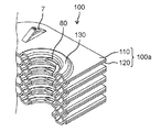
- the refrigerant of the supply pipe 4 flows separately in the state of the liquid phase and the gas phase
- the refrigerant of the liquid phase and the gas phase is supplied to the header flow path ports 80 at the upper and lower positions.
- a similar refrigerant with a balanced liquid phase and gas phase was supplied to the plate fin flow paths 13 of the laminated layers in the heat exchange region, and the plate fin laminated body 100 was generally balanced.
- the configuration is such that highly efficient heat exchange can be performed.
- Heat exchanger 2A 100 Plate fin laminate 2a, 2Aa, 100a Plate fin 3 End plate 3a 1st end plate 3b 2nd end plate 4 Feed pipe 5 Discharge pipe 6 Heat transfer cutoff slit 7 Interval regulation protrusion 8, 80 Header flow path port 8a 1st header flow path port 8b 2nd header flow path port 9 Positioning pin openings 10, 10A, 110 1st fin member 10a, 10Aa Header flow path inner peripheral support 10b, 10Ab Header flow path top 10c, 10Ac Header flow path Outer circumference support part 10d Protruding end on the inner circumference side 11,130 Header flow path 11a Header opening 12 Header communication flow path 13 Plate fin flow path 13a First plate fin flow path (straight) 13b 2nd plate fin flow path (arc-shaped) 16 Flow path transfer area 20, 20A, 120 Second fin member 20a Inner circumference support portion 20b, 20Ab Flat portion 21 Delivery flow path
Abstract
In a heat exchanger in which a second fluid (B) is caused to flow between each layer in a plate fin laminate (2) and heat is exchanged between the second fluid (B) and a first fluid (A) flowing through a plate fin flow path (13), the plate fins (2a) include: a header opening (11a) into which the first fluid is supplied from a supply pipe; header flow paths (11) formed around the header opening (11a); a header flow path opening (8) that connects the header opening (11a) and the header flow paths (11); and a plate fin flow path (13) into which the first fluid from the header flow paths (11) flows and exchanges heat with the second fluid. The internal circumference side of the header flow paths (11) are continuously joined in the lamination direction of in the plate fin laminate (2).
Description
本開示は、熱交換器に関し、特に、冷媒が流れる板状のプレートフィンを積層して構成された積層型プレートフィンの熱交換器に関する。
The present disclosure relates to a heat exchanger, and more particularly to a heat exchanger of a laminated plate fin configured by laminating plate-shaped plate fins through which a refrigerant flows.
異なる熱エネルギーを有する流体間において、熱エネルギーを交換するために使用される熱交換器は、多くの機器に用いられている。特に積層型プレートフィンの熱交換器は、例えば、家庭用および車両用の空気調和機、コンピュータ、および各種電気機器などにおいて広く用いられている。
Heat exchangers used to exchange thermal energy between fluids with different thermal energies are used in many devices. In particular, heat exchangers of laminated plate fins are widely used in, for example, air conditioners for homes and vehicles, computers, and various electric devices.
積層型プレートフィンの熱交換器は、板状のプレートフィンの中に形成された流路を流れる流体(冷媒)と、積層されたプレートフィンの間を流れる流体(空気)との間で熱交換を行う形式である。
The heat exchanger of the laminated plate fins exchanges heat between the fluid (refrigerant) flowing through the flow path formed in the plate-shaped plate fins and the fluid (air) flowing between the laminated plate fins. It is a form to do.
上記のような積層型プレートフィンの熱交換器の分野においては、軽量化、小型化および熱交換の効率化を目的として各種の構成が提案されている(例えば、特許文献1および特許文献2参照)。
In the field of heat exchangers for laminated plate fins as described above, various configurations have been proposed for the purpose of weight reduction, miniaturization, and efficiency of heat exchange (see, for example, Patent Document 1 and Patent Document 2). ).
積層型プレートフィンの熱交換器の分野においては、軽量化、小型化および熱交換の効率化を目的として、プレートフィンを熱伝導率の高い材料で厚みを薄く構成し、プレートフィンに設けられた流路に従来の熱交換器に比べて高い圧力の流体(冷媒)を流すことが検討されている。
In the field of heat exchangers for laminated plate fins, the plate fins are made of a material having high thermal conductivity to reduce the thickness for the purpose of weight reduction, miniaturization, and efficiency of heat exchange, and are provided on the plate fins. It is being studied to flow a fluid (hydrogen) having a higher pressure than a conventional heat exchanger in the flow path.
積層型プレートフィンの熱交換器において、プレートフィンに設けられた流路に対して高圧の冷媒を流す構成では、流路が変形して、冷媒の流量と流速にバラツキが生じ、熱交換器としての性能が低下するおそれがあった。このような複数のプレートフィンを積層して構成された熱交換器においては、流路に冷媒が流れることによる積層方向への変形、歪みを防止するために積層方向の両端側には、剛性が高く、厚みのある金属部材が端板として設けられていた(特許文献3参照)。このような端板は、積層されたプレートフィンと共にロウ付けにより接合される構成である。しかしながら、このような端板は、接合されるプレートフィンと熱容量が大きく異なり、また部材強度の違いからロウ付け不良が発生しやすいという問題を有していた。このため、上記のように構成された従来の積層型プレートフィンの熱交換器は、軽量化および小型化において課題を有すると共に、供給される冷媒に対する耐圧性および信頼性においても課題を有する構成であった。
In the heat exchanger of the laminated plate fin, in the configuration in which the high-pressure refrigerant flows through the flow path provided in the plate fin, the flow path is deformed and the flow rate and the flow velocity of the refrigerant vary, so that the heat exchanger can be used as a heat exchanger. There was a risk that the performance of the In a heat exchanger configured by stacking a plurality of such plate fins, rigidity is provided on both ends in the stacking direction in order to prevent deformation and distortion in the stacking direction due to the flow of refrigerant in the flow path. A tall and thick metal member was provided as an end plate (see Patent Document 3). Such end plates are brazed together with laminated plate fins. However, such an end plate has a problem that the heat capacity is significantly different from that of the plate fins to be joined, and brazing defects are likely to occur due to the difference in member strength. Therefore, the conventional heat exchanger of the laminated plate fin configured as described above has problems in weight reduction and miniaturization, and also has problems in pressure resistance and reliability with respect to the supplied refrigerant. there were.
本開示は、軽量化、小型化および熱交換の効率化を達成すると共に、熱交換器としての耐圧性を確保することができる構成を有して、高圧の冷媒を流路に流すことが可能な信頼性が高い熱交換器を提供することを目的とする。
The present disclosure has a configuration capable of achieving weight reduction, miniaturization, and efficiency of heat exchange, and ensuring pressure resistance as a heat exchanger, so that a high-pressure refrigerant can flow through a flow path. The purpose is to provide a highly reliable heat exchanger.
本開示の一態様の熱交換器は、
第1流体が流れる流路を有するプレートフィンが積層されたプレートフィン積層体と、
プレートフィン積層体における各層のプレートフィンの流路に流れる第1流体の給入または排出を行う給排管と、を備え、
プレートフィン積層体の各層間の隙間に第2流体を流して、プレートフィンの流路を流れる第1流体と第2流体との間で熱交換を行う熱交換器であって、
プレートフィンは、
給排管が給入管として機能するとき、給入管からの第1流体が給入されるヘッダ開口と、
ヘッダ開口の周りに形成されるヘッダ流路と、
ヘッダ流路からの第1流体が流れて、第2流体との間で熱交換を行うプレートフィン流路と、を含み、
プレートフィン積層体において、ヘッダ流路の内周側が積層方向に連続して接合された構成を有する。 The heat exchanger of one aspect of the present disclosure is
A plate fin laminate in which plate fins having a flow path through which the first fluid flows are laminated, and
A supply / discharge pipe for supplying or discharging a first fluid flowing through the flow path of the plate fins of each layer in the plate fin laminate is provided.
A heat exchanger in which a second fluid is passed through the gaps between the layers of the plate fin laminate to exchange heat between the first fluid and the second fluid flowing through the flow path of the plate fins.
Plate fins
When the supply / discharge pipe functions as a supply / discharge pipe, a header opening into which the first fluid from the supply / discharge pipe is supplied and
The header flow path formed around the header opening,
Includes a plate fin flow path through which the first fluid flows from the header flow path and exchanges heat with the second fluid.
The plate fin laminate has a configuration in which the inner peripheral side of the header flow path is continuously joined in the stacking direction.
本開示に係る一態様の熱交換器は、
第1流体が流れる流路を有するプレートフィンが積層されたプレートフィン積層体と、
プレートフィン積層体における各層のプレートフィンの流路に流れる第1流体の給入または排出を行う給排管と、を備え、
プレートフィン積層体の各層間の隙間に第2流体を流して、プレートフィンの流路を流れる第1流体と第2流体との間で熱交換を行う熱交換器であって、
プレートフィンは、
給排管が給入管として機能するとき、給入管からの第1流体が給入されるヘッダ開口と、
ヘッダ開口の周りに形成されるヘッダ流路と、
ヘッダ流路からの第1流体が流れて、第2流体との間で熱交換を行うプレートフィン流路と、を含み、
プレートフィン積層体において、ヘッダ流路の内周側が積層方向に連続して接合された構成を有する。 The heat exchanger of one aspect according to the present disclosure is
A plate fin laminate in which plate fins having a flow path through which the first fluid flows are laminated, and
A supply / discharge pipe for supplying or discharging a first fluid flowing through the flow path of the plate fins of each layer in the plate fin laminate is provided.
A heat exchanger in which a second fluid is passed through the gaps between the layers of the plate fin laminate to exchange heat between the first fluid and the second fluid flowing through the flow path of the plate fins.
Plate fins
When the supply / discharge pipe functions as a supply / discharge pipe, a header opening into which the first fluid from the supply / discharge pipe is supplied and
The header flow path formed around the header opening,
Includes a plate fin flow path through which the first fluid flows from the header flow path and exchanges heat with the second fluid.
The plate fin laminate has a configuration in which the inner peripheral side of the header flow path is continuously joined in the stacking direction.
なお、ヘッダ流路の外周側が積層方向に連続して接合された構成としてもよい。
Note that the outer peripheral side of the header flow path may be continuously joined in the stacking direction.
なお、ヘッダ流路の内周側が積層方向に連続する壁面により構成されてもよい。
The inner peripheral side of the header flow path may be composed of a wall surface continuous in the stacking direction.
なお、プレートフィン積層体において、ヘッダ流路の内周側が2重構造の壁面により構成されてもよい。
In the plate fin laminated body, the inner peripheral side of the header flow path may be composed of a wall surface having a double structure.
なお、プレートフィンにおいて、ヘッダ開口とヘッダ流路とを連通するヘッダ流路口が、ヘッダ流路の内周側に配設されてもよい。
In the plate fin, the header flow path port that communicates the header opening and the header flow path may be arranged on the inner peripheral side of the header flow path.
なお、プレートフィンが、ヘッダ開口とヘッダ流路とを連通するヘッダ流路口を、ヘッダ流路の内周側に複数配設する構成としてもよい。
Note that the plate fins may have a configuration in which a plurality of header flow path ports that communicate the header opening and the header flow path are arranged on the inner peripheral side of the header flow path.
なお、ヘッダ流路口が、ヘッダ流路の内周側における対向する位置に形成されてもよい。
The header flow path port may be formed at an opposite position on the inner peripheral side of the header flow path.
なお、ヘッダ流路口が、プレートフィンにおいて長手方向に延びる中心線上の対向する位置に形成されてもよい。
Note that the header flow path port may be formed at an opposite position on the center line extending in the longitudinal direction in the plate fin.
なお、プレートフィンが、第1フィン部材と第2フィン部材とを接合して流路を形成する構成を有し、
第1フィン部材は、ヘッダ流路を形成するための凹みを有し、
第2フィン部材は、第1フィン部材に接合されて、第1フィン部材における凹みをヘッダ流路に形成するための平坦面を有する構成としてもよい。 The plate fin has a structure in which the first fin member and the second fin member are joined to form a flow path.
The first fin member has a recess for forming a header flow path and has a recess.
The second fin member may be joined to the first fin member and may have a flat surface for forming a recess in the first fin member in the header flow path.
なお、第1フィン部材において、ヘッダ流路を形成するための凹みが、ヘッダ流路内周支持部と、ヘッダ流路頂部と、ヘッダ流路外周支持部と、を有し、
ヘッダ流路内周支持部とヘッダ流路外周支持部が第2フィン部材の平坦面に接合されてヘッダ流路が形成され、
ヘッダ流路内周支持部の一部に、ヘッダ開口とヘッダ流路とを連通するヘッダ流路口が形成された構成としてもよい。 In the first fin member, the recess for forming the header flow path has a header flow path inner peripheral support portion, a header flow path top portion, and a header flow path outer peripheral support portion.
The header flow path inner peripheral support portion and the header flow path outer peripheral support portion are joined to the flat surface of the second fin member to form the header flow path.
A header flow path port for communicating the header opening and the header flow path may be formed in a part of the header flow path inner peripheral support portion.
なお、第2フィン部材が、平坦面と、平坦面に屈曲して連続し、ヘッダ流路の内周側にあるヘッダ開口の外縁部分となる内周支持部と、を有し、
第2フィン部材の内周支持部が、積層方向に隣接する他のプレートフィンにおける第1フィン部材に接合されて、プレートフィン積層体におけるヘッダ流路の内周側が2重壁面を有する構成としてもよい。 The second fin member has a flat surface and an inner peripheral support portion that bends and continues to the flat surface and serves as an outer edge portion of the header opening on the inner peripheral side of the header flow path.
Even if the inner peripheral support portion of the second fin member is joined to the first fin member in another plate fin adjacent in the stacking direction, the inner peripheral side of the header flow path in the plate fin laminated body has a double wall surface. Good.
以下、本開示の熱交換器に係る実施の形態として、積層型プレートフィン熱交換器について、添付の図面を参照しながら説明する。なお、本開示の熱交換器は、以下の実施の形態に記載した積層型プレートフィン熱交換器の構成に限定されるものではなく、以下の実施の形態において説明する技術的思想と同等の構成を有する熱交換器を含むものである。以下で説明する実施の形態は、本発明の一例を示すものであって、実施の形態において示される構成、機能、動作などは、例示であり、本開示を限定するものではない。以下の実施の形態における構成要素のうち、最上位概念を示す独立請求項に記載されていない構成要素については、任意の構成要素として説明される。
Hereinafter, as an embodiment of the heat exchanger of the present disclosure, a laminated plate fin heat exchanger will be described with reference to the attached drawings. The heat exchanger of the present disclosure is not limited to the configuration of the laminated plate fin heat exchanger described in the following embodiments, and has the same configuration as the technical idea described in the following embodiments. It includes a heat exchanger having the above. The embodiments described below are examples of the present invention, and the configurations, functions, operations, and the like shown in the embodiments are examples and do not limit the present disclosure. Among the components in the following embodiments, the components not described in the independent claims indicating the highest level concept are described as arbitrary components.
(実施の形態1)
図1は、実施の形態1の積層型プレートフィン熱交換器(以下、単に熱交換器と称する)1の外観を示す斜視図である。図1に示すように、実施の形態1の熱交換器1は、第1流体Aである冷媒が給入される給入管4と、長方形の板状である複数のプレートフィン2aを積層して構成されたプレートフィン積層体2と、プレートフィン2aに形成された流路を流れた冷媒を排出する排出管5とを備える。 (Embodiment 1)
FIG. 1 is a perspective view showing the appearance of the laminated plate fin heat exchanger (hereinafter, simply referred to as a heat exchanger) 1 of the first embodiment. As shown in FIG. 1, in theheat exchanger 1 of the first embodiment, a supply pipe 4 to which a refrigerant as a first fluid A is supplied and a plurality of rectangular plate-shaped plate fins 2a are laminated. It includes a configured plate fin laminate 2 and a discharge pipe 5 for discharging a refrigerant flowing through a flow path formed in the plate fin 2a.
図1は、実施の形態1の積層型プレートフィン熱交換器(以下、単に熱交換器と称する)1の外観を示す斜視図である。図1に示すように、実施の形態1の熱交換器1は、第1流体Aである冷媒が給入される給入管4と、長方形の板状である複数のプレートフィン2aを積層して構成されたプレートフィン積層体2と、プレートフィン2aに形成された流路を流れた冷媒を排出する排出管5とを備える。 (Embodiment 1)
FIG. 1 is a perspective view showing the appearance of the laminated plate fin heat exchanger (hereinafter, simply referred to as a heat exchanger) 1 of the first embodiment. As shown in FIG. 1, in the
なお、実施の形態1の熱交換器1においては、給入管4および排出管5が実質的に同じ構成を有しており、そのときの動作に対応する機能を名称として用いる。なお、本開示においては、給入管4および排出管5を合わせて給排管(4、5)と称する。
In the heat exchanger 1 of the first embodiment, the supply pipe 4 and the discharge pipe 5 have substantially the same configuration, and a function corresponding to the operation at that time is used as a name. In the present disclosure, the supply / discharge pipe 4 and the discharge pipe 5 are collectively referred to as a supply / discharge pipe (4, 5).
プレートフィン積層体2の積層方向の両端にはエンドプレート3(3a、3b)が配設されており、エンドプレート3(3a、3b)は長方形のプレートフィン2aと平面視が略同一形状である。一方のエンドプレート3(3a)の長手方向の両端側には給入管4または排出管5が接合されている。なお、実施の形態1の構成においては、一方のエンドプレート3(3a)の両端側に給入管4または排出管5を接合した構成で説明するが、熱交換器1が用いられる装置の仕様に応じて、一方のエンドプレート3(3a)に給入管4を接合し、他方のエンドプレート3(3b)に排出管5を接合する構成としてもよい。
End plates 3 (3a, 3b) are arranged at both ends of the plate fin laminate 2 in the stacking direction, and the end plates 3 (3a, 3b) have substantially the same shape as the rectangular plate fins 2a in a plan view. .. A supply pipe 4 or a discharge pipe 5 is joined to both ends of one end plate 3 (3a) in the longitudinal direction. In the configuration of the first embodiment, the supply pipe 4 or the discharge pipe 5 is joined to both ends of one of the end plates 3 (3a). Depending on the configuration, the supply pipe 4 may be joined to one end plate 3 (3a), and the discharge pipe 5 may be joined to the other end plate 3 (3b).
なお、以下の実施の形態においては、図1に示した熱交換器1におけるプレートフィン積層体2の積層方向を上下方向とし、プレートフィン積層体2に設けた一方のエンドプレート3(3a)の位置を上側とし、他方のエンドプレート3(3b)の位置を下側にとして説明する。但し、当該熱交換器1が装置(例えば、空調機器)に設けられた状態においては、その積層方向が上下方向(鉛直方向)に特定されるものではない。
In the following embodiment, the stacking direction of the plate fin laminate 2 in the heat exchanger 1 shown in FIG. 1 is the vertical direction, and one end plate 3 (3a) provided on the plate fin laminate 2 is provided. The position will be described as the upper side, and the position of the other end plate 3 (3b) as the lower side. However, when the heat exchanger 1 is provided in an apparatus (for example, an air conditioner), the stacking direction is not specified in the vertical direction (vertical direction).
プレートフィン積層体2の積層方向の両端に配設されたエンドプレート3(3a、3b)は、位置決め手段(例えば、位置決めボルトなど)により所定間隔を有して互いに固定されており、プレートフィン積層体2を挟着している。両端のエンドプレート3(3a、3b)を所定間隔に維持して固定する位置決め手段は、積層された各プレートフィン2aに対する位置決めの機能を有する。エンドプレート3は、例えば、アルミニウム、アルミニウム合金、ステンレスなどの金属材により形成された板材で構成されている。
The end plates 3 (3a, 3b) arranged at both ends of the plate fin laminated body 2 in the laminating direction are fixed to each other at predetermined intervals by positioning means (for example, positioning bolts), and the plate fins are laminated. Body 2 is sandwiched. The positioning means for maintaining and fixing the end plates 3 (3a, 3b) at both ends at predetermined intervals has a positioning function for each of the stacked plate fins 2a. The end plate 3 is made of a plate material made of a metal material such as aluminum, an aluminum alloy, or stainless steel.
実施の形態1の熱交換器1においては、第1流体Aである冷媒がプレートフィン積層体2の各プレートフィン2aに形成された流路(プレートフィン流路13)を流れる構成である。一方、第2流体Bである空気は、プレートフィン積層体2におけるプレートフィン2aの積層間に形成された隙間を通り抜ける構成である。このように構成された熱交換器1は、プレートフィン積層体2において第1流体Aと第2流体Bとの間で熱交換が行われる。
The heat exchanger 1 of the first embodiment has a configuration in which the refrigerant, which is the first fluid A, flows through the flow path (plate fin flow path 13) formed in each plate fin 2a of the plate fin laminate 2. On the other hand, the air, which is the second fluid B, has a configuration that passes through the gap formed between the stacks of the plate fins 2a in the plate fin laminate 2. In the heat exchanger 1 configured in this way, heat exchange is performed between the first fluid A and the second fluid B in the plate fin laminated body 2.
実施の形態1の熱交換器1におけるプレートフィン積層体2を構成する複数のプレートフィン2aのそれぞれは、2枚の板材である第1フィン部材10と、第2フィン部材20とを対向して張り合わせて接合(ロウ付け)されて流路が形成される構成である。このように構成されるプレートフィン2aは、複数積層された状態で加圧および加熱されて接合(ロウ付け)され、プレートフィン積層体2が構成される。
Each of the plurality of plate fins 2a constituting the plate fin laminate 2 in the heat exchanger 1 of the first embodiment faces the first fin member 10 which is two plate materials and the second fin member 20. The structure is such that a flow path is formed by laminating and joining (brazing). The plate fins 2a configured in this way are joined (brazed) by being pressurized and heated in a state where a plurality of the plate fins 2a are laminated to form the plate fin laminate 2.
図2A及び図2Bは、プレートフィン2aを構成する第1フィン部材10と第2フィン部材20とをそれぞれ示す平面図である。図2Aが第1フィン部材10の平面図であり、図2Bが第2フィン部材20の平面図である。第1フィン部材10および第2フィン部材20は、例えば、アルミニウム、アルミニウム合金、ステンレスなどの金属板材で構成されており、金属板材の芯材に少なくともロウ材層を有している。また、第1フィン部材10および第2フィン部材20は、例えば、厚みが0.2mmの薄い板材を用いて所定形状に加工されている。所定形状に加工された第1フィン部材10および第2フィン部材20は、所定位置で互いに密着するように加圧され、加熱されることにより、対向する平坦な所定領域が互いに確実に接合(ロウ付け)される。
2A and 2B are plan views showing the first fin member 10 and the second fin member 20 constituting the plate fin 2a, respectively. FIG. 2A is a plan view of the first fin member 10, and FIG. 2B is a plan view of the second fin member 20. The first fin member 10 and the second fin member 20 are made of a metal plate material such as aluminum, aluminum alloy, or stainless steel, and have at least a brazing material layer in the core material of the metal plate material. Further, the first fin member 10 and the second fin member 20 are processed into a predetermined shape by using, for example, a thin plate material having a thickness of 0.2 mm. The first fin member 10 and the second fin member 20 processed into a predetermined shape are pressed and heated so as to be in close contact with each other at a predetermined position, so that the flat predetermined regions facing each other are surely joined to each other (brazing). Is attached).
図2Aに示す第1フィン部材10には、給入管4からの冷媒が供給され、または排出管5へ冷媒を排出する環状のヘッダ流路11のための凹みが、長手方向の両端側に形成されている。第1フィン部材10におけるヘッダ流路11は、図2Aにおいては紙面の手前側に突出する構成の環状の凹みにより形成されている。ヘッダ流路11の外周部分の一カ所からは、所定距離だけ導出するヘッダ連通流路12が形成されている。ヘッダ連通流路12の導出方向の延長線上には、プレートフィン2aにおける熱交換領域C(後述の図5参照)に形成されるプレートフィン流路13の端部が配設される。
The first fin member 10 shown in FIG. 2A has recesses formed on both ends in the longitudinal direction for the annular header flow path 11 to which the refrigerant is supplied from the supply pipe 4 or the refrigerant is discharged to the discharge pipe 5. Has been done. In FIG. 2A, the header flow path 11 in the first fin member 10 is formed by an annular recess having a structure protruding toward the front side of the paper surface. A header communication flow path 12 that leads out by a predetermined distance is formed from one place on the outer peripheral portion of the header flow path 11. An end portion of the plate fin flow path 13 formed in the heat exchange region C (see FIG. 5 described later) in the plate fin 2a is arranged on an extension line in the lead-out direction of the header communication flow path 12.
第1フィン部材10において、ヘッダ連通流路12の導出方向の延長線上に形成されたプレートフィン流路13は、ヘッダ連通流路12と同様に、凹みにより形成されている。プレートフィン流路13は、プレートフィン2aの熱交換領域Cの全体を蛇行するように形成されている。プレートフィン流路13は、直線状の凹みで構成される第1プレートフィン流路13aと、円弧状の凹みで構成される第2プレートフィン流路13bと、を含む。なお、実施の形態1の構成においては、プレートフィン2aの熱交換領域Cに複数(例えば、3本)の直線状の第1プレートフィン流路13aが長手方向に並行に延設されており、それらの端部の間を円弧状の第2プレートフィン流路13bが接続することにより蛇行形状の流路が形成されている。また、プレートフィン2aにおける熱交換領域Cとしては、ヘッダ流路11が形成されているヘッダ領域以外の領域を示す。
In the first fin member 10, the plate fin flow path 13 formed on the extension line in the lead-out direction of the header communication flow path 12 is formed by a recess like the header communication flow path 12. The plate fin flow path 13 is formed so as to meander the entire heat exchange region C of the plate fin 2a. The plate fin flow path 13 includes a first plate fin flow path 13a formed of a linear recess and a second plate fin flow path 13b formed of an arc-shaped recess. In the configuration of the first embodiment, a plurality of (for example, three) linear first plate fin flow paths 13a extend in parallel in the longitudinal direction in the heat exchange region C of the plate fins 2a. A meandering-shaped flow path is formed by connecting the arc-shaped second plate fin flow path 13b between the ends thereof. Further, as the heat exchange region C in the plate fin 2a, a region other than the header region in which the header flow path 11 is formed is shown.
上記のように、第1フィン部材10の長手方向の両端側には、給入管4または排出管5と連通するヘッダ流路11が形成されている。第1フィン部材10においては、ヘッダ流路11、ヘッダ連通流路12、およびプレートフィン流路13の各流路が、第1フィン部材10の平面視の中心点を対称の中心とした点対称となるように配設されている。
As described above, header flow paths 11 communicating with the supply pipe 4 or the discharge pipe 5 are formed on both ends of the first fin member 10 in the longitudinal direction. In the first fin member 10, each of the header flow path 11, the header communication flow path 12, and the plate fin flow path 13 is point-symmetrical with the center point in the plan view of the first fin member 10 as the center of symmetry. It is arranged so as to be.
第1フィン部材10においては、蛇行するプレートフィン流路13の間に欠落部分(隙間)である伝熱遮断スリット6が形成されている。このように欠落部分(隙間)である伝熱遮断スリット6を形成することにより、近接したプレートフィン流路13の間の伝熱作用を抑制している。更に、第1フィン部材10には、位置決めピン(図示なし)を挿入するための位置決めピン用開口9がヘッダ流路11を囲むように複数箇所(3カ所)に形成されている。上記の伝熱遮断スリット6および位置決めピン用開口9は、各流路(ヘッダ流路11、プレートフィン流路13)と同様に、第1フィン部材10の平面視の中心点を対称の中心とした点対称に形成されている。
In the first fin member 10, a heat transfer blocking slit 6 which is a missing portion (gap) is formed between the meandering plate fin flow paths 13. By forming the heat transfer blocking slit 6 which is a missing portion (gap) in this way, the heat transfer action between the adjacent plate fin flow paths 13 is suppressed. Further, in the first fin member 10, positioning pin openings 9 for inserting positioning pins (not shown) are formed at a plurality of locations (three locations) so as to surround the header flow path 11. Like the respective flow paths (header flow path 11, plate fin flow path 13), the heat transfer blocking slit 6 and the positioning pin opening 9 have the center point in the plan view of the first fin member 10 as the center of symmetry. It is formed point-symmetrically.
また、図2Aに示すように、第1フィン部材10において、ヘッダ流路11から導出するヘッダ連通流路12は、その導出方向の延長線上に形成されたプレートフィン流路13とは直積的に繋がっておらず、その間には平坦な流路受け渡し領域16が形成されている。即ち、第1フィン部材10においては、ヘッダ連通流路12の凹みと、第1プレートフィン流路13aの凹みが繋がっていない構成である。
Further, as shown in FIG. 2A, in the first fin member 10, the header communication flow path 12 led out from the header flow path 11 is directly stacked with the plate fin flow path 13 formed on the extension line in the lead-out direction. It is not connected, and a flat flow path transfer region 16 is formed between them. That is, the first fin member 10 has a configuration in which the recess of the header communication flow path 12 and the recess of the first plate fin flow path 13a are not connected.
一方、第2フィン部材20においては、図2Bに示すように、第1フィン部材10の流路受け渡し領域16に対向する位置に受け渡し流路21が形成されている。受け渡し流路21は、図2Bにおいては紙面の裏側に突出するようにへこんだ凹みにより形成されている。これにより、第1フィン部材10と第2フィン部材20が接合されたプレートフィン2aにおいては、ヘッダ連通流路12とプレートフィン流路13とは、受け渡し流路21を介して連通した状態となる。この結果、給入管4から供給された冷媒は、ヘッダ流路11、ヘッダ連通流路12、受け渡し流路21、プレートフィン流路13、受け渡し流路21、ヘッダ連通流路12、およびヘッダ流路11を流れて排出管5から排出される。
On the other hand, in the second fin member 20, as shown in FIG. 2B, the transfer flow path 21 is formed at a position facing the flow path transfer region 16 of the first fin member 10. In FIG. 2B, the delivery flow path 21 is formed by a dent that protrudes to the back side of the paper surface. As a result, in the plate fin 2a to which the first fin member 10 and the second fin member 20 are joined, the header communication flow path 12 and the plate fin flow path 13 are in a state of communicating with each other via the transfer flow path 21. .. As a result, the refrigerant supplied from the supply pipe 4 is the header flow path 11, the header communication flow path 12, the transfer flow path 21, the plate fin flow path 13, the transfer flow path 21, the header communication flow path 12, and the header flow path. It flows through 11 and is discharged from the discharge pipe 5.
第2フィン部材20において、第1フィン部材10における直線状の第1プレートフィン流路13aに対向する領域にプレートフィン凸領域22が形成されている(後述の、図16の断面図参照)。このプレートフィン凸領域22は、第1プレートフィン流路13aと組み合わされて接合され、プレートフィン流路13の直線部分の流路形状を確保して、冷媒の流れ方向に直交する断面形状の変形を抑制している。
In the second fin member 20, a plate fin convex region 22 is formed in a region of the first fin member 10 facing the linear first plate fin flow path 13a (see the cross-sectional view of FIG. 16 described later). The plate fin convex region 22 is joined in combination with the first plate fin flow path 13a to secure the flow path shape of the straight portion of the plate fin flow path 13, and to deform the cross-sectional shape orthogonal to the flow direction of the refrigerant. Is suppressed.
なお、第2フィン部材20においては、第1フィン部材10に形成された伝熱遮断スリット6に対応する位置であって、プレートフィン凸領域22の間に同様の伝熱遮断スリット6が形成されている。このように伝熱遮断スリット6を形成することにより、近接したプレートフィン流路13間の伝熱作用を抑制して、熱交換効率を高めている。
In the second fin member 20, a similar heat transfer blocking slit 6 is formed between the plate fin convex regions 22 at a position corresponding to the heat transfer blocking slit 6 formed in the first fin member 10. ing. By forming the heat transfer blocking slit 6 in this way, the heat transfer action between the adjacent plate fin flow paths 13 is suppressed, and the heat exchange efficiency is improved.
また、実施の形態1の構成においては、積層されるプレートフィン2aの間の隙間を一定間隔に規定するための間隔規定突起7が第2フィン部材20に複数設けられている。なお、これらの間隔規定突起7は、積層方向に隣接するプレートフィン2a間を一定間隔に維持するものであるため、第1フィン部材10および第2フィン部材20のいずれか一方の外面側(プレートフィン2aにおいて第1フィン部材10と第2フィン部材20とをロウ付けする面とは反対の面)、若しくは両方の外面側に設けられていればよく、その配設位置は形成される流路の位置に応じて適宜設定される。
Further, in the configuration of the first embodiment, the second fin member 20 is provided with a plurality of spacing defining protrusions 7 for defining the gaps between the stacked plate fins 2a at regular intervals. Since these spacing defining protrusions 7 maintain the distance between the plate fins 2a adjacent to each other in the stacking direction at regular intervals, the outer surface side (plate) of either the first fin member 10 or the second fin member 20 is maintained. In the fin 2a, the surface opposite to the surface on which the first fin member 10 and the second fin member 20 are brazed) or both of them may be provided on the outer surface side, and the arrangement position thereof is a flow path to be formed. It is set appropriately according to the position of.
上記のように構成された第2フィン部材20においても、第1フィン部材10と同様に、第2フィン部材20の平面視の中心点を対称の中心とした点対称となるように各要素(伝熱遮断スリット6、間隔規定突起7、位置決めピン用開口9)が配設されている。
In the second fin member 20 configured as described above, as in the case of the first fin member 10, each element (similar to the point symmetry with the center point in the plan view of the second fin member 20 as the center of symmetry). A heat transfer blocking slit 6, an interval defining protrusion 7, and a positioning pin opening 9) are arranged.
図3は、2組のプレートフィン2a(第1フィン部材10および第2フィン部材20)が積層された状態を分解して示した斜視図であり、ヘッダ流路11の近傍を示している。図3に示すように、第1フィン部材10においてヘッダ流路11を形成する環状の凹みの内周側には切欠きであるヘッダ流路口8が形成されている。ヘッダ流路口8は、環状のヘッダ流路11における内周側の複数カ所に形成されている。ヘッダ流路口8(8a、8b)の形成位置としては、実施の形態1の構成においては、例えば、ヘッダ流路11における内周側における対向する位置に形成されている。実施の形態1におけるヘッダ流路口8(8a、8b)の形成位置は、環状のヘッダ流路11の中心を通るプレートフィン2aの長手方向に延びる中心線上において、ヘッダ流路11の対向する位置に形成されている(図2A参照)。
FIG. 3 is a perspective view showing a state in which two sets of plate fins 2a (first fin member 10 and second fin member 20) are laminated, and shows the vicinity of the header flow path 11. As shown in FIG. 3, a header flow path port 8 which is a notch is formed on the inner peripheral side of the annular recess forming the header flow path 11 in the first fin member 10. The header flow path openings 8 are formed at a plurality of locations on the inner peripheral side of the annular header flow path 11. The header flow path ports 8 (8a, 8b) are formed at opposite positions on the inner peripheral side of the header flow path 11, for example, in the configuration of the first embodiment. The formation position of the header flow path openings 8 (8a, 8b) in the first embodiment is located at a position facing the header flow path 11 on the center line extending in the longitudinal direction of the plate fins 2a passing through the center of the annular header flow path 11. It is formed (see FIG. 2A).
なお、ヘッダ流路11における複数のヘッダ流路口8の形成位置としては、当該熱交換器1を備えた装置(例えば、空調機器)が設置された状態での鉛直方向において、上下となる位置が含まれることが好ましい。
It should be noted that the formation positions of the plurality of header flow path ports 8 in the header flow path 11 include positions that are up and down in the vertical direction in a state where a device (for example, an air conditioner) equipped with the heat exchanger 1 is installed. It is preferably included.
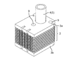
図4は、実施の形態1におけるプレートフィン積層体2の一部を示す斜視図である。図4においては、複数のプレートフィン2aを積層したプレートフィン積層体2を示すが、プレートフィン2aの積層すべき個数としては熱交換器1の仕様に応じて適宜設定される。図4に示すプレートフィン積層体2においては、エンドプレート3(3a、3b)が取り外されており、位置決めピン用開口9には位置決めピンが挿入されていない状態を示している。
FIG. 4 is a perspective view showing a part of the plate fin laminate 2 according to the first embodiment. FIG. 4 shows a plate fin laminate 2 in which a plurality of plate fins 2a are laminated, but the number of plate fins 2a to be laminated is appropriately set according to the specifications of the heat exchanger 1. In the plate fin laminate 2 shown in FIG. 4, the end plates 3 (3a, 3b) are removed, and the positioning pin is not inserted into the positioning pin opening 9.
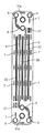
図5は、図4に示すプレートフィン積層体2におけるヘッダ流路11の近傍を示す斜視図である。図6は、図4のプレートフィン積層体2を図2Aに示すVI-VI線により切断した断面を示す斜視図である。図5および図6に示すように、プレートフィン積層体2におけるヘッダ流路11の内周側には積層方向に貫通するヘッダ開口11aが形成されている。ヘッダ開口11aには給入管4からヘッダ流路11への冷媒、またはヘッダ流路11から排出管5への冷媒が流れる。
FIG. 5 is a perspective view showing the vicinity of the header flow path 11 in the plate fin laminate 2 shown in FIG. FIG. 6 is a perspective view showing a cross section of the plate fin laminate 2 of FIG. 4 cut along the VI-VI line shown in FIG. 2A. As shown in FIGS. 5 and 6, a header opening 11a penetrating in the stacking direction is formed on the inner peripheral side of the header flow path 11 in the plate fin laminated body 2. The refrigerant from the supply pipe 4 to the header flow path 11 or the refrigerant from the header flow path 11 to the discharge pipe 5 flows through the header opening 11a.
プレートフィン積層体2において、積層方向に貫通するヘッダ開口11aの内面側を構成するヘッダ流路11の内周側は、ロウ付け加工により積層方向に連続して接合されている。また、ヘッダ流路11の外周側においても、積層方向に連続するように接合されている。この結果、プレートフィン積層体2におけるヘッダ流路11の内周側と外周側は積層方向に確実に接合された状態であり、ヘッダ流路11における剛性が高められている。
In the plate fin laminated body 2, the inner peripheral side of the header flow path 11 constituting the inner surface side of the header opening 11a penetrating in the laminating direction is continuously joined in the laminating direction by brazing. Further, the header flow path 11 is also joined so as to be continuous in the stacking direction on the outer peripheral side. As a result, the inner peripheral side and the outer peripheral side of the header flow path 11 in the plate fin laminated body 2 are in a state of being reliably joined in the stacking direction, and the rigidity of the header flow path 11 is increased.
給入管4から供給された冷媒は、ヘッダ開口11aを流れ、ヘッダ流路11の内周側に形成されたヘッダ流路口8(8a、8b)を通してヘッダ流路11に流れ込む構成である。図5および図6においては、ヘッダ流路11の内周側において対向する2つのヘッダ流路口8の一方の第1ヘッダ流路口8aが示されている。第1ヘッダ流路口8aと第2ヘッダ流路口8bは、ヘッダ開口11aの中心を通る長手方向に延びる中心線上、即ち、プレートフィン2aにおいて長手方向に延びる中心線上の対向する位置に配設されている。
The refrigerant supplied from the supply pipe 4 flows through the header opening 11a and flows into the header flow path 11 through the header flow path ports 8 (8a, 8b) formed on the inner peripheral side of the header flow path 11. In FIGS. 5 and 6, one first header flow path port 8a of the two header flow path ports 8 facing each other on the inner peripheral side of the header flow path 11 is shown. The first header flow path port 8a and the second header flow path port 8b are arranged on the center line extending in the longitudinal direction passing through the center of the header opening 11a, that is, at positions facing each other on the center line extending in the longitudinal direction in the plate fin 2a. There is.
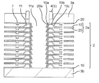
図7は、エンドプレート3(3a、3b)により挟まれた状態のプレートフィン積層体2におけるヘッダ開口11aの近傍を示す断面図である。図7の断面図は、図2Aに示すVI-VI線により切断した縦断面図である。図8は、図7に示した縦断面図の切断面に直交する長手方向の切断面を示す縦断面図である。図8は、プレートフィン積層体2におけるヘッダ開口11aの近傍を示しており、第1ヘッダ流路口8aと第2ヘッダ流路口8bとを含む断面図である。
FIG. 7 is a cross-sectional view showing the vicinity of the header opening 11a in the plate fin laminate 2 in a state of being sandwiched by the end plates 3 (3a, 3b). The cross-sectional view of FIG. 7 is a vertical cross-sectional view cut along the VI-VI line shown in FIG. 2A. FIG. 8 is a vertical cross-sectional view showing a cut surface in the longitudinal direction orthogonal to the cut surface of the vertical cross-sectional view shown in FIG. 7. FIG. 8 shows the vicinity of the header opening 11a in the plate fin laminated body 2, and is a cross-sectional view including the first header flow path port 8a and the second header flow path port 8b.
図7に示すように、プレートフィン積層体2は、第1フィン部材10と第2フィン部材20とを張り合わせて形成されたプレートフィン2aを複数積層して構成されている。第1フィン部材10においては、ヘッダ開口11aの外周にはヘッダ流路11を形成するための凹みが形成されている。第1フィン部材10におけるヘッダ流路11(凹み)は、ヘッダ開口11aの外周側の壁面を構成するヘッダ流路内周支持部10aと、ヘッダ流路頂部10bと、ヘッダ流路外周支持部10cとにより形成される。即ち、第1フィン部材10において、ヘッダ流路11を形成するための凹みは、頂部が環状に形成され平坦面を持つヘッダ流路頂部10bと、このヘッダ流路頂部10bを内周側で積層方向に支持する内周壁となるヘッダ流路内周支持部10aと、ヘッダ流路頂部10bを外周側で積層方向に支持する外周壁となるヘッダ流路外周支持部10cとにより構成されている。
As shown in FIG. 7, the plate fin laminated body 2 is configured by laminating a plurality of plate fins 2a formed by laminating the first fin member 10 and the second fin member 20. In the first fin member 10, a recess for forming the header flow path 11 is formed on the outer periphery of the header opening 11a. The header flow path 11 (recess) in the first fin member 10 includes a header flow path inner peripheral support portion 10a, a header flow path top portion 10b, and a header flow path outer peripheral support portion 10c that form a wall surface on the outer peripheral side of the header opening 11a. Is formed by. That is, in the first fin member 10, the recess for forming the header flow path 11 is formed by stacking the header flow path top portion 10b having a flat surface and the top portion formed in an annular shape and the header flow path top portion 10b on the inner peripheral side. It is composed of a header flow path inner peripheral support portion 10a which is an inner peripheral wall that supports in the direction, and a header flow path outer peripheral support portion 10c which is an outer peripheral wall that supports the header flow path top portion 10b in the stacking direction on the outer peripheral side.
一方、第2フィン部材20には、ヘッダ開口11aの外周の外縁部分となる内周支持部20aが形成されており、この内周支持部20aに続いて平坦部20bが形成されている。平坦部20bと内周支持部20aは屈曲して連続している。第2フィン部材20の内周支持部20aはヘッダ開口11aの外周側の壁面を構成する。第2フィン部材20の平坦部20bは、第1フィン部材10のヘッダ流路内周支持部10a、ヘッダ流路頂部10b、およびヘッダ流路外周支持部10cで構成される凹みを塞ぎ、ヘッダ開口11aの外周に環状のヘッダ流路11を構成する一部である。
On the other hand, the second fin member 20 is formed with an inner peripheral support portion 20a which is an outer peripheral portion of the outer periphery of the header opening 11a, and a flat portion 20b is formed following the inner peripheral support portion 20a. The flat portion 20b and the inner peripheral support portion 20a are bent and continuous. The inner peripheral support portion 20a of the second fin member 20 constitutes a wall surface on the outer peripheral side of the header opening 11a. The flat portion 20b of the second fin member 20 closes the recess formed by the header flow path inner peripheral support portion 10a, the header flow path top portion 10b, and the header flow path outer peripheral support portion 10c of the first fin member 10, and opens the header. It is a part of forming an annular header flow path 11 on the outer circumference of 11a.
上記のように、実施の形態1におけるプレートフィン積層体2の第1フィン部材10において、ヘッダ流路11を形成するための凹みは、ヘッダ流路内周支持部10aと、ヘッダ流路頂部10bと、ヘッダ流路外周支持部10cとを有している。ヘッダ流路内周支持部10aとヘッダ流路外周支持部10cが第2フィン部材20の平坦面に接合されてヘッダ流路が形成されており、ヘッダ流路内周支持部10aの一部にヘッダ流路口8が形成されている。
As described above, in the first fin member 10 of the plate fin laminate 2 according to the first embodiment, the recesses for forming the header flow path 11 are formed in the header flow path inner peripheral support portion 10a and the header flow path top portion 10b. And a header flow path outer peripheral support portion 10c. The header flow path inner peripheral support portion 10a and the header flow path outer peripheral support portion 10c are joined to the flat surface of the second fin member 20 to form a header flow path, which is part of the header flow path inner peripheral support portion 10a. The header flow path port 8 is formed.
また、第2フィン部材20は、平坦面を有する平坦部20bと、平坦部20bの平坦面に屈曲して連続し、ヘッダ流路11の内周側にあるヘッダ開口11aの外縁部分となる内周支持部20aと、を有している。第2フィン部材20の内周支持部20aが、積層方向に隣接する他のプレートフィン2aにおける第1フィン部材10に接合されて、プレートフィン積層体2におけるヘッダ流路11の内周側が積層方向に延びる2重壁面を有する構成となる。
Further, the second fin member 20 is bent and continuous with the flat portion 20b having a flat surface and the flat surface of the flat portion 20b, and serves as an outer edge portion of the header opening 11a on the inner peripheral side of the header flow path 11. It has a peripheral support portion 20a and a peripheral support portion 20a. The inner peripheral support portion 20a of the second fin member 20 is joined to the first fin member 10 in another plate fin 2a adjacent in the stacking direction, and the inner peripheral side of the header flow path 11 in the plate fin laminated body 2 is in the stacking direction. It has a structure having a double wall surface extending to.
また、図8の長手方向の縦断面図に示すように、ヘッダ流路11の内周側の対向する領域は、ヘッダ流路口8(8a、8b)を形成するために、第1フィン部材10のヘッダ流路内周支持部10aがヘッダ流路頂部10bからの突出長さが短く形成されている。同様に、第2フィン部材20の内周支持部20aの突出長さが短く形成されている。このように、ヘッダ流路内周支持部10aおよび内周支持部20aにおける長手方向で対向する領域が切り欠けられており、ヘッダ流路11の内周側にヘッダ流路口8(8a、8b)が形成されている。
Further, as shown in the longitudinal sectional view of FIG. 8, the facing region on the inner peripheral side of the header flow path 11 forms the header flow path port 8 (8a, 8b), so that the first fin member 10 is formed. The header flow path inner peripheral support portion 10a is formed to have a short protrusion length from the header flow path top portion 10b. Similarly, the protruding length of the inner peripheral support portion 20a of the second fin member 20 is formed to be short. As described above, the regions of the header flow path inner peripheral support portion 10a and the inner peripheral support portion 20a facing each other in the longitudinal direction are notched, and the header flow path ports 8 (8a, 8b) are formed on the inner peripheral side of the header flow path 11. Is formed.
図9は、図7に示した第1フィン部材10を示す縦断面図であり、ヘッダ開口11aの近傍における第1フィン部材10を示している。図10は、図7に示した第2フィン部材20を示す縦断面図であり、図9に示した第1フィン部材10と接合される部分を示している。図11は、図8に示した第1フィン部材10を示す縦断面図であり、ヘッダ開口11aの外周に形成されるヘッダ流路口8(8a、8b)が示されている。同様に、図12は、図8に示した第2フィン部材20を示す縦断面図であり、図11に示した第1フィン部材10と接合される部分を示している。
FIG. 9 is a vertical cross-sectional view showing the first fin member 10 shown in FIG. 7, and shows the first fin member 10 in the vicinity of the header opening 11a. FIG. 10 is a vertical cross-sectional view showing the second fin member 20 shown in FIG. 7, and shows a portion to be joined to the first fin member 10 shown in FIG. FIG. 11 is a vertical cross-sectional view showing the first fin member 10 shown in FIG. 8, and shows header flow path ports 8 (8a, 8b) formed on the outer periphery of the header opening 11a. Similarly, FIG. 12 is a vertical cross-sectional view showing the second fin member 20 shown in FIG. 8, and shows a portion to be joined to the first fin member 10 shown in FIG.
図9に示した第1フィン部材10と、図10に示した第2フィン部材20とが張り合わされて接合され、1枚のプレートフィン2aにおけるヘッダ開口11aの外周にヘッダ流路11が形成される。このようにヘッダ流路11が形成されるとき、図11に示した第1フィン部材10のヘッダ流路内周支持部10aと、図12に示した第2フィン部材20の内周支持部20aとにおいて、ヘッダ流路11におけるヘッダ流路口8(8a、8b)が形成され、ヘッダ開口11aがヘッダ流路口8(8a、8b)を介してヘッダ流路11の内部と連通する。
The first fin member 10 shown in FIG. 9 and the second fin member 20 shown in FIG. 10 are bonded and joined to form a header flow path 11 on the outer periphery of the header opening 11a in one plate fin 2a. The header. When the header flow path 11 is formed in this way, the header flow path inner peripheral support portion 10a of the first fin member 10 shown in FIG. 11 and the inner peripheral support portion 20a of the second fin member 20 shown in FIG. 12 The header flow path port 8 (8a, 8b) in the header flow path 11 is formed, and the header opening 11a communicates with the inside of the header flow path 11 via the header flow path port 8 (8a, 8b).
なお、図9に示すように、第1フィン部材10においては、ヘッダ流路内周支持部10aの内周側端部が内周側へ突出しており、内周側の突出端部10dが形成されている。この内周側の突出端部10dには、積層方向に隣接するプレートフィン2aにおける第2フィン部材20の内周支持部20aの内周側端部が当接している。このため、プレートフィン積層体2においては、第1フィン部材10の内周側の突出端部10dと第2フィン部材20の内周支持部20aの内周側端部が接合された状態となる(図7参照)。
As shown in FIG. 9, in the first fin member 10, the inner peripheral side end portion of the header flow path inner peripheral support portion 10a protrudes toward the inner peripheral side, and the inner peripheral side protruding end portion 10d is formed. Has been done. The inner peripheral side end portion of the inner peripheral support portion 20a of the second fin member 20 in the plate fins 2a adjacent in the stacking direction is in contact with the protruding end portion 10d on the inner peripheral side. Therefore, in the plate fin laminated body 2, the protruding end portion 10d on the inner peripheral side of the first fin member 10 and the inner peripheral side end portion of the inner peripheral support portion 20a of the second fin member 20 are joined to each other. (See FIG. 7).
前述のように、プレートフィン積層体2における各プレートフィン2aにおいては、ヘッダ流路11に接続されたヘッダ連通流路12が、第2フィン部材20に形成された受け渡し流路21を介して、第1プレートフィン流路13aに繋がる構成である。
As described above, in each plate fin 2a in the plate fin laminate 2, the header communication flow path 12 connected to the header flow path 11 is passed through the transfer flow path 21 formed in the second fin member 20. It is configured to be connected to the first plate fin flow path 13a.
図13は、プレートフィン積層体2を、その長手方向に沿って切断した縦断面を示す斜視図である。図13においては、各プレートフィン2aにおいて受け渡し流路21を介してヘッダ連通流路12と第1プレートフィン流路13aが連通している断面を示している。図14は、プレートフィン積層体2を長手方向に沿って切断した端面図であり、受け渡し流路21の近傍を示している。
FIG. 13 is a perspective view showing a vertical cross section of the plate fin laminate 2 cut along the longitudinal direction thereof. FIG. 13 shows a cross section in which the header communication flow path 12 and the first plate fin flow path 13a communicate with each other through the transfer flow path 21 in each plate fin 2a. FIG. 14 is an end view of the plate fin laminate 2 cut along the longitudinal direction, and shows the vicinity of the transfer flow path 21.
図13および図14に示すように、各プレートフィン2aにおいて第1フィン部材10に形成されたヘッダ連通流路12が、第2フィン部材20に形成された受け渡し流路21を介して、第1フィン部材10に形成されたプレートフィン流路13と連通している。従って、プレートフィン積層体2においては、例えば、給入管4から供給された冷媒は、ヘッダ開口11a、ヘッダ流路11、ヘッダ連通流路12、受け渡し流路21、およびプレートフィン流路13に流れる。このとき、図14に示す構成においては、ヘッダ連通流路12から受け渡し流路21へは下方へ冷媒が流れ、受け渡し流路21からプレートフィン流路13へは上方へ冷媒が流れる。即ち、受け渡し流路21の前後において冷媒は上下方向(積層方向)へうねりながら移動し、平面的な流路に比べて流路が長くなる構成となる。
As shown in FIGS. 13 and 14, the header communication flow path 12 formed in the first fin member 10 in each plate fin 2a is the first through the transfer flow path 21 formed in the second fin member 20. It communicates with the plate fin flow path 13 formed in the fin member 10. Therefore, in the plate fin laminate 2, for example, the refrigerant supplied from the supply pipe 4 flows through the header opening 11a, the header flow path 11, the header communication flow path 12, the transfer flow path 21, and the plate fin flow path 13. .. At this time, in the configuration shown in FIG. 14, the refrigerant flows downward from the header communication flow path 12 to the transfer flow path 21, and the refrigerant flows upward from the transfer flow path 21 to the plate fin flow path 13. That is, the refrigerant moves while swelling in the vertical direction (stacking direction) before and after the delivery flow path 21, and the flow path is longer than the flat flow path.
図15は、実施の形態1におけるプレートフィン積層体2を、その長手方向に直交する面で切断した縦断面を示す斜視図である。図16は、図15の縦断面を示すプレートフィン積層体2の端面図である。図15および図16に示すように、両端のエンドプレート3(3a、3b)の間に積層されたプレートフィン積層体2において、その上端にはプレートフィン2aの一方である第2フィン部材20が配設され、その下端にはプレートフィン2aの他方である第1フィン部材10が配設されている。
FIG. 15 is a perspective view showing a vertical cross section of the plate fin laminate 2 according to the first embodiment, which is cut along a plane orthogonal to the longitudinal direction thereof. FIG. 16 is an end view of the plate fin laminate 2 showing the vertical cross section of FIG. As shown in FIGS. 15 and 16, in the plate fin laminate 2 laminated between the end plates 3 (3a, 3b) at both ends, a second fin member 20 which is one of the plate fins 2a is located at the upper end thereof. A first fin member 10 which is the other side of the plate fin 2a is arranged at the lower end thereof.
実施の形態1の熱交換器は、両端のエンドプレート3における上側の第1エンドプレート3aの下面と、その直下に配設された第2フィン部材20の接合面が全面的に接触している。ここで接合面とは、プレートフィン2aにおいて第1フィン部材10と第2フィン部材20とが接合される面のことをいう。
In the heat exchanger of the first embodiment, the lower surface of the upper first end plate 3a in the end plates 3 at both ends and the joint surface of the second fin member 20 arranged immediately below the lower surface of the first end plate 3a are in complete contact with each other. .. Here, the joint surface means a surface on which the first fin member 10 and the second fin member 20 are joined in the plate fin 2a.
一方、プレートフィン積層体2の下端にはプレートフィン2aの他方である第1フィン部材10が配設されており、下側の第2エンドプレート3bの上面と第1フィン部材10の接合面が全面的に接触している。これは、上側の第1エンドプレート3aに対して、第1フィン部材10に接合する第2フィン部材20の接合面を対向させることにより、平坦面が広くなり、接触面積が大きくなるためである。同様に、下側の第2エンドプレート3bに対しては、第2フィン部材20に接合する第1フィン部材10の接合面を対向させることにより、平坦面が広くなり、接触面積が大きくなる。
On the other hand, a first fin member 10 which is the other side of the plate fins 2a is arranged at the lower end of the plate fin laminate 2, and the upper surface of the lower second end plate 3b and the joint surface of the first fin member 10 are arranged. It is in full contact. This is because the flat surface becomes wider and the contact area becomes larger by making the joint surface of the second fin member 20 to be joined to the first fin member 10 face the upper first end plate 3a. .. Similarly, by facing the joint surface of the first fin member 10 to be joined to the second fin member 20 with respect to the lower second end plate 3b, the flat surface becomes wider and the contact area becomes larger.
図17は、下側の第2エンドプレート3bに対して接触している第1フィン部材10、およびその上に積層されている第2フィン部材20と第1フィン部材10とで構成されるプレートフィン2aを示す分解斜視図である。図17は、積層方向における下方から見た斜視図である。図18は、上側の第1エンドプレート3aに対して接触している第2フィン部材20、およびその下に積層されている第1フィン部材10と第2フィン部材20とで構成されるプレートフィン2aを示す分解斜視図である。図18は、積層方向における上方から見た斜視図である。
FIG. 17 shows a plate composed of a first fin member 10 in contact with the lower second end plate 3b, and a second fin member 20 and a first fin member 10 laminated on the first fin member 10. It is an exploded perspective view which shows the fin 2a. FIG. 17 is a perspective view seen from below in the stacking direction. FIG. 18 shows a plate fin composed of a second fin member 20 in contact with the upper first end plate 3a, and a first fin member 10 and a second fin member 20 laminated under the second fin member 20. It is an exploded perspective view which shows 2a. FIG. 18 is a perspective view seen from above in the stacking direction.
図17および図18において、それぞれのフィン部材(10、20)で接触し接合される領域を斜線部分で示している。なお、プレートフィン2aを構成する第1フィン部材10と第2フィン部材20との間で接触する領域がロウ付けされる領域となる。図17および図18に示すように、エンドプレート3(3a、3b)と第1フィン部材10または第2フィン部材20とが接触する領域は広く全体的であるため、エンドプレート3に対して特別な加工を施すことなく第1フィン部材10または第2フィン部材20に対して略均等に接合されて、当該プレートフィン積層体2を確実に保持することが可能となる。
In FIGS. 17 and 18, the areas where the fin members (10, 20) are in contact with each other and are joined are shown by shaded areas. The area of contact between the first fin member 10 and the second fin member 20 constituting the plate fin 2a is a brazed area. As shown in FIGS. 17 and 18, the area of contact between the end plate 3 (3a, 3b) and the first fin member 10 or the second fin member 20 is wide and overall, and is therefore special to the end plate 3. The plate fin laminate 2 can be reliably held by being joined to the first fin member 10 or the second fin member 20 substantially evenly without any processing.
なお、プレートフィン積層体2の積層方向の両端に配設される第1フィン部材10および第2フィン部材20は、上記のようにエンドプレート3に接触しているため、給入管4からの冷媒は、当該第1フィン部材10および第2フィン部材20のヘッダ開口11aに流入する。しかしながら、第2エンドプレート3bに接触している第1フィン部材10においては、ヘッダ連通流路12から先が閉塞されて、平坦な流路受け渡し領域16となっている。このため、第2エンドプレート3bに接触している第1フィン部材10ではプレートフィン流路13に冷媒が流れ込むことはない。一方、第1エンドプレート3aに接触している第2フィン部材20は、流路としては受け渡し流路21のみが形成されている構成であり、ヘッダ流路11が形成されていないため、ヘッダ開口11aの冷媒が流れ込む流路が存在しない。
Since the first fin member 10 and the second fin member 20 arranged at both ends of the plate fin laminated body 2 in the stacking direction are in contact with the end plate 3 as described above, the refrigerant from the supply pipe 4 is used. Flows into the header opening 11a of the first fin member 10 and the second fin member 20. However, in the first fin member 10 in contact with the second end plate 3b, the tip of the header communication flow path 12 is blocked to form a flat flow path transfer region 16. Therefore, in the first fin member 10 in contact with the second end plate 3b, the refrigerant does not flow into the plate fin flow path 13. On the other hand, the second fin member 20 in contact with the first end plate 3a has a configuration in which only the transfer flow path 21 is formed as the flow path, and the header flow path 11 is not formed, so that the header opening There is no flow path through which the refrigerant of 11a flows.
上記のように実施の形態1の熱交換器1の構成では、プレートフィン積層体2の積層方向の両端にプレートフィン2aを構成する部材の一方を配設することにより、エンドプレート3に対して特別な加工を施すことなく、プレートフィン積層体2を確実に保持することが可能となる。エンドプレート3により保持されるプレートフィン積層体2は、プレートフィン2aにおける長手方向の両側に設けられたヘッダ流路11が形成されたヘッダ領域の間の領域が熱交換領域Cとなり、その熱交換領域Cに所望形状のプレートフィン流路13が形成されている。この熱交換領域Cに形成されているプレートフィン流路13に対しては、第2流体Bである空気が効率高く接触して流れるように、積層されたプレートフィン2aの熱交換領域Cの間は所定隙間を有している。前述のように、積層方向に隣接するプレートフィン2aの間の隙間は、第1エンドプレート3aおよび/または第2エンドプレート3bに設けられた複数の間隔規定突起7(図2B参照)により確保されている。
As described above, in the configuration of the heat exchanger 1 of the first embodiment, one of the members constituting the plate fins 2a is arranged at both ends of the plate fin laminated body 2 in the stacking direction, so that the end plate 3 is The plate fin laminate 2 can be reliably held without any special processing. In the plate fin laminate 2 held by the end plate 3, the region between the header regions where the header flow paths 11 provided on both sides in the longitudinal direction of the plate fins 2a are formed becomes the heat exchange region C, and the heat exchange thereof. A plate fin flow path 13 having a desired shape is formed in the region C. Between the heat exchange regions C of the laminated plate fins 2a so that the air, which is the second fluid B, can efficiently contact and flow with respect to the plate fin flow path 13 formed in the heat exchange region C. Has a predetermined gap. As described above, the gap between the plate fins 2a adjacent to each other in the stacking direction is secured by a plurality of spacing defining protrusions 7 (see FIG. 2B) provided on the first end plate 3a and / or the second end plate 3b. ing.
上記のように構成された実施の形態1の熱交換器1は、ヘッダ流路11が第1フィン部材10のヘッダ流路内周支持部10aと、ヘッダ流路頂部10bと、ヘッダ流路外周支持部10cとにより構成された凹みと、第2フィン部材20の実質的な平坦面で構成された平坦部20bとで形成されており、ヘッダ流路内周支持部10aに形成されたヘッダ流路口8を介して給入管4からの冷媒が供給される構成である。
In the heat exchanger 1 of the first embodiment configured as described above, the header flow path 11 has the header flow path inner peripheral support portion 10a of the first fin member 10, the header flow path top portion 10b, and the header flow path outer circumference. A header flow formed by a recess formed by the support portion 10c and a flat portion 20b formed by a substantially flat surface of the second fin member 20 and formed in the header flow path inner peripheral support portion 10a. The refrigerant is supplied from the supply pipe 4 through the road opening 8.
実施の形態1のプレートフィン積層体2は、各プレートフィン2aにおけるヘッダ開口11aの外周に形成されるヘッダ流路11が、第1フィン部材10のヘッダ流路内周支持部10aの内周側とヘッダ流路外周支持部10cの外周側で接合されている。また、積層されたプレートフィン2aでは、積層方向に隣接するヘッダ流路が接合されている。このため、実施の形態1におけるヘッダ流路11は、剛性の高い構成となっており、給入管4からの高圧の冷媒がヘッダ開口11aからヘッダ流路口8を通してヘッダ流路11に供給されても、ヘッダ流路11が拡張される等の変形することが抑制される構成であり、所望形状の流路が確実に維持される構成となる。従って、実施の形態1の熱交換器1においては、効率の高い熱交換を信頼性高く行うことができる。
In the plate fin laminate 2 of the first embodiment, the header flow path 11 formed on the outer periphery of the header opening 11a in each plate fin 2a is on the inner peripheral side of the header flow path inner peripheral support portion 10a of the first fin member 10. Is joined on the outer peripheral side of the header flow path outer peripheral support portion 10c. Further, in the stacked plate fins 2a, header flow paths adjacent to each other in the stacking direction are joined. Therefore, the header flow path 11 in the first embodiment has a highly rigid configuration, and even if the high-pressure refrigerant from the supply pipe 4 is supplied to the header flow path 11 from the header opening 11a through the header flow path port 8. , The header flow path 11 is prevented from being deformed such as being expanded, and the flow path having a desired shape is surely maintained. Therefore, in the heat exchanger 1 of the first embodiment, highly efficient heat exchange can be performed with high reliability.
上記のように、実施の形態1の熱交換器1においては、第1フィン部材10と第2フィン部材20との積層構造により、各プレートフィン2aにおけるヘッダ流路の強度を高めると共に、プレートフィン積層体2における軽量化、小型化および熱交換の効率化を達成することが可能となる。実施の形態1の構成によれば、高圧の冷媒を流路に流すことが可能な信頼性が高い熱交換器を提供することができる。
As described above, in the heat exchanger 1 of the first embodiment, the laminated structure of the first fin member 10 and the second fin member 20 enhances the strength of the header flow path in each plate fin 2a and plate fins. It is possible to achieve weight reduction, miniaturization, and efficiency of heat exchange in the laminated body 2. According to the configuration of the first embodiment, it is possible to provide a highly reliable heat exchanger capable of flowing a high-pressure refrigerant through the flow path.
なお、前述の実施の形態1の構成においては、プレートフィン2aのヘッダ流路11の内周側が、第1フィン部材10のヘッダ流路内周支持部10aと、第2フィン部材20の内周支持部20aとの2重構造の壁面で構成されている。この結果、実施の形態1の熱交換器1は、給入管4から冷媒が供給されるヘッダ流路11の内周側の強度が高められており、高圧の冷媒をヘッダ流路11に流すことが可能な構成となる。
In the configuration of the first embodiment described above, the inner circumference side of the header flow path 11 of the plate fin 2a is the inner circumference of the header flow path inner circumference support portion 10a of the first fin member 10 and the second fin member 20. It is composed of a wall surface having a double structure with a support portion 20a. As a result, in the heat exchanger 1 of the first embodiment, the strength of the inner peripheral side of the header flow path 11 to which the refrigerant is supplied from the supply pipe 4 is increased, and the high-pressure refrigerant flows into the header flow path 11. Is possible.
また、実施の形態1の構成においては、熱交換器1の両端に設けたエンドプレート3に対して、プレートフィン2aを構成する第1フィン部材10または第2フィン部材20の接合面を接触させるように構成されている。このため、エンドプレート3に特別な加工を施すことなく、確実にプレートフィン積層体2を挟着できる構成であると共に、エンドプレート3に接触している第1フィン部材10または第2フィン部材20においては、特別な加工を施すことなく冷媒の流れを防止できる構成となっており、エンドプレート3において冷媒が漏れることが防止されている。
Further, in the configuration of the first embodiment, the joint surfaces of the first fin member 10 or the second fin member 20 constituting the plate fin 2a are brought into contact with the end plates 3 provided at both ends of the heat exchanger 1. It is configured as follows. Therefore, the plate fin laminate 2 can be reliably sandwiched without any special processing on the end plate 3, and the first fin member 10 or the second fin member 20 in contact with the end plate 3 can be reliably sandwiched. In the above, the structure is such that the flow of the refrigerant can be prevented without any special processing, and the leakage of the refrigerant is prevented in the end plate 3.
[変形例]
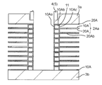
図19は、実施の形態1の構成における変形例を模式的に示す縦断面図である。図19は、第1フィン部材10Aと第2フィン部材20Aにおけるヘッダ流路11の近傍を示している。図19に示すように、第1フィン部材10Aにおけるヘッダ流路11を形成する凹みは、環状に形成され平坦面を有するヘッダ流路頂部10Abと、このヘッダ流路頂部10Abを内周側と外周側の両方で積層方向に支持するように形成されたヘッダ流路支持部(ヘッダ流路内周支持部10Aa、ヘッダ流路外周支持部10Ac)とにより構成されている。なお、ヘッダ流路頂部10Abを外周側で支持するヘッダ流路外周支持部10Acは、プレートフィン流路13が形成されている熱交換領域Cに屈曲部を介して連続している。図19の縦断面図に示すように、ヘッダ流路11を形成するための凹みは、ヘッダ流路内周支持部10Aaと、ヘッダ流路頂部10Abと、ヘッダ流路外周支持部10Acとの間が屈曲してコの字状に連続しており、流路方向に直交する断面が略四角形状の流路となっている。 [Modification example]
FIG. 19 is a vertical cross-sectional view schematically showing a modified example of the configuration of the first embodiment. FIG. 19 shows the vicinity of theheader flow path 11 in the first fin member 10A and the second fin member 20A. As shown in FIG. 19, the recess forming the header flow path 11 in the first fin member 10A includes a header flow path top portion 10Ab formed in an annular shape and having a flat surface, and the header flow path top portion 10Ab on the inner peripheral side and the outer peripheral side. It is composed of a header flow path support portion (header flow path inner peripheral support portion 10Aa, header flow path outer peripheral support portion 10Ac) formed so as to support in the stacking direction on both sides. The header flow path outer peripheral support portion 10Ac that supports the header flow path top portion 10Ab on the outer peripheral side is continuous with the heat exchange region C in which the plate fin flow path 13 is formed via a bent portion. As shown in the vertical cross-sectional view of FIG. 19, the recess for forming the header flow path 11 is between the header flow path inner peripheral support portion 10Aa, the header flow path top portion 10Ab, and the header flow path outer peripheral support portion 10Ac. Is bent and continuous in a U shape, and the cross section orthogonal to the flow path direction is a substantially square flow path.
図19は、実施の形態1の構成における変形例を模式的に示す縦断面図である。図19は、第1フィン部材10Aと第2フィン部材20Aにおけるヘッダ流路11の近傍を示している。図19に示すように、第1フィン部材10Aにおけるヘッダ流路11を形成する凹みは、環状に形成され平坦面を有するヘッダ流路頂部10Abと、このヘッダ流路頂部10Abを内周側と外周側の両方で積層方向に支持するように形成されたヘッダ流路支持部(ヘッダ流路内周支持部10Aa、ヘッダ流路外周支持部10Ac)とにより構成されている。なお、ヘッダ流路頂部10Abを外周側で支持するヘッダ流路外周支持部10Acは、プレートフィン流路13が形成されている熱交換領域Cに屈曲部を介して連続している。図19の縦断面図に示すように、ヘッダ流路11を形成するための凹みは、ヘッダ流路内周支持部10Aaと、ヘッダ流路頂部10Abと、ヘッダ流路外周支持部10Acとの間が屈曲してコの字状に連続しており、流路方向に直交する断面が略四角形状の流路となっている。 [Modification example]
FIG. 19 is a vertical cross-sectional view schematically showing a modified example of the configuration of the first embodiment. FIG. 19 shows the vicinity of the
一方、第1フィン部材10Aに接合される第2フィン部材20Aは、各プレートフィン2Aaにおいてヘッダ流路11を形成するために、図19に示すように、ヘッダ流路内周支持部10Aa、ヘッダ流路頂部10Ab、およびヘッダ流路外周支持部10Acにより構成される凹みを覆うように平坦な面である平坦部20Abを有する。図19に示す変形例における第2フィン部材20Aは、前述の図6に示した第2フィン部材20の内周支持部20aとは異なり、第2フィン部材20Aの内周側端部が垂れ下がるような形状ではない。
On the other hand, in order to form the header flow path 11 in each plate fin 2Aa, the second fin member 20A joined to the first fin member 10A has the header flow path inner peripheral support portion 10Aa and the header as shown in FIG. It has a flat portion 20Ab which is a flat surface so as to cover a recess formed by a flow path top portion 10Ab and a header flow path outer peripheral support portion 10Ac. The second fin member 20A in the modified example shown in FIG. 19 is different from the inner peripheral support portion 20a of the second fin member 20 shown in FIG. 6 described above, so that the inner peripheral side end portion of the second fin member 20A hangs down. It is not a good shape.
従って、この変形例のプレートフィン積層体2Aにおいては、ヘッダ流路11の内周側が第1フィン部材10Aのヘッダ流路内周支持部10Aaで構成されており、プレートフィン2Aaのヘッダ流路11の内周側が1重構造となっている。図19において、ヘッダ流路内周支持部10Aaの下端となる導出端は、第2フィン部材20Aの内周側先端部分に接合されている。ヘッダ流路内周支持部10Aaの上端に繋がるヘッダ流路頂部10Abは、積層方向に隣接するプレートフィン2Aaの第2フィン部材20Aの平坦部20Abに接合されている。即ち、図19に示す変形例のヘッダ流路11の内周側と外周側は、積層方向の上下に接合されて繋がった壁面となるヘッダ流路支持部で構成される。
Therefore, in the plate fin laminate 2A of this modification, the inner peripheral side of the header flow path 11 is composed of the header flow path inner peripheral support portion 10Aa of the first fin member 10A, and the header flow path 11 of the plate fin 2Aa. The inner peripheral side of is a single structure. In FIG. 19, the lead-out end, which is the lower end of the header flow path inner peripheral support portion 10Aa, is joined to the inner peripheral side tip portion of the second fin member 20A. The header flow path top portion 10Ab connected to the upper end of the header flow path inner peripheral support portion 10Aa is joined to the flat portion 20Ab of the second fin member 20A of the plate fins 2Aa adjacent in the stacking direction. That is, the inner peripheral side and the outer peripheral side of the header flow path 11 of the modified example shown in FIG. 19 are composed of a header flow path support portion which is a wall surface which is joined and connected vertically in the stacking direction.
この結果、変形例のプレートフィン積層体2Aにおいては、内周側が1重構造であってもヘッダ流路11が剛性の高い構成となっている。また、積層するプレートフィン2Aaにおけるヘッダ流路11の内周側は、1重構造であるが、各層が連続的に接合されているため、剛性の高い冷媒通路が形成されている。この冷媒通路には、積層毎にヘッダ流路口8が形成されており、各層のプレートフィン2Aaのヘッダ流路11に対して圧力の高い冷媒が供給可能な構成となる。
As a result, in the modified plate fin laminate 2A, the header flow path 11 has a high rigidity even if the inner peripheral side has a single structure. Further, the inner peripheral side of the header flow path 11 in the plate fins 2Aa to be laminated has a single structure, but since each layer is continuously joined, a highly rigid refrigerant passage is formed. A header flow path port 8 is formed in this refrigerant passage for each stacking, so that a high-pressure refrigerant can be supplied to the header flow path 11 of the plate fins 2Aa of each layer.
なお、図19に示す変形例におけるその他の構成(例えば、ヘッダ連通流路12、プレートフィン流路13、受け渡し流路21など)は、実施の形態1において説明した構成と同じである。
Other configurations (for example, header communication flow path 12, plate fin flow path 13, transfer flow path 21, etc.) in the modified example shown in FIG. 19 are the same as the configurations described in the first embodiment.
(実施の形態2)
次に、本開示に係る実施の形態2の積層型プレートフィン熱交換器(以下、単に熱交換器と称する)について説明する。図20は、実施の形態2の熱交換器におけるプレートフィン積層体100を示す斜視図である。図21は、実施の形態2におけるプレートフィン積層体100において、ヘッダ流路130が形成されている領域の断面図である。 (Embodiment 2)
Next, the laminated plate fin heat exchanger of the second embodiment according to the present disclosure (hereinafter, simply referred to as a heat exchanger) will be described. FIG. 20 is a perspective view showing aplate fin laminate 100 in the heat exchanger of the second embodiment. FIG. 21 is a cross-sectional view of a region where the header flow path 130 is formed in the plate fin laminate 100 according to the second embodiment.
次に、本開示に係る実施の形態2の積層型プレートフィン熱交換器(以下、単に熱交換器と称する)について説明する。図20は、実施の形態2の熱交換器におけるプレートフィン積層体100を示す斜視図である。図21は、実施の形態2におけるプレートフィン積層体100において、ヘッダ流路130が形成されている領域の断面図である。 (Embodiment 2)
Next, the laminated plate fin heat exchanger of the second embodiment according to the present disclosure (hereinafter, simply referred to as a heat exchanger) will be described. FIG. 20 is a perspective view showing a
図20および図21において、前述の実施の形態1と実質的に同一の機能、構成を有する要素には同じ番号を付与している。また、実施の形態2の熱交換器としての基本的な動作は、実施の形態1の熱交換器1の動作と同じであるので、実施の形態2においては実施の形態1と異なる点を主として説明する。実施の形態2の熱交換器において、実施の形態1の熱交換器1と大きく異なる点は、ヘッダ流路の形状である。
In FIGS. 20 and 21, the same numbers are assigned to the elements having substantially the same functions and configurations as those in the first embodiment. Further, since the basic operation of the heat exchanger of the second embodiment is the same as that of the heat exchanger 1 of the first embodiment, the second embodiment is mainly different from the first embodiment. explain. The heat exchanger of the second embodiment is significantly different from the heat exchanger 1 of the first embodiment in the shape of the header flow path.
図20および図21に示すように、実施の形態1の構成と同様に、第1フィン部材110と第2フィン部材120が接合(ロウ付け)されて1枚のプレートフィン100aが形成される。実施の形態2における第1フィン部材110および第2フィン部材120のそれぞれには、ヘッダ流路130が形成される対向位置に環状の凹みを有している。第1フィン部材110と第2フィン部材120が接合されることにより、ヘッダ流路130が形成される。従って、実施の形態2におけるヘッダ流路130は、その流路の流れ方向に直交する断面が実施の形態1におけるヘッダ流路11に比べて大きく(例えば、同様のプレートフィンであれば流路方向に直交する断面積が略2倍)形成される。
As shown in FIGS. 20 and 21, the first fin member 110 and the second fin member 120 are joined (brazed) to form one plate fin 100a, as in the configuration of the first embodiment. Each of the first fin member 110 and the second fin member 120 in the second embodiment has an annular recess at an opposite position where the header flow path 130 is formed. The header flow path 130 is formed by joining the first fin member 110 and the second fin member 120. Therefore, the header flow path 130 in the second embodiment has a cross section orthogonal to the flow direction of the flow path larger than that of the header flow path 11 in the first embodiment (for example, in the case of similar plate fins, the flow path direction). The cross-sectional area orthogonal to is approximately doubled).
実施の形態2における第1フィン部材110の表面側には積層方向に隣接するプレートフィン100aとの間の距離を確保するために、間隔規定突起7が全体的に複数形成されている。これらの間隔規定突起7の配設位置としては、実施の形態1における第2フィン部材20(図2B参照)と同様に、積層方向に隣接するプレートフィン100aとの間の距離が均等になるように分散して配置されている。また、第1フィン部材110には、プレートフィン積層体100の長手方向に直交する方向に並んで、ヘッダ流路130の両側に位置決めピン用開口9が形成されている。即ち、ヘッダ流路130および位置決めピン用開口9は、プレートフィン積層体100の長手方向に直交する方向に一列に配置され、第2流体Bである空気の流れ方向と並行に配設されている。
A plurality of spacing defining protrusions 7 are formed on the surface side of the first fin member 110 in the second embodiment as a whole in order to secure a distance between the plate fins 100a adjacent to each other in the stacking direction. As for the arrangement position of these spacing defining protrusions 7, the distance between the plate fins 100a adjacent to each other in the stacking direction is equal as in the second fin member 20 (see FIG. 2B) in the first embodiment. It is distributed and arranged in. Further, the first fin member 110 is formed with positioning pin openings 9 on both sides of the header flow path 130 so as to be arranged in a direction orthogonal to the longitudinal direction of the plate fin laminate 100. That is, the header flow path 130 and the positioning pin opening 9 are arranged in a row in a direction orthogonal to the longitudinal direction of the plate fin laminate 100, and are arranged in parallel with the flow direction of the air which is the second fluid B. ..
実施の形態2における第2フィン部材120には、実施の形態1における第1フィン部材10と同様に、ヘッダ連通流路12、およびプレートフィン流路13が形成されている(図2A参照)。従って、第2フィン部材120のヘッダ連通流路12とプレートフィン流路13とを連通させるために、第1フィン部材110には受け渡し流路21が形成されている(図20参照)。
The second fin member 120 in the second embodiment is formed with the header communication flow path 12 and the plate fin flow path 13 as in the first fin member 10 in the first embodiment (see FIG. 2A). Therefore, in order to communicate the header communication flow path 12 of the second fin member 120 with the plate fin flow path 13, the first fin member 110 is formed with a transfer flow path 21 (see FIG. 20).
実施の形態2における熱交換器において、実施の形態1の熱交換器1と同様に、給入管4からの高圧の冷媒がヘッダ流路130に供給されるために、ヘッダ流路130の内周側にはヘッダ流路口80が形成されている(図21参照)。実施の形態2におけるヘッダ流路口80は、ヘッダ流路130を形成する第1フィン部材110の内周側端部の一部を切欠いて形成されている。
In the heat exchanger according to the second embodiment, similarly to the heat exchanger 1 of the first embodiment, the high-pressure refrigerant from the supply pipe 4 is supplied to the header flow path 130, so that the inner circumference of the header flow path 130 is supplied. A header flow path port 80 is formed on the side (see FIG. 21). The header flow path port 80 in the second embodiment is formed by cutting out a part of the inner peripheral side end portion of the first fin member 110 forming the header flow path 130.
図21に示すように、1枚のプレートフィン100aを構成する第1フィン部材110と第2フィン部材120とにおいて、ヘッダ流路130の内周側と外周側が接合(ロウ付け)される領域となる。このため、ヘッダ流路130においては、高圧の冷媒がヘッダ流路口80から吸入される構成において、ヘッダ流路の変形が防止される構成であり、信頼性の高いヘッダ流路を有している。
As shown in FIG. 21, in the first fin member 110 and the second fin member 120 constituting one plate fin 100a, a region where the inner peripheral side and the outer peripheral side of the header flow path 130 are joined (brazed). Become. Therefore, in the header flow path 130, the header flow path is prevented from being deformed in the configuration in which the high-pressure refrigerant is sucked from the header flow path port 80, and has a highly reliable header flow path. ..
なお、実施の形態2の構成において、ヘッダ流路口80は、ヘッダ流路130の内周側における対向する位置に形成されており、環状のヘッダ流路130の中心を通るプレートフィン100aの長手方向に延びる中心線上の位置に形成されている。このように、ヘッダ流路口80をヘッダ流路130の長手方向の位置に対向して形成することにより、当該熱交換器が装置(例えば、空調機器)に備えられた状態においては、プレートフィン積層体100が、その長手方向に対して鉛直線から所定角度傾いて、例えば45度傾いて設けられているため、対向するヘッダ流路口80は鉛直方向の上下位置となる。このため、給入管4の冷媒が、液相とガス相の状態で分かれて流れている場合には、上下位置にあるヘッダ流路口80には液相とガス相の冷媒が供給される。この結果、熱交換領域における積層された各層のプレートフィン流路13に対して液相とガス相のバランスのとれた同様の冷媒が供給され、プレートフィン積層体100の全体的にバランスのとれた効率の高い熱交換を行うことが可能な構成となる。
In the configuration of the second embodiment, the header flow path port 80 is formed at a position facing the inner peripheral side of the header flow path 130, and is in the longitudinal direction of the plate fin 100a passing through the center of the annular header flow path 130. It is formed at a position on the center line extending to. By forming the header flow path port 80 so as to face the position in the longitudinal direction of the header flow path 130 in this way, the plate fins are laminated in a state where the heat exchanger is provided in the device (for example, air conditioning equipment). Since the body 100 is provided at an angle of a predetermined angle from the vertical direction with respect to the longitudinal direction thereof, for example, at an angle of 45 degrees, the header flow path port 80 facing the body 100 is in a vertical position in the vertical direction. Therefore, when the refrigerant of the supply pipe 4 flows separately in the state of the liquid phase and the gas phase, the refrigerant of the liquid phase and the gas phase is supplied to the header flow path ports 80 at the upper and lower positions. As a result, a similar refrigerant with a balanced liquid phase and gas phase was supplied to the plate fin flow paths 13 of the laminated layers in the heat exchange region, and the plate fin laminated body 100 was generally balanced. The configuration is such that highly efficient heat exchange can be performed.
実施の形態1及び実施の形態2の構成において、ヘッダ流路としては、円環状の形状の構成で説明したが、本開示はこの形状に特定されるものではなく、単なる環状の形状の他に、例えばC形状や円弧形状のように環状に繋がっていない流路形状などの各種形状を含むものである。
In the configurations of the first embodiment and the second embodiment, the header flow path has been described as having an annular shape, but the present disclosure is not specified in this shape, and is not limited to a simple annular shape. For example, it includes various shapes such as a C shape and an arc shape that are not connected in a ring shape.
本開示によれば、軽量化、小型化および効率化を達成すると共に、高圧の冷媒が流れる構成であっても信頼性の高い熱交換器を提供することができる。
According to the present disclosure, it is possible to achieve weight reduction, miniaturization, and efficiency, and to provide a highly reliable heat exchanger even in a configuration in which a high-pressure refrigerant flows.
本開示の熱交換器は、実施の形態1及び実施の形態2で説明したように、ヘッダ流路としては、ヘッダ流路の内周側から冷媒が供給される構成であり、且つプレートフィン積層体における各層のヘッダ流路の内周側および外周側が接合されて、剛性の高い構成となっている。このような構成された熱交換器においては、所望の高い圧力の冷媒をプレートフィン積層体に供給することが可能となり、効率の高い熱交換機能を有する構成となる。
As described in the first and second embodiments, the heat exchanger of the present disclosure has a header flow path in which the refrigerant is supplied from the inner peripheral side of the header flow path, and the plate fins are laminated. The inner peripheral side and the outer peripheral side of the header flow path of each layer in the body are joined to form a highly rigid structure. In the heat exchanger configured in this way, it is possible to supply a refrigerant having a desired high pressure to the plate fin laminate, and the heat exchanger has a highly efficient heat exchange function.
本開示の熱交換器のプレートフィン積層体において、積層方向に連なる多層支持部(ヘッダ流路内周支持部、ヘッダ流路外周支持部)によりヘッダ流路が構成されているため、ヘッダ流路における耐圧脆弱性が大幅に緩和されており、ヘッダ流路の剛性が高められている。この結果、本開示の熱交換器においては、一定以上の高い圧力の冷媒を流す場合であっても、安定した動作を維持することができる。
In the plate fin laminate of the heat exchanger of the present disclosure, since the header flow path is formed by the multilayer support portions (header flow path inner peripheral support portion, header flow path outer peripheral support portion) connected in the stacking direction, the header flow path is formed. The pressure resistance vulnerability in the header is greatly reduced, and the rigidity of the header flow path is increased. As a result, in the heat exchanger of the present disclosure, stable operation can be maintained even when a refrigerant having a pressure higher than a certain level is flowed.
また、本開示の熱交換器のプレートフィン積層体においては、ヘッダ流路の内周側の支持部にヘッダ流路口を形成して、このヘッダ流路口が各プレートフィンの流路に対する最初の流通口としている。ヘッダ流路のヘッダ流路口は、その開口形状および形成位置を適宜設定することが可能である構成であるため、本開示の熱交換器においては理想的な冷媒状態(液相-ガス層のバランス状態)に最適化することができ、更なる高性能化が可能な構成である。
Further, in the plate fin laminate of the heat exchanger of the present disclosure, a header flow path port is formed in a support portion on the inner peripheral side of the header flow path, and this header flow path port is the first flow to the flow path of each plate fin. I'm talking. Since the header flow path port of the header flow path has a configuration in which the opening shape and formation position can be appropriately set, the ideal refrigerant state (liquid phase-gas layer balance) in the heat exchanger of the present disclosure is used. It is a configuration that can be optimized for the state) and further improve the performance.
更に、本開示に係る熱交換器の構成においては、積層されたプレートフィンのプレートフィン積層体の全体として接合されて剛性を有する構成となっているため、エンドプレートを比較的に薄い金属材料により構成することができる。エンドプレートは、積層されたプレートフィンに対する位置決め用の部材が装着され、給排管が装着される構成であるため、プレートフィン積層体を積層方向に強く挟着するために厚みの厚い剛性の高い材料を用いる必要がない。この結果、本開示の熱交換器におけるエンドプレートは、接合されるプレートフィンとの熱容量が大きく異なることがなく、また部材強度が大きく異なることがないため、エンドプレートとプレートフィンとの間でロウ付け不良が発生することが大幅に抑制されている。従って、本開示の熱交換器は、供給される冷媒に対する耐圧性を有し、高い信頼性を有する構成である。
Further, in the configuration of the heat exchanger according to the present disclosure, since the plate fin laminate of the laminated plate fins is joined as a whole to have rigidity, the end plate is made of a relatively thin metal material. Can be configured. Since the end plate is configured to be equipped with a member for positioning the laminated plate fins and a supply / discharge pipe, the plate fin laminates are strongly sandwiched in the stacking direction, so that the end plates are thick and highly rigid. There is no need to use materials. As a result, the end plates in the heat exchanger of the present disclosure do not have a large difference in heat capacity from the plate fins to be joined, and the member strengths do not differ significantly. The occurrence of poor attachment is greatly suppressed. Therefore, the heat exchanger of the present disclosure has a pressure resistance to the supplied refrigerant and has a highly reliable configuration.
上記のように、本開示に係る熱交換器の構成においては、軽量化、小型化および高い熱交換の効率化を達成することができると共に、プレートフィン積層体における各層のプレートフィンに高圧の冷媒を流すことが可能な構成であり、信頼性が高く、熱交換効率の高い熱交換器を提供することができる。
As described above, in the configuration of the heat exchanger according to the present disclosure, weight reduction, miniaturization, and high efficiency of heat exchange can be achieved, and a high-pressure refrigerant is applied to the plate fins of each layer in the plate fin laminate. It is possible to provide a heat exchanger having a high reliability and a high heat exchange efficiency.
本開示をある程度の詳細さをもって各実施の形態において説明したが、これらの構成は例示であり、これらの実施の形態の開示内容は構成の細部において変化してしかるべきものである。本開示においては、各実施の形態における要素の置換、組合せ、および順序の変更は請求された範囲及び思想を逸脱することなく実現し得るものである。
Although the present disclosure has been described in each embodiment with some detail, these configurations are examples, and the disclosure content of these embodiments should vary in the details of the configuration. In the present disclosure, substitutions, combinations, and sequence changes of elements in each embodiment can be realized without departing from the claimed scope and ideas.
本開示は、軽量化、小型化および高い熱交換の効率化を達成することができる信頼性の高い熱交換器を提供することができるため、市場価値が高い空調機器を構築することができる。
The present disclosure can provide a highly reliable heat exchanger that can achieve weight reduction, miniaturization, and high efficiency of heat exchange, so that an air conditioner having a high market value can be constructed.
1 熱交換器
2,2A,100 プレートフィン積層体
2a,2Aa,100a プレートフィン
3 エンドプレート
3a 第1エンドプレート
3b 第2エンドプレート
4 給入管
5 排出管
6 伝熱遮断スリット
7 間隔規定突起
8,80 ヘッダ流路口
8a 第1ヘッダ流路口
8b 第2ヘッダ流路口
9 位置決めピン用開口
10,10A,110 第1フィン部材
10a,10Aa ヘッダ流路内周支持部
10b,10Ab ヘッダ流路頂部
10c,10Ac ヘッダ流路外周支持部
10d 内周側の突出端部
11,130 ヘッダ流路
11a ヘッダ開口
12 ヘッダ連通流路
13 プレートフィン流路
13a 第1プレートフィン流路(直線状)
13b 第2プレートフィン流路(円弧状)
16 流路受け渡し領域
20,20A,120 第2フィン部材
20a 内周支持部
20b,20Ab 平坦部
21 受け渡し流路 1 Heat exchanger 2,2A, 100 Plate fin laminate 2a, 2Aa, 100a Plate fin 3 End plate 3a 1st end plate 3b 2nd end plate 4 Feed pipe 5 Discharge pipe 6 Heat transfer cutoff slit 7 Interval regulation protrusion 8, 80 Header flow path port 8a 1st header flow path port 8b 2nd header flow path port 9 Positioning pin openings 10, 10A, 110 1st fin member 10a, 10Aa Header flow path inner peripheral support 10b, 10Ab Header flow path top 10c, 10Ac Header flow path Outer circumference support part 10d Protruding end on the inner circumference side 11,130 Header flow path 11a Header opening 12 Header communication flow path 13 Plate fin flow path 13a First plate fin flow path (straight)
13b 2nd plate fin flow path (arc-shaped)
16 Flow path transfer area 20, 20A, 120 Second fin member 20a Inner circumference support portion 20b, 20Ab Flat portion 21 Delivery flow path
2,2A,100 プレートフィン積層体
2a,2Aa,100a プレートフィン
3 エンドプレート
3a 第1エンドプレート
3b 第2エンドプレート
4 給入管
5 排出管
6 伝熱遮断スリット
7 間隔規定突起
8,80 ヘッダ流路口
8a 第1ヘッダ流路口
8b 第2ヘッダ流路口
9 位置決めピン用開口
10,10A,110 第1フィン部材
10a,10Aa ヘッダ流路内周支持部
10b,10Ab ヘッダ流路頂部
10c,10Ac ヘッダ流路外周支持部
10d 内周側の突出端部
11,130 ヘッダ流路
11a ヘッダ開口
12 ヘッダ連通流路
13 プレートフィン流路
13a 第1プレートフィン流路(直線状)
13b 第2プレートフィン流路(円弧状)
16 流路受け渡し領域
20,20A,120 第2フィン部材
20a 内周支持部
20b,20Ab 平坦部
21 受け渡し流路 1
13b 2nd plate fin flow path (arc-shaped)
16 Flow
Claims (11)
- 第1流体が流れる流路を有するプレートフィンが積層されたプレートフィン積層体と、
前記プレートフィン積層体における各層のプレートフィンの流路に流れる前記第1流体の給入または排出を行う給排管と、を備え、
前記プレートフィン積層体の各層間の隙間に第2流体を流して、前記プレートフィンの流路を流れる前記第1流体と前記第2流体との間で熱交換を行う熱交換器であって、
前記プレートフィンは、
前記給排管が給入管として機能するとき、前記給入管からの前記第1流体が給入されるヘッダ開口と、
前記ヘッダ開口の周りに形成されるヘッダ流路と、
前記ヘッダ流路からの前記第1流体が流れて、前記第2流体との間で熱交換を行うプレートフィン流路と、を含み、
前記プレートフィン積層体において、前記ヘッダ流路の内周側が積層方向に連続して接合された構成を有する、熱交換器。 A plate fin laminate in which plate fins having a flow path through which the first fluid flows are laminated, and
A supply / discharge pipe for supplying or discharging the first fluid flowing through the flow path of the plate fins of each layer in the plate fin laminate is provided.
A heat exchanger in which a second fluid is allowed to flow through the gaps between the layers of the plate fin laminate to exchange heat between the first fluid and the second fluid flowing through the flow path of the plate fins.
The plate fin
When the supply / discharge pipe functions as a supply / discharge pipe, a header opening into which the first fluid is supplied from the supply / discharge pipe and
A header flow path formed around the header opening and
A plate fin flow path through which the first fluid flows from the header flow path and exchanges heat with the second fluid is included.
A heat exchanger having a structure in which the inner peripheral side of the header flow path is continuously joined in the stacking direction in the plate fin laminate. - 前記プレートフィン積層体において、前記ヘッダ流路の外周側が積層方向に連続して接合された構成を有する、請求項1に記載の熱交換器。 The heat exchanger according to claim 1, wherein the plate fin laminate has a configuration in which the outer peripheral side of the header flow path is continuously joined in the stacking direction.
- 前記プレートフィン積層体において、前記ヘッダ流路の内周側が積層方向に連続する壁面により構成された、請求項1または2に記載の熱交換器。 The heat exchanger according to claim 1 or 2, wherein in the plate fin laminated body, the inner peripheral side of the header flow path is formed of a wall surface continuous in the stacking direction.
- 前記プレートフィン積層体において、前記ヘッダ流路の内周側が2重構造の壁面により構成された、請求項1から3のいずれか一項に記載の熱交換器。 The heat exchanger according to any one of claims 1 to 3, wherein in the plate fin laminate, the inner peripheral side of the header flow path is composed of a wall surface having a double structure.
- 前記プレートフィンにおいて、前記ヘッダ開口と前記ヘッダ流路とを連通するヘッダ流路口が、前記ヘッダ流路の内周側に配設された、請求項1から4のいずれか一項に記載の熱交換器。 The heat according to any one of claims 1 to 4, wherein in the plate fin, a header flow path port that communicates the header opening and the header flow path is arranged on the inner peripheral side of the header flow path. Exchanger.
- 前記プレートフィンは、前記ヘッダ開口と前記ヘッダ流路とを連通するヘッダ流路口が、前記ヘッダ流路の内周側に複数配設された、請求項1から5のいずれか一項に記載の熱交換器。 The plate fin according to any one of claims 1 to 5, wherein a plurality of header flow path ports communicating the header opening and the header flow path are arranged on the inner peripheral side of the header flow path. Heat exchanger.
- 前記ヘッダ流路口が、前記ヘッダ流路の内周側における対向する位置に形成された、請求項6に記載の熱交換器。 The heat exchanger according to claim 6, wherein the header flow path port is formed at a position facing the inner peripheral side of the header flow path.
- 前記ヘッダ流路口が、前記プレートフィンにおいて長手方向に延びる中心線上の対向する位置に形成された、請求項7に記載の熱交換器。 The heat exchanger according to claim 7, wherein the header flow path port is formed at an opposite position on a center line extending in the longitudinal direction in the plate fin.
- 前記プレートフィンは、第1フィン部材と第2フィン部材とを接合して流路を形成する構成を有し、
前記第1フィン部材は、前記ヘッダ流路を形成するための凹みを有し、
前記第2フィン部材は、前記第1フィン部材に接合されて、前記第1フィン部材における前記凹みを前記ヘッダ流路に形成するための平坦面を有する、請求項1から8のいずれか一項に記載の熱交換器。 The plate fin has a structure in which a first fin member and a second fin member are joined to form a flow path.
The first fin member has a recess for forming the header flow path.
Any one of claims 1 to 8, wherein the second fin member is joined to the first fin member and has a flat surface for forming the recess in the first fin member in the header flow path. The heat exchanger described in. - 前記第1フィン部材において、前記ヘッダ流路を形成するための凹みは、ヘッダ流路内周支持部と、ヘッダ流路頂部と、ヘッダ流路外周支持部と、を有し、
前記ヘッダ流路内周支持部と前記ヘッダ流路外周支持部が前記第2フィン部材の前記平坦面に接合されて前記ヘッダ流路が形成され、
前記ヘッダ流路内周支持部の一部に、前記ヘッダ開口と前記ヘッダ流路とを連通するヘッダ流路口が形成された、請求項9に記載の熱交換器。 In the first fin member, the recess for forming the header flow path has a header flow path inner peripheral support portion, a header flow path top portion, and a header flow path outer peripheral support portion.
The header flow path inner peripheral support portion and the header flow path outer peripheral support portion are joined to the flat surface of the second fin member to form the header flow path.
The heat exchanger according to claim 9, wherein a header flow path port for communicating the header opening and the header flow path is formed in a part of the header flow path inner peripheral support portion. - 前記第2フィン部材は、前記平坦面と、前記平坦面に屈曲して連続し、前記ヘッダ流路の内周側にある前記ヘッダ開口の外縁部分となる内周支持部と、を有し、
前記第2フィン部材の前記内周支持部が、積層方向に隣接する他のプレートフィンにおける第1フィン部材に接合されて、前記プレートフィン積層体における前記ヘッダ流路の内周側が2重壁面を有する、請求項9または10に記載の熱交換器。 The second fin member has a flat surface and an inner peripheral support portion that bends and continues to the flat surface and serves as an outer edge portion of the header opening on the inner peripheral side of the header flow path.
The inner peripheral support portion of the second fin member is joined to the first fin member in another plate fin adjacent in the stacking direction, and the inner peripheral side of the header flow path in the plate fin laminated body forms a double wall surface. The heat exchanger according to claim 9 or 10.
Priority Applications (2)
| Application Number | Priority Date | Filing Date | Title |
|---|---|---|---|
| EP20876390.4A EP4047298A4 (en) | 2019-10-17 | 2020-10-08 | Heat exchanger |
| CN202080015154.1A CN113424009B (en) | 2019-10-17 | 2020-10-08 | Heat exchanger |
Applications Claiming Priority (2)
| Application Number | Priority Date | Filing Date | Title |
|---|---|---|---|
| JP2019190167A JP7365634B2 (en) | 2019-10-17 | 2019-10-17 | Heat exchanger |
| JP2019-190167 | 2019-10-17 |
Publications (1)
| Publication Number | Publication Date |
|---|---|
| WO2021075334A1 true WO2021075334A1 (en) | 2021-04-22 |
Family
ID=75487118
Family Applications (1)
| Application Number | Title | Priority Date | Filing Date |
|---|---|---|---|
| PCT/JP2020/038071 WO2021075334A1 (en) | 2019-10-17 | 2020-10-08 | Heat exchanger |
Country Status (4)
| Country | Link |
|---|---|
| EP (1) | EP4047298A4 (en) |
| JP (1) | JP7365634B2 (en) |
| CN (1) | CN113424009B (en) |
| WO (1) | WO2021075334A1 (en) |
Families Citing this family (3)
| Publication number | Priority date | Publication date | Assignee | Title |
|---|---|---|---|---|
| JP7352735B2 (en) * | 2021-06-25 | 2023-09-28 | 佛山華智新材料有限公司 | Manufacturing method of microchannel heat sink |
| KR102487015B1 (en) * | 2021-12-28 | 2023-01-10 | 에너진(주) | Printed Circuit Heat Exchanger with improved heat exchange properties by thermal insulation |
| KR102563976B1 (en) * | 2022-11-30 | 2023-08-04 | 에너진(주) | Printed circuit heat exchanger with improved durability, hydrogen storage device including the same, and hydrogen compression device |
Citations (5)
| Publication number | Priority date | Publication date | Assignee | Title |
|---|---|---|---|---|
| JPH024367B2 (en) | 1983-06-30 | 1990-01-29 | Gen Electric | |
| JP2001133184A (en) * | 1999-11-01 | 2001-05-18 | Ebara Corp | Plate-type heat exchanger |
| JP3965901B2 (en) | 2000-10-27 | 2007-08-29 | 株式会社デンソー | Evaporator |
| JP3192719U (en) | 2014-06-18 | 2014-08-28 | 有限会社和氣製作所 | Plate member and heat exchanger |
| WO2019176567A1 (en) * | 2018-03-15 | 2019-09-19 | 三菱電機株式会社 | Plate heat exchanger and heat pump device comprising same |
Family Cites Families (12)
| Publication number | Priority date | Publication date | Assignee | Title |
|---|---|---|---|---|
| DE4313506A1 (en) * | 1993-04-24 | 1994-10-27 | Knecht Filterwerke Gmbh | Disc-type oil cooler |
| JP3864288B2 (en) * | 1996-12-06 | 2006-12-27 | 昭和電工株式会社 | Stacked evaporator |
| JP4031668B2 (en) * | 2002-05-23 | 2008-01-09 | 東京ラヂエーター製造株式会社 | Heat exchanger |
| EP1739380B1 (en) * | 2005-06-21 | 2012-03-21 | Calsonic Kansei Corporation | Oil cooler |
| SE532344C2 (en) * | 2007-12-21 | 2009-12-22 | Alfa Laval Corp Ab | Gasket support in heat exchanger and heat exchanger including gasket support |
| CN102472596B (en) * | 2009-07-27 | 2014-05-28 | 韩国德尔福汽车系统公司 | Plate heat exchanger |
| JP6001170B2 (en) * | 2012-06-26 | 2016-10-05 | エーバーシュペッヒャー・エグゾースト・テクノロジー・ゲーエムベーハー・ウント・コンパニー・カーゲー | Evaporator, waste heat utilization device for internal combustion engine, and internal combustion engine |
| ES2725228T3 (en) * | 2012-11-07 | 2019-09-20 | Alfa Laval Corp Ab | Plate package and method of manufacturing a plate package |
| JP6504367B2 (en) * | 2016-03-28 | 2019-04-24 | パナソニックIpマネジメント株式会社 | Heat exchanger |
| JP6906130B2 (en) * | 2016-10-21 | 2021-07-21 | パナソニックIpマネジメント株式会社 | Heat exchanger and refrigeration system using it |
| JP2019100563A (en) * | 2017-11-29 | 2019-06-24 | パナソニックIpマネジメント株式会社 | Heat exchanger and refrigeration system using the same |
| JP2019100565A (en) * | 2017-11-29 | 2019-06-24 | パナソニックIpマネジメント株式会社 | Heat exchanger and refrigeration system using the same |
-
2019
- 2019-10-17 JP JP2019190167A patent/JP7365634B2/en active Active
-
2020
- 2020-10-08 WO PCT/JP2020/038071 patent/WO2021075334A1/en unknown
- 2020-10-08 EP EP20876390.4A patent/EP4047298A4/en active Pending
- 2020-10-08 CN CN202080015154.1A patent/CN113424009B/en active Active
Patent Citations (5)
| Publication number | Priority date | Publication date | Assignee | Title |
|---|---|---|---|---|
| JPH024367B2 (en) | 1983-06-30 | 1990-01-29 | Gen Electric | |
| JP2001133184A (en) * | 1999-11-01 | 2001-05-18 | Ebara Corp | Plate-type heat exchanger |
| JP3965901B2 (en) | 2000-10-27 | 2007-08-29 | 株式会社デンソー | Evaporator |
| JP3192719U (en) | 2014-06-18 | 2014-08-28 | 有限会社和氣製作所 | Plate member and heat exchanger |
| WO2019176567A1 (en) * | 2018-03-15 | 2019-09-19 | 三菱電機株式会社 | Plate heat exchanger and heat pump device comprising same |
Also Published As
| Publication number | Publication date |
|---|---|
| CN113424009A (en) | 2021-09-21 |
| JP7365634B2 (en) | 2023-10-20 |
| EP4047298A4 (en) | 2022-11-23 |
| JP2021063637A (en) | 2021-04-22 |
| EP4047298A1 (en) | 2022-08-24 |
| CN113424009B (en) | 2022-12-20 |
Similar Documents
| Publication | Publication Date | Title |
|---|---|---|
| WO2021075334A1 (en) | Heat exchanger | |
| JP6504367B2 (en) | Heat exchanger | |
| US6959492B1 (en) | Plate type heat exchanger and method of manufacturing the heat exchanger | |
| JP6528283B2 (en) | Heat exchanger | |
| EP3150952A1 (en) | Heat transfer plate and plate heat exchanger | |
| JP5892453B2 (en) | Heat exchanger | |
| TW200538695A (en) | Heat exchanger and method of producing the same | |
| JP2017072331A (en) | Heat exchanger and its process of manufacture | |
| US20070235174A1 (en) | Heat exchanger | |
| WO2021075336A1 (en) | Heat exchanger | |
| JP2003021486A (en) | Heat exchanger | |
| JP4482997B2 (en) | Laminated heat exchanger and manufacturing method thereof | |
| KR102634169B1 (en) | Stacked plate type heat exchanger | |
| JP2020531777A (en) | Heat transfer plate and heat exchanger | |
| JP2005083623A (en) | Heat exchange unit and multilayer heat exchanger | |
| CN216954157U (en) | Aluminum brazing plate type heat exchanger | |
| CN116242174B (en) | Microchannel heat exchanger and operation method thereof | |
| JP2005207725A (en) | Heat exchanger | |
| WO2022059437A1 (en) | Heat exchanger | |
| JP2000249486A (en) | Laminate heat exchanger and manufacture thereof | |
| JP3040213B2 (en) | Plate heat exchanger | |
| JPH11218395A (en) | Manufacture of lamination type heat exchanger | |
| CN115540643A (en) | Working fluid channel sheet and heat exchanger with same | |
| JP2020531776A (en) | Heat exchanger | |
| JP2000329490A (en) | Multilayer heat exchanger |
Legal Events
| Date | Code | Title | Description |
|---|---|---|---|
| 121 | Ep: the epo has been informed by wipo that ep was designated in this application |
Ref document number: 20876390 Country of ref document: EP Kind code of ref document: A1 |
|
| NENP | Non-entry into the national phase |
Ref country code: DE |
|
| ENP | Entry into the national phase |
Ref document number: 2020876390 Country of ref document: EP Effective date: 20220517 |