JP6504367B2 - Heat exchanger - Google Patents

Heat exchanger Download PDF

Info

Publication number
JP6504367B2
JP6504367B2 JP2016063296A JP2016063296A JP6504367B2 JP 6504367 B2 JP6504367 B2 JP 6504367B2 JP 2016063296 A JP2016063296 A JP 2016063296A JP 2016063296 A JP2016063296 A JP 2016063296A JP 6504367 B2 JP6504367 B2 JP 6504367B2
Authority
JP
Japan
Prior art keywords
plate
plate fin
flow path
heat exchanger
header
Prior art date
Legal status (The legal status is an assumption and is not a legal conclusion. Google has not performed a legal analysis and makes no representation as to the accuracy of the status listed.)
Active
Application number
JP2016063296A
Other languages
Japanese (ja)
Other versions
JP2017180856A (en
Inventor
健二 名越
健二 名越
憲昭 山本
憲昭 山本
崇裕 大城
崇裕 大城
一彦 丸本
一彦 丸本
Current Assignee (The listed assignees may be inaccurate. Google has not performed a legal analysis and makes no representation or warranty as to the accuracy of the list.)
Panasonic Intellectual Property Management Co Ltd
Original Assignee
Panasonic Intellectual Property Management Co Ltd
Priority date (The priority date is an assumption and is not a legal conclusion. Google has not performed a legal analysis and makes no representation as to the accuracy of the date listed.)
Filing date
Publication date
Application filed by Panasonic Intellectual Property Management Co Ltd filed Critical Panasonic Intellectual Property Management Co Ltd
Priority to JP2016063296A priority Critical patent/JP6504367B2/en
Priority to CN201780019132.0A priority patent/CN108885075B/en
Priority to PCT/JP2017/007273 priority patent/WO2017169410A1/en
Priority to DE112017001572.3T priority patent/DE112017001572T5/en
Publication of JP2017180856A publication Critical patent/JP2017180856A/en
Application granted granted Critical
Publication of JP6504367B2 publication Critical patent/JP6504367B2/en
Active legal-status Critical Current
Anticipated expiration legal-status Critical

Links

Images

Classifications

    • FMECHANICAL ENGINEERING; LIGHTING; HEATING; WEAPONS; BLASTING
    • F28HEAT EXCHANGE IN GENERAL
    • F28DHEAT-EXCHANGE APPARATUS, NOT PROVIDED FOR IN ANOTHER SUBCLASS, IN WHICH THE HEAT-EXCHANGE MEDIA DO NOT COME INTO DIRECT CONTACT
    • F28D1/00Heat-exchange apparatus having stationary conduit assemblies for one heat-exchange medium only, the media being in contact with different sides of the conduit wall, in which the other heat-exchange medium is a large body of fluid, e.g. domestic or motor car radiators
    • F28D1/02Heat-exchange apparatus having stationary conduit assemblies for one heat-exchange medium only, the media being in contact with different sides of the conduit wall, in which the other heat-exchange medium is a large body of fluid, e.g. domestic or motor car radiators with heat-exchange conduits immersed in the body of fluid
    • F28D1/03Heat-exchange apparatus having stationary conduit assemblies for one heat-exchange medium only, the media being in contact with different sides of the conduit wall, in which the other heat-exchange medium is a large body of fluid, e.g. domestic or motor car radiators with heat-exchange conduits immersed in the body of fluid with plate-like or laminated conduits
    • FMECHANICAL ENGINEERING; LIGHTING; HEATING; WEAPONS; BLASTING
    • F28HEAT EXCHANGE IN GENERAL
    • F28DHEAT-EXCHANGE APPARATUS, NOT PROVIDED FOR IN ANOTHER SUBCLASS, IN WHICH THE HEAT-EXCHANGE MEDIA DO NOT COME INTO DIRECT CONTACT
    • F28D9/00Heat-exchange apparatus having stationary plate-like or laminated conduit assemblies for both heat-exchange media, the media being in contact with different sides of a conduit wall
    • F28D9/0062Heat-exchange apparatus having stationary plate-like or laminated conduit assemblies for both heat-exchange media, the media being in contact with different sides of a conduit wall the conduits for one heat-exchange medium being formed by spaced plates with inserted elements
    • FMECHANICAL ENGINEERING; LIGHTING; HEATING; WEAPONS; BLASTING
    • F28HEAT EXCHANGE IN GENERAL
    • F28FDETAILS OF HEAT-EXCHANGE AND HEAT-TRANSFER APPARATUS, OF GENERAL APPLICATION
    • F28F3/00Plate-like or laminated elements; Assemblies of plate-like or laminated elements
    • F28F3/08Elements constructed for building-up into stacks, e.g. capable of being taken apart for cleaning

Description

本開示は、熱交換器に関し、特に、冷媒が流れる板状のプレートフィンを積層して構成された積層型プレートフィンの熱交換器に関する。   The present disclosure relates to a heat exchanger, and more particularly to a laminated plate fin heat exchanger configured by stacking plate-like plate fins through which a refrigerant flows.

異なる熱エネルギーを有する流体間において、熱エネルギーを交換するために使用される熱交換器としては、多くの機器で用いられており、特に積層型プレートフィンの熱交換器は、例えば家庭用および車両用の空気調和機、コンピュータ、および各種電気機器などにおいて広く用いられている。   As heat exchangers used to exchange thermal energy between fluids having different thermal energy, it is used in many devices, especially heat exchangers with laminated plate fins, for example for home use and vehicles Are widely used in air conditioners for computers, computers, and various electric devices.

積層型プレートフィンの熱交換器は、板状のプレートフィンの中に形成された流路を流れる流体(冷媒)と、積層されたプレートフィンの間を流れる流体(空気)との間で熱交換を行う形式である。   The heat exchanger of the laminated plate fin exchanges heat between the fluid (refrigerant) flowing in the flow path formed in the plate-like plate fin and the fluid (air) flowing between the laminated plate fins Form.

上記のような積層型プレートフィンの熱交換器の分野においては、軽量化、小型化および熱交換の効率化を目的として各種の構成が提案されている(例えば、特許文献1および特許文献2参照)。   In the field of heat exchangers of laminated plate fins as described above, various configurations have been proposed for the purpose of weight reduction, miniaturization and efficiency of heat exchange (for example, see Patent Document 1 and Patent Document 2). ).

特許第3965901号公報Patent No. 3965901 gazette 実用新案登録第3192719号公報Utility model registration number 3192719 gazette

上記のように、積層型プレートフィンの熱交換器の分野においては、軽量化、小型化および効率化を目的としてプレートフィンを厚みが薄く熱伝導率の高い材料で形成することが提案されている。また、熱交換器の熱交換能力を高めるために、プレートフィンの中に形成された流路に対して、従来の熱交換器に比べて高い圧力で流体(冷媒)を流すことが検討されている。   As described above, in the field of heat exchangers for laminated plate fins, it has been proposed that the plate fins be formed of a material having a small thickness and a high thermal conductivity for the purpose of weight reduction, miniaturization, and efficiency improvement. . In addition, in order to enhance the heat exchange capacity of the heat exchanger, it is considered to flow the fluid (refrigerant) at a higher pressure than the conventional heat exchanger through the flow path formed in the plate fins. There is.

熱交換器の分野において、厚みが薄く熱伝導率の高い材料でプレートフィンを形成することは、軽量化、小型化、および効率化をもたらす点で有利であるが、信頼性の点で問題を有するものであった。特に、プレートフィンの中に形成された流路に対して高圧の冷媒を流す構成を提供しようとする場合には、プレートフィンにおける冷媒の流路が変形し、冷媒の流量と流速においてバラツキが生じ、熱交換器としての性能低下を招くおそれがあった。さらに、場合によっては厚みの薄いプレートフィンにおいて冷媒流路から冷媒が漏洩してしまうという課題があった。   In the field of heat exchangers, forming plate fins from thin material with high thermal conductivity is advantageous in achieving weight reduction, miniaturization and efficiency, but has problems in reliability. It was something I had. In particular, in the case of providing a configuration in which a high pressure refrigerant flows to the flow path formed in the plate fin, the flow path of the refrigerant in the plate fin is deformed, and the flow rate and the flow rate of the refrigerant vary. There was a possibility that the performance as a heat exchanger would be lowered. Furthermore, in some cases, there is a problem that the refrigerant leaks from the refrigerant channel in the thin plate fin.

本開示は、軽量化、小型化および熱交換の効率化を達成すると共に、高圧の冷媒が流れる構成であっても信頼性の高い熱交換器を提供することを目的とする。   An object of the present disclosure is to provide a highly reliable heat exchanger even in a configuration in which a high-pressure refrigerant flows while achieving weight reduction, downsizing, and efficient heat exchange.

本開示の一態様の熱交換器としては、
第1流体が流れる流路を有するプレートフィンを積層したプレートフィン積層体と、
前記プレートフィン積層体における各プレートフィンの流路に流れる前記第1流体が通過する給排管と、を備え、
前記プレートフィン積層体の積層間に第2流体を流して、前記第1流体と前記第2流体との間で熱交換する熱交換器であって、
前記プレートフィンは、
前記第1流体が並行に流れるように、直線状の第1流体流路を複数有する流路領域と、
前記流路領域の各第1流体流路と前記給排管とを連通させるヘッダ流路を有するヘッダ領域と、を含み、
前記ヘッダ流路の外壁が、前記プレートフィン積層体において積層方向に隣接するプレートフィンのヘッダ流路の外壁と当接するよう構成されている。
As a heat exchanger of one aspect of the present disclosure,
A plate fin laminate in which plate fins having a flow path through which the first fluid flows are stacked;
And a supply / discharge pipe through which the first fluid flows in the flow path of each plate fin in the plate fin laminate.
A heat exchanger for flowing a second fluid between the stacks of the plate fin stacks to exchange heat between the first fluid and the second fluid,
The plate fins are
A flow passage region having a plurality of linear first fluid flow passages such that the first fluid flows in parallel;
A header area having a header flow path communicating each first fluid flow path of the flow path area with the supply and discharge pipe;
The outer wall of the header channel is configured to contact the outer wall of the header channel of the plate fin adjacent in the stacking direction in the plate fin laminate.

本開示によれば、軽量化、小型化および効率化を達成すると共に、高圧の冷媒が流れる構成であっても信頼性の高い熱交換器を提供することができる。   According to the present disclosure, it is possible to provide a highly reliable heat exchanger even in a configuration in which high-pressure refrigerant flows while achieving weight reduction, downsizing, and efficiency improvement.

本開示に係る実施形態の積層型プレートフィン熱交換器の外観を示す斜視図The perspective view showing the appearance of the lamination type plate fin heat exchanger of an embodiment concerning the present disclosure 本実施形態の積層型プレートフィン熱交換器におけるプレートフィンを示す平面図Plan view showing plate fins in the laminated plate fin heat exchanger of the present embodiment 本実施形態の積層型プレートフィン熱交換器におけるプレートフィンの構成を一部を拡大して示す分解図An exploded view showing a part of the configuration of plate fins in the laminated plate fin heat exchanger of the present embodiment in an enlarged manner 本実施形態の積層型プレートフィン熱交換器における冷媒流路の各種断面形状を示す図The figure which shows the various cross-sectional shapes of the refrigerant | coolant flow path in the laminated type plate fin heat exchanger of this embodiment 本実施形態の積層型プレートフィン熱交換器におけるプレートフィン積層体におけるプレートフィンの一部を示す平面図A plan view showing a part of plate fins in a plate fin laminate in the laminated plate fin heat exchanger of the present embodiment 図5に示したプレートフィン積層体をVI−VI線により切断した断面を示す斜視図The perspective view which shows the cross section which cut the plate fin laminated body shown in FIG. 5 by the VI-VI line 本実施形態において、厚みの異なる板材を加工したヘッダ領域あるいは冷媒流路の一部を示す断面図In the present embodiment, a cross-sectional view showing a part of a header area or a refrigerant flow path obtained by processing plate materials having different thicknesses. 本実施形態において、異なるプレートフィンが積層されてプレートフィン積層体が構成されたことを示す図The figure which shows that different plate fins were laminated | stacked and the plate fin laminated body was comprised in this embodiment. 図8に示したプレートフィン積層体をIX−IX線により切断した断面を示す斜視図The perspective view which shows the cross section which cut | disconnected the plate fin laminated body shown in FIG. 8 by the IX-IX line. 本実施形態において、プレートフィン積層体に位置決めピンが装着された状態を示す斜視図In the present embodiment, a perspective view showing a state in which positioning pins are attached to a plate fin laminate 本実施形態において、位置決めピンが装着されたプレートフィン積層体を拡大して示した断面図In the present embodiment, a cross-sectional view showing an enlarged plate fin laminate on which positioning pins are mounted. 本開示に係る実施形態の変形例を示すプレートフィンの平面図A plan view of a plate fin showing a modification of the embodiment according to the present disclosure 本開示に係る実施形態の変形例を示すプレートフィンの平面図A plan view of a plate fin showing a modification of the embodiment according to the present disclosure 本開示に係る実施形態の変形例を示すプレートフィンの平面図A plan view of a plate fin showing a modification of the embodiment according to the present disclosure 本実施形態におけるプレートフィン積層体の上端に設けられた上部エンドプレートを示す斜視図The perspective view which shows the upper end plate provided in the upper end of the plate fin laminated body in this embodiment 本実施形態におけるプレートフィン積層体の下端に設けられた下部エンドプレートを示す斜視図The perspective view which shows the lower end plate provided in the lower end of the plate fin laminated body in this embodiment 本実施形態におけるプレートフィン積層体のヘッダ領域と上部エンドプレートとを示す拡大斜視図An enlarged perspective view showing the header region and the upper end plate of the plate fin laminate in the present embodiment 本実施形態におけるプレートフィン積層体と下部エンドプレートとの接合状態を示す拡大斜視図An enlarged perspective view showing a bonding state of the plate fin laminate and the lower end plate in the present embodiment 本開示に係る実施形態の変形例を示すプレートフィン積層体と下部エンドプレートとの接合状態を示す拡大斜視図An enlarged perspective view showing a bonded state of a plate fin laminate and a lower end plate showing a modification of the embodiment according to the present disclosure 図19に示した下部エンドプレートの上面を示す平面図The top view which shows the upper surface of the lower end plate shown in FIG. 本開示に係る実施形態の変形例を示すプレートフィン積層体と下部エンドプレートとの接合状態を示す拡大斜視図An enlarged perspective view showing a bonded state of a plate fin laminate and a lower end plate showing a modification of the embodiment according to the present disclosure 図21に示した下部エンドプレートの上面を示す平面図(a)と側面図(b)The top view (a) and side view (b) which show the upper surface of the lower end plate shown in FIG. 本開示に係る実施形態の変形例を示すプレートフィン積層体と下部エンドプレートとの接合状態を示す拡大斜視図An enlarged perspective view showing a bonded state of a plate fin laminate and a lower end plate showing a modification of the embodiment according to the present disclosure 図23に示した下部エンドプレートの上面を示す平面図(a)と側面図(b)The top view (a) and side view (b) which show the upper surface of the lower end plate shown in FIG. 本開示に係る実施形態の変形例を示すプレートフィン積層体と下部エンドプレートとの接合状態を示す拡大斜視図An enlarged perspective view showing a bonded state of a plate fin laminate and a lower end plate showing a modification of the embodiment according to the present disclosure 本開示に係る実施形態の変形例を示すプレートフィン積層体の斜視図A perspective view of a plate fin laminate showing a modification of the embodiment according to the present disclosure

本開示に係る第1の態様の熱交換器は、
第1流体が流れる流路を有するプレートフィンを積層したプレートフィン積層体と、
前記プレートフィン積層体における各プレートフィンの流路に流れる前記第1流体が通過する給排管と、を備え、
前記プレートフィン積層体の積層間に第2流体を流して、前記第1流体と前記第2流体との間で熱交換する熱交換器であって、
前記プレートフィンは、
前記第1流体が並行に流れるように、直線状の第1流体流路を複数有する流路領域と、
前記流路領域の各第1流体流路と前記給排管とを連通させるヘッダ流路を有するヘッダ領域と、を含み、
前記ヘッダ流路の外壁が、前記プレートフィン積層体において積層方向に隣接するプレートフィンのヘッダ流路の外壁と当接するよう構成されている。
The heat exchanger according to the first aspect of the present disclosure is
A plate fin laminate in which plate fins having a flow path through which the first fluid flows are stacked;
And a supply / discharge pipe through which the first fluid flows in the flow path of each plate fin in the plate fin laminate.
A heat exchanger for flowing a second fluid between the stacks of the plate fin stacks to exchange heat between the first fluid and the second fluid,
The plate fins are
A flow passage region having a plurality of linear first fluid flow passages such that the first fluid flows in parallel;
A header area having a header flow path communicating each first fluid flow path of the flow path area with the supply and discharge pipe;
The outer wall of the header channel is configured to contact the outer wall of the header channel of the plate fin adjacent in the stacking direction in the plate fin laminate.

本開示に係る第2の態様の熱交換器は、前記の第1の態様における前記ヘッダ流路が、前記給排管の冷媒を前記流路領域の各第1流体流路に流すための多分岐流路を有してもよい。   In the heat exchanger according to the second aspect of the present disclosure, the header flow path according to the first aspect includes a plurality of flow paths for flowing the refrigerant of the supply and discharge pipe to the first fluid flow paths of the flow path region. It may have a branch channel.

本開示に係る第3の態様の熱交換器は、前記の第2の態様において、前記多分岐流路が、前記プレートフィン積層体における積層方向で隣接するプレートフィンにおける多分岐流路の外壁に当接するよう構成されてもよい。   In the heat exchanger according to the third aspect of the present disclosure, in the second aspect, the multi-branched flow path is an outer wall of a multi-branched flow path in plate fins adjacent in the stacking direction in the plate fin laminate. It may be configured to abut.

本開示に係る第4の態様の熱交換器は、前記の第1から第3の態様のいずれか一つの態様の前記ヘッダ領域において、前記ヘッダ流路の管壁が他の部位より厚く形成されてもよい。   In the heat exchanger according to the fourth aspect of the present disclosure, in the header area according to any one of the first to third aspects, the tube wall of the header flow passage is formed thicker than other portions. May be

本開示に係る第5の態様の熱交換器は、前記の第1から第4の態様のいずれか一つの態様の前記流路領域において、前記流路の管壁が他の部位より厚く形成されてもよい。   In the heat exchanger according to the fifth aspect of the present disclosure, in the flow path region according to any one of the first to fourth aspects, the pipe wall of the flow path is formed thicker than other portions. May be

本開示に係る第6の態様の熱交換器は、前記の第1から第4の態様のいずれか一つの態様の前記プレートフィンにおいて、前記ヘッダ領域が両側に設けられ、両側の前記ヘッダ領域の前記ヘッダ流路が対称的な形状を有するよう構成されてもよい。   A heat exchanger according to a sixth aspect of the present disclosure is the plate fin according to any one of the first to fourth aspects, wherein the header areas are provided on both sides, and the header areas on both sides are provided. The header channel may be configured to have a symmetrical shape.

本開示に係る第7の態様の熱交換器は、前記の第6の態様において、前記ヘッダ領域が両側に設けられた前記プレートフィンにおいて、それぞれの前記ヘッダ流路が前記給排管と多分岐流路とを連通させる迂回流路を含み、前記プレートフィンの両側に配設された前記迂回流路と多分岐流路が、前記プレートフィンの中心を対称の中心とした点対称の形状を有するように構成されてもよい。   The heat exchanger according to a seventh aspect of the present disclosure is the plate fin according to the sixth aspect, wherein the header region is provided on both sides, wherein each of the header flow paths includes the supply and discharge pipe and the multi-branch The bypass flow passage including the bypass flow passage communicating with the flow passage, and the bypass flow passage and the multi-branch flow passage disposed on both sides of the plate fin have a point symmetrical shape with the center of the plate fin as a center of symmetry. It may be configured as follows.

本開示に係る第8の態様の熱交換器は、前記の第1から第7の態様のいずれか一つの態様の前記ヘッダ領域が両側に設けられた前記プレートフィンにおいて、前記ヘッダ領域に流路と異なる突出した複数のヘッダ領域支持部が形成され、前記プレートフィンの両側に配設された前記ヘッダ領域支持部は、前記プレートフィンの中心を対称の中心とした点対称の形状を有するように構成されてもよい。   A heat exchanger according to an eighth aspect of the present disclosure is the plate fin wherein the header area according to any one of the first to seventh aspects is provided on both sides, and the flow path in the header area And a plurality of projecting header area supports different from the above, and the header area supports disposed on both sides of the plate fin have a point symmetrical shape with the center of the plate fin as the center of symmetry. It may be configured.

本開示に係る第9の態様の熱交換器は、前記の第1から第5の態様のいずれか一つの態様における前記プレートフィンにおいて、前記ヘッダ領域が一端側に設けられ、前記給排管が前記ヘッダ領域に対応する位置に設けられた構成としてもよい。   A heat exchanger according to a ninth aspect of the present disclosure is the plate fin according to any one of the first to fifth aspects, wherein the header region is provided at one end side, and the supply and discharge pipe is provided. It is good also as composition provided in the position corresponding to the header field.

本開示に係る第10の態様の熱交換器は、前記の第1から第9の態様のいずれか一つの態様の前記プレートフィンにおける前記ヘッダ領域に流路と異なる突出した複数のヘッダ領域支持部が形成され、前記ヘッダ領域支持部が前記プレートフィン積層体における積層方向で隣接する前記プレートフィンの前記ヘッダ領域と当接して積層方向で隣接する前記プレートフィンの間に所定空間を形成するように構成されてもよい。   A heat exchanger according to a tenth aspect of the present disclosure includes a plurality of projecting header area supports different from the flow path in the header area of the plate fin according to any one of the first to ninth aspects. Are formed, and the header region supporting portion abuts against the header regions of the adjacent plate fins in the stacking direction in the plate fin laminate to form a predetermined space between the plate fins adjacent in the stacking direction. It may be configured.

本開示に係る第11の態様の熱交換器は、前記の第10の態様の前記ヘッダ領域に設けられた前記ヘッダ領域支持部における少なくとも二つが貫通孔を有し、当該貫通孔が位置決め孔となるように構成されてもよい。   In the heat exchanger according to the eleventh aspect of the present disclosure, at least two of the header area support portions provided in the header area of the tenth aspect have through holes, and the through holes are positioning holes and May be configured to

本開示に係る第12の態様の熱交換器は、前記の第11の態様の前記位置決め孔に位置決めピンが固着された構成としてもよい。   The heat exchanger according to the twelfth aspect of the present disclosure may have a configuration in which the positioning pin is fixed to the positioning hole of the eleventh aspect.

本開示に係る第13の態様の熱交換器は、前記の第1から第12の態様のいずれか一つの態様において、前記プレートフィンにおける前記流路領域に流路と異なる突出した流路領域支持部が形成され、前記流路領域支持部が前記プレートフィン積層体における積層方向で隣接する前記プレートフィンの前記流路領域と当接して積層間に所定空間を形成するよう構成されてもよい。   The heat exchanger according to a thirteenth aspect of the present disclosure is the heat exchanger according to any one of the first to twelfth aspects, wherein the flow path area of the plate fin is different from the flow path in the flow path area. A portion may be formed, and the flow path region support portion may be configured to abut on the flow path region of the adjacent plate fin in the stacking direction in the plate fin laminate to form a predetermined space between the stackings.

本開示に係る第14の態様の熱交換器は、前記の第1から第13の態様のいずれか一つの態様において、前記プレートフィン積層体が、異なる流路形状を有する前記プレートフィンが積層されて構成されてもよい。   The heat exchanger according to a fourteenth aspect of the present disclosure is the heat exchanger according to any one of the first to thirteenth aspects, wherein the plate fin laminate is formed by laminating the plate fins having different flow channel shapes. It may be configured.

本開示に係る第15の態様の熱交換器は、前記の第1から第13の態様のいずれか一つの態様において、前記プレートフィン積層体が、二種類の流路形状を有する前記プレートフィンが交互に積層されて構成されてもよい。   The heat exchanger according to a fifteenth aspect of the present disclosure is the plate fin laminate according to any one of the first to thirteenth aspects, wherein the plate fin laminate has two types of flow path shapes. It may be configured to be alternately stacked.

本開示に係る第16の態様の熱交換器は、前記の第15の態様の前記プレートフィン積層体が、前記流路領域における前記第1流体が流れる方向に直交する断面において、交互に積層された前記プレートフィンにおける流路が千鳥配列となるよう構成されてもよい。   In the heat exchanger according to a sixteenth aspect of the present disclosure, the plate fin laminates according to the fifteenth aspect are alternately stacked in a cross section orthogonal to the flow direction of the first fluid in the flow passage region. The channels in the plate fins may be arranged in a staggered arrangement.

本開示に係る第17の態様の熱交換器は、前記の第14または第15の態様において、前記プレートフィンにおける前記流路領域に流路と異なる突出した流路支持部が形成され、前記流路支持部が前記プレートフィン積層体における積層方向で隣接する前記プレートフィンの前記流路領域における前記第1流体流路の管壁と当接するよう構成されてもよい。   The heat exchanger according to a seventeenth aspect of the present disclosure is the heat exchanger according to the fourteenth or fifteenth aspect, wherein a projecting flow path support portion different from the flow path is formed in the flow path region of the plate fin The channel support portion may be configured to abut on the pipe wall of the first fluid channel in the channel region of the plate fin adjacent in the stacking direction in the plate fin laminate.

本開示に係る第18の態様の熱交換器は、前記の第17の態様の前記プレートフィンにおいて突設された前記流路支持部が、前記プレートフィン積層体の積層間に流れる第2流体の流れ方向に対して千鳥配列に配設されてもよい。   The heat exchanger according to an eighteenth aspect of the present disclosure is the heat exchanger according to the eighteenth aspect, wherein the flow path support portion provided to project from the plate fin according to the seventeenth aspect is a second fluid that flows between layers of the plate fin laminate. It may be arranged in a staggered arrangement with respect to the flow direction.

本開示に係る第19の態様の熱交換器は、前記の第17の態様の前記プレートフィンにおいて突設された前記流路支持部の数は、第2流体Bの流れ方向において、風下側が風上側より多く設けてもよい。   In the heat exchanger according to the nineteenth aspect of the present disclosure, the number of the flow path support portions provided protruding in the plate fin according to the seventeenth aspect is such that the downwind side is a wind in the flow direction of the second fluid B. More than the upper side may be provided.

本開示に係る第20の態様の熱交換器は、前記の第15の態様の二種類の流路形状を有する前記プレートフィンにおいて、一方の前記プレートフィンの前記流路領域に流路と異なる突出した流路領域凸部が形成され、他方の前記プレートフィンの前記流路領域に前記流路領域凸部と対応する位置に流路領域凹部が形成され、前記プレートフィン積層体における積層方向で隣接する前記プレートフィンの前記流路領域凸部と前記流路領域凹部が係合して、隣接する前記プレートフィンの積層間が所定空間を保持するように構成されてもよい。   The heat exchanger according to a twentieth aspect of the present disclosure is the plate fin having the two types of flow path shapes according to the fifteenth aspect, wherein the flow path region of one of the plate fins has a protrusion different from the flow path A flow path area convex portion is formed, and a flow path area concave portion is formed at a position corresponding to the flow path area convex portion in the flow path area of the other plate fin, and adjacent in the stacking direction in the plate fin laminate The flow path region convex portion of the plate fin and the flow path region concave portion may be engaged, and a predetermined space may be held between the laminations of the adjacent plate fins.

本開示に係る第21の態様の熱交換器は、前記の第1から第20の態様のいずれか一つの態様において、前記プレートフィンにおける少なくとも前記流路領域の流路が、当該流路における前記第1流体が流れる方向に直交する断面が矩形形状であってもよい。   The heat exchanger according to a twenty-first aspect of the present disclosure is the heat exchanger according to any one of the first to twentieth aspects, wherein at least the flow path of the flow path region in the plate fin is the flow path in the flow path The cross section orthogonal to the direction in which the first fluid flows may have a rectangular shape.

本開示に係る第22の態様の熱交換器は、前記の第1から第20の態様のいずれか一つの態様において、前記プレートフィンにおける少なくとも前記流路領域の流路が、当該流路における前記第1流体が流れる方向に直交する断面が円形形状であってもよい。   The heat exchanger according to a twenty-second aspect of the present disclosure is the heat exchanger according to any one of the first to twentieth aspects, wherein at least the flow path of the flow path region in the plate fin is the flow path in the flow path The cross section orthogonal to the direction in which the first fluid flows may have a circular shape.

本開示に係る第23の態様の熱交換器は、前記の第1から第22の態様のいずれか一つの態様において、前記プレートフィンにおける少なくとも前記流路領域の流路が、前記プレートフィン積層体における積層方向の一方側にのみ突出して形成されてもよい。   The heat exchanger according to a twenty-third aspect of the present disclosure is the heat exchanger according to any one of the first through twenty-second aspects, wherein at least the flow path of the flow path region in the plate fin is the plate fin laminate It may be protruded and formed only in one side of the lamination direction in the above.

本開示に係る第24の態様の熱交換器は、前記の第1から第22の態様のいずれか一つの態様において、前記プレートフィンにおける少なくとも前記流路領域の流路が、前記プレートフィン積層体における積層方向の両側に突出して形成されてもよい。   The heat exchanger according to a twenty-fourth aspect of the present disclosure is the heat exchanger according to any one of the first to twenty-second aspects, wherein the flow path of at least the flow path region in the plate fin is the plate fin laminate It may be formed to project on both sides in the stacking direction in

以下、本開示の熱交換器に係る実施形態として、積層型プレートフィン熱交換器について、添付の図面を参照しながら説明する。なお、本開示の熱交換器は、以下の実施形態に記載した積層型プレートフィン熱交換器の構成に限定されるものではなく、以下の実施形態において説明する技術的思想と同等の熱交換器の構成を含むものである。以下で説明する実施形態は、本発明の一例を示すものであって、実施形態において示される構成、機能、動作などは、例示であり、本開示を限定するものではない。以下の実施の形態における構成要素のうち、最上位概念を示す独立請求項に記載されていない構成要素については、任意の構成要素として説明される。   Hereinafter, as an embodiment according to the heat exchanger of the present disclosure, a laminated plate fin heat exchanger will be described with reference to the attached drawings. In addition, the heat exchanger of this indication is not limited to the structure of the lamination type plate fin heat exchanger described in the following embodiment, The heat exchanger equivalent to the technical idea demonstrated in the following embodiment Including the configuration of The embodiments described below show an example of the present invention, and configurations, functions, operations and the like shown in the embodiments are exemplifications and do not limit the present disclosure. Among the components in the following embodiments, components that are not described in the independent claim indicating the highest concept are described as optional components.

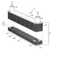
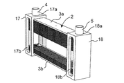
図1は、本実施形態の積層型プレートフィン熱交換器(以下、単に熱交換器と称する)1の外観を示す斜視図である。図1に示すように、本実施形態の熱交換器1は、第1流体である冷媒が給入される給入管(入口ヘッダ)4と、長方形の板状である複数のプレートフィン2aを積層して構成されたプレートフィン積層体2と、プレートフィン2aの中に形成された流路を流れた冷媒を排出する排出管(出口ヘッダ)5とを有している。なお、本実施形態においては、給入管4およぼ排出管5を合わせて給排管と称する。   FIG. 1 is a perspective view showing an appearance of a laminated plate fin heat exchanger (hereinafter simply referred to as a heat exchanger) 1 according to the present embodiment. As shown in FIG. 1, the heat exchanger 1 of the present embodiment is configured by laminating a feed pipe (inlet header) 4 into which a refrigerant as a first fluid is fed and a plurality of plate fins 2 a in the form of a rectangular plate. And a discharge pipe (outlet header) 5 for discharging the refrigerant flowing through the flow path formed in the plate fins 2a. In the present embodiment, the inlet pipe 4 and the outlet pipe 5 are collectively referred to as an inlet and outlet pipe.

また、複数のプレートフィン2aが積層されて構成されたプレートフィン積層体2の積層方向の両端(上下端)には、長方形のプレートフィン2aと平面視が略同一形状のエンドプレート3a、3bが設けられている。エンドプレート3a、3bは、剛性を有する板材で形成されており、例えばアルミニウム、アルミニウム合金、ステンレスなどの金属材を研削により金属加工して形成されている。エンドプレート3a、3bは、積層されたプレートフィン2aを上下から挟むように配設されており、積層されたプレートフィン2aの積層間が所定間隔に確実に保持されるように構成されている。   Further, at both ends (upper and lower ends) of the plate fin laminate 2 formed by laminating a plurality of plate fins 2a in the stacking direction, end plates 3a and 3b having substantially the same shape as the rectangular plate fins 2a It is provided. The end plates 3a and 3b are formed of a rigid plate material, and are formed, for example, by grinding a metal material such as aluminum, an aluminum alloy, or stainless steel. The end plates 3a and 3b are disposed so as to sandwich the stacked plate fins 2a from above and below, and are configured to reliably hold a predetermined interval between the stacked plate fins 2a.

本実施形態においては、プレートフィン積層体2の積層方向が鉛直方向であり、プレートフィン積層体2の上端に配設した上部エンドプレート3aに給排管4、5が設けられた構成である。なお、上部エンドプレート3aにおいては、プレートフィン積層体2の長手方向の両側端部近傍に給入管4と排出管5がそれぞれ設けられている。従って、給入管4から給入された第1流体である冷媒が各プレートフィン2aの内部に形成された複数の流路を水平方向に流れて排出管5から排出される構成である。   In the present embodiment, the stacking direction of the plate fin laminate 2 is the vertical direction, and the upper end plate 3 a disposed at the upper end of the plate fin laminate 2 is provided with the supply / discharge pipes 4, 5. In the upper end plate 3a, the inlet pipe 4 and the discharge pipe 5 are provided in the vicinity of both end portions in the longitudinal direction of the plate fin laminate 2, respectively. Accordingly, the refrigerant, which is the first fluid supplied from the inlet pipe 4, flows horizontally through the plurality of flow paths formed inside the plate fins 2 a and is discharged from the discharge pipe 5.

上記のように構成された本実施形態の熱交換器1においては、第1流体である冷媒がプレートフィン積層体2の各プレートフィン2aの内部の複数の流路を長手方向に並行に流れる構成である。一方、第2流体である空気は、プレートフィン積層体2におけるプレートフィン2aの積層間に形成された隙間を通り抜ける構成である。このように構成された熱交換器1は、プレートフィン積層体2において第1流体と第2流体との熱交換が行われる。   In the heat exchanger 1 of the present embodiment configured as described above, the refrigerant, which is the first fluid, flows in parallel in the longitudinal direction in the plurality of flow paths inside the plate fins 2 a of the plate fin laminate 2. It is. On the other hand, air, which is the second fluid, is configured to pass through the gap formed between the stacks of the plate fins 2 a in the plate fin stack 2. In the heat exchanger 1 configured as described above, heat exchange between the first fluid and the second fluid is performed in the plate fin laminate 2.

本実施形態の熱交換器1におけるプレートフィン積層体2は、二種類の流路構成を有するプレートフィン2a(6、7)が積層されて構成されている。二種類のプレートフィン2aの第1プレートフィン6と第2プレートフィン7は、プレートフィン積層体2において交互に配置されている。   The plate fin laminate 2 in the heat exchanger 1 of the present embodiment is configured by laminating plate fins 2a (6, 7) having two types of flow path configurations. The first plate fins 6 and the second plate fins 7 of the two types of plate fins 2 a are alternately arranged in the plate fin laminate 2.

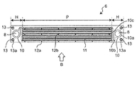
まず、本実施形態の熱交換器1に用いられている第1プレートフィン6について説明する。図2は、第1プレートフィン6を示す平面図である。図2に示すように、第1プレートフィン6は、長手方向の両側に形成されたヘッダ領域Hと、両側のヘッダ領域Hの間に形成された流路領域Pとを有している。   First, the 1st plate fin 6 used for the heat exchanger 1 of this embodiment is demonstrated. FIG. 2 is a plan view showing the first plate fins 6. As shown in FIG. 2, the first plate fin 6 has a header area H formed on both sides in the longitudinal direction and a flow path area P formed between the header areas H on both sides.

第1プレートフィン6の両側に形成されたヘッダ領域Hには、給入管4からの冷媒、または排出管5への冷媒が流れるヘッダ開口8が形成されている。また、ヘッダ領域Hには、ヘッダ開口8からの冷媒、またはヘッダ開口8への冷媒が流れるヘッダ流路10がそれぞれに形成されており、第1プレートフィン6の両側に形成されたそれぞれのヘッダ流路10は対称的な形状を有している。本実施の形態にいては、第1プレートフィン6の両側に配設されたヘッダ流路10は、後述するように、第1プレートフィン6の平面視の中心を対称の中心とした点対称の形状を有する。   In the header area H formed on both sides of the first plate fin 6, a header opening 8 through which the refrigerant from the inlet pipe 4 or the refrigerant to the outlet pipe 5 flows is formed. Further, in the header region H, the header channels 10 through which the refrigerant from the header opening 8 or the refrigerant to the header opening 8 flows are respectively formed, and the respective headers formed on both sides of the first plate fins 6 The flow path 10 has a symmetrical shape. In the present embodiment, the header channels 10 disposed on both sides of the first plate fin 6 are point symmetrical with the center of the plan view of the first plate fin 6 as the center of symmetry as described later. It has a shape.

第1プレートフィン6において、両側のヘッダ領域Hの間に形成された流路領域Pには、給入管4から排出管5に冷媒を流すための複数の冷媒流路(第1流体流路)11が形成されている。複数の冷媒流路11は、長手方向に並行に形成されており、両側にあるヘッダ領域Hのヘッダ流路10と連通している。   A plurality of refrigerant flow paths (first fluid flow paths) for flowing the refrigerant from the inlet pipe 4 to the discharge pipe 5 in the flow path area P formed between the header areas H on both sides in the first plate fin 6 11 are formed. The plurality of refrigerant channels 11 are formed in parallel in the longitudinal direction, and communicate with the header channels 10 of the header region H on both sides.

図2に示すように、両側のヘッダ領域Hにおけるそれぞれの略中央には円形の貫通孔であるヘッダ開口8が形成されており、ヘッダ開口8の周りには冷媒が流れるヘッダ流路10が形成されている。ヘッダ流路10は、ヘッダ開口8の外周において上下に膨出するよう形成された外周流路10aと、この外周流路10aにおける流路領域P側(第1プレートフィン6の中央側)から短手方向に延びる一本の迂回流路10bと、この迂回流路10bを流路領域Pにおける各冷媒流路11に繋ぐ多分岐流路10cと、含む。第1プレートフィン6の両側に設けられたヘッダ流路10は、対称的な形状を有している。例えば、図2に示す左側のヘッダ流路10の迂回流路10bは、その外周流路10aの流路領域P側から短手方向の一方(図2の上方向)に延びており、右側のヘッダ流路10の迂回流路10bは、その外周流路10aの流路領域P側から短手方向の他方(図2の下方向)に延びている。即ち、第1プレートフィン6の両側に設けられたヘッダ流路10は、第1プレートフィン6の平面視における中心を対称の中心とした点対称の形状を有している。   As shown in FIG. 2, a header opening 8 which is a circular through hole is formed substantially at the center of each of the header regions H on both sides, and a header flow passage 10 in which a refrigerant flows is formed around the header opening 8. It is done. The header flow passage 10 is formed from an outer peripheral flow passage 10 a formed to bulge upward and downward around the outer periphery of the header opening 8 and a short from the flow passage region P side (central side of the first plate fin 6) in the outer peripheral flow passage 10 a. It includes a single bypass flow passage 10 b extending in the hand direction, and a multi-branch flow passage 10 c connecting the bypass flow passage 10 b to each refrigerant flow passage 11 in the flow passage region P. The header channels 10 provided on both sides of the first plate fins 6 have a symmetrical shape. For example, the bypass flow passage 10b of the header flow passage 10 on the left side shown in FIG. 2 extends from the flow passage region P side of the outer peripheral flow passage 10a to one in the short direction (upward in FIG. 2) The bypass flow passage 10b of the header flow passage 10 extends from the flow passage region P side of the outer peripheral flow passage 10a to the other side (downward direction in FIG. 2) in the short side direction. That is, the header flow paths 10 provided on both sides of the first plate fin 6 have a point-symmetrical shape with the center of the first plate fin 6 in a plan view as the center of symmetry.

ヘッダ流路10において、第1プレートフィン6の短手方向に延びた迂回流路10bは、流路領域Pにおいて並列している複数の冷媒流路11に対して分岐して連通する多分岐流路10cに繋がっている。迂回流路10bが多分岐流路10cと繋がっている位置は、第1プレートフィン6の短手方向における最も端の冷媒流路11の流路延長上にある。従って、図2に示すように、ヘッダ流路10は、外周流路10aから延びる迂回流路10bと多分岐流路10cとによりU字状に形成されており、迂回流路10bと多分岐流路10cとにより、折り返すように形成されている。即ち、第1プレートフィン6の両側の迂回流路10bと多分岐流路10cは、第1プレートフィン6の平面視における中心を対称の中心とした点対称の形状を有している。このように構成されたヘッダ流路10において、迂回流路10bを通った冷媒が、第1プレートフィン6の短手方向における最も端の冷媒流路11から順次、並設された冷媒流路11に冷媒が送り込まれる。   In the header flow passage 10, the bypass flow passage 10b extending in the short direction of the first plate fins 6 is branched and connected to the plurality of refrigerant flow passages 11 in parallel in the flow passage region P. It is connected to the road 10c. The position where the bypass flow passage 10 b is connected to the multi-branch flow passage 10 c is on the flow passage extension of the refrigerant flow passage 11 at the end in the short direction of the first plate fin 6. Therefore, as shown in FIG. 2, the header flow passage 10 is formed in a U shape by the bypass flow passage 10b extending from the outer peripheral flow passage 10a and the multi-branch flow passage 10c, and the bypass flow passage 10b and the multi-branch flow It is formed to be folded back by the path 10c. That is, the bypass flow passage 10b and the multi-branch flow passage 10c on both sides of the first plate fin 6 have a point symmetrical shape with the center of the first plate fin 6 in a plan view as the center of symmetry. In the header flow passage 10 configured in this manner, the refrigerant flowing through the bypass flow passage 10 b is sequentially arranged in parallel from the refrigerant flow passage 11 at the end in the short direction of the first plate fins 6. The refrigerant is fed to the

図2に示すように、流路領域Pには、冷媒流路11に隣接するように、複数の突起12(第1ダボ:12a、第2ダボ:12b)が所定間隔を有して形成されている。これらの突起12(12a、12b)は、二種類の形状(特に、突出長さが異なる)を有している。第1ダボ12aは、流路領域支持部であり、流路領域Pの縁部(図2においては下側の縁部)に突設されている。第1ダボ12aは、プレートフィン積層体2において積層方向で隣接するプレートフィン2aにおける流路領域Pの縁部と当接するよう構成されている。このように、第1ダボ12aが隣接するプレートフィン2aの流路領域Pの縁部と当接することにより、隣接するプレートフィン2aの積層間の距離が所定の長さに確実に規定される。   As shown in FIG. 2, a plurality of protrusions 12 (first dowels 12 a and second dowels 12 b) are formed at predetermined intervals in the flow passage region P so as to be adjacent to the refrigerant flow passage 11. ing. These protrusions 12 (12a, 12b) have two types of shapes (in particular, the protrusion lengths are different). The first dowel 12 a is a flow path region support portion, and is provided so as to protrude from an edge (lower edge in FIG. 2) of the flow path region P. The first dowels 12 a are configured to be in contact with the edge of the flow passage area P in the plate fins 2 a adjacent in the stacking direction in the plate fin laminate 2. Thus, the distance between the laminations of the adjacent plate fins 2a is surely defined as a predetermined length by the first dowels 12a coming into contact with the edge portion of the flow passage region P of the adjacent plate fins 2a.

第2ダボ12bは、流路支持部であり、流路領域Pにおいて並設された冷媒流路11の流路間に所定間隔を有して配設されている。本実施形態においては、第2ダボ12bが第1ダボ12aと共に第2流体(空気)の流れ方向と沿って並ぶように配設されている。第2ダボ12bは、プレートフィン積層体2において積層方向で隣接するプレートフィン2aにおける冷媒流路11に対向するように配置されており、隣接するプレートフィン2aにおける冷媒流路11の管壁(外壁)に当接する。このように、第2ダボ12bが隣接するプレートフィン2aの冷媒流路11の外壁に当接するため、隣接するプレートフィン2aと冷媒流路11との間の隙間が所定の長さに確実に規定される。   The second dowels 12 b are flow path support portions, and are arranged at predetermined intervals between the flow paths of the refrigerant flow paths 11 arranged in parallel in the flow path region P. In the present embodiment, the second dowels 12 b are arranged along the flow direction of the second fluid (air) together with the first dowels 12 a. The second dowels 12 b are disposed to face the coolant channels 11 in the adjacent plate fins 2 a in the stacking direction in the plate fin laminate 2, and the pipe wall of the coolant channels 11 in the adjacent plate fins 2 a (outer wall Abuts). As described above, since the second dowel 12b abuts on the outer wall of the refrigerant channel 11 of the adjacent plate fin 2a, the gap between the adjacent plate fin 2a and the refrigerant channel 11 is reliably defined to a predetermined length. Be done.

なお、第1ダボ12aと第2ダボ12bは、プレートフィン積層体2の積層間に流れる第2流体(空気:B)の流れ方向に対して千鳥配列に配設してもよく、少なくとも第2ダボ12bが第2流体の流れ方向に対して千鳥配列に配設されていればよい。このように構成することにより、プレートフィン積層体2の積層間に流れる第2流体が乱流となり、流路が確保され、熱伝達率を向上させている。   The first dowels 12 a and the second dowels 12 b may be arranged in a staggered arrangement with respect to the flow direction of the second fluid (air: B) flowing between the laminations of the plate fin laminate 2, The dowels 12b may be arranged in a staggered arrangement in the flow direction of the second fluid. By this configuration, the second fluid flowing between the laminations of the plate fin laminate 2 becomes a turbulent flow, a flow path is secured, and the heat transfer rate is improved.

また、第1プレートフィン6において、各ヘッダ領域Hには位置決め用の貫通孔である位置決め孔13が2つ形成されている。位置決め孔13は、複数のプレートフィン2a(6、7)を積層するときの位置決め孔であり、位置決め孔13に位置決めピンを装着して他のプレートフィン2aとの積層位置が高精度に保持される。なお、位置決めピンとしては、位置決め孔に挿入された状態で固着されてもよく、熱交換器としての剛性を高める構成としてもよい。一方、熱交換器の軽量化などのために最終的に位置決めピンを熱交換器から引き抜く構成としてもよい。   Further, in the first plate fins 6, two positioning holes 13 which are positioning through holes are formed in each header region H. The positioning hole 13 is a positioning hole when laminating a plurality of plate fins 2a (6, 7), and a positioning pin is attached to the positioning hole 13 to hold the stacking position with other plate fins 2a with high accuracy. Ru. In addition, as a positioning pin, it may be fixed in the state inserted in the positioning hole, and it is good also as a structure which improves the rigidity as a heat exchanger. On the other hand, the positioning pins may be finally withdrawn from the heat exchanger in order to reduce the weight of the heat exchanger and the like.

また、位置決め孔13の外周部分には上下に膨出した位置決め外周部13aが形成されている。この位置決め外周部13aは冷媒が流れる流路とは異なる空間を形成している。位置決め外周部13aは、後述するように積層方向に隣接するプレートフィン2a(6、7)の間で当接して、積層方向に隣接するプレートフィン2aの間に所定間隔を保持するヘッダ領域支持機能を有するヘッダ領域支持部となる。   Further, a positioning outer peripheral portion 13 a which bulges up and down is formed on the outer peripheral portion of the positioning hole 13. The positioning outer peripheral portion 13a forms a space different from the flow path through which the refrigerant flows. The positioning outer peripheral portion 13a abuts between the plate fins 2a (6, 7) adjacent in the stacking direction as described later, and holds a predetermined space between the plate fins 2a adjacent in the stacking direction. And a header area support portion.

ヘッダ領域Hに形成されるヘッダ流路10(10a、10b、10c)および位置決め孔13の周りに形成される位置決め外周部13aは、第1プレートフィン6の上面および下面において、所定の高さを有して突出するように形成されている。なお、ヘッダ流路10(10a、10b、10c)および位置決め外周部13aにおける突出面(上端面および下端面)は、平坦面に形成されている。従って、ヘッダ流路10(10a、10b、10c)において流れ方向に直交する縦断面形状は、突出部分(上端部分および下端部分)が平坦な矩形形状を有している。   The header channels 10 (10 a, 10 b, 10 c) formed in the header region H and the positioning outer peripheral portion 13 a formed around the positioning holes 13 have predetermined heights on the upper surface and the lower surface of the first plate fins 6. It is formed to have and project. The projecting surfaces (upper end surface and lower end surface) of the header channel 10 (10a, 10b, 10c) and the positioning outer peripheral portion 13a are formed to be flat surfaces. Therefore, the vertical cross-sectional shape orthogonal to the flow direction in the header flow channel 10 (10a, 10b, 10c) has a flat rectangular shape in which the projecting portions (upper end portion and lower end portion) are flat.

本実施形態においては、ヘッダ流路10および位置決め外周部13aの高さは、プレートフィン積層体2において積層方向で隣接するプレートフィン2a間の隙間(距離)の半分の長さ(1/2ピッチ)に形成されている。このため、積層方向に隣接するプレートフィン2aのヘッダ領域Hにおいては、ヘッダ流路10の管壁(外壁)と位置決め外周部13aが、対向するヘッダ流路10の管壁(外壁)と位置決め外周部13aとにそれぞれ当接する。当接するヘッダ流路10の外壁は平坦な面であるため、例えばロウ付けなどにより確実に固着され得る面となる。従って、プレートフィン積層体2におけるそれぞれのプレートフィン2aのヘッダ領域Hは、予め設定した所定間隔を確実に有して積層された状態となる。   In the present embodiment, the heights of the header channel 10 and the positioning outer peripheral portion 13a are half the length (1/2 pitch) of the gap (distance) between the plate fins 2a adjacent in the stacking direction in the plate fin laminate 2 Is formed. For this reason, in the header region H of the plate fins 2a adjacent in the stacking direction, the pipe wall (outer wall) of the header flow passage 10 and the positioning outer peripheral portion 13a are opposite to the pipe wall (outer wall) of the header flow passage 10 and the positioning outer periphery It abuts on the part 13a respectively. Since the outer wall of the header channel 10 to be in contact is a flat surface, it is a surface that can be securely fixed by, for example, brazing. Therefore, the header region H of each plate fin 2 a in the plate fin laminate 2 is in a state of being stacked with certain predetermined intervals set in advance.

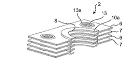
図3は、プレートフィン積層体2における第1プレートフィン6の構成の一部を拡大して示した分解図である。第1プレートフィン6は、アルミニウム、アルミニウム合金、ステンレスなどの金属板で形成されている。なお、プレートフィン積層体2において、第1プレートフィン6と交互に積層される第2プレートフィン7も第1プレートフィン6と同じ材料により形成されている。   FIG. 3 is an exploded view showing a part of the configuration of the first plate fin 6 in the plate fin laminate 2 in an enlarged manner. The first plate fins 6 are formed of a metal plate such as aluminum, an aluminum alloy, or stainless steel. In the plate fin laminate 2, the second plate fins 7 alternately stacked with the first plate fins 6 are also formed of the same material as the first plate fins 6.

図3に示すように、第1プレートフィン6は、芯材に少なくとも一つのロウ材層が形成された板材をプレス加工した第1板状部材6aと、同じ構成の板材をプレス加工した第2板状部材6bとをはり合わせることにより形成されている。第1板状部材6aおよび第2板状部材6bにおいて、ヘッダ領域Hにおけるヘッダ流路10および位置決め孔13の周りに形成される位置決め外周部13a、そして流路領域Pにおける冷媒流路11、突起(第1ダボ12aおよび第2ダボ12b)12は、それぞれが形成される形状にプレス加工される。   As shown in FIG. 3, the first plate fins 6 are formed by pressing a plate material having the same configuration as the first plate member 6a obtained by pressing a plate material having at least one brazing material layer formed on a core material. It is formed by bonding together the plate-like member 6b. In the first plate member 6a and the second plate member 6b, the positioning outer peripheral portion 13a formed around the header flow passage 10 and the positioning hole 13 in the header region H, and the refrigerant flow passage 11 in the flow passage region P, protrusion The (first dowel 12a and the second dowel 12b) 12 is pressed into a shape in which each is formed.

前述のように、ヘッダ領域Hに形成された外周流路10a、迂回流路10bおよび多分岐流路10cで構成されたヘッダ流路10、および位置決め孔13の周りに形成された位置決め外周部13aは、第1プレートフィン6の上面および下面において突出して形成されており、それぞれが積層方向で隣接するプレートフィン2aとの間の距離の半分(1/2ピッチ)の同じ高さを有している。また、ヘッダ流路10における外周流路10a、迂回流路10bおよび多分岐流路10cは、流路領域Pに並設された冷媒流路11に比して幅広に形成されており、流れ方向に直交する縦断面形状が矩形形状を有している。一方、流路領域Pに形成される冷媒流路11においては、水力直径が1mm以下が望ましい。   As described above, the outer peripheral flow passage 10a formed in the header region H, the header flow passage 10 formed of the bypass flow passage 10b and the multi-branch flow passage 10c, and the positioning outer peripheral portion 13a formed around the positioning hole 13 Are formed protruding on the upper and lower surfaces of the first plate fins 6, and each have the same height of half (1/2 pitch) of the distance between the adjacent plate fins 2a in the stacking direction There is. Further, the outer peripheral flow passage 10a, the bypass flow passage 10b, and the multi-branch flow passage 10c in the header flow passage 10 are formed wider than the refrigerant flow passage 11 provided in parallel in the flow passage region P The longitudinal cross-sectional shape orthogonal to the has a rectangular shape. On the other hand, in the refrigerant flow path 11 formed in the flow path region P, the hydraulic diameter is desirably 1 mm or less.

なお、本実施形態においては、冷媒流路11の断面形状(冷媒が流れる方向に直交する断面形状)が円形形状で説明するが、本開示においては円形形状に限定されるものではない。なお、本開示において、円形形状とは、円形、楕円、および閉鎖曲線で形成された複合曲線形状も含むものとする。本開示における冷媒流路11としては、例えば、図4に示すように、冷媒が流れる方向に直交する断面形状が、円形形状の他に、矩形形状などを含み、積層方向の一方側にのみ突出した形状、または積層方向の両側に突出して形成され構成を含む。なお、冷媒流路の各種断面形状を示す図4においては、冷媒流路11が2枚の板状部材で形成されていることを示すために離れた状態で示しているが、実際は2枚の板状部材は当接して所定の断面形状を有する冷媒流路11が形成されている。   In the present embodiment, the cross-sectional shape (the cross-sectional shape orthogonal to the direction in which the refrigerant flows) of the coolant channel 11 is described as a circular shape, but the present disclosure is not limited to the circular shape. In the present disclosure, the circular shape also includes a compound curve shape formed by a circle, an ellipse, and a closed curve. As the coolant channel 11 in the present disclosure, for example, as shown in FIG. 4, the cross-sectional shape orthogonal to the flowing direction of the coolant includes a rectangular shape and the like in addition to a circular shape, and protrudes only on one side in the stacking direction. It includes a configuration having a shape or protruding on both sides in the stacking direction. In addition, in FIG. 4 showing various cross-sectional shapes of the refrigerant flow path, although it is shown in a separated state to show that the refrigerant flow path 11 is formed of two plate-like members, actually it is shown as two The plate-like member abuts and a refrigerant channel 11 having a predetermined cross-sectional shape is formed.

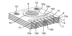
図5は、プレートフィン積層体2における第1プレートフィン6のヘッダ領域Hの近傍を示す平面図である。図6は、図5に示したプレートフィン積層体2をVI−VI線により切断した断面を示す斜視図である。図6のプレートフィン積層体2に示すように、プレートフィン積層体2は第1プレートフィン6と第2プレートフィン7が交互に積層されて構成されている。図6においては、4枚のプレートフィン(6、7)が積層された状態を示しているが、これは一部であり、プレートフィン積層体2においては多数枚のプレートフィン(6、7)が交互に積層される。   FIG. 5 is a plan view showing the vicinity of the header region H of the first plate fin 6 in the plate fin laminate 2. FIG. 6 is a perspective view showing a cross section of the plate fin laminate 2 shown in FIG. 5 taken along line VI-VI. As shown in the plate fin laminate 2 of FIG. 6, the plate fin laminate 2 is configured by alternately laminating first plate fins 6 and second plate fins 7. Although FIG. 6 shows a state in which four plate fins (6, 7) are stacked, this is a part, and in the plate fin laminate 2, a large number of plate fins (6, 7) Are alternately stacked.

プレートフィン積層体2は、第1プレートフィン6と第2プレートフィン7のそれぞれのヘッダ領域Hにおけるヘッダ流路10の外壁(平坦面)が、積層方向で隣接するプレートフィン(6、7)のヘッダ流路10の外壁(平坦面)に積層方向で当接する。図6においては、外周流路10aの外壁の平坦面が、積層方向で隣接するプレートフィン(6、7)の外周流路10aの外壁の平坦面に当接していることが示されている。本実施形態において、ヘッダ流路10を流れる冷媒は、ヘッダ流路10において高い圧力が加えられているが、ヘッダ流路10の管壁(外壁)が隣接するプレートフィン(6、7)のヘッダ流路10の管壁(外壁)に固着されているため、ヘッダ流路10における管壁の膨出が規制されており、耐圧構成となっている。このため、本実施形態の構成においては、ヘッダ流路10に流れる冷媒の圧力を高く設定することが可能となり、効率の高い熱交換を信頼性高く行うことができる。   In the plate fin laminate 2, the outer wall (flat surface) of the header flow passage 10 in the header region H of each of the first plate fins 6 and the second plate fins 7 is the plate fins (6, 7) adjacent in the stacking direction It abuts on the outer wall (flat surface) of the header channel 10 in the stacking direction. In FIG. 6, it is shown that the flat surface of the outer wall of the outer peripheral flow passage 10a is in contact with the flat surface of the outer wall of the outer peripheral flow passage 10a of the adjacent plate fins (6, 7) in the stacking direction. In the present embodiment, a high pressure is applied to the refrigerant flowing through the header flow passage 10 in the header flow passage 10, but the header of the plate fin (6, 7) to which the pipe wall (outer wall) of the header flow passage 10 is adjacent. Because it is fixed to the pipe wall (outer wall) of the flow path 10, the expansion of the pipe wall in the header flow path 10 is restricted, and it has a pressure resistant construction. Therefore, in the configuration of the present embodiment, the pressure of the refrigerant flowing through the header channel 10 can be set high, and highly efficient heat exchange can be performed with high reliability.

なお、ヘッダ領域Hにおけるヘッダ流路10の管壁のみを他の部位より厚みのある厚肉部で形成するように構成してもよい。図7は、厚みの異なる板材をプレス成形により加工したヘッダ領域Hの一部を示した断面図である。図7に示すように、ヘッダ領域Hにおけるヘッダ流路10の管壁部分を他の部分と比して厚みが厚い厚肉部で構成することにより、さらに高い圧力の冷媒に対しても確実に対応することが可能な熱交換器の構成となる。   In addition, you may comprise so that only the tube wall of the header flow path 10 in the header area | region H may be formed by the thick part which is thicker than another site | part. FIG. 7 is a cross-sectional view showing a part of a header area H in which plate members having different thicknesses are processed by press forming. As shown in FIG. 7, by forming the tube wall portion of the header flow passage 10 in the header region H with a thick portion which is thicker than the other portions, it is possible to ensure even the refrigerant of a higher pressure. It becomes the composition of the heat exchanger which can respond.

また、流路領域Pにおける冷媒流路11の管壁のみを、図7に示すように、他の部位より厚みの厚い厚肉部で構成してもよい。このように構成することにより、冷媒流路11において更に高い圧力の冷媒に対応可能な構成となる。   Further, as shown in FIG. 7, only the tube wall of the refrigerant flow passage 11 in the flow passage region P may be constituted by a thick portion thicker than the other portions. With such a configuration, the refrigerant channel 11 can be adapted to a refrigerant having a higher pressure.

図6に示したように、本実施形態のプレートフィン積層体2においては第1プレートフィン6と第2プレートフィン7は交互に積層されている。第2プレートフィン7は、第1プレートフィン6と実質的に同様の構成、形状を有しているが、流路領域Pにおける冷媒流路11と突起12(第1ダボ12a、第2ダボ12b)のそれぞれの形成位置が第1プレートフィン6と異なっている。   As shown in FIG. 6, in the plate fin laminate 2 of the present embodiment, the first plate fins 6 and the second plate fins 7 are alternately stacked. The second plate fins 7 have substantially the same configuration and shape as the first plate fins 6, but the refrigerant channel 11 and the projections 12 (the first dowels 12 a and the second dowels 12 b in the channel region P) ) Are different from the first plate fins 6.

図8は、第1プレートフィン6と第2プレートフィン7が積層されてプレートフィン積層体2が構成されていることを示す図である。図8に示すように、第2プレートフィン7においては、流路領域Pの冷媒流路11が第1プレートフィン6の第2ダボ12bに対向する位置となっている。即ち、第2プレートフィン7の流路領域Pにおける冷媒流路11が、第1プレートフィン6の流路領域Pにおける冷媒流路11の間の位置に対向するよう配置される。第1プレートフィン6と第2プレートフィン7が積層されたプレートフィン積層体2においては、流路支持部である第2ダボ12bが対向する冷媒流路11の管壁(外壁)に確実に当接する構成である。   FIG. 8 is a view showing that the plate fin laminate 2 is configured by laminating the first plate fins 6 and the second plate fins 7. As shown in FIG. 8, in the second plate fin 7, the refrigerant channel 11 of the channel region P is at a position facing the second dowel 12 b of the first plate fin 6. That is, the refrigerant flow passage 11 in the flow passage region P of the second plate fin 7 is disposed to face the position between the refrigerant flow passages 11 in the flow passage region P of the first plate fin 6. In the plate fin laminated body 2 in which the first plate fins 6 and the second plate fins 7 are laminated, the pipe wall (outer wall) of the refrigerant flow path 11 opposed to the second dowel 12b which is the flow path supporting portion is reliably engaged. It is the composition which touches.

本実施形態のプレートフィン積層体2においては、流路領域Pにおける第1流体Aが流れる方向に直交する断面において、交互に積層された第1プレートフィン6と第2プレートフィン7における冷媒流路11が、千鳥配列となるよう構成されている。この千鳥配列の具体的な構成としては、後述する図18参照。   In the plate fin laminate 2 of the present embodiment, the refrigerant flow paths in the first plate fins 6 and the second plate fins 7 alternately stacked in a cross section orthogonal to the flow direction of the first fluid A in the flow path region P. 11 are configured to be in a staggered arrangement. As a specific configuration of this staggered arrangement, refer to FIG. 18 described later.

また、第2プレートフィン7の流路領域Pにおける縁部に形成された流路領域支持部である第1ダボ12aは、隣接する第1プレートフィン6の流路領域Pの縁部に当接して固着される構成である。従って、流路領域支持部である第1ダボ12aの突出高さは、流路支持部である第2ダボ12bの突出高さより、冷媒流路11の高さの分だけ高くなっている。   Further, the first dowels 12 a, which are flow path area supporting portions formed at the edge of the flow path area P of the second plate fins 7, abut on the edge of the flow path area P of the adjacent first plate fins 6. And is fixed. Therefore, the protrusion height of the first dowel 12a, which is the flow passage region support, is higher than the protrusion height of the second dowel 12b, which is the flow passage support, by the height of the refrigerant flow passage 11.

図9は、図8に示したプレートフィン積層体2をIX−IX線により切断した断面を示す斜視図である。図9に示すプレートフィン積層体2においては、上から順に第1プレートフィン6、第2プレートフィン7、第1プレートフィン6、および第2プレートフィン7の4枚のみを積層した状態を示している。図9に示すように、第1プレートフィン6における流路領域Pの第1ダボ12aは、対向する第2プレートフィン7における流路領域Pの縁部に当接している。また、第2プレートフィン7における流路領域Pの第1ダボ12aは、対向する第1プレートフィン6における流路領域Pの縁部に当接している。   FIG. 9 is a perspective view showing a cross section of the plate fin laminate 2 shown in FIG. 8 taken along line IX-IX. In the plate fin laminate 2 shown in FIG. 9, only the four first plate fins 6, the second plate fins 7, the first plate fins 6, and the second plate fins 7 are stacked in order from the top. There is. As shown in FIG. 9, the first dowel 12 a of the flow passage area P in the first plate fin 6 abuts on the edge of the flow passage area P in the opposing second plate fin 7. Further, the first dowels 12 a of the flow passage area P in the second plate fins 7 are in contact with the edge of the flow passage area P in the opposing first plate fins 6.

一方、第1プレートフィン6における流路領域Pの第2ダボ12bは、対向する第2プレートフィン7における流路領域Pの冷媒流路11の管壁(外壁)に当接している。また、第2プレートフィン7における流路領域Pの第2ダボ12bは、対向する第1プレートフィン6における流路領域Pの冷媒流路11の管壁(外壁)に当接している。   On the other hand, the second dowel 12 b of the flow passage area P in the first plate fin 6 abuts on the pipe wall (outer wall) of the refrigerant flow path 11 of the flow passage area P in the opposing second plate fin 7. Further, the second dowels 12 b of the flow passage region P in the second plate fin 7 are in contact with the pipe wall (outer wall) of the refrigerant flow passage 11 of the flow passage region P in the opposing first plate fin 6.

なお、本開示においては、プレートフィン積層体2における積層されたプレートフィン2a(6、7)はロウ付けにより固着される構成で説明するが、本開示はこの構成に限定されるものではなく、他の耐熱性のある固定方法、例えば機械的な接続方法、化学的な接合部材を用いた固着方法を用いてもよい。   In the present disclosure, the stacked plate fins 2a (6, 7) in the plate fin laminate 2 are described as being fixed by brazing, but the present disclosure is not limited to this configuration, Other heat-resistant fixing methods, such as a mechanical connection method and a fixing method using a chemical bonding member may be used.

上記のように、本実施形態のプレートフィン積層体2においては、流路領域Pの第1ダボ12aが対向するフィンプレート(6、7)の流路領域Pの縁部を確実に支持し、積層間に所定の隙間が確保される。本実施形態においては、流路領域Pの第1ダボ12aがプレートフィン積層体2における流路領域支持部となる。   As described above, in the plate fin laminate 2 of the present embodiment, the edge of the flow path area P of the fin plate (6, 7) opposed to the first dowel 12a of the flow path area P is reliably supported, A predetermined gap is secured between the laminations. In the present embodiment, the first dowel 12 a of the flow passage region P serves as the flow passage region supporting portion in the plate fin laminate 2.

また、流路領域Pの第2ダボ12bが対向するフィンプレート(6、7)の冷媒流路11の管壁(外壁)に当接する構成であり、この点においてもプレートフィン積層体2におけるフィンプレート(6、7)と冷媒流路11との積層間に所定の間隔が保持される構成となる。本実施形態においては、流路領域Pの第2ダボ12bがプレートフィン積層体2における流路支持部となる。   In addition, the second dowels 12b of the flow passage region P are in contact with the pipe wall (outer wall) of the refrigerant flow passage 11 of the facing fin plate (6, 7). A predetermined distance is maintained between the stacks of the plates (6, 7) and the coolant channel 11. In the present embodiment, the second dowels 12 b of the flow passage region P serve as the flow passage supporting portion in the plate fin laminate 2.

なお、上記の実施形態においては、流路領域Pの第1ダボ12aが対向するフィンプレート(6、7)の流路領域Pの縁部に当接する構成で述べたが別の構成でも対応可能である。例えば、流路領域Pの縁部に形成される流路領域支持部である第1ダボ12aを、流路領域凸部とし、対向するフィンプレート(6、7)の流路領域Pの縁部に流路領域凹部を形成して、流路領域凸部と流路領域凹部が嵌合するように構成してもよい。   In the above embodiment, the first dowels 12a of the flow passage region P are described as being in contact with the edge of the flow passage region P of the facing fin plates (6, 7), but other configurations are also possible It is. For example, the first dowel 12a, which is a flow path area support portion formed at the edge of the flow path area P, is used as a flow path area convex portion, and the edge of the flow path area P of the opposing fin plate (6, 7) The flow path region concave portion may be formed to fit the flow path region convex portion and the flow path region concave portion.

[位置決めピンによる積層]
本実施形態のプレートフィン積層体2においては、複数のプレートフィン2a(6、7)が所定位置に容易に、且つ確実に積層できるように、位置決めピン9が装着されるように構成されている。図10は、プレートフィン積層体2に位置決めピン9が装着された状態を示す斜視図である。図11は、位置決めピン9が装着されたプレートフィン積層体2を拡大して示した断面図である。図11の断面図は図10における符号XIで示した面で切断した図である。
[Stacking by positioning pin]
In the plate fin laminate 2 of the present embodiment, the positioning pin 9 is mounted so that the plurality of plate fins 2a (6, 7) can be easily and reliably stacked at a predetermined position. . FIG. 10 is a perspective view showing a state in which the positioning pin 9 is attached to the plate fin laminate 2. FIG. 11 is an enlarged cross-sectional view of the plate fin laminate 2 to which the positioning pin 9 is attached. The cross-sectional view of FIG. 11 is a view cut along a plane indicated by reference numeral XI in FIG.

本実施形態においては、位置決めピン9がそれぞれのプレートフィン2a(6、7)のヘッダ領域Hに形成された貫通孔である位置決め孔13に挿入されてロウ付けされる構成である。このため、プレートフィン積層体2は機械的構造が強化されると共に、冷媒に対する耐圧強度が格段に強化された構成となる。なお、本実施形態においては、位置決めピン9としてアルミニウム金属棒が用いられている。   In the present embodiment, the positioning pin 9 is inserted into the positioning hole 13 which is a through hole formed in the header region H of each plate fin 2a (6, 7) and brazed. For this reason, the plate fin laminate 2 has a mechanical structure reinforced and has a configuration in which the pressure resistance to the refrigerant is remarkably strengthened. In the present embodiment, an aluminum metal rod is used as the positioning pin 9.

本実施形態においては、図2に示したように、流路領域Pに形成された流路領域支持部である第1ダボ12aおよび流路支持部である第2ダボ12bが、第2流体Bである空気の流れ方向と平行に並んで配置されている。このように、積層間において複数の突起が並んで配設されているため、プレートフィン積層体2における積層間に流れる第2流体(空気)Bに対する流路抵抗を少なくすることができる。このように構成することにより、本実施形態のプレートフィン積層体2においては、第2流体が積層間に流れるときに生じる音を低減することが可能となる。   In the present embodiment, as shown in FIG. 2, the first dowel 12 a which is a flow passage area support formed in the flow passage area P and the second dowel 12 b which is a flow passage support are the second fluid B. Are arranged parallel to the air flow direction. As described above, since the plurality of projections are arranged side by side between the laminations, the flow path resistance to the second fluid (air) B flowing between the laminations in the plate fin laminated body 2 can be reduced. With such a configuration, in the plate fin laminate 2 of the present embodiment, it is possible to reduce the sound generated when the second fluid flows between the laminates.

[プレートフィンの変形例]
なお、本開示に係る熱交換器のプレートフィン積層体2におけるプレートフィン2aの変形例としては、突起12(12a、12b)の配置を変更した構成がある。例えば、プレートフィン積層体2における積層間に設けられる複数の突起12(12a、12b)を千鳥配列に配置することにより、積層間を通る第2流体Bにおいて乱流を発生させて、熱交換効率を高める構成としてもよい。図12は、プレートフィン積層体2における積層間に複数の突起12(12a、12b)を千鳥配列に配設した構成を示したプレートフィン2bの平面図である。この構成においても、流路領域支持部である第1ダボ12aは、対向する流路領域Pの縁部に当接し、流路支持部である第2ダボ12bは、対向する流路領域Pの冷媒流路11の管壁(外壁)に当接するよう構成されている。
[Modification of plate fin]
In addition, as a modification of the plate fin 2a in the plate fin laminated body 2 of the heat exchanger which concerns on this indication, there exists a structure which changed arrangement | positioning of protrusion 12 (12a, 12b). For example, by arranging the plurality of protrusions 12 (12a, 12b) provided between the stacks in the plate fin stack 2 in a staggered arrangement, turbulent flow is generated in the second fluid B passing between the stacks, and heat exchange efficiency is achieved. May be configured to enhance the FIG. 12 is a plan view of plate fins 2b showing a configuration in which a plurality of protrusions 12 (12a, 12b) are arranged in a staggered arrangement between the layers in the plate fin laminate 2. As shown in FIG. Also in this configuration, the first dowel 12a, which is the flow passage area support, is in contact with the edge of the opposing flow passage area P, and the second dowel 12b, which is the flow passage support, is in the opposite flow passage area P. It is configured to be in contact with the tube wall (outer wall) of the coolant channel 11.

また、積層間における複数の突起12を風上側より風下側を多く形成することにより、積層間を通る第2流体Bにおいて乱流を発生させて、熱交換効率を高める構成としてもよい。なお、少なくとも、突起12における第1ダボ12aの数が、第2流体B(空気)の流れ方向において、風下側が風上側より多くの突起12を有する構成であればよい。このように風下側の突起12を風上側より多く設けることにより、流速が遅くなる風下側における熱伝達率を高めることが可能となる。図13は、第2流体Bである空気の流れ方向において、風下側の突起12が風上側の突起12より多く設けた構成を示したプレートフィン2cの平面図である。この構成においても、流路領域支持部である第1ダボ12aは、対向する流路領域Pの縁部に当接し、流路支持部である第2ダボ12bは、対向する流路領域Pの冷媒流路の管壁(外壁)に当接する。   Further, by forming the plurality of projections 12 between the laminations more leeward than the windward side, turbulent flow may be generated in the second fluid B passing between the laminations to enhance the heat exchange efficiency. In addition, the number of the first dowels 12 a in the protrusions 12 may be at least the number of the protrusions 12 on the downwind side more than the upwind side in the flow direction of the second fluid B (air). Thus, by providing the projections 12 on the downwind side more than the upwind side, it is possible to increase the heat transfer coefficient on the downwind side where the flow velocity is low. FIG. 13 is a plan view of the plate fin 2c showing a configuration in which the protuberance 12 on the downwind side is provided more than the protuberance 12 on the upwind side in the flow direction of the air that is the second fluid B. Also in this configuration, the first dowel 12a, which is the flow passage area support, is in contact with the edge of the opposing flow passage area P, and the second dowel 12b, which is the flow passage support, is in the opposite flow passage area P. Contact the tube wall (outer wall) of the coolant channel.

上記のように、本実施形態におけるプレートフィン積層体2の積層間に設ける複数の突起12の配置構成に関しては、各種の構成を提示することができるが、熱交換器の仕様、構成、および使用者の要望に応じて最適な構成が選択される。   As described above, regarding the arrangement configuration of the plurality of projections 12 provided between the laminations of the plate fin laminate 2 in the present embodiment, various configurations can be presented, but the specification, configuration, and use of the heat exchanger The optimal configuration is selected according to the needs of the person.

また、熱交換器1におけるプレートフィン積層体2の更なる変形例について説明する。前述の実施形態におけるプレートフィン積層体2においては、長手方向の両側端部近傍に給入管4と排出管5がそれぞれ接続される構成であり、それぞれのプレートフィン2aの両側にヘッダ領域Hが形成されて2つのヘッダ開口8が設けられた構成である(図2参照)。   Moreover, the further modification of the plate fin laminated body 2 in the heat exchanger 1 is demonstrated. In the plate fin laminate 2 in the above-described embodiment, the inlet pipe 4 and the discharge pipe 5 are respectively connected in the vicinity of both end portions in the longitudinal direction, and the header region H is formed on both sides of each plate fin 2a. And two header openings 8 are provided (see FIG. 2).

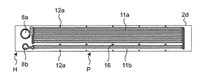
図14は、プレートフィン積層体の変形例を示す図であり、プレートフィン積層体を構成するプレートフィン2dを示す平面図である。図14に示すように、プレートフィン2dにおける一方の端部側(図14においては左側)のみにヘッダ領域Hが形成されており、その他の領域が流路領域Pとなっている。即ち、この変形例のプレートフィン積層体においては、長手方向の一方の端部近傍の領域に給入管と排出管が接続される構成である。図14に示すプレートフィン2dにおいて、左側に示すヘッダ領域Hに給入側のヘッダ開口8aと、排出側のヘッダ開口8bの両方が形成される。   FIG. 14 is a view showing a modification of the plate fin laminate, and is a plan view showing the plate fins 2 d constituting the plate fin laminate. As shown in FIG. 14, the header region H is formed only on one end side (left side in FIG. 14) of the plate fin 2 d, and the other region is the flow passage region P. That is, in the plate fin laminate of this modification, the inlet pipe and the discharge pipe are connected in the region near one end in the longitudinal direction. In the plate fin 2d shown in FIG. 14, both the inlet side header opening 8a and the outlet side header opening 8b are formed in the header area H shown on the left side.

図14のプレートフィン2dにおいては、給入側のヘッダ開口8aの開口形状が排出側のヘッダ開口8bの開口形状より大きな直径を有している。これは、当該熱交換器が凝縮器として使用される場合であるが、その場合、熱交換された後の冷媒の体積が小さくなるためである。また、給入側のヘッダ開口8aからの冷媒は、流路領域Pにおいて並設された複数の冷媒流路11aを流れ、プレートフィン2dにおける端部近傍(図14における右側端部近傍)において折り返す構成である。流路領域Pにおいては、給入側のヘッダ開口8aからの冷媒が流れ込む冷媒流路11aと、端部近傍において折り返した後に冷媒が流れる、排出側のヘッダ開口8bへ流れる冷媒流路11bとが形成されている。なお、当該熱交換器が蒸発器として使用される場合は出入り口は上記の逆となる。   In the plate fin 2d of FIG. 14, the opening shape of the header opening 8a on the supply side has a larger diameter than the opening shape of the header opening 8b on the discharge side. This is the case where the heat exchanger is used as a condenser, in which case the volume of refrigerant after heat exchange is reduced. Further, the refrigerant from the header opening 8a on the inlet side flows through the plurality of refrigerant channels 11a arranged in parallel in the channel area P, and is turned back in the vicinity of the end of the plate fin 2d (near the right end in FIG. 14) It is a structure. In the flow path region P, a refrigerant flow path 11a into which the refrigerant flows from the inlet opening 8a on the inlet side, and a refrigerant flow path 11b flowing to the outlet opening 8b on the discharge side after the return It is formed. In addition, when the said heat exchanger is used as an evaporator, an inlet / outlet becomes reverse of the above-mentioned.

また、図14に示すように、排出側のヘッダ開口8bへ流れる並設された冷媒流路11bの本数は、給入側のヘッダ開口8aからの冷媒が流れ込む並設された冷媒流路11aの本数より少なく設定されている。これは、ヘッダ開口8a、8bの直径が異なることと同じ理由であり、熱交換された後の冷媒の体積が小さくなるためである。   Further, as shown in FIG. 14, the number of the refrigerant channels 11b arranged in parallel to the header opening 8b on the discharge side is the same as that of the refrigerant channels 11a arranged in parallel, into which the refrigerant from the header opening 8a on the inlet side flows. It is set smaller than the number. This is the same reason as the different diameters of the header openings 8a and 8b, and the volume of the refrigerant after heat exchange is reduced.

また、図14に示す構成のプレートフィン2dにおいては、給入側のヘッダ開口8aからの冷媒が流れ込む冷媒流路11aが形成された領域と、排出側のヘッダ開口8bへ流れる冷媒流路11bが形成された領域との間には、プレートフィン内における冷媒同士の熱伝導を低減する目的(断熱)で複数の開口16が形成されている。   Further, in the plate fin 2d having the configuration shown in FIG. 14, the region where the refrigerant passage 11a into which the refrigerant from the header opening 8a on the inlet side flows in is formed, and the refrigerant passage 11b flowing to the header opening 8b on the outlet side Between the formed region, a plurality of openings 16 are formed for the purpose of reducing the heat conduction between the refrigerants in the plate fins (insulation).

[エンドプレート]
次に、本実施の形態の熱交換器1におけるプレートフィン積層体2の積層方向の両端(上下端)に設けられたエンドプレート(3a、3b)について説明する。図15はプレートフィン積層体2の積層方向の上端に設けられた上部エンドプレート3aを示す斜視図であり、図16はプレートフィン積層体2の積層方向の下端に設けられた下部エンドプレート3bを示す斜視図である。図17は、プレートフィン積層体2におけるヘッダ領域Hと上部エンドプレート3aとの接合状態を示す拡大斜視図である。
[end plate]
Next, the end plates (3a, 3b) provided at both ends (upper and lower ends) of the plate fin laminate 2 in the stacking direction in the heat exchanger 1 of the present embodiment will be described. FIG. 15 is a perspective view showing the upper end plate 3a provided on the upper end of the plate fin laminate 2 in the stacking direction, and FIG. 16 is a lower end plate 3b provided on the lower end of the plate fin laminate 2 in the stacking direction. It is a perspective view shown. FIG. 17 is an enlarged perspective view showing a joined state of the header region H and the upper end plate 3 a in the plate fin laminate 2.

本実施の形態においては、前述したように、プレートフィン積層体2を構成する第1プレートフィン6および第2プレートフィン7は、それぞれが2枚の板状部材(6aと6b、7aと7b)をはり合わせて形成されている。即ち、第1プレートフィン6は、プレス加工された第1板状部材6aと第2板状部材6bとをはり合わせて形成されており、第2プレートフィン7は、プレス加工された第1板状部材7aと第2板状部材7bとをはり合わせて形成されている。   In the present embodiment, as described above, the first plate fins 6 and the second plate fins 7 constituting the plate fin laminate 2 are each two plate members (6a and 6b, 7a and 7b) It is formed by bonding together. That is, the first plate fin 6 is formed by bonding the pressed first plate member 6a and the second plate member 6b, and the second plate fin 7 is formed by pressing the first plate 6 The second member 7a and the second plate member 7b are bonded to each other.

本実施形態におけるプレートフィン積層体2は、第1プレートフィン6および第2プレートフィン7が交互に積層されており、プレートフィン積層体2の最上端部には第1プレートフィン6の片側である第2板状部材6bのみが配設されている(図17参照)。従って、プレートフィン積層体2の最上端面は、流路形成のための細い溝である凹みを有するが、この最上端面の多くが平坦面で構成されている。このため、プレートフィン積層体2の最上端面における平坦面が上部エンドプレート3aの下面との接触面である接合面(ロウ付け面)となり、接合面積が大きくなる。   In the plate fin laminate 2 in the present embodiment, the first plate fins 6 and the second plate fins 7 are alternately stacked, and the uppermost end of the plate fin laminate 2 is one side of the first plate fins 6. Only the second plate member 6b is disposed (see FIG. 17). Therefore, although the uppermost end surface of the plate fin laminate 2 has a recess which is a thin groove for forming a flow passage, most of the uppermost end surface is formed of a flat surface. For this reason, the flat surface at the top end face of the plate fin laminate 2 becomes a bonding surface (braided surface) which is a contact surface with the lower surface of the upper end plate 3a, and the bonding area becomes large.

図17に示すように、プレートフィン積層体2の最上端面上に配設される上部エンドプレート3aにおけるプレートフィン積層体2に対向する面にはエンドプレート凸部30が形成されている。このエンドプレート凸部30は、対向する第2板状部材6bにおける流路形成のための凹みに対応する形状を有している。このため、上部エンドプレート3aがプレートフィン積層体2の最上面上に配設されたとき、上部エンドプレート3aのエンドプレート凸部30が第2板状部材6bにおける流路形成のための凹みに嵌まり込む。   As shown in FIG. 17, an end plate convex portion 30 is formed on the surface of the upper end plate 3 a disposed on the uppermost end surface of the plate fin laminate 2 opposite to the plate fin laminate 2. The end plate convex portion 30 has a shape corresponding to a recess for forming a flow path in the facing second plate-like member 6 b. Therefore, when the upper end plate 3a is disposed on the uppermost surface of the plate fin laminate 2, the end plate convex portion 30 of the upper end plate 3a is a recess for forming a flow path in the second plate member 6b. Get stuck.

なお、上部エンドプレート3aに形成されるエンドプレート凸部30としてはヘッダ領域Hにおける幅広の流路形成のための凹部のみに形成されていてもよい。これは、流路領域Pにおける流路形成のための凹部(溝)は幅が狭く十分な当接面が確保されるためである。本実施形態においては、具体例として、プレートフィン積層体2の最上面として第1プレートフィン6の第2板状部材6bが配設された例で説明するが、これは一例であり、プレートフィン積層体2の最上面は、積層順に応じて第1プレートフィン6または第2プレートフィン7におけるいずれかの片側で構成されていればよい。   In addition, as the end plate convex part 30 formed in the upper end plate 3a, it may be formed only in the recessed part for flow path formation of the wide in the header area | region H. As shown in FIG. This is because the recess (groove) for forming the flow passage in the flow passage region P has a narrow width and a sufficient contact surface is secured. In the present embodiment, as a specific example, an example in which the second plate member 6b of the first plate fin 6 is disposed as the uppermost surface of the plate fin laminate 2 will be described, but this is an example. The uppermost surface of the laminated body 2 may be configured by one side of either the first plate fin 6 or the second plate fin 7 according to the order of lamination.

図18は、プレートフィン積層体2の最下端面と下部エンドプレート3bとの接合状態を示す拡大斜視図である。図18に示すように、本実施形態においては、プレートフィン積層体2の最下端部には第2プレートフィン7の片側である第1板状部材7aのみが配設されている。従って、プレートフィン積層体2の最下端面は、流路形成のための凹みを有するが、この最下端面における大部分が平坦面で構成されている。従って、プレートフィン積層体2の最下端面と下部エンドプレート3bとの間には十分な接合面積が確保される。   FIG. 18 is an enlarged perspective view showing a joined state of the lower end surface of the plate fin laminate 2 and the lower end plate 3b. As shown in FIG. 18, in the present embodiment, only the first plate-like member 7 a which is one side of the second plate fins 7 is disposed at the lowermost end of the plate fin laminate 2. Therefore, the lowermost end face of the plate fin laminate 2 has a recess for channel formation, but most of the lowermost end face is formed of a flat surface. Therefore, a sufficient bonding area is secured between the lower end surface of the plate fin laminate 2 and the lower end plate 3b.

[プレートフィン積層体およびエンドプレートの変形例]
図19から図25は、プレートフィン積層体とエンドプレートの各種変形例を示す図である。
[Modification of plate fin laminate and end plate]
FIGS. 19-25 is a figure which shows the various modification of a plate fin laminated body and an end plate.

図19は、プレートフィン積層体2の最下端面と下部エンドプレート31bとの接合状態を示す拡大斜視図である。図19に示すように、プレートフィン積層体2の最下端には第2プレートフィン7の片側である第1板状部材7aが配設されている。プレートフィン積層体2の最下端面は、第1板状部材7aにおいて第1流体流路である冷媒流路11の上半分を構成する第1流体流路用凹部11aの下向きの凹面を有する面により構成されている。第1流体流路用凹部11aの凹面(溝)を有する面が下向きとなり下部エンドプレート31bの上面と接触している。   FIG. 19 is an enlarged perspective view showing a bonded state of the lower end surface of the plate fin laminate 2 and the lower end plate 31 b. As shown in FIG. 19, at the lowermost end of the plate fin laminate 2, a first plate member 7 a which is one side of the second plate fins 7 is disposed. The lowermost end surface of the plate fin laminate 2 is a surface having a downward concave surface of the first fluid channel recess 11a constituting the upper half of the refrigerant channel 11 which is the first fluid channel in the first plate member 7a. It is composed of The surface having the concave surface (groove) of the first fluid channel recess 11a is directed downward and is in contact with the upper surface of the lower end plate 31b.

図20は、下部エンドプレート31bの上面を示す平面図である。図19および図20に示すように、下部エンドプレート31bの上面には、当該下部エンドプレート31bに対向する第1板状部材7aと同じ構成の流路領域Pおよびヘッダ領域Hとを有する。即ち、下部エンドプレート31bの長手方向の両側にヘッダ領域Hが形成され、ヘッダ領域Hに挟まれた中央部分に流路領域Pが形成されている。   FIG. 20 is a plan view showing the upper surface of the lower end plate 31 b. As shown in FIGS. 19 and 20, on the upper surface of the lower end plate 31b, there are provided a flow passage area P and a header area H having the same configuration as the first plate-like member 7a facing the lower end plate 31b. That is, the header area H is formed on both sides in the longitudinal direction of the lower end plate 31 b, and the flow path area P is formed in the central portion sandwiched by the header area H.

図20に示すように、下部エンドプレート31bの上面におけるヘッダ領域Hにはヘッダ流路用凹部32が形成され、流路領域Pには直線状の複数の冷媒流路用凹部(溝)33が並行に形成されている。なお、下部エンドプレート31bにおけるヘッダ領域Hのヘッダ流路用凹部32は、プレートフィン(6、7)におけるヘッダ開口8の円形と実質的に同じ円形を有する有底凹部で構成されている。このヘッダ流路用凹部32は給排管と連通したヘッダ開口8の冷媒を堰き止めている。   As shown in FIG. 20, a header channel recess 32 is formed in the header region H on the upper surface of the lower end plate 31b, and a plurality of linear coolant channel recesses (grooves) 33 are formed in the channel region P. It is formed in parallel. In addition, the recessed part 32 for header flow paths of the header area H in the lower end plate 31b is comprised by the bottomed recessed part which has a circle substantially the same as the circle of the header opening 8 in plate fin (6, 7). The header channel recess 32 blocks the refrigerant at the header opening 8 in communication with the supply and discharge pipe.

上記のように、下部エンドプレート31bに形成された流路領域Pの冷媒流路用凹部(溝)33は、対向する第2プレートフィン7の片側である第1板状部材7aに形成された冷媒流路用凹部11aと同じ位置に同じ形状を有している。そのため、下部エンドプレート31bは、当該下部エンドプレート31bと対向する第1板状部材7aにより、ヘッダ領域Hには冷媒溜まりとなるヘッダ流路が形成され、流路領域Pにはプレートフィン積層体2における冷媒流路11と同じ冷媒流路が形成される。その結果、このように構成された熱交換器においては、下部エンドプレート31bと最下端の第1板状部材7aとにより冷媒流路が形成され、熱交換効率を更に高めることが可能な構成となる。   As described above, the refrigerant channel recesses (grooves) 33 in the channel region P formed in the lower end plate 31 b are formed in the first plate member 7 a which is one side of the opposing second plate fins 7. It has the same shape at the same position as the refrigerant channel recess 11a. Therefore, in the lower end plate 31b, a header flow passage serving as a refrigerant reservoir is formed in the header region H by the first plate-like member 7a facing the lower end plate 31b, and a plate fin laminate is formed in the flow passage region P. The same refrigerant flow path as the refrigerant flow path 11 in 2 is formed. As a result, in the heat exchanger configured as described above, a refrigerant flow path is formed by the lower end plate 31b and the lowermost first plate member 7a, and the heat exchange efficiency can be further enhanced. Become.

なお、図19および図20に示したプレートフィン積層体2の最下端面と下部エンドプレート31bの構成に関しては、プレートフィン積層体2の最上端面と上部エンドプレートの下面においても同様に構成して、プレートフィン積層体2の最上端面と上部エンドプレートの下面との間に冷媒流路を形成することが可能となる。   With regard to the configurations of the lower end surface and the lower end plate 31b of the plate fin laminate 2 shown in FIGS. 19 and 20, the upper surface of the plate fin laminate 2 and the lower surface of the upper end plate are similarly configured. Thus, it is possible to form a refrigerant flow path between the uppermost end surface of the plate fin laminate 2 and the lower surface of the upper end plate.

図21および図22は、さらに別の構成のプレートフィン積層体21と下部エンドプレート34bを示す図である。図21は、プレートフィン積層体21の最下端と下部エンドプレート34bとの接合状態を示す拡大斜視図である。図22は、下部エンドプレート34bの上面を示す平面図(a)と側面図(b)である。図21に示す構成においては、プレートフィン積層体21の最下端には第2プレートフィン7が配設されている。即ち、この変形例においては、プレートフィン積層体21は、2つの板状部材(6aと6b、7aと7b)が張り合わされて構成された第1プレートフィン6と第2プレートフィン7が交互に積層されて構成されている。従って、本変形例においては、プレートフィン積層体21の最下端には、積層順に応じて第1プレートフィン6または第2プレートフィン7のいずれかが配設される構成となる。   FIGS. 21 and 22 are views showing still another configuration of the plate fin laminate 21 and the lower end plate 34 b. FIG. 21 is an enlarged perspective view showing a joined state of the lower end of the plate fin laminate 21 and the lower end plate 34 b. FIG. 22 is a plan view (a) and a side view (b) showing the upper surface of the lower end plate 34b. In the configuration shown in FIG. 21, the second plate fins 7 are disposed at the lowermost end of the plate fin laminate 21. That is, in this modification, in the plate fin laminate 21, the first plate fins 6 and the second plate fins 7 formed by laminating two plate members (6a and 6b, 7a and 7b) are alternately arranged. It is laminated and constituted. Therefore, in the present modification, at the lowermost end of the plate fin laminate 21, either the first plate fin 6 or the second plate fin 7 is disposed in accordance with the stacking order.

図22に示すように、下部エンドプレート34bの上面には、複数の突起(35、36)が形成されており、プレートフィン積層体21の最下端にある、例えば第2プレートフィン7を支持するように構成されている。下部エンドプレート34bの上面に形成された複数の突起(35、36)においては、第2プレートフィン7の冷媒流路11を支持する流路支持用凸部35と、第2プレートフィン7の流路領域Pを支持する流路領域支持用凸部36とに分かれる。図21に示すように、流路支持用凸部35と流路領域支持用凸部36は、二種類の形状(特に、突出長さが異なる)を有している。   As shown in FIG. 22, a plurality of projections (35, 36) are formed on the upper surface of the lower end plate 34b, and for example, supports the second plate fins 7 at the lowermost end of the plate fin laminate 21. Is configured as. In the plurality of projections (35, 36) formed on the upper surface of the lower end plate 34 b, the flow path supporting convex portion 35 for supporting the refrigerant flow path 11 of the second plate fin 7 and the flow of the second plate fin 7 It divides into the flow-path area | region support convex part 36 which supports the channel | path area | region P. FIG. As shown in FIG. 21, the flow path support convex portion 35 and the flow path region support convex portion 36 have two types of shapes (in particular, the projection lengths are different).

下部エンドプレート34bの流路領域支持用凸部36は、第2プレートフィン7における流路領域Pの縁部と当接するよう構成されている。このように、流路領域支持用凸部36が第2プレートフィン7の流路領域Pの縁部と当接することにより、下部エンドプレート34bと第2プレートフィン7との間の距離が所定の長さに確実に規定される。   The flow path region supporting convex portion 36 of the lower end plate 34 b is configured to abut on the edge portion of the flow path region P in the second plate fin 7. Thus, the distance between the lower end plate 34 b and the second plate fin 7 is predetermined by the abutment of the flow path region supporting convex portion 36 with the edge of the flow path region P of the second plate fin 7. The length is definitely defined.

流路支持用凸部35は、流路支持部であり、対向する第2プレートフィン7の流路領域Pにおいて並設された冷媒流路11の位置に配設されている。本変形例においては、流路支持用凸部35が流路領域支持用凸部36と共に第2流体(空気)の流れ方向に沿って並ぶように配設されている。流路支持用凸部35は、冷媒流路11に対向するように配置されており、第2プレートフィン7の冷媒流路11の管壁(外壁)に当接する。このように、流路支持用凸部35が第2プレートフィン7の冷媒流路11の管壁(外壁)に当接するため、下部エンドプレート34bの上面と最下端にある第2プレートフィン7との間の隙間が所定の長さに確実に規定される。   The flow path support convex portion 35 is a flow path support portion, and is disposed at the position of the refrigerant flow path 11 arranged in parallel in the flow path region P of the facing second plate fins 7. In the present modification, the flow path support convex portions 35 are arranged along the flow direction of the second fluid (air) together with the flow path region support convex portions 36. The flow path supporting convex portion 35 is disposed to face the refrigerant flow path 11, and abuts on the pipe wall (outer wall) of the refrigerant flow path 11 of the second plate fin 7. As described above, since the flow path supporting convex portion 35 abuts on the pipe wall (outer wall) of the refrigerant flow path 11 of the second plate fin 7, the second plate fin 7 at the upper surface and the lowermost end of the lower end plate 34b The gap between the two is reliably defined to a predetermined length.

なお、下部エンドプレート34bの上面に形成された複数の突起(35、36)は、プレートフィン積層体21に流れる第2流体(空気:B)の流れ方向に対して千鳥配列に配設してもよい。また、複数の突起(35、36)は、風上側より風下側を多く形成してもよい。   The plurality of projections (35, 36) formed on the upper surface of the lower end plate 34b are disposed in a staggered arrangement in the flow direction of the second fluid (air: B) flowing to the plate fin laminate 21. It is also good. In addition, the plurality of projections (35, 36) may be formed with the leeward side more than the windward side.

なお、図21および図22に示したプレートフィン積層体21の最下端面と下部エンドプレート34bの構成に関しては、プレートフィン積層体21の最上端面と上部エンドプレートの下面においても同様に構成することが可能となる。   With regard to the configurations of the lower end surface and the lower end plate 34b of the plate fin laminate 21 shown in FIGS. 21 and 22, the same should be applied to the uppermost end surface of the plate fin laminate 21 and the lower surface of the upper end plate. Is possible.

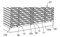
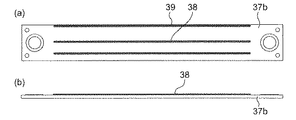
図23および図24は、さらに別の構成の下部エンドプレート37bを示す図である。図23は、プレートフィン積層体21の最下端と下部エンドプレート37bとの接合状態を示す拡大斜視図である。図24は、下部エンドプレート37bの上面を示す平面図(a)と側面図(b)である。図23に示す構成において、プレートフィン積層体21は、前述の図21に示したプレートフィン積層体21の構成と同じである。即ち、この変形例においては、プレートフィン積層体21は、第1プレートフィン6と第2プレートフィン7が交互に積層されて構成されており、プレートフィン積層体21の最下端には、第1プレートフィン6または第2プレートフィン7のいずれかが積層順に応じて配設される構成である。   FIG. 23 and FIG. 24 are diagrams showing a lower end plate 37 b of still another configuration. FIG. 23 is an enlarged perspective view showing a joined state of the lower end of the plate fin laminate 21 and the lower end plate 37b. FIG. 24 is a plan view (a) and a side view (b) showing the upper surface of the lower end plate 37b. In the configuration shown in FIG. 23, the plate fin stack 21 is the same as the configuration of the plate fin stack 21 shown in FIG. 21 described above. That is, in this modification, the plate fin laminate 21 is configured by alternately laminating the first plate fins 6 and the second plate fins 7, and at the lowermost end of the plate fin laminate 21, the first Either of the plate fins 6 or the second plate fins 7 is arranged according to the stacking order.

図24に示すように、下部エンドプレート37bの上面には、長手方向に延設された複数の突部(38、39)が形成されており、プレートフィン積層体21の最下端にある、例えば第2プレートフィン7を支持するように構成されている。下部エンドプレート37bの上面に峰形状に突出して形成された複数の突部(38、39)においては、第2プレートフィン7の冷媒流路11を支持する流路支持用凸部38と、第2プレートフィン7の流路領域Pを支持する流路領域支持用凸部39とに分かれる。図23に示すように、流路支持用凸部38と流路領域支持用凸部39は、二種類の形状(特に、突出長さが異なる)を有している。   As shown in FIG. 24, on the upper surface of the lower end plate 37 b, a plurality of protrusions (38, 39) extended in the longitudinal direction are formed, and for example, at the lowermost end of the plate fin laminate 21, The second plate fins 7 are configured to be supported. In the plurality of projections (38, 39) formed to project in a peak shape on the upper surface of the lower end plate 37 b, a flow path supporting convex portion 38 for supporting the refrigerant flow path 11 of the second plate fin 7, and It divides into the flow-path area | region support convex part 39 which supports the flow-path area | region P of 2 plate fins 7. As shown in FIG. As shown in FIG. 23, the flow path support convex portion 38 and the flow path region support convex portion 39 have two types of shapes (in particular, the protrusion lengths are different).

下部エンドプレート37bの流路領域支持用凸部39は、第2プレートフィン7における流路領域Pの縁部と当接する。このように、流路領域支持用凸部39が第2プレートフィン7の流路領域Pの縁部と当接することにより、下部エンドプレート37bと第2プレートフィン7との間の距離が所定の長さに確実に規定される。   The flow path region supporting convex portion 39 of the lower end plate 37 b abuts on the edge portion of the flow path region P in the second plate fin 7. Thus, the distance between the lower end plate 37 b and the second plate fin 7 is predetermined by the abutment of the flow path region supporting convex portion 39 with the edge portion of the flow path region P of the second plate fin 7. The length is definitely defined.

流路支持用凸部38は、流路支持部であり、対向する第2プレートフィン7の流路領域Pにおいて並設された冷媒流路11の位置に配設されている。流路支持用凸部38は、冷媒流路11に対向するように配置されており、第2プレートフィン7の冷媒流路11の管壁(外壁)に確実に当接する。このように、流路支持用凸部38が第2プレートフィン7の冷媒流路11の管壁(外壁)に当接するため、下部エンドプレート37bの上面と最下端にある第2プレートフィン7との間の隙間が所定の長さに確実に規定される。   The flow path support convex portion 38 is a flow path support portion, and is disposed at the position of the refrigerant flow path 11 arranged in parallel in the flow path region P of the facing second plate fins 7. The flow path supporting convex portion 38 is disposed to face the refrigerant flow path 11, and abuts against the pipe wall (outer wall) of the refrigerant flow path 11 of the second plate fin 7 with certainty. Thus, since the flow path supporting convex portion 38 abuts on the pipe wall (outer wall) of the refrigerant flow path 11 of the second plate fin 7, the second plate fin 7 at the upper surface and the lowermost end of the lower end plate 37b The gap between the two is reliably defined to a predetermined length.

なお、図23および図24に示したプレートフィン積層体21の最下端面と下部エンドプレート37bの構成に関しては、プレートフィン積層体21の最上端面と上部エンドプレートの下面においても同様に構成することが可能となる。   With regard to the configurations of the lower end surface and the lower end plate 37b of the plate fin laminate 21 shown in FIGS. 23 and 24, the same should be applied to the uppermost end surface of the plate fin laminate 21 and the lower surface of the upper end plate. Is possible.

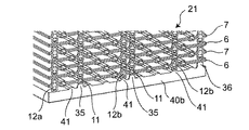
図25は、さらに別の構成の下部エンドプレート40bを示す図である。図25は、プレートフィン積層体21の最下端と下部エンドプレート40bとの接合状態を示す拡大斜視図である。図25に示す構成において、プレートフィン積層体21は、前述の図21に示したプレートフィン積層体21の構成と同じである。図25に示す構成においては、下部エンドプレート40bの上面には、前述の図21に示した流路支持用凸部である突起35と、流路領域支持用凸部である突起36が形成されている。また、下部エンドプレート40bの上面には、プレートフィン積層体21の最下端に配設された、例えば第2プレートフィン7における流路支持部である第2ダボ12bに当接して接合されるダボ支持凸部41が形成されている。ダボ支持凸部41は、長手方向に延設された峰形状の突部であり、対向する第2プレートフィン7における冷媒流路11の間に延設されている。また、ダボ支持凸部41は、第2プレートフィン7において冷媒流路11の間に設けられた第2ダボ12bと確実に当接する高さを有している。なお、プレートフィン積層体21の最下端に配設されるプレートフィン(6、7)の縁部に形成された第1ダボ12aは、下部エンドプレート40bの上面に当接する高さを有している。   FIG. 25 is a view showing a lower end plate 40 b of still another configuration. FIG. 25 is an enlarged perspective view showing a joined state of the lowermost end of the plate fin laminate 21 and the lower end plate 40b. In the configuration shown in FIG. 25, the plate fin laminate 21 is the same as the configuration of the plate fin laminate 21 shown in FIG. 21 described above. In the configuration shown in FIG. 25, on the upper surface of the lower end plate 40b, the protrusion 35 which is the flow path supporting convex portion shown in FIG. 21 described above and the projection 36 which is the flow path region supporting convex portion are formed. ing. Further, on the upper surface of the lower end plate 40b, a dowel is disposed at the lowermost end of the plate fin laminate 21, for example, a dowel which is abutted and joined to the second dowel 12b which is a flow path supporting portion in the second plate fin 7. The support convex portion 41 is formed. The dowel supporting convex portion 41 is a ridge-shaped protruding portion extended in the longitudinal direction, and is extended between the refrigerant channels 11 in the opposing second plate fins 7. In addition, the dowel support convex portion 41 has a height that reliably abuts on the second dowel 12 b provided between the refrigerant channels 11 in the second plate fin 7. The first dowels 12a formed at the edges of the plate fins (6, 7) disposed at the lowermost end of the plate fin laminate 21 have a height to abut the upper surface of the lower end plate 40b. There is.

なお、図25に示したプレートフィン積層体21の最下端面と下部エンドプレート40bの構成に関しては、プレートフィン積層体21の最上端面と上部エンドプレートの下面においても同様に構成することが可能となる。   With regard to the configurations of the lower end surface and the lower end plate 40b of the plate fin laminate 21 shown in FIG. 25, the same can be applied to the uppermost end surface of the plate fin laminate 21 and the lower surface of the upper end plate. Become.

また、前述の図14に変形例を示したように、プレートフィン積層体におけるプレートフィンの一方の端部側(図14においては左側)のみにヘッダ領域Hが形成された構成例においても、図19から図25に示した変形例の構成を適用することが可能であることは言うまでもない。   In addition, as shown in the above-described FIG. 14, even in the configuration example in which the header region H is formed only on one end side (the left side in FIG. 14) of the plate fins in the plate fin laminate. It goes without saying that it is possible to apply the configuration of the modification shown in FIG.

[サイドプレート]
図26は、本開示の熱交換器において、プレートフィン積層体2の上下端に設けたエンドプレート3a、3bを両側面側から挟むように1組のサイドプレート17、18を設けた変形例を示す斜視図である。図26に示す変形例は、プレートフィン積層体2において給入管4が接続された一方のヘッダ領域H側の側面側が、第1サイドプレート17により上下から挟み付けられるように構成されている。また、プレートフィン積層体2において排出管5が接続された他方のヘッダ領域H側の側面側が、第2サイドプレート18により上下から挟み付けられるように構成されている。第1サイドプレート17には、給入管4が貫通する上部開口17aと、プレートフィン積層体2のヘッダ領域に対して第2流体Bである空気が流れ込むように側面開口17bが形成されている。同様に、第2サイドプレート18には、排出管5が貫通する上部開口18aと、プレートフィン積層体2のヘッダ領域Hに対して第2流体Bである空気が流れ込むように側面開口18bが形成されている。
[Side plate]
FIG. 26 shows a modification in which one set of side plates 17 and 18 is provided so as to sandwich the end plates 3a and 3b provided at the upper and lower ends of the plate fin laminate 2 from both sides in the heat exchanger of the present disclosure. It is a perspective view shown. The modified example shown in FIG. 26 is configured such that the side surface side on the side of one header region H to which the inlet pipe 4 is connected in the plate fin laminate 2 is sandwiched by the first side plate 17 from above and below. Further, in the plate fin laminate 2, the side surface side on the side of the other header region H to which the discharge pipe 5 is connected is configured to be vertically held by the second side plate 18. The first side plate 17 is formed with an upper opening 17 a through which the inlet pipe 4 passes and a side opening 17 b so that air as the second fluid B flows into the header region of the plate fin laminate 2. Similarly, the second side plate 18 is formed with an upper opening 18a through which the discharge pipe 5 penetrates and a side opening 18b so that air as the second fluid B flows into the header region H of the plate fin laminate 2 It is done.

上記ように、図26に示した変形例においてはプレートフィン積層体2の両側からヘッダ領域H部分の上下を挟むように1組のサイドプレート17、18が設けられているため、エンドプレート3a、3bとしての厚みを薄くして簡単な構成としても、プレートフィン積層体2を構成するプレートフィン2aにおけるヘッダ領域Hのヘッダ流路10の管壁を上下から所定圧力で確実に押さえることができる構成となる。このように構成されたプレートフィン積層体2は、所望の高い圧力の冷媒をプレートフィン積層体2に流すことができ、効率の高い熱交換が可能な構成となる。   As described above, in the modified example shown in FIG. 26, since the pair of side plates 17 and 18 is provided to sandwich the upper and lower portions of the header region H from both sides of the plate fin laminate 2, the end plate 3a, Even if the thickness as 3b is made thin and simple structure, the pipe wall of the header channel 10 of the header region H in the plate fin 2a constituting the plate fin laminate 2 can be reliably held down by predetermined pressure from above and below It becomes. The plate fin laminate 2 configured as described above can flow a desired high pressure refrigerant to the plate fin laminate 2 and can be configured to be capable of highly efficient heat exchange.

なお、図26においては、図1に示したプレートフィン積層体2に対する構成例として説明したが、図19から図25を用いて説明した変形例の構成においても、1組のサイドプレート17、18を設けて、プレートフィン積層体を上下か挟み付ける構成とすることが可能である。このような変形例の構成においても、プレートフィン積層体を上下から所定圧力で確実に押さえることができ、所望の高い圧力の冷媒をプレートフィン積層体に流すことができ、効率の高い熱交換が可能な構成となる。   Although FIG. 26 is described as a configuration example for the plate fin laminate 2 shown in FIG. 1, one set of side plates 17 and 18 is also used in the configuration of the modification described with reference to FIGS. 19 to 25. Can be provided to hold the plate fin laminate vertically. Even in the configuration of such a modification, the plate fin laminate can be reliably pressed from above and below at a predetermined pressure, and a refrigerant of a desired high pressure can be flowed through the plate fin laminate, and heat exchange with high efficiency is achieved. It will be possible configuration.

上記のように、本開示に係る熱交換器の構成においては、軽量化、小型化および高い熱交換の効率化を達成することができると共に、プレートフィン積層体におけるプレートフィンに高圧の冷媒が流れる構成であっても信頼性が高く、熱交換効率の高い熱交換器となる。   As described above, in the configuration of the heat exchanger according to the present disclosure, it is possible to achieve weight reduction, miniaturization, and high efficiency of heat exchange, and a high-pressure refrigerant flows through the plate fins in the plate fin laminate. Even with the configuration, the heat exchanger has high reliability and high heat exchange efficiency.

本開示は、軽量化および小型化された装置であって、信頼性および効率の高い熱交換を実施できるため、市場価値の高い熱交換器となる。   The present disclosure is a lightweight and miniaturized device that can perform heat exchange with high reliability and efficiency, and thus becomes a heat exchanger with high market value.

1 熱交換器
2 プレートフィン積層体
2a プレートフィン
3 エンドプレート
4 給入管(入口ヘッダ)
5 排出管(出口ヘッダ)
6 第1プレートフィン
7 第2プレートフィン
8 ヘッダ開口
9 位置決めピン
10 ヘッダ流路
10a 外周流路
10b 迂回流路
10c 多分岐流路
11 冷媒流路(第1流体流路)
12 突起
12a 第1ダボ(流路領域支持部)
12b 第2ダボ(流路支持部)
13 位置決め孔
13a 位置決め外周部(ヘッダ領域支持部)
17 第1サイドプレート
18 第2サイドプレート
1 heat exchanger 2 plate fin laminate 2a plate fin 3 end plate 4 inlet pipe (inlet header)
5 Exhaust pipe (outlet header)
6 1st plate fin 7 2nd plate fin 8 header opening 9 positioning pin 10 header channel 10a outer peripheral channel 10b bypass channel 10c multiple branch channel 11 refrigerant channel (first fluid channel)
12 projection 12a first dowel (flow passage area support portion)
12b Second dowel (channel support)
13 Positioning hole 13a Positioning outer peripheral part (header area support part)
17 1st side plate 18 2nd side plate

Claims (23)

第1流体が流れる流路を有するプレートフィンを積層したプレートフィン積層体と、
前記プレートフィン積層体における各プレートフィンの流路に流れる前記第1流体が通過する給排管と、を備え、
前記プレートフィン積層体の積層間に第2流体を流して、前記第1流体と前記第2流体との間で熱交換する熱交換器であって、
前記プレートフィンは、
前記第1流体が並行に流れるように、直線状の第1流体流路を複数有する流路領域と、
前記流路領域の各第1流体流路と前記給排管とを連通させるヘッダ流路を有するヘッダ領域と、
前記ヘッダ流路の外壁が、前記プレートフィン積層体において積層方向に隣接するプレートフィンのヘッダ流路の外壁と当接するよう構成され、
前記ヘッダ領域が両側に設けられた前記プレートフィンにおいて、それぞれの前記ヘッダ流路が前記給排管と多分岐流路とを連通させる迂回流路を含み、前記プレートフィンの両側に配設された前記迂回流路と多分岐流路が、前記プレートフィンの中心を対称の中心とした点対称の形状を有するように構成された熱交換器。
A plate fin laminate in which plate fins having a flow path through which the first fluid flows are stacked;
And a supply / discharge pipe through which the first fluid flows in the flow path of each plate fin in the plate fin laminate.
A heat exchanger for flowing a second fluid between the stacks of the plate fin stacks to exchange heat between the first fluid and the second fluid,
The plate fins are
A flow passage region having a plurality of linear first fluid flow passages such that the first fluid flows in parallel;
A header area having a header flow path for communicating each first fluid flow path of the flow path area with the supply and discharge pipe;
The outer wall of the header channel is configured to contact the outer wall of the header channel of the plate fin adjacent in the stacking direction in the plate fin laminate ,
In the plate fins provided with the header regions on both sides, each of the header channels includes bypass channels that connect the supply and discharge pipe and the multi-branch channel, and are disposed on both sides of the plate fins The heat exchanger according to claim 1, wherein the bypass flow passage and the multi-branch flow passage have a point-symmetrical shape centered on the center of the plate fin .
前記ヘッダ流路は、前記給排管の冷媒を前記流路領域の各第1流体流路に流すための多分岐流路を有する請求項1に記載の熱交換器。   The heat exchanger according to claim 1, wherein the header flow path has a multi-branch flow path for flowing the refrigerant of the supply and discharge pipe to each first fluid flow path of the flow path region. 前記多分岐流路が、前記プレートフィン積層体における積層方向で隣接するプレートフィンにおける多分岐流路の外壁に当接するよう構成された請求項2に記載の熱交換器。   The heat exchanger according to claim 2, wherein the multi-branched flow path is configured to abut on an outer wall of a multi-branched flow path in adjacent plate fins in the stacking direction in the plate fin laminate. 前記ヘッダ領域において、前記ヘッダ流路の管壁が他の部位より厚く形成された請求項1から3のいずれか一項に記載の熱交換器。   The heat exchanger according to any one of claims 1 to 3, wherein in the header region, a tube wall of the header flow passage is formed thicker than other portions. 前記流路領域において、前記流路の管壁が他の部位より厚く形成された請求項1から4のいずれか一項に記載の熱交換器。   The heat exchanger according to any one of claims 1 to 4, wherein in the flow passage area, a pipe wall of the flow passage is formed thicker than other portions. 前記プレートフィンにおいて、両側の前記ヘッダ領域の前記ヘッダ流路が対称的な形状を有するよう構成された請求項1から4のいずれか一項に記載の熱交換器。 The plate fins Te odor, heat exchanger according to any one of claims 1 to 4, wherein the header channel of the header area of both sides is configured so as to have a symmetrical shape. 前記ヘッダ領域が両側に設けられた前記プレートフィンにおいて、前記ヘッダ領域に流路と異なる突出した複数のヘッダ領域支持部が形成され、前記プレートフィンの両側に配設された前記ヘッダ領域支持部は、前記プレートフィンの中心を対称の中心とした点対称の形状を有するように構成された請求項1から6のいずれか一項に記載の熱交換器。 In the plate fin in which the header area is provided on both sides, a plurality of projecting header area supporting portions different from the flow path are formed in the header area, and the header area supporting portions disposed on both sides of the plate fin The heat exchanger according to any one of claims 1 to 6 , wherein the heat exchanger is configured to have a point-symmetrical shape with the center of the plate fin as the center of symmetry. 前記プレートフィンにおいて、前記ヘッダ領域が一端側に設けられ、前記給排管が前記ヘッダ領域に対応する位置に設けられた請求項1から5のいずれか一項に記載の熱交換器。   The heat exchanger according to any one of claims 1 to 5, wherein in the plate fin, the header region is provided at one end side, and the supply and discharge pipe is provided at a position corresponding to the header region. 前記プレートフィンにおける前記ヘッダ領域に流路と異なる突出した複数のヘッダ領域支持部が形成され、前記ヘッダ領域支持部が前記プレートフィン積層体における積層方向で隣接する前記プレートフィンの前記ヘッダ領域と当接して積層方向で隣接する前記プレートフィンの間に所定空間を形成するように構成された請求項1から8のいずれか一項に記載の熱交換器。 A plurality of projecting header area supporting portions different from the flow path are formed in the header area of the plate fin, and the header area supporting portion is in contact with the header area of the plate fin adjacent in the stacking direction in the plate fin laminate. The heat exchanger according to any one of claims 1 to 8 , configured to form a predetermined space between the plate fins adjacent in the stacking direction in contact with each other. 前記ヘッダ領域に設けられた前記ヘッダ領域支持部における少なくとも二つが貫通孔を有し、当該貫通孔が位置決め孔となるように構成された請求項9に記載の熱交換器。 10. The heat exchanger according to claim 9 , wherein at least two of the header area support portions provided in the header area have through holes, and the through holes serve as positioning holes. 前記位置決め孔に位置決めピンが固着された請求項10に記載の熱交換器。 The heat exchanger according to claim 10 , wherein positioning pins are fixed to the positioning holes. 前記プレートフィンにおける前記流路領域に流路と異なる突出した流路領域支持部が形成され、前記流路領域支持部が前記プレートフィン積層体における積層方向で隣接する前記プレートフィンの前記流路領域と当接して積層間に所定空間を形成するよう構成された請求項1から11のいずれか一項に記載の熱交換器。 The flow path region supporting portion different from the flow path is formed in the flow path region of the plate fin, and the flow path region of the plate fin adjacent to the flow path region supporting portion in the stacking direction of the plate fin laminate The heat exchanger according to any one of the preceding claims , wherein the heat exchanger is configured to abut on to form a predetermined space between the stacks. 前記プレートフィン積層体は、異なる流路形状を有する前記プレートフィンが積層されて構成された請求項1から12のいずれか一項に記載の熱交換器。 The heat exchanger according to any one of claims 1 to 12 , wherein the plate fin laminate is configured by laminating the plate fins having different flow channel shapes. 前記プレートフィン積層体は、二種類の流路形状を有する前記プレートフィンが交互に積層されて構成された請求項1から12のいずれか一項に記載の熱交換器。 The heat exchanger according to any one of claims 1 to 12 , wherein the plate fin laminate is configured by alternately laminating the plate fins having two types of flow path shapes. 前記プレートフィン積層体は、前記流路領域における前記第1流体が流れる方向に直交する断面において、交互に積層された前記プレートフィンにおける流路が千鳥配列となるよう構成された請求項14に記載の熱交換器。 15. The plate fin laminate according to claim 14 , wherein the channels in the plate fins alternately stacked are arranged in a zigzag in a cross section orthogonal to the direction in which the first fluid flows in the channel region. Heat exchanger. 前記プレートフィンにおける前記流路領域に流路と異なる突出した流路支持部が形成され、前記流路支持部が前記プレートフィン積層体における積層方向で隣接する前記プレートフィンの前記流路領域における前記第1流体流路の管壁と当接するよう構成された請求項13または14に記載の熱交換器。 A projecting flow path support portion different from the flow path is formed in the flow path region of the plate fin, and the flow path support portion is in the flow path region of the plate fin adjacent in the stacking direction in the plate fin laminate. 15. A heat exchanger according to claim 13 or 14 , configured to abut the tube wall of the first fluid flow path. 前記プレートフィンにおいて突設された前記流路支持部は、前記プレートフィン積層体の積層間に流れる第2流体の流れ方向に対して千鳥配列に配設された請求項16に記載の熱交換器。 The heat exchanger according to claim 16 , wherein the flow path support portions provided to project in the plate fins are arranged in a staggered arrangement with respect to the flow direction of the second fluid flowing between the stacks of the plate fin laminates. . 前記プレートフィンにおいて突設された前記流路支持部の数は、第2流体Bの流れ方向において、風下側が風上側より多く設けた請求項16に記載の熱交換器。 The heat exchanger according to claim 16 , wherein the number of the flow path support portions provided in the plate fins is greater than the windward side on the leeward side in the flow direction of the second fluid B. 二種類の流路形状を有する前記プレートフィンにおいて、一方の前記プレートフィンの前記流路領域に流路と異なる突出した流路領域凸部が形成され、他方の前記プレートフィンの前記流路領域に前記流路領域凸部と対応する位置に流路領域凹部が形成され、前記プレートフィン積層体における積層方向で隣接する前記プレートフィンの前記流路領域凸部と前記流路領域凹部が係合して、隣接する前記プレートフィンの積層間が所定空間を保持するように構成された請求項14に記載の熱交換器。 In the plate fin having two types of flow path shapes, a protruding flow path area convex portion different from the flow path is formed in the flow path area of one of the plate fins, and in the flow path area of the other plate fin A flow passage region concave portion is formed at a position corresponding to the flow passage region convex portion, and the flow passage region convex portion and the flow passage region concave portion of the plate fin adjacent in the stacking direction in the plate fin laminate engage with each other. The heat exchanger according to claim 14 , wherein the space between adjacent ones of the plate fins is a predetermined space. 前記プレートフィンにおける少なくとも前記流路領域の流路は、当該流路における前記第1流体が流れる方向に直交する断面が矩形形状である請求項1から19のいずれか一項に記載の熱交換器。 The heat exchanger according to any one of claims 1 to 19 , wherein at least the flow passage in the flow passage region of the plate fin has a rectangular cross section orthogonal to the direction in which the first fluid flows in the flow passage. . 前記プレートフィンにおける少なくとも前記流路領域の流路は、当該流路における前記第1流体が流れる方向に直交する断面が円形形状である請求項1から19のいずれか一項に記載の熱交換器。 The heat exchanger according to any one of claims 1 to 19 , wherein at least the flow passage in the flow passage region of the plate fin has a circular cross section orthogonal to the flow direction of the first fluid in the flow passage. . 前記プレートフィンにおける少なくとも前記流路領域の流路は、前記プレートフィン積層体における積層方向の一方側にのみ突出して形成された請求項1から21のいずれか一項に記載の熱交換器。 The heat exchanger according to any one of claims 1 to 21 , wherein at least the flow passage of the flow passage region in the plate fin is formed so as to protrude only on one side in the stacking direction of the plate fin laminate. 前記プレートフィンにおける少なくとも前記流路領域の流路は、前記プレートフィン積層体における積層方向の両側に突出して形成された請求項1から21のいずれか一項に記載の熱交換器。 The heat exchanger according to any one of claims 1 to 21 , wherein at least the flow passage of the flow passage region in the plate fin is formed to protrude on both sides in the stacking direction of the plate fin laminate.
JP2016063296A 2016-03-28 2016-03-28 Heat exchanger Active JP6504367B2 (en)

Priority Applications (4)

Application Number Priority Date Filing Date Title
JP2016063296A JP6504367B2 (en) 2016-03-28 2016-03-28 Heat exchanger
CN201780019132.0A CN108885075B (en) 2016-03-28 2017-02-27 Heat exchanger
PCT/JP2017/007273 WO2017169410A1 (en) 2016-03-28 2017-02-27 Heat exchanger
DE112017001572.3T DE112017001572T5 (en) 2016-03-28 2017-02-27 heat exchangers

Applications Claiming Priority (1)

Application Number Priority Date Filing Date Title
JP2016063296A JP6504367B2 (en) 2016-03-28 2016-03-28 Heat exchanger

Publications (2)

Publication Number Publication Date
JP2017180856A JP2017180856A (en) 2017-10-05
JP6504367B2 true JP6504367B2 (en) 2019-04-24

Family

ID=59964209

Family Applications (1)

Application Number Title Priority Date Filing Date
JP2016063296A Active JP6504367B2 (en) 2016-03-28 2016-03-28 Heat exchanger

Country Status (4)

Country Link
JP (1) JP6504367B2 (en)
CN (1) CN108885075B (en)
DE (1) DE112017001572T5 (en)
WO (1) WO2017169410A1 (en)

Cited By (1)

* Cited by examiner, † Cited by third party
Publication number Priority date Publication date Assignee Title
JP2021063639A (en) * 2019-10-17 2021-04-22 パナソニックIpマネジメント株式会社 Heat exchanger

Families Citing this family (12)

* Cited by examiner, † Cited by third party
Publication number Priority date Publication date Assignee Title
JP6528283B2 (en) * 2016-03-28 2019-06-12 パナソニックIpマネジメント株式会社 Heat exchanger
JP2019152348A (en) * 2018-03-01 2019-09-12 パナソニックIpマネジメント株式会社 Heat exchange unit and air conditioner using the same
JP6887074B2 (en) * 2018-03-05 2021-06-16 パナソニックIpマネジメント株式会社 Heat exchanger
JP6887075B2 (en) * 2018-03-19 2021-06-16 パナソニックIpマネジメント株式会社 Heat exchanger and freezing system using it
JP6865354B2 (en) * 2018-04-09 2021-04-28 パナソニックIpマネジメント株式会社 Plate fin laminated heat exchanger and refrigeration system using it
CN109028660A (en) * 2018-05-09 2018-12-18 河南科隆集团有限公司 A kind of finned evaporator and preparation method thereof
JP6934609B2 (en) * 2019-04-17 2021-09-15 パナソニックIpマネジメント株式会社 Heat exchanger and freezing system using it
JP2020176768A (en) * 2019-04-18 2020-10-29 パナソニックIpマネジメント株式会社 Heat exchanger and refrigeration system using the same
CN112066598A (en) * 2019-06-11 2020-12-11 广东美的制冷设备有限公司 Heat exchanger and air conditioning equipment
JP7365634B2 (en) * 2019-10-17 2023-10-20 パナソニックIpマネジメント株式会社 Heat exchanger
KR102393899B1 (en) * 2020-07-09 2022-05-02 두산에너빌리티 주식회사 Heat exchanging device comprising printed circuit heat exchanger
CN113294941A (en) * 2021-07-05 2021-08-24 珠海市华晶农谷微冻瞬冷科学研究院 Special plate evaporator for refrigeration evaporation system and working method thereof

Family Cites Families (11)

* Cited by examiner, † Cited by third party
Publication number Priority date Publication date Assignee Title
JPH021U (en) * 1988-06-06 1990-01-05
JP2001208487A (en) * 2000-01-28 2001-08-03 Mitsubishi Heavy Ind Ltd Evaporator integrated with combustion catalyst
JP3965901B2 (en) * 2000-10-27 2007-08-29 株式会社デンソー Evaporator
JP4770534B2 (en) * 2006-03-22 2011-09-14 パナソニック株式会社 Heat exchanger
JP2007285691A (en) * 2006-03-22 2007-11-01 Matsushita Electric Ind Co Ltd Heat exchanger
JP4231518B2 (en) * 2006-10-24 2009-03-04 トヨタ自動車株式会社 Heat exchanger
JP2008116102A (en) * 2006-11-02 2008-05-22 Denso Corp Heat exchanger for cooling
CN201954990U (en) * 2010-05-13 2011-08-31 艾普尔换热器(苏州)有限公司 Plate type heat exchanger
FR2980837B1 (en) * 2011-10-04 2015-06-26 Valeo Systemes Thermiques HEAT EXCHANGER WITH STACKED PLATES.
JP3192719U (en) * 2014-06-18 2014-08-28 有限会社和氣製作所 Plate member and heat exchanger
JP6531325B2 (en) * 2015-02-18 2019-06-19 有限会社和氣製作所 Heat exchanger

Cited By (3)

* Cited by examiner, † Cited by third party
Publication number Priority date Publication date Assignee Title
JP2021063639A (en) * 2019-10-17 2021-04-22 パナソニックIpマネジメント株式会社 Heat exchanger
WO2021075336A1 (en) * 2019-10-17 2021-04-22 パナソニックIpマネジメント株式会社 Heat exchanger
JP7365635B2 (en) 2019-10-17 2023-10-20 パナソニックIpマネジメント株式会社 Heat exchanger

Also Published As

Publication number Publication date
WO2017169410A1 (en) 2017-10-05
DE112017001572T5 (en) 2018-12-20
CN108885075A (en) 2018-11-23
JP2017180856A (en) 2017-10-05
CN108885075B (en) 2020-08-04

Similar Documents

Publication Publication Date Title
JP6504367B2 (en) Heat exchanger
JP6528283B2 (en) Heat exchanger
US9766015B2 (en) Heat exchanger
JP6116702B2 (en) Laminated header, heat exchanger, heat exchanger manufacturing method, and air conditioner
CN102494547A (en) Miniature micro-channel plate-fin heat exchanger
CN113424009B (en) Heat exchanger
JP2010114174A (en) Core structure for heat sink
TW200538695A (en) Heat exchanger and method of producing the same
JP6267954B2 (en) Plate heat exchanger
JP4482997B2 (en) Laminated heat exchanger and manufacturing method thereof
KR102634169B1 (en) Stacked plate type heat exchanger
JP2005326068A (en) Plate for heat exchanger and heat exchanger
JP2002107073A (en) Laminated heat exchanger
WO2021075336A1 (en) Heat exchanger
JP6720890B2 (en) Stacked heat exchanger
JP5947158B2 (en) Outdoor heat exchanger for heat pump
JP2005308232A (en) Heat exchanger
JP6102612B2 (en) Heat exchanger
JP4765619B2 (en) Heat exchanger and manufacturing method thereof
JP2020201021A (en) Heat exchanger
JP2000329490A (en) Multilayer heat exchanger
JP2007163114A (en) Plate laminated type heat exchanger
EP1712864A1 (en) Method of forming a heat exchanger and a spacer therefor
JP2016223648A (en) Heat exchanger, heat exchange module and manufacturing method of heat exchanger

Legal Events

Date Code Title Description
A621 Written request for application examination

Free format text: JAPANESE INTERMEDIATE CODE: A621

Effective date: 20180220

A131 Notification of reasons for refusal

Free format text: JAPANESE INTERMEDIATE CODE: A131

Effective date: 20180828

A521 Request for written amendment filed

Free format text: JAPANESE INTERMEDIATE CODE: A523

Effective date: 20181025

TRDD Decision of grant or rejection written
A01 Written decision to grant a patent or to grant a registration (utility model)

Free format text: JAPANESE INTERMEDIATE CODE: A01

Effective date: 20190305

A61 First payment of annual fees (during grant procedure)

Free format text: JAPANESE INTERMEDIATE CODE: A61

Effective date: 20190312

R151 Written notification of patent or utility model registration

Ref document number: 6504367

Country of ref document: JP

Free format text: JAPANESE INTERMEDIATE CODE: R151