JP2007285691A - Heat exchanger - Google Patents

Heat exchanger Download PDF

Info

Publication number
JP2007285691A
JP2007285691A JP2007064768A JP2007064768A JP2007285691A JP 2007285691 A JP2007285691 A JP 2007285691A JP 2007064768 A JP2007064768 A JP 2007064768A JP 2007064768 A JP2007064768 A JP 2007064768A JP 2007285691 A JP2007285691 A JP 2007285691A
Authority
JP
Japan
Prior art keywords
rib
shielding
heat exchanger
unit elements
ribs
Prior art date
Legal status (The legal status is an assumption and is not a legal conclusion. Google has not performed a legal analysis and makes no representation as to the accuracy of the status listed.)
Pending
Application number
JP2007064768A
Other languages
Japanese (ja)
Other versions
JP2007285691A5 (en
Inventor
Takuya Murayama
拓也 村山
Current Assignee (The listed assignees may be inaccurate. Google has not performed a legal analysis and makes no representation or warranty as to the accuracy of the list.)
Panasonic Holdings Corp
Original Assignee
Matsushita Electric Industrial Co Ltd
Priority date (The priority date is an assumption and is not a legal conclusion. Google has not performed a legal analysis and makes no representation as to the accuracy of the date listed.)
Filing date
Publication date
Application filed by Matsushita Electric Industrial Co Ltd filed Critical Matsushita Electric Industrial Co Ltd
Priority to JP2007064768A priority Critical patent/JP2007285691A/en
Publication of JP2007285691A publication Critical patent/JP2007285691A/en
Publication of JP2007285691A5 publication Critical patent/JP2007285691A5/ja
Pending legal-status Critical Current

Links

Images

Abstract

<P>PROBLEM TO BE SOLVED: To provide a heat exchanger used in a total enthalpy heat exchange type ventilation device, capable of improving mass-productivity, reducing manufacturing costs and preventing leakage of airflow. <P>SOLUTION: In this heat exchanger 1a wherein an unit element 2a is formed by integrally molding spacial ribs 6a, 6aa for keeping a space between a heat transfer plate 4 and a heat transfer plate 4, and shielding ribs 7a, 7aa for shielding the leakage of airflow, with a resin, the plurality of unit elements 2 are stacked to form a ventilation flue 5 between the heat transfer plates 4, and the primary airflow and the secondary airflow are circulated to the ventilation flue 5 to exchange heat through the heat transfer plates 4, shielding rib injection ports 14a and spacial rib injection ports 15 are formed on positions connected to the spacial ribs 6a, 6aa and the shielding ribs 7a, 7aa as injection ports for injecting a molten resin. <P>COPYRIGHT: (C)2008,JPO&INPIT

Description

本発明は、家庭用の熱交換型換気扇やビルなどの全熱交換型換気装置に使用する積層構造の熱交換器に関するものである。   The present invention relates to a heat exchanger having a laminated structure used for a total heat exchange type ventilation device such as a heat exchange type ventilation fan or a building for home use.

従来、この種の熱交換器は、通風抵抗や熱交換効率などの基本的機能を向上しつつ製造コストを抑えるために、伝熱板とスペーサーとを接合せずに積層することによって熱交換器を形成したものもある(例えば、特許文献1参照)。   Conventionally, this type of heat exchanger is a heat exchanger by laminating heat transfer plates and spacers without joining them, in order to improve the basic functions such as ventilation resistance and heat exchange efficiency and to suppress the manufacturing cost. Some of them are formed (see, for example, Patent Document 1).

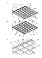
以下、その熱交換器について、図21(a)、図21(b)、図22を参照しながら説明する。   Hereinafter, the heat exchanger will be described with reference to FIGS. 21 (a), 21 (b), and 22.

図に示すように、合成樹脂よりなるスペーサー101は、伝熱板102間の間隔を保持する間隔リブ103と、間隔リブ103同士を連結する連結リブ104と、間隔リブ103および連結リブ104上に配置された小突起105と、上下に積層したスペーサーの相対する面に、互いに嵌合する凸部106と凹部107を一体成形することによって得られる。伝熱性と透湿性または伝熱性のみを有する伝熱板102は、位置合わせ用穴108を備えたものである。また、位置合わせ用穴108は、スペーサー101と伝熱板102を積層した際に小突起105と嵌合するものである。   As shown in the figure, the spacer 101 made of synthetic resin is provided on the interval rib 103 that holds the interval between the heat transfer plates 102, the connecting rib 104 that connects the interval ribs 103, and the interval rib 103 and the connecting rib 104. The protrusions 106 and the recesses 107 that are fitted to each other are obtained by integrally molding the small protrusions 105 arranged on the opposing surfaces of the vertically stacked spacers. The heat transfer plate 102 having only heat transfer and moisture permeability or heat transfer is provided with an alignment hole 108. The alignment hole 108 is to be fitted to the small protrusion 105 when the spacer 101 and the heat transfer plate 102 are laminated.

熱交換器109はスペーサー101を交互に90度ずらしながら積層し、スペーサー101間に伝熱板102を介在させることによって得られる。また、熱交換器109はスペーサー101の四隅に設けた凸部106と凹部107が嵌合しながらスペーサー101同士を連結保持する。   The heat exchanger 109 is obtained by stacking the spacers 101 while being alternately shifted by 90 degrees and interposing the heat transfer plate 102 between the spacers 101. The heat exchanger 109 connects and holds the spacers 101 while the convex portions 106 and the concave portions 107 provided at the four corners of the spacer 101 are fitted.

上記構成において、一次気流Aと二次気流Bを流通すると、伝熱板102を介して一次気流Aと二次気流Bの間で熱交換する。
特許第3023546号公報
In the above configuration, when the primary airflow A and the secondary airflow B are circulated, heat exchange is performed between the primary airflow A and the secondary airflow B via the heat transfer plate 102.
Japanese Patent No. 3023546

このような従来の熱交換器109はスペーサー101と伝熱板102を接合せずに積層したものであるため、積層のずれに起因する密封性の低下による気流の漏れが増加するという課題があり、積層のずれに起因する密封性の低下による気流の漏れを防止することが要求されている。   Since such a conventional heat exchanger 109 is formed by laminating the spacer 101 and the heat transfer plate 102 without joining, there is a problem in that airflow leakage increases due to a decrease in sealing performance caused by misalignment of the lamination. Therefore, it is required to prevent airflow leakage due to a decrease in hermeticity due to stacking deviation.

また、スペーサー101は射出成形などの成形手段を用いて合成樹脂から形成されるが、溶融樹脂が注入される注入口においてバリが発生した場合、スペーサー101を積層した際に隣接するスペーサー101同士が干渉し、スペーサー101と伝熱板4または隣接するスペーサー101との間に隙間ができ、密封性の低下による気流の漏れが増加するという課題があり、バリによって生じる単位素子間の隙間を無くすことによる気流の漏れを防止することが要求されている。   In addition, the spacer 101 is formed from a synthetic resin using a molding means such as injection molding. However, when burrs are generated at the injection port into which the molten resin is injected, the adjacent spacers 101 are adjacent to each other when the spacers 101 are stacked. There is a problem that a gap is formed between the spacer 101 and the heat transfer plate 4 or the adjacent spacer 101 due to interference, and there is a problem that airflow leakage increases due to a decrease in sealing performance, and the gap between unit elements caused by burrs is eliminated. It is required to prevent airflow leakage due to the above.

また、熱交換器109は合成樹脂よりなるスペーサー101と伝熱板102の二つの部品を別々に用いて形成されるため、部品点数が多く、加工工程が多くなるため、製造コストが高く、量産性が低くなるという課題があり、製造コストを低減することおよび量産性を向上することが要求されている。   Further, since the heat exchanger 109 is formed by separately using two parts of the spacer 101 made of synthetic resin and the heat transfer plate 102, the number of parts is increased and the number of processing steps is increased. There is a problem that the productivity is lowered, and it is required to reduce the manufacturing cost and improve the mass productivity.

また、スペーサー101は射出成形などの成形手段を用いて合成樹脂から形成されるが、スペーサー101の複数の間隔リブ103は連結リブ104によって連結しているため、複数の間隔リブ103同士は連結部が無く、溶融樹脂を射出成形する注入口を間隔リブ103に隣接する部分に設けた場合、射出成形金型内において注入口から注入された溶融樹脂は、間隔リブ103から連結リブ104に流れ、更に他の間隔リブ103へ流れるので、樹脂成形する射出圧力が高くなり、大型の成形機が必要になって設備投資が高額になり、製造コストが高くなる。   The spacer 101 is made of synthetic resin using a molding means such as injection molding. Since the plurality of spacing ribs 103 of the spacer 101 are connected by the connecting rib 104, the plurality of spacing ribs 103 are connected to each other. If the injection port for injection molding the molten resin is provided in a portion adjacent to the spacing rib 103, the molten resin injected from the injection port in the injection mold flows from the spacing rib 103 to the connecting rib 104, Furthermore, since it flows to the other spacing rib 103, the injection pressure for resin molding becomes high, a large molding machine is required, and the capital investment becomes high, and the manufacturing cost increases.

また溶融樹脂を射出成形する注入口を連結リブ104に隣接する部分に設けた場合、射出成形金型内において注入口から注入された溶融樹脂は、連結リブ104から複数の間隔リブ103に順々に流れるので、樹脂成形する射出圧力が高くなり、大型の成形機が必要になって設備投資が高額になり、製造コストが高くなるという課題があり、樹脂成形機の能力を小さくすることによって設備投資を小さくし、製造コストを低減することが要求されている。   Further, when an injection port for injection molding of the molten resin is provided in a portion adjacent to the connecting rib 104, the molten resin injected from the injection port in the injection mold is sequentially supplied from the connecting rib 104 to the plurality of interval ribs 103. Therefore, there is a problem that the injection pressure for resin molding is high, a large molding machine is required, capital investment is high, and manufacturing costs are high, and equipment is reduced by reducing the capacity of the resin molding machine. There is a need to reduce investment and reduce manufacturing costs.

本発明は、このような従来の課題を解決するものであり、量産性を向上することができ、また部品点数が少なく、加工工程を少なくすることによる量産性を向上することができ、また製造コストを低減することができ、また部品点数が少なく、加工工程を少なくすることによる製造コストを低減することができ、また樹脂成形機の能力を小さくすることによって設備投資を小さくし、製造コストを低減することができ、また気流の漏れを防止することができ、またバリによって生じる単位素子間の隙間を無くすことによる気流の漏れを防止することができる熱交換器を提供することを目的としている。   The present invention solves such a conventional problem, can improve mass productivity, can reduce the number of parts, can improve mass productivity by reducing processing steps, and can be manufactured. The cost can be reduced, the number of parts can be reduced, the manufacturing cost can be reduced by reducing the number of processing steps, and the equipment investment can be reduced by reducing the capacity of the resin molding machine. An object of the present invention is to provide a heat exchanger capable of reducing airflow leakage and preventing airflow leakage by eliminating gaps between unit elements caused by burrs. .

本発明の熱交換器は上記目的を達成するために、伝熱板と前記伝熱板の間隔を保持するための間隔リブと気流の漏れを遮蔽するための遮蔽リブとを樹脂にて一体成形して単位素子を形成し、この単位素子を複数積層することにより前記伝熱板間に通風路が形成され、一次気流と二次気流を前記通風路に流通することにより、前記伝熱板を介して熱交換するようにした熱交換器において、前記間隔リブまたは前記遮蔽リブの少なくとも何れか、または前記間隔リブまたは前記遮蔽リブの少なくとも何れかに連結する位置に溶融樹脂を注入する注入口を設け、前記間隔リブおよび前記遮蔽リブが何れかで連結しているものである。   In order to achieve the above object, the heat exchanger according to the present invention integrally forms a heat transfer plate, a spacing rib for maintaining a space between the heat transfer plate and a shielding rib for shielding airflow leakage with resin. A unit element is formed, and a plurality of unit elements are stacked to form a ventilation path between the heat transfer plates, and a primary airflow and a secondary airflow are circulated through the ventilation path, whereby the heat transfer plate is In the heat exchanger configured to exchange heat via, an inlet for injecting molten resin into a position connected to at least one of the spacing rib or the shielding rib, or at least one of the spacing rib or the shielding rib The spacing ribs and the shielding ribs are connected to each other.

この手段により部品点数が少なく、加工工程を少なくすることによる量産性を向上することができ、また部品点数が少なく、加工工程を少なくすることによる製造コストを低減することができる熱交換器が得られる。   By this means, a heat exchanger can be obtained in which the number of parts is small and mass productivity can be improved by reducing the number of processing steps, and the number of parts is small and manufacturing costs can be reduced by reducing the number of processing steps. It is done.

また他の手段は、注入口は、単位素子を積層した時に隣接する前記単位素子が干渉しないように逃がす手段を備えたものである。   As another means, the injection port is provided with means for allowing the adjacent unit elements to escape when they are stacked so as not to interfere with each other.

この手段によりバリによって生じる単位素子間の隙間を無くすことによる気流の漏れを防止することができる熱交換器が得られる。   By this means, it is possible to obtain a heat exchanger that can prevent airflow leakage due to elimination of gaps between unit elements caused by burrs.

また他の手段は、逃がす手段として、間隔リブまたは遮蔽リブの少なくとも何れかに段落としを設けたものである。   The other means is provided with a paragraph as at least one of the spacing rib and the shielding rib as the escape means.

この手段によりバリによって生じる単位素子間の隙間を無くすことによる気流の漏れを防止することができる熱交換器が得られる。   By this means, it is possible to obtain a heat exchanger that can prevent airflow leakage due to elimination of gaps between unit elements caused by burrs.

また他の手段は、段落としは、間隔リブまたは遮蔽リブの少なくとも何れかに連結し、通風路内に設けたものである。   Another means is that the paragraph is connected to at least one of the interval rib and the shielding rib and provided in the ventilation path.

この手段によりバリによって生じる単位素子間の隙間を無くすことによる気流の漏れを防止することができる熱交換器が得られる。   By this means, it is possible to obtain a heat exchanger that can prevent airflow leakage due to elimination of gaps between unit elements caused by burrs.

また他の手段は、段落としは、遮蔽リブに連結し、通風路外に設けたものである。   As another means, the paragraph is connected to the shielding rib and provided outside the ventilation path.

この手段によりバリによって生じる単位素子間の隙間を無くすことによる気流の漏れを防止することができる熱交換器が得られる。   By this means, it is possible to obtain a heat exchanger that can prevent airflow leakage due to elimination of gaps between unit elements caused by burrs.

また他の手段は、段落としは、遮蔽リブと間隔リブが交差する位置に設けたものである。   Another means is that the paragraph is provided at a position where the shielding rib and the spacing rib intersect.

この手段により製造コストを低減することができる熱交換器が得られる。   By this means, a heat exchanger capable of reducing the manufacturing cost can be obtained.

また他の手段は、複数の間隔リブは何れかの間隔リブで連結しているものである。   In another means, the plurality of spacing ribs are connected by any spacing rib.

この手段により製造コストを低減することができる熱交換器が得られる。   By this means, a heat exchanger capable of reducing the manufacturing cost can be obtained.

本発明によれば量産性を向上することができるという効果のある熱交換器を提供できる。   ADVANTAGE OF THE INVENTION According to this invention, the heat exchanger with the effect that mass productivity can be improved can be provided.

また、部品点数が少なく、加工工程を少なくすることによる量産性を向上することができるという効果のある熱交換器を提供できる。   In addition, it is possible to provide a heat exchanger that has an effect of reducing the number of parts and improving the mass productivity by reducing the number of processing steps.

また、製造コストを低減することができるという効果のある熱交換器を提供できる。   In addition, it is possible to provide a heat exchanger that has an effect of reducing the manufacturing cost.

また、部品点数が少なく、加工工程を少なくすることによる製造コストを低減することができるという効果のある熱交換器を提供できる。   Further, it is possible to provide a heat exchanger that has an effect that the number of parts is small and the manufacturing cost can be reduced by reducing the number of processing steps.

また、樹脂成形機の能力を小さくすることによって設備投資を小さくし、製造コストを低減することができるという効果のある熱交換器を提供できる。   Further, by reducing the capacity of the resin molding machine, it is possible to provide a heat exchanger that has the effect of reducing capital investment and reducing manufacturing costs.

また、気流の漏れを防止することができるという効果のある熱交換器を提供できる。   Moreover, the heat exchanger with the effect that the leakage of an airflow can be prevented can be provided.

また、バリによって生じる単位素子間の隙間を無くすことによる気流の漏れを防止することができるという効果のある熱交換器を提供できる。   In addition, it is possible to provide a heat exchanger that can prevent airflow leakage due to elimination of the gap between the unit elements caused by burrs.

本発明の請求項1記載の発明は、伝熱板と前記伝熱板の間隔を保持するための間隔リブと気流の漏れを遮蔽するための遮蔽リブとを樹脂にて一体成形して単位素子を形成し、この単位素子を複数積層することにより前記伝熱板間に通風路が形成され、一次気流と二次気流を前記通風路に流通することにより、前記伝熱板を介して熱交換するようにした熱交換器において、前記間隔リブまたは前記遮蔽リブの少なくとも何れか、または前記間隔リブまたは前記遮蔽リブの少なくとも何れかに連結する位置に溶融樹脂を注入する注入口を設け、前記間隔リブおよび前記遮蔽リブが何れかで連結しているものであり、単位素子の間隔リブおよび遮蔽リブは何れかで連結し、且つ樹脂で構成されているため、間隔リブまたは遮蔽リブの少なくとも何れか、または間隔リブまたは遮蔽リブの少なくとも何れかに連結する位置の注入口から溶融樹脂を注入することにより、間隔リブおよび遮蔽リブを有する単位素子が一回の樹脂成形で一体に形成でき、量産性を向上することができ、更に金型内に伝熱板を挿入してから射出成形するインサート射出成形を用いると、一回の成形で伝熱板と間隔リブと遮蔽リブが一体成形され、単位素子を形成できることにより加工工程が少なくでき、更に量産性を向上することができ、また、部品点数が少なく、製造コストを低減することができる。   According to a first aspect of the present invention, a unit element is formed by integrally molding a heat transfer plate, a spacing rib for maintaining a space between the heat transfer plate, and a shielding rib for shielding airflow leakage with resin. By forming a plurality of unit elements, a ventilation path is formed between the heat transfer plates, and a primary airflow and a secondary airflow are circulated through the ventilation path to exchange heat through the heat transfer plate. In the heat exchanger, an injection port for injecting molten resin is provided at a position connected to at least one of the interval rib or the shielding rib, or at least one of the interval rib or the shielding rib, and the interval The ribs and the shielding ribs are connected to each other, and the interval ribs and the shielding ribs of the unit elements are connected to each other and are made of resin. Therefore, at least one of the interval ribs and the shielding ribs is used. Alternatively, by injecting molten resin from an injection port at a position connected to at least one of the spacing rib and the shielding rib, unit elements having the spacing rib and the shielding rib can be integrally formed by a single resin molding, and mass production is possible. Furthermore, when insert injection molding is used in which the heat transfer plate is inserted into the mold and then injection molding is used, the heat transfer plate, the spacing rib, and the shielding rib are integrally formed in a single molding. By forming an element, the number of processing steps can be reduced, the mass productivity can be further improved, the number of parts can be reduced, and the manufacturing cost can be reduced.

また、本発明の請求項2記載の発明は、注入口は、単位素子を積層した時に隣接する前記単位素子が干渉しないように逃がす手段を備えたものであり、注入口は、単位素子を積層した際に隣接する単位素子が干渉しないように逃がす手段を備えているため、溶融樹脂が金型から注入される単位素子の注入口においてバリが万一発生しても、単位素子を積層した際に隣接する単位素子同士は逃がす手段によってバリを逃がすことにより干渉せず、隙間無く単位素子を積層することができ、気流の漏れを防止することができる。   Further, in the invention according to claim 2 of the present invention, the injection port is provided with means for allowing the adjacent unit elements to escape when the unit elements are stacked, and the injection port stacks the unit elements. When the unit elements are stacked, even if burrs are generated at the injection port of the unit elements through which the molten resin is injected from the mold, the adjacent unit elements do not interfere with each other. The unit elements adjacent to each other do not interfere with each other by escaping burrs by means of escaping, so that the unit elements can be stacked without gaps, and airflow leakage can be prevented.

また、本発明の請求項3記載の発明は、逃がす手段として、間隔リブまたは遮蔽リブの少なくとも何れかに段落としを設けたものであり、注入口は、間隔リブまたは遮蔽リブの少なくとも何れかに段落としを設けたことにより、溶融樹脂が金型から注入される単位素子の注入口においてバリが万一発生しても、単位素子を積層した際に隣接する単位素子同士は段落しによってバリを逃がすことにより干渉せず、隙間無く単位素子を積層することができ、気流の漏れを防止することができる。   In the invention according to claim 3 of the present invention, as a means for escaping, at least one of the interval rib or the shielding rib is provided with a paragraph, and the injection port is provided in at least one of the interval rib or the shielding rib. By providing a paragraph, even if burrs are generated at the injection port of the unit element into which the molten resin is injected from the mold, adjacent unit elements when the unit elements are stacked are separated from each other. The unit elements can be stacked without gaps without interfering with the escape, and airflow leakage can be prevented.

また、本発明の請求項4記載の発明は、段落としは、間隔リブまたは遮蔽リブの少なくとも何れかに連結し、通風路内に設けたものであり、注入口は、間隔リブまたは遮蔽リブの少なくとも何れかに連結し、通風路内に段落としを設けたことにより、溶融樹脂が金型から注入される単位素子の注入口においてバリが万一発生しても、単位素子を積層した際に隣接する単位素子同士は段落しによってバリを逃がすことにより干渉せず、更に前記バリは通風路内に位置するため、隣接する単位素子との通風路空間によってバリを逃がすことにより更に干渉せず、隙間無く単位素子を積層することができ、気流の漏れを防止することができる。   In the invention according to claim 4 of the present invention, the paragraph is connected to at least one of the spacing rib or the shielding rib and provided in the ventilation path, and the inlet is formed of the spacing rib or the shielding rib. Even if burrs are generated at the injection port of the unit element through which the molten resin is injected from the mold by connecting to at least one and providing a paragraph in the ventilation path, when the unit elements are stacked, Adjacent unit elements do not interfere with each other by escaping burrs by paragraphing, and further, since the burrs are located in the ventilation path, they do not interfere further by escaping burrs with the ventilation path space with adjacent unit elements, Unit elements can be stacked without a gap, and airflow leakage can be prevented.

また、本発明の請求項5記載の発明は、段落としは、遮蔽リブに連結し、通風路外に設けたものであり、注入口は、遮蔽リブに連結し、通風路外に段落としを設けたことにより、溶融樹脂が金型から注入される単位素子の注入口においてバリが万一発生しても、単位素子を積層した際に隣接する単位素子同士は段落しによってバリを逃がすことにより干渉せず、更に前記バリは通風路外に位置するため、隣接する単位素子との空間を大きくでき、バリを逃がすことにより更に干渉せず、隙間無く単位素子を積層することができ、気流の漏れを防止することができる。   In the invention according to claim 5 of the present invention, the paragraph is connected to the shielding rib and provided outside the ventilation path, and the inlet is connected to the shielding rib and outside the ventilation path. By providing, even if burrs should occur at the injection port of the unit element into which the molten resin is injected from the mold, adjacent unit elements when the unit elements are stacked are separated to escape the burrs. Since the burr is located outside the ventilation path without interfering, the space between the adjacent unit elements can be increased, and the unit elements can be stacked without gaps without interfering with the escape of the burr. Leakage can be prevented.

また、本発明の請求項6記載の発明は、段落としは、遮蔽リブと間隔リブが交差する位置に設けたことにより、注入口は、遮蔽リブと間隔リブが交差する位置に配設されるため、金型内において注入口から注入された溶融樹脂は、単位素子を樹脂で形成する遮蔽リブと間隔リブに同時に流れるため樹脂成形性が良好である。また遮蔽リブと間隔リブが交差する位置は単位素子において樹脂の肉厚(容積)が大きいため、この位置に注入口を設けたことにより、樹脂成形する射出圧力を低くすることができ、樹脂成形機の能力を小さくすることができるため、設備投資を小さくすることができるので、製造コストを低減することができる。   Further, according to the sixth aspect of the present invention, as the paragraph, the injection port is disposed at the position where the shielding rib and the spacing rib intersect by providing the shielding rib and the spacing rib at the intersecting position. Therefore, since the molten resin injected from the injection port in the mold flows simultaneously to the shielding rib and the spacing rib that form the unit element with resin, the resin moldability is good. In addition, since the thickness (volume) of the resin in the unit element is large at the position where the shielding rib and the spacing rib intersect, the injection pressure for resin molding can be lowered by providing an injection port at this position, and the resin molding Since the capacity of the machine can be reduced, the equipment investment can be reduced, so that the manufacturing cost can be reduced.

また、本発明の請求項7記載の発明は、複数の間隔リブは何れかの間隔リブで連結していることにより、金型内において注入口から注入された溶融樹脂は、単位素子を樹脂で形成する遮蔽リブと間隔リブに同時に流れることに加え、間隔リブは何れかで連結しているため、間隔リブに流れ込んできた溶融樹脂は間隔リブ同士が連結している部分から分岐して流れるため樹脂成形性が良好であり、樹脂成形する射出圧力を低くすることができ、樹脂成形機の能力を小さくすることができるため、設備投資を小さくすることができるので、製造コストを低減することができる。   Further, in the invention according to claim 7 of the present invention, the plurality of spacing ribs are connected by any spacing rib, so that the molten resin injected from the injection port in the mold is made of resin as a unit element. In addition to flowing simultaneously to the shielding ribs and the spacing ribs to be formed, the spacing ribs are connected by any one, so the molten resin that has flowed into the spacing ribs branches and flows from the portion where the spacing ribs are connected to each other Since the resin moldability is good, the injection pressure for resin molding can be lowered, and the capacity of the resin molding machine can be reduced, so that the capital investment can be reduced and the manufacturing cost can be reduced. it can.

(実施の形態1)
図1は熱交換器の概略斜視図、図2(a)はX方向から見た単位素子の概略斜視図、図2(b)はY方向から見た単位素子の概略斜視図、図3は熱交換器の概略分解斜視図、図4(a)は単位素子を正しく積層した熱交換器の概略斜視図、図4(b)はA−A断面の熱交換器の概略斜視図、図4(c)はA−A断面の熱交換器の概略拡大斜視図、図5(a)は単位素子を誤って積層した熱交換器の概略斜視図、図5bは熱交換器の概略拡大斜視図、図6(a)は単位素子を正しく積層した熱交換器の概略斜視図、図6(b)はB−B断面の熱交換器の概略斜視図、図6(c)はB−B断面の熱交換器の概略拡大斜視図、図7(a)は単位素子を誤って積層した熱交換器の概略斜視図、図7(b)はC−C断面の熱交換器の概略斜視図、図7(c)はC−C断面の熱交換器の概略拡大斜視図、図8は伝熱板の概略斜視図、図9(a)は単位素子を正しく積層した熱交換器の概略斜視図、図9(b)はB−B断面の熱交換器の概略斜視図、図9cはB−B断面の熱交換器の概略拡大斜視図、図10(a)は単位素子を誤って積層した熱交換器の概略斜視図、図10(b)はC−C断面の熱交換器の概略斜視図、図10(c)はC−C断面の熱交換器の概略拡大斜視図、図11は熱交換器の概略量産工程図、図12は射出成形金型の概略断面図、図13(a)は単位素子を正しく積層した熱交換器の概略斜視図、図13(b)はB−B断面の熱交換器の概略斜視図、図13(c)はB−B断面の熱交換器の概略拡大斜視図である。
(Embodiment 1)
1 is a schematic perspective view of a heat exchanger, FIG. 2A is a schematic perspective view of a unit element viewed from the X direction, FIG. 2B is a schematic perspective view of a unit element viewed from the Y direction, and FIG. 4 is a schematic exploded perspective view of the heat exchanger, FIG. 4A is a schematic perspective view of a heat exchanger in which unit elements are correctly stacked, and FIG. 4B is a schematic perspective view of a heat exchanger taken along the line AA. FIG. 5C is a schematic enlarged perspective view of a heat exchanger having an AA cross section, FIG. 5A is a schematic perspective view of a heat exchanger in which unit elements are mistakenly stacked, and FIG. 5B is a schematic enlarged perspective view of the heat exchanger. 6 (a) is a schematic perspective view of a heat exchanger in which unit elements are correctly stacked, FIG. 6 (b) is a schematic perspective view of a heat exchanger with a BB cross section, and FIG. 6 (c) is a BB cross section. FIG. 7A is a schematic perspective view of a heat exchanger in which unit elements are mistakenly stacked, and FIG. 7B is a schematic perspective view of a heat exchanger having a CC cross section. FIG. ) Is a schematic enlarged perspective view of a heat exchanger having a CC cross section, FIG. 8 is a schematic perspective view of a heat transfer plate, FIG. 9A is a schematic perspective view of a heat exchanger in which unit elements are correctly stacked, and FIG. b) is a schematic perspective view of a heat exchanger having a B-B cross section, FIG. 9c is a schematic enlarged perspective view of a heat exchanger having a B-B cross section, and FIG. 10A is a heat exchanger in which unit elements are mistakenly stacked. FIG. 10B is a schematic perspective view of a heat exchanger having a CC cross section, FIG. 10C is a schematic enlarged perspective view of a heat exchanger having a CC cross section, and FIG. FIG. 12 is a schematic sectional view of an injection mold, FIG. 13 (a) is a schematic perspective view of a heat exchanger in which unit elements are correctly stacked, and FIG. 13 (b) is a heat exchange of a BB cross section. FIG. 13C is a schematic enlarged perspective view of a heat exchanger having a BB cross section.

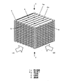
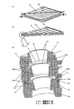
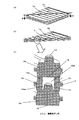
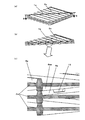
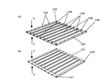
図1、図2(a)、図2(b)、図3、図4(a)、図4(b)、図4(c)において、熱交換器1aは一辺が120mmの方形で厚みが2.5mmの単位素子2aを交互に90度回転しながら積層し、支持棒3にて単位素子2a同士を結束することにより構成され、伝熱板4の間に形成された通風路5に、一次気流Aと二次気流Bを流通すると、一次気流Aと二次気流Bとは伝熱板4を介して直交しながら熱交換を行う。   1, 2 (a), 2 (b), 3, 4 (a), 4 (b), and 4 (c), the heat exchanger 1 a has a square shape with a side of 120 mm and a thickness. The 2.5 mm unit elements 2a are alternately stacked while being rotated 90 degrees, and the unit elements 2a are bound together by the support rod 3, and the ventilation path 5 formed between the heat transfer plates 4 When the primary airflow A and the secondary airflow B are circulated, the primary airflow A and the secondary airflow B exchange heat while being orthogonal to each other via the heat transfer plate 4.

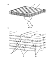
図2(a)および図2(b)の単位素子2aは、伝熱板4のX方向表面に間隔リブ6a、遮蔽リブ7a、遮蔽リブ凹部8、貫通穴9、貫通穴凸部10、積層確認凸部11、位置決め凸部12、位置決め貫通穴13a、遮蔽リブ注入口14a、間隔リブ注入口15を備え、伝熱板4のY方向表面に間隔リブ6aa、遮蔽リブ7aa、貫通穴9、位置決め貫通穴13aa、遮蔽リブ凸部16、貫通穴凹部17、積層確認凹部18、位置決め平面部19を備え、間隔リブ6a、6aaおよび遮蔽リブ7a、7aaが伝熱板4を間に挟むように、樹脂にて一体成形して得られる。   2A and 2B, the unit element 2a includes a spacing rib 6a, a shielding rib 7a, a shielding rib concave portion 8, a through hole 9, a through hole convex portion 10, and a laminated layer on the surface of the heat transfer plate 4 in the X direction. A confirmation convex portion 11, a positioning convex portion 12, a positioning through hole 13a, a shielding rib injection port 14a, a spacing rib injection port 15, and a spacing rib 6aa, a shielding rib 7aa, a through hole 9, Positioning through-hole 13aa, shielding rib convex part 16, through-hole concave part 17, stacking confirmation concave part 18 and positioning flat part 19 are provided, and spacing ribs 6a, 6aa and shielding ribs 7a, 7aa sandwich heat transfer plate 4 therebetween. , Obtained by integral molding with resin.

伝熱板4のX方向表面において、間隔リブ6aは高さ1mm、幅1mmで所定間隔に6本形成し、遮蔽リブ7aは伝熱板4の向かい合う一組の両端で間隔リブ6aと平行に高さ1mm、幅5mmに形成する。遮蔽リブ凹部8は遮蔽リブ7aの上面に、凹高さ0.5mm、幅2.5mmに通風路5に沿って凹形状に形成し、遮蔽リブ7aと遮蔽リブ凹部8の断面は階段状に形成される。遮蔽リブ注入口14aは台形状で遮蔽リブ7aと連結し、通風路5内に形成し、遮蔽リブ凹部8と同じ凸高さに形成する。貫通穴9は単位素子2aの四隅であって、遮蔽リブ7aに穴を設け、この貫通穴9の穴の周囲に凸高さ0.4mmの貫通穴凸部10を設ける。積層確認凸部11は貫通穴凸部10に連結し、方形の単位素子2aの対角する2箇所に凸高さ0.4mmで設ける。位置決め凸部12は間隔リブ6aの上面に凸高さ1.7mmで2個設け、位置決め貫通穴13aは間隔リブ6aに凸高さ1.0mmで2個の円筒を設け、間隔リブ注入口15は間隔リブ6aの上面に凹高さ0.5mmに間隔リブ6aの段を落とすような形状に形成する。   On the surface of the heat transfer plate 4 in the X direction, six spacing ribs 6a are formed at a predetermined interval with a height of 1 mm and a width of 1 mm, and the shielding ribs 7a are parallel to the spacing ribs 6a at a pair of opposite ends of the heat transfer plate 4. It is 1 mm high and 5 mm wide. The shield rib recess 8 is formed on the upper surface of the shield rib 7a to have a concave height of 0.5 mm and a width of 2.5 mm along the ventilation path 5, and the cross section of the shield rib 7a and the shield rib recess 8 is stepped. It is formed. The shielding rib inlet 14 a is trapezoidal and is connected to the shielding rib 7 a, is formed in the ventilation path 5, and has the same convex height as the shielding rib recess 8. The through holes 9 are the four corners of the unit element 2 a, and holes are provided in the shielding rib 7 a, and the through hole convex portions 10 having a convex height of 0.4 mm are provided around the through holes 9. The stacking confirmation convex portion 11 is connected to the through hole convex portion 10 and provided at two diagonal positions of the square unit element 2a with a convex height of 0.4 mm. Two positioning projections 12 are provided on the upper surface of the spacing rib 6a with a projection height of 1.7 mm, and the positioning through holes 13a are provided with two cylinders with a projection height of 1.0 mm on the spacing rib 6a. Is formed in such a shape that the step of the spacing rib 6a is dropped to a concave height of 0.5 mm on the upper surface of the spacing rib 6a.

伝熱板4のY方向表面において、間隔リブ6aaは間隔リブ6aと直交し、高さ1mm、幅1mmで所定間隔に6本形成し、遮蔽リブ7aaは伝熱板4の向かい合う一組の両端で間隔リブ6aaと平行に高さ1mm、幅5mmに形成する。遮蔽リブ凸部16は遮蔽リブ7aaの上面に、凸高さ0.4mm、幅2.4mmに通風路5に沿って凸形状に形成し、遮蔽リブ7aaと遮蔽リブ凸部16の断面は階段状に形成される。貫通穴9は単位素子2aの四隅であって、遮蔽リブ7aaに穴を設け、この貫通穴9の穴の周囲に凹高さ0.5mmの貫通穴凹部17を設ける。積層確認凹部18は貫通穴凹部17に連結し、方形の単位素子2aの対角する2箇所に凹高さ0.5mmで設ける。位置決め平面部19は伝熱板4を挟んで位置決め凸部12の反対側に凸高さ1.0mmの円柱を2箇所設け、位置決め貫通穴13aaは伝熱板4を挟んで位置決め貫通穴13aの反対側に凸高さ1.0mmで2個の円筒を設ける。   On the surface in the Y direction of the heat transfer plate 4, the interval ribs 6 aa are orthogonal to the interval ribs 6 a, and are formed at a predetermined interval with a height of 1 mm and a width of 1 mm, and the shielding ribs 7 aa are a pair of opposite ends of the heat transfer plate 4. Thus, the height is 1 mm and the width is 5 mm in parallel with the spacing rib 6aa. The shielding rib convex portion 16 is formed on the upper surface of the shielding rib 7aa in a convex shape along the ventilation path 5 with a convex height of 0.4 mm and a width of 2.4 mm. The cross section of the shielding rib 7aa and the shielding rib convex portion 16 is a staircase. It is formed in a shape. The through holes 9 are the four corners of the unit element 2 a, and holes are provided in the shielding rib 7 aa, and a through hole concave portion 17 having a concave height of 0.5 mm is provided around the through hole 9. The stacking confirmation recesses 18 are connected to the through-hole recesses 17 and provided at two opposite corners of the rectangular unit element 2a with a recess height of 0.5 mm. The positioning flat surface portion 19 is provided with two columns having a convex height of 1.0 mm on the opposite side of the positioning convex portion 12 with the heat transfer plate 4 interposed therebetween, and the positioning through hole 13aa is located between the positioning heat transfer plate 4 and the positioning through hole 13a. Two cylinders with a convex height of 1.0 mm are provided on the opposite side.

図4(a)、図4(b)、図4(c)に示すように、間隔リブ6aと間隔リブ6aaは単位素子2aを交互に90度回転しながら積層した時に、隣接する間隔リブ6aと間隔リブ6aaが重なり合うように形成され、伝熱板4を一定の間隔に保持する働がある。本実施の形態では、間隔リブ6aおよび間隔リブ6aaの凸高さを1mmとしたので、伝熱板4は2mm毎に積層される。   As shown in FIG. 4A, FIG. 4B, and FIG. 4C, the spacing rib 6a and the spacing rib 6aa are adjacent to each other when the unit elements 2a are stacked while being alternately rotated by 90 degrees. And the spacing ribs 6aa are formed so as to overlap each other, and serves to hold the heat transfer plate 4 at a constant spacing. In the present embodiment, since the convex height of the spacing rib 6a and the spacing rib 6aa is 1 mm, the heat transfer plate 4 is laminated every 2 mm.

図4(a)、図4(b)、図4(c)に示すように、遮蔽リブ7aと遮蔽リブ7aaは単位素子2aを交互に90度回転しながら積層した時に、隣接する遮蔽リブ7aと遮蔽リブ7aaが重なり合うように形成され、熱交換器1aの通風路5を流通する一次気流Aおよび二次気流Bが熱交換器1aの端面から気流が漏れないように遮蔽する働きと、伝熱板4を一定の間隔に保持する働きがある。   As shown in FIGS. 4 (a), 4 (b), and 4 (c), the shielding ribs 7a and the shielding ribs 7aa are adjacent to each other when the unit elements 2a are stacked while being alternately rotated by 90 degrees. And the shielding rib 7aa are overlapped, and the primary air flow A and the secondary air flow B flowing through the ventilation path 5 of the heat exchanger 1a are shielded so that the air flow does not leak from the end face of the heat exchanger 1a, and It has the function of holding the hot plate 4 at a constant interval.

なお遮蔽リブ7a、7aaは熱交換器1aの伝熱板4を一定容積内で広く取るために、方形の単位素子2aの両端部に形成する構成としたが、熱交換器の設計や量産性などにより適宜決定する。   The shielding ribs 7a and 7aa are configured to be formed at both ends of the rectangular unit element 2a so that the heat transfer plate 4 of the heat exchanger 1a is wide within a certain volume. However, the design and mass productivity of the heat exchanger are not provided. It is determined as appropriate.

図4(a)、図4(b)、図4(c)に示すように、遮蔽リブ凹部8と遮蔽リブ凸部16は単位素子2aを交互に90度回転しながら正しく積層した時には、隣接する遮蔽リブ凹部8の凹部と遮蔽リブ凸部16の凸部が嵌合するよう形成される。熱交換器1aは遮蔽リブ7aおよび遮蔽リブ7aaに設けた遮蔽リブ凹部8と遮蔽リブ凸部16の嵌合により、単位素子2a同士が互いに固定化され、且つ単位素子2aを積層する際に発生する位置ずれを防止する。熱交換器1aの側面における気流の遮蔽は、図4(c)に示すように隣接する遮蔽リブ7aおよび遮蔽リブ7aa同士が重なり合うことにより行われ、遮蔽リブ凹部8の凹部と遮蔽リブ凸部16の凸部の嵌合も気流の遮蔽を行う。本実施の形態では、金型の製造精度と樹脂成形の精度を考慮して、遮蔽リブ7aおよび遮蔽リブ7aaは必ず重なり合うようにし、遮蔽リブ凹部8と遮蔽リブ凸部16の嵌合は、気流が漏れない程度に高さ方向に0.1mmの積層逃がし部20aを設けた。なお0.1mmの高さ方向の積層逃がし部20aを設けたが、単位素子2aを正しく積層した時には、熱交換器1aの側面における気流の遮蔽と単位素子2a同士の嵌合ができれば良く、熱交換器の設計や製造精度により適宜決定する。   As shown in FIGS. 4 (a), 4 (b), and 4 (c), the shielding rib recesses 8 and the shielding rib projections 16 are adjacent to each other when the unit elements 2a are properly stacked while rotating 90 degrees alternately. The concave portion of the shielding rib concave portion 8 and the convex portion of the shielding rib convex portion 16 are formed to be fitted. The heat exchanger 1a is generated when the unit elements 2a are fixed to each other by stacking the unit elements 2a by fitting the shielding ribs 7a and the shielding rib concave parts 8 provided on the shielding ribs 7aa and the shielding rib convex parts 16 together. To prevent misalignment. The airflow shielding on the side surface of the heat exchanger 1a is performed by overlapping the adjacent shielding ribs 7a and the shielding ribs 7aa as shown in FIG. The fitting of the protrusions also shields the airflow. In the present embodiment, in consideration of the manufacturing accuracy of the mold and the accuracy of resin molding, the shielding rib 7a and the shielding rib 7aa are necessarily overlapped, and the fitting of the shielding rib concave portion 8 and the shielding rib convex portion 16 is an air flow. Is provided with a stacking relief portion 20a of 0.1 mm in the height direction so as not to leak. Although the stacking relief part 20a in the height direction of 0.1 mm is provided, when the unit elements 2a are correctly stacked, it is only necessary to shield the air flow on the side surface of the heat exchanger 1a and fit the unit elements 2a to each other. It is determined appropriately according to the design and manufacturing accuracy of the exchanger.

図5(a)、図5(b)に示すように、単位素子2aを交互に90度回転せず、誤って積層した時には、遮蔽リブ凸部16の凸部は隣接する間隔リブ6aと干渉し、隣接する単位素子2a同士が嵌合できず、熱交換器1aの側面から確認すると単位素子2a同士に隙間があり、容易に単位素子2aの積み間違いを確認することができる構成となっている。   As shown in FIG. 5A and FIG. 5B, when the unit elements 2a are not rotated alternately by 90 degrees and are stacked by mistake, the projections of the shielding rib projections 16 interfere with the adjacent spacing ribs 6a. However, the adjacent unit elements 2a cannot be fitted to each other, and when confirmed from the side surface of the heat exchanger 1a, there is a gap between the unit elements 2a, so that it is possible to easily confirm a stacking error of the unit elements 2a. Yes.

なお遮蔽リブ凹部8および遮蔽リブ凸部16は単位素子2aの遮蔽リブ7aおよび遮蔽リブ7aaに設けたが、単位素子を正しく積層した時には隣接する単位素子の凹部と凸部が嵌合し、誤って積層した時には凸部と隣接する単位素子の一部が干渉する構造であれば、その他の構成の熱交換器を用いても同様の作用効果を得ることができる。   The shield rib recess 8 and the shield rib protrusion 16 are provided on the shield rib 7a and the shield rib 7aa of the unit element 2a. However, when the unit elements are correctly stacked, the recesses and the projections of the adjacent unit elements are fitted to each other. As long as a part of the unit element adjacent to the convex portion interferes when stacked, the same effect can be obtained even if a heat exchanger having another configuration is used.

この明細書における干渉とは、単位素子2aを誤って積層した時に凸部と隣接する単位素子2aの一部が当たり、隣接する単位素子2a同士が嵌合できず隙間ができる状態のことである。また、単位素子2aを正しく積層するとは、単位素子2aに備えた凹部と凸部の嵌合構造が互いに嵌合し、気流の漏れが無く、熱交換器の基本性能が発揮できる状態のことであり、単位素子2aを誤って積層するとは、単位素子2aに備えた凸部と単位素子2aの一部が干渉し、隣接する単位素子2aの間に隙間ができ、気流の漏れが有り、熱交換器の基本性能が発揮できない状態のことである。   The interference in this specification is a state in which when the unit elements 2a are mistakenly stacked, a part of the unit elements 2a adjacent to the convex portion hits, and the adjacent unit elements 2a cannot be fitted to each other and a gap is formed. . In addition, when the unit elements 2a are correctly laminated, the concave and convex fitting structures provided in the unit elements 2a are fitted to each other, there is no airflow leakage, and the basic performance of the heat exchanger can be exhibited. Yes, if the unit elements 2a are mistakenly stacked, the convex portions provided in the unit elements 2a and a part of the unit elements 2a interfere with each other, a gap is formed between the adjacent unit elements 2a, airflow is leaked, This means that the basic performance of the exchanger cannot be demonstrated.

図6(a)、図6(b)、図6(c)に示すように、貫通穴凹部17と貫通穴凸部10は単位素子2aを交互に90度回転しながら正しく積層した時には、隣接する貫通穴凹部17の凹部と貫通穴凸部10の凸部が嵌合するよう形成される。熱交換器1aは単位素子2aの四隅に設けた貫通穴凹部17と貫通穴凸部10の嵌合により、単位素子2a同士が互いに固定化され、且つ単位素子2aを積層する際に発生する位置ずれを防止する。熱交換器1aの四隅における気流の遮蔽は、図6(c)に示すように隣接する遮蔽リブ7aおよび遮蔽リブ7aa同士が重なり合うことにより行われ、貫通穴凹部17の凹部と貫通穴凸部10の凸部の嵌合も気流の遮蔽を行う。この明細書では、金型の製造精度と樹脂成形の精度を考慮して、遮蔽リブ7aおよび遮蔽リブ7aaは必ず重なり合うようにし、貫通穴凹部17と貫通穴凸部10の嵌合は、気流が漏れない程度に高さ方向に0.1mmの積層逃がし部20bを設けた。   As shown in FIGS. 6 (a), 6 (b), and 6 (c), the through-hole recesses 17 and the through-hole protrusions 10 are adjacent when the unit elements 2a are correctly stacked while alternately rotating 90 degrees. The concave portion of the through-hole concave portion 17 and the convex portion of the through-hole convex portion 10 are formed to be fitted. The heat exchanger 1a is a position generated when the unit elements 2a are stacked and the unit elements 2a are stacked by fitting the through-hole concave portions 17 and the through-hole convex portions 10 provided at the four corners of the unit elements 2a. Prevent misalignment. Airflow shielding at the four corners of the heat exchanger 1a is performed by overlapping the adjacent shielding ribs 7a and the shielding ribs 7aa as shown in FIG. The fitting of the protrusions also shields the airflow. In this specification, in consideration of the manufacturing accuracy of the mold and the accuracy of resin molding, the shielding rib 7a and the shielding rib 7aa are necessarily overlapped. A stacking relief portion 20b of 0.1 mm was provided in the height direction so as not to leak.

なお0.1mmの高さ方向の積層逃がし部20bを設けたが、単位素子2aを正しく積層した時には、熱交換器1aの四隅における気流の遮蔽と単位素子2a同士の嵌合ができれば良く、熱交換器の設計や製造精度により適宜決定する。   Although the stacking relief part 20b in the height direction of 0.1 mm is provided, when the unit elements 2a are correctly stacked, it is only necessary to shield the air flow at the four corners of the heat exchanger 1a and fit the unit elements 2a to each other. It is determined appropriately according to the design and manufacturing accuracy of the exchanger.

なお貫通穴凹部17および貫通穴凸部10は単位素子2aの単位素子2aの四隅に設けたが、単位素子を正しく積層した時には隣接する単位素子の凹部と凸部が嵌合し、間隔リブまたは遮蔽リブの少なくとも何れか、または間隔リブまたは遮蔽リブの少なくとも何れかに連結する構造であれば、その他の構成の熱交換器を用いても同様の作用効果を得ることができる。   The through-hole concave portion 17 and the through-hole convex portion 10 are provided at the four corners of the unit element 2a of the unit element 2a. However, when the unit elements are correctly stacked, the concave and convex portions of the adjacent unit elements are fitted, As long as the structure is connected to at least one of the shielding ribs, or at least one of the spacing ribs and the shielding ribs, the same operation and effect can be obtained even if a heat exchanger having another configuration is used.

また、図6(a)、図6(b)、図6(c)に示すように、積層確認凹部18と積層確認凸部11は単位素子2aを交互に90度回転しながら正しく積層した時には、隣接する積層確認凹部18の凹部と積層確認凸部11の凸部が嵌合するよう形成される。熱交換器1aは方形の単位素子2aの対角する2箇所に設けた積層確認凹部18と積層確認凸部11の嵌合により、単位素子2a同士が互いに固定化され、且つ単位素子2aを積層する際に発生する位置ずれを防止する。熱交換器1aの四隅における気流の遮蔽は、図6(c)に示すように隣接する遮蔽リブ7aおよび遮蔽リブ7aa同士が重なり合うことにより行われ、積層確認凹部18の凹部と積層確認凸部11の凸部の嵌合も気流の遮蔽を行う。この明細書では、金型の製造精度と樹脂成形の精度を考慮して、遮蔽リブ7aおよび遮蔽リブ7aaは必ず重なり合うようにし、積層確認凹部18と積層確認凸部11の嵌合は、気流が漏れない程度に高さ方向に0.1mmの積層逃がし部20cを設けた。   Further, as shown in FIGS. 6A, 6B, and 6C, when the stacking confirmation concave portion 18 and the stacking confirmation convex portion 11 are correctly stacked while alternately rotating the unit elements 2a by 90 degrees. The concave portions of the adjacent stacking confirmation concave portions 18 and the convex portions of the stacking confirmation convex portions 11 are formed so as to be fitted. In the heat exchanger 1a, the unit elements 2a are fixed to each other and the unit elements 2a are stacked by fitting the stacking confirmation concave portions 18 and the stacking confirmation convex portions 11 provided at two diagonal positions of the square unit element 2a. This prevents misalignment that occurs when Airflow shielding at the four corners of the heat exchanger 1a is performed by overlapping the adjacent shielding ribs 7a and the shielding ribs 7aa as shown in FIG. The fitting of the protrusions also shields the airflow. In this specification, considering the manufacturing accuracy of the mold and the accuracy of resin molding, the shielding rib 7a and the shielding rib 7aa are always overlapped, and the fitting of the stacking confirmation concave portion 18 and the stacking confirmation convex portion 11 is caused by an air flow. A stacking relief portion 20c of 0.1 mm was provided in the height direction so as not to leak.

なお0.1mmの高さ方向の積層逃がし部20cを設けたが、単位素子2aを正しく積層した時には、熱交換器1aの四隅における気流の遮蔽と単位素子2a同士の嵌合ができれば良く、熱交換器の設計や製造精度により適宜決定する。   Although the stacking relief portion 20c in the height direction of 0.1 mm is provided, when the unit elements 2a are correctly stacked, it is only necessary to shield the airflow at the four corners of the heat exchanger 1a and fit the unit elements 2a to each other. It is determined appropriately according to the design and manufacturing accuracy of the exchanger.

図7(a)、図7(b)、図7(c)に示すように、単位素子2aを交互に90度回転せず、誤って積層した時には、積層確認凸部11の凸部は隣接する遮蔽リブ7aaと干渉し、隣接する単位素子2a同士が嵌合できず、熱交換器1aの側面から確認すると単位素子2a同士に隙間があり、容易に単位素子2aの積み間違いを確認することができる構成となっている。   As shown in FIG. 7A, FIG. 7B, and FIG. 7C, when the unit elements 2a are not rotated alternately by 90 degrees and are stacked incorrectly, the protrusions of the stacking confirmation protrusion 11 are adjacent to each other. The adjacent unit elements 2a cannot be fitted to each other due to interference with the shielding rib 7aa, and when confirmed from the side surface of the heat exchanger 1a, there is a gap between the unit elements 2a, and the unit element 2a can be easily checked for stacking errors. It has a configuration that can.

なお積層確認凹部18および積層確認凸部11は単位素子2aの対角にそれぞれ2個設けたが、単位素子を正しく積層した時には隣接する単位素子の凹部と凸部が嵌合し、誤って積層した時には凸部と隣接する単位素子の一部が干渉する構造であれば、その他の構成の熱交換器を用いても同様の作用効果を得ることができる。   Although the stacking confirmation recess 18 and the stacking confirmation protrusion 11 are provided at two diagonals of the unit element 2a, when the unit elements are correctly stacked, the recesses and the projections of the adjacent unit elements are fitted to each other and the stacking is erroneously performed. In this case, if the structure is such that a part of the unit element adjacent to the convex portion interferes, the same operation and effect can be obtained even if a heat exchanger having another configuration is used.

図8に示す伝熱板4は一辺が119mmの方形で、厚さが0.2〜0.01mm、好ましくは0.1〜0.01mmの和紙、防燃紙、伝熱性と透湿性と気体遮蔽性を有する特殊加工紙、透湿膜、または伝熱性のみを有するポリエステル系、ポリスチレン系のABS、AS、PS、ポリオレフィン系のPP、PEなどの樹脂シート、樹脂フィルムなどで構成される。伝熱板4の四隅には貫通穴9を4個設け、方形の伝熱板4の一つの対角線上に位置決め穴21を2個設け、この伝熱板4を樹脂金型に挿入し、インサート射出成形を用いて単位素子2aを一体成形する。伝熱板4を樹脂金型内に挿入する際、伝熱板4を位置決め、固定するためのピンを樹脂金型に設けておき、樹脂金型のピンと伝熱板4の位置決め穴21によって伝熱板4の位置決めを行う。   The heat transfer plate 4 shown in FIG. 8 has a rectangular shape with a side of 119 mm and a thickness of 0.2 to 0.01 mm, preferably 0.1 to 0.01 mm, Japanese paper, flameproof paper, heat transfer, moisture permeability, and gas. It is composed of a specially processed paper having a shielding property, a moisture permeable film, or a resin sheet such as polyester, polystyrene, ABS, AS, PS, polyolefin PP or PE having only heat conductivity, a resin film, or the like. Four through-holes 9 are provided at the four corners of the heat transfer plate 4, two positioning holes 21 are provided on one diagonal line of the square heat transfer plate 4, and the heat transfer plate 4 is inserted into a resin mold. The unit element 2a is integrally formed using injection molding. When the heat transfer plate 4 is inserted into the resin mold, a pin for positioning and fixing the heat transfer plate 4 is provided in the resin mold, and the heat transfer plate 4 and the positioning hole 21 of the heat transfer plate 4 are used to transfer the heat transfer plate 4. The hot plate 4 is positioned.

図9(a)、図9(b)、図9(c)に示すように、位置決め貫通穴13a、13aaは伝熱板4の位置決め穴21の周囲に形成され、位置決め凸部12の凸部は単位素子2aを交互に90度回転しながら正しく積層した時には、隣接する位置決め貫通穴13a、13aaと嵌合するように形成され、位置決め平面部19は隣接する位置決め貫通穴13aの穴を塞ぐように形成される。   9 (a), 9 (b), and 9 (c), the positioning through holes 13a and 13aa are formed around the positioning hole 21 of the heat transfer plate 4, and the convex portion of the positioning convex portion 12 is formed. Is formed so that the unit elements 2a are correctly stacked while being alternately rotated by 90 degrees, so that they are fitted to the adjacent positioning through-holes 13a, 13aa, and the positioning flat portion 19 closes the holes of the adjacent positioning through-holes 13a. Formed.

熱交換器1aは単位素子2aの対角線上に設けた位置決め貫通穴13a、13aaと位置決め凸部12の嵌合により、単位素子2a同士が互いに固定化され、且つ単位素子2aを積層する際に発生する位置ずれを防止する。熱交換器1aの中央部における気流の遮蔽は、図9(c)に示すように隣接する位置決め平面部19と位置決め貫通穴13aおよび位置決め凸部12の凸部下面と位置決め貫通穴13aaが重なり合うことにより行われ、位置決め貫通穴13a、13aaの穴と位置決め凸部12の凸部の嵌合も気流の遮蔽を行う。この明細書では、金型の製造精度と樹脂成形の精度を考慮して、位置決め平面部19と位置決め貫通穴13aおよび位置決め凸部12の凸部下面と位置決め貫通穴13aaは必ず重なり合うようにし、位置決め貫通穴13a、13aaと位置決め凸部12の嵌合は、気流が漏れない程度に高さ方向に0.3mmの積層逃がし部20dを設けた。なお0.3mmの高さ方向の積層逃がし部20dを設けたが、単位素子2aを正しく積層した時には、熱交換器1aの中央部における気流の遮蔽と単位素子2a同士の嵌合ができれば良く、熱交換器の設計や製造精度により適宜決定する。   The heat exchanger 1a occurs when the unit elements 2a are fixed to each other by stacking the unit elements 2a by fitting the positioning through holes 13a, 13aa provided on the diagonal line of the unit elements 2a and the positioning projections 12 to each other. To prevent misalignment. As shown in FIG. 9C, the airflow shielding at the central portion of the heat exchanger 1a is such that the adjacent positioning flat surface portion 19 and positioning through hole 13a and the bottom surface of the positioning convex portion 12 overlap the positioning through hole 13aa. The fitting of the positioning through holes 13a and 13aa and the convex portions of the positioning convex portion 12 also shields the airflow. In this specification, in consideration of mold manufacturing accuracy and resin molding accuracy, the positioning flat surface portion 19 and the positioning through-hole 13a and the lower surface of the positioning convex portion 12 and the positioning through-hole 13aa are always overlapped, The through holes 13a, 13aa and the positioning convex portion 12 were fitted with a 0.3 mm laminated escape portion 20d in the height direction so as not to leak airflow. Although the stacking relief part 20d in the height direction of 0.3 mm is provided, when the unit elements 2a are correctly stacked, it is only necessary to shield the air flow at the center of the heat exchanger 1a and to fit the unit elements 2a, It is determined as appropriate according to the design and manufacturing accuracy of the heat exchanger.

図10(a)、図10(b)、図10(c)に示すように、単位素子2aを交互に90度回転せず、誤って積層した時には、位置決め凸部12の凸部は隣接する位置決め平面部19と干渉し、隣接する単位素子2a同士が嵌合できず、熱交換器1aの側面から確認すると単位素子2a同士に隙間があり、容易に単位素子2aの積み間違いを確認することができる構成となっている。   As shown in FIGS. 10 (a), 10 (b), and 10 (c), when the unit elements 2a are not alternately rotated by 90 degrees and are stacked incorrectly, the protrusions of the positioning protrusions 12 are adjacent to each other. Interfering with the positioning flat surface portion 19, the adjacent unit elements 2a cannot be fitted to each other, and when confirmed from the side surface of the heat exchanger 1a, there is a gap between the unit elements 2a. It has a configuration that can.

なお、位置決め貫通穴13a、13aa、位置決め凸部12および位置決め平面部19は単位素子2aの対角線上にそれぞれ2個設けたが、単位素子を正しく積層した時には隣接する単位素子の穴と凸部が嵌合し、誤って積層した時には凸部と隣接する単位素子の一部が干渉する構造であれば、その他の構成の熱交換器を用いても同様の作用効果を得ることができる。   The positioning through-holes 13a, 13aa, the positioning convex portion 12 and the positioning flat portion 19 are each provided on the diagonal of the unit element 2a. However, when the unit elements are correctly stacked, the holes and convex portions of the adjacent unit elements are not formed. Similar effects can be obtained even if heat exchangers with other configurations are used as long as they have a structure in which a part of the unit element adjacent to the convex portion interferes when they are fitted and mistakenly stacked.

図6(c)と図8に示すように、伝熱板4と樹脂を一体成形して形成された単位素子2aにおいて、伝熱板4の貫通穴9は遮蔽リブ7a、7aaの貫通穴9と同じ位置で、単位素子2aに貫通する穴が形成され、この穴の周囲に貫通穴凸部10および貫通穴凹部17が形成される。   As shown in FIGS. 6C and 8, in the unit element 2a formed by integrally molding the heat transfer plate 4 and the resin, the through holes 9 of the heat transfer plate 4 are the through holes 9 of the shielding ribs 7a and 7aa. A hole penetrating the unit element 2a is formed at the same position, and the through hole convex portion 10 and the through hole concave portion 17 are formed around the hole.

図6(c)と図9(c)に示すように、貫通穴9、貫通穴凸部10および貫通穴凹部17は遮蔽リブ7a、7aaに連結する位置に構成し、位置決め貫通穴13a、13aa、位置決め凸部12および位置決め平面部19は間隔リブ6a、6aaに連結する位置に構成しているため、一回の樹脂成形でこれらを有する単位素子2aが形成できる。   As shown in FIGS. 6 (c) and 9 (c), the through hole 9, the through hole convex portion 10 and the through hole concave portion 17 are configured to be connected to the shielding ribs 7a and 7aa, and the positioning through holes 13a and 13aa. Since the positioning convex portion 12 and the positioning flat surface portion 19 are configured to be connected to the spacing ribs 6a and 6aa, the unit element 2a having them can be formed by a single resin molding.

なお、貫通穴9、貫通穴凸部10および貫通穴凹部17は遮蔽リブ7a、7aaに連結する位置に形成し、位置決め貫通穴13a、13aa、位置決め凸部12および位置決め平面部19は間隔リブ6a、6aaに連結する位置に形成したが、貫通穴9、貫通穴凸部10、貫通穴凹部17、位置決め貫通穴13a、13aa、位置決め凸部12および位置決め平面部19は間隔リブ6a、6aaまたは遮蔽リブ7a、7aaの少なくとも何れか、または間隔リブ6a、6aaまたは遮蔽リブ7a、7aaの少なくとも何れかに連結する位置に設け、伝熱板4と樹脂を一体成形して単位素子2aを得る際に、一回の樹脂成形で一体に形成できれば良く、その他の構成を用いても同様の作用効果を得ることができる。   The through-hole 9, the through-hole convex portion 10 and the through-hole concave portion 17 are formed at positions where they are connected to the shielding ribs 7a and 7aa, and the positioning through-holes 13a and 13aa, the positioning convex portion 12 and the positioning flat portion 19 are the spacing ribs 6a. The through holes 9, the through hole convex portions 10, the through hole concave portions 17, the positioning through holes 13a, 13aa, the positioning convex portions 12 and the positioning flat portions 19 are spaced ribs 6a, 6aa or shielded. When the unit element 2a is obtained by integrally forming the heat transfer plate 4 and the resin, provided at a position connected to at least one of the ribs 7a, 7aa, or at least one of the spacing ribs 6a, 6aa or the shielding ribs 7a, 7aa. It is sufficient if they can be integrally formed by a single resin molding, and similar effects can be obtained even if other configurations are used.

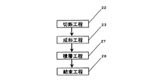
図11と図12に熱交換器1aの製造工程および製造方法を示す。切断工程22は伝熱板4を所定の大きさに切断する。   11 and 12 show a manufacturing process and a manufacturing method of the heat exchanger 1a. The cutting step 22 cuts the heat transfer plate 4 into a predetermined size.

次の成形工程23は伝熱板4を射出成形金型24に挿入し、射出成形機にて伝熱板4と樹脂を一体成形するインサート射出成形工法で単位素子2aが得られる。この樹脂としては熱可塑性樹脂を適用し、樹脂の種類としては、ポリエステル系、ポリスチレン系のABS、AS、PS、またはポリオレフィン系のPP、PEなどが用いられる。また熱可塑性樹脂の中にガラス繊維または炭素繊維の無機充填剤を添加した樹脂を用いても良い。無機充填剤の添加量は樹脂の重量に対して1〜50重量%、更に好ましくは10〜30重量%であり、樹脂に無機充填剤を添加すると、樹脂成形品の単位素子2aは強度と反りや収縮性の物性が向上することと、一体成形する伝熱板4と樹脂との接着性が向上する。これは化学結合による接着性が向上するのではなく、無機充填剤と伝熱板4との繊維の絡まりが強くなった物理結合が向上するものである。   In the next molding step 23, the unit element 2a is obtained by an insert injection molding method in which the heat transfer plate 4 is inserted into the injection mold 24 and the heat transfer plate 4 and the resin are integrally formed by an injection molding machine. As this resin, a thermoplastic resin is applied. As the type of resin, polyester-based, polystyrene-based ABS, AS, PS, polyolefin-based PP, PE, or the like is used. Further, a resin obtained by adding an inorganic filler of glass fiber or carbon fiber to a thermoplastic resin may be used. The addition amount of the inorganic filler is 1 to 50% by weight, more preferably 10 to 30% by weight with respect to the weight of the resin. When the inorganic filler is added to the resin, the unit element 2a of the resin molded product has strength and warpage. In addition, the shrinkable physical properties are improved, and the adhesion between the heat transfer plate 4 and the resin to be integrally molded is improved. This does not improve the adhesiveness due to the chemical bond, but improves the physical bond in which the fiber entanglement between the inorganic filler and the heat transfer plate 4 becomes strong.

無機充填剤の添加量は樹脂の重量に対して多く混入すると、樹脂成形品の強度と反りや収縮性の物性が向上するが、50重量%以上になると、射出成形する時の溶融した樹脂の流動性が低下するため、樹脂成形品が得られない場合があり、無機充填剤の添加量は樹脂成形品の必要強度、樹脂物性、射出成形機の仕様などにより適宜決定する。   If a large amount of the inorganic filler is added relative to the weight of the resin, the strength, warpage and shrinkage properties of the resin molded product will be improved. Since the fluidity decreases, a resin molded product may not be obtained, and the amount of the inorganic filler added is appropriately determined depending on the required strength of the resin molded product, the physical properties of the resin, the specifications of the injection molding machine, and the like.

この成形工程23は、溶融した樹脂を伝熱板4のX方向からから射出成形金型24内に射出すると、樹脂流路を通り、金型のゲート部から単位素子2aに設けた遮蔽リブ注入口14aおよび間隔リブ注入口15から流入し、更に溶融した樹脂は射出圧力が高いため、伝熱板4のX方向表面の間隔リブ6aおよび遮蔽リブ7aを成形すると共に、和紙などの紙類で構成された伝熱板4を貫通し、伝熱板4Y方向表面の間隔リブ6aaおよび遮蔽リブ7aaと連結する形で形成することができるので、一回の成形で伝熱板4と間隔リブ6a、6aaと遮蔽リブ7a、7aaを有する単位素子2aを形成することができる。   In this molding step 23, when the molten resin is injected from the X direction of the heat transfer plate 4 into the injection mold 24, it passes through the resin flow path and the shielding rib provided on the unit element 2a from the gate portion of the mold. Since the molten resin flowing in from the inlet 14a and the spacing rib inlet 15 has a high injection pressure, the spacing rib 6a and the shielding rib 7a on the surface in the X direction of the heat transfer plate 4 are formed, and paper such as Japanese paper is used. Since the heat transfer plate 4 can be formed so as to penetrate the configured heat transfer plate 4 and be connected to the spacing rib 6aa and the shielding rib 7aa on the surface of the heat transfer plate 4Y, the heat transfer plate 4 and the spacing rib 6a can be formed by a single molding. , 6aa and the shielding ribs 7a, 7aa, the unit element 2a can be formed.

単位素子2aを樹脂成形する射出成形金型24はランナーレスにする手段を備え、ランナーレスにする手段として、オープンゲート式またはバルブゲート式のホットランナーを使用する。ヒータ25によりランナー・ゲート部を加熱制御して溶融樹脂を常に流動化状態に保てるため、樹脂成形時に廃材となるスプル・ランナー26が出ず、樹脂材料費削減と省資源化することができる。また成形品の単位素子2aのみを射出成形金型24から連続的に取り出せるので成形サイクルを短縮することができる。   The injection mold 24 for resin-molding the unit element 2a includes a runner-less means, and an open-gate or valve-gate hot runner is used as a runner-less means. Since the molten resin can always be kept fluidized by controlling the runner / gate portion with the heater 25, the sprue runner 26 which becomes a waste material at the time of resin molding does not come out, and the resin material cost can be reduced and the resources can be saved. Further, since only the unit element 2a of the molded product can be continuously taken out from the injection mold 24, the molding cycle can be shortened.

この明細書のスプルとは、射出成形金型24において成形材料の流路の一部で円錐形の部分を指し、ランナーとは射出成形金型24においてキャビティに溶融樹脂を流し込む径路のうち、スプルからゲートまでの部分を指す。   The sprue in this specification refers to a conical part of the flow path of the molding material in the injection mold 24, and the runner refers to the sprue of the paths through which molten resin flows into the cavity in the injection mold 24. The part from the gate to the gate.

またバルブゲート式のホットランナーはゲート開閉機能を有するので、溶融樹脂が射出成形金型24から注入される単位素子2aの遮蔽リブ注入口14aおよび間隔リブ注入口15においてバリができないため、単位素子2aを積層した際に隣接する単位素子2a同士がバリによって干渉することがなく、隙間無く単位素子2aを積層することができる。   Further, since the valve gate type hot runner has a gate opening / closing function, the burr cannot be formed at the shielding rib injection port 14a and the interval rib injection port 15 of the unit element 2a into which the molten resin is injected from the injection mold 24. When the 2a is stacked, the adjacent unit elements 2a do not interfere with each other by burrs, and the unit elements 2a can be stacked without any gap.

次の積層工程27は単位素子2aを交互に90度回転しながら積層し、単位素子2aの四隅に設けた貫通穴9に支持棒3を挿入する工程である。   The next laminating step 27 is a step of laminating the unit elements 2a while alternately rotating by 90 degrees, and inserting the support bars 3 into the through holes 9 provided at the four corners of the unit elements 2a.

次の結束工程28は貫通穴9に挿入した支持棒3の両端に止め具を付設し単位素子2a同士を結束することによって熱交換器1aを得る工程である。また、支持棒3は熱可塑性樹脂などよりなるものであって、支持棒3の両端を熱によって溶融し単位素子2a同士を締め付けた状態で固化させることにより結束するものであってもよい。なお本発明における結束とは、単位素子2a同士を機械的拘束により固定化したものである。   The next bundling step 28 is a step of obtaining the heat exchanger 1a by attaching a stopper to both ends of the support rod 3 inserted into the through hole 9 and bundling the unit elements 2a. The support rod 3 may be made of a thermoplastic resin or the like, and may be bound by melting both ends of the support rod 3 with heat and solidifying the unit elements 2a in a clamped state. The term “bundling” in the present invention means that the unit elements 2a are fixed by mechanical restraint.

熱交換器1aは間隔リブ6aおよび遮蔽リブ7aに連結する位置に溶融樹脂を注入する遮蔽リブ注入口14aおよび間隔リブ注入口15を備え、間隔リブ6a、6aaおよび遮蔽リブ7a、7aaが何れかで連結している構成である。また遮蔽リブ注入口14aおよび間隔リブ注入口15は、単位素子2aを積層した時に隣接する単位素子2aが干渉しないように逃がす手段を備え、逃がす手段として、間隔リブ6aおよび遮蔽リブ7aに段落としを設ける。また段落としとして遮蔽リブ7aに連結し、通風路5内に遮蔽リブ注入口14aを設ける。   The heat exchanger 1a includes a shielding rib injection port 14a for injecting molten resin at a position connected to the spacing rib 6a and the shielding rib 7a and a spacing rib injection port 15, and any one of the spacing ribs 6a, 6aa and the shielding ribs 7a, 7aa. It is the structure connected with. Further, the shielding rib injection port 14a and the spacing rib injection port 15 are provided with means for allowing the adjacent unit elements 2a to avoid interference when the unit elements 2a are stacked, and the spacing rib 6a and the shielding rib 7a are provided as a paragraph as a means for releasing. Is provided. Further, as a paragraph, it is connected to the shielding rib 7 a and a shielding rib inlet 14 a is provided in the ventilation path 5.

図4(a)、図4(b)、図4(c)に示すように、遮蔽リブ注入口14aは通風路5内に段落としを設けたことにより、溶融樹脂が金型から注入される遮蔽リブ注入口14aにおいてバリが万一発生しても、単位素子2aを積層した際に隣接する単位素子2a同士は段落しによってバリを逃がすことにより干渉せず、更に前記バリは通風路5内に位置するため、隣接する単位素子2aとの通風路5空間によってバリを逃がすことにより更に干渉せず、隙間無く単位素子2aを積層することができる。   As shown in FIGS. 4 (a), 4 (b), and 4 (c), the shielding rib injection port 14a is provided with a paragraph in the ventilation path 5, so that the molten resin is injected from the mold. Even if burrs occur in the shielding rib inlet 14a, the adjacent unit elements 2a do not interfere with each other when the unit elements 2a are stacked, and the burrs do not interfere with each other in the ventilation path 5. Therefore, it is possible to stack the unit elements 2a without any gap without causing further interference by releasing the burr by the space of the ventilation path 5 between the adjacent unit elements 2a.

図13(a)、図13(b)、図13(c)に示すように、間隔リブ6aに設けた間隔リブ注入口15は単位素子2aを交互に90度回転しながら正しく積層した時には、隣接する間隔リブ6aaと重なり合うが、間隔リブ注入口15は間隔リブ6aの上面に凹高さ0.5mmに間隔リブ6aを段落しするような形状のため、溶融樹脂が金型から注入される間隔リブ注入口15においてバリが万一発生しても、単位素子2aを積層した際に隣接する単位素子2a同士は逃がす手段によってバリを逃がすことにより干渉せず、隙間無く単位素子2aを積層することができる。   As shown in FIGS. 13 (a), 13 (b), and 13 (c), when the interval rib injection port 15 provided in the interval rib 6a is correctly stacked while alternately rotating the unit elements 2a by 90 degrees, Although it overlaps with the adjacent spacing ribs 6aa, the spacing rib injection port 15 has a shape in which the spacing ribs 6a are formed on the upper surface of the spacing rib 6a with a concave height of 0.5 mm, so that molten resin is injected from the mold. Even if burrs are generated at the interval rib inlet 15, the unit elements 2a adjacent to each other when the unit elements 2a are stacked do not interfere with each other by releasing the burrs, and the unit elements 2a are stacked without any gap. be able to.

この明細書における段落しとは、溶融樹脂が金型から単位素子2aに注入される注入口において、バリが万一発生しても、単位素子2aを積層した際に隣接する単位素子2a同士が干渉しないように、周囲の樹脂リブより凸高さを下げることである。   In this specification, the term “paragraph” means that even if burrs occur at the injection port through which molten resin is injected from the mold into the unit element 2a, the adjacent unit elements 2a are stacked when the unit elements 2a are stacked. In order to avoid interference, the convex height is lowered from the surrounding resin ribs.

なお、間隔リブ注入口15の段落しは間隔リブ6aの上面に設け、遮蔽リブ注入口14aの段落しは遮蔽リブ7aに連結するように設けたが、溶融樹脂を注入する注入口は、間隔リブ6aまたは遮蔽リブ7aの少なくとも何れかに連結し、通風路5内に設け、バリを逃がすように段落しにする構成であれば良く、その他の構成を用いても同様の作用効果を得ることができる。   The gap rib inlet 15 is provided on the upper surface of the gap rib 6a, and the shield rib inlet 14a is provided so as to be connected to the shield rib 7a. Any structure may be used as long as it is connected to at least one of the ribs 6a and the shielding ribs 7a, provided in the ventilation path 5, and laid so as to escape the burrs. Can do.

上記構成により、熱交換器1aは、単位素子2aを積層した際に積み間違いが分かる手段として、遮蔽リブ7a、7aaに遮蔽リブ凹部8と遮蔽リブ凸部16を備えたことにより、単位素子2aを正しく積層した時には隣接する単位素子2aの遮蔽リブ凹部8の凹部と遮蔽リブ凸部16の凸部が嵌合し、誤って積層した時には遮蔽リブ凸部16の凸部と隣接する単位素子2aの一部(間隔リブ6a)が干渉するため、単位素子2aの積み間違いを容易に確認することができ、積み間違いを修正することによって生産工程の不良を低減することができ、量産性を向上することができる。また単位素子2aの積み間違いに起因する密封性の低下を防止することができ、気流の漏れを防止することができる。また遮蔽リブ凹部8の凹部と遮蔽リブ凸部16の凸部は単位素子2aを積層した際に凹部と凸部が嵌合することにより、単位素子2a同士が互いに固定するため、単位素子2aのずれに起因する密封性の低下を防止することができ、気流の漏れを防止することができ、また前記嵌合構造が単位素子2aを積層する際に発生する位置ずれを防止することにより、量産性を向上することができる。   With the above configuration, the heat exchanger 1a is provided with the shielding rib concave portion 8 and the shielding rib convex portion 16 in the shielding ribs 7a and 7aa as means for understanding a stacking error when the unit elements 2a are stacked, thereby the unit element 2a. When the layers are correctly stacked, the concave portions of the shielding rib concave portions 8 of the adjacent unit elements 2a and the convex portions of the shielding rib convex portions 16 are fitted, and when they are mistakenly stacked, the unit elements 2a adjacent to the convex portions of the shielding rib convex portions 16 are fitted. Part (interval rib 6a) interferes, so it is possible to easily check the stacking error of the unit elements 2a. By correcting the stacking error, it is possible to reduce defects in the production process and improve mass productivity. can do. In addition, it is possible to prevent the sealing performance from being lowered due to erroneous stacking of the unit elements 2a, and to prevent airflow leakage. Further, since the concave portion of the shielding rib concave portion 8 and the convex portion of the shielding rib convex portion 16 are fixed to each other by fitting the concave portion and the convex portion when the unit elements 2a are stacked, the unit elements 2a are fixed to each other. Decrease in sealing performance due to misalignment can be prevented, airflow leakage can be prevented, and the fitting structure can prevent mass misalignment that occurs when the unit elements 2a are stacked. Can be improved.

また単位素子2aの積み間違いによって、伝熱板4毎に同じ方向に通風路5が形成され、一次気流Aと二次気流Bを熱交換器1aに流通すると、誤って積層した部分については熱交換がされない。単位素子2aを積層した際に積み間違いが分かる手段を備えたことにより、単位素子2aの積み間違いによって、伝熱板4毎に正しく通風路5が形成できないことに起因する熱交換効率の低下を防止することができる。   Further, when the unit elements 2a are stacked incorrectly, the ventilation path 5 is formed in the same direction for each heat transfer plate 4, and when the primary airflow A and the secondary airflow B are circulated through the heat exchanger 1a, Not exchanged. By providing means for understanding the stacking error when the unit elements 2a are stacked, the heat exchange efficiency is reduced due to the fact that the ventilation path 5 cannot be formed correctly for each heat transfer plate 4 due to the stacking error of the unit elements 2a. Can be prevented.

また熱交換器1aは、単位素子2aに貫通穴9と、第一の凹部(1)と第一の凸部(1)として貫通穴凹部17および貫通穴凸部10と、第二の凹部(2)と第二の凸部(2)として積層確認凹部18および積層確認凸部11を備えたことにより、第一の凹部(1)と第一の凸部(1)は単位素子2aを積層した際に貫通穴凹部17と貫通穴凸部10が嵌合することにより、単位素子2a同士が互いに固定するため、単位素子2aのずれに起因する密封性の低下を防止することができ、気流の漏れを防止することができる。   In addition, the heat exchanger 1a includes a through hole 9 in the unit element 2a, a first concave portion (1), a first convex portion (1), a through hole concave portion 17 and a through hole convex portion 10, and a second concave portion ( 2) and the second protrusion (2) are provided with the stacking confirmation recess 18 and the stacking confirmation protrusion 11, so that the first recess (1) and the first protrusion (1) are formed by stacking the unit elements 2a. When the through-hole concave portion 17 and the through-hole convex portion 10 are fitted to each other, the unit elements 2a are fixed to each other. Therefore, it is possible to prevent the sealing performance from being lowered due to the deviation of the unit elements 2a. Leakage can be prevented.

また貫通穴9の周囲に設けた前記第一の嵌合構造が、単位素子2aを積層する際に発生する位置ずれを防止することにより量産性を向上することができる。更に第二の凹部(2)と第二の凸部(2)は単位素子2aを正しく積層した時には隣接する単位素子2aの積層確認凹部18と積層確認凸部11が嵌合し、誤って積層した時には積層確認凸部11と隣接する単位素子2aの一部(遮蔽リブ7aa)が干渉するため、単位素子2aの積み間違いを容易に確認することができ、積み間違いを修正することによって生産工程の不良を低減することができ、量産性を向上することができる。また単位素子2aの積み間違いに起因する密封性の低下を防止することができ、気流の漏れを防止することができる。また第二の凹部(2)と第二の凸部(2)は単位素子2aを積層した際に積層確認凹部18と積層確認凸部11が嵌合することにより、単位素子2a同士が互いに固定するため、単位素子2aのずれに起因する密封性の低下を防止することができ、気流の漏れを防止することができ、また前記第二の嵌合構造が単位素子2aを積層する際に発生する位置ずれを防止することにより、量産性を向上することができる。   Further, the first fitting structure provided around the through hole 9 can prevent mass misalignment that occurs when the unit elements 2a are stacked, thereby improving mass productivity. Further, when the unit elements 2a are correctly stacked, the second concave portion (2) and the second convex portion (2) are fitted with the stacking confirmation concave portions 18 and the stacking confirmation convex portions 11 of the adjacent unit elements 2a, and are erroneously stacked. Since the stacking confirmation convex portion 11 and a part of the adjacent unit element 2a (shielding rib 7aa) interfere with each other, the stacking error of the unit elements 2a can be easily confirmed, and the production process can be performed by correcting the stacking error. Defects can be reduced, and mass productivity can be improved. In addition, it is possible to prevent the sealing performance from being lowered due to erroneous stacking of the unit elements 2a, and to prevent airflow leakage. The second concave portion (2) and the second convex portion (2) are fixed to each other by uniting the lamination confirmation concave portion 18 and the lamination confirmation convex portion 11 when the unit elements 2a are laminated. Therefore, it is possible to prevent the sealing performance from being lowered due to the deviation of the unit element 2a, to prevent airflow leakage, and when the second fitting structure stacks the unit elements 2a. The mass productivity can be improved by preventing the displacement.

また熱交換器1aは、単位素子2aを積層した際に貫通穴9に支持棒3を通し、単位素子2a同士を結束したことにより、単位素子2aのずれに起因する密封性の低下を防止することができ、気流の漏れを防止することができる。   Moreover, the heat exchanger 1a prevents the deterioration of the sealing performance due to the deviation of the unit elements 2a by passing the support rod 3 through the through hole 9 when the unit elements 2a are stacked and binding the unit elements 2a. And air flow leakage can be prevented.

また熱交換器1aは、伝熱板4に位置決め穴21を備え、単位素子2aに位置決め貫通穴13a、13aaと位置決め凸部12と位置決め平面部19を備えたことにより、金型内に伝熱板4を挿入してから射出成形するインサート射出成形を用いた場合、伝熱板4に設けた位置決め穴21の穴は、樹脂金型に伝熱板4を挿入する際の位置決めを容易に行うことができ、量産性を向上することができる。また単位素子2aを正しく積層した時には隣接する単位素子2aの位置決め貫通穴13a、13aaの穴と位置決め凸部12の凸部が嵌合し、誤って積層した時には位置決め凸部12の凸部と隣接する単位素子2aの一部(位置決め平面部19)が干渉するため、単位素子2aの積み間違いを容易に確認することができ、積み間違いを修正することによって生産工程の不良を低減することができ、量産性を向上することができる。また単位素子2aの積み間違いに起因する密封性の低下を防止することができ、気流の漏れを防止することができる。また貫通穴と凸部は単位素子2aを積層した際に位置決め貫通穴13a、13aaの穴と位置決め凸部12の凸部が嵌合することにより、単位素子2a同士が互いに固定するため、単位素子2aのずれに起因する密封性の低下を防止することができ、気流の漏れを防止することができ、また前記嵌合構造が単位素子2aを積層する際に発生する位置ずれを防止することにより、量産性を向上することができる。   Further, the heat exchanger 1a is provided with the positioning hole 21 in the heat transfer plate 4, and the positioning through holes 13a and 13aa, the positioning convex portion 12, and the positioning flat surface portion 19 in the unit element 2a. When insert injection molding is used in which injection molding is performed after the plate 4 is inserted, the holes of the positioning holes 21 provided in the heat transfer plate 4 facilitate positioning when the heat transfer plate 4 is inserted into the resin mold. And mass productivity can be improved. Further, when the unit elements 2a are correctly stacked, the holes of the positioning through holes 13a and 13aa of the adjacent unit elements 2a and the convex portions of the positioning convex portions 12 are fitted, and when the unit elements 2a are erroneously stacked, adjacent to the convex portions of the positioning convex portions 12 Since a part of the unit element 2a (positioning plane part 19) interferes, it is possible to easily check the stacking error of the unit elements 2a, and it is possible to reduce defects in the production process by correcting the stacking error. , Mass productivity can be improved. In addition, it is possible to prevent the sealing performance from being lowered due to erroneous stacking of the unit elements 2a, and to prevent airflow leakage. Further, when the unit elements 2a are stacked, the through holes and the convex portions are fixed to each other by fitting the positioning through holes 13a and 13aa and the convex portions of the positioning convex portions 12 so that the unit elements 2a are fixed to each other. By preventing the deterioration of the sealing performance due to the displacement of 2a, the leakage of airflow can be prevented, and the fitting structure prevents the displacement caused when the unit elements 2a are stacked. , Mass productivity can be improved.

また熱交換器1aは、単位素子2aの間隔リブ6a、6aaおよび遮蔽リブ7a、7aaは何れかで連結しているため、間隔リブ6a、6aaおよび遮蔽リブ7a、7aaを有する単位素子2aが一回の樹脂成形で一体に形成でき、量産性を向上することができ、更に金型内に伝熱板4を挿入してから射出成形するインサート射出成形を用いると、一回の成形で伝熱板4と間隔リブ6a、6aaと遮蔽リブ7a、7aaが一体成形され、単位素子2aを形成できることにより加工工程が少なくでき、更に量産性を向上することができ、また、部品点数が少なく、製造コストを低減することができる。   Further, in the heat exchanger 1a, the interval ribs 6a, 6aa and the shielding ribs 7a, 7aa of the unit element 2a are connected by any one, so that the unit element 2a having the interval ribs 6a, 6aa and the shielding ribs 7a, 7aa is one. It can be formed integrally by one-time resin molding, which can improve mass productivity. Furthermore, when insert injection molding is used in which injection molding is performed after the heat transfer plate 4 is inserted into the mold, heat transfer can be performed by one molding. The plate 4, the spacing ribs 6a and 6aa, and the shielding ribs 7a and 7aa are integrally formed, and the unit element 2a can be formed, so that the number of processing steps can be reduced, the mass productivity can be further improved, and the number of parts is reduced. Cost can be reduced.

また熱交換器1aは、溶融した樹脂を伝熱板4のX方向からから射出成形金型24内に射出すると、樹脂流路を通り、金型のゲート部から単位素子2aに設けた遮蔽リブ注入口14aおよび間隔リブ注入口15から流入し、更に溶融した樹脂は射出圧力が高いため、伝熱板4のX方向表面の間隔リブ6aおよび遮蔽リブ7aを成形すると共に、和紙などの紙類で構成された伝熱板4を貫通し、伝熱板4Y方向表面の間隔リブ6aaおよび遮蔽リブ7aaと連結する形で形成することができるので、一回の成形で伝熱板4と間隔リブ6a、6aaと遮蔽リブ7a、7aaを有する単位素子2aを形成することができることにより、加工工程が少なくでき、量産性を向上することができ、また、部品点数が少なく、製造コストを低減することができる。また伝熱板4X方向表面の間隔リブ6aおよび遮蔽リブ7aと伝熱板Y方向表面の間隔リブ6aaおよび遮蔽リブ7aaがインサート射出成形する際に伝熱板4を間に挟んで一体形成されるので、気密性の高い単位素子2aが形成でき、この単位素子2aを積層することにより、気流の漏れを防止することができる熱交換器1aが得られる。   Further, when the heat exchanger 1a injects molten resin from the X direction of the heat transfer plate 4 into the injection mold 24, the heat exchanger 1a passes through the resin flow path, and the shielding rib provided on the unit element 2a from the gate portion of the mold. Since the molten resin flowing in from the inlet 14a and the interval rib injection port 15 has a high injection pressure, the interval rib 6a and the shielding rib 7a on the surface in the X direction of the heat transfer plate 4 are formed, and paper such as Japanese paper The heat transfer plate 4 can be formed so as to penetrate through the heat transfer plate 4 and to be connected to the spacing rib 6aa and the shielding rib 7aa on the surface in the heat transfer plate 4Y direction. Since the unit element 2a having 6a, 6aa and the shielding ribs 7a, 7aa can be formed, the number of processing steps can be reduced, the mass productivity can be improved, the number of parts can be reduced, and the manufacturing cost can be reduced. In That. The spacing ribs 6a and shielding ribs 7a on the surface of the heat transfer plate 4X direction and the spacing ribs 6aa and shielding ribs 7aa on the surface of the heat transfer plate Y direction are integrally formed with the heat transfer plate 4 interposed therebetween when insert injection molding is performed. Therefore, a highly airtight unit element 2a can be formed, and by stacking the unit elements 2a, a heat exchanger 1a that can prevent airflow leakage is obtained.

また熱交換器1aは、単位素子2aの間隔リブ6a、6aaおよび遮蔽リブ7a、7aaは何れかで連結し、且つ樹脂で構成されているため、間隔リブ6a、6aaまたは遮蔽リブ7a、7aaの少なくとも何れか、または間隔リブ6a、6aaまたは遮蔽リブ7a、7aaの少なくとも何れかに連結する位置に貫通穴9を設けたことにより、間隔リブ6a、6aaと遮蔽リブ7a、7aaと貫通穴9を有する単位素子2aが一回の樹脂成形で一体に形成でき、量産性を向上することができる。   Moreover, since the heat exchanger 1a is connected with any one of the spacing ribs 6a and 6aa and the shielding ribs 7a and 7aa of the unit element 2a and is made of resin, the spacing ribs 6a and 6aa or the shielding ribs 7a and 7aa By providing the through hole 9 at a position connected to at least one of the spacing ribs 6a, 6aa or the shielding ribs 7a, 7aa, the spacing ribs 6a, 6aa, the shielding ribs 7a, 7aa, and the through hole 9 are formed. The unit element 2a can be integrally formed by a single resin molding, and the mass productivity can be improved.

また熱交換器1aは、単位素子2aを方形に構成したために、一つの単位素子2aを90度回転しながら交互に積層するだけで熱交換器1aが形成できるため、一つの金型を設けるだけでよく、製造コストを低減することができる。   In addition, since the heat exchanger 1a has a rectangular unit element 2a, the heat exchanger 1a can be formed by simply laminating one unit element 2a while rotating 90 degrees, so only one mold is provided. The manufacturing cost can be reduced.

また熱交換器1aは、貫通穴9を方形の単位素子2aの四隅に設けたことにより、単位素子2aを誤って積層した時には、貫通穴9の周囲に設けた積層確認凸部11と隣接する単位素子2aの一部(遮蔽リブ7aa)が干渉している状態が、熱交換器1a側面から容易に確認することができ、積み間違いを修正することによって生産工程の不良を低減することができ、量産性を向上することができる。   Further, the heat exchanger 1a is provided with the through holes 9 at the four corners of the rectangular unit element 2a, so that when the unit elements 2a are mistakenly stacked, the heat exchanger 1a is adjacent to the stacking confirmation convex portion 11 provided around the through hole 9. The state in which a part of the unit element 2a (the shielding rib 7aa) interferes can be easily confirmed from the side surface of the heat exchanger 1a, and defects in the production process can be reduced by correcting the stacking error. , Mass productivity can be improved.

また熱交換器1aは、単位素子2aの間隔リブ6a、6aaおよび遮蔽リブ7a、7aaは何れかで連結し、且つ樹脂で構成されているため、間隔リブ6aに間隔リブ注入口15を設け、遮蔽リブ7aに連結する位置に遮蔽リブ注入口14aを設けたことにより、成形工程23において、伝熱板4を射出成形金型24に挿入し、射出成形機にて伝熱板4と樹脂を一体成形するインサート射出成形工法で単位素子2aを成形する際、間隔リブ注入口15および遮蔽リブ注入口14aから溶融樹脂が注入することによって、間隔リブ6a、6aaおよび遮蔽リブ7a、7aaを有する単位素子2aが一回の樹脂成形で一体に形成でき、量産性を向上することができる。またインサート射出成形工法を用いたことにより、一回の成形で伝熱板4と間隔リブ6a、6aaと遮蔽リブ7a、7aaが一体成形され、単位素子2aを形成できることにより加工工程が少なくでき、更に量産性を向上することができ、また、部品点数が少なく、製造コストを低減することができる。   Further, since the heat exchanger 1a is connected with any one of the interval ribs 6a and 6aa and the shielding ribs 7a and 7aa of the unit element 2a and is made of resin, the interval rib 6a is provided with an interval rib injection port 15; By providing the shielding rib inlet 14a at a position where it is connected to the shielding rib 7a, the heat transfer plate 4 is inserted into the injection mold 24 in the molding step 23, and the heat transfer plate 4 and the resin are injected by an injection molding machine. When the unit element 2a is molded by the insert injection molding method for integrally molding, a unit having the spacing ribs 6a and 6aa and the shielding ribs 7a and 7aa by injecting molten resin from the spacing rib injection port 15 and the shielding rib injection port 14a. The element 2a can be integrally formed by a single resin molding, and mass productivity can be improved. Further, by using the insert injection molding method, the heat transfer plate 4, the spacing ribs 6a and 6aa, and the shielding ribs 7a and 7aa are integrally formed by a single molding, and the unit element 2a can be formed, thereby reducing the number of processing steps. Further, mass productivity can be improved, the number of parts is small, and the manufacturing cost can be reduced.

また間隔リブ注入口15および遮蔽リブ注入口14aは、単位素子2aを積層した際に隣接する単位素子2aが干渉しないように逃がす手段として、間隔リブ6aおよび遮蔽リブ7aに段落としを備えているため、溶融樹脂が射出成形金型24から注入される単位素子2aの間隔リブ注入口15および遮蔽リブ注入口14aにおいてバリが万一発生しても、単位素子2aを積層した際に隣接する単位素子2a同士は逃がす手段によってバリを逃がすことにより干渉せず、隙間無く単位素子2aを積層することができ、気流の漏れを防止することができる。   The spacing rib injection port 15 and the shielding rib injection port 14a are provided with paragraphs in the spacing rib 6a and the shielding rib 7a as means for releasing the adjacent unit elements 2a so as not to interfere when the unit elements 2a are stacked. Therefore, even if burrs are generated in the interval rib injection port 15 and the shielding rib injection port 14a of the unit element 2a into which the molten resin is injected from the injection mold 24, adjacent units when the unit elements 2a are stacked. The elements 2a do not interfere with each other by escaping burrs by means of the escaping means, and the unit elements 2a can be stacked without gaps, thereby preventing airflow leakage.

また遮蔽リブ注入口14aの段落としは、遮蔽リブ7aに連結し、通風路5内に設けたことにより、溶融樹脂が射出成形金型24から注入される単位素子2aの注入口においてバリが万一発生しても、単位素子2aを積層した際に隣接する単位素子2a同士は段落しによってバリを逃がすことにより干渉せず、更に前記バリは通風路5内に位置するため、隣接する単位素子との通風路5空間によってバリを逃がすことにより更に干渉せず、隙間無く単位素子2aを積層することができ、気流の漏れを防止することができる。   Further, as the paragraph of the shielding rib injection port 14a, it is connected to the shielding rib 7a and provided in the ventilation path 5, so that burrs are fully generated at the injection port of the unit element 2a into which the molten resin is injected from the injection mold 24. Even if one unit element 2a is stacked, adjacent unit elements 2a do not interfere with each other by releasing burrs when the unit elements 2a are stacked. Further, since the burrs are located in the ventilation path 5, adjacent unit elements 2a It is possible to stack the unit elements 2a without any gap and to prevent the leakage of the air current by allowing the burr to escape through the space of the air passage 5 with

また単位素子2aを樹脂成形する射出成形金型24にランナーレスにする手段を備えたことにより、樹脂成形時に廃材となるスプル・ランナー26が出ず、樹脂材料費削減により製造コストを低減することができ、また省資源化することができる。   Further, by providing the injection mold 24 for resin molding the unit element 2a with a means for making runnerless, no sprue runner 26 which becomes a waste material at the time of resin molding is produced, and the manufacturing cost can be reduced by reducing the resin material cost. Can also save resources.

またランナーレスにする手段として、ホットランナーを使用したことにより、射出成形金型24のランナー・ゲート部をヒータ25で加熱制御して常に流動化状態に保てるため、樹脂成形時に廃材となるスプル・ランナー26が出ず、樹脂材料費削減により製造コストを低減することができ、また省資源化することができる。また成形品の単位素子2aのみを射出成形金型24から連続的に取り出せるので成形サイクルの短縮ができ、量産性を向上することができる。   In addition, as a means to make runnerless, by using a hot runner, the runner gate part of the injection mold 24 is heated and controlled by the heater 25 so that it is always in a fluidized state. The runner 26 does not come out, the manufacturing cost can be reduced by reducing the resin material cost, and the resource can be saved. Further, since only the unit element 2a of the molded product can be continuously taken out from the injection mold 24, the molding cycle can be shortened and the mass productivity can be improved.

またオープンゲート式のホットランナーを使用したことにより、射出成形金型24のランナー・ゲート部をヒータ25で加熱制御して常に流動化状態に保てるため、樹脂成形時に廃材となるスプル・ランナー26が出ず、樹脂材料費削減により製造コストを低減することができ、また省資源化することができる。また成形品の単位素子2aのみを射出成形金型24から連続的に取り出せるので成形サイクルの短縮ができ、量産性を向上することができる。   In addition, the use of an open gate type hot runner allows the runner gate portion of the injection mold 24 to be heated and controlled by the heater 25 so that it is always in a fluidized state. In addition, the manufacturing cost can be reduced and the resource can be saved by reducing the resin material cost. Further, since only the unit element 2a of the molded product can be continuously taken out from the injection mold 24, the molding cycle can be shortened and the mass productivity can be improved.

またゲート開閉機能を有するバルブゲート式のホットランナーを使用したことにより、溶融樹脂が射出成形金型24から注入される単位素子2aの間隔リブ注入口15および遮蔽リブ注入口14aにおいてバリができないため、単位素子2aを積層した際に隣接する単位素子2a同士がバリによって干渉することがなく、隙間無く単位素子2aを積層することができ、気流の漏れを防止することができる。   Further, since a valve gate type hot runner having a gate opening / closing function is used, burrs cannot be formed at the interval rib injection port 15 and the shielding rib injection port 14a of the unit element 2a into which the molten resin is injected from the injection mold 24. When the unit elements 2a are stacked, the adjacent unit elements 2a do not interfere with each other by the burr, and the unit elements 2a can be stacked without a gap, thereby preventing airflow leakage.

(実施の形態2)
図14は熱交換器の概略斜視図、図15(a)はX方向から見た単位素子の概略斜視図、図15(b)はY方向から見た単位素子の概略斜視図、図16(a)は単位素子を正しく積層した熱交換器の概略斜視図、図16(b)はD−D断面の熱交換器の概略斜視図、図16(c)はD−D断面の熱交換器の概略拡大斜視図、図17(a)は単位素子を誤って積層した熱交換器の概略斜視図、図17(b)はE−E断面の熱交換器の概略斜視図、図17cはE−E断面の熱交換器の概略拡大斜視図、図18(a)は単位素子を正しく積層した熱交換器の概略斜視図、図18(b)はF−F断面の熱交換器の概略斜視図、図18(c)はF−F断面の熱交換器の概略拡大斜視図、図19(a)は単位素子を誤って積層した熱交換器の概略斜視図、図19(b)はG−G断面の熱交換器の概略斜視図、図19(c)はG−G断面の熱交換器の概略拡大斜視図である。
(Embodiment 2)
14 is a schematic perspective view of the heat exchanger, FIG. 15A is a schematic perspective view of the unit element viewed from the X direction, FIG. 15B is a schematic perspective view of the unit element viewed from the Y direction, and FIG. a) is a schematic perspective view of a heat exchanger in which unit elements are correctly stacked, FIG. 16B is a schematic perspective view of a heat exchanger having a DD section, and FIG. 16C is a heat exchanger having a DD section. 17 (a) is a schematic perspective view of a heat exchanger in which unit elements are stacked by mistake, FIG. 17 (b) is a schematic perspective view of a heat exchanger with an EE cross section, and FIG. FIG. 18 (a) is a schematic perspective view of a heat exchanger in which unit elements are correctly stacked, and FIG. 18 (b) is a schematic perspective view of a heat exchanger of FF cross section. FIG. 18 (c) is a schematic enlarged perspective view of a heat exchanger having an F-F cross section, FIG. 19 (a) is a schematic perspective view of a heat exchanger in which unit elements are mistakenly stacked, . 19 (b) schematic perspective view of a heat exchanger of cross-section G-G, FIG. 19 (c) is a schematic enlarged perspective view of a heat exchanger of cross-section G-G.

実施の形態1と同一部分は同一符号を附し詳細な説明は省略する。同一の作用効果を有する。   The same parts as those in the first embodiment are denoted by the same reference numerals, and detailed description thereof is omitted. Has the same effect.

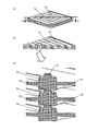
図14、図15(a)、図15(b)、図16(a)、図16(b)、図16(c)において、熱交換器1bは一辺が120mmの方形で厚みが2.0mmの単位素子2bを交互に90度回転しながら積層し、支持棒3にて単位素子2b同士を結束することにより構成され、伝熱板4の間に形成された通風路5に、一次気流Aと二次気流Bを流通すると、一次気流Aと二次気流Bとは伝熱板4を介して直交しながら熱交換を行う。   14, FIG. 15 (a), FIG. 15 (b), FIG. 16 (a), FIG. 16 (b), and FIG. 16 (c), the heat exchanger 1b is a square having a side of 120 mm and a thickness of 2.0 mm. The unit elements 2b are stacked while being alternately rotated by 90 degrees, and the unit elements 2b are bound together by the support rod 3, and the primary airflow A is formed in the ventilation path 5 formed between the heat transfer plates 4. When the secondary airflow B is circulated, the primary airflow A and the secondary airflow B exchange heat through the heat transfer plate 4 while being orthogonal to each other.

図15(a)および図15(b)の単位素子2bは、伝熱板4のX方向表面に間隔リブ6a、間隔リブ凸部29、遮蔽リブ7a、貫通穴9、貫通穴凸部10、位置決め凸部12、位置決め貫通穴13a、遮蔽リブ注入口14b、間隔リブ注入口15を備え、伝熱板4のY方向表面に間隔リブ6aa、間隔リブ凹部30、遮蔽リブ7aa、貫通穴9、位置決め貫通穴13aa、貫通穴凹部17、位置決め平面部19を備え、間隔リブ6a、6aaおよび遮蔽リブ7a、7aaが伝熱板4を間に挟むように、樹脂にて一体成形して得られる。   The unit element 2b of FIG. 15A and FIG. 15B has a spacing rib 6a, a spacing rib convex portion 29, a shielding rib 7a, a through hole 9, a through hole convex portion 10, on the X-direction surface of the heat transfer plate 4. Positioning convex part 12, positioning through hole 13a, shielding rib injection port 14b, interval rib injection port 15 are provided, interval rib 6aa, interval rib recess 30, shielding rib 7aa, through hole 9 on the Y-direction surface of heat transfer plate 4, The positioning through-hole 13aa, the through-hole concave portion 17, and the positioning flat surface portion 19 are provided, and the interval ribs 6a and 6aa and the shielding ribs 7a and 7aa are obtained by integral molding with resin so that the heat transfer plate 4 is sandwiched therebetween.

伝熱板4のX方向表面において、間隔リブ6aは高さ1mm、幅1mmで所定間隔に6本形成し、遮蔽リブ7aは伝熱板4の向かい合う一組の両端で間隔リブ6aと平行に高さ1mm、幅5mmに形成する。間隔リブ凸部29は間隔リブ6aの上面の両端に、凸高さ0.4mm、幅1mm、長さ15mmに凸形状に形成する。遮蔽リブ注入口14bは台形状で遮蔽リブ7aと連結し、通風路5の外側に、伝熱板4から凸高さ0.5mmに形成する。貫通穴9は単位素子2bの四隅であって、遮蔽リブ7aに4箇所穴を設ける。貫通穴凸部10は貫通穴9の4箇所の穴の一部として、方形の単位素子2bの対角する2箇所に、貫通穴9の穴の周囲に凸高さ0.4mmの凸形状を形成する。位置決め凸部12は間隔リブ6aの上面に凸高さ1.7mmで2個設け、位置決め貫通穴13aは間隔リブ6aに凸高さ1.0mmで2個の円筒を設け、間隔リブ注入口15は間隔リブ6aの上面に凹高さ0.5mmに間隔リブ6aの段を落とすような形状に形成する。   On the surface of the heat transfer plate 4 in the X direction, six spacing ribs 6a are formed at a predetermined interval with a height of 1 mm and a width of 1 mm, and the shielding ribs 7a are parallel to the spacing ribs 6a at a pair of opposite ends of the heat transfer plate 4. It is 1 mm high and 5 mm wide. The spacing rib projections 29 are formed in a convex shape at both ends of the top surface of the spacing rib 6a with a convex height of 0.4 mm, a width of 1 mm, and a length of 15 mm. The shield rib inlet 14b is trapezoidal and is connected to the shield rib 7a, and is formed outside the ventilation path 5 with a convex height of 0.5 mm from the heat transfer plate 4. The through holes 9 are the four corners of the unit element 2b, and four holes are provided in the shielding rib 7a. The through-hole convex part 10 has a convex shape with a convex height of 0.4 mm around the hole of the through-hole 9 as a part of the four holes of the through-hole 9 at two opposite corners of the rectangular unit element 2b. Form. Two positioning projections 12 are provided on the upper surface of the spacing rib 6a with a projection height of 1.7 mm, and the positioning through holes 13a are provided with two cylinders with a projection height of 1.0 mm on the spacing rib 6a. Is formed in such a shape that the step of the spacing rib 6a is dropped to a concave height of 0.5 mm on the upper surface of the spacing rib 6a.

伝熱板4のY方向表面において、間隔リブ6aaは間隔リブ6aと直交し、高さ1mm、幅1mmで所定間隔に6本形成し、遮蔽リブ7aaは伝熱板4の向かい合う一組の両端で間隔リブ6aaと平行に高さ1mm、幅5mmに形成する。間隔リブ凹部30は間隔リブ6aaの上面の両端に、凹高さ0.5mm、幅1mm、長さ15.1mmに凹形状に形成する。貫通穴9は単位素子2bの四隅であって、遮蔽リブ7aaに4箇所穴を設ける。貫通穴凹部17は貫通穴9の4箇所の穴の一部として、方形の単位素子2bの対角する2箇所に、貫通穴9の穴の周囲に凹高さ0.5mmの凹形状を形成する。位置決め平面部19は伝熱板4を挟んで位置決め凸部12の反対側に凸高さ1.0mmの円柱を2箇所設け、位置決め貫通穴13aaは伝熱板4を挟んで位置決め貫通穴13aの反対側に凸高さ1.0mmで2個の円筒を設ける。   On the surface in the Y direction of the heat transfer plate 4, the interval ribs 6 aa are orthogonal to the interval ribs 6 a, and are formed at a predetermined interval with a height of 1 mm and a width of 1 mm, and the shielding ribs 7 aa are a pair of opposite ends of the heat transfer plate 4. Thus, the height is 1 mm and the width is 5 mm in parallel with the spacing rib 6aa. The spacing rib recesses 30 are formed in a concave shape at both ends of the top surface of the spacing rib 6aa with a recess height of 0.5 mm, a width of 1 mm, and a length of 15.1 mm. The through holes 9 are the four corners of the unit element 2b, and four holes are provided in the shielding rib 7aa. The through-hole recess 17 is formed as a part of the four holes of the through-hole 9 and has a concave shape having a recess height of 0.5 mm around the hole of the through-hole 9 at two diagonal positions of the rectangular unit element 2b. To do. The positioning flat surface portion 19 is provided with two columns having a convex height of 1.0 mm on the opposite side of the positioning convex portion 12 with the heat transfer plate 4 interposed therebetween, and the positioning through hole 13aa is located between the positioning heat transfer plate 4 and the positioning through hole 13a. Two cylinders with a convex height of 1.0 mm are provided on the opposite side.

図16(a)、図16(b)、図16(c)に示すように、間隔リブ6aと間隔リブ6aaは単位素子2aを交互に90度回転しながら積層した時に、隣接する間隔リブ6aと間隔リブ6aaが重なり合うように形成され、伝熱板4を一定の間隔に保持する働がある。本実施の形態では、間隔リブ6aおよび間隔リブ6aaの凸高さを1mmとしたので、伝熱板4は2mm毎に積層される。   As shown in FIGS. 16 (a), 16 (b), and 16 (c), the spacing rib 6a and the spacing rib 6aa are adjacent to each other when the unit elements 2a are stacked while being alternately rotated by 90 degrees. And the spacing ribs 6aa are formed so as to overlap each other, and serves to hold the heat transfer plate 4 at a constant spacing. In the present embodiment, since the convex height of the spacing rib 6a and the spacing rib 6aa is 1 mm, the heat transfer plate 4 is laminated every 2 mm.

図16(a)、図16(b)、図16(c)に示すように、間隔リブ凸部29と間隔リブ凹部30は単位素子2bを交互に90度回転しながら正しく積層した時には、隣接する間隔リブ凸部29の凸部と間隔リブ凹部30の凹部が嵌合するよう形成される。熱交換器1bは間隔リブ6aおよび間隔リブ6aaに設けた間隔リブ凸部29と間隔リブ凹部30の嵌合により、単位素子2b同士が互いに固定化され、且つ単位素子2bを積層する際に発生する位置ずれを防止する。熱交換器1bの伝熱板4を一定の間隔に保持する構成は、図16(c)に示すように隣接する間隔リブ6aおよび間隔リブ6aa同士が重なり合うことにより行われ、間隔リブ凸部29の凸部と間隔リブ凹部30の凹部の嵌合も伝熱板4を一定の間隔に保持する。この明細書では、金型の製造精度と樹脂成形の精度を考慮して、間隔リブ6aおよび間隔リブ6aaは必ず重なり合うようにし、間隔リブ凸部29と間隔リブ凹部30の嵌合は、高さ方向に0.1mmの積層逃がし部20eを設けた。なお0.1mmの高さ方向の積層逃がし部20eを設けたが、単位素子2bを正しく積層した時に、熱交換器1bの伝熱板4が一定の間隔に保たれれば良く、熱交換器の設計や製造精度により適宜決定する。   As shown in FIGS. 16 (a), 16 (b), and 16 (c), the spacing rib protrusion 29 and the spacing rib recess 30 are adjacent to each other when the unit elements 2b are correctly stacked while rotating 90 degrees alternately. The convex part of the spacing rib convex part 29 and the concave part of the spacing rib concave part 30 are formed to be fitted. The heat exchanger 1b is generated when the unit elements 2b are laminated and the unit elements 2b are stacked by the fitting of the interval ribs 6a and the interval rib projections 29 provided on the interval ribs 6aa and the interval rib recesses 30. To prevent misalignment. The structure of holding the heat transfer plate 4 of the heat exchanger 1b at a constant interval is performed by overlapping the adjacent interval ribs 6a and the interval ribs 6aa as shown in FIG. The fitting of the convex portion and the concave portion of the spacing rib concave portion 30 also holds the heat transfer plate 4 at a constant interval. In this specification, in consideration of mold manufacturing accuracy and resin molding accuracy, the interval rib 6a and the interval rib 6aa are necessarily overlapped, and the interval rib protrusion 29 and the interval rib recess 30 are fitted to each other in height. A stacking relief portion 20e of 0.1 mm was provided in the direction. Although the stacking relief portion 20e in the height direction of 0.1 mm is provided, it is sufficient if the heat transfer plate 4 of the heat exchanger 1b is kept at a constant interval when the unit elements 2b are correctly stacked. It is determined appropriately according to the design and manufacturing accuracy.

図17(a)、図17(b)、図17(c)に示すように、単位素子2bを交互に90度回転せず、誤って積層した時には、間隔リブ凸部29の凸部は隣接する遮蔽リブ7aaと干渉し、隣接する単位素子2b同士が嵌合できず、熱交換器1bの側面から確認すると単位素子2b同士に隙間があり、容易に単位素子2bの積み間違いを確認することができる構成となっている。   As shown in FIG. 17A, FIG. 17B, and FIG. 17C, when the unit elements 2b are not rotated alternately by 90 degrees and are stacked incorrectly, the protrusions of the spacing rib protrusions 29 are adjacent to each other. The adjacent unit elements 2b cannot be fitted to each other due to interference with the shielding ribs 7aa, and when confirmed from the side surface of the heat exchanger 1b, there is a gap between the unit elements 2b, and the unit elements 2b can be easily confirmed to be stacked incorrectly. It has a configuration that can.

なお間隔リブ凸部29および間隔リブ凹部30は単位素子2bの間隔リブ6aおよび間隔リブ6aaに設けたが、単位素子を正しく積層した時には隣接する単位素子の凹部と凸部が嵌合し、誤って積層した時には凸部と隣接する単位素子の一部が干渉する構造であれば、その他の構成の熱交換器を用いても同様の作用効果を得ることができる。   The spacing rib protrusion 29 and the spacing rib recess 30 are provided in the spacing rib 6a and spacing rib 6aa of the unit element 2b. However, when the unit elements are correctly stacked, the recesses and the projections of the adjacent unit elements are fitted to each other. As long as a part of the unit element adjacent to the convex portion interferes when stacked, the same effect can be obtained even if a heat exchanger having another configuration is used.

図18(a)、図18(b)、図18(c)に示すように、貫通穴凹部17と貫通穴凸部10は単位素子2bを交互に90度回転しながら正しく積層した時には、隣接する貫通穴凹部17の凹部と貫通穴凸部10の凸部が嵌合するよう形成される。熱交換器1bは方形の単位素子2bの対角する2箇所に設けた貫通穴凹部17と貫通穴凸部10の嵌合により、単位素子2b同士が互いに固定化され、且つ単位素子2bを積層する際に発生する位置ずれを防止する。熱交換器1bの四隅における気流の遮蔽は、図18(c)に示すように隣接する遮蔽リブ7aおよび遮蔽リブ7aa同士が重なり合うことにより行われ、貫通穴凹部17の凹部と貫通穴凸部10の凸部の嵌合も気流の遮蔽を行う。   As shown in FIGS. 18 (a), 18 (b), and 18 (c), the through-hole concave portion 17 and the through-hole convex portion 10 are adjacent to each other when the unit elements 2b are correctly stacked while rotating 90 degrees alternately. The concave portion of the through-hole concave portion 17 and the convex portion of the through-hole convex portion 10 are formed to be fitted. In the heat exchanger 1b, the unit elements 2b are fixed to each other and the unit elements 2b are laminated by fitting the through-hole concave portions 17 and the through-hole convex portions 10 provided at two diagonal positions of the square unit element 2b. This prevents misalignment that occurs when Airflow shielding at the four corners of the heat exchanger 1b is performed by overlapping the adjacent shielding ribs 7a and shielding ribs 7aa as shown in FIG. 18 (c). The fitting of the protrusions also shields the airflow.

この明細書では、金型の製造精度と樹脂成形の精度を考慮して、遮蔽リブ7aおよび遮蔽リブ7aaは必ず重なり合うようにし、貫通穴凹部17と貫通穴凸部10の嵌合は、気流が漏れない程度に高さ方向に0.1mmの積層逃がし部20fを設けた。なお0.1mmの高さ方向の積層逃がし部20fを設けたが、単位素子2bを正しく積層した時には、熱交換器1bの四隅における気流の遮蔽と単位素子2b同士の嵌合ができれば良く、熱交換器の設計や製造精度により適宜決定する。   In this specification, in consideration of the manufacturing accuracy of the mold and the accuracy of resin molding, the shielding rib 7a and the shielding rib 7aa are necessarily overlapped. A stacking relief portion 20 f of 0.1 mm was provided in the height direction so as not to leak. Although the stacking relief part 20f in the height direction of 0.1 mm is provided, when the unit elements 2b are stacked correctly, it is only necessary to shield the air flow at the four corners of the heat exchanger 1b and fit the unit elements 2b to each other. It is determined appropriately according to the design and manufacturing accuracy of the exchanger.

図19(a)、図19(b)、図19(c)に示すように、単位素子2bを交互に90度回転せず、誤って積層した時には、貫通穴凸部10の凸部は隣接する遮蔽リブ7aaと干渉し、隣接する単位素子2b同士が嵌合できず、熱交換器1bの側面から確認すると単位素子2b同士に隙間があり、容易に単位素子2bの積み間違いを確認することができる構成となっている。   As shown in FIGS. 19 (a), 19 (b), and 19 (c), when the unit elements 2b are not rotated alternately by 90 degrees and are stacked incorrectly, the protrusions of the through-hole protrusions 10 are adjacent to each other. The adjacent unit elements 2b cannot be fitted to each other due to interference with the shielding ribs 7aa, and when confirmed from the side surface of the heat exchanger 1b, there is a gap between the unit elements 2b, and the unit elements 2b can be easily confirmed to be stacked incorrectly. It has a configuration that can.

なお貫通穴凹部17および貫通穴凸部10は貫通穴9の4箇所の穴の一部として、方形の単位素子2bの対角する2箇所に設けた。例えば、貫通穴9の4箇所に貫通穴凹部17の凹部と貫通穴凸部10の凸部を設けた場合、誤って単位素子2aを積層した時にも隣接する単位素子2aの貫通穴凹部17の凹部と貫通穴凸部10の凸部が嵌合し、単位素子2aの積み間違いが分からないため、貫通穴凹部17および貫通穴凸部10は貫通穴9の4箇所の穴の一部に備えた。この明細書では貫通穴9の4箇所の穴の一部として、方形の単位素子2bの対角する2箇所に設けが、貫通穴9の穴の一部とは、単位素子を正しく積層した時には隣接する単位素子の凹部と凸部が嵌合し、誤って積層した時には凸部と隣接する単位素子の一部が干渉する構造であれば、その他の構成の熱交換器を用いても同様の作用効果を得ることができる。   The through-hole concave portion 17 and the through-hole convex portion 10 were provided at two diagonal positions of the rectangular unit element 2b as part of the four holes of the through-hole 9. For example, when the concave portion of the through-hole concave portion 17 and the convex portion of the through-hole convex portion 10 are provided at four locations of the through-hole 9, even when the unit elements 2a are mistakenly stacked, the through-hole concave portions 17 of the adjacent unit elements 2a Since the concave portion and the convex portion of the through-hole convex portion 10 are fitted and the unit element 2a cannot be mistakenly stacked, the through-hole concave portion 17 and the through-hole convex portion 10 are provided in part of the four holes of the through-hole 9. It was. In this specification, as part of the four holes of the through-hole 9, the rectangular unit element 2 b is provided at two opposite corners. The part of the hole of the through-hole 9 means that the unit elements are correctly stacked. As long as the concave and convex portions of the adjacent unit elements are fitted together and a part of the unit elements adjacent to the convex portion interferes when they are mistakenly stacked, the same applies even if a heat exchanger of other configuration is used. An effect can be obtained.

熱交換器1bは単位素子2bを積層した時に隣接する単位素子2bが干渉しないように逃がす手段を備え、逃がす手段として、遮蔽リブ7aに連結し、通風路5の外側に遮蔽リブ注入口14bの段落としを設けた構成である。   The heat exchanger 1b is provided with a means for allowing the adjacent unit elements 2b not to interfere when the unit elements 2b are stacked. As a means for releasing, the heat exchanger 1b is connected to the shielding rib 7a, and the shielding rib inlet 14b is provided outside the ventilation path 5. It is the structure which provided the paragraph.

図14に示すように、遮蔽リブ注入口14bは通風路5の外側に段落としを設けたことにより、溶融樹脂が金型から注入される遮蔽リブ注入口14bにおいてバリが万一発生しても、単位素子2bを積層した際に隣接する単位素2b同士は段落しによってバリを逃がすことにより干渉せず、更に前記バリは通風路5の外側に位置するため、隣接する単位素子2bとの空間を大きくでき、バリを逃がすことにより更に干渉せず、隙間無く単位素子2bを積層することができる。   As shown in FIG. 14, the shielding rib injection port 14b is provided with a paragraph outside the ventilation path 5, so that even if a burr occurs in the shielding rib injection port 14b through which molten resin is injected from the mold. When the unit elements 2b are stacked, the adjacent unit elements 2b do not interfere with each other by escaping burrs by breaking, and the burrs are located outside the ventilation path 5, so that the space between the adjacent unit elements 2b The unit element 2b can be stacked without a gap without causing further interference by releasing the burr.

なお、遮蔽リブ注入口14bの段落しは遮蔽リブ7aに連結するように設けたが、溶融樹脂を注入する注入口は、遮蔽リブ7aの少なくとも何れかに連結し、通風路5の外側に設け、バリを逃がすように段落しにする構成であれば良く、その他の構成を用いても同様の作用効果を得ることができる。   Although the shielding rib inlet 14b is provided so as to be connected to the shielding rib 7a, the inlet for injecting molten resin is connected to at least one of the shielding ribs 7a and provided outside the ventilation path 5. Any other configuration may be used as long as the burrs are escaped, and similar effects can be obtained by using other configurations.

上記構成により、熱交換器1bは、単位素子2bを積層した際に積み間違いが分かる手段として、間隔リブ6a、6aaに間隔リブ凸部29と間隔リブ凹部30を備えたことにより、単位素子2bを正しく積層した時には隣接する単位素子2bの間隔リブ凸部29の凸部と間隔リブ凹部30の凹部が嵌合し、誤って積層した時には間隔リブ凸部29の凸部と隣接する単位素子2bの一部(遮蔽リブ7aa)が干渉するため、単位素子2bの積み間違いを容易に確認することができ、積み間違いを修正することによって生産工程の不良を低減することができ、量産性を向上することができる。また単位素子2bの積み間違いに起因する密封性の低下を防止することができ、気流の漏れを防止することができる。また間隔リブ凸部29の凸部と間隔リブ凹部30の凹部は単位素子2bを積層した際に凹部と凸部が嵌合することにより、単位素子2b同士が互いに固定するため、単位素子2bのずれに起因する密封性の低下を防止することができ、気流の漏れを防止することができ、また前記嵌合構造が単位素子2bを積層する際に発生する位置ずれを防止することにより、量産性を向上することができる。   With the above configuration, the heat exchanger 1b is provided with the spacing rib protrusions 29 and the spacing rib recesses 30 on the spacing ribs 6a and 6aa as means for understanding the stacking error when the unit elements 2b are stacked. Are correctly stacked, the projections of the spacing rib projections 29 of the adjacent unit elements 2b and the recesses of the spacing rib recesses 30 are fitted, and when the stacking is mistaken, the unit elements 2b adjacent to the projections of the spacing rib projections 29. Part (shielding rib 7aa) interferes, so it is possible to easily check the stacking error of the unit elements 2b. By correcting the stacking error, it is possible to reduce defects in the production process and improve mass productivity. can do. In addition, it is possible to prevent the sealing performance from being lowered due to erroneous stacking of the unit elements 2b, and to prevent airflow leakage. Further, since the convex portions of the spacing rib convex portion 29 and the concave portion of the spacing rib concave portion 30 are fixed to each other by fitting the concave portion and the convex portion when the unit elements 2b are stacked, the unit elements 2b are fixed to each other. Decrease in sealing performance due to deviation can be prevented, leakage of airflow can be prevented, and the fitting structure can prevent mass misalignment that occurs when the unit elements 2b are stacked. Can be improved.

また熱交換器1bは、単位素子2bに貫通穴9を備え、この貫通穴9の一部の周囲として、方形の単位素子2bの対角する2箇所に貫通穴凹部17および貫通穴凸部10を備えたことにより、単位素子2bを正しく積層した時には隣接する単位素子2bの貫通穴凹部17と貫通穴凸部10が嵌合し、誤って積層した時には貫通穴凸部10と隣接する単位素子2bの一部(遮蔽リブ7aa)が干渉するため、単位素子2bの積み間違いを容易に確認することができ、積み間違いを修正することによって生産工程の不良を低減することができ、量産性を向上することができる。また単位素子2bの積み間違いに起因する密封性の低下を防止することができ、気流の漏れを防止することができる。また単位素子2bを積層した際に貫通穴凹部17と貫通穴凸部10が嵌合することにより、単位素子2b同士が互いに固定するため、単位素子2bのずれに起因する密封性の低下を防止することができ、気流の漏れを防止することができ、また前記嵌合構造が単位素子2bを積層する際に発生する位置ずれを防止することにより、量産性を向上することができる。   The heat exchanger 1b includes a through-hole 9 in the unit element 2b, and a through-hole concave portion 17 and a through-hole convex portion 10 are provided at two opposite corners of the rectangular unit element 2b as a part of the through-hole 9. When the unit elements 2b are correctly stacked, the through-hole concave portions 17 and the through-hole convex portions 10 of the adjacent unit elements 2b are fitted, and when the unit elements 2b are erroneously stacked, the unit elements adjacent to the through-hole convex portions 10 are fitted. Since a part of 2b (shielding rib 7aa) interferes, it is possible to easily check the stacking error of the unit elements 2b, and by correcting the stacking error, it is possible to reduce defects in the production process, thereby increasing the mass productivity. Can be improved. In addition, it is possible to prevent the sealing performance from being lowered due to erroneous stacking of the unit elements 2b, and to prevent airflow leakage. In addition, when the unit elements 2b are stacked, the through-hole concave portion 17 and the through-hole convex portion 10 are fitted to each other so that the unit elements 2b are fixed to each other, thereby preventing deterioration in sealing performance due to deviation of the unit elements 2b. It is possible to prevent the leakage of airflow, and the mass productivity can be improved by preventing the misalignment that occurs when the fitting structure stacks the unit elements 2b.

また遮蔽リブ注入口14bの段落としは、遮蔽リブ7aに連結し、通風路5の外側に設けたことにより、溶融樹脂が射出成形金型24から注入される単位素子2bの注入口においてバリが万一発生しても、単位素子2bを積層した際に隣接する単位素子2b同士は段落しによってバリを逃がすことにより干渉せず、更に前記バリは通風路5の外側に位置するため、隣接する単位素子2bとの空間を大きくでき、バリを逃がすことにより更に干渉せず、隙間無く単位素子2bを積層することができ、気流の漏れを防止することができる。   Further, as the paragraph of the shielding rib injection port 14b, it is connected to the shielding rib 7a and provided outside the ventilation path 5, so that burrs are generated at the injection port of the unit element 2b into which the molten resin is injected from the injection mold 24. Even if the unit elements 2b are stacked, the adjacent unit elements 2b do not interfere with each other by burring out the adjacent unit elements 2b, and further, the burrs are located outside the ventilation path 5, so that they are adjacent to each other. The space between the unit elements 2b can be increased, and the unit elements 2b can be stacked without any gap without causing further interference by escaping burrs, thereby preventing airflow leakage.

(実施の形態3)
図20(a)はX方向から見た単位素子の概略斜視図、図20(b)はY方向から見た単位素子の概略斜視図、図20(c)は遮蔽リブ注入口14aの概略拡大斜視図である。
(Embodiment 3)
20A is a schematic perspective view of the unit element viewed from the X direction, FIG. 20B is a schematic perspective view of the unit element viewed from the Y direction, and FIG. 20C is a schematic enlarged view of the shielding rib injection port 14a. It is a perspective view.

実施の形態1、2と同一部分は同一符号を附し詳細な説明は省略する。同一の作用効果を有する。   The same parts as those in the first and second embodiments are denoted by the same reference numerals, and detailed description thereof is omitted. Has the same effect.

図20(a)、図20(b)、図20(c)は図2(a)、図2(b)と同じ形状であり、遮蔽リブ注入口14aの位置を説明するために、単位素子2aの伝熱板4を除いた図である。図20(a)、図20(b)、図20(c)の単位素子2aの遮蔽リブ注入口14aおよび間隔リブ注入口15は、単位素子2aを積層した時に隣接する単位素子2aが干渉しないように逃がす手段を備え、逃がす手段として、間隔リブ6aおよび遮蔽リブ7aに段落としを設け、段落としとして遮蔽リブ7aに連結し、通風路5内に遮蔽リブ注入口14aを設ける。遮蔽リブ注入口14aは遮蔽リブ7aと間隔リブ6aaが交差する位置に2箇所設けた構成である。また間隔リブ6aと間隔リブ6aaは何れかで連結するように構成し、6本の間隔リブ6aと6本の間隔リブ6aaは直交するように交差して連結する構成とする。   20 (a), 20 (b), and 20 (c) have the same shape as FIGS. 2 (a) and 2 (b), and in order to explain the position of the shielding rib injection port 14a, the unit element It is the figure except the heat-transfer plate 4 of 2a. 20A, 20B, and 20C, the shielding rib injection port 14a and the spacing rib injection port 15 of the unit element 2a do not interfere with each other when adjacent unit elements 2a are stacked. As a means for escaping, the spacing rib 6a and the shielding rib 7a are provided with paragraphs, connected as a paragraph to the shielding ribs 7a, and the shielding rib inlet 14a is provided in the ventilation path 5. The shielding rib inlet 14a is provided at two positions where the shielding rib 7a and the spacing rib 6aa intersect. The spacing ribs 6a and the spacing ribs 6aa are configured to be connected to each other, and the six spacing ribs 6a and the six spacing ribs 6aa are configured to cross and be connected so as to be orthogonal to each other.

成形工程23において、溶融した樹脂は単位素子2aのX方向からから射出成形金型24内に射出すると、樹脂流路を通り、金型のゲート部から単位素子2aに設けた遮蔽リブ注入口14aおよび間隔リブ注入口15から流入し、間隔リブ6aおよび遮蔽リブ7aを成形すると共に、間隔リブ6aaおよび遮蔽リブ7aaと連結する形で形成する。遮蔽リブ注入口14aは遮蔽リブ7aと間隔リブ6aaが交差する位置に設けたことにより、射出成形金型24内において遮蔽リブ注入口14aから注入された溶融樹脂は、単位素子2aを樹脂で形成する遮蔽リブ7a、7aaと間隔リブ6a、6aaに同時に流れるため樹脂成形性が良好である。また、間隔リブ6aと間隔リブ6aaは何れかで連結しているため、間隔リブ6a、6aaに流れ込んできた溶融樹脂は間隔リブ6aと間隔リブ6aaが連結している部分から分岐して流れるため樹脂成形性は更に良好になり、樹脂成形する射出圧力を低くすることができ、樹脂成形機の能力を小さくすることができるため、設備投資を小さくすることができるので、製造コストを低減することができる。   In the molding step 23, when the molten resin is injected into the injection mold 24 from the X direction of the unit element 2a, it passes through the resin flow path, and the shielding rib injection port 14a provided in the unit element 2a from the gate portion of the mold. In addition, the gap rib 6a and the shielding rib 7a flow from the gap rib inlet 15 and are formed so as to be connected to the gap rib 6aa and the shield rib 7aa. By providing the shielding rib injection port 14a at a position where the shielding rib 7a and the spacing rib 6aa intersect, the molten resin injected from the shielding rib injection port 14a in the injection mold 24 forms the unit element 2a with resin. The resin moldability is good because the shielding ribs 7a and 7aa and the spacing ribs 6a and 6aa flow simultaneously. Further, since the spacing rib 6a and the spacing rib 6aa are connected to each other, the molten resin that has flowed into the spacing ribs 6a and 6aa flows from the portion where the spacing rib 6a and the spacing rib 6aa are connected to flow. The resin moldability is further improved, the injection pressure for resin molding can be lowered, the capacity of the resin molding machine can be reduced, and the capital investment can be reduced, thus reducing the manufacturing cost. Can do.

なお実施の形態3では遮蔽リブ注入口14aおよび間隔リブ注入口15を設けて説明したが、間隔リブ注入口15を除き、遮蔽リブ注入口14aだけの構成としても、遮蔽リブ注入口14aは遮蔽リブ7aと間隔リブ6aaが交差する位置に設けたことにより、成形工程23の射出成形金型24内において遮蔽リブ注入口14aから注入された溶融樹脂は、単位素子2aを樹脂で形成する遮蔽リブ7a、7aaと間隔リブ6a、6aaに同時に流れるため樹脂成形性を良好にすることができる。   In the third embodiment, the shielding rib injection port 14a and the spacing rib injection port 15 are provided. However, the shielding rib injection port 14a is shielded even if only the shielding rib injection port 14a is configured except the spacing rib injection port 15. By providing the rib 7a and the spacing rib 6aa at the intersecting position, the molten resin injected from the shielding rib injection port 14a in the injection mold 24 in the molding step 23 is a shielding rib for forming the unit element 2a with resin. Since it flows to 7a, 7aa and the space | interval rib 6a, 6aa simultaneously, resin moldability can be made favorable.

上記構成により、熱交換器1aは、段落としとして設けた遮蔽リブ注入口14aを遮蔽リブ7aと間隔リブ6aaが交差する位置に設けたことにより、射出成形金型24内において遮蔽リブ注入口14aから注入された溶融樹脂は、単位素子2aを樹脂で形成する遮蔽リブ7a、7aaと間隔リブ6a、6aaに同時に流れるため樹脂成形性が良好である。また遮蔽リブ7aと間隔リブ6aaが交差する位置は単位素子2aにおいて樹脂の肉厚(容積)が大きいため、この位置に遮蔽リブ注入口14aを設けたことにより、樹脂成形する射出圧力を低くすることができ、樹脂成形機の能力を小さくすることができるため、設備投資を小さくすることができるので、製造コストを低減することができる。   With the above configuration, the heat exchanger 1a is provided with the shielding rib injection port 14a provided as a paragraph at a position where the shielding rib 7a and the spacing rib 6aa intersect, so that the shielding rib injection port 14a in the injection mold 24 is provided. Since the molten resin injected from the flows simultaneously through the shielding ribs 7a and 7aa and the spacing ribs 6a and 6aa that form the unit element 2a with resin, the resin moldability is good. Further, since the thickness (volume) of the resin in the unit element 2a is large at the position where the shielding rib 7a and the spacing rib 6aa intersect, the shielding rib injection port 14a is provided at this position to lower the injection pressure for resin molding. Since the capacity of the resin molding machine can be reduced, the capital investment can be reduced, and the manufacturing cost can be reduced.

また、熱交換器1aは、間隔リブ6aと間隔リブ6aaは何れかで連結していることにより、射出成形金型24内において遮蔽リブ注入口14aから注入された溶融樹脂は、単位素子2aを樹脂で形成する遮蔽リブ7a、7aaと間隔リブ6a、6aaに同時に流れることに加え、間隔リブ6aと間隔リブ6aaは何れかで連結しているため、間隔リブ6a、6aaに流れ込んできた溶融樹脂は間隔リブ6aと間隔リブ6aaが連結している部分から分岐して流れるため樹脂成形性が良好であり、樹脂成形する射出圧力を低くすることができ、樹脂成形機の能力を小さくすることができるため、設備投資を小さくすることができるので、製造コストを低減することができる。   Further, in the heat exchanger 1a, the interval rib 6a and the interval rib 6aa are connected to each other, so that the molten resin injected from the shielding rib injection port 14a in the injection mold 24 has the unit element 2a. In addition to flowing simultaneously to the shielding ribs 7a, 7aa and the spacing ribs 6a, 6aa formed of resin, since the spacing rib 6a and the spacing rib 6aa are connected by any one, the molten resin that has flowed into the spacing ribs 6a, 6aa Has a good resin moldability because it flows from the portion where the gap ribs 6a and the gap ribs 6aa are connected, so that the injection pressure for resin molding can be lowered, and the capacity of the resin molding machine can be reduced. Therefore, the capital investment can be reduced, and the manufacturing cost can be reduced.

また、遮蔽リブ注入口14aを遮蔽リブ7aと間隔リブ6aaが交差する位置に設けたことや間隔リブ6aと間隔リブ6aaは何れかで連結していることにより、樹脂成形する射出圧力を低くすることができるため、遮蔽リブ注入口14aや間隔リブ注入口15などのゲート部を減少することができ、射出成形金型24にランナーレスにする手段として、オープンゲート式またはバルブゲート式のホットランナーを使用する場合、ホットランナーの数を減少することができため、設備投資を小さくすることができるので、製造コストを低減することができる。また樹脂成形する射出圧力を低くすることができるため、遮蔽リブ注入口14aや間隔リブ注入口15などのゲート部を減少することができため、樹脂成形した際の合流部(ウエルド)が減少するため、樹脂成形品の強度を高めることができる。   Further, the injection pressure for resin molding is lowered by providing the shielding rib inlet 14a at a position where the shielding rib 7a and the spacing rib 6aa intersect or by connecting the spacing rib 6a and the spacing rib 6aa. Therefore, the gate portions such as the shielding rib injection port 14a and the interval rib injection port 15 can be reduced, and an open gate type or valve gate type hot runner can be used as a means for making the injection mold 24 runnerless. Since the number of hot runners can be reduced and the capital investment can be reduced, the manufacturing cost can be reduced. In addition, since the injection pressure for resin molding can be lowered, the gate portions such as the shielding rib injection port 14a and the interval rib injection port 15 can be reduced, so that the merging portion (weld) at the time of resin molding is reduced. Therefore, the strength of the resin molded product can be increased.

本発明は、家庭用の熱交換型換気扇やビルなどの全熱交換型換気装置などに使用する積層構造の熱交換器などの用途に関するものである。   The present invention relates to a use of a heat exchanger having a laminated structure used for a heat exchange type ventilation fan for home use or a total heat exchange type ventilation device such as a building.

本発明の実施の形態1による熱交換器の概略斜視図1 is a schematic perspective view of a heat exchanger according to Embodiment 1 of the present invention. (a)同X方向から見た単位素子の概略斜視図、(b)同Y方向から見た単位素子の概略斜視図(A) The schematic perspective view of the unit element seen from the X direction, (b) The schematic perspective view of the unit element seen from the Y direction 同熱交換器の概略分解斜視図Schematic exploded perspective view of the heat exchanger (a)同単位素子を正しく積層した熱交換器の概略斜視図、(b)同A−A断面の熱交換器の概略斜視図、(c)同A−A断面の熱交換器の概略拡大斜視図(A) The schematic perspective view of the heat exchanger which laminated | stacked the same unit element correctly, (b) The schematic perspective view of the heat exchanger of the AA cross section, (c) The schematic expansion of the heat exchanger of the AA cross section Perspective view (a)同単位素子を誤って積層した熱交換器の概略斜視図、(b)同熱交換器の概略拡大斜視図(A) The schematic perspective view of the heat exchanger which laminated | stacked the same unit element accidentally, (b) The schematic enlarged perspective view of the heat exchanger (a)同単位素子を正しく積層した熱交換器の概略斜視図、(b)同B−B断面の熱交換器の概略斜視図、(c)同B−B断面の熱交換器の概略拡大斜視図(A) Schematic perspective view of a heat exchanger in which the same unit elements are correctly stacked, (b) Schematic perspective view of a heat exchanger in the BB cross section, (c) Schematic enlargement of the heat exchanger in the BB cross section Perspective view (a)同単位素子を誤って積層した熱交換器の概略斜視図、(b)同C−C断面の熱交換器の概略斜視図、(c)同C−C断面の熱交換器の概略拡大斜視図(A) The schematic perspective view of the heat exchanger which laminated | stacked the same unit element accidentally, (b) The schematic perspective view of the heat exchanger of the CC section, (c) The outline of the heat exchanger of the CC section Enlarged perspective view 同伝熱板の概略斜視図Schematic perspective view of the heat transfer plate (a)同単位素子を正しく積層した熱交換器の概略斜視図、(b)同B−B断面の熱交換器の概略斜視図、(c)同B−B断面の熱交換器の概略拡大斜視図(A) Schematic perspective view of a heat exchanger in which the same unit elements are correctly stacked, (b) Schematic perspective view of a heat exchanger in the BB cross section, (c) Schematic enlargement of the heat exchanger in the BB cross section Perspective view (a)同単位素子を誤って積層した熱交換器の概略斜視図、(b)同C−C断面の熱交換器の概略斜視図、(c)同C−C断面の熱交換器の概略拡大斜視図(A) The schematic perspective view of the heat exchanger which laminated | stacked the same unit element accidentally, (b) The schematic perspective view of the heat exchanger of the CC section, (c) The outline of the heat exchanger of the CC section Enlarged perspective view 同熱交換器の概略量産工程図Schematic mass production process diagram of the heat exchanger 同射出成形金型の概略断面図Schematic cross section of the same injection mold (a)同単位素子を正しく積層した熱交換器の概略斜視図、(b)同B−B断面の熱交換器の概略斜視図、(c)同B−B断面の熱交換器の概略拡大斜視図(A) Schematic perspective view of a heat exchanger in which the same unit elements are correctly stacked, (b) Schematic perspective view of a heat exchanger in the BB cross section, (c) Schematic enlargement of the heat exchanger in the BB cross section Perspective view 本発明の実施の形態2による熱交換器の概略斜視図Schematic perspective view of a heat exchanger according to Embodiment 2 of the present invention (a)同X方向から見た単位素子の概略斜視図、(b)同Y方向から見た単位素子の概略斜視図(A) The schematic perspective view of the unit element seen from the X direction, (b) The schematic perspective view of the unit element seen from the Y direction (a)同単位素子を正しく積層した熱交換器の概略斜視図、(b)同D−D断面の熱交換器の概略斜視図、(c)同D−D断面の熱交換器の概略拡大斜視図(A) Schematic perspective view of a heat exchanger in which the same unit elements are correctly stacked, (b) Schematic perspective view of a heat exchanger with the DD cross section, (c) Schematic enlargement of the heat exchanger with the DD cross section Perspective view (a)同単位素子を誤って積層した熱交換器の概略斜視図、(b)同E−E断面の熱交換器の概略斜視図、(c)同E−E断面の熱交換器の概略拡大斜視図(A) The schematic perspective view of the heat exchanger which laminated | stacked the same unit element accidentally, (b) The schematic perspective view of the heat exchanger of the EE cross section, (c) The outline of the heat exchanger of the EE cross section Enlarged perspective view (a)同単位素子を正しく積層した熱交換器の概略斜視図、(b)同F−F断面の熱交換器の概略斜視図、(c)同F−F断面の熱交換器の概略拡大斜視図(A) Schematic perspective view of a heat exchanger in which the same unit elements are correctly stacked, (b) Schematic perspective view of a heat exchanger with the same FF cross section, (c) Schematic enlargement of the heat exchanger with the same FF cross section Perspective view (a)同単位素子を誤って積層した熱交換器の概略斜視図、(b)同G−G断面の熱交換器の概略斜視図、(c)同G−G断面の熱交換器の概略拡大斜視図(A) The schematic perspective view of the heat exchanger which laminated | stacked the same unit element accidentally, (b) The schematic perspective view of the heat exchanger of the GG cross section, (c) The outline of the heat exchanger of the GG cross section. Enlarged perspective view (a)本発明の実施の形態3によるX方向から見た単位素子の概略斜視図、(b)同Y方向から見た単位素子の概略斜視図、(c)同遮蔽リブ注入口14aの概略拡大斜視図(A) Schematic perspective view of a unit element viewed from the X direction according to Embodiment 3 of the present invention, (b) Schematic perspective view of the unit element viewed from the Y direction, (c) Schematic of the shielding rib injection port 14a Enlarged perspective view (a)従来の熱交換器109のスペーサー101をX方向から見た概略斜視図、(b)従来の熱交換器109のスペーサー101をY方向から見た概略斜視図(A) The schematic perspective view which looked at the spacer 101 of the conventional heat exchanger 109 from the X direction, (b) The schematic perspective view which looked at the spacer 101 of the conventional heat exchanger 109 from the Y direction 従来の熱交換器109を示す概略斜視図Schematic perspective view showing a conventional heat exchanger 109

符号の説明Explanation of symbols

1a 熱交換器
1b 熱交換器
2a 単位素子
2b 単位素子
3 支持棒
4 伝熱板
5 通風路
6a 間隔リブ
6aa 間隔リブ
7a 遮蔽リブ
7aa 遮蔽リブ
8 遮蔽リブ凹部
9 貫通穴
10 貫通穴凸部
11 積層確認凸部
12 位置決め凸部
13a 位置決め貫通穴
13aa 位置決め貫通穴
14a 遮蔽リブ注入口
14b 遮蔽リブ注入口
15 間隔リブ注入口
16 遮蔽リブ凸部
17 貫通穴凹部
18 積層確認凹部
19 位置決め平面部
20a 積層逃がし部
20b 積層逃がし部
20c 積層逃がし部
20d 積層逃がし部
20e 積層逃がし部
20f 積層逃がし部
21 位置決め穴
22 切断工程
23 成形工程
24 射出成形金型
25 ヒータ
26 スプル・ランナー
27 積層工程
28 結束工程
29 間隔リブ凸部
30 間隔リブ凹部
DESCRIPTION OF SYMBOLS 1a Heat exchanger 1b Heat exchanger 2a Unit element 2b Unit element 3 Support rod 4 Heat transfer plate 5 Ventilation path 6a Spacing rib 6aa Spacing rib 7a Shielding rib 7aa Shading rib 8 Shielding rib concave part 9 Through hole 10 Through hole convex part 11 Lamination Confirmation convex part 12 Positioning convex part 13a Positioning through hole 13aa Positioning through hole 14a Shielding rib inlet 14b Shielding rib inlet 15 Interval rib inlet 16 Shielding rib convex part 17 Through hole concave part 18 Stacking confirmation concave part 19 Positioning flat part 20a Lamination relief Part 20b Lamination relief part 20c Lamination relief part 20d Lamination relief part 20e Lamination relief part 20f Lamination relief part 21 Positioning hole 22 Cutting process 23 Molding process 24 Injection mold 25 Heater 26 Sprue runner 27 Lamination process 28 Binding process 29 Spacing rib 29 Convex part 30 Spacing rib concave part

Claims (7)

伝熱板と前記伝熱板の間隔を保持するための間隔リブと気流の漏れを遮蔽するための遮蔽リブとを樹脂にて一体成形して単位素子を形成し、この単位素子を複数積層することにより前記伝熱板間に通風路が形成され、一次気流と二次気流を前記通風路に流通することにより、前記伝熱板を介して熱交換するようにした熱交換器において、前記間隔リブまたは前記遮蔽リブの少なくとも何れか、または前記間隔リブまたは前記遮蔽リブの少なくとも何れかに連結する位置に溶融樹脂を注入する注入口を設け、前記間隔リブおよび前記遮蔽リブが何れかで連結していることを特徴とする熱交換器。 A unit element is formed by integrally molding a spacing rib for maintaining a gap between the heat transfer plate and the heat transfer plate and a shielding rib for shielding airflow leakage to form a unit element, and a plurality of the unit elements are stacked. In the heat exchanger in which a ventilation path is formed between the heat transfer plates, and heat exchange is performed via the heat transfer plates by circulating a primary airflow and a secondary airflow through the ventilation path, the interval An injection port for injecting molten resin is provided at a position connected to at least one of the ribs and the shielding ribs, or at least one of the spacing ribs and the shielding ribs, and the spacing ribs and the shielding ribs are connected to each other. A heat exchanger characterized by that. 注入口は、単位素子を積層した時に隣接する前記単位素子が干渉しないように逃がす手段を備えたことを特徴とする請求項1記載の熱交換器。 2. The heat exchanger according to claim 1, wherein the injection port includes means for allowing the adjacent unit elements to escape when the unit elements are stacked. 逃がす手段として、間隔リブまたは遮蔽リブの少なくとも何れかに段落としを設けたことを特徴とする請求項2記載の熱交換器。 The heat exchanger according to claim 2, wherein at least one of the interval rib and the shielding rib is provided with a paragraph as the escape means. 段落としは、間隔リブまたは遮蔽リブの少なくとも何れかに連結し、通風路内に設けたことを特徴とする請求項3記載の熱交換器。 4. The heat exchanger according to claim 3, wherein the paragraph is connected to at least one of the interval rib and the shielding rib and provided in the ventilation path. 段落としは、遮蔽リブに連結し、通風路外に設けたことを特徴とする請求項3記載の熱交換器。 The heat exchanger according to claim 3, wherein the paragraph is connected to the shielding rib and provided outside the ventilation path. 段落としは、遮蔽リブと間隔リブが交差する位置に設けたことを特徴とする請求項4記載の熱交換器。 The heat exchanger according to claim 4, wherein the paragraph is provided at a position where the shielding rib and the spacing rib intersect. 複数の間隔リブは何れかの間隔リブで連結していることを特徴とする請求項6記載の熱交換器。 The heat exchanger according to claim 6, wherein the plurality of spacing ribs are connected by any spacing rib.
JP2007064768A 2006-03-22 2007-03-14 Heat exchanger Pending JP2007285691A (en)

Priority Applications (1)

Application Number Priority Date Filing Date Title
JP2007064768A JP2007285691A (en) 2006-03-22 2007-03-14 Heat exchanger

Applications Claiming Priority (2)

Application Number Priority Date Filing Date Title
JP2006078432 2006-03-22
JP2007064768A JP2007285691A (en) 2006-03-22 2007-03-14 Heat exchanger

Publications (2)

Publication Number Publication Date
JP2007285691A true JP2007285691A (en) 2007-11-01
JP2007285691A5 JP2007285691A5 (en) 2010-04-22

Family

ID=38757629

Family Applications (1)

Application Number Title Priority Date Filing Date
JP2007064768A Pending JP2007285691A (en) 2006-03-22 2007-03-14 Heat exchanger

Country Status (1)

Country Link
JP (1) JP2007285691A (en)

Cited By (16)

* Cited by examiner, † Cited by third party
Publication number Priority date Publication date Assignee Title
WO2009078168A1 (en) * 2007-12-17 2009-06-25 Panasonic Corporation Heat exchange device and device for receiving heat generation body
JP2009168435A (en) * 2007-12-17 2009-07-30 Panasonic Corp Heat exchanging device and heating element storage device using the same
WO2012090748A1 (en) * 2010-12-28 2012-07-05 三菱重工業株式会社 Method for manufacturing hot-water heater, and hot-water heater manufactured thereby
JP2012167847A (en) * 2011-02-14 2012-09-06 Mitsubishi Electric Corp Plate heat exchanger and heat pump device
WO2013157055A1 (en) * 2012-04-18 2013-10-24 三菱電機株式会社 Heat-exchange element and air conditioner
WO2013157045A1 (en) * 2012-04-20 2013-10-24 三菱電機株式会社 Heat exchange element
JP5797328B2 (en) * 2012-04-20 2015-10-21 三菱電機株式会社 Heat exchange element
WO2017169410A1 (en) * 2016-03-28 2017-10-05 パナソニックIpマネジメント株式会社 Heat exchanger
AU2014231681B2 (en) * 2013-03-14 2018-06-28 Nortek Air Solutions Canada, Inc. Membrane-integrated energy exchange assembly
WO2020203556A1 (en) * 2019-04-05 2020-10-08 ダイキン工業株式会社 Heat exchanger
JP2020169780A (en) * 2019-04-05 2020-10-15 ダイキン工業株式会社 Heat exchanger
JP2020169781A (en) * 2019-04-05 2020-10-15 ダイキン工業株式会社 Heat exchanger
JP2021042902A (en) * 2019-09-11 2021-03-18 ダイキン工業株式会社 Heat exchanger
CN113864891A (en) * 2021-08-31 2021-12-31 华为数字能源技术有限公司 Heat exchange chip, heat exchange core and air conditioning box
WO2023286110A1 (en) * 2021-07-12 2023-01-19 三菱電機株式会社 Heat exchange element
WO2023243313A1 (en) * 2022-06-15 2023-12-21 パナソニックIpマネジメント株式会社 Stacked structure, and heat-exchange-type ventilation device and air purification device using same

Citations (11)

* Cited by examiner, † Cited by third party
Publication number Priority date Publication date Assignee Title
JPS63205833A (en) * 1987-02-20 1988-08-25 Matsushita Electric Ind Co Ltd Production of optical disk substrate
JPH05322048A (en) * 1992-05-22 1993-12-07 Kubota Corp Seal ring and its manufacture
JPH08110076A (en) * 1994-10-11 1996-04-30 Matsushita Seiko Co Ltd Heat exchanging element
JP2000024843A (en) * 1998-07-09 2000-01-25 Matsushita Seiko Co Ltd Manufacture of heat exchanger
JP2001167956A (en) * 1999-12-08 2001-06-22 Toyota Autom Loom Works Ltd Device for supporting paddle for feeding
JP2002326257A (en) * 2001-05-07 2002-11-12 Mitsubishi Electric Corp Injection molding machine for seal member
JP2003025379A (en) * 2001-07-11 2003-01-29 Nakanishi Metal Works Co Ltd Method for manufacturing precise resin product, and seal for bearing
JP2003287387A (en) * 2002-03-28 2003-10-10 Matsushita Ecology Systems Co Ltd Heat exchange membrane and heat exchange element
JP2004144148A (en) * 2002-10-22 2004-05-20 Nsk Ltd Plastic seal for bearing
JP2005282907A (en) * 2004-03-29 2005-10-13 Matsushita Electric Ind Co Ltd Heat exchanger
JP2006029692A (en) * 2004-07-16 2006-02-02 Matsushita Electric Ind Co Ltd Heat exchanger

Patent Citations (11)

* Cited by examiner, † Cited by third party
Publication number Priority date Publication date Assignee Title
JPS63205833A (en) * 1987-02-20 1988-08-25 Matsushita Electric Ind Co Ltd Production of optical disk substrate
JPH05322048A (en) * 1992-05-22 1993-12-07 Kubota Corp Seal ring and its manufacture
JPH08110076A (en) * 1994-10-11 1996-04-30 Matsushita Seiko Co Ltd Heat exchanging element
JP2000024843A (en) * 1998-07-09 2000-01-25 Matsushita Seiko Co Ltd Manufacture of heat exchanger
JP2001167956A (en) * 1999-12-08 2001-06-22 Toyota Autom Loom Works Ltd Device for supporting paddle for feeding
JP2002326257A (en) * 2001-05-07 2002-11-12 Mitsubishi Electric Corp Injection molding machine for seal member
JP2003025379A (en) * 2001-07-11 2003-01-29 Nakanishi Metal Works Co Ltd Method for manufacturing precise resin product, and seal for bearing
JP2003287387A (en) * 2002-03-28 2003-10-10 Matsushita Ecology Systems Co Ltd Heat exchange membrane and heat exchange element
JP2004144148A (en) * 2002-10-22 2004-05-20 Nsk Ltd Plastic seal for bearing
JP2005282907A (en) * 2004-03-29 2005-10-13 Matsushita Electric Ind Co Ltd Heat exchanger
JP2006029692A (en) * 2004-07-16 2006-02-02 Matsushita Electric Ind Co Ltd Heat exchanger

Cited By (28)

* Cited by examiner, † Cited by third party
Publication number Priority date Publication date Assignee Title
JP2009168435A (en) * 2007-12-17 2009-07-30 Panasonic Corp Heat exchanging device and heating element storage device using the same
EP2233875A1 (en) * 2007-12-17 2010-09-29 Panasonic Corporation Heat exchange device and device for receiving heat generation body
CN101903737B (en) * 2007-12-17 2012-05-23 松下电器产业株式会社 Heat exchange device and device for receiving heat generation body by using the heat exchange device
WO2009078168A1 (en) * 2007-12-17 2009-06-25 Panasonic Corporation Heat exchange device and device for receiving heat generation body
EP2233875A4 (en) * 2007-12-17 2014-04-02 Panasonic Corp Heat exchange device and device for receiving heat generation body
WO2012090748A1 (en) * 2010-12-28 2012-07-05 三菱重工業株式会社 Method for manufacturing hot-water heater, and hot-water heater manufactured thereby
JP2012167847A (en) * 2011-02-14 2012-09-06 Mitsubishi Electric Corp Plate heat exchanger and heat pump device
EP2851642A4 (en) * 2012-04-18 2016-03-02 Mitsubishi Electric Corp Heat-exchange element and air conditioner
WO2013157055A1 (en) * 2012-04-18 2013-10-24 三菱電機株式会社 Heat-exchange element and air conditioner
US9903669B2 (en) 2012-04-18 2018-02-27 Mitsubishi Electric Corporation Heat exchange element and air conditioner
WO2013157040A1 (en) * 2012-04-18 2013-10-24 三菱電機株式会社 Heat-exchange element and air conditioner
US9664452B2 (en) 2012-04-20 2017-05-30 Mitsubishi Electric Corporation Heat exchange element
JPWO2013157056A1 (en) * 2012-04-20 2015-12-21 三菱電機株式会社 Heat exchange element
JP5797328B2 (en) * 2012-04-20 2015-10-21 三菱電機株式会社 Heat exchange element
WO2013157056A1 (en) * 2012-04-20 2013-10-24 三菱電機株式会社 Heat exchange element
WO2013157045A1 (en) * 2012-04-20 2013-10-24 三菱電機株式会社 Heat exchange element
US10352629B2 (en) 2012-04-20 2019-07-16 Mitsubishi Electric Corporation Heat exchange element
AU2014231681B2 (en) * 2013-03-14 2018-06-28 Nortek Air Solutions Canada, Inc. Membrane-integrated energy exchange assembly
WO2017169410A1 (en) * 2016-03-28 2017-10-05 パナソニックIpマネジメント株式会社 Heat exchanger
JP2017180856A (en) * 2016-03-28 2017-10-05 パナソニックIpマネジメント株式会社 Heat exchanger
WO2020203556A1 (en) * 2019-04-05 2020-10-08 ダイキン工業株式会社 Heat exchanger
JP2020169780A (en) * 2019-04-05 2020-10-15 ダイキン工業株式会社 Heat exchanger
JP2020169781A (en) * 2019-04-05 2020-10-15 ダイキン工業株式会社 Heat exchanger
JP2021042902A (en) * 2019-09-11 2021-03-18 ダイキン工業株式会社 Heat exchanger
WO2023286110A1 (en) * 2021-07-12 2023-01-19 三菱電機株式会社 Heat exchange element
CN113864891A (en) * 2021-08-31 2021-12-31 华为数字能源技术有限公司 Heat exchange chip, heat exchange core and air conditioning box
CN113864891B (en) * 2021-08-31 2023-03-03 华为数字能源技术有限公司 Heat exchange chip, heat exchange core and air conditioning box
WO2023243313A1 (en) * 2022-06-15 2023-12-21 パナソニックIpマネジメント株式会社 Stacked structure, and heat-exchange-type ventilation device and air purification device using same

Similar Documents

Publication Publication Date Title
JP4770534B2 (en) Heat exchanger
JP2007285691A (en) Heat exchanger
US8002023B2 (en) Heat exchanger and its manufacturing method
JP4816517B2 (en) Heat exchange element
JP2008070046A (en) Heat exchange element
JP2018018582A (en) Fuel battery single cell and manufacturing method thereof
KR101114786B1 (en) Heat exchange element
JP4765706B2 (en) Manufacturing method of heat exchanger
KR101574036B1 (en) Total heat exchange element and method for manufacturing same
JP2007213971A (en) Cell for polymer electrolyte fuel cell and polymer electrolyte fuel cell using it
WO2015037688A1 (en) Tank structure for header-plate-less heat exchanger
JP2007093137A (en) Heat exchanger
JP6249611B2 (en) Laminated structure
US20080264852A1 (en) Filtration Cassettes
KR20190006104A (en) Manufacturing method of counter-flow type heat exchanger
JP2017062094A (en) Heat exchange element
JP4466156B2 (en) Heat exchanger
JP2007101053A (en) Heat exchanging element
JP2008141904A (en) Manufacturing method for stator core
WO2023243313A1 (en) Stacked structure, and heat-exchange-type ventilation device and air purification device using same
JP2014020649A (en) Total heat-transfer element, and total heat-transfer equipment
JP5206815B2 (en) Heat exchanger
CN210570173U (en) Heat recovery device
JP2015187953A (en) Method of manufacturing fuel cell stack
JP2011247464A (en) Laminated heat exchanger

Legal Events

Date Code Title Description
A521 Written amendment

Free format text: JAPANESE INTERMEDIATE CODE: A523

Effective date: 20100310

A621 Written request for application examination

Free format text: JAPANESE INTERMEDIATE CODE: A621

Effective date: 20100310

RD01 Notification of change of attorney

Free format text: JAPANESE INTERMEDIATE CODE: A7421

Effective date: 20100413

A977 Report on retrieval

Free format text: JAPANESE INTERMEDIATE CODE: A971007

Effective date: 20111028

A131 Notification of reasons for refusal

Free format text: JAPANESE INTERMEDIATE CODE: A131

Effective date: 20111129

A521 Written amendment

Free format text: JAPANESE INTERMEDIATE CODE: A523

Effective date: 20120119

A02 Decision of refusal

Free format text: JAPANESE INTERMEDIATE CODE: A02

Effective date: 20120724