WO2021070544A1 - ベーパーチャンバ用のウィックシート、ベーパーチャンバおよび電子機器 - Google Patents
ベーパーチャンバ用のウィックシート、ベーパーチャンバおよび電子機器 Download PDFInfo
- Publication number
- WO2021070544A1 WO2021070544A1 PCT/JP2020/034182 JP2020034182W WO2021070544A1 WO 2021070544 A1 WO2021070544 A1 WO 2021070544A1 JP 2020034182 W JP2020034182 W JP 2020034182W WO 2021070544 A1 WO2021070544 A1 WO 2021070544A1
- Authority
- WO
- WIPO (PCT)
- Prior art keywords
- groove
- sheet
- flow path
- liquid storage
- vapor chamber
- Prior art date
- Legal status (The legal status is an assumption and is not a legal conclusion. Google has not performed a legal analysis and makes no representation as to the accuracy of the status listed.)
- Ceased
Links
Images


Classifications
-
- H—ELECTRICITY
- H05—ELECTRIC TECHNIQUES NOT OTHERWISE PROVIDED FOR
- H05K—PRINTED CIRCUITS; CASINGS OR CONSTRUCTIONAL DETAILS OF ELECTRIC APPARATUS; MANUFACTURE OF ASSEMBLAGES OF ELECTRICAL COMPONENTS
- H05K7/00—Constructional details common to different types of electric apparatus
- H05K7/20—Modifications to facilitate cooling, ventilating, or heating
- H05K7/2029—Modifications to facilitate cooling, ventilating, or heating using a liquid coolant with phase change in electronic enclosures
- H05K7/20336—Heat pipes, e.g. wicks or capillary pumps
-
- F—MECHANICAL ENGINEERING; LIGHTING; HEATING; WEAPONS; BLASTING
- F28—HEAT EXCHANGE IN GENERAL
- F28D—HEAT-EXCHANGE APPARATUS, NOT PROVIDED FOR IN ANOTHER SUBCLASS, IN WHICH THE HEAT-EXCHANGE MEDIA DO NOT COME INTO DIRECT CONTACT
- F28D15/00—Heat-exchange apparatus with the intermediate heat-transfer medium in closed tubes passing into or through the conduit walls ; Heat-exchange apparatus employing intermediate heat-transfer medium or bodies
- F28D15/02—Heat-exchange apparatus with the intermediate heat-transfer medium in closed tubes passing into or through the conduit walls ; Heat-exchange apparatus employing intermediate heat-transfer medium or bodies in which the medium condenses and evaporates, e.g. heat pipes
- F28D15/04—Heat-exchange apparatus with the intermediate heat-transfer medium in closed tubes passing into or through the conduit walls ; Heat-exchange apparatus employing intermediate heat-transfer medium or bodies in which the medium condenses and evaporates, e.g. heat pipes with tubes having a capillary structure
-
- H—ELECTRICITY
- H01—ELECTRIC ELEMENTS
- H01L—SEMICONDUCTOR DEVICES NOT COVERED BY CLASS H10
- H01L23/00—Details of semiconductor or other solid state devices
- H01L23/34—Arrangements for cooling, heating, ventilating or temperature compensation ; Temperature sensing arrangements
- H01L23/42—Fillings or auxiliary members in containers or encapsulations selected or arranged to facilitate heating or cooling
- H01L23/427—Cooling by change of state, e.g. use of heat pipes
-
- H—ELECTRICITY
- H05—ELECTRIC TECHNIQUES NOT OTHERWISE PROVIDED FOR
- H05K—PRINTED CIRCUITS; CASINGS OR CONSTRUCTIONAL DETAILS OF ELECTRIC APPARATUS; MANUFACTURE OF ASSEMBLAGES OF ELECTRICAL COMPONENTS
- H05K5/00—Casings, cabinets or drawers for electric apparatus
- H05K5/02—Details
- H05K5/0217—Mechanical details of casings
-
- H—ELECTRICITY
- H05—ELECTRIC TECHNIQUES NOT OTHERWISE PROVIDED FOR
- H05K—PRINTED CIRCUITS; CASINGS OR CONSTRUCTIONAL DETAILS OF ELECTRIC APPARATUS; MANUFACTURE OF ASSEMBLAGES OF ELECTRICAL COMPONENTS
- H05K7/00—Constructional details common to different types of electric apparatus
- H05K7/20—Modifications to facilitate cooling, ventilating, or heating
- H05K7/2029—Modifications to facilitate cooling, ventilating, or heating using a liquid coolant with phase change in electronic enclosures
- H05K7/20309—Evaporators
-
- H—ELECTRICITY
- H05—ELECTRIC TECHNIQUES NOT OTHERWISE PROVIDED FOR
- H05K—PRINTED CIRCUITS; CASINGS OR CONSTRUCTIONAL DETAILS OF ELECTRIC APPARATUS; MANUFACTURE OF ASSEMBLAGES OF ELECTRICAL COMPONENTS
- H05K7/00—Constructional details common to different types of electric apparatus
- H05K7/20—Modifications to facilitate cooling, ventilating, or heating
- H05K7/2029—Modifications to facilitate cooling, ventilating, or heating using a liquid coolant with phase change in electronic enclosures
- H05K7/20327—Accessories for moving fluid, for connecting fluid conduits, for distributing fluid or for preventing leakage, e.g. pumps, tanks or manifolds
Definitions
- the present invention relates to a wick sheet for a vapor chamber, a vapor chamber and an electronic device.
- Electronic devices that generate heat are used in electronic devices such as mobile terminals.
- this electronic device include a central processing unit (CPU), a light emitting diode (LED), a power semiconductor, and the like.
- Examples of mobile terminals include mobile terminals, tablet terminals, and the like.
- Such an electronic device is cooled by a heat radiating device such as a heat pipe (see, for example, Patent Document 1).
- a heat radiating device such as a heat pipe
- a vapor chamber that can be made thinner than a heat pipe is being developed. The vapor chamber cools the electronic device by absorbing and diffusing the heat of the enclosed working fluid.
- the working fluid in the vapor chamber receives heat from the electronic device in a portion (evaporation part) close to the electronic device.
- the working liquid evaporates and changes into working vapor.
- the working steam diffuses and is cooled in the steam flow path portion formed in the vapor chamber in a direction away from the evaporation portion.
- the working vapor condenses and changes into a working liquid.
- a liquid flow path portion as a capillary structure also referred to as a wick
- the working liquid enters the liquid flow path portion from the vapor flow path portion. After that, the working liquid flows through the liquid flow path portion and is transported toward the evaporation portion.
- the working liquid transported to the evaporation section receives heat again in the evaporation section and evaporates.
- the working fluid recirculates in the vapor chamber while repeating a phase change, that is, evaporation and condensation. In this way, the heat of the electronic device is diffused. As a result, the heat dissipation efficiency of the vapor chamber is improved.
- An object of the present invention is to provide a wick sheet, a vapor chamber and an electronic device for a vapor chamber capable of suppressing performance deterioration.
- the present invention provides as a first solution.
- a wick sheet for the vapor chamber interposed between the first sheet and the second sheet of the vapor chamber in which the working fluid is sealed.
- a sheet main body having a first main body surface and a second main body surface provided on a side opposite to the first main body surface.
- a second groove assembly provided on the first main body surface and communicating with the through space is provided.
- the first groove assembly includes a plurality of first mainstream grooves extending in the first direction.
- the second groove assembly includes a plurality of second mainstream grooves extending in the first direction.
- the width of the second mainstream groove is larger than the width of the first mainstream groove. You may do so.
- the depth of the second mainstream groove is larger than the depth of the first mainstream groove. You may do so.
- the seat body has a plurality of land portions for partitioning the penetrating space into a plurality of aisles.
- the plurality of land portions are separated from each other in the second direction orthogonal to the first direction.
- the width of the second mainstream groove is smaller than the gap between the pair of adjacent lands. You may do so.
- the seat body has a plurality of land portions for partitioning the penetrating space into a plurality of aisles.
- the first groove aggregate and the second groove aggregate are provided in at least one of the plurality of land portions.
- the number of the second mainstream grooves provided in the land portion is smaller than the number of the first mainstream grooves provided in the land portion. You may do so.
- the seat body has a plurality of land portions extending in the first direction and partitioning the penetrating space into a plurality of aisles.
- the second groove assembly is arranged on one side of the land portion in the first direction. You may do so.
- the seat body has a plurality of land portions for partitioning the penetrating space into a plurality of aisles.
- the pair of land portions adjacent to each other in the second direction orthogonal to the first direction are provided with the second groove aggregates adjacent to each other in the second direction.
- the length of the second mainstream groove of the second groove assembly provided in one of the land portions in the first direction is the length of the second of the second groove aggregate provided in the other land portion. Longer than the length of the mainstream groove in the first direction, You may do so.
- the seat body has a plurality of land portions for partitioning the penetrating space into a plurality of aisles.
- a plurality of the second groove aggregates are provided in at least one of the plurality of land portions. You may do so.
- a communication portion provided on the sheet body and communicating with the first groove assembly and the second groove assembly is provided. You may do so.
- the communication portion includes a communication recess provided on the wall surface of the through space and extending from the first groove assembly to the second groove assembly. You may do so.
- the first groove assembly includes a first connecting groove communicating with the first mainstream groove extending in a direction different from the first direction.
- the second groove assembly includes a second connecting groove communicating with the second mainstream groove, which extends in a direction different from the first direction.
- the communication recess may extend to at least one of the first connecting groove and the second connecting groove.
- the communication portion includes a through hole that penetrates the sheet body and extends from the first groove assembly to the second groove assembly. You may do so.
- the first groove assembly includes a first connecting groove communicating with the first mainstream groove extending in a direction different from the first direction.
- the first mainstream groove includes a first intersection communicating with the first connecting groove.
- the second groove assembly includes a second connecting groove communicating with the first mainstream groove extending in a direction different from the first direction.
- the second mainstream groove includes a second intersection communicating with the second connecting groove.
- the through hole may extend to at least one of the first intersection and the second intersection.
- the present invention provides a second solution.
- the first sheet and The second sheet and A vapor chamber comprising a wick sheet for a vapor chamber according to the first solution described above, interposed between the first sheet and the second sheet. I will provide a.
- the present invention provides as a third solution.
- the electronic device housed in the housing and An electronic device comprising a vapor chamber according to the second solution described above, which is in thermal contact with the electronic device. I will provide a.
- the second groove assembly is arranged in a region different from the region overlapping the electronic device in the plan view of the vapor chamber. You may do so.
- the working fluid has freeze-expandability, You may do so.
- the present invention provides as a fourth solution.
- the electronic device housed in the housing and An electronic device comprising a vapor chamber according to the second solution described above, which is in thermal contact with the electronic device.
- the second groove assembly may be arranged in a region overlapping the electronic device in a plan view of the vapor chamber.
- the second groove assembly protrudes outward from the electronic device in the first direction. You may do so.
- the sheet body has a first polymerization land portion and a second polymerization land portion that divide the through space into a plurality of passages.
- the first polymerization land portion and the second polymerization land portion are separated from each other in the second direction orthogonal to the first direction.
- the second groove aggregate is provided in the first polymerization land portion and the second polymerization land portion.
- the second groove aggregate provided in the first polymerization land portion and the second groove aggregate provided in the second polymerization land portion are located in a region overlapping the electronic device in a plan view of the vapor chamber.
- the second groove aggregate provided in the first polymerization land portion is in the first direction in the plan view of the vapor chamber as compared with the second groove aggregate provided in the second polymerization land portion.
- the length of the second groove aggregate provided in the first polymerization land portion in the first direction is larger than the length of the second groove aggregate provided in the second polymerization land portion in the first direction. Also long You may do so.
- the sheet body has a polymerized land portion and a non-polymerized land portion that partition the penetrating space into a plurality of passages.
- the polymerized land portion and the non-polymerized land portion are separated from each other in the second direction orthogonal to the first direction and adjacent to each other.
- the second groove aggregate is provided in the polymerized land portion and the non-polymerized land portion.
- the second groove aggregate provided in the polymerization land portion is arranged in a region overlapping the electronic device in a plan view of the vapor chamber.
- the second groove aggregate provided in the non-polymerized land portion is arranged in a region different from the region overlapping the electronic device in the plan view of the vapor chamber. You may do so.
- the length of the second groove aggregate provided in the polymerized land portion in the first direction is longer than the length of the second groove aggregate provided in the non-polymerized land portion in the first direction. You may do so.
- the present invention provides as a fifth solution.
- the working fluid has a freeze-expandable, vapor chamber, I will provide a.
- the present invention provides as a sixth solution.
- a plurality of electronic devices housed in the housing and A vapor chamber according to the fifth solution described above, which is in thermal contact with the plurality of electronic devices, is provided.
- the plurality of electronic devices are arranged in different regions from each other in the first direction.
- a plurality of the second groove aggregates corresponding to each of the electronic devices are provided on the first main body surface.
- the second groove assembly is arranged in a region overlapping the corresponding electronic device in a plan view of the vapor chamber. I will provide a.
- the present invention provides as a seventh solution.
- a wick sheet for the vapor chamber interposed between the first sheet and the second sheet of the vapor chamber in which the working fluid is sealed.
- a sheet main body having a first main body surface and a second main body surface provided on a side opposite to the first main body surface.
- a steam flow path portion that penetrates from the first main body surface of the sheet main body to the second main body surface and allows the gas of the working fluid to pass through.
- a liquid flow path portion provided on the surface of the second main body and communicating with the vapor flow path portion to allow the liquid of the working fluid to pass through.
- a wick sheet for a vapor chamber provided on the first main body surface and provided with a liquid storage portion that communicates with the vapor flow path portion and stores the liquid of the working fluid. I will provide a.
- the liquid flow path portion has a plurality of liquid flow path main flow grooves through which the liquid of the working fluid passes.
- a plurality of liquid storage protrusions that protrude from the sheet body and come into contact with the first sheet are provided in the liquid storage.
- the gap between the pair of adjacent liquid storage protrusions is larger than the width of the liquid flow path mainstream groove. You may do so.
- the liquid flow path portion has a plurality of liquid flow path main flow grooves extending in the first direction through which the liquid of the working fluid passes.
- the liquid storage unit has a plurality of liquid storage mainstream grooves extending in the first direction provided between the liquid storage protrusions adjacent to each other in the second direction orthogonal to the first direction. You may do so.
- the sheet body has a plurality of land portions for partitioning the steam passage portion into a plurality of steam passages.
- the gap between the pair of adjacent liquid storage protrusions is smaller than the gap between the pair of adjacent land portions. You may do so.
- the sheet body has a plurality of land portions for partitioning the steam passage portion into a plurality of steam passages.
- the liquid storage section is provided in each of the land sections. You may do so.
- the sheet body has a plurality of land portions extending in the first direction to partition the steam passage portion into a plurality of steam passages.
- the liquid storage unit is arranged on one side of the land unit in the first direction. You may do so.
- a communication portion provided on the sheet body and communicating with the liquid flow path portion and the liquid storage portion is further provided. You may do so.
- the communication portion includes a communication recess provided on the wall surface of the vapor flow path portion and extending from the liquid flow path portion to the liquid storage portion. You may do so.
- the liquid flow path portion communicates with a plurality of liquid flow path mainstream grooves extending in the first direction and through which the liquid of the working fluid passes, and the liquid flow path mainstream groove extending in a direction different from the first direction.
- the liquid storage unit has a plurality of liquid storage mainstream grooves extending in the first direction and a liquid storage connecting groove extending in a direction different from the first direction and communicating with the liquid storage mainstream groove.
- the communication recess extends to at least one of the liquid flow path connecting groove and the liquid storage connecting groove. You may do so.
- the communication portion includes a through hole that penetrates the sheet body and extends from the liquid flow path portion to the liquid storage portion. You may do so.
- the liquid flow path portion communicates with a plurality of liquid flow path mainstream grooves extending in the first direction and through which the liquid of the working fluid passes, and the liquid flow path mainstream groove extending in a direction different from the first direction.
- the liquid flow path main flow groove further includes a liquid flow path intersection communicating with the liquid flow path connecting groove.
- the liquid storage unit has a plurality of liquid storage mainstream grooves extending in the first direction and a liquid storage connecting groove extending in a direction different from the first direction and communicating with the liquid storage mainstream groove.
- the liquid storage mainstream groove further includes a liquid storage intersection communicating with the liquid storage connecting groove.
- the through hole extends to at least one of the liquid flow path intersection and the liquid storage intersection. You may do so.
- the present invention provides as an eighth solution.
- the first sheet and The second sheet and A vapor chamber comprising a wick sheet for a vapor chamber according to the seventh solution described above, interposed between the first sheet and the second sheet. I will provide a.
- the vapor chamber according to the eighth solution described above It has an evaporation area where the working fluid evaporates.
- the liquid storage unit is arranged in a region different from the evaporation region. You may do so.
- the working fluid is freeze-expandable, You may do so.
- the vapor chamber according to the eighth solution described above It has an evaporation area where the working fluid evaporates.
- the liquid storage unit is arranged in the evaporation region. You may do so.
- the present invention provides a ninth solution as a ninth solution.
- the electronic device housed in the housing and An electronic device comprising a vapor chamber according to the eighth solution described above, which is in thermal contact with the electronic device. I will provide a.
- FIG. 1 is a schematic perspective view illustrating an electronic device according to the first embodiment of the present invention.
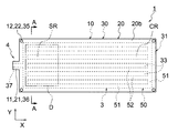
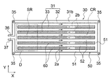
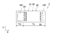
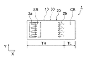
- FIG. 2 is a top view showing a vapor chamber according to the first embodiment of the present invention.
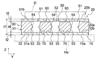
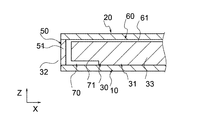
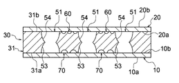
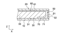
- FIG. 3 is a cross-sectional view taken along the line AA showing the vapor chamber of FIG.
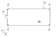
- FIG. 4 is a top view of the lower sheet of FIG.
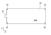
- FIG. 5 is a bottom view of the upper sheet of FIG.
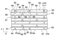
- FIG. 6 is a top view of the wick sheet of FIG.
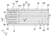
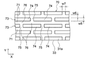
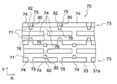
- FIG. 7 is a bottom view of the wick sheet of FIG.
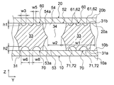
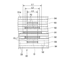
- FIG. 8A is a partially enlarged cross-sectional view of FIG.
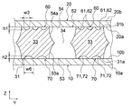
- FIG. 8B is a partially enlarged cross-sectional view showing another example of FIG. 8A.
- FIG. 8A is a partially enlarged cross-sectional view of FIG.
- FIG. 8B is a partially enlarged cross-sectional view showing another example of FIG. 8A.
- FIG. 8C is a partially enlarged cross-sectional view showing another example of FIG. 8A.
- FIG. 9 is a partially enlarged top view of the liquid flow path portion shown in FIG.
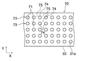
- FIG. 10 is a partially enlarged bottom view of the liquid storage portion shown in FIG. 7.
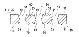
- FIG. 11 is a partial cross-sectional view taken along the line BB of FIG.
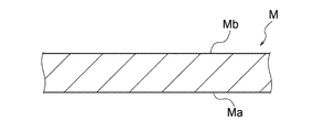
- FIG. 12 is a diagram for explaining a wick sheet preparation step in the method for manufacturing a vapor chamber according to the first embodiment.
- FIG. 13 is a diagram for explaining an etching process in the method for manufacturing a vapor chamber according to the first embodiment.
- FIG. 14 is a diagram for explaining a joining step in the method for manufacturing a vapor chamber according to the first embodiment.
- FIG. 15 is a partially enlarged top view showing the liquid flow path portion as a first modification.
- FIG. 16 is a partially enlarged bottom view showing a liquid storage portion as a first modification.
- FIG. 17 is a partially enlarged top view showing the liquid flow path portion as a second modification.
- FIG. 18 is a partially enlarged bottom view showing a liquid storage portion as a second modification.
- FIG. 19 is a partially enlarged bottom view showing a liquid storage portion as a third modification.
- FIG. 20 is a partially enlarged bottom view showing a liquid storage portion as a third modification.
- FIG. 21 is a partially enlarged bottom view showing a liquid storage portion as a third modification.
- FIG. 22 is a bottom view of the wick sheet of FIG. 3 as a fifth modification.
- FIG. 22 is a bottom view of the wick sheet of FIG. 3 as a fifth modification.
- FIG. 23 is a bottom view of the wick sheet of FIG. 3 as a sixth modification.
- FIG. 24 is a bottom view showing a wick sheet in the vapor chamber according to the second embodiment of the present invention.
- FIG. 25 is a partial cross-sectional view taken along the line CC of FIG. 24.
- FIG. 26 is a schematic view for explaining the state of reflux of the working fluid when the amount of heat generated by the electronic device is large in a general vapor chamber.
- FIG. 27 is a schematic view for explaining the state of reflux of the working fluid when the calorific value of the electronic device is small in a general vapor chamber.
- geometric conditions, physical properties, terms that specify the degree of geometric conditions or physical properties, numerical values indicating geometric conditions or physical properties, and the like are used. We will interpret it without being bound by the strict meaning. Then, these geometric conditions, physical properties, terms, numerical values, etc. shall be interpreted including the range in which similar functions can be expected. Examples of terms that specify geometric conditions include “length”, “angle”, “shape” or “arrangement”. Examples of terms that specify geometric conditions include “parallel”, “orthogonal”, “identical”, and the like. Further, in order to clarify the drawing, the shapes of a plurality of parts that can be expected to have the same function are regularly described.
- the shapes of the portions may be different from each other within the range in which the function can be expected.
- the boundary line indicating the joint surface between members is shown by a simple straight line for convenience, but it is not limited to a strict straight line and is within a range in which desired joining performance can be expected.
- the shape of the boundary line is arbitrary.
- the vapor chamber 1 in the present embodiment is housed in the housing H of the electronic device E together with the electronic device D that generates heat, and is a device for cooling the electronic device D.
- the electronic device E include mobile terminals such as mobile terminals and tablet terminals.
- the electronic device D include a central processing unit (CPU), a light emitting diode (LED), a power semiconductor, and the like.
- the electronic device D may be referred to as a device to be cooled.
- the electronic device E on which the vapor chamber 1 according to the present embodiment is mounted will be described by taking a tablet terminal as an example.
- the electronic device E includes a housing H, an electronic device D housed in the housing H, and a vapor chamber 1.
- a touch panel display TD is provided on the front surface of the housing H.
- the vapor chamber 1 is housed in the housing H and is arranged so as to be in thermal contact with the electronic device D.
- the vapor chamber 1 can receive the heat generated by the electronic device D when the electronic device E is used.
- the heat received by the vapor chamber 1 is released to the outside of the vapor chamber 1 via the working fluids 2a and 2b described later. In this way, the electronic device D is effectively cooled.
- the electronic device D corresponds to a central processing unit or the like.
- the vapor chamber 1 As shown in FIGS. 2 and 3, the vapor chamber 1 has a sealed space 3 in which the working fluids 2a and 2b are sealed, and the working fluids 2a and 2b in the sealed space 3 repeatedly undergo phase changes.
- the electronic device D described above is cooled.
- the working fluids 2a and 2b include pure water, ethanol, methanol, acetone and the like, and a mixed solution thereof.
- the working fluids 2a and 2b may have freeze-expandability. That is, the working fluids 2a and 2b may be fluids that expand during freezing.
- the freeze-expandable working fluids 2a and 2b include pure water, an aqueous solution obtained by adding an additive such as alcohol to pure water, and the like.
- the vapor chamber 1 includes a lower sheet 10, an upper sheet 20, and a wick sheet 30 for the vapor chamber.
- the lower sheet 10 is an example of the first sheet.
- the upper sheet 20 is an example of the second sheet.
- the wick sheet 30 for the vapor chamber is interposed between the lower sheet 10 and the upper sheet 20.
- the wick sheet for the vapor chamber is hereinafter simply referred to as the wick sheet 30.
- the lower sheet 10, the wick sheet 30, and the upper sheet 20 are laminated in this order.
- the vapor chamber 1 is generally formed in a thin flat plate shape.
- the planar shape of the vapor chamber 1 is arbitrary, but it may be rectangular as shown in FIG.
- the planar shape of the vapor chamber 1 may be, for example, a rectangle having one side of 1 cm and another side of 3 cm, or a square having one side of 15 cm, and the planar dimension of the vapor chamber 1 is arbitrary. ..
- the planar shape of the vapor chamber 1 is a rectangular shape having the X direction as a longitudinal direction, which will be described later, will be described.
- the lower sheet 10, the upper sheet 20, and the wick sheet 30 may have the same planar shape as the vapor chamber 1.
- the planar shape of the vapor chamber 1 is not limited to a rectangular shape, and may be any shape such as a circular shape, an elliptical shape, an L shape, or a T shape.
- the vapor chamber 1 has an evaporation region SR in which the working fluids 2a and 2b evaporate, and a condensing region CR in which the working fluids 2a and 2b condense.
- the evaporation region SR is a region that overlaps with the electronic device D in a plan view, and is a region to which the electronic device D is attached.
- the evaporation region SR can be arranged at any location in the vapor chamber 1. In the present embodiment, the evaporation region SR is formed on one side (left side in FIG. 2) of the vapor chamber 1 in the X direction.
- the heat from the electronic device D is transferred to the evaporation region SR, and the heat causes the liquid of the working fluid to evaporate in the evaporation region SR.
- the heat from the electronic device D can be transferred not only to the region where the electronic device D overlaps in a plan view but also to the periphery of the region where the electronic device D overlaps.
- the evaporation region SR includes a region overlapping the electronic device D and a region around the region in a plan view.
- the plan view is a state in which the vapor chamber 1 is viewed from a direction orthogonal to a surface that receives heat from the electronic device D and a surface that releases the received heat.
- the surface that receives heat corresponds to the second upper sheet surface 20b described later of the upper sheet 20.
- the surface that releases heat corresponds to the first lower sheet surface 10a described later of the lower sheet 10.
- a state in which the vapor chamber 1 is viewed from above or a state in which the vapor chamber 1 is viewed from below corresponds to a plan view.
- the gas of the working fluid is referred to as working vapor 2a
- the liquid of the working fluid is referred to as working fluid 2b.
- the condensed region CR is a region that does not overlap with the electronic device D in a plan view, and is a region in which the working steam 2a mainly releases heat and condenses.
- the condensed region CR can also be said to be a region around the evaporation region SR.
- the heat from the working steam 2a is released to the lower sheet 10 in the condensing region CR, and the working steam 2a is cooled and condensed in the condensing region CR.
- the vapor chamber 1 When the vapor chamber 1 is installed in the tablet terminal, the hierarchical relationship may be broken depending on the posture of the tablet terminal.
- the sheet that receives heat from the electronic device D is referred to as the above-mentioned upper sheet 20, and the sheet that releases the received heat is referred to as the above-mentioned lower sheet 10. Therefore, the configuration of the vapor chamber 1 will be described with the lower sheet 10 arranged on the lower side and the upper sheet 20 arranged on the upper side.
- the lower seat 10 has a first lower seat surface 10a provided on the side opposite to the wick seat 30 and a second seat surface 10a provided on the opposite side of the first lower seat surface 10a. It has a lower seat surface 10b.
- the second lower seat surface 10b is provided on the side of the wick seat 30.
- the lower sheet 10 may be formed flat as a whole.
- the lower sheet 10 may have a constant thickness as a whole.
- a housing member Ha that forms a part of the housing H described above is attached to the first lower seat surface 10a.
- the entire first lower seat surface 10a may be covered with the housing member Ha.
- alignment holes 12 may be provided at the four corners of the lower sheet 10.
- the upper sheet 20 includes a first upper sheet surface 20a provided on the side of the wick sheet 30 and a second upper sheet surface 20b provided on the side opposite to the first upper sheet surface 20a. ,have.
- the first upper seat surface 20a is provided on the side of the wick seat 30.
- the upper sheet 20 may be formed flat as a whole.
- the upper sheet 20 may have a constant thickness as a whole.
- the above-mentioned electronic device D is attached to the second upper seat surface 20b.
- alignment holes 22 may be provided at the four corners of the upper sheet 20.
- the wick sheet 30 includes a sheet main body 31, a steam flow path portion 50 provided in the sheet main body 31, a liquid flow path portion 60, and a liquid storage section 70.
- the seat body 31 has a first body surface 31a and a second body surface 31b provided on the side opposite to the first body surface 31a.
- the first main body surface 31a is arranged on the side of the lower sheet 10.
- the second main body surface 31b is arranged on the side of the upper sheet 20.
- the above-mentioned sealed space 3 is formed by the vapor flow path portion 50, the liquid flow path portion 60, and the liquid storage portion 70.
- the second lower sheet surface 10b of the lower sheet 10 and the first body surface 31a of the sheet body 31 may be diffusion-bonded.
- the second lower seat surface 10b and the first main body surface 31a may be permanently joined to each other.
- the first upper sheet surface 20a of the upper sheet 20 and the second body surface 31b of the sheet body 31 may be diffusion-bonded.
- the first upper sheet surface 20a and the second main body surface 31b may be permanently joined to each other.
- the lower sheet 10, the upper sheet 20, and the wick sheet 30 may be joined by other methods such as brazing as long as they can be permanently joined instead of diffusion joining.
- the term "permanently joined" is not bound by a strict meaning, and means that the sealed space 3 is joined to the extent that the sealing property can be maintained during the operation of the vapor chamber 1.
- the seat body 31 of the wick sheet 30 includes a frame body portion 32 and a plurality of land portions 33.
- the frame body portion 32 is formed in a rectangular frame shape in a plan view.
- the land portion 33 is provided in the frame body portion 32.
- the frame body portion 32 and the land portion 33 are portions where the material of the wick sheet 30 remains without being etched in the etching step described later.
- a steam flow path portion 50 is defined inside the frame body portion 32. That is, the working steam 2a flows inside the frame body portion 32 and around the land portion 33.
- the land portion 33 may extend in an elongated shape with the X direction as the longitudinal direction in a plan view.
- the planar shape of the land portion 33 may be an elongated rectangular shape.
- the X direction is an example of the first direction.
- the X direction corresponds to the left-right direction in FIG.
- the land portions 33 are spaced apart at equal intervals in the Y direction.
- the Y direction is an example of the second direction.
- the Y direction corresponds to the vertical direction in FIG.
- the land portions 33 may be arranged parallel to each other.
- the working steam 2a flows around each land portion 33 and is transported toward the condensed region CR. This prevents the flow of the working steam 2a from being obstructed.
- the width w1 of the land portion 33 (see FIG.
- the width w1 of the land portion 33 is the dimension of the land portion 33 in the Y direction.
- the width w1 means the dimension at the position where the penetration portion 34 described later exists in the thickness direction of the wick sheet 30.
- the frame body portion 32 and each land portion 33 are diffusion-bonded to the lower sheet 10 and diffusion-bonded to the upper sheet 20. This makes it possible to improve the mechanical strength of the vapor chamber 1.
- the first main body surface 31a and the second main body surface 31b of the seat main body 31 may be formed flat over the frame body portion 32 and each land portion 33.
- the steam flow path portion 50 is an example of a penetrating space penetrating the seat body 31.
- the steam flow path portion 50 is mainly a flow path through which the working steam 2a passes.
- the steam flow path portion 50 penetrates from the first main body surface 31a to the second main body surface 31b.
- the steam passage portion 50 in the present embodiment has a first steam passage 51 and a plurality of second steam passages 52.
- the first steam passage 51 is formed between the frame body portion 32 and the land portion 33.
- the first steam passage 51 is continuously formed inside the frame body portion 32 and outside the land portion 33.
- the plane shape of the first steam passage 51 is a rectangular frame shape.
- the second steam passage 52 is formed between the land portions 33 adjacent to each other.
- the planar shape of the second steam passage 52 is an elongated rectangular shape.
- the steam flow path portion 50 is divided into a first steam passage 51 and a plurality of second steam passages 52 by a plurality of land portions 33.
- the first steam passage 51 and the second steam passage 52 extend from the first main body surface 31a of the seat main body 31 to the second main body surface 31b.
- the first steam passage 51 and the second steam passage 52 are formed by a lower steam passage recess 53 provided on the first lower seat surface 10a and an upper steam passage recess 54 provided on the upper seat 20 surface 20b. Each is configured.
- the lower steam flow path recess 53 and the upper steam flow path recess 54 communicate with each other, and the first steam passage 51 and the second steam passage 52 of the steam flow path portion 50 are formed from the first main body surface 31a to the second main body surface 31b. Extends over.
- the lower steam flow path recess 53 is formed by etching from the first main body surface 31a of the wick sheet 30 in the etching step described later.
- the lower steam flow path recess 53 is formed in a concave shape on the first main body surface 31a.
- the lower steam flow path recess 53 has a curved wall surface 53a as shown in FIG. 8A.
- the wall surface 53a defines the lower steam flow path recess 53 and is curved so as to bulge toward the second main body surface 31b.
- Such a lower steam passage recess 53 constitutes a part (lower half) of the first steam passage 51 and a part (lower half) of the second steam passage 52.
- the upper steam flow path recess 54 is formed by etching from the second main body surface 31b of the wick sheet 30 in the etching process described later.
- the upper steam flow path recess 54 is formed in a concave shape on the second main body surface 31b.
- the upper steam flow path recess 54 has a curved wall surface 54a as shown in FIG. 8A.
- the wall surface 54a defines the upper steam flow path recess 54 and is curved so as to bulge toward the first main body surface 31a.
- Such an upper steam passage recess 54 constitutes a part (upper half) of the first steam passage 51 and a part (upper half) of the second steam passage 52.
- the wall surface 53a of the lower steam flow path recess 53 and the wall surface 54a of the upper steam flow path recess 54 are connected to form a penetrating portion 34.
- the wall surface 53a and the wall surface 54a are curved toward the penetrating portion 34, respectively.
- the lower steam flow path recess 53 and the upper steam flow path recess 54 communicate with each other.
- the planar shape of the penetrating portion 34 in the first steam passage 51 is a rectangular frame like the first steam passage 51.
- the planar shape of the penetrating portion 34 in the second steam passage 52 is an elongated rectangular shape similar to the second steam passage 52.
- the wall surface 53a of the lower steam flow path recess 53 and the wall surface 54a of the upper steam flow path recess 54 may merge and be defined by a ridgeline. As shown in FIG. 8A, the ridgeline may be formed so as to project inside the steam passages 51 and 52. In this penetrating portion 34, the plane area of the first steam passage 51 is minimized, and the plane area of the second steam passage 52 is minimized.
- the width w2 (see FIG. 8A) of such a penetrating portion 34 may be, for example, 400 ⁇ m to 1600 ⁇ m. Here, the width w2 of the penetrating portion 34 corresponds to the gap between the land portions 33 adjacent to each other in the Y direction.
- the position of the penetrating portion 34 in the Z direction may be an intermediate position between the first lower seat surface 10a and the upper seat 20 surface 20b.
- the position of the penetrating portion 34 may be a position shifted downward from the intermediate position, or may be a position shifted upward.
- the position of the penetrating portion 34 in the Z direction is arbitrary.
- the cross-sectional shapes of the first steam passage 51 and the second steam passage 52 are formed so as to include the penetrating portion 34 defined by the ridge line formed so as to project inward. , Not limited to this.
- the cross-sectional shape of the first steam passage 51 and the cross-sectional shape of the second steam passage 52 may be trapezoidal, rectangular, or barrel-shaped.
- the steam passage portion 50 including the first steam passage 51 and the second steam passage 52 configured in this way constitutes a part of the sealed space 3 described above.
- the steam flow path portion 50 according to the present embodiment is mainly defined by the lower sheet 10, the upper sheet 20, the frame body portion 32 and the land portion 33 of the sheet body 31 described above. There is.
- Each of the steam passages 51 and 52 has a relatively large flow path cross-sectional area through which the working steam 2a passes.
- FIG. 3 shows an enlarged view of the first steam passage 51, the second steam passage 52, and the like in order to clarify the drawing.
- the number and arrangement of these steam passages 51 and 52 are different from those in FIGS. 2, 6 and 7.
- a plurality of support portions for supporting the land portion 33 on the frame body portion 32 may be provided in the steam flow path portion 50. Further, a support portion for supporting the land portions 33 adjacent to each other may be provided. These support portions may be provided on both sides of the land portion 33 in the X direction, or may be provided on both sides of the land portion 33 in the Y direction.
- the support portion is preferably formed so as not to obstruct the flow of the working steam 2a diffusing the steam flow path portion 50. For example, it is arranged on one side of the first main body surface 31a and the second main body surface 31b of the sheet main body 31 of the wick sheet 30, and a space forming a steam flow path recess is formed on the other side. It may be. As a result, the thickness of the support portion can be made thinner than the thickness of the seat body 31, and the first steam passage 51 and the second steam passage 52 can be prevented from being divided in the X direction and the Y direction.
- alignment holes 35 may be provided at the four corners of the seat body 31 of the wick sheet 30.
- the vapor chamber 1 may further include an injection unit 4 for injecting the hydraulic fluid 2b into the sealed space 3 at one end edge in the X direction.
- the injection unit 4 is arranged on the side of the evaporation region SR.
- the injection portion 4 projects outward from the edge on the side of the evaporation region SR.
- the injection portion 4 may include a lower injection protrusion 11, an upper injection protrusion 21, and a wick sheet injection protrusion 36.
- the lower injection protrusion 11 is a portion constituting the lower sheet 10.
- the upper injection protrusion 21 is a portion constituting the upper sheet 20.
- the wick sheet injection protrusion 36 is a portion constituting the seat body 31.
- An injection flow path 37 is formed in the wick sheet injection protrusion 36. The injection flow path 37 extends from the first main body surface 31a of the sheet main body 31 to the second main body surface 31b, and penetrates the sheet main body 31 (more specifically, the wick sheet injection protrusion 36) in the Z direction. There is.
- the injection flow path 37 communicates with the steam flow path portion 50.
- the hydraulic fluid 2b is injected into the sealed space 3 through the injection flow path 37.
- the injection flow path 37 may communicate with the liquid flow path portion 60.
- the upper surface and the lower surface of the wick sheet injection protrusion 36 are formed flat.
- the upper surface of the lower injection protrusion 11 and the lower surface of the upper injection protrusion 21 are also formed flat.
- the planar shapes of the injection protrusions 11, 21, and 38 may be the same.
- the injection unit 4 is provided on one end edge of the pair of end edges in the X direction of the vapor chamber 1.
- the present invention is not limited to this, and the injection unit 4 can be provided at an arbitrary position.
- the injection flow path 37 provided in the wick sheet injection protrusion 36 does not have to penetrate the sheet body 31 as long as the hydraulic fluid 2b can be injected.
- the injection flow path 37 communicating with the steam flow path portion 50 can be formed by etching only from one of the first main body surface 31a and the second main body surface 31b of the sheet main body 31.
- the liquid flow path portion 60 is provided on the second main body surface 31b of the sheet main body 31 of the wick sheet 30.
- the liquid flow path portion 60 may be a flow path through which the hydraulic fluid 2b mainly passes.
- the liquid flow path portion 60 constitutes a part of the sealed space 3 described above.
- the liquid flow path portion 60 communicates with the vapor flow path portion 50.
- the liquid flow path portion 60 is configured as a capillary structure for transporting the working liquid 2b to the evaporation region SR.
- the liquid flow path portion 60 may be referred to as a wick.
- the liquid flow path portion 60 is provided on the second main body surface 31b of each land portion 33 of the wick sheet 30.
- the liquid flow path portion 60 may be formed over the entire second main body surface 31b of each land portion 33.
- the liquid flow path portion 60 may not be provided on the first main body surface 31a of each land portion 33.
- the liquid flow path portion 60 is an example of the first groove assembly. More specifically, the liquid flow path portion 60 includes a plurality of liquid flow path main flow grooves 61 and a plurality of liquid flow path connecting grooves 65.
- the liquid flow path mainstream groove 61 is an example of the first mainstream groove.
- the liquid flow path connecting groove 65 is an example of the first connecting groove.
- the liquid flow path main flow groove 61 and the liquid flow path connecting groove 65 are grooves through which the hydraulic fluid 2b passes.
- the liquid flow path connecting groove 65 communicates with the liquid flow path main flow groove 61.
- each liquid flow path mainstream groove 61 extends in the X direction.
- the liquid flow path main flow groove 61 mainly has a flow path cross-sectional area in which the hydraulic fluid 2b flows by capillary action.
- the flow path cross-sectional area of the liquid flow path main flow groove 61 is smaller than the flow path cross-sectional areas of the vapor passages 51 and 52.
- the liquid flow path main flow groove 61 is configured to transport the working liquid 2b condensed from the working vapor 2a to the evaporation region SR.
- the liquid flow path mainstream grooves 61 may be arranged at equal intervals in the Y direction orthogonal to the X direction.
- the liquid flow path main flow groove 61 is formed by etching from the second main body surface 31b of the sheet main body 31 of the wick sheet 30 in the etching step described later. As a result, the liquid flow path mainstream groove 61 has a curved wall surface 62 as shown in FIG. 8A.
- the wall surface 62 defines the liquid flow path main flow groove 61 and is curved so as to bulge toward the first main body surface 31a.
- the width w3 of the liquid flow path mainstream groove 61 may be, for example, 5 ⁇ m to 150 ⁇ m.
- the width w3 of the liquid flow path mainstream groove 61 means the dimension on the second main body surface 31b.
- the width w3 corresponds to the dimension in the Y direction.
- the depth h1 of the liquid flow path main flow groove 61 may be, for example, 3 ⁇ m to 150 ⁇ m.
- the depth h1 corresponds to the dimension in the Z direction.
- each liquid flow path connecting groove 65 extends in a direction different from the X direction.
- each liquid flow path connecting groove 65 extends in the Y direction.
- the liquid flow path connecting groove 65 is formed perpendicular to the liquid flow path main flow groove 61.
- Some liquid flow path connecting grooves 65 communicate with each other adjacent liquid flow path main flow grooves 61.
- the other liquid flow path connecting groove 65 communicates the first steam passage 51 or the second steam passage 52 with the liquid flow path main flow groove 61. That is, the liquid flow path connecting groove 65 extends from the edge of the land portion 33 in the Y direction to the liquid flow path main flow groove 61 adjacent to the edge. In this way, the first vapor passage 51 and the liquid flow path main flow groove 61 are communicated with each other, and the second vapor passage 52 and the liquid flow path main flow groove 61 are communicated with each other.
- the liquid flow path connecting groove 65 mainly has a flow path cross-sectional area through which the hydraulic fluid 2b flows by capillary action.
- the flow path cross-sectional area of the liquid flow path connecting groove 65 is smaller than the flow path cross-sectional areas of the vapor passages 51 and 52.
- the liquid flow path connecting grooves 65 may be arranged at equal intervals in the X direction.
- the liquid flow path connecting groove 65 is formed by etching like the liquid flow path main flow groove 61.
- the liquid flow path connecting groove 65 has a curved wall surface (not shown) similar to the liquid flow path main flow groove 61.
- the width w4 of the liquid flow path connecting groove 65 may be equal to the width w3 of the liquid flow path mainstream groove 61.
- the width w4 may be larger or smaller than the width w3.
- the width w4 corresponds to the dimension in the X direction.
- the depth of the liquid flow path connecting groove 65 may be equal to the depth h1 of the liquid flow path main flow groove 61.
- the depth of the liquid flow path connecting groove 65 may be deeper or shallower than the depth h1.
- a convex row 63 is provided between the liquid flow path mainstream grooves 61 adjacent to each other.
- Each convex row 63 includes a plurality of convex 64s arranged in the X direction.
- the convex portion 64 is an example of a liquid flow path protruding portion.
- the convex portion 64 is provided in the liquid flow path portion 60.
- the convex portion 64 protrudes from the sheet main body 31 and is in contact with the upper sheet 20.
- Each convex portion 64 is formed in a rectangular shape so that the X direction is the longitudinal direction in a plan view.
- a liquid flow path main flow groove 61 is interposed between the convex portions 64 adjacent to each other in the Y direction.
- a liquid flow path connecting groove 65 is interposed between the convex portions 64 adjacent to each other in the X direction.
- the liquid flow path connecting groove 65 extends in the Y direction and communicates with the liquid flow path main flow grooves 61 adjacent to each other in the Y direction. As a result, the hydraulic fluid 2b can flow between the main flow grooves 61 of the liquid flow path.
- the convex portion 64 is a portion where the material of the wick sheet 30 remains without being etched in the etching process described later.
- the planar shape of the convex portion 64 is rectangular.
- the planar shape of the convex portion 64 corresponds to the planar shape at the position of the second main body surface 31b of the sheet main body 31.
- the convex portions 64 are arranged in a staggered pattern. More specifically, the convex portions 64 of the convex portion rows 63 adjacent to each other in the Y direction are arranged so as to be offset from each other in the X direction. This amount of deviation may be half of the arrangement pitch of the convex portions 64 in the X direction.
- the width w5 of the convex portion 64 may be, for example, 5 ⁇ m to 500 ⁇ m.
- the width w5 of the convex portion 64 means the dimension on the second main body surface 31b.
- the width w5 corresponds to the dimension in the Y direction.
- the arrangement of the convex portions 64 is not limited to the staggered shape, and may be arranged in parallel. In this case, the convex portions 64 of the convex portion rows 63 adjacent to each other in the Y direction are also aligned in the X direction (see FIG. 19).
- the liquid flow path main flow groove 61 includes the liquid flow path intersection 66.
- the liquid flow path intersection 66 is an example of the first intersection.
- the liquid flow path intersection 66 is a portion of the liquid flow path main flow groove 61 that communicates with the liquid flow path connecting groove 65.
- the liquid flow path main flow groove 61 and the liquid flow path connecting groove 65 communicate in a T shape.
- the liquid flow path connecting groove 65 on the other side is concerned. It is possible to avoid communicating with the main flow groove 61 of the liquid flow path.
- the wall surface 62 of the liquid flow path main flow groove 61 can be prevented from being cut out on both sides, and one side of the wall surface 62 can remain.
- the capillary action can be imparted to the working liquid in the liquid flow path main flow groove 61. Therefore, it is possible to prevent the propulsive force of the working liquid 2b toward the evaporation region SR from decreasing at the liquid flow path intersection 66.
- the liquid storage unit 70 is provided on the first main body surface 31a of the sheet main body 31 of the wick sheet 30.
- the liquid storage unit 70 may be a portion that mainly stores the hydraulic fluid 2b.
- the liquid storage unit 70 constitutes a part of the sealed space 3 described above.
- the liquid storage unit 70 communicates with the vapor flow path portion 50 and also communicates with the liquid flow path portion 60 via the vapor flow path portion 50.
- the liquid storage unit 70 is provided on the first main body surface 31a of each land portion 33 of the wick sheet 30.
- the liquid storage unit 70 may be arranged on one side of the land unit 33 in the X direction.
- the liquid storage portion 70 may be formed on one side of the center of the land portion 33 in the X direction.
- the liquid storage unit 70 may be arranged on the side of the evaporation region SR, or may be arranged on the left side of the land unit 33 as shown in FIG. 7. More specifically, the liquid storage unit 70 is formed continuously from the edge on the side of the evaporation region SR to a predetermined position from the pair of edges of the land 33 in the X direction toward the other edge. ing. In FIG. 7, the liquid storage unit 70 is formed to a predetermined position from the left edge to the right edge.
- the liquid storage unit 70 may be arranged in the evaporation region SR.
- the present invention is not limited to this, and a part of the liquid storage unit 70 may protrude outside the evaporation region SR.
- the working liquid 2b stored in the liquid storage unit 70 is likely to evaporate due to the heat of the electronic device D.
- the liquid storage unit 70 may be arranged in a region overlapping with the electronic device D.
- the liquid storage unit 70 is an example of the second groove assembly. More specifically, the liquid storage unit 70 includes a plurality of liquid storage mainstream grooves 71 and a plurality of liquid storage connecting grooves 75.
- the liquid storage mainstream groove 71 is an example of the second mainstream groove.
- the liquid storage connecting groove 75 is an example of the second connecting groove.
- the liquid storage mainstream groove 71 and the liquid storage connecting groove 75 are grooves through which the hydraulic fluid 2b passes.
- the liquid storage connecting groove 75 communicates with the liquid storage mainstream groove 71.
- each liquid storage mainstream groove 71 extends in the X direction. As shown in FIGS. 7 and 11, the liquid storage mainstream groove 71 is continuously formed from the edge of the land portion 33 in the X direction on the side of the evaporation region SR to a predetermined position toward the edge on the other side. ing.
- the liquid storage mainstream groove 71 defines the X-direction range of the liquid storage unit 70.
- the liquid storage mainstream groove 71 mainly has a flow path cross-sectional area through which the hydraulic fluid 2b flows by capillary action.
- the flow path cross-sectional area of the liquid storage mainstream groove 71 is smaller than the flow path cross-sectional areas of the vapor passages 51 and 52.
- the flow path cross-sectional area of the liquid storage mainstream groove 71 may be larger than the flow path cross-sectional area of the liquid flow path mainstream groove 61 described above.
- the capillary force acting on the hydraulic fluid 2b in the liquid storage mainstream groove 71 may be smaller than the capillary force acting on the hydraulic fluid 2b in the liquid flow path mainstream groove 61. In this way, the liquid storage mainstream groove 71 can draw the hydraulic liquid 2b into the liquid storage unit 70 and secure the storage amount of the hydraulic liquid 2b.
- the liquid storage mainstream grooves 71 may be arranged at equal intervals in the Y direction orthogonal to the X direction.
- the liquid storage mainstream groove 71 is formed by etching from the first main body surface 31a of the sheet main body 31 of the wick sheet 30 in the etching step described later. As a result, the liquid storage mainstream groove 71 has a curved wall surface 72 as shown in FIG. 8A.
- the wall surface 72 defines the liquid storage mainstream groove 71 and is curved so as to bulge toward the second main body surface 31b.
- the width w6 of the liquid storage mainstream groove 71 may be larger than the width w3 of the liquid flow path mainstream groove 61 described above.
- the width w6 may be, for example, 10 ⁇ m to 250 ⁇ m.
- the width w6 of the liquid storage mainstream groove 71 means the dimension on the first main body surface 31a.
- the width w6 corresponds to the dimension in the Y direction.
- the depth h2 of the liquid storage mainstream groove 71 may be larger than the depth h1 of the liquid flow path mainstream groove 61 described above.
- the depth h2 may be, for example, 5 ⁇ m to 200 ⁇ m.
- the depth h2 corresponds to the dimension in the Z direction.
- each liquid storage connecting groove 75 extends in a direction different from the X direction.
- each liquid storage connecting groove 75 extends in the Y direction.
- the liquid storage connecting groove 75 is formed perpendicular to the liquid storage mainstream groove 71.
- Some liquid storage connecting grooves 75 communicate with each other adjacent liquid storage mainstream grooves 71.
- the other liquid storage connecting groove 75 communicates the first steam passage 51 or the second steam passage 52 with the liquid storage mainstream groove 71. That is, the liquid storage connecting groove 75 extends from the edge of the land portion 33 in the Y direction to the liquid storage mainstream groove 71 adjacent to the edge. In this way, the first vapor passage 51 and the liquid storage mainstream groove 71 are communicated with each other, and the second vapor passage 52 and the liquid storage mainstream groove 71 are communicated with each other.
- the liquid storage connecting groove 75 mainly has a flow path cross-sectional area through which the working liquid 2b flows by capillary action.
- the flow path cross-sectional area of the liquid storage connecting groove 75 is smaller than the flow path cross-sectional areas of the vapor passages 51 and 52.
- the flow path cross-sectional area of the liquid storage connecting groove 75 may be larger than the flow path cross-sectional area of the liquid flow path connecting groove 65 described above.
- the capillary force acting on the hydraulic fluid 2b in the liquid storage connecting groove 75 may be smaller than the capillary force acting on the hydraulic fluid 2b in the liquid flow path connecting groove 65. In this way, the liquid storage connecting groove 75 can draw the hydraulic liquid 2b into the liquid storage unit 70 and secure the storage amount of the hydraulic liquid 2b.
- the liquid storage connecting grooves 75 may be arranged at equal intervals in the X direction.
- the liquid storage connecting groove 75 is formed by etching like the liquid storage mainstream groove 71.
- the liquid storage connecting groove 75 has a curved wall surface (not shown) similar to the liquid storage mainstream groove 71.
- the width w7 of the liquid storage connecting groove 75 may be equal to the width w6 of the liquid storage mainstream groove 71.
- the width w7 may be larger or smaller than the width w6.
- the width w7 corresponds to the dimension in the X direction.
- the depth of the liquid storage connecting groove 75 may be equal to the depth h2 of the liquid storage mainstream groove 71.
- the depth of the liquid storage connecting groove 75 may be deeper or shallower than the depth h2.
- a convex row 73 is provided between the liquid storage mainstream grooves 71 adjacent to each other.
- Each convex row 73 includes a plurality of convex portions 74 arranged in the X direction.
- the convex portion 74 is an example of a liquid storage protruding portion.
- the convex portion 74 is provided in the liquid storage portion 70.
- the convex portion 74 protrudes from the sheet main body 31 and is in contact with the lower sheet 10.
- Each convex portion 74 is formed in a rectangular shape so that the X direction is the longitudinal direction in a plan view.
- a liquid storage mainstream groove 71 is interposed between the convex portions 74 adjacent to each other in the Y direction.
- a liquid storage connecting groove 75 is interposed between the convex portions 74 adjacent to each other in the X direction.
- the liquid storage connecting groove 75 extends in the Y direction and communicates with the liquid storage mainstream grooves 71 adjacent to each other in the Y direction. As a result, the hydraulic fluid 2b can flow between these liquid storage mainstream grooves 71.
- the convex portion 74 is a portion where the material of the wick sheet 30 remains without being etched in the etching step described later.
- the planar shape of the convex portion 74 is rectangular.
- the planar shape of the convex portion 74 corresponds to the planar shape at the position of the first main body surface 31a of the sheet main body 31.
- the convex portions 74 are arranged in a staggered pattern. More specifically, the convex portions 74 of the convex portion rows 73 adjacent to each other are arranged so as to be offset from each other in the X direction. This amount of deviation may be half of the arrangement pitch of the convex portions 74 in the X direction.
- the width w8 of the convex portion 74 may be, for example, 10 ⁇ m to 100 ⁇ m.
- the width w8 of the convex portion 74 means the dimension on the first main body surface 31a.
- the width w8 corresponds to the dimension in the Y direction.
- the arrangement of the convex portions 74 is not limited to the staggered shape, and may be arranged in parallel. In this case, the convex portions 74 of the convex portion rows 73 adjacent to each other in the Y direction are also aligned in the X direction (see FIG. 19).
- the width w6 of the liquid storage mainstream groove 71 may be larger than w3 of the liquid flow path mainstream groove 61.
- the width w6 corresponds to the gap between a pair of convex portions 74 adjacent to each other in the Y direction.
- the width w6 of the liquid storage mainstream groove 71 may be smaller than the width w2 of the penetrating portion 34.
- the width w2 corresponds to a gap between a pair of land portions 33 adjacent to each other in the Y direction.
- the flow path cross-sectional area of the liquid storage mainstream groove 71 of the liquid storage section 70 is larger than the flow path cross-sectional area of the liquid flow path mainstream groove 61 of the liquid flow path section 60. ing.
- the width w6 of the liquid storage mainstream groove 71 is larger than the width w3 of the liquid flow path mainstream groove 61, and the liquid storage mainstream groove 71
- the depth h2 of the liquid flow path is larger than the depth h1 of the main flow groove 61 of the liquid flow path.
- the present invention is not limited to this, and the relationship between the width and the depth is arbitrary as long as the flow path cross-sectional area of the liquid storage mainstream groove 71 is larger than the flow path cross-sectional area of the liquid flow path mainstream groove 61.
- the width w6 is larger than the width w3
- the depth h2 may be equal to the depth h1.
- the flow path cross-sectional area of the liquid storage mainstream groove 71 can be made larger than the flow path cross-sectional area of the liquid flow path mainstream groove 61.
- the width w6 may be equal to the width w3.
- the flow path cross-sectional area of the liquid storage mainstream groove 71 can be made larger than the flow path cross-sectional area of the liquid flow path mainstream groove 61.
- the channel cross-sectional area of the groove in the present specification corresponds to the area occupied by the groove in the cross section along the direction orthogonal to the direction in which the groove extends.
- the flow path cross-sectional area of the liquid flow path mainstream groove 61 corresponds to the area occupied by the groove 61 (or the space defined by the wall surface 62 of the groove 61) in the cross section of the liquid flow path mainstream groove 61 along the Y direction.
- the number of the liquid storage mainstream grooves 71 provided in the land portion 33 may be smaller than the number of the liquid flow path mainstream grooves 61 provided in the land portion 33.
- the land portion 33 extends in the X direction and has an elongated rectangular shape.
- the width of the land portion 33 on the first main body surface 31a is equal to the width of the land portion 33 on the second main body surface 31b.
- the flow path cross-sectional area of the liquid storage mainstream groove 71 can be made larger than the flow path cross-sectional area of the liquid flow path mainstream groove 61.
- the liquid storage mainstream groove 71 includes the liquid storage intersection 76.
- the liquid storage intersection 76 is an example of the second intersection.
- the liquid storage intersection 76 is a portion of the liquid storage mainstream groove 71 that communicates with the liquid storage connecting groove 75.
- the liquid storage mainstream groove 71 and the liquid storage connecting groove 75 communicate in a T shape.
- the liquid storage connecting groove 75 on the other side becomes the liquid storage mainstream groove. It is possible to avoid communicating with 71.
- the materials constituting the lower sheet 10, the upper sheet 20 and the wick sheet 30 are not particularly limited as long as they are materials having good thermal conductivity, but the lower sheet 10, the upper sheet 20 and the wick sheet 30 are not particularly limited. May include, for example, copper or a copper alloy.
- the thermal conductivity of each of the sheets 10, 20, and 30 can be increased, and the heat dissipation efficiency of the vapor chamber 1 can be increased.
- corrosion can be prevented. If desired heat dissipation efficiency can be obtained and corrosion can be prevented, other metal materials such as aluminum and titanium, and other metal alloy materials such as stainless steel can be used for these sheets 10, 20 and 30.
- the thickness t1 of the vapor chamber 1 shown in FIG. 3 may be, for example, 100 ⁇ m to 1000 ⁇ m.
- the steam flow path portion 50 can be appropriately secured. Therefore, the function of the vapor chamber 1 can be appropriately exerted.
- the thickness t1 to 1000 ⁇ m or less it is possible to prevent the vapor chamber 1 from becoming thicker.
- the thickness t2 of the lower sheet 10 may be, for example, 6 ⁇ m to 100 ⁇ m. By setting the thickness t2 of the lower sheet 10 to 6 ⁇ m or more, the mechanical strength of the lower sheet 10 can be ensured. On the other hand, by setting the thickness t2 of the lower sheet 10 to 100 ⁇ m or less, it is possible to prevent the thickness t1 of the vapor chamber 1 from becoming thick.
- the thickness t3 of the upper sheet 20 may be set in the same manner as the thickness t2 of the lower sheet 10. The thickness t3 of the upper sheet 20 and the thickness t2 of the lower sheet 10 may be different.
- the thickness t4 of the wick sheet 30 may be, for example, 50 ⁇ m to 400 ⁇ m.
- the steam flow path portion 50 can be appropriately secured. Therefore, the function of the vapor chamber 1 can be appropriately exerted.
- the thickness is set to 400 ⁇ m or less, it is possible to prevent the vapor chamber 1 from becoming thicker t1.
- FIGS. 12 to 14 the cross section similar to the cross-sectional view of FIG. 3 is shown.
- a flat metal material sheet M is prepared as a preparatory step.
- the metal material sheet M includes a first material surface Ma and a second material surface Mb.
- the metal material sheet M may be formed of a rolled material having a desired thickness.
- the metal material sheet M is etched from the first material surface Ma and the second material surface Mb.
- the vapor flow path portion 50, the liquid flow path portion 60, and the liquid storage portion 70 are formed on the metal material sheet M.
- a patterned resist film (not shown) is formed on the first material surface Ma and the second material surface Mb of the metal material sheet M by photolithography technology. Subsequently, the first material surface Ma and the second material surface Mb of the metal material sheet M are etched through the openings of the patterned resist film. As a result, the first material surface Ma and the second material surface Mb of the metal material sheet M are etched in a pattern, and the vapor flow path portion 50, the liquid flow path portion 60, and the liquid storage portion 70 as shown in FIG. 13 are etched. Is formed.
- the etching solution for example, an iron chloride-based etching solution such as a ferric chloride aqueous solution or a copper chloride-based etching solution such as a copper chloride aqueous solution can be used.
- the first material surface Ma and the second material surface Mb of the metal material sheet M may be etched at the same time.
- the present invention is not limited to this, and the etching of the first material surface Ma and the second material surface Mb may be performed as separate steps.
- the vapor flow path portion 50, the liquid flow path portion 60, and the liquid storage portion 70 may be formed by etching at the same time, or may be formed by separate steps.
- etching step by etching the first material surface Ma and the second material surface Mb of the metal material sheet M, a predetermined outer contour shape as shown in FIGS. 6 and 7 can be obtained. That is, the edge of the wick sheet 30 is formed.
- the wick sheet 30 according to the present embodiment can be obtained.
- the lower sheet 10 and the upper sheet 20 may be made of a rolled material having a desired planar shape and a desired thickness.
- the lower sheet 10, the wick sheet 30, and the upper sheet 20 are laminated in this order.
- the first main body surface 31a of the wick sheet 30 is overlapped with the second lower seat surface 10b of the lower sheet 10
- the first upper seat surface 20a of the upper sheet 20 is overlapped with the second main body surface 31b of the wick sheet 30.
- the alignment holes 12 of the lower sheet 10, the alignment holes 35 of the wick sheet 30, and the alignment holes 22 of the upper sheet 20 are used to align the sheets 10, 20, and 30 respectively.
- the lower sheet 10, the wick sheet 30, and the upper sheet 20 are temporarily fixed.
- these sheets 10, 20, and 30 may be temporarily fixed by spot resistance welding, or these sheets 10, 20, and 30 may be temporarily fixed by laser welding.
- Diffusion bonding means that the lower sheet 10, the wick sheet 30, and the upper sheet 20 are pressurized and heated in the stacking direction in a controlled atmosphere such as in a vacuum or an inert gas to generate atoms on the bonding surface. It is a method of joining using diffusion.
- a controlled atmosphere such as in a vacuum or an inert gas to generate atoms on the bonding surface. It is a method of joining using diffusion.
- Diffusion bonding heats the materials of the sheets 10, 20, and 30 to a temperature close to the melting point, but since it is lower than the melting point, it is possible to prevent the sheets 10, 20, and 30 from melting and deforming.
- the frame body portion 32 of the wick sheet 30 and the first main body surface 31a of each land portion 33 are diffusively joined to the second lower sheet surface 10b of the lower sheet 10. Further, the frame body portion 32 of the wick sheet 30 and the second main body surface 31b of each land portion 33 are diffusion-bonded to the first upper sheet surface 20a of the upper sheet 20 surface. In this way, the sheets 10, 20, and 30 are diffusion-bonded to have a vapor flow path portion 50, a liquid flow path portion 60, and a liquid storage section 70 between the lower sheet 10 and the upper sheet 20. A sealed space 3 is formed. At this stage, the injection flow path 37 described above is not sealed in the sealed space 3.
- the lower injection protrusion 11 of the lower sheet 10 and the wick sheet injection protrusion 36 of the wick sheet 30 are diffusively joined. Further, the wick sheet injection protrusion 36 and the upper injection protrusion 21 of the upper sheet 20 are diffusively joined.
- the working liquid 2b is injected from the injection portion 4 into the sealed space 3.
- the working liquid 2b may be injected in an injection amount larger than the total volume of the space composed of each liquid flow path main flow groove 61 and each liquid flow path connecting groove 65 of the liquid flow path portion 60.
- the injection flow path 37 described above is sealed.
- the injection unit 4 may be irradiated with a laser beam so that the injection unit 4 is partially melted to seal the injection flow path 37.
- the communication between the sealed space 3 and the outside is cut off, and the sealed space 3 in which the hydraulic fluid 2b is sealed can be obtained. Therefore, the hydraulic fluid 2b in the sealed space 3 is prevented from leaking to the outside.
- the injection portion 4 may be crimped (or pressed to be plastically deformed) or brazed.
- the vapor chamber 1 according to the present embodiment can be obtained.
- the vapor chamber 1 obtained as described above is installed in the housing H of a mobile terminal or the like.
- An electronic device D such as a CPU, which is a device to be cooled, is attached to the second upper sheet surface 20b of the upper sheet 20.
- the working liquid 2b in the sealed space 3 adheres to the wall surface of the sealed space 3 due to its surface tension.
- the hydraulic fluid 2b includes the wall surface 53a of the lower vapor flow path recess 53, the wall surface 54a of the upper vapor flow path recess 54, the wall surface 62 of the liquid flow path main flow groove 61 of the liquid flow path portion 60, and the liquid flow. It adheres to the wall surface of the road connecting groove 65.
- the working liquid 2b may also adhere to the portion of the second lower sheet surface 10b of the lower sheet 10 exposed to the lower vapor flow path recess 53. Further, the working liquid 2b may also adhere to the portion of the first upper sheet surface 20a of the upper sheet 20 that is exposed to the upper vapor flow path recess 54, the liquid flow path main flow groove 61, and the liquid flow path connecting groove 65.
- the working fluid 2b existing in the evaporation region SR receives heat from the electronic device D.
- the received heat is absorbed as latent heat
- the working liquid 2b evaporates
- the working vapor 2a is generated.
- Most of the generated working steam 2a diffuses in the lower steam flow path recess 53 and the upper steam flow path recess 54 constituting the sealed space 3 (see the solid line arrow in FIG. 6).
- the working steam 2a in each of the steam flow path recesses 53 and 54 is separated from the evaporation region SR.
- Most of the working steam 2a is transported to the condensing region CR where the temperature is relatively low.
- the working steam 2a mainly dissipates heat to the lower sheet 10 and is cooled.
- the heat received by the lower sheet 10 from the working steam 2a is transferred to the outside air via the housing member Ha (see FIG. 3).
- the working steam 2a dissipates heat to the lower sheet 10 in the condensed region CR.
- the working vapor 2a loses the latent heat absorbed in the evaporation region SR and condenses, and the working liquid 2b is generated.
- the generated hydraulic fluid 2b adheres to the wall surfaces 53a and 54a of the vapor flow path recesses 53 and 54, the second lower sheet surface 10b of the lower sheet 10, and the first upper sheet surface 20a of the upper sheet 20.
- the working liquid 2b continues to evaporate in the evaporation region SR.
- the working liquid 2b in the region other than the evaporation region SR (that is, the condensation region CR) in the liquid flow path portion 60 is transported toward the evaporation region SR by the capillary action of each liquid flow path mainstream groove 61. (See the dashed arrow in FIG. 6).
- the hydraulic fluid 2b adhering to the wall surfaces 53a and 54a, the second lower seat surface 10b, and the first upper seat surface 20a moves to the liquid flow path portion 60.
- the working liquid 2b passes through the liquid flow path connecting groove 65 and enters the liquid flow path main flow groove 61. In this way, the working liquid 2b is filled in each liquid flow path main flow groove 61 and each liquid flow path connecting groove 65.
- the filled hydraulic fluid 2b obtains a propulsive force toward the evaporation region SR by the capillary action of each liquid flow path mainstream groove 61. In this way, the working fluid 2b is smoothly transported toward the evaporation region SR.
- each liquid flow path main flow groove 61 communicates with another adjacent liquid flow path main flow groove 61 via the corresponding liquid flow path connecting groove 65.
- the hydraulic fluid 2b in each liquid flow path main flow groove 61 is imparted with a capillary action, and the hydraulic fluid 2b is smoothly transported toward the evaporation region SR.
- a part of the working liquid 2b condensed in the condensed region CR is transported not to the liquid flow path portion 60 but to the liquid storage portion 70 provided on the first main body surface 31a of the wick sheet 30. More specifically, a part of the working liquid 2b adhering to the respective wall surfaces 53a and 54a, the second lower seat surface 10b and the first upper seat surface 20a passes through the liquid storage connecting groove 75 and is the mainstream of liquid storage. Enter the groove 71. In this way, the working liquid 2b is filled in each liquid storage mainstream groove 71 and each liquid storage connecting groove 75. Therefore, the working liquid 2b obtains propulsive force by the capillary action of each liquid storage mainstream groove 71 and the capillary action of each liquid storage connecting groove 75, and moves smoothly toward the inside of the liquid storage section 70.
- the working liquid 2b that has reached the evaporation region SR by the liquid flow path portion 60 receives heat again from the electronic device D and evaporates.
- the working vapor 2a evaporated from the working liquid 2b moves through the liquid flow path connecting groove 65 in the evaporation region SR to the lower steam flow path recess 53 and the upper steam flow path recess 54 having a large flow path cross-sectional area.
- the working steam 2a diffuses in the steam flow path recesses 53 and 54.
- the liquid storage unit 70 is arranged in the evaporation region SR.
- the working liquid 2b in the liquid storage unit 70 also evaporates in the same manner and diffuses in the vapor flow path recesses 53 and 54.
- the working fluids 2a and 2b reflux in the sealed space 3 while repeating phase changes, that is, evaporation and condensation.
- the heat of the electronic device D is transported and released.
- the electronic device D is cooled.
- the hydraulic fluid 2b in the evaporation region SR does not evaporate and stays filled in the liquid flow path main flow groove 61 and the liquid flow path connecting groove 65 of the liquid flow path portion 60. .. Therefore, the working liquid 2b in the condensing region CR remains without being transported toward the evaporation region SR.
- a part of the hydraulic fluid 2b in the liquid flow path portion 60 flows through the wall surface 53a of the lower vapor flow path recess 53 or the wall surface 54a of the upper steam flow path recess 54, and flows through the liquid storage main flow groove 71 and the liquid storage main flow groove 71 of the liquid storage section 70. Move to the liquid storage connecting groove 75.
- the working fluid 2b is filled and stays in these grooves 71 and 75.
- the amount of the hydraulic fluid 2b sealed in the sealed space 3 is larger than the total volume of the space composed of the liquid flow path main flow groove 61 and the liquid flow path connecting groove 65, a part of the hydraulic fluid 2b is used. , The liquid storage mainstream groove 71 and the liquid storage connecting groove 75 are easily filled. Therefore, the working liquid 2b can be dispersed and stayed not only in the liquid flow path portion 60 but also in the liquid storage portion 70.
- the electronic device E equipped with the vapor chamber 1 is placed in a temperature environment lower than the freezing point of the working fluids 2a and 2b, and the working liquid 2b in the liquid flow path portion 60 freezes and expands. Even if there is, the expansion force of the working fluids 2a and 2b is weakened. As a result, the upper sheet 20 is suppressed from being deformed by the force due to the expansion. Therefore, it is possible to prevent the flatness of the second upper sheet surface 20b of the upper sheet 20 to which the electronic device D is attached from being lowered, and a gap is formed between the second upper sheet surface 20b and the electronic device D. Can be suppressed.
- the liquid flow path portion 60 is provided on the second main body surface 31b of the sheet main body 31 of the wick sheet 30, and the first main body surface is located on the side opposite to the second main body surface 31b.
- a liquid storage unit 70 is provided in 31a.
- the flow path cross-sectional area of the liquid storage mainstream groove 71 of the liquid storage section 70 is larger than the flow path cross-sectional area of the liquid flow path mainstream groove 61 of the liquid flow path section 60.
- the expansion force acting on the upper sheet 20 can be reduced. In this case, it is possible to prevent the upper sheet 20 from being deformed. Further, even when the hydraulic fluid 2b in the liquid storage unit 70 freezes and expands, the expansion force acting on the lower sheet 10 can be reduced. In this case, it is possible to prevent the lower sheet 10 from being deformed. As a result, the deformation of the vapor chamber 1 can be suppressed, and the performance deterioration of the vapor chamber 1 can be suppressed. Further, while the electronic device D is generating heat, the working liquid 2b in the liquid storage unit 70 can evaporate by receiving the heat from the electronic device D. Therefore, the heat of the electronic device D can be further diffused, and the cooling efficiency of the electronic device D can be improved.
- the liquid flow path portion 60 is provided on the second main body surface 31b of the sheet main body 31 of the wick sheet 30, and the first main body surface 31a located on the side opposite to the second main body surface 31b. Is provided with a liquid storage unit 70.
- the flow path cross-sectional area of the liquid storage mainstream groove 71 of the liquid storage section 70 is larger than the flow path cross-sectional area of the liquid flow path mainstream groove 61 of the liquid flow path section 60.
- the capillary force acting on the hydraulic fluid 2b in the liquid storage mainstream groove 71 can be made smaller than the capillary force acting on the hydraulic fluid 2b in the liquid flow path mainstream groove 61.
- the amount of movement of the working liquid 2b to the liquid storage unit 70 can be reduced. Therefore, it is possible to suppress a decrease in the transport function of the working liquid 2b to the evaporation region SR, and it is possible to suppress a decrease in the heat transport efficiency.
- the total space composed of each liquid storage mainstream groove 71 is totaled. The volume can be increased. Therefore, the amount of the hydraulic fluid 2b stored by the liquid storage unit 70 can be increased while the electronic device D stops generating heat.
- the width of the liquid storage mainstream groove 71 is larger than the width of the liquid flow path mainstream groove 61.
- the flow path cross-sectional area of the liquid storage mainstream groove 71 can be made larger than the flow path cross-sectional area of the liquid flow path mainstream groove 61. Therefore, it is possible to suppress a decrease in heat transport efficiency and increase the storage amount of the hydraulic fluid 2b.
- the depth of the liquid storage mainstream groove 71 is larger than the depth of the liquid flow path mainstream groove 61.
- the flow path cross-sectional area of the liquid storage mainstream groove 71 can be made larger than the flow path cross-sectional area of the liquid flow path mainstream groove 61. Therefore, it is possible to suppress a decrease in heat transport efficiency and increase the storage amount of the hydraulic fluid 2b.
- each land portion 33 is provided with a liquid flow path portion 60 and a liquid storage portion 70, and the number of liquid storage mainstream grooves 71 provided in the land portion 33 is the number of the land portion 33.
- the number is less than the number of the main flow grooves 61 of the liquid flow path provided in.
- the flow path cross-sectional area of the liquid storage mainstream groove 71 can be made larger than the flow path cross-sectional area of the liquid flow path mainstream groove 61. Therefore, it is possible to suppress a decrease in heat transport efficiency and increase the storage amount of the hydraulic fluid 2b.
- a liquid flow path portion 60 through which the hydraulic fluid 2b passes is provided on the second main body surface 31b of the seat main body 31 of the wick sheet 30, and is located on the side opposite to the second main body surface 31b.
- a liquid storage unit 70 is provided on the first main body surface 31a.
- the liquid storage unit 70 is arranged in the evaporation region SR in a plan view.
- the expansion force acting on the upper sheet 20 can be reduced. In this case, it is possible to prevent the upper sheet 20 from being deformed. Further, even when the hydraulic fluid 2b in the liquid storage unit 70 freezes and expands, the expansion force acting on the lower sheet 10 can be reduced. In this case, it is possible to prevent the lower sheet 10 from being deformed. As a result, the deformation of the vapor chamber 1 can be suppressed, and the performance deterioration of the vapor chamber 1 can be suppressed.
- the working liquid 2b in the liquid storage unit 70 can be evaporated by receiving the heat from the electronic device D. Therefore, the heat of the electronic device D can be further diffused, and the cooling efficiency of the electronic device D can be improved.
- a plurality of convex portions 74 projecting from the sheet main body 31 of the wick sheet 30 and abutting on the lower sheet 10 are provided in the liquid storage unit 70.
- the gap between the pair of convex portions 74 adjacent to each other (corresponding to the width w6 of the liquid storage mainstream groove 71) is larger than the width of the liquid flow path mainstream groove 61 of the liquid flow path portion 60.
- the capillary force acting on the hydraulic fluid 2b in the liquid storage unit 70 can be made smaller than the capillary force acting on the hydraulic fluid 2b in the liquid flow path portion 60 (inside the liquid flow path mainstream groove 61).
- the amount of movement of the working liquid 2b to the liquid storage unit 70 can be reduced. Therefore, it is possible to suppress a decrease in the transport function of the working liquid 2b to the evaporation region SR, and it is possible to suppress a decrease in the heat transport efficiency.
- each liquid storage mainstream groove 71 and each liquid storage connecting groove 75 of the liquid storage section 70 are formed. The total volume of space created can be increased. Therefore, the amount of the hydraulic fluid 2b stored by the liquid storage unit 70 can be increased while the electronic device D stops generating heat.
- the liquid storage unit 70 is located between the convex portions 74 adjacent to each other in the Y direction orthogonal to the X direction, which is the direction in which the liquid flow path main flow groove 61 of the liquid flow path unit 60 extends. It has a liquid storage mainstream groove 71 provided, and the liquid storage mainstream groove 71 extends in the X direction. After the electronic device D stops generating heat, the hydraulic fluid 2b flows roughly in the X direction from the condensation region CR toward the evaporation region SR, but the hydraulic fluid 2b that reaches the liquid storage unit 70 flows into the liquid storage mainstream. It can easily enter the groove 71.
- the hydraulic fluid 2b can be quickly drawn into the liquid storage unit 70, and the stored amount of the hydraulic fluid 2b can be rapidly increased.
- the ambient temperature of the vapor chamber 1 drops sharply, the working liquid 2b can be quickly drawn into the liquid storage unit 70.
- the expansion force acting on the upper sheet 20 and the lower sheet 10 when the hydraulic fluid 2b is frozen can be effectively reduced. Therefore, the deformation of the vapor chamber 1 can be effectively suppressed.
- the gap between the pair of convex portions 74 adjacent to each other is smaller than the gap between the pair of land portions 33 adjacent to each other (corresponding to the width w2 of the penetrating portion 34). ing.
- the capillary force can act on the working liquid 2b in the liquid storage unit 70. Therefore, the hydraulic fluid 2b can be drawn into the liquid storage unit 70, and the hydraulic fluid 2b can be stored while the electronic device D stops heat generation.
- the liquid storage unit 70 is provided on the first main body surface 31a of each land unit 33.
- the working liquid 2b can be dispersed and stored in each liquid storage unit 70. Therefore, even when the hydraulic fluid 2b in the liquid flow path portion 60 freezes and expands in a temperature environment lower than the freezing point of the hydraulic fluid 2b, the deformation of the upper sheet 20 can be further suppressed. Further, even when the working liquid 2b in the liquid storage unit 70 freezes and expands, the deformation of the lower sheet 10 can be further suppressed.
- the liquid storage unit 70 is arranged on one side of the land unit 33 in the X direction.
- the liquid storage unit 70 can be arranged in the evaporation region SR. Therefore, while the electronic device D generates heat, the hydraulic fluid 2b in the liquid storage unit 70 can evaporate, and the heat of the electronic device D can be further diffused. As a result, the cooling efficiency of the electronic device D can be improved.
- the communication portion 80 may include a communication recess 81 provided on the wall surface of the steam flow path portion 50.
- the communication recess 81 may extend from the liquid flow path portion 60 to the liquid storage portion 70.
- a communication recess 81 extending in the Z direction is provided along the wall surface 53a of the lower steam flow path recess 53 and the wall surface 54a of the upper steam flow path recess 54.
- the communication recess 81 may extend to at least one of the liquid flow path connecting groove 65 of the liquid flow path portion 60 and the liquid storage connecting groove 75 of the liquid storage section 70.
- one end of the communication recess 81 extends to the liquid flow path connecting groove 65, and the other end of the communication recess 81 extends to the liquid storage connecting groove 75.
- the communication recess 81 may not be communicated with the liquid flow path connecting groove 65, or may not be communicated with the liquid storage connecting groove 75. Further, the communication recess 81 may not be communicated with either the liquid flow path connecting groove 65 or the liquid storage connecting groove 75.
- the cross-sectional shape of the flow path of the communication recess 81 may be rectangular as shown in FIGS. 15 and 16, or may be formed into a curved shape such as a semicircular shape or a semi-elliptical shape. The cross-sectional shape of the flow path of the communication recess 81 corresponds to the shape in a plan view.
- the width w9 of the communication recess 81 may be larger than the width w4 of the liquid flow path connecting groove 65 (see FIG. 9).
- the width w9 corresponds to the dimension in the X direction.
- the capillary force acting on the hydraulic fluid 2b in the communication recess 81 can be made smaller than the capillary force acting on the hydraulic fluid 2b in the liquid flow path connecting groove 65.
- the communication recess 81 is formed so as to cut out the convex portion 64.
- the width w9 of the communication recess 81 may be smaller than the width w7 (see FIG.
- the width w9 of the communication recess 81 may be, for example, 20 ⁇ m to 300 ⁇ m.
- the width w9 of the communication recess 81 means the dimension of the wick sheet 30 on the second main body surface 31b.
- the electronic device D stops heat generation, a part of the hydraulic fluid 2b in the liquid flow path portion 60 moves to the liquid storage portion 70 through the communication portion 80. it can. As a result, the amount of movement of the hydraulic fluid 2b from the liquid flow path portion 60 to the liquid storage portion 70 can be increased, and the amount of the hydraulic fluid 2b stored in the liquid storage portion 70 can be increased.
- the communication portion 80 includes a communication recess 81 provided on the wall surface of the vapor flow path portion 50 and extending from the liquid flow path portion 60 to the liquid storage portion 70.
- the flow path resistance of the hydraulic fluid 2b from the liquid flow path portion 60 to the liquid storage section 70 can be reduced. Therefore, the amount of the hydraulic fluid 2b staying in the liquid flow path portion 60 can be reduced. Even when the hydraulic fluid 2b in the liquid flow path portion 60 freezes and expands, the expansion force can be weakened. Further, even when the hydraulic fluid 2b in the liquid storage unit 70 freezes and expands, the expansion force can be weakened.
- the communication recess 81 extends to the liquid flow path connecting groove 65 and the liquid storage connecting groove 75, so that the hydraulic fluid 2b flows from the liquid flow path portion 60 to the liquid storage portion 70. Road resistance can be further reduced.
- the communication portion 80 penetrates the sheet body 31 and the liquid flow path portion 60, as in the second modification shown in FIGS. 17 and 18. It may include a through hole 82 extending from the liquid storage unit 70.
- the through hole 82 is not inside the wall surface 53a of the lower steam flow path recess 53 or the wall surface 54a of the upper steam flow path recess 54, but inside the land portion 33 in a plan view. positioned.
- the through hole 82 is formed at a position so as not to be cut out by the wall surface 53a of the lower steam flow path recess 53 and the wall surface 54a of the upper steam flow path recess 54.
- the through hole 82 has a closed contour shape in a plan view. 17 and 18 show an example in which the through hole 82 is formed in a rectangular shape.
- the planar shape of the through hole 82 may be any shape such as a circular shape.
- the through hole 82 may extend to at least one of the liquid flow path intersection 66 of the liquid flow path 60 and the liquid storage intersection 76 of the liquid storage 70.
- one end of the through hole 82 extends to the liquid flow path intersection 66 and is located at the liquid flow path intersection 66 described above.
- the other end of the through hole 82 extends to the liquid storage intersection 76.
- the through hole 82 does not have to be communicated with the liquid flow path intersection 66 as long as it is communicated with the liquid flow path main flow groove 61 or the liquid flow path connecting groove 65.
- the through hole 82 may not be communicated with the liquid storage intersection 76 as long as it is communicated with the liquid storage mainstream groove 71 or the liquid storage connecting groove 75.
- the cross-sectional shape of the flow path of the through hole 82 may be rectangular as shown in FIGS. 17 and 18, or may be formed in a curved shape such as a circular shape or an elliptical shape.
- the cross-sectional shape of the flow path of the through hole 82 corresponds to the shape in a plan view.
- the width w10 of the through hole 82 may be larger than the width w4 of the liquid flow path connecting groove 65 (see FIG. 9).
- the width w10 corresponds to the dimension in the X direction.
- the capillary force acting on the hydraulic fluid 2b in the through hole 82 can be made smaller than the capillary force acting on the hydraulic fluid 2b in the liquid flow path connecting groove 65.
- the through hole 82 is formed so as to cut out the convex portion 64.
- the width w10 of the through hole 82 may be smaller than the width w7 (see FIG. 10) of the liquid storage connecting groove 75.
- the width w10 of the through hole 82 may be, for example, 10 ⁇ m to 100 ⁇ m.
- the width w10 of the through hole 82 means the dimension of the wick sheet 30 on the second main body surface 31b.
- the through hole 82 protrudes from the liquid storage intersection 76 due to the relationship between the arrangement pitch of the liquid flow path mainstream groove 61 in the Y direction and the arrangement pitch of the liquid storage mainstream groove 71 in the Y direction.
- An example is shown which is formed as follows. However, the present invention is not limited to this, and the through hole 82 may not protrude from the liquid storage intersection 76, depending on the arrangement pitch of these grooves 61 and 71.
- the electronic device D stops heat generation, a part of the hydraulic fluid 2b in the liquid flow path portion 60 moves to the liquid storage portion 70 through the through hole 82. it can.
- the amount of movement of the hydraulic fluid 2b from the liquid flow path portion 60 to the liquid storage portion 70 can be increased, and the amount of the hydraulic fluid 2b stored in the liquid storage portion 70 can be increased.
- the through hole 82 is located inside the land portion 33 in a plan view, the flow path resistance of the hydraulic fluid 2b from the liquid flow path portion 60 to the liquid storage portion 70 can be reduced. Therefore, the amount of the hydraulic fluid 2b staying in the liquid flow path portion 60 can be reduced.
- the expansion force can be weakened. As a result, it is possible to prevent the upper sheet 20 from being deformed by receiving a force due to expansion. Further, even when the hydraulic fluid 2b in the liquid storage unit 70 freezes and expands, the expansion force can be weakened. As a result, it is possible to prevent the lower sheet 10 from being deformed by receiving a force due to expansion.
- the communication portion 80 includes a through hole 82 that penetrates the sheet body 31 and extends from the liquid flow path portion 60 to the liquid storage portion 70.
- the flow path resistance of the hydraulic fluid 2b from the liquid flow path portion 60 to the liquid storage section 70 can be further reduced. Therefore, the amount of the hydraulic fluid 2b retained in the liquid flow path portion 60 can be further reduced. Even when the hydraulic fluid 2b in the liquid flow path portion 60 freezes and expands, the expansion force can be further weakened.
- the through hole 82 extends to the liquid flow path intersection 66 and the liquid storage intersection 76, so that the hydraulic fluid 2b from the liquid flow path portion 60 to the liquid storage portion 70 The flow path resistance can be further reduced.
- the convex portion 74 may be formed in a circular shape in a plan view, or may be formed in an elliptical shape (not shown). Further, in the example shown in FIG. 19, the convex portions 74 are arranged in parallel. More specifically, the convex portions 74 of the convex portion rows 73 adjacent to each other in the Y direction are also aligned in the X direction.
- the convex portion 74 may be formed in a square shape in a plan view.
- the convex portions 74 are arranged in a staggered pattern, but they may be arranged in parallel.
- the convex portion 74 may be formed in a cross shape in a plan view.
- the planar shape of the convex portion 74 is formed into a rounded cross shape.
- the convex portions 74 are arranged in a staggered pattern, but they may be arranged in parallel.
- the convex portion 74 may be formed in a star-shaped polygonal shape in a plan view.
- the liquid storage unit 70 is provided on the first main body surface 31a of each land portion 33 of the wick sheet 30 .
- the present invention is not limited to this, and the liquid storage unit 70 may not be provided in all the land units 33.
- the liquid storage unit 70 may be provided only in any one land portion 33, or the liquid storage portion 70 may be provided in some land portions 33.
- the liquid storage unit 70 may be selectively provided in any land portion 33 according to the region covered by the electronic device D. The same applies when the vapor chamber 1 is not a simple rectangular shape.
- the liquid storage unit 70 may be arranged in a region overlapping the electronic device D in a plan view of the vapor chamber 1.
- a liquid storage unit 70 is provided in a part of the land portions 33 among the plurality of land portions 33.
- the electronic device D overlaps the plurality of land portions 33.
- the electronic device D is arranged so as to straddle the plurality of land portions 33.
- seven land portions 33 are shown, and the electronic device D overlaps the three land portions 33.
- the electronic device D does not overlap the remaining four land portions 33.
- the three land portions 33 that overlap with the electronic device D are referred to as polymerization land portions 91 and 92, and among the four land portions 33 that do not overlap with the electronic device D, the lands adjacent to the polymerization land portions 91 and 92
- the portion 33 is referred to as a first non-polymerized land portion 93.
- the land portion 33 that is not adjacent to the polymerized land portions 91 and 92 is referred to as a second non-polymerized land portion 94.
- the first non-polymerized land portion 93 is arranged on both sides of the three polymerized land portions 91 and 92 in the Y direction.
- the second non-polymerized land portion 94 is arranged on the side opposite to the polymerized land portions 91 and 92 with respect to the first non-polymerized land portion 93.
- the second non-polymerized land portion 94 is arranged on the lowermost side and the uppermost side in FIG. 22, and two first non-polymerized land portions 93 are arranged between these two second non-polymerized land portions 94. ..
- three polymerized land portions 91 and 92 are arranged between the two first non-polymerized land portions 93.
- the lowermost polymerized land portion (second polymerized land portion 92 described later) and the lower first non-polymerized land portion 93 of the three polymerized land portions 91 and 92 are adjacent to each other in the Y direction. Matching.
- the uppermost polymerization land portion (second polymerization land portion 92 described later) and the upper first non-polymerization land portion 93 of the three polymerization land portions 91 and 92 are connected to each other in the Y direction. Adjacent to each other.
- a liquid storage unit 70 is provided in each of the polymerization land units 91 and 92.
- the liquid storage portions 70 provided in the polymerization land portions 91 and 92 are arranged in a region overlapping the electronic device D in a plan view. These liquid storage units 70 may protrude outward from the electronic device D in the X direction.
- the liquid storage portions 70 provided in the polymerization land portions 91 and 92 protrude outward from the electronic device D on both sides in the X direction. In the example shown in FIG. 22, the liquid storage portions 70 provided in the polymerization land portions 91 and 92 protrude to the left side and to the right side of the electronic device D.
- the three polymerization land portions 91 and 92 include one first polymerization land portion 91 and two second polymerization land portions 92.
- the second polymerization land portion 92 is arranged on both sides of the first polymerization land portion 91 in the Y direction.
- the second polymerization land portions 92 are adjacent to each other in the Y direction with respect to the first polymerization land portion 91.
- the liquid storage section 70 provided in the first polymerization land section 91 and the liquid storage section 70 provided in the second polymerization land section 92 are adjacent to each other in the Y direction.
- the liquid storage unit 70 provided in the first polymerization land portion 91 is located closer to the center of the electronic device D in the Y direction in a plan view than the liquid storage portion 70 provided in the second polymerization land portion 92. There is. That is, the liquid storage section 70 provided in the second polymerization land section 92 is farther from the center of the electronic device D than the liquid storage section 70 provided in the first polymerization land section 91. In FIG. 22, the liquid storage unit 70 provided in the first polymerization land unit 91 overlaps the center of the electronic device D.
- the length L1 of the liquid storage portion 70 provided in the first polymerization land portion 91 in the X direction is longer than the length L2 of the liquid storage portion 70 provided in the second polymerization land portion 92 in the X direction.
- the liquid storage section 70 provided in the first polymerization land section 91 has a larger amount of protrusion from the electronic device D to the outside than the liquid storage section 70 provided in the second polymerization land section 92.
- the lengths L1 and L2 may be the lengths of the liquid storage mainstream groove 71 of the liquid storage unit 70 in the X direction.
- the liquid storage unit 70 includes a plurality of liquid storage mainstream grooves 71, it may be the maximum value of the length of the liquid storage mainstream groove 71.
- a liquid storage unit 70 is provided in each of the first non-polymerized land units 93.
- the liquid storage unit 70 provided in the first non-polymerized land unit 93 is arranged in a region different from the region overlapping the electronic device D in a plan view. That is, the liquid storage unit 70 does not overlap with the electronic device D.
- the liquid storage section 70 provided in the second polymerization land section 92 and the liquid storage section 70 provided in the first non-polymerization land section 93 are adjacent to each other in the Y direction.
- the length L2 of the liquid storage portion 70 provided in the second polymerization land portion 92 in the X direction is longer than the length L3 of the liquid storage portion 70 provided in the first non-polymerization land portion 93 in the X direction. There is.
- FIG. 22 shows an example in which the length L3 is equal to that of the electronic device D.
- the liquid storage unit 70 may protrude outside the electronic device D in the X direction.
- the length of the liquid storage unit 70 in the X direction may be shorter than the length of the electronic device D in the X direction.
- the length L3 may be the length in the X direction of the liquid storage mainstream groove 71 of the liquid storage unit 70, similarly to the lengths L1 and L2.
- the liquid storage unit 70 may not be provided in the second non-polymerized land unit 94.
- the present invention is not limited to this, and the liquid storage unit 70 may be provided in the second non-polymerized land unit 94.
- the liquid storage unit 70 is arranged in the region overlapping the electronic device D in the plan view of the vapor chamber 1.
- the liquid storage unit 70 can be arranged in a region that is susceptible to heat from the electronic device D. Therefore, while the electronic device D is generating heat, the working liquid 2b in the liquid storage unit 70 can evaporate by receiving the heat from the electronic device D. Therefore, the heat of the electronic device D can be further diffused, and the cooling efficiency of the electronic device D can be improved.
- the liquid storage unit 70 protrudes outside the electronic device D in the X direction.
- the working liquid 2b in the liquid storage unit 70 can be evaporated by utilizing the heat transferred from the electronic device D in the vicinity of the region overlapping with the electronic device D. More specifically, in the region adjacent to the region overlapping the electronic device D in the X direction, the hydraulic fluid 2b in the liquid storage unit 70 can be evaporated by utilizing the heat of the electronic device D. Therefore, the amount of evaporation of the working liquid 2b can be increased. As a result, the heat of the electronic device D can be further diffused, and the cooling efficiency of the electronic device D can be further improved.
- the liquid storage unit 70 provided in the first polymerization land portion 91 is in the Y direction in a plan view more than the liquid storage portion 70 provided in the second polymerization land portion 92. It is located on the center side of the electronic device D.
- the length L1 of the liquid storage unit 70 provided in the first polymerization land portion 91 in the X direction is longer than the length L2 of the liquid storage unit 70 provided in the second polymerization land portion 92 in the X direction. ing.
- the length of the liquid storage unit 70 located on the central side of the electronic device D in the X direction can be increased.
- the filling amount of the working liquid 2b in the liquid storage mainstream groove 71 that overlaps with the vicinity of the center of the electronic device D can be increased.
- the amount of evaporation of the working liquid 2b can be increased near the center of the electronic device D, and the vicinity of the center of the electronic device D can be efficiently cooled.
- a liquid storage portion 70 is provided in each of the pair of second polymerized land portions 92 and the first non-polymerized land portion 93 that are adjacent to each other.
- the liquid storage unit 70 provided in the second polymerization land portion 92 is arranged in a region overlapping the electronic device D, and the liquid storage portion 70 provided in the first non-polymerization land portion 93 overlaps with the electronic device D.
- the working liquid 2b in the liquid storage unit 70 can be evaporated by utilizing the heat transferred from the electronic device D in the vicinity of the region overlapping with the electronic device D.
- the hydraulic fluid 2b in the liquid storage unit 70 can be evaporated by utilizing the heat of the electronic device D. Therefore, the amount of evaporation of the working liquid 2b can be increased. As a result, the heat of the electronic device D can be further diffused, and the cooling efficiency of the electronic device D can be further improved.
- the length L2 of the liquid storage portion 70 provided in the second polymerization land portion 92 in the X direction is the X of the liquid storage portion 70 provided in the first non-polymerization land portion 93. Longer than the length L3 in the direction. As a result, the length of the liquid storage unit 70 that overlaps with the electronic device D in the X direction can be increased. Therefore, the filling amount of the hydraulic fluid 2b in the liquid storage mainstream groove 71 that overlaps with the electronic device D can be increased. As a result, the amount of evaporation of the working liquid 2b can be increased in the region overlapping with the electronic device D, and the electronic device D can be efficiently cooled.
- the liquid storage portion 70 provided in the second polymerization land portion 92 overlaps with the electronic device D as a whole in the Y direction.
- the present invention is not limited to this, and the liquid storage portion 70 provided in the second polymerization land portion 92 may overlap the electronic device D in a part of the Y direction (see FIG. 23). In this case, the liquid storage unit 70 does not overlap with the electronic device D in the remaining range in the Y direction.
- FIG. 22 shows an example in which the electronic device D protrudes outward in the Y direction from the liquid storage portion 70 provided in the second polymerization land portion 92.
- the present invention is not limited to this, and the electronic device D may be made to coincide with the edge of the second polymerization land portion 92. In this case, the edge of the electronic device D overlaps the edge of the wall surface 54a of the upper steam flow path recess 54 on the second main body surface 31b.
- the number is not limited to this, and the number of the polymerization land portions 91 and 92 in which the liquid storage portions 70 on which the electronic devices D overlap is provided is arbitrary.
- an example in which two non-polymerized land portions 93 and 94 are provided on both sides of the three polymerized land portions 91 and 92 in the Y direction has been described.
- the number is not limited to this, and the number of the non-polymerized land portions 93 and 94 provided on both sides of the three polymerized land portions 91 and 92 in the Y direction may be one or three, respectively. It may be the above.
- the vapor chamber 1 may be in thermal contact with a plurality of electronic devices D.
- a plurality of electronic devices D are attached to the second main body surface 31b.
- the number of electronic devices D may be three or more.
- the two electronic devices D are arranged in different regions in the X direction.
- the electronic device D on the left side in FIG. 23 is referred to as a first electronic device D1
- the electronic device D on the right side is referred to as a second electronic device D2.
- a plurality of liquid storage units 70 corresponding to each of the electronic devices D1 and D2 may be provided on the first main body surface 31a.
- the liquid storage unit 70 may be arranged in a region overlapping the corresponding electronic devices D1 and D2 in a plan view.
- a liquid storage unit 70 is provided in a part of the land portions 33 among the plurality of land portions 33.
- the electronic devices D1 and D2 overlap the plurality of land portions 33, as in the example shown in FIG. 22.
- the plurality of land portions 33 include three polymerized land portions 91 and 92, two first non-polymerized land portions 93, and two second non-polymerized land portions 94, as in the example shown in FIG. I'm out.
- Each of the three polymerization land portions 91 and 92 is provided with a liquid storage unit 70 that overlaps with the first electronic device D1 and a liquid storage unit 70 that overlaps with the second electronic device D2. Similar to the example shown in FIG.
- the first non-polymerized land portion 93 is provided with a liquid storage portion 70 that overlaps with the first electronic device D1.
- the first non-polymerized land portion 93 is not provided with a liquid storage portion 70 that overlaps with the second electronic device D2.
- the liquid storage unit 70 is not provided in the second non-polymerized land unit 94.
- the dimensions of the two electronic devices D1 and D2 in the X direction may be different from each other.
- the lengths of the two liquid storage units 70 in the X direction may be different from each other.
- FIG. 23 shows an example in which the length of the liquid storage unit 70 in the X direction is the same for each electronic device D.
- the liquid storage unit 70 that overlaps with the first electronic device D1 will be described more specifically.
- the lengths L1 and L2 of the liquid storage portions 70 provided in the polymerization land portions 91 and 92 in the X direction are equal to each other.
- the lengths L1 and L2 and the length L3 of the liquid storage portion 70 provided in the first non-polymerizing land portion 93 in the X direction are also equal.
- the present invention is not limited to this, and the lengths L1, L2, and L3 of the liquid storage unit 70 in the X direction may be different for each land unit as shown in FIG. The same applies to the liquid storage unit 70 that overlaps with the second electronic device D2.
- the vapor chamber 1 is in thermal contact with the plurality of electronic devices D1 and D2, and a plurality of liquid storages corresponding to the electronic devices D1 and D2 are stored on the first main body surface 31a.
- a part 70 is provided.
- the liquid storage unit 70 is arranged in a region overlapping the corresponding electronic devices D1 and D2 in a plan view of the vapor chamber 1.
- each liquid storage unit 70 can be arranged in a region that is susceptible to heat from the corresponding electronic devices D1 and D2. Therefore, while the electronic devices D1 and D2 are generating heat, the working liquid 2b in each liquid storage unit 70 can evaporate by receiving the heat from the electronic devices D1 and D2. Therefore, the heat of the electronic devices D1 and D2 can be further diffused, and the cooling efficiency of the electronic devices D1 and D2 can be improved.
- At least one of the plurality of land portions 33 is provided with a plurality of liquid storage portions 70 that overlap with the corresponding electronic devices D1 and D2.
- the liquid storage unit 70 can be provided in the area of the land unit 33 that overlaps with the corresponding electronic devices D1 and D2, respectively. Therefore, each liquid storage unit 70 can be arranged in a region that is susceptible to heat from the corresponding electronic devices D1 and D2.
- the two electronic devices D1 and D2 do not have to generate heat at the same time.
- the hydraulic fluid 2b in the liquid storage unit 70 overlapping the first electronic device D1 becomes the first electronic device D1.
- the hydraulic fluid 2b in the liquid storage unit 70 that overlaps the second electronic device D2 can continue to be stored.
- the number is not limited to this, and the number of the polymerization land portions 91 and 92 provided with the two liquid storage portions 70 is not limited to three and is arbitrary.
- the number of such polymerization land portions 91 and 92 may be one.
- the first polymerization land section 91 may be provided with two liquid storage sections 70, and the second polymerization land section 92 may be provided with one liquid storage section 70.
- the first polymerization land portion 91 may be provided with a liquid storage unit 70 that overlaps with the first electronic device D1 and a liquid storage unit 70 that overlaps with the second electronic device D2.
- the liquid storage unit 70 that overlaps with the first electronic device D1 may be provided on one of the second polymerization land portions 92, and the liquid storage unit 70 that overlaps with the second electronic device D2 may not be provided.
- the liquid storage unit 70 that overlaps with the second electronic device D2 may be provided on the other side of the second polymerization land portion 92, and the liquid storage unit 70 that overlaps with the first electronic device D1 may not be provided. That is, the polymerization land portions 91 and 92 may be provided with at least one of a liquid storage unit 70 that overlaps with the first electronic device D1 and a liquid storage unit 70 that overlaps with the second electronic device D2.
- a plurality of liquid storage units 70 are provided on the first main body surface 31a so as to overlap the corresponding electronic devices D1 and D2 in a plan view.
- the liquid storage unit 70 that overlaps one of the two electronic devices D1 and D2 is provided on the first main body surface 31a
- the liquid storage unit 70 that overlaps the other may not be provided.
- the number of electronic devices D is three or more. That is, a plurality of liquid storage units 70 may be provided on the first main body surface 31a so as to overlap all the electronic devices D.
- the liquid storage unit 70 that overlaps with some electronic devices D may not be provided on the first main body surface 31a, and the liquid storage unit 70 that overlaps with some other electronic devices D may not be provided.
- the second embodiment shown in FIGS. 24 to 27 is mainly different in that the liquid storage portion is arranged in a region different from the evaporation region in a plan view, and other configurations are shown in FIGS. 1 to 27. It is substantially the same as the first embodiment shown in 23.
- FIGS. 24 to 27 the same parts as those in the first embodiment shown in FIGS. 1 to 23 are designated by the same reference numerals, and detailed description thereof will be omitted.
- the liquid storage unit 70 may be arranged on one side of the land portion 33 in the X direction.
- the liquid storage portion 70 may be formed on one side of the center of the land portion 33 in the X direction.
- the liquid storage unit 70 may be arranged on the side opposite to the evaporation region SR, or may be arranged on the right side of the land unit 33 as shown in FIG. 24.
- the liquid storage unit 70 is arranged in a region different from the evaporation region SR in a plan view.
- the liquid storage unit 70 is arranged in the condensing region CR. In this case, the liquid storage unit 70 is arranged in a region different from the region overlapping the electronic device D. More specifically, as shown in FIGS.
- the liquid storage portion 70 is arranged in a portion of the land portion 33 opposite to the evaporation region SR in the X direction.
- the liquid storage mainstream groove 71 of the liquid storage unit 70 is continuously formed from the edge of the land portion 33 opposite to the evaporation region SR in the X direction to a predetermined position toward the edge of the evaporation region SR side. Has been done.
- the liquid storage unit 70 is formed to a predetermined position from the right edge to the left edge. In this way, the X-direction range of the liquid storage unit 70 is defined. Since the other configurations of the liquid storage unit 70 have the same configurations as the liquid storage unit 70 in the first embodiment, detailed description thereof will be omitted here.
- the working fluids 2a and 2b recirculate in the sealed space 3 while repeating phase change, that is, evaporation and condensation, and transport and release the heat of the electronic device D.
- the recirculation of the working fluids 2a and 2b can be formed in the entire range of the vapor chamber 1.
- the working steam 2a can release heat in the entire range of the vapor chamber 1, and the area for releasing heat can be widened. Therefore, the heat dissipation efficiency of the vapor chamber 1 can be improved, and the electronic device D can be efficiently cooled. In this case, the temperature difference of the vapor chamber 1 can be reduced and the temperature can be equalized.
- the working liquid 2b condensed in the condensed region CR is difficult to be transported to the center of the evaporation region SR. That is, since the amount of heat generated by the electronic device D is large, the working liquid 2b tends to evaporate before reaching the center of the evaporation region SR. As a result, the recirculation of the working fluids 2a and 2b is formed in a range excluding the vicinity of the center of the evaporation region SR, and the temperature at the center of the evaporation region SR can rise. Therefore, the cooling efficiency of the electronic device D may decrease. As a result, in the vapor chamber 1, a region TH having a high temperature and a region TL having a low temperature are formed, and the temperature difference can be large.
- the recirculation of the working fluids 2a and 2b is formed in a range excluding the vicinity of the end on the side of the evaporation region SR (near the right end in FIG. 27), and the working fluid 2b near the end is liquid. It may stay in the flow path portion 60. Therefore, the region where the working steam 2a releases heat becomes narrow, so that the heat dissipation efficiency of the vapor chamber 1 may decrease. As a result, in the vapor chamber 1, a region TH having a high temperature and a region TL having a low temperature are formed, and the temperature difference can be large.
- the vapor chamber 1 while the electronic device D is generating heat, a part of the working liquid 2b condensed in the condensed region CR is not the evaporation region SR but the first of the wick sheet 30. It is transported to the liquid storage unit 70 provided on the main body surface 31a. Then, the working liquid 2b is stored in the liquid storage unit 70. Since the liquid storage unit 70 according to the present embodiment is arranged in the condensing region CR, the working liquid 2b in the liquid storage unit 70 is hard to evaporate and is stored in the liquid storage unit 70.
- the working liquid 2b condensed in the condensation region CR can be transported to the center of the evaporation region SR. That is, even when the amount of heat generated by the electronic device D is large, not only the hydraulic fluid 2b in the liquid flow path portion 60 but also the hydraulic fluid 2b stored in the liquid storage portion 70 is directed toward the center of the evaporation region SR.
- the amount of the hydraulic fluid 2b transported to the evaporation region SR can be increased.
- the working fluid 2b can reach the center of the evaporation region SR, and the recirculation of the working fluids 2a and 2b can be formed in the entire range of the vapor chamber 1. Therefore, the temperature at the center of the evaporation region SR can be lowered, and the cooling efficiency of the electronic device D can be improved. As a result, the temperature difference of the vapor chamber 1 can be reduced and the temperature can be equalized.
- the liquid flow path portion 60 through which the hydraulic fluid 2b passes is provided on the second main body surface 31b of the seat main body 31 of the wick sheet 30, and is on the side opposite to the second main body surface 31b.
- a liquid storage unit 70 is provided on the first main body surface 31a located.
- the liquid storage unit 70 is arranged in a region different from the evaporation region SR in a plan view. As a result, the working liquid 2b can be dispersed and stored not only in the liquid flow path portion 60 but also in the liquid storage portion 70.
- the working liquid 2b stored in the liquid storage unit 70 can be sent to the evaporation region SR, and the range of the recirculation of the working fluids 2a and 2b can be increased. Therefore, the cooling efficiency of the electronic device D can be improved. Further, when the calorific value of the electronic device D is small, it is possible to prevent the hydraulic fluid 2b from staying in the liquid flow path portion 60 in the evaporation region SR, and it is possible to increase the recirculation range of the working fluids 2a and 2b. Therefore, the region where the working steam 2a releases heat can be widened, and the heat dissipation efficiency of the vapor chamber 1 can be improved. As a result, deterioration of the performance of the vapor chamber 1 can be suppressed regardless of the amount of heat generated by the electronic device D.
- the hydraulic liquid 2b can be stored in the liquid storage unit 70.
- the hydraulic fluid 2b can be dispersed and stored not only in the liquid flow path portion 60 but also in the liquid storage portion 70. Therefore, even when the hydraulic fluid 2b in the liquid flow path portion 60 freezes and expands in a temperature environment lower than the freezing point of the hydraulic fluid 2b, the expansion force acting on the upper sheet 20 can be reduced, and the upper side can be reduced. It is possible to prevent the sheet 20 from being deformed.
- the expansion force acting on the lower sheet 10 can be reduced, and the deformation of the lower sheet 10 can be suppressed. As a result, the deformation of the vapor chamber 1 can be suppressed.
- a plurality of convex portions 74 projecting from the sheet main body 31 of the wick sheet 30 and abutting on the lower sheet 10 are provided in the liquid storage unit 70.
- the gap between the pair of convex portions 74 adjacent to each other (corresponding to the width w6 of the liquid storage mainstream groove 71) is larger than the width w3 of the liquid flow path mainstream groove 61 of the liquid flow path portion 60.
- the capillary force acting on the hydraulic fluid 2b in the liquid storage unit 70 can be made smaller than the capillary force acting on the hydraulic fluid 2b in the liquid flow path portion 60 (inside the liquid flow path mainstream groove 61).
- the electronic device D While the electronic device D is generating heat, the amount of movement of the working liquid 2b to the liquid storage unit 70 can be reduced. Therefore, it is possible to suppress a decrease in the transport function of the working liquid 2b to the evaporation region SR, and it is possible to suppress a decrease in the heat transport efficiency. Further, as described above, by making the gap between the convex portions 74 larger than the width w3 of the liquid flow path mainstream groove 61, each liquid storage mainstream groove 71 and each liquid storage connecting groove 75 of the liquid storage unit 70 The total volume of the constructed space can be increased.
- the amount of the hydraulic fluid 2b stored by the liquid storage unit 70 can be increased, and when the calorific value of the electronic device D is small, the hydraulic fluid 2b is further prevented from staying in the liquid flow path portion 60 of the condensed region CR. Can be suppressed.
- the liquid storage unit 70 is located between the convex portions 74 adjacent to each other in the Y direction orthogonal to the X direction, which is the direction in which the liquid flow path main flow groove 61 of the liquid flow path unit 60 extends. It has a liquid storage mainstream groove 71 provided, and the liquid storage mainstream groove 71 extends in the X direction.
- the hydraulic fluid 2b in the liquid storage unit 70 can flow in the X direction, and the hydraulic fluid 2b flowing out of the liquid storage unit 70 can have a propulsive force in the X direction. Therefore, the working liquid 2b flowing out of the liquid storage unit 70 can be smoothly transported to the evaporation region SR.
- the gap between the pair of convex portions 74 adjacent to each other is smaller than the gap between the pair of land portions 33 adjacent to each other (corresponding to the width w2 of the penetrating portion 34). ing.
- the capillary force can act on the working liquid 2b in the liquid storage unit 70. Therefore, the hydraulic fluid 2b can be drawn into the liquid storage unit 70, and the hydraulic fluid 2b can be stored.
- the liquid storage unit 70 is provided on the first main body surface 31a of each land unit 33.
- the working liquid 2b can be dispersed and stored in each liquid storage unit 70. Therefore, when the amount of heat generated by the electronic device D is large, the amount of the hydraulic fluid 2b sent to the evaporation region SR can be increased, and the cooling efficiency of the electronic device D can be further improved.
- the hydraulic fluid 2b can be further suppressed from staying in the liquid flow path portion 60, and the heat dissipation efficiency of the vapor chamber 1 can be further improved.
- the liquid storage unit 70 is arranged on one side of the land unit 33 in the X direction.
- the liquid storage unit 70 can be arranged in a region different from the evaporation region SR. Therefore, when the amount of heat generated by the electronic device D is large, the amount of the hydraulic fluid 2b sent to the evaporation region SR can be increased, and the cooling efficiency of the electronic device D can be further improved.
- the hydraulic fluid 2b can be further suppressed from staying in the liquid flow path portion 60, and the heat dissipation efficiency of the vapor chamber 1 can be further improved.
- the hydraulic fluid 2b can be smoothly moved between the liquid flow path portion 60 and the liquid storage portion 70.
- the amount of movement of the hydraulic fluid 2b from the liquid flow path portion 60 to the liquid storage portion 70 can be increased, and the amount of the hydraulic fluid 2b stored in the liquid storage portion 70 can be increased.
- the working liquid 2b stored in the liquid storage unit 70 can be smoothly sent to the evaporation region SR.
- the range of recirculation of the working fluids 2a and 2b can be effectively increased. Therefore, the cooling efficiency of the electronic device D can be further improved.
- the calorific value of the electronic device D when the calorific value of the electronic device D is small, the retention of the hydraulic fluid 2b in the liquid flow path portion 60 in the evaporation region SR can be further suppressed, and the range of the recirculation of the working fluids 2a and 2b can be increased. .. Therefore, the heat dissipation efficiency of the vapor chamber 1 can be further improved.
- the communication portion 80 includes the communication recess 81, so that the flow path resistance of the working liquid 2b between the liquid flow path portion 60 and the liquid storage portion 70 can be reduced.
- the communication recess 81 extends to the liquid flow path connecting groove 65 and the liquid storage connecting groove 75, so that the working liquid 2b between the liquid flow path portion 60 and the liquid storage portion 70 The flow path resistance of the above can be further reduced.
- the communication portion 80 includes the through hole 82, so that the flow path resistance of the working liquid 2b between the liquid flow path portion 60 and the liquid storage portion 70. Can be reduced.
- the through hole 82 extends to the liquid flow path intersection 66 and the liquid storage intersection 76, so that the hydraulic fluid 2b between the liquid flow path portion 60 and the liquid storage portion 70 The flow path resistance of the above can be further reduced.
- liquid storage unit 70 according to the above-described embodiment and the liquid storage unit 70 according to the first embodiment may be combined.
- two liquid storage portions 70 are provided in each land portion 33 of the wick sheet 30.
- One liquid storage unit 70 is arranged in the evaporation region SR in a plan view, and the other liquid storage unit 70 is arranged in a condensation region CR in a plan view.
- the liquid storage unit 70 in the evaporation region SR and the liquid storage unit 70 in the condensation region CR may be separated from each other in the X direction. In this case, both the effect obtained by the liquid storage unit 70 of the first embodiment and the effect obtained by the liquid storage unit 70 of the second embodiment can be obtained.
- the present invention is not limited to each of the above-described embodiments and modifications as they are, and at the implementation stage, the components can be modified and embodied within a range that does not deviate from the gist thereof.
- various inventions can be formed by an appropriate combination of the plurality of components disclosed in each of the above-described embodiments and modifications. Some components may be removed from all the components shown in each embodiment and each modification.
Landscapes
- Engineering & Computer Science (AREA)
- Microelectronics & Electronic Packaging (AREA)
- Physics & Mathematics (AREA)
- Thermal Sciences (AREA)
- Life Sciences & Earth Sciences (AREA)
- Sustainable Development (AREA)
- Mechanical Engineering (AREA)
- General Engineering & Computer Science (AREA)
- Computer Hardware Design (AREA)
- General Physics & Mathematics (AREA)
- Power Engineering (AREA)
- Condensed Matter Physics & Semiconductors (AREA)
- Cooling Or The Like Of Semiconductors Or Solid State Devices (AREA)
- Cooling Or The Like Of Electrical Apparatus (AREA)
- Physical Vapour Deposition (AREA)
Priority Applications (5)
| Application Number | Priority Date | Filing Date | Title |
|---|---|---|---|
| JP2020565506A JP6856827B1 (ja) | 2019-10-09 | 2020-09-09 | ベーパーチャンバ用のウィックシート、ベーパーチャンバおよび電子機器 |
| US17/272,179 US11859913B2 (en) | 2019-10-09 | 2020-09-09 | Wick sheet for vapor chamber, vapor chamber, and electronic apparatus |
| CN202510766280.5A CN120640614A (zh) | 2019-10-09 | 2020-09-09 | 蒸发室用的芯部片、蒸发室以及电子设备 |
| CN202080004775.XA CN112956286B (zh) | 2019-10-09 | 2020-09-09 | 蒸发室用的芯部片、蒸发室以及电子设备 |
| KR1020217005538A KR20220072804A (ko) | 2019-10-09 | 2020-09-09 | 베이퍼 챔버용 윅 시트, 베이퍼 챔버 및 전자 기기 |
Applications Claiming Priority (4)
| Application Number | Priority Date | Filing Date | Title |
|---|---|---|---|
| JP2019186194 | 2019-10-09 | ||
| JP2019186221 | 2019-10-09 | ||
| JP2019-186194 | 2019-10-09 | ||
| JP2019-186221 | 2019-10-09 |
Publications (1)
| Publication Number | Publication Date |
|---|---|
| WO2021070544A1 true WO2021070544A1 (ja) | 2021-04-15 |
Family
ID=75437878
Family Applications (1)
| Application Number | Title | Priority Date | Filing Date |
|---|---|---|---|
| PCT/JP2020/034182 Ceased WO2021070544A1 (ja) | 2019-10-09 | 2020-09-09 | ベーパーチャンバ用のウィックシート、ベーパーチャンバおよび電子機器 |
Country Status (3)
| Country | Link |
|---|---|
| JP (1) | JP7745154B2 (enExample) |
| CN (1) | CN112956286B (enExample) |
| WO (1) | WO2021070544A1 (enExample) |
Cited By (1)
| Publication number | Priority date | Publication date | Assignee | Title |
|---|---|---|---|---|
| WO2022230749A1 (ja) * | 2021-04-27 | 2022-11-03 | 大日本印刷株式会社 | ベーパーチャンバ、ベーパーチャンバ用のウィックシート及び電子機器 |
Citations (4)
| Publication number | Priority date | Publication date | Assignee | Title |
|---|---|---|---|---|
| JP2010014292A (ja) * | 2008-07-01 | 2010-01-21 | Sony Corp | 熱輸送デバイス、電子機器及び積層構造体 |
| JP6433848B2 (ja) * | 2015-05-01 | 2018-12-05 | 国立大学法人名古屋大学 | 熱交換器、蒸発体、および電子機器 |
| JP2019039662A (ja) * | 2017-08-24 | 2019-03-14 | 大日本印刷株式会社 | ベーパーチャンバ用のウィックシート、ベーパーチャンバおよびベーパーチャンバの製造方法 |
| JP2019143960A (ja) * | 2017-11-10 | 2019-08-29 | 大日本印刷株式会社 | ベーパーチャンバ、電子機器、ベーパーチャンバ用金属シートおよびベーパーチャンバの製造方法 |
Family Cites Families (11)
| Publication number | Priority date | Publication date | Assignee | Title |
|---|---|---|---|---|
| US7203064B2 (en) * | 2003-12-12 | 2007-04-10 | Intel Corporation | Heat exchanger with cooling channels having varying geometry |
| US7234513B2 (en) * | 2004-02-24 | 2007-06-26 | National Tsing Hua University | Microchannel flat-plate heat pipe with parallel grooves for recycling coolant |
| JP2007266153A (ja) * | 2006-03-28 | 2007-10-11 | Sony Corp | プレート型熱輸送装置及び電子機器 |
| KR20140029633A (ko) | 2012-08-29 | 2014-03-11 | 한국전자통신연구원 | 모세관력이 향상된 방열소자 및 그 제조방법 |
| JP2015225709A (ja) * | 2014-05-26 | 2015-12-14 | トヨタ自動車株式会社 | 燃料電池用のセパレータおよび燃料電池 |
| CN105592671A (zh) * | 2016-03-11 | 2016-05-18 | 苏州市万松电气有限公司 | 采用热管散热器的列车供电箱 |
| US20180156545A1 (en) | 2016-12-05 | 2018-06-07 | Microsoft Technology Licensing, Llc | Vapor chamber with three-dimensional printed spanning structure |
| JP7145412B2 (ja) | 2017-09-28 | 2022-10-03 | 大日本印刷株式会社 | ベーパーチャンバおよび電子機器 |
| JP7148889B2 (ja) | 2017-10-06 | 2022-10-06 | 大日本印刷株式会社 | ベーパーチャンバ、電子機器およびベーパーチャンバ用金属シート |
| JP6338006B1 (ja) | 2017-11-02 | 2018-06-06 | オムロン株式会社 | 人集結分析装置、移動先予定作成装置、人集結分析システム、車両、および、人集結分析プログラム |
| TWI897457B (zh) * | 2019-03-11 | 2025-09-11 | 日商大日本印刷股份有限公司 | 蒸氣腔、電子機器及蒸氣腔用片材 |
-
2020
- 2020-09-09 CN CN202080004775.XA patent/CN112956286B/zh active Active
- 2020-09-09 WO PCT/JP2020/034182 patent/WO2021070544A1/ja not_active Ceased
-
2021
- 2021-02-15 JP JP2021021944A patent/JP7745154B2/ja active Active
Patent Citations (4)
| Publication number | Priority date | Publication date | Assignee | Title |
|---|---|---|---|---|
| JP2010014292A (ja) * | 2008-07-01 | 2010-01-21 | Sony Corp | 熱輸送デバイス、電子機器及び積層構造体 |
| JP6433848B2 (ja) * | 2015-05-01 | 2018-12-05 | 国立大学法人名古屋大学 | 熱交換器、蒸発体、および電子機器 |
| JP2019039662A (ja) * | 2017-08-24 | 2019-03-14 | 大日本印刷株式会社 | ベーパーチャンバ用のウィックシート、ベーパーチャンバおよびベーパーチャンバの製造方法 |
| JP2019143960A (ja) * | 2017-11-10 | 2019-08-29 | 大日本印刷株式会社 | ベーパーチャンバ、電子機器、ベーパーチャンバ用金属シートおよびベーパーチャンバの製造方法 |
Cited By (1)
| Publication number | Priority date | Publication date | Assignee | Title |
|---|---|---|---|---|
| WO2022230749A1 (ja) * | 2021-04-27 | 2022-11-03 | 大日本印刷株式会社 | ベーパーチャンバ、ベーパーチャンバ用のウィックシート及び電子機器 |
Also Published As
| Publication number | Publication date |
|---|---|
| JP2021092388A (ja) | 2021-06-17 |
| JP7745154B2 (ja) | 2025-09-29 |
| CN112956286A (zh) | 2021-06-11 |
| TW202117260A (zh) | 2021-05-01 |
| CN112956286B (zh) | 2025-06-27 |
Similar Documents
| Publication | Publication Date | Title |
|---|---|---|
| JP6856827B1 (ja) | ベーパーチャンバ用のウィックシート、ベーパーチャンバおよび電子機器 | |
| JP7002025B2 (ja) | ベーパーチャンバ、電子機器、およびベーパーチャンバの製造方法 | |
| JP7284944B2 (ja) | ベーパーチャンバおよび電子機器 | |
| WO2021141110A1 (ja) | ベーパーチャンバ用のウィックシート、ベーパーチャンバおよび電子機器 | |
| JP7780721B2 (ja) | ベーパーチャンバ用のウィックシート、ベーパーチャンバおよび電子機器 | |
| JP7723915B2 (ja) | ベーパーチャンバおよび電子機器 | |
| JP2025105827A (ja) | ベーパーチャンバ用シート、ベーパーチャンバおよび電子機器 | |
| JP2019086280A (ja) | ベーパーチャンバ、ベーパーチャンバ用シートおよびベーパーチャンバの製造方法 | |
| KR20240038011A (ko) | 베이퍼 챔버, 베이퍼 챔버용의 윅 시트 및 전자 기기 | |
| JP7473064B2 (ja) | ベーパーチャンバおよび電子機器 | |
| JP2021092388A (ja) | ベーパーチャンバ用のウィックシート、ベーパーチャンバおよび電子機器 | |
| JP7769918B2 (ja) | ベーパーチャンバ、ベーパーチャンバ用のウィックシート及び電子機器 | |
| JP2021175940A (ja) | ベーパーチャンバ用金属シート、ベーパーチャンバおよびベーパーチャンバの製造方法 | |
| KR20230137960A (ko) | 베이퍼 챔버용 본체 시트, 베이퍼 챔버 및 전자 기기 | |
| CN116745573A (zh) | 蒸发室用的主体片材、蒸发室以及电子设备 |
Legal Events
| Date | Code | Title | Description |
|---|---|---|---|
| ENP | Entry into the national phase |
Ref document number: 2020565506 Country of ref document: JP Kind code of ref document: A |
|
| 121 | Ep: the epo has been informed by wipo that ep was designated in this application |
Ref document number: 20875172 Country of ref document: EP Kind code of ref document: A1 |
|
| NENP | Non-entry into the national phase |
Ref country code: DE |
|
| 122 | Ep: pct application non-entry in european phase |
Ref document number: 20875172 Country of ref document: EP Kind code of ref document: A1 |
|
| WWG | Wipo information: grant in national office |
Ref document number: 202080004775.X Country of ref document: CN |