WO2021065310A1 - 車体構造 - Google Patents
車体構造 Download PDFInfo
- Publication number
- WO2021065310A1 WO2021065310A1 PCT/JP2020/033282 JP2020033282W WO2021065310A1 WO 2021065310 A1 WO2021065310 A1 WO 2021065310A1 JP 2020033282 W JP2020033282 W JP 2020033282W WO 2021065310 A1 WO2021065310 A1 WO 2021065310A1
- Authority
- WO
- WIPO (PCT)
- Prior art keywords
- roof
- vehicle body
- center pillar
- wall
- section
- Prior art date
Links
Images


Classifications
-
- B—PERFORMING OPERATIONS; TRANSPORTING
- B62—LAND VEHICLES FOR TRAVELLING OTHERWISE THAN ON RAILS
- B62D—MOTOR VEHICLES; TRAILERS
- B62D25/00—Superstructure or monocoque structure sub-units; Parts or details thereof not otherwise provided for
- B62D25/02—Side panels
-
- B—PERFORMING OPERATIONS; TRANSPORTING
- B62—LAND VEHICLES FOR TRAVELLING OTHERWISE THAN ON RAILS
- B62D—MOTOR VEHICLES; TRAILERS
- B62D27/00—Connections between superstructure or understructure sub-units
- B62D27/02—Connections between superstructure or understructure sub-units rigid
- B62D27/023—Assembly of structural joints
-
- B—PERFORMING OPERATIONS; TRANSPORTING
- B62—LAND VEHICLES FOR TRAVELLING OTHERWISE THAN ON RAILS
- B62D—MOTOR VEHICLES; TRAILERS
- B62D25/00—Superstructure or monocoque structure sub-units; Parts or details thereof not otherwise provided for
- B62D25/04—Door pillars ; windshield pillars
-
- B—PERFORMING OPERATIONS; TRANSPORTING
- B62—LAND VEHICLES FOR TRAVELLING OTHERWISE THAN ON RAILS
- B62D—MOTOR VEHICLES; TRAILERS
- B62D25/00—Superstructure or monocoque structure sub-units; Parts or details thereof not otherwise provided for
- B62D25/06—Fixed roofs
Definitions
- the present invention relates to a vehicle body structure.
- the present application claims priority based on Japanese Patent Application No. 2019-183601 filed on October 4, 2019, the contents of which are incorporated herein by reference.
- the roof side rail is extended in the front-rear direction of the vehicle body on the side of the upper part of the vehicle body
- the side sill is extended in the front-rear direction of the vehicle body on the side of the lower part of the vehicle body
- the center pillar is joined to the side sill and the roof side rail.
- the center pillar is curved toward the room above the belt line and narrowed to widen the front and rear windowpanes.
- the collision load input to the center pillar due to a side collision is transmitted to the roof arch via the roof side rail to support the collision load, but the collision load input to the center pillar is transmitted to the roof arch via the roof side rail. It is desired to put into practical use a technique for efficiently transmitting the information to the user.
- aspects of the present invention provide a vehicle body structure capable of efficiently transmitting a collision load input to the center pillar due to a side collision to the roof arch.
- the vehicle body structure according to the present invention is joined to a roof side rail extending in the front-rear direction of the vehicle body on the side above the vehicle body and having a hollow closed cross section formed by an inner wall and an outer wall, and a roof arch connecting portion of the inner wall.
- the outer wall is a first ridge line provided above and below.
- the roof side has a second ridge line and a recess provided in the second ridge line, and the first ridge line can transmit a load input to the roof side rail from the front-rear direction of the vehicle body.
- the first ridge line is continuously extended from the front end to the rear end of the roof side rail without any bending portion so that the load input from the front-rear direction of the vehicle body can be transmitted to the roof side rail.
- the collision load (load) due to the front collision or the rear collision can be transmitted by the first ridge line, and the collision load can be supported by the roof side rail.
- a bent portion was formed at a position of the second ridge line corresponding to the roof arch connecting portion, and a recess was formed in the outer wall.
- the upper end of the center pillar was joined to this recess. Therefore, the upper end of the center pillar can be arranged at a position close to the roof arch.
- the collision load input to the center pillar due to the side collision can be efficiently transmitted from the upper end of the center pillar to the roof arch, and the transmission loss (transmission loss) to the roof arch can be reduced.
- the axis of the roof arch and the axis of the center pillar may intersect at the center of the cross section of the roof side rail.
- the roof arch is formed in a first hat cross section that opens upward, and the end portion is bent downward in front of the inner wall of the roof side rail.
- the center pillar may be bent and may have an inner panel formed in a second hat cross section so as to overlap along the first hat cross section of the end.
- the inner panel of the center pillar was formed in the second hat cross section.
- the second hat cross section was overlapped along the first hat cross section of the roof arch. Therefore, the lateral impact load input to the inner panel of the center pillar can be efficiently transmitted to the roof arch. Therefore, the depth of the outer panel formed on the cross section of the hat can be made shallow while the load transmission from the center pillar to the roof arch is ensured.
- the door window frame of the vehicle can be set thin and the surface of the vehicle can be made into a flash surface.
- the flash surface refers to a surface structure that eliminates steps as much as possible from the surface of the vehicle in order to reduce the air resistance of the vehicle.
- the center pillar may be provided with a stiffener which is arranged inside and has a vertical wall extending in the vehicle width direction, and the stiffener is the stiffener.
- the upper end of the vertical wall may be arranged in the recess, and the vertical wall may project from the outer panel of the center pillar to the inner panel between the roof side rail and the belt line.
- the upper end of the vertical wall of the stiffener is arranged in the recess. Furthermore, the vertical wall of the stiffener was projected from the outer panel to the inner panel between the roof side rail and the belt line. Therefore, the center pillar that curves inward between the roof side rail and the belt line can be reinforced with a stiffener against a load in the vehicle width direction. As a result, when a negative bending moment is applied to the center pillar near the roof side rail, which is the upper fulcrum of the side collision, the stiffener can suppress the deformation of the cross section of the center pillar so as to collapse in the vehicle width direction. ..
- the center pillar may include a pillar bulkhead having a horizontally arranged partition wall above the belt line.
- the partition wall of the pillar bulkhead was horizontally arranged on the center pillar above the belt line. Therefore, the center pillar in the range above the belt line can be reinforced by the pillar bulkhead against the load in the front-rear direction of the vehicle body. As a result, when a positive bending moment is applied to the center pillar in the range above the belt line where the colliding object interferes due to a side collision, the cross section of the center pillar is deformed so as to collapse in the front-rear direction of the vehicle body. It can be suppressed by the pillar bulkhead.
- the stiffener is formed in a U-shaped cross section along the top and a pair of side walls of the outer panel of the center pillar so as to intersect the belt line. It may extend in the vertical direction.
- a stiffener is formed in a U-shaped cross section along the top and a pair of side walls of the outer panel of the center pillar. Furthermore, the stiffener was extended in the vertical direction so as to intersect the belt line. Therefore, due to the side collision, the strength and rigidity in the range of the center pillar where the colliding object interferes can be increased by the stiffener. That is, the collision load input to the center pillar due to the side collision can be distributed to the upper roof side rail and the lower side sill. As a result, the collision load input to the center pillar due to the side collision can be supported by the roof side rail and the side sill.
- the stiffener may have a maximum plate thickness portion between the belt line and the roof side rail.
- the maximum plate thickness is set between the belt line and the roof side rail among the stiffeners. Therefore, it is possible to increase the strength and rigidity of the portion where the maximum bending moment is generated at the time of a side collision. As a result, the collision load input by the side collision can be satisfactorily distributed to the upper roof side rail and the lower side sill.
- the recess is a bottom portion connected to the lower flange of the roof side rail and a top portion extending from the bottom portion to the bent portion.
- the outer panel of the center pillar may have an upper end portion that surrounds the upper end portion of the stiffener arranged in the recess and is joined to the bottom portion and the top portion.
- the upper end of the stiffener was surrounded by the upper end of the outer panel, and the upper end surrounding the upper end of the stiffener was joined to the bottom and top of the recess. Therefore, the upper end of the center pillar can be firmly joined to the roof side rail. As a result, the collision load input to the center pillar can be satisfactorily transmitted to the roof arch via the roof side rail.
- the roof side rail has a cross-section shielding portion aligned in the front-rear direction of the vehicle body on at least one side wall of the roof arch and the center pillar.
- the rail bulkhead joined to the outer wall or the inner wall may be provided.
- a rail bulkhead is provided on the roof side rail.
- the cross-section shield of the rail bulkhead was aligned with at least one side wall of the roof arch and center pillar in the vehicle front-rear direction. As a result, the collision load input to the center pillar can be satisfactorily transmitted to the roof arch via the rail bulkhead.
- the rail bulkhead may be formed in any of a hat cross section, a crank cross section, and a U-shaped cross section.
- the rail bulkhead is formed in any of a hat cross section, a crank cross section, and a U-shaped cross section.
- the rail bulkhead can be easily manufactured, and further, the rail bulkhead can be easily joined to the roof side rail.
- the roof side rail is formed in a U-shaped cross section that opens inward in the vehicle width direction, and the roof top portion to which the roof panel is joined is formed.
- the outer wall having the outer wall and the inner wall formed in an L-shaped cross section so as to be joined to the outer wall from the inside in the vehicle width direction may be provided.
- the outer wall of the roof side rail is formed in a U-shaped cross section that opens inward in the vehicle width direction, and the roof top is formed on the outer wall.
- the inner wall of the roof side rail was formed into an L-shaped cross section so that it could be joined to the outer wall. Therefore, the roof top can be brought closer to the closed cross section of the roof side rail in the vertical direction. As a result, the height of the vehicle interior space can be suitably secured in a state where the vertical position (that is, the vehicle height) of the roof panel is lowered.
- the roof side rail may include a reinforcing member facing the rail bulkhead.
- the roof side rail is provided with a reinforcing member, and the reinforcing member is opposed to the rail bulkhead. Therefore, the collision load input to the center pillar can be satisfactorily received by the reinforcing member, and the received collision load can be transmitted from the reinforcing member to the rail bulkhead. As a result, the collision load input to the center pillar can be satisfactorily transmitted to the roof arch.
- a bent portion is formed on the second ridge line and a recess is formed on the outer wall.
- the upper end of the center pillar was joined to this recess.
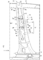
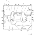
- FIG. 1 It is a perspective view which shows the vehicle body structure of the embodiment which concerns on this invention. It is a perspective view which shows the state which the vehicle body structure of an embodiment is broken by a center pillar. It is a perspective view which shows the center pillar and the roof side rail of the vehicle body structure of an embodiment. It is an exploded perspective view which shows the state which disassembled the outer panel from the vehicle body structure of FIG. It is an exploded perspective view which shows the roof side rail and the roof arch of the vehicle body structure of an embodiment. It is a perspective view which shows the state which was broken along the VI-VI line of FIG. It is a perspective view which shows the state which was broken along the line VII-VII of FIG. It is a side view which looked at the vehicle body structure of an embodiment from the vehicle interior side. It is sectional drawing which was broken along the IX-IX line of FIG. It is sectional drawing which was broken along the X-ray line of FIG.
- the arrow FR indicates the front of the vehicle
- the arrow UP indicates the upper part of the vehicle
- the arrow LH indicates the left side of the vehicle.
- the vehicle body structure 10 of the embodiment has a substantially symmetrical configuration, the left and right constituent members are designated by the same reference numerals, and the configuration on the left side will be mainly described in detail.
- the vehicle body structure 10 includes a side sill 12, a center pillar 14, a roof side rail 16, and a roof arch 18.
- the side sill 12 is formed in a hollow closed cross section extending in the front-rear direction of the vehicle body on the side of the lower portion of the vehicle body.
- the center pillar 14 extends upward from the central portion 12a of the side sill 12 in the front-rear direction of the vehicle body.
- the roof side rail 16 is fixed to the upper end portion 14a of the center pillar 14.
- the roof side rail 16 is formed in a hollow closed cross section (see FIG. 4) extending in the front-rear direction of the vehicle body on the side of the upper portion of the vehicle body.
- a roof arch 18 is joined to the roof side rail 16. The roof arch 18 is bridged over the left and right roof side rails 16.
- the side sill 12 includes a side sill outer panel 21 and a side sill inner panel 22.
- the side sill outer panel 21 is formed in a hat cross section having an upper flange 21a and a lower flange 21b.
- the side sill inner panel 22 is formed in a hat cross section having an upper flange 22a and a lower flange 22b.
- the upper flanges 21a and 22a of the side sill outer panel 21 and the side sill inner panel 22 are joined to each other.
- the lower flanges 21b and 22b of the side sill outer panel 21 and the side sill inner panel 22 are joined to each other.
- the side sill 12 is formed in a hollow closed cross section by the side sill outer panel 21 and the side sill inner panel 22.
- the side sill 12 has a continuous hollow structure formed in the front-rear direction of the vehicle body.
- the side sill 12 is a skeleton member having high strength and rigidity with respect to a load in front and rear of the vehicle body.
- the roof side rail 16 extends in the front-rear direction of the vehicle body on the side above the vehicle body.
- the roof side rail 16 includes a roof side outer panel (outer wall) 25, a roof side inner panel (inner wall) 26, a rail reinforcing member (reinforcing member) 27, and a rail bulkhead 28.
- the roof side outer panel 25 is formed in a U-shaped cross section that opens inward in the vehicle width direction.
- the roof side outer panel 25 has a roof bulging portion 30, an outer upper flange (roof top portion) 31, an outer lower flange (lower flange) 32, and a recess 33.
- the roof bulging portion 30 is bulged toward the outside in the vehicle width direction.
- the roof bulging portion 30 has a first ridge line 35 and a second ridge line 36 at intervals in the vertical direction.
- the first ridge line 35 projects in a V shape toward the outside in the vehicle width direction, and is a continuous ridge line from the front end 16a to the rear end 16b (see FIG. 1) of the roof side rail 16 in a substantially straight line without any bend.
- the strength and rigidity of the first ridge line 35 are ensured so that the load input from the front-rear direction of the vehicle body can be transmitted to the roof side rail 16. As a result, the load input from the front end 16a or the rear end 16b of the roof side rail 16 can be supported by the roof side rail 16.
- the second ridge line 36 is arranged below the first ridge line 35. Like the first ridge line 35, the second ridge line 36 projects in a V shape toward the outside in the vehicle width direction and extends in the vehicle body front-rear direction.
- the second ridge line 36 has a bent portion 38 at a position facing the roof arch connecting portion 45a described later. In other words, the bent portion 38 is provided at a position corresponding to the roof arch connecting portion 45a in the front-rear direction of the vehicle body.
- the bent portion 38 is formed so as to be recessed in a trapezoidal shape toward, for example, the first ridge line 35 side.
- the recess 33 is formed so as to be recessed inward in the vehicle width direction.
- the recess 33 has a bottom portion 41 and a top portion 42.
- the bottom portion 41 is connected to the outer flange lower flange 32.
- the bottom portion 41 is formed flat so as to be flush with the outer flange lower flange 32.
- the top portion 42 projects from the upper end 41a of the bottom portion 41 to the bent portion 38.
- the top portion 42 is formed in a trapezoidal shape along the bent portion 38, for example.
- the upper end portion 14a of the center pillar 14 (specifically, the upper end portion 55b of the outer panel 55, which will be described later) is joined to the bottom portion 41 and the top portion 42 of the recess 33 and the upper portion 43 of the recess 33.
- first ridge line 35 and the second ridge line 36 may be further added to the roof side outer panel 25.
- the outer upper flange 31 projects from the upper side of the roof bulging portion 30 toward the inside in the vehicle width direction.
- the outer lower flange 32 is projected so as to gradually incline outward in the vehicle width direction from the lower side of the roof bulging portion 30 downward.
- the roof side inner panel 26 is formed in an L-shaped cross section so as to be joined to the roof side outer panel 25 from the inside in the vehicle width direction.
- the roof side inner panel 26 has a roof wall portion 45, an inner upper flange 46, and an inner lower flange 47.
- the roof wall portion 45 is arranged so as to close the opening of the roof bulging portion 30 from the inside in the vehicle width direction.
- the roof wall portion 45 has a roof arch connecting portion 45a to which the roof arch 18 described later is connected.
- the inner upper flange 46 projects from the upper side of the roof bulging portion 30 toward the inside in the vehicle width direction along the outer upper flange 31. From the lower side of the roof bulging portion 30, the inner lower flange 47 projects downward along the outer lower flange 32 so as to gradually incline outward in the vehicle width direction.
- the inner upper flange 46 is joined to the outer upper flange 31 from below.
- the inner lower flange 47 is joined to the outer lower flange 32 from the inside in the vehicle width direction.
- the roof side rail 16 is formed in a hollow closed cross section by the roof side outer panel 25 and the roof side inner panel 26.
- the roof side rail 16 is a highly rigid member that forms a vehicle body skeleton on the side of the upper portion of the vehicle body.
- the roof panel 48 is joined to the outer upper flange of the roof side rail 16 from above.
- the roof side outer panel 25 is formed in a U-shaped cross section that opens inward in the vehicle width direction.
- the roof side outer panel 25 is formed with an outer upper flange 31 projecting inward in the vehicle width direction.
- the inner upper flange 46 of the roof side inner panel 26 projects inward in the vehicle width direction along the outer upper flange 31. Therefore, the outer upper flange 31 and the inner upper flange 46 can be arranged below the roof side rail 16 in the vertical direction so as to be close to the hollow closed cross section.
- the roof panel 48 is joined to the outer upper flange 31 from above. As a result, the height of the vehicle interior space can be suitably secured in a state where the vertical position (that is, the vehicle height) of the roof panel 48 is lowered.
- the rail reinforcing member 27 is joined to the inner surface of the roof side outer panel 25.
- the rail reinforcing member 27 is a member formed along the inner surface of the roof bulging portion 30 to reinforce the roof side outer panel 25.
- the rail reinforcing member 27 is joined to the inner surface of the roof bulging portion 30 at a position facing the roof arch connecting portion 45a of the roof side inner panel 26 in the front-rear direction of the vehicle body.
- the rail reinforcing member 27 is arranged at a position facing the rail bulkhead 28, which will be described later.
- a rail bulkhead 28 is provided on the hollow closed cross section of the roof side rail 16.
- the rail bulkhead 28 has a cross-section shielding portion 51 and a joint piece 52.
- the rail bulkhead 28 is formed in a U-shaped cross section by the cross-section shielding portion 51 and the joint piece 52.
- the cross-section shielding portion 51 is arranged in the vehicle width direction so as to be aligned with, for example, the outer front side wall 65 (see FIG. 3) of the center pillar 14 described later and the arch front side wall 122 of the roof arch 18 described later in the vehicle body front-rear direction. It is placed facing you.
- the cross-section shielding portion 51 is aligned in the vehicle width direction with, for example, the outer rear side wall 66 of the center pillar (see FIG. 3) described later and the arch rear side wall 123 of the roof arch 18 described later. It is placed facing.
- the outer front side wall 65 (side wall) and the outer rear side wall 66 (side wall) are a pair of side walls, one of the pair of side walls is the outer front side wall 65, and the other of the pair of side walls is the outer rear side wall 66.
- the arch front side wall 122 and the arch rear side wall 123 are a pair of side walls, one of the pair of side walls is the arch front side wall 122, and the other of the pair of side walls is the arch rear side wall 123.
- a joint piece 52 projects from the periphery of the cross-section shielding portion 51 along the inner surface of the roof bulging portion 30 and the inner surface of the roof wall portion 45.
- the joint piece 52 is joined to the inner surface selected from the roof bulging portion 30, the roof wall portion 45, and the rail reinforcing member 27.
- the rail bulkhead 28 is joined to the roof side outer panel 25 or the roof side inner panel 26.
- the cross-section shielding portion 51 may be aligned with either the outer front side wall 65 of the center pillar 14 or the arch front side wall 122 of the roof arch 18 in the front-rear direction of the vehicle body. Alternatively, the cross-section shielding portion 51 may be aligned with either the outer rear side wall 66 of the center pillar 14 or the arch rear side wall 123 of the roof arch 18 in the front-rear direction of the vehicle body.
- the rail bulkhead 28 is not limited to the U-shaped cross section, but may be formed in a hat cross section or a crank cross section. As described above, the rail bulkhead 28 is formed in, for example, a U-shaped cross section, a hat cross section, or a crank cross section. Thereby, the rail bulkhead 28 can be easily manufactured, and further, the rail bulkhead 28 can be easily joined to the roof side rail 16.
- the center pillar 14 is joined to the side sill 12 and the roof side rail 16.
- the lower end portion 14b of the center pillar 14 is joined to the side sill 12.
- the upper end portion 14a of the center pillar 14 is joined to the roof side rail 16.
- the center pillar 14 includes an outer panel 55, an inner panel 56, a stiffener 57, and a pillar bulkhead 58.
- the center pillar 14 has a hollow closed cross section formed by joining the outer panel 55 and the inner panel 56, and the formed hollow closed cross section extends in the vertical direction.
- the center pillar 14 is curved inward between the roof side rail 16 and the belt line portion 78, which will be described later.
- the outer panel 55 includes an outer bulging portion 61, an outer front brim portion 62, and an outer rear brim portion 63.
- the outer bulging portion 61 bulges outward in the vehicle width direction.
- the outer front brim portion 62 projects forward from the outer bulging portion 61 to the front of the vehicle body.
- the outer rear brim portion 63 projects rearward from the outer bulging portion 61 to the rear of the vehicle body.
- the outer bulging portion 61 has an outer top portion (top) 64, an outer front side wall 65, and an outer rear side wall 66.
- the outer top portion 64 is arranged so as to face the front-rear direction of the vehicle body.
- the outer front side wall 65 extends inward in the vehicle width direction from the front side of the outer top 64.
- the outer rear side wall 66 extends inward in the vehicle width direction from the rear side of the outer top 64.
- the outer bulging portion 61 is formed in a U-shaped cross section opened inward in the vehicle width direction by the outer top portion 64, the outer front side wall 65, and the outer rear side wall 66.
- the outer front brim portion 62 projects from the front opening side of the outer bulging portion 61 (that is, the outer front side wall 65) toward the front of the vehicle body.
- the outer rear brim portion 63 projects from the rear opening side of the outer bulging portion 61 (that is, the outer rear side wall 66) toward the rear of the vehicle body.
- the outer panel 55 is formed in a hat cross section that opens inward in the vehicle width direction by the outer bulging portion 61, the outer front brim portion 62, and the outer rear brim portion 63.
- the lower end portion 55a of the outer panel 55 is joined to the outer surface 21c of the side sill outer panel 21.
- the upper end portion 55b of the outer panel 55 is joined to the recess 33 (specifically, the bottom portion 41 and the top portion 42) and the upper portion 43 of the recess 33 on the outer surface 25a of the roof side outer panel 25.
- the upper end portion 55b of the outer panel 55 has, for example, a portion 61a that bulges upward.
- the bulging portion 61a forms the upper end portion of the outer bulging portion 61.
- the bulging portion 61a is formed so as to surround the upper end portion 71a (described later) of the first stiffener (stiffener) 71 arranged in the recess 33 from above.
- the stiffener 57 is arranged inside the outer bulging portion 61.
- the stiffener 57 includes a first stiffener 71 and a second stiffener 72.
- the first stiffener 71 is joined so as to be overlapped on the inner surface of the outer bulging portion 61.
- the first stiffener 71 is formed in a U-shaped cross section along the outer top portion 64, the outer front side wall 65, and the outer rear side wall 66 of the outer bulging portion 61.
- the first stiffener 71 has a first top portion 74, a first front vertical wall (vertical wall) 75, and a first rear vertical wall (vertical wall) 76.
- the first top 74 is along the outer top 64.
- the first front vertical wall 75 is along the outer front side wall 65.
- the first rear vertical wall (vertical wall) 76 is along the outer rear side wall 66.
- the first stiffener 71 extends in the vertical direction so as to intersect the belt line portion (belt line) 78.
- the belt line portion 78 refers to a line running laterally along the lower end portion of the side window glass of the vehicle body.
- the first stiffener 71 has an upper end portion 71a arranged at the bottom portion 41 of the recess 33 and joined. Specifically, in the first stiffener 71, the upper end portion 71a (the upper end portion 75a of the first front vertical wall 75 and the upper end portion 76a of the first rear vertical wall 76) is arranged and joined to the bottom portion 41 of the recess 33. ing.
- the first front vertical wall 75 extends from the outer panel 55 to the inner panel 56 of the center pillar 14 between the roof side rail 16 (specifically, the upper end portion 75a of the first front vertical wall 75) and the belt line portion 78. It overhangs inward in the width direction of the vehicle.
- the first rear vertical wall 76 extends from the outer panel 55 of the center pillar 14 to the inner panel 56 between the roof side rail 16 (specifically, the upper end portion 76a of the first rear vertical wall 76) and the belt line portion 78. It overhangs inward in the width direction of the vehicle.
- the second stiffener 72 is joined in a state of being overlapped on the inner surface of the first stiffener 71.
- the second stiffener 72 has a second top 81, a second front vertical wall 82, and a second rear vertical wall 83.
- the second top 81, the second front vertical wall 82, and the second rear vertical wall 83 form a second stiffener 72 in a U-shaped cross section along the inner surface of the first stiffener 71.
- the second stiffener 72 is formed to have a smaller height dimension in the vertical direction than the first stiffener 71, and extends upward from, for example, the belt line portion 78 to the belt line upper position 79.
- the maximum plate thickness portion 73 of the stiffener 57 is formed between the belt line portion 78 and the roof side rail 16.
- the stiffener 57 has a maximum plate thickness portion 73 between the belt line portion 78 and the roof side rail 16.
- the maximum plate thickness portion 73 may be formed by increasing the plate thickness of one stiffener. In the center pillar 14, a portion curved inward between the roof side rail 16 and the belt line portion 78 is reinforced with a stiffener 57 against a load in the vehicle width direction.
- the inner panel 56 includes an inner bulging portion 85, an inner front brim portion 86, and an inner rear brim portion 87.
- the inner bulging portion 85 bulges inward in the vehicle width direction.
- the inner front brim portion 86 projects from the inner bulging portion 85 to the front of the vehicle body.
- the inner rear brim portion 87 projects from the inner bulging portion 85 to the rear of the vehicle body.
- the inner bulging portion 85 has an inner top portion 91, an inner front wall 92, and an inner rear wall 93.
- the inner top 91 is arranged so as to face the front-rear direction of the vehicle body.
- the inner front wall 92 extends outward in the vehicle width direction from the front side of the inner top 91.
- the inner rear wall 93 extends inward in the vehicle width direction from the rear side of the inner top 91.
- the inner top 91, the inner front wall 92, and the inner rear wall 93 form the inner bulging portion 85 in a U-shaped cross section that is opened outward in the vehicle width direction.
- the inner front brim portion 86 projects from the front opening side of the inner bulging portion 85 (that is, the inner front wall 92) toward the front of the vehicle body.
- the inner rear brim portion 87 projects from the rear opening side of the inner bulging portion 85 (that is, the inner rear wall 93) toward the rear of the vehicle body.
- the inner panel 56 is formed in a hat cross section (second hat cross section) that opens outward in the vehicle width direction by the inner bulging portion 85, the inner front brim portion 86, and the inner rear brim portion 87.
- the inner front brim portion 86 is joined to the outer front brim portion 62 of the outer panel 55.
- the inner rear brim portion 87 is joined to the outer rear brim portion 63 of the outer panel 55.
- the inner panel 56 is joined to the outer panel 55, and the center pillar 14 is formed in a hollow closed cross section by the inner panel 56 and the outer panel 55.
- the center pillar 14 is a highly rigid member that extends in the vertical direction between the side sill 12 and the roof side rail 16 to form a vehicle body skeleton.
- the lower end portion 56a is joined by penetrating the side sill 12 in the vertical direction. That is, the lower end portion 56a of the inner panel 56 is joined in a state of being sandwiched between the upper flange 21a of the side sill outer panel 21 and the upper flange 22a of the side sill inner panel 22. Further, the lower end portion 56a of the inner panel 56 is joined to the lower flange 21b of the side sill outer panel 21 and the lower flange 22b of the side sill inner panel 22 in a sandwiched state. The lower end portion 55a of the outer panel 55 is joined to the outer surface 21c of the side sill outer panel 21. As a result, the lower end portion 14b of the center pillar 14 is firmly joined to the side sill 12.
- the upper end portion 56b of the inner panel 56 is joined to the inner surface (the surface on the vehicle interior side) 26a of the roof side inner panel 26.
- the upper end portion 55b of the outer panel 55 is joined to the recess 33 (specifically, the bottom portion 41 and the top portion 42) and the upper portion 43 of the recess 33 on the outer surface 25a of the roof side outer panel 25.
- the upper end portion 71a of the first stiffener 71 that is, the upper end portion 75a of the first front vertical wall 75 and the upper end portion 76a of the first rear vertical wall 76
- the upper end portion 14a of the center pillar 14 is firmly joined to the roof side rail 16.
- the center pillar 14 includes a pillar bulkhead 58 above the belt line portion 78.
- the pillar bulkhead 58 includes a first pillar bulkhead (pillar bulkhead) 96 and a second pillar bulkhead (pillar bulkhead) 97.
- the first pillar bulkhead 96 is provided inside the first stiffener 71 above the belt line portion 78.
- the first pillar bulkhead 96 has a first partition wall (partition wall) 101, a first folded flange 102, and a second folded flange 103.
- the first partition wall 101 is arranged horizontally so as to intersect the longitudinal direction of the first stiffener 71.
- the first partition wall 101 has a first outer side 101a, a first front side 101b, a first rear side 101c, and a first inner side 101d.
- the first outer side 101a, the first front side 101b, and the first rear side 101c form the outline of the outer shape of the first partition wall 101 along the U-shaped cross section of the first stiffener 71.
- the first inner side 101d is arranged on the opening side (inner bulging portion 85 side) of the first stiffener 71.
- a first folding flange 102 is provided on the first outer side 101a, the first front side 101b, and the first rear side 101c, respectively. Specifically, of the first outer side 101a, the first folding flange 102 is bent downward from the central portion in the front-rear direction of the vehicle body along the first top 74 of the first stiffener 71, and the first top is formed. It is joined to 74. From the first front side 101b, the first folding flange 102 is bent downward along the first front vertical wall 75 of the first stiffener 71 and joined to the first front vertical wall 75.
- the first folding flange 102 is bent downward along the first rear vertical wall 76 of the first stiffener 71 and is joined to the first rear leg portion 67. That is, the first partition wall 101 is joined to the inside of the U-shaped cross section of the first stiffener 71 by the first folding flange 102.
- a second folded flange 103 is provided on the first inner side 101d. Specifically, of the first inner side 101d, the second folded flange 103 is bent upward along the inner bulging portion 85 of the inner panel 56 from the central portion in the front-rear direction of the vehicle body, and the inner bulging portion is formed. It is connected to 85 by a fastening member (for example, bolt 105, nut).
- a fastening member for example, bolt 105, nut
- the first folded flange 102 is joined to the first top portion 74, the first front vertical wall 75, and the first rear vertical wall 76 of the first stiffener 71 in a U-shaped cross section.
- the second folded flange 103 is coupled to the inner bulging portion 85.
- a second pillar bulkhead 97 is provided inside the second stiffener 72 of the center pillar 14.
- the second pillar bulkhead 97 is formed substantially symmetrically with the first pillar bulkhead 96 in the vertical direction.
- the second pillar bulkhead 97 is provided inside the second stiffener 72 above the belt line portion 78.
- the second partition wall (partition wall) 111 of the second pillar bulkhead 97 is joined to the inside of the U-shaped cross section of the second stiffener 72 by the first folding flange 112.
- the second partition wall 111 is arranged horizontally so as to intersect the longitudinal direction of the second stiffener 72.
- the second folded flange 113 of the second partition wall 111 is connected to the inner bulging portion 85 of the inner panel 56 by a fastening member (for example, bolt 115, nut). Therefore, the second partition wall 111 is connected to the inner bulging portion 85 by the second folded flange 113.
- a fastening member for example, bolt 115, nut.
- a first pillar bulkhead 96 is provided on the first stiffener 71.
- a second pillar bulkhead 97 is provided on the second stiffener 72. Therefore, the outer front side wall 65 and the outer rear side wall 66 of the center pillar 14 (outer panel 55) are reinforced by the first pillar bulkhead 96 and the second pillar bulkhead 97.
- the outer front side wall 65 and the outer rear side wall 66 are reinforced by the first pillar bulkhead 96 and the second pillar bulkhead 97.
- the roof arch 18 is joined to the roof arch connecting portion 45a of the roof side rail 16 (specifically, the roof side inner panel 26).
- the roof arch 18 includes an arch bulging portion 117, an arch front brim portion 118, and an arch rear brim portion 119.
- the arch bulging portion 117 bulges downward.
- the arch front brim portion 118 projects from the arch bulging portion 117 to the front of the vehicle body.
- the arch rear brim portion 119 projects rearward from the arch bulging portion 117.
- the arch bulging portion 117 has an arch top portion 121, an arch front side wall 122, and an arch rear side wall 123.
- the arch top 121 is arranged substantially horizontally.
- the arch front side wall 122 extends upward from the front side of the arch top 121.
- the arch rear side wall 123 extends upward from the rear side of the arch top 121.
- the arch top 121, the arch front side wall 122, and the arch rear side wall 123 form the arch bulge 117 in a U-shaped cross section that is open upward.
- the arch front brim 118 projects from the front opening side of the arch bulge 117 (that is, the arch front side wall 122) toward the front of the vehicle body.
- the arch rear brim portion 119 projects from the rear opening side of the arch bulging portion 117 (that is, the arch rear side wall 123) toward the rear of the vehicle body.
- the roof arch 18 is formed in a hat cross section (first hat cross section) that opens upward by the arch bulging portion 117, the arch front brim portion 118, and the arch rear brim portion 119.
- the arch end portion (end portion) 18a is bent downward along the roof arch connecting portion 45a in front of the roof side rail 16 (specifically, the roof arch connecting portion 45a).
- the upper end portion 56b of the inner panel 56 is formed in the second hat cross section.
- the upper end portion 56b of the inner panel 56 may be referred to as an “inner upper end portion 56b”.
- the first hat cross section of the arch end portion 18a is joined to the second hat cross section of the inner upper end portion 56b in a state of being overlapped from the inside in the vehicle width direction.
- the axis G1 of the roof arch 18 is formed so as to intersect the axis G3 of the center pillar 14 at the cross-sectional center G2 of the roof side rail 16.
- the first ridge line 35 of the roof side outer panel 25 is provided from the front end 16a to the rear end 16b of the roof side rail 16. It was made continuous. As a result, the collision load (load) due to the front collision or the rear collision can be transmitted by the first ridge line 35, and the collision load can be supported by the roof side rail 16.
- a bent portion 38 was formed at a position of the second ridge line 36 corresponding to the roof arch connecting portion 45a, and a recess 33 was formed in the roof side outer panel 25.
- the upper end portion 14a of the center pillar 14 was joined to the bottom portion 41 of the recess 33.
- the first stiffener 71 is joined by arranging the upper end portion 71a (the upper end portion 75a of the first front vertical wall 75 and the upper end portion 76a of the first rear vertical wall 76) at the bottom portion 41 of the recess 33. Therefore, the upper end portion 14a of the center pillar 14 can be arranged at a position close to the roof arch 18 in the vertical direction. Therefore, when the collision load F1 is input to the center pillar 14 due to a side collision, the load F2 can be efficiently transmitted from the upper end portion 14a of the center pillar 14 to the roof arch 18. As a result, when the collision load F1 is input to the center pillar 14, the transmission loss (transmission loss) of the collision load from the center pillar 14 to the roof arch 18 can be reduced.
- the axis G1 of the roof arch 18 is arranged at a position intersecting the axis G3 of the center pillar 14 at the cross-sectional center 2 of the roof side rail 16.
- a bending moment M1 about the cross-sectional center G2 of the roof side rail 16 acts on the upper end portion 14a of the center pillar 14. Therefore, at the cross-sectional center G2 of the roof side rail 16, the axis G1 of the roof arch 18 and the axis G3 of the center pillar 14 are crossed. Therefore, the bending moment M1 centered on the cross-sectional center G2 of the roof side rail 16 can be suppressed by the roof arch 18.
- the collision load F2 can be efficiently transmitted from the upper end portion 14a of the center pillar 14 to the roof arch 18.
- the arch end portion 18a of the roof arch 18 is formed in the first hat cross section.
- the first hat cross section of the arch end portion 18a is joined to the second hat cross section of the inner upper end portion 56b of the inner panel 56 in a state of being overlapped from the inside in the vehicle width direction. Therefore, when the side impact load F1 is input to the inner panel 56 of the center pillar 14, the collision load F2 can be efficiently transmitted from the inner panel 56 to the roof arch 18. Therefore, the depth of the hat cross section of the outer panel 55 can be made shallow while the load transmission from the center pillar 14 to the roof arch 18 is ensured.
- the door window frame of the vehicle can be set thin and the surface of the vehicle can be made into a flash surface.
- the flash surface refers to a surface structure that eliminates steps as much as possible from the surface of the vehicle in order to reduce the air resistance of the vehicle.
- a rail bulkhead 28 is provided inside the hollow closed cross section of the roof side rail 16.
- the cross-section shielding portion 51 of the rail bulkhead 28 is arranged on the outer front side wall 65 of the center pillar 14 and the arch front side wall 122 of the roof arch 18 so as to be aligned in the vehicle body width direction. ..
- the cross-section shielding portion 51 is arranged on the outer rear side wall 66 of the center pillar 14 and the arch rear side wall 123 of the roof arch 18 so as to be aligned in the front-rear direction of the vehicle body so as to face the vehicle width direction.
- the roof side rail 16 is provided with a rail reinforcing member 27, and the rail reinforcing member 27 is opposed to the rail bulkhead 28. Therefore, when the side impact load F1 is input to the inner panel 56 of the center pillar 14, the collision load F2 is satisfactorily received by the rail reinforcing member 27, and the received collision load F2 is transmitted from the rail reinforcing member 27 to the rail bulkhead 28. be able to. As a result, the collision load F2 can be satisfactorily transmitted to the roof arch 18 via the rail reinforcing member 27 and the rail bulkhead 28.
- the upper end portion 71a (the upper end portion 75a of the first front vertical wall 75 and the upper end portion 76a of the first rear vertical wall 76) is arranged and joined to the bottom portion 41 of the recess 33. Further, the first front vertical wall 75 of the first stiffener 71 is inserted from the outer panel 55 of the center pillar 14 between the roof side rail 16 (the upper end portion 75a of the first front vertical wall 75) and the belt line portion 78. It overhangs to the panel 56 inward in the vehicle width direction.
- first rear vertical wall 76 of the first stiffener 71 is located between the roof side rail 16 (the upper end portion 76a of the first rear vertical wall 76) and the belt line portion 78 from the outer panel 55 of the center pillar 14. It projects inward in the vehicle width direction up to the inner panel 56.
- the center pillar 14 that curves inward between the roof side rail 16 and the belt line portion 78 can be reinforced with the stiffener 57 against the lateral impact load F1 in the vehicle width direction.
- a negative bending moment M1 acts on the center pillar 14 near the roof side rail 16 which is the upper fulcrum of the side collision
- the cross section of the center pillar 14 is deformed so as to be crushed in the vehicle width direction. It can be suppressed with Stifuna 57. Therefore, the collision load F2 can be efficiently transmitted from the inner panel 56 to the roof arch 18.
- the first stiffener 71 is formed in a U-shaped cross section along the outer top portion 64, the outer front side wall 65, and the outer rear side wall 66 of the outer bulging portion 61.
- the first stiffener 71 extends in the vertical direction so as to intersect the belt line portion 78. Therefore, in the center pillar 14, the strength and rigidity in the range where the colliding object interferes due to the side collision can be increased by the stiffener 57. That is, the collision load F1 input to the center pillar 14 due to the side collision can be satisfactorily distributed as the collision load F2 on the upper roof side rail 16 and as the collision load F3 on the lower side sill 12. As a result, the collision load F1 input to the center pillar 14 due to the side collision can be supported by the roof side rail 16 and the side sill 12.
- the maximum plate thickness portion 73 of the stiffener 57 is formed between the belt line portion 78 and the roof side rail 16. Therefore, it is possible to increase the strength and rigidity of the portion where the maximum bending moment is generated at the time of a side collision. As a result, the collision load F1 input by the side collision can be satisfactorily distributed as the collision load F2 on the upper roof side rail 16 and as the collision load F3 on the lower side sill 12.
- first pillar bulkhead 96 and the second pillar bulkhead 97 are provided above the belt line portion 78.
- the first partition wall 101 of the first pillar bulkhead 96 is arranged horizontally so as to intersect the longitudinal direction of the first stiffener 71.
- the second partition wall 111 of the second pillar bulkhead 97 is arranged horizontally so as to intersect the longitudinal direction of the second stiffener 72. Therefore, in the center pillar 14, the range above the belt line portion 78 can be reinforced by the first pillar bulkhead 96 and the second pillar bulkhead 97 with respect to the load in the vehicle body front-rear direction.
- the collision load F1 input by the side collision can be satisfactorily distributed as the collision load F2 on the upper roof side rail 16 and as the collision load F3 on the lower side sill 12.
- the upper end 55b of the outer panel 55 is joined to the bottom 41 and the top 42 of the recess 33 and the upper portion 43 of the recess 33 on the outer surface 25a of the roof side outer panel 25. Therefore, the upper end portion 14a of the center pillar 14 is firmly joined to the roof side rail 16. As a result, when the side impact load F1 is input to the center pillar 14, the collision load F2 can be efficiently transmitted to the roof arch 18 via the roof side rail 16.
Landscapes
- Engineering & Computer Science (AREA)
- Chemical & Material Sciences (AREA)
- Combustion & Propulsion (AREA)
- Transportation (AREA)
- Mechanical Engineering (AREA)
- Body Structure For Vehicles (AREA)
Abstract
車体構造(10)は、ルーフサイドレール(16)のルーフサイドインナパネル(26)に、第1の稜線(35)と、第2の稜線(36)と、凹部(33)と、を形成した。第1の稜線は、ルーフサイドレールに車体前後方向から入力する荷重を伝達可能に、ルーフサイドレールの前端から後端まで連続して延びている。第2の稜線は、ルーフアーチ連結部に車体前後方向で一致する位置において、凹部を形成するように第1の稜線側に凹む折曲部(38)を有する。凹部にセンタピラー(14)の上端部が接合されている。
Description
本発明は、車体構造に関する。
本願は、2019年10月4日に出願された日本国特願2019-183601号に基づき優先権を主張し、その内容をここに援用する。
本願は、2019年10月4日に出願された日本国特願2019-183601号に基づき優先権を主張し、その内容をここに援用する。
車体構造は、ルーフサイドレールが車体上部の側方において車体前後方向に延設され、サイドシルが車体下部の側方において車体前後方向に延設され、サイドシルおよびルーフサイドレールにセンタピラーが接合されている(例えば、特許文献1参照)。
側面衝突によりセンタピラーに衝突荷重が入力した際に、入力した衝突荷重がセンタピラーの下端部を経てサイドシルに伝達され、センタピラーの上端部を経てルーフサイドレールに伝達される。
ルーフサイドレールにはルーフアーチが接合され、ルーフアーチが車幅方向に延びている。よって、ルーフサイドレールに伝達された衝突荷重は、ルーフサイドレールを経てルーフアーチに伝達される。
側面衝突によりセンタピラーに衝突荷重が入力した際に、入力した衝突荷重がセンタピラーの下端部を経てサイドシルに伝達され、センタピラーの上端部を経てルーフサイドレールに伝達される。
ルーフサイドレールにはルーフアーチが接合され、ルーフアーチが車幅方向に延びている。よって、ルーフサイドレールに伝達された衝突荷重は、ルーフサイドレールを経てルーフアーチに伝達される。
ここで、センタピラーはベルトラインより上方では室内側に湾曲するとともに、前後の窓ガラスを広くするため細幅化されている。側面衝突によりセンタピラーに入力した衝突荷重を、ルーフサイドレールを経てルーフアーチに伝達することにより、ルーフアーチで衝突荷重を支えるが、センタピラーに入力した衝突荷重を、ルーフサイドレールを経てルーフアーチに効率よく伝達させる技術の実用化が望まれている。
本発明の態様は、側面衝突によりセンタピラーに入力する衝突荷重をルーフアーチに効率よく伝達できる車体構造を提供する。
(1)本発明に係る車体構造は、車体上方の側方で車体前後方向に延設され、内壁および外壁により中空閉断面が形成されたルーフサイドレールと、前記内壁のルーフアーチ連結部に接合されたルーフアーチと、前記ルーフサイドレールに上端部が接合され、下端部がサイドシルに接合されたセンタピラーと、を備えている車体構造において、前記外壁は、上下に設けられた第1の稜線および第2の稜線と、前記第2の稜線に設けられた凹部と、を有し、前記第1の稜線は、前記ルーフサイドレールに車体前後方向から入力する荷重を伝達可能に、前記ルーフサイドレールの前端から後端まで連続して延び、前記第2の稜線は、前記ルーフアーチ連結部に車体前後方向で一致する位置において、前記凹部を形成するように第1の稜線の側に凹む折曲部を有し、前記凹部に前記センタピラーの上端部が接合されている。
(1)の態様によれば、ルーフサイドレールに車体前後方向から入力する荷重を伝達可能に、第1の稜線をルーフサイドレールの前端から後端まで折曲部なく連続して延ばした。これにより、前面衝突や後面衝突による衝突荷重(荷重)を第1の稜線で伝達させて、衝突荷重をルーフサイドレールで支えることができる。
そして、第2の稜線のうち、ルーフアーチ連結部に一致する位置に折曲部を形成して、外壁に凹部を形成した。この凹部にセンタピラーの上端部を接合した。よって、センタピラーの上端部をルーフアーチに近い位置に配置できる。これにより、側面衝突によりセンタピラーに入力した衝突荷重を、センタピラーの上端部からルーフアーチに効率よく伝達でき、ルーフアーチへの伝達損失(伝達ロス)を減少できる。
そして、第2の稜線のうち、ルーフアーチ連結部に一致する位置に折曲部を形成して、外壁に凹部を形成した。この凹部にセンタピラーの上端部を接合した。よって、センタピラーの上端部をルーフアーチに近い位置に配置できる。これにより、側面衝突によりセンタピラーに入力した衝突荷重を、センタピラーの上端部からルーフアーチに効率よく伝達でき、ルーフアーチへの伝達損失(伝達ロス)を減少できる。
(2)上記(1)の態様において、前記ルーフサイドレールの断面中心において、前記ルーフアーチの軸心と、前記センタピラーの軸心と、が交差していてもよい。
ここで、側面衝突による側突荷重がセンタピラーに入力した場合、センタピラーの上端部にルーフサイドレールの断面中心を軸とする曲げモーメントが作用する。そこで、(2)の態様において、ルーフサイドレールの断面中心において、ルーフアーチの軸心とセンタピラーの軸心とを交差させた。よって、ルーフサイドレールの断面中心を軸とする曲げモーメントをルーフアーチで抑制できる。これにより、側面衝突によりセンタピラーに入力した衝突荷重を、センタピラーの上端部からルーフアーチに効率よく伝達できる。
(3)上記(1)または(2)の態様において、前記ルーフアーチは、上方へ向けて開口する第1のハット断面に形成され、前記ルーフサイドレールの内壁の手前で端部が下方に折れ曲げられてもよく、前記センタピラーは、前記端部の第1のハット断面に沿って重ねられるように第2のハット断面に形成されたインナパネルを有していてもよい。
(3)の態様によれば、センタピラーのインナパネルを第2のハット断面に形成した。この第2のハット断面をルーフアーチの第1のハット断面に沿って重ねるようにした。よって、センタピラーのインナパネルに入力した側突荷重をルーフアーチに効率よく伝達できる。
このため、センタピラーからルーフアーチへの荷重伝達を確保した状態において、ハット断面に形成されたアウタパネルの深さを浅くできる。これにより、車両のドア窓枠を細く設定して、車両の表面をフラッシュサーフェスにできる。
フラッシュサーフェスとは、車両の空気抵抗を減らすために、車両の表面から極力段差をなくする表面構造をいう。
このため、センタピラーからルーフアーチへの荷重伝達を確保した状態において、ハット断面に形成されたアウタパネルの深さを浅くできる。これにより、車両のドア窓枠を細く設定して、車両の表面をフラッシュサーフェスにできる。
フラッシュサーフェスとは、車両の空気抵抗を減らすために、車両の表面から極力段差をなくする表面構造をいう。
(4)上記(1)から(3)のいずれかの態様において、前記センタピラーは、内部に配置されて、車幅方向に延びる縦壁を有するスチフナを備えてもよく、前記スチフナは、前記縦壁の上端部が前記凹部に配置され、前記ルーフサイドレールとベルトラインとの間において、前記縦壁が前記センタピラーのアウタパネルからインナパネルまで張り出されていてもよい。
(4)の態様によれば、スチフナの縦壁の上端部を凹部に配置した。さらに、スチフナの縦壁を、ルーフサイドレールとベルトラインとの間においてアウタパネルからインナパネルまで張り出した。よって、ルーフサイドレールとベルトラインとの間の室内側に湾曲するセンタピラーを、車幅方向の荷重に対してスチフナで補強できる。
これにより、側面衝突の上支点であるルーフサイドレール近傍のセンタピラーに、例えばマイナスの曲げモーメントが作用した場合に、センタピラーの断面が車幅方向に潰れるように変形することをスチフナで抑制できる。
これにより、側面衝突の上支点であるルーフサイドレール近傍のセンタピラーに、例えばマイナスの曲げモーメントが作用した場合に、センタピラーの断面が車幅方向に潰れるように変形することをスチフナで抑制できる。
(5)上記(4)の態様において、前記センタピラーは、前記ベルトラインより上方において、水平に配置された仕切り壁を有するピラーバルクヘッドを備えていてもよい。
(5)の態様によれば、ベルトラインより上方のセンタピラーに、ピラーバルクヘッドの仕切り壁を水平に配置した。よって、ベルトラインより上方の範囲のセンタピラーを、車体前後方向の荷重に対してピラーバルクヘッドで補強できる。
これにより、側面衝突により、衝突物が干渉するベルトラインより上方の範囲のセンタピラーに、例えばプラスの曲げモーメントが作用した場合に、センタピラーの断面が車体前後方向に潰れるように変形することをピラーバルクヘッドで抑制できる。
これにより、側面衝突により、衝突物が干渉するベルトラインより上方の範囲のセンタピラーに、例えばプラスの曲げモーメントが作用した場合に、センタピラーの断面が車体前後方向に潰れるように変形することをピラーバルクヘッドで抑制できる。
(6)上記(4)または(5)の態様において、前記スチフナは、前記センタピラーのアウタパネルのうち、頂部、一対の側壁に沿ってU字断面に形成され、前記ベルトラインに交差するように上下方向に延びていてもよい。
(6)の態様によれば、センタピラーのアウタパネルのうち、頂部、一対の側壁に沿ってスチフナをU字断面に形成する。さらに、スチフナをベルトラインに交差するように上下方向に延ばした。よって、側面衝突により、衝突物が干渉するセンタピラーの範囲の強度、剛性をスチフナで高めることができる。すなわち、側面衝突によりセンタピラーに入力した衝突荷重を上方のルーフサイドレールと、下方のサイドシルとに分散できる。これにより、側面衝突によりセンタピラーに入力した衝突荷重を、ルーフサイドレールとサイドシルとにより支えることができる。
(7)上記(4)から(6)のいずれかの態様において、前記スチフナは、前記ベルトラインと前記ルーフサイドレールとの間に最大板厚部を有していてもよい。
(7)の態様によれば、スチフナのうち、ベルトラインとルーフサイドレールとの間を最大板厚部とした。よって、側面衝突の際に最大曲げモーメントが発生する部位の強度、剛性を高めることができる。これにより、側面衝突により入力する衝突荷重を、上側のルーフサイドレールと、下側のサイドシルに良好に荷重分散できる。
(8)上記(4)から(6)のいずれかの態様において、前記凹部は、前記ルーフサイドレールの下フランジに連結された底部と、前記底部から前記折曲部まで張り出された天部と、を有していてもよく、前記センタピラーのアウタパネルは、前記凹部に配置された前記スチフナの上端部を囲み、前記底部および前記天部に接合する上端部を有していてもよい。
(8)の態様によれば、アウタパネルの上端部でスチフナの上端部を囲み、スチフナの上端部を囲んだ上端部を凹部の底部および天部に接合させた。よって、センタピラーの上端部をルーフサイドレールに強固に接合できる。これにより、センタピラーに入力した衝突荷重を、ルーフサイドレールを経てルーフアーチに良好に伝達できる。
(9)上記(1)から(8)のいずれかの態様において、前記ルーフサイドレールは、前記ルーフアーチおよび前記センタピラーの少なくとも一方の側壁に、車体前後方向において整列する断面遮蔽部を有し、前記外壁または前記内壁に接合されたレールバルクヘッドを備えていてもよい。
(9)の態様によれば、ルーフサイドレールにレールバルクヘッドを備えた。レールバルクヘッドの断面遮蔽部を、ルーフアーチおよびセンタピラーの少なくとも一方の側壁に車体前後方向において整列させた。これにより、センタピラーに入力した衝突荷重を、レールバルクヘッドを経てルーフアーチに良好に伝達できる。
(10)上記(9)の態様において、前記レールバルクヘッドは、ハット断面、クランク断面、U字断面のいずれかに形成されていてもよい。
(10)の態様によれば、レールバルクヘッドをハット断面、クランク断面、U字断面のいずれかに形成した。これにより、レールバルクヘッドを容易に製造でき、さらに、レールバルクヘッドをルーフサイドレールに容易に接合できる。
(11)上記(1)から(10)のいずれかの態様において、前記ルーフサイドレールは、車幅方向内側に向けて開口するU字断面に形成され、ルーフパネルが接合されるルーフ天部を有する前記外壁と、前記外壁に車幅方向内側から接合可能にL字断面に形成されている前記内壁と、を備えていてもよい。
(11)の態様によれば、ルーフサイドレールの外壁を、車幅方向内側に向けて開口するU字断面に形成し、外壁にルーフ天部を形成した。ルーフサイドレールの内壁を、外壁に接合可能にL字断面に形成した。よって、ルーフ天部を上下方向においてルーフサイドレールの閉断面に近づけることができる。これにより、ルーフパネルの上下位置(すなわち、車高)を下げた状態において車室空間の高さを好適に確保できる。
(12)上記(9)または(10)の態様において、前記ルーフサイドレールは、前記レールバルクヘッドに対向する補強部材を備えていてもよい。
(12)の態様によれば、ルーフサイドレールに補強部材を備え、補強部材をレールバルクヘッドに対向させた。よって、センタピラーに入力した衝突荷重を補強部材で良好に受け、受けた衝突荷重を補強部材からレールバルクヘッドに伝えることができる。これにより、センタピラーに入力した衝突荷重をルーフアーチに良好に伝達できる。
本発明の態様によれば、第2の稜線に折曲部を形成して外壁に凹部を形成した。この凹部にセンタピラーの上端部を接合した。これにより、側面衝突によりセンタピラーに入力する衝突荷重をルーフアーチに効率よく伝達できる。
以下、本発明の実施形態を図面に基づいて説明する。なお、実施形態の図面において、矢印FRは車両の前方を示し、矢印UPは車両の上方を示し、矢印LHは車両の左方を示す。
実施形態の車体構造10は、概ね左右対称の構成であり、左右の構成部材について同じ符号を付し、主に左側の構成について詳しく説明する。
実施形態の車体構造10は、概ね左右対称の構成であり、左右の構成部材について同じ符号を付し、主に左側の構成について詳しく説明する。
<車体構造>
図1に示すように、車体構造10は、サイドシル12と、センタピラー14と、ルーフサイドレール16と、ルーフアーチ18と、を備える。
図1に示すように、車体構造10は、サイドシル12と、センタピラー14と、ルーフサイドレール16と、ルーフアーチ18と、を備える。
サイドシル12は、車体下部の側方において車体前後方向に延びる中空閉断面に形成されている。サイドシル12の車体前後方向の中央部12aからセンタピラー14が上方へ向けて延びている。センタピラー14の上端部14aにルーフサイドレール16が固定されている。ルーフサイドレール16は、車体上部の側方において車体前後方向に延びる中空閉断面(図4参照)に形成されている。ルーフサイドレール16にルーフアーチ18が接合されている。ルーフアーチ18は、左右のルーフサイドレール16に架け渡されている。
<サイドシル>
図2に示すように、サイドシル12は、サイドシルアウタパネル21と、サイドシルインナパネル22と、を備える。
サイドシルアウタパネル21は、上フランジ21aおよび下フランジ21bを有するハット断面に形成されている。サイドシルインナパネル22は、上フランジ22aおよび下フランジ22bを有するハット断面に形成されている。
サイドシルアウタパネル21とサイドシルインナパネル22との上フランジ21a,22a同士が接合されている。サイドシルアウタパネル21とサイドシルインナパネル22との下フランジ21b,22b同士が接合されている。これにより、サイドシルアウタパネル21およびサイドシルインナパネル22によりサイドシル12が中空閉断面に形成されている。換言すれば、サイドシル12は、車体前後方向に中空構造が連続して形成されている。サイドシル12は、特に、車体前後方の荷重に対して強度、剛性の高い骨格部材である。
<ルーフサイドレール>
図3から図5に示すように、ルーフサイドレール16は、車体上方の側方で車体前後方向に延設されている。ルーフサイドレール16は、ルーフサイドアウタパネル(外壁)25と、ルーフサイドインナパネル(内壁)26と、レール補強部材(補強部材)27と、レールバルクヘッド28と、を備える。
図3から図5に示すように、ルーフサイドレール16は、車体上方の側方で車体前後方向に延設されている。ルーフサイドレール16は、ルーフサイドアウタパネル(外壁)25と、ルーフサイドインナパネル(内壁)26と、レール補強部材(補強部材)27と、レールバルクヘッド28と、を備える。
ルーフサイドアウタパネル25は、車幅方向内側に向けて開口するU字断面に形成されている。ルーフサイドアウタパネル25は、ルーフ膨出部30と、アウタ上フランジ(ルーフ天部)31と、アウタ下フランジ(下フランジ)32と、凹部33と、を有す。
ルーフ膨出部30は、車幅方向外側に向けて膨出されている。ルーフ膨出部30は、上下方向に間隔をおいて、第1の稜線35と、第2の稜線36と、を有する。第1の稜線35は、車幅方向外側に向けてV字状に突出され、ルーフサイドレール16の前端16aから後端16b(図1参照)まで、概ね直線に折曲部なく連続して稜線状に延びている。
よって、第1の稜線35は、ルーフサイドレール16に車体前後方向から入力した荷重を伝達可能に強度、剛性が確保されている。これにより、ルーフサイドレール16の前端16aあるいは後端16bから入力した荷重を、ルーフサイドレール16で支えることができる。
ルーフ膨出部30は、車幅方向外側に向けて膨出されている。ルーフ膨出部30は、上下方向に間隔をおいて、第1の稜線35と、第2の稜線36と、を有する。第1の稜線35は、車幅方向外側に向けてV字状に突出され、ルーフサイドレール16の前端16aから後端16b(図1参照)まで、概ね直線に折曲部なく連続して稜線状に延びている。
よって、第1の稜線35は、ルーフサイドレール16に車体前後方向から入力した荷重を伝達可能に強度、剛性が確保されている。これにより、ルーフサイドレール16の前端16aあるいは後端16bから入力した荷重を、ルーフサイドレール16で支えることができる。
第1の稜線35の下方に第2の稜線36が配置されている。第2の稜線36は、第1の稜線35と同様に、車幅方向外側に向けてV字状に突出され、車体前後方向に延びている。第2の稜線36は、後述するルーフアーチ連結部45aに対向する位置に折曲部38を有する。換言すれば、折曲部38は、車体前後方向でルーフアーチ連結部45aと一致する位置に設けられている。折曲部38は、例えば、第1の稜線35側へ向けて台形状に凹むように形成されている。第2の稜線36に折曲部38が形成されることにより、折曲部38の下方(すなわち、折曲部38)に凹部33が形成されている。
凹部33は、車幅方向内側に向けて凹むように形成されている。凹部33は、底部41と、天部42と、を有する。底部41は、アウタ下フランジ32に連結されている。底部41は、アウタ下フランジ32に対して面一となるように平坦に形成されている。底部41の上端41aから折曲部38まで天部42が張り出されている。天部42は、例えば、折曲部38に沿って台形状に形成されている。凹部33の底部41および天部42と、凹部33の上側部位43には、センタピラー14の上端部14a(具体的には、後述するアウタパネル55の上端部55b)が接合されている。
なお、ルーフサイドアウタパネル25には、第1の稜線35および第2の稜線36に加えて、他の稜線をさらに加えてもよい。
アウタ上フランジ31は、ルーフ膨出部30の上辺から車幅方向内側に向けて張り出されている。アウタ下フランジ32は、ルーフ膨出部30の下辺から下方へ向けて徐々に車幅方向外側に向けて傾斜するように張り出されている。
なお、ルーフサイドアウタパネル25には、第1の稜線35および第2の稜線36に加えて、他の稜線をさらに加えてもよい。
アウタ上フランジ31は、ルーフ膨出部30の上辺から車幅方向内側に向けて張り出されている。アウタ下フランジ32は、ルーフ膨出部30の下辺から下方へ向けて徐々に車幅方向外側に向けて傾斜するように張り出されている。
ルーフサイドインナパネル26は、ルーフサイドアウタパネル25に車幅方向内側から接合可能にL字断面に形成されている。ルーフサイドインナパネル26は、ルーフ壁部45と、インナ上フランジ46と、インナ下フランジ47と、を有する。ルーフ壁部45は、ルーフ膨出部30の開口を車幅方向内側から塞ぐように配置されている。ルーフ壁部45は、後述するルーフアーチ18が接続されるルーフアーチ連結部45aを有する。
ルーフ膨出部30の上辺からインナ上フランジ46が、アウタ上フランジ31に沿って車幅方向内側に向けて張り出されている。ルーフ膨出部30の下辺からインナ下フランジ47が、アウタ下フランジ32に沿って下方へ向けて徐々に車幅方向外側に向けて傾斜するように張り出されている。
ルーフ膨出部30の上辺からインナ上フランジ46が、アウタ上フランジ31に沿って車幅方向内側に向けて張り出されている。ルーフ膨出部30の下辺からインナ下フランジ47が、アウタ下フランジ32に沿って下方へ向けて徐々に車幅方向外側に向けて傾斜するように張り出されている。
アウタ上フランジ31にインナ上フランジ46が下方から接合されている。アウタ下フランジ32にインナ下フランジ47が車幅方向内側から接合されている。これにより、ルーフサイドアウタパネル25およびルーフサイドインナパネル26によりルーフサイドレール16が中空閉断面に形成されている。ルーフサイドレール16は、車体上部の側方において車体骨格を形成する剛性の高い部材である。ルーフサイドレール16のアウタ上フランジにルーフパネル48が上方から接合される。
このように、ルーフサイドアウタパネル25を車幅方向内側に向けて開口するU字断面に形成した。ルーフサイドアウタパネル25には、車幅方向内側に向けて張り出されたアウタ上フランジ31が形成されている。
ルーフサイドインナパネル26のインナ上フランジ46は、アウタ上フランジ31に沿って車幅方向内側に向けて張り出されている。よって、アウタ上フランジ31およびインナ上フランジ46を上下方向においてルーフサイドレール16の中空閉断面に近づけて下方に配置できる。アウタ上フランジ31にルーフパネル48が上方から接合される。これにより、ルーフパネル48の上下位置(すなわち、車高)を下げた状態において車室空間の高さを好適に確保できる。
ルーフサイドインナパネル26のインナ上フランジ46は、アウタ上フランジ31に沿って車幅方向内側に向けて張り出されている。よって、アウタ上フランジ31およびインナ上フランジ46を上下方向においてルーフサイドレール16の中空閉断面に近づけて下方に配置できる。アウタ上フランジ31にルーフパネル48が上方から接合される。これにより、ルーフパネル48の上下位置(すなわち、車高)を下げた状態において車室空間の高さを好適に確保できる。
ルーフサイドレール16の中空閉断面の内部において、ルーフサイドアウタパネル25の内面にレール補強部材27が接合されている。レール補強部材27は、ルーフ膨出部30の内面に沿って形成され、ルーフサイドアウタパネル25を補強する部材である。レール補強部材27は、ルーフ膨出部30の内面のうち、車体前後方向において、ルーフサイドインナパネル26のルーフアーチ連結部45aに対向する位置に接合されている。レール補強部材27は、後述するレールバルクヘッド28に対向する位置に配置されている。
図6、図7に示すように、ルーフサイドレール16の中空閉断面には、レールバルクヘッド28が設けられている。レールバルクヘッド28は、断面遮蔽部51と、接合片52と、を有する。断面遮蔽部51と接合片52とにより、レールバルクヘッド28がU字断面に形成されている。
断面遮蔽部51は、例えば、後述するセンタピラー14のアウタ前側壁65(図3参照)と、後述するルーフアーチ18のアーチ前側壁122とに、車体前後方向において整列するように車幅方向を向いて配置されている。あるいは、断面遮蔽部51は、例えば、後述するセンタピラーのアウタ後側壁66(図3参照)と、後述するルーフアーチ18のアーチ後側壁123とに、車体前後方向において整列するように車幅方向を向いて配置されている。
断面遮蔽部51は、例えば、後述するセンタピラー14のアウタ前側壁65(図3参照)と、後述するルーフアーチ18のアーチ前側壁122とに、車体前後方向において整列するように車幅方向を向いて配置されている。あるいは、断面遮蔽部51は、例えば、後述するセンタピラーのアウタ後側壁66(図3参照)と、後述するルーフアーチ18のアーチ後側壁123とに、車体前後方向において整列するように車幅方向を向いて配置されている。
アウタ前側壁65(側壁)およびアウタ後側壁66(側壁)は一対の側壁であり、一対の側壁の一方がアウタ前側壁65、一対の側壁の他方がアウタ後側壁66である。アーチ前側壁122およびアーチ後側壁123は一対の側壁であり、一対の側壁の一方がアーチ前側壁122、一対の側壁の他方がアーチ後側壁123である。
断面遮蔽部51は、例えば、断面遮蔽部51の周辺から、ルーフ膨出部30の内面、ルーフ壁部45の内面に沿って接合片52が張り出されている。接合片52は、ルーフ膨出部30、ルーフ壁部45、レール補強部材27から選択した内面に接合されている。換言すれば、レールバルクヘッド28は、ルーフサイドアウタパネル25又はルーフサイドインナパネル26に接合されている。
断面遮蔽部51は、例えば、断面遮蔽部51の周辺から、ルーフ膨出部30の内面、ルーフ壁部45の内面に沿って接合片52が張り出されている。接合片52は、ルーフ膨出部30、ルーフ壁部45、レール補強部材27から選択した内面に接合されている。換言すれば、レールバルクヘッド28は、ルーフサイドアウタパネル25又はルーフサイドインナパネル26に接合されている。
なお、断面遮蔽部51は、センタピラー14のアウタ前側壁65と、ルーフアーチ18のアーチ前側壁122とのいずれか一方に、車体前後方向において整列されてもよい。あるいは、断面遮蔽部51は、センタピラー14のアウタ後側壁66と、ルーフアーチ18のアーチ後側壁123とのいずれか一方に、車体前後方向において整列されてもよい。
レールバルクヘッド28は、U字断面に限らないで、ハット断面、クランク断面に形成されてもよい。このように、レールバルクヘッド28は、例えば、U字断面、ハット断面、クランク断面のいずれかに形成されている。これにより、レールバルクヘッド28を容易に製造でき、さらに、レールバルクヘッド28をルーフサイドレール16に容易に接合できる。
<センタピラー>
図7から図9に示すように、サイドシル12およびルーフサイドレール16には、センタピラー14が接合されている。センタピラー14の下端部14bは、サイドシル12に接合されている。センタピラー14の上端部14aは、ルーフサイドレール16に接合されている。センタピラー14は、アウタパネル55と、インナパネル56と、スチフナ57と、ピラーバルクヘッド58と、を備える。
センタピラー14は、アウタパネル55とインナパネル56とが接合されることにより中空閉断面が形成され、形成された中空閉断面が上下方向に延びている。センタピラー14は、ルーフサイドレール16と後述するベルトライン部78との間において室内側に湾曲されている。
(アウタパネル)
アウタパネル55は、アウタ膨出部61と、アウタ前つば部62と、アウタ後つば部63と、を備える。アウタ膨出部61は、車幅方向外側に膨出している。アウタ前つば部62は、アウタ膨出部61から車体前方に張り出されている。アウタ後つば部63は、アウタ膨出部61から車体後方に張り出されている。
アウタ膨出部61は、アウタ頂部(頂部)64と、アウタ前側壁65と、アウタ後側壁66と、を有する。アウタ頂部64は、車体前後方向に向けて配置されている。アウタ前側壁65は、アウタ頂部64の前辺から車幅方向の内側に延びている。アウタ後側壁66は、アウタ頂部64の後辺から車幅方向の内側に延びている。
アウタパネル55は、アウタ膨出部61と、アウタ前つば部62と、アウタ後つば部63と、を備える。アウタ膨出部61は、車幅方向外側に膨出している。アウタ前つば部62は、アウタ膨出部61から車体前方に張り出されている。アウタ後つば部63は、アウタ膨出部61から車体後方に張り出されている。
アウタ膨出部61は、アウタ頂部(頂部)64と、アウタ前側壁65と、アウタ後側壁66と、を有する。アウタ頂部64は、車体前後方向に向けて配置されている。アウタ前側壁65は、アウタ頂部64の前辺から車幅方向の内側に延びている。アウタ後側壁66は、アウタ頂部64の後辺から車幅方向の内側に延びている。
アウタ頂部64、アウタ前側壁65、およびアウタ後側壁66により、アウタ膨出部61が、車幅方向内側へ向けて開口されたU字断面に形成されている。
アウタ前つば部62は、アウタ膨出部61(すなわち、アウタ前側壁65)の前開口辺から車体前方へ向けて張り出されている。アウタ後つば部63は、アウタ膨出部61(すなわち、アウタ後側壁66)の後開口辺から車体後方へ向けて張り出されている。
アウタ膨出部61、アウタ前つば部62、およびアウタ後つば部63により、アウタパネル55が、車幅方向の内側に向けて開口するハット断面に形成されている。
アウタ前つば部62は、アウタ膨出部61(すなわち、アウタ前側壁65)の前開口辺から車体前方へ向けて張り出されている。アウタ後つば部63は、アウタ膨出部61(すなわち、アウタ後側壁66)の後開口辺から車体後方へ向けて張り出されている。
アウタ膨出部61、アウタ前つば部62、およびアウタ後つば部63により、アウタパネル55が、車幅方向の内側に向けて開口するハット断面に形成されている。
図2、図4に示すように、アウタパネル55は、下端部55aがサイドシルアウタパネル21の外面21cに接合されている。アウタパネル55は、上端部55bがルーフサイドアウタパネル25の外面25aにおいて、凹部33(具体的には、底部41および天部42)、および凹部33の上側部位43に接合されている。
アウタパネル55の上端部55bは、例えば、上方へ向けて膨出する部位61aを有する。膨出する部位61aは、アウタ膨出部61の上端部を形成している。膨出する部位61aは、凹部33に配置された第1のスチフナ(スチフナ)71の上端部71a(後述する)を上方から囲むように形成されている。
アウタパネル55の上端部55bは、例えば、上方へ向けて膨出する部位61aを有する。膨出する部位61aは、アウタ膨出部61の上端部を形成している。膨出する部位61aは、凹部33に配置された第1のスチフナ(スチフナ)71の上端部71a(後述する)を上方から囲むように形成されている。
(スチフナ)
図8、図9に戻って、アウタ膨出部61の内部にスチフナ57が配置されている。スチフナ57は、第1のスチフナ71と、第2のスチフナ72と、を備える。第1のスチフナ71は、アウタ膨出部61の内面に重ねられた状態に接合されている。第1のスチフナ71は、アウタ膨出部61のアウタ頂部64、アウタ前側壁65、およびアウタ後側壁66に沿ってU字断面に形成されている。第1のスチフナ71は、第1頂部74と、第1前縦壁(縦壁)75と、第1後縦壁(縦壁)76と、を有する。第1頂部74は、アウタ頂部64に沿っている。第1前縦壁75は、アウタ前側壁65に沿っている。第1後縦壁(縦壁)76は、アウタ後側壁66に沿っている。
第1のスチフナ71は、ベルトライン部(ベルトライン)78に交差するように上下方向に延びている。
ベルトライン部78とは、車体のサイド窓ガラスの下端部を横方向に走るラインをいう。
図4、図6、図10に示すように、第1のスチフナ71は、上端部71aが凹部33の底部41に配置されて接合されている。具体的には、第1のスチフナ71は、上端部71a(第1前縦壁75の上端部75aおよび第1後縦壁76の上端部76a)が凹部33の底部41に配置されて接合されている。
第1前縦壁75は、ルーフサイドレール16(具体的には、第1前縦壁75の上端部75a)とベルトライン部78との間において、センタピラー14のアウタパネル55からインナパネル56まで車幅方向内側に張り出されている。第1後縦壁76は、ルーフサイドレール16(具体的には、第1後縦壁76の上端部76a)とベルトライン部78との間において、センタピラー14のアウタパネル55からインナパネル56まで車幅方向内側に張り出されている。
第1前縦壁75は、ルーフサイドレール16(具体的には、第1前縦壁75の上端部75a)とベルトライン部78との間において、センタピラー14のアウタパネル55からインナパネル56まで車幅方向内側に張り出されている。第1後縦壁76は、ルーフサイドレール16(具体的には、第1後縦壁76の上端部76a)とベルトライン部78との間において、センタピラー14のアウタパネル55からインナパネル56まで車幅方向内側に張り出されている。
図8、図9に示すように、第1のスチフナ71の内面に第2のスチフナ72が重ねられた状態に接合されている。第2のスチフナ72は、第2頂部81と、第2前縦壁82と、第2後縦壁83と、を有する。第2頂部81、第2前縦壁82、および第2後縦壁83により、第2のスチフナ72が、第1のスチフナ71の内面に沿ってU字断面に形成されている。
第2のスチフナ72は、第1のスチフナ71に比べて高さ寸法が上下方向において小さく形成され、例えば、ベルトライン部78からベルトライン上側位置79まで上方に延びている。
第2のスチフナ72は、第1のスチフナ71に比べて高さ寸法が上下方向において小さく形成され、例えば、ベルトライン部78からベルトライン上側位置79まで上方に延びている。
このように、第1のスチフナ71に第2のスチフナ72が重ねられることにより、ベルトライン部78とルーフサイドレール16との間に、スチフナ57の最大板厚部73が形成されている。換言すれば、スチフナ57は、ベルトライン部78ルーフサイドレール16との間において最大板厚部73を有する。これにより、最大板厚部73の強度、剛性を高めることができる。なお、最大板厚部73は、一枚のスチフナの板厚を厚くすることにより形成されてもよい。
センタピラー14は、ルーフサイドレール16とベルトライン部78との間の室内側に湾曲する部位が、車幅方向の荷重に対してスチフナ57で補強されている。
センタピラー14は、ルーフサイドレール16とベルトライン部78との間の室内側に湾曲する部位が、車幅方向の荷重に対してスチフナ57で補強されている。
(インナパネル)
図9、図10に示すように、インナパネル56は、インナ膨出部85と、インナ前つば部86と、インナ後つば部87と、を備える。インナ膨出部85は、車幅方向内側に膨出している。インナ前つば部86は、インナ膨出部85から車体前方に張り出されている。インナ後つば部87は、インナ膨出部85から車体後方に張り出されている。
インナ膨出部85は、インナ頂部91と、インナ前壁92と、インナ後壁93と、を有する。インナ頂部91は、車体前後方向に向けて配置されている。インナ前壁92は、インナ頂部91の前辺から車幅方向の外側に延びている。インナ後壁93は、インナ頂部91の後辺から車幅方向の内側に延びている。
図9、図10に示すように、インナパネル56は、インナ膨出部85と、インナ前つば部86と、インナ後つば部87と、を備える。インナ膨出部85は、車幅方向内側に膨出している。インナ前つば部86は、インナ膨出部85から車体前方に張り出されている。インナ後つば部87は、インナ膨出部85から車体後方に張り出されている。
インナ膨出部85は、インナ頂部91と、インナ前壁92と、インナ後壁93と、を有する。インナ頂部91は、車体前後方向に向けて配置されている。インナ前壁92は、インナ頂部91の前辺から車幅方向の外側に延びている。インナ後壁93は、インナ頂部91の後辺から車幅方向の内側に延びている。
インナ頂部91、インナ前壁92、およびインナ後壁93により、インナ膨出部85は、車幅方向外側へ向けて開口されたU字断面に形成されている。
インナ前つば部86は、インナ膨出部85(すなわち、インナ前壁92)の前開口辺から車体前方へ向けて張り出されている。インナ後つば部87は、インナ膨出部85(すなわち、インナ後壁93)の後開口辺から車体後方へ向けて張り出されている。
インナ膨出部85、インナ前つば部86、およびインナ後つば部87により、インナパネル56は、車幅方向の外側に向けて開口するハット断面(第2のハット断面)に形成されている。
インナ前つば部86は、インナ膨出部85(すなわち、インナ前壁92)の前開口辺から車体前方へ向けて張り出されている。インナ後つば部87は、インナ膨出部85(すなわち、インナ後壁93)の後開口辺から車体後方へ向けて張り出されている。
インナ膨出部85、インナ前つば部86、およびインナ後つば部87により、インナパネル56は、車幅方向の外側に向けて開口するハット断面(第2のハット断面)に形成されている。
インナ前つば部86は、アウタパネル55のアウタ前つば部62に接合されている。インナ後つば部87は、アウタパネル55のアウタ後つば部63に接合されている。
これにより、インナパネル56がアウタパネル55に接合され、インナパネル56およびアウタパネル55によりセンタピラー14が中空閉断面に形成されている。センタピラー14は、サイドシル12およびルーフサイドレール16の間において上下方向に延び、車体骨格を形成する剛性の高い部材である。
これにより、インナパネル56がアウタパネル55に接合され、インナパネル56およびアウタパネル55によりセンタピラー14が中空閉断面に形成されている。センタピラー14は、サイドシル12およびルーフサイドレール16の間において上下方向に延び、車体骨格を形成する剛性の高い部材である。
図2に示すように、インナパネル56は、下端部56aがサイドシル12を上下方向に貫通して接合されている。すなわち、インナパネル56の下端部56aは、サイドシルアウタパネル21の上フランジ21aと、サイドシルインナパネル22の上フランジ22aとに挟持された状態に接合されている。さらに、インナパネル56の下端部56aは、サイドシルアウタパネル21の下フランジ21bと、サイドシルインナパネル22の下フランジ22bとに挟持された状態に接合されている。
アウタパネル55は、下端部55aがサイドシルアウタパネル21の外面21cに接合されている。これにより、センタピラー14は、下端部14bがサイドシル12に強固に接合されている。
アウタパネル55は、下端部55aがサイドシルアウタパネル21の外面21cに接合されている。これにより、センタピラー14は、下端部14bがサイドシル12に強固に接合されている。
図4、図5に示すように、インナパネル56の上端部56bは、ルーフサイドインナパネル26の内面(車室側の面)26aに接合されている。アウタパネル55の上端部55bは、ルーフサイドアウタパネル25の外面25aにおいて、凹部33(具体的には、底部41および天部42)、および凹部33の上側部位43に接合されている。さらに、第1のスチフナ71の上端部71a(すなわち、第1前縦壁75の上端部75aおよび第1後縦壁76の上端部76a)は、凹部33の底部41に配置されて接合されている。
すなわち、センタピラー14は、上端部14aがルーフサイドレール16に強固に接合されている。
すなわち、センタピラー14は、上端部14aがルーフサイドレール16に強固に接合されている。
(バルクヘッド)
図8、図9に示すように、センタピラー14は、ベルトライン部78より上方にピラーバルクヘッド58を備える。ピラーバルクヘッド58は、第1のピラーバルクヘッド(ピラーバルクヘッド)96と、第2のピラーバルクヘッド(ピラーバルクヘッド)97と、を備える。
第1のピラーバルクヘッド96は、ベルトライン部78より上方において、第1のスチフナ71の内部に設けられている。第1のピラーバルクヘッド96は、第1仕切り壁(仕切り壁)101と、第1折返しフランジ102と、第2折返しフランジ103と、を有する。
図8、図9に示すように、センタピラー14は、ベルトライン部78より上方にピラーバルクヘッド58を備える。ピラーバルクヘッド58は、第1のピラーバルクヘッド(ピラーバルクヘッド)96と、第2のピラーバルクヘッド(ピラーバルクヘッド)97と、を備える。
第1のピラーバルクヘッド96は、ベルトライン部78より上方において、第1のスチフナ71の内部に設けられている。第1のピラーバルクヘッド96は、第1仕切り壁(仕切り壁)101と、第1折返しフランジ102と、第2折返しフランジ103と、を有する。
第1仕切り壁101は、第1のスチフナ71の長手方向に対して交差するように水平に配置されている。第1仕切り壁101は、第1外側辺101aと、第1前辺101bと、第1後辺101cと、第1内側辺101dと、を有する。第1外側辺101a、第1前辺101b、および第1後辺101cにより、第1仕切り壁101が第1のスチフナ71のU字状断面に沿って外形の輪郭が形成されている。
第1内側辺101dは、第1のスチフナ71の開口側(インナ膨出部85側)に配置されている。
第1内側辺101dは、第1のスチフナ71の開口側(インナ膨出部85側)に配置されている。
第1外側辺101a、第1前辺101b、および第1後辺101cに第1折返しフランジ102がそれぞれ設けられている。具体的には、第1外側辺101aのうち、車体前後方向の中央部から、第1折返しフランジ102が下方へ向けて第1のスチフナ71の第1頂部74に沿って折り曲げられ、第1頂部74に接合されている。
第1前辺101bから、第1折返しフランジ102が、下方へ向けて第1のスチフナ71の第1前縦壁75に沿って折り曲げられ、第1前縦壁75に接合にされている。さらに、第1後辺101cから、第1折返しフランジ102が、下方へ向けて第1のスチフナ71の第1後縦壁76に沿って折り曲げられ、第1後脚部67に接合されている。すなわち、第1仕切り壁101は、第1折返しフランジ102により第1のスチフナ71のU字断面の内部に接合されている。
第1前辺101bから、第1折返しフランジ102が、下方へ向けて第1のスチフナ71の第1前縦壁75に沿って折り曲げられ、第1前縦壁75に接合にされている。さらに、第1後辺101cから、第1折返しフランジ102が、下方へ向けて第1のスチフナ71の第1後縦壁76に沿って折り曲げられ、第1後脚部67に接合されている。すなわち、第1仕切り壁101は、第1折返しフランジ102により第1のスチフナ71のU字断面の内部に接合されている。
第1内側辺101dに第2折返しフランジ103が設けられている。具体的には、第1内側辺101dのうち、車体前後方向の中央部から、第2折返しフランジ103が上方へ向けてインナパネル56のインナ膨出部85に沿って折り曲げられ、インナ膨出部85に締結部材(例えば、ボルト105、ナット)により結合されている。
このように、第1のスチフナ71の第1頂部74、第1前縦壁75、および第1後縦壁76のU字状断面の壁部に、第1折返しフランジ102が接合されている。インナ膨出部85に、第2折返しフランジ103が結合されている。これにより、第1のスチフナ71とインナパネル56とにより形成される矩形断面の4つの壁部のすべてを第1のピラーバルクヘッド96で拘束でき、センタピラー14の強度、剛性を高めることができる。
センタピラー14の第2のスチフナ72の内部に第2のピラーバルクヘッド97が設けられている。第2のピラーバルクヘッド97は、上下方向において、第1のピラーバルクヘッド96と概ね対称に形成されている。
第2のピラーバルクヘッド97は、ベルトライン部78より上方において、第2のスチフナ72の内部に設けられている。第2のピラーバルクヘッド97の第2仕切り壁(仕切り壁)111は、第1折返しフランジ112により第2のスチフナ72のU字断面の内部に接合されている。第2仕切り壁111は、第2のスチフナ72の長手方向に対して交差するように水平に配置されている。
第2仕切り壁111の第2折返しフランジ113が、インナパネル56のインナ膨出部85に締結部材(例えば、ボルト115、ナット)により結合されている。よって、第2仕切り壁111は、第2折返しフランジ113によりインナ膨出部85に結合されている。
これにより、第2のスチフナ72とインナパネル56とにより形成される矩形断面の4つの壁部のすべてを第2のピラーバルクヘッド97で拘束でき、センタピラー14の強度、剛性を高めることができる。
第1のスチフナ71に第1のピラーバルクヘッド96が設けられている。第2のスチフナ72に第2のピラーバルクヘッド97が設けられている。よって、第1のピラーバルクヘッド96および第2のピラーバルクヘッド97により、センタピラー14(アウタパネル55)のアウタ前側壁65およびアウタ後側壁66が補強されている。
これにより、例えば、側面衝突などによる荷重がセンタピラー14に車幅方向外側から入力した場合、入力した荷重により、アウタ前側壁65およびアウタ後側壁66が車体前後方向に折れ曲がることを抑えることができる。換言すれば、入力した荷重により、センタピラー14が車幅方向内側へ潰れ変形することを抑制できる。
これにより、例えば、側面衝突などによる荷重がセンタピラー14に車幅方向外側から入力した場合、入力した荷重により、アウタ前側壁65およびアウタ後側壁66が車体前後方向に折れ曲がることを抑えることができる。換言すれば、入力した荷重により、センタピラー14が車幅方向内側へ潰れ変形することを抑制できる。
<ルーフアーチ>
図5から図7に示すように、ルーフサイドレール16(具体的には、ルーフサイドインナパネル26)のルーフアーチ連結部45aにルーフアーチ18が接合されている。ルーフアーチ18は、アーチ膨出部117と、アーチ前つば部118と、アーチ後つば部119と、を備える。アーチ膨出部117は、下方に膨出している。アーチ前つば部118は、アーチ膨出部117から車体前方に張り出されている。アーチ後つば部119は、アーチ膨出部117から車体後方に張り出されている。
アーチ膨出部117は、アーチ頂部121と、アーチ前側壁122と、アーチ後側壁123と、を有する。アーチ頂部121は、概ね水平に配置されている。アーチ前側壁122は、アーチ頂部121の前辺から上方に延びている。アーチ後側壁123は、アーチ頂部121の後辺から上方に延びている。
アーチ頂部121、アーチ前側壁122、およびアーチ後側壁123により、アーチ膨出部117が、上方へ向けて開口されたU字断面に形成されている。
アーチ膨出部117(すなわち、アーチ前側壁122)の前開口辺からアーチ前つば部118が、車体前方へ向けて張り出されている。アーチ膨出部117(すなわち、アーチ後側壁123)の後開口辺からアーチ後つば部119が、車体後方へ向けて張り出されている。
アーチ膨出部117、アーチ前つば部118、およびアーチ後つば部119により、ルーフアーチ18は、上方向に向けて開口するハット断面(第1のハット断面)に形成されている。
アーチ膨出部117(すなわち、アーチ前側壁122)の前開口辺からアーチ前つば部118が、車体前方へ向けて張り出されている。アーチ膨出部117(すなわち、アーチ後側壁123)の後開口辺からアーチ後つば部119が、車体後方へ向けて張り出されている。
アーチ膨出部117、アーチ前つば部118、およびアーチ後つば部119により、ルーフアーチ18は、上方向に向けて開口するハット断面(第1のハット断面)に形成されている。
ルーフアーチ18は、ルーフサイドレール16(具体的には、ルーフアーチ連結部45a)の手前でアーチ端部(端部)18aがルーフアーチ連結部45aに沿って下方に折れ曲げられている。ここで、インナパネル56の上端部56bは、第2のハット断面に形成されている。以下、インナパネル56の上端部56bを「インナ上端部56b」ということもある。
アーチ端部18aの第1のハット断面は、インナ上端部56bの第2のハット断面に車幅方向内側から重ねられた状態で接合されている。ルーフアーチ18の軸心G1は、ルーフサイドレール16の断面中心G2において、センタピラー14の軸心G3と交差するように形成されている。
アーチ端部18aの第1のハット断面は、インナ上端部56bの第2のハット断面に車幅方向内側から重ねられた状態で接合されている。ルーフアーチ18の軸心G1は、ルーフサイドレール16の断面中心G2において、センタピラー14の軸心G3と交差するように形成されている。
以上説明したように、図2、図4、図5に示すように、車体構造10によれば、ルーフサイドアウタパネル25の第1の稜線35を、ルーフサイドレール16の前端16aから後端16bまで連続させた。これにより、前面衝突や後面衝突による衝突荷重(荷重)を第1の稜線35で伝達させて、衝突荷重をルーフサイドレール16で支えることができる。
第2の稜線36のうち、ルーフアーチ連結部45aに一致する位置に折曲部38を形成して、ルーフサイドアウタパネル25に凹部33を形成した。この凹部33の底部41にセンタピラー14の上端部14aを接合した。特に、第1のスチフナ71は、上端部71a(第1前縦壁75の上端部75aおよび第1後縦壁76の上端部76a)が凹部33の底部41に配置されて接合されている。
よって、センタピラー14の上端部14aを、上下方向においてルーフアーチ18に近い位置に配置できる。よって、側面衝突によりセンタピラー14に衝突荷重F1が入力した際に、センタピラー14の上端部14aからルーフアーチ18に荷重F2を効率よく伝達できる。これにより、センタピラー14に衝突荷重F1が入力した際に、センタピラー14からルーフアーチ18への衝突荷重の伝達損失(伝達ロス)を減少できる。
ルーフアーチ18の軸心G1が、ルーフサイドレール16の断面中心2において、センタピラー14の軸心G3と交差する位置に配置されている。
ここで、側面衝突による側突荷重F1がセンタピラー14に入力した場合、センタピラー14の上端部14aにルーフサイドレール16の断面中心G2を軸とする曲げモーメントM1が作用する。そこで、ルーフサイドレール16の断面中心G2において、ルーフアーチ18の軸心G1とセンタピラー14の軸心G3とを交差させた。よって、ルーフサイドレール16の断面中心G2を軸とする曲げモーメントM1をルーフアーチ18で抑制できる。これにより、側面衝突によりセンタピラー14に衝突荷重F1が入力した際に、衝突荷重F2をセンタピラー14の上端部14aからルーフアーチ18に効率よく伝達できる。
ここで、側面衝突による側突荷重F1がセンタピラー14に入力した場合、センタピラー14の上端部14aにルーフサイドレール16の断面中心G2を軸とする曲げモーメントM1が作用する。そこで、ルーフサイドレール16の断面中心G2において、ルーフアーチ18の軸心G1とセンタピラー14の軸心G3とを交差させた。よって、ルーフサイドレール16の断面中心G2を軸とする曲げモーメントM1をルーフアーチ18で抑制できる。これにより、側面衝突によりセンタピラー14に衝突荷重F1が入力した際に、衝突荷重F2をセンタピラー14の上端部14aからルーフアーチ18に効率よく伝達できる。
さらに、ルーフアーチ18のアーチ端部18aは、第1のハット断面に形成されている。アーチ端部18aの第1のハット断面は、インナパネル56のインナ上端部56bの第2のハット断面に車幅方向内側から重ねられた状態で接合されている。よって、センタピラー14のインナパネル56に側突荷重F1が入力した際に、衝突荷重F2をインナパネル56からルーフアーチ18に効率よく伝達できる。
このため、センタピラー14からルーフアーチ18への荷重伝達を確保した状態において、アウタパネル55のハット断面の深さを浅くできる。これにより、車両のドア窓枠を細く設定して、車両の表面をフラッシュサーフェスにできる。
フラッシュサーフェスとは、車両の空気抵抗を減らすために、車両の表面から極力段差をなくする表面構造をいう。
このため、センタピラー14からルーフアーチ18への荷重伝達を確保した状態において、アウタパネル55のハット断面の深さを浅くできる。これにより、車両のドア窓枠を細く設定して、車両の表面をフラッシュサーフェスにできる。
フラッシュサーフェスとは、車両の空気抵抗を減らすために、車両の表面から極力段差をなくする表面構造をいう。
ルーフサイドレール16の中空閉断面の内部にレールバルクヘッド28を備えた。レールバルクヘッド28の断面遮蔽部51は、センタピラー14のアウタ前側壁65と、ルーフアーチ18のアーチ前側壁122とに、車体前後方向において整列するように車幅方向を向いて配置されている。あるいは、断面遮蔽部51は、センタピラー14のアウタ後側壁66と、ルーフアーチ18のアーチ後側壁123とに、車体前後方向において整列するように車幅方向を向いて配置されている。
これにより、センタピラー14のインナパネル56に側突荷重F1が入力した際に、衝突荷重F2をレールバルクヘッド28(特に、レールバルクヘッド28の断面遮蔽部51)を経てルーフアーチ18に良好に伝達できる。
これにより、センタピラー14のインナパネル56に側突荷重F1が入力した際に、衝突荷重F2をレールバルクヘッド28(特に、レールバルクヘッド28の断面遮蔽部51)を経てルーフアーチ18に良好に伝達できる。
さらに、ルーフサイドレール16にレール補強部材27を備え、レール補強部材27をレールバルクヘッド28に対向させた。よって、センタピラー14のインナパネル56に側突荷重F1が入力した際に、衝突荷重F2をレール補強部材27で良好に受け、受けた衝突荷重F2をレール補強部材27からレールバルクヘッド28に伝えることができる。これにより、衝突荷重F2をレール補強部材27およびレールバルクヘッド28を経てルーフアーチ18に良好に伝達できる。
第1のスチフナ71のうち、上端部71a(第1前縦壁75の上端部75aおよび第1後縦壁76の上端部76a)が凹部33の底部41に配置されて接合されている。さらに、第1のスチフナ71の第1前縦壁75は、ルーフサイドレール16(第1前縦壁75の上端部75a)とベルトライン部78との間において、センタピラー14のアウタパネル55からインナパネル56まで車幅方向内側に張り出されている。同様に、第1のスチフナ71の第1後縦壁76は、ルーフサイドレール16(第1後縦壁76の上端部76a)とベルトライン部78との間において、センタピラー14のアウタパネル55からインナパネル56まで車幅方向内側に張り出されている。
よって、ルーフサイドレール16とベルトライン部78との間の室内側に湾曲するセンタピラー14を、車幅方向の側突荷重F1に対してスチフナ57で補強できる。これにより、側面衝突の上支点であるルーフサイドレール16近傍のセンタピラー14に、例えばマイナスの曲げモーメントM1が作用した場合に、センタピラー14の断面が車幅方向に潰れるように変形することをスチフナ57で抑制できる。したがって、衝突荷重F2をインナパネル56からルーフアーチ18に効率よく伝達できる。
さらに、第1のスチフナ71は、アウタ膨出部61のアウタ頂部64、アウタ前側壁65、およびアウタ後側壁66に沿ってU字断面に形成されている。第1のスチフナ71は、ベルトライン部78に交差するように上下方向に延びている。よって、センタピラー14において、側面衝突により衝突物が干渉する範囲の強度、剛性をスチフナ57で高めることができる。
すなわち、側面衝突によりセンタピラー14に入力した衝突荷重F1を、上方のルーフサイドレール16に衝突荷重F2として、下方のサイドシル12に衝突荷重F3として良好に分散できる。これにより、側面衝突によりセンタピラー14に入力した衝突荷重F1をルーフサイドレール16とサイドシル12とにより支えることができる。
すなわち、側面衝突によりセンタピラー14に入力した衝突荷重F1を、上方のルーフサイドレール16に衝突荷重F2として、下方のサイドシル12に衝突荷重F3として良好に分散できる。これにより、側面衝突によりセンタピラー14に入力した衝突荷重F1をルーフサイドレール16とサイドシル12とにより支えることができる。
第1のスチフナ71に第2のスチフナ72が重ねられることにより、ベルトライン部78とルーフサイドレール16との間において、スチフナ57の最大板厚部73が形成されている。よって、側面衝突の際に最大曲げモーメントが発生する部位の強度、剛性を高めることができる。これにより、側面衝突により入力する衝突荷重F1を、上方のルーフサイドレール16に衝突荷重F2として、下方のサイドシル12に衝突荷重F3として良好に分散できる。
さらに、第1のピラーバルクヘッド96および第2のピラーバルクヘッド97は、ベルトライン部78より上方に設けられている。第1のピラーバルクヘッド96の第1仕切り壁101が、第1のスチフナ71の長手方向に対して交差するように水平に配置されている。さらに、第2のピラーバルクヘッド97の第2仕切り壁111が、第2のスチフナ72の長手方向に対して交差するように水平に配置されている。
よって、センタピラー14において、ベルトライン部78より上方の範囲を、車体前後方向の荷重に対して第1のピラーバルクヘッド96および第2のピラーバルクヘッド97で補強できる。これにより、センタピラー14において、側面衝突により衝突物が干渉するベルトライン部78より上方の範囲に、例えばプラスの曲げモーメントが作用する。この場合に、センタピラー14の断面が車体前後方向に潰れるように変形することを第1のピラーバルクヘッド96および第2のピラーバルクヘッド97で抑制できる。したがって、側面衝突により入力する衝突荷重F1を、上方のルーフサイドレール16に衝突荷重F2として、下方のサイドシル12に衝突荷重F3として良好に分散できる。
よって、センタピラー14において、ベルトライン部78より上方の範囲を、車体前後方向の荷重に対して第1のピラーバルクヘッド96および第2のピラーバルクヘッド97で補強できる。これにより、センタピラー14において、側面衝突により衝突物が干渉するベルトライン部78より上方の範囲に、例えばプラスの曲げモーメントが作用する。この場合に、センタピラー14の断面が車体前後方向に潰れるように変形することを第1のピラーバルクヘッド96および第2のピラーバルクヘッド97で抑制できる。したがって、側面衝突により入力する衝突荷重F1を、上方のルーフサイドレール16に衝突荷重F2として、下方のサイドシル12に衝突荷重F3として良好に分散できる。
アウタパネル55は、上端部55bがルーフサイドアウタパネル25の外面25aにおいて、凹部33の底部41および天部42や、凹部33の上側部位43に接合されている。よって、センタピラー14は、上端部14aがルーフサイドレール16に強固に接合されている。これにより、センタピラー14に側突荷重F1が入力した際に、衝突荷重F2を、ルーフサイドレール16を経てルーフアーチ18に効率よく伝達できる。
以上、本発明の好ましい実施例を説明したが、本発明はこれら実施例に限定されることはない。本発明の趣旨を逸脱しない範囲で、構成の付加、省略、置換、およびその他の変更が可能である。本発明は前述した説明によって限定されることはなく、添付の特許請求の範囲によってのみ限定される。
10 車体構造
12 サイドシル
14 センタピラー
14a センタピラーの上端部
14b センタピラーの下端部
16 ルーフサイドレール
16a ルーフサイドレールの前端
16b ルーフサイドレールの後端
18 ルーフアーチ
18a アーチ端部(端部)
25 ルーフサイドアウタパネル(外壁)
26 ルーフサイドインナパネル(内壁)
27 レール補強部材(補強部材)
28 レールバルクヘッド
31 アウタ上フランジ(ルーフ天部)
32 アウタ下フランジ(下フランジ)
33 凹部
35 第1の稜線
36 第2の稜線
38 折曲部
41 底部
42 天部
45a ルーフアーチ連結部
48 ルーフパネル
51 断面遮蔽部
55 アウタパネル
55b アウタパネルの上端部
56 インナパネル
57 スチフナ
58 ピラーバルクヘッド
64 アウタ頂部(頂部)
65 アウタ前側壁(一対の側壁の一方)
66 アウタ後側壁(一対の側壁の他方)
71 第1のスチフナ(スチフナ)
71a 第1のスチフナの上端部
72 第2のスチフナ
73 最大板厚部
75 第1前縦壁(縦壁)
75a 第1前縦壁の上端部
76 第1後縦壁(縦壁)
76a 第1後縦壁の上端部
78 ベルトライン部(ベルトライン)
96 第1のピラーバルクヘッド(ピラーバルクヘッド)
97 第2のピラーバルクヘッド(ピラーバルクヘッド)
101 第1仕切り壁(仕切り壁)
111 第2仕切り壁(仕切り壁)
122 アーチ前側壁(一対の側壁の一方)
123 アーチ後側壁(一対の側壁の他方)
G1 ルーフアーチの軸心
G2 ルーフサイドレールの断面中心
G3 センタピラーの軸心
Claims (12)
- 車体上方の側方で車体前後方向に延設され、内壁および外壁により中空閉断面が形成されたルーフサイドレールと、
前記内壁のルーフアーチ連結部に接合されたルーフアーチと、
前記ルーフサイドレールに上端部が接合され、下端部がサイドシルに接合されたセンタピラーと、を備えている車体構造において、
前記外壁は、上下に設けられた第1の稜線および第2の稜線と、前記第2の稜線に設けられた凹部と、を有し、
前記第1の稜線は、前記ルーフサイドレールに車体前後方向から入力する荷重を伝達可能に、前記ルーフサイドレールの前端から後端まで連続して延び、
前記第2の稜線は、前記ルーフアーチ連結部に車体前後方向で一致する位置において、前記凹部を形成するように第1の稜線の側に凹む折曲部を有し、
前記凹部に前記センタピラーの上端部が接合されている、
車体構造。 - 前記ルーフサイドレールの断面中心において、前記ルーフアーチの軸心と、前記センタピラーの軸心と、が交差する、
請求項1に記載の車体構造。 - 前記ルーフアーチは、
上方へ向けて開口する第1のハット断面に形成され、前記ルーフサイドレールの内壁の手前で端部が下方に折れ曲げられ、
前記センタピラーは、
前記端部の第1のハット断面に沿って重ねられるように第2のハット断面に形成されたインナパネルを有する、
請求項1または請求項2に記載の車体構造。 - 前記センタピラーは、
内部に配置されて、車幅方向に延びる縦壁を有するスチフナを備え、
前記スチフナは、
前記縦壁の上端部が前記凹部に配置され、前記ルーフサイドレールとベルトラインとの間において、前記縦壁が前記センタピラーのアウタパネルからインナパネルまで張り出されている、
請求項1から請求項3のいずれか1項に記載の車体構造。 - 前記センタピラーは、
前記ベルトラインより上方において、水平に配置された仕切り壁を有するピラーバルクヘッドを備えている、
請求項4に記載の車体構造。 - 前記スチフナは、
前記センタピラーのアウタパネルのうち、頂部、一対の側壁に沿ってU字断面に形成され、前記ベルトラインに交差するように上下方向に延びている、
請求項4または請求項5に記載の車体構造。 - 前記スチフナは、
前記ベルトラインと前記ルーフサイドレールとの間に最大板厚部を有する、
請求項4から請求項6のいずれか1項に記載の車体構造。 - 前記凹部は、
前記ルーフサイドレールの下フランジに連結された底部41と、前記底部から前記折曲部まで張り出された天部と、を有し、
前記センタピラーのアウタパネルは、
前記凹部に配置された前記スチフナの上端部を囲み、前記底部および前記天部に接合する上端部を有する、
請求項4から請求項6のいずれか1項に記載の車体構造。 - 前記ルーフサイドレールは、
前記ルーフアーチおよび前記センタピラーの少なくとも一方の側壁に、車体前後方向において整列する断面遮蔽部を有し、前記外壁または前記内壁に接合されたレールバルクヘッドを備えている、
請求項1から請求項8のいずれか1項に記載の車体構造。 - 前記レールバルクヘッドは、
ハット断面、クランク断面、U字断面のいずれかに形成されている、
請求項9に記載の車体構造。 - 前記ルーフサイドレールは、
車幅方向内側に向けて開口するU字断面に形成され、ルーフパネルが接合されるルーフ天部を有する前記外壁と、
前記外壁に車幅方向内側から接合可能にL字断面に形成されている前記内壁と、を備えている、
請求項1から請求項10のいずれか1項に記載の車体構造。 - 前記ルーフサイドレールは、前記レールバルクヘッドに対向する補強部材を備えている、
請求項9または請求項10に記載の車体構造。
Priority Applications (3)
| Application Number | Priority Date | Filing Date | Title |
|---|---|---|---|
| US17/638,908 US11745801B2 (en) | 2019-10-04 | 2020-09-02 | Vehicle body structure |
| JP2021550473A JP7220800B2 (ja) | 2019-10-04 | 2020-09-02 | 車体構造 |
| CN202080061050.4A CN114286779A (zh) | 2019-10-04 | 2020-09-02 | 车身结构 |
Applications Claiming Priority (2)
| Application Number | Priority Date | Filing Date | Title |
|---|---|---|---|
| JP2019-183601 | 2019-10-04 | ||
| JP2019183601 | 2019-10-04 |
Publications (1)
| Publication Number | Publication Date |
|---|---|
| WO2021065310A1 true WO2021065310A1 (ja) | 2021-04-08 |
Family
ID=75337915
Family Applications (1)
| Application Number | Title | Priority Date | Filing Date |
|---|---|---|---|
| PCT/JP2020/033282 WO2021065310A1 (ja) | 2019-10-04 | 2020-09-02 | 車体構造 |
Country Status (4)
| Country | Link |
|---|---|
| US (1) | US11745801B2 (ja) |
| JP (1) | JP7220800B2 (ja) |
| CN (1) | CN114286779A (ja) |
| WO (1) | WO2021065310A1 (ja) |
Cited By (1)
| Publication number | Priority date | Publication date | Assignee | Title |
|---|---|---|---|---|
| JP2021130427A (ja) * | 2020-02-21 | 2021-09-09 | 豊田鉄工株式会社 | 車両用ピラー構造 |
Families Citing this family (1)
| Publication number | Priority date | Publication date | Assignee | Title |
|---|---|---|---|---|
| CN113453973B (zh) * | 2019-02-22 | 2023-08-08 | 北美日产公司 | 车体结构 |
Citations (5)
| Publication number | Priority date | Publication date | Assignee | Title |
|---|---|---|---|---|
| JPH0345378U (ja) * | 1989-09-12 | 1991-04-26 | ||
| JP2002331960A (ja) * | 2001-05-08 | 2002-11-19 | Neoex Lab Inc | 中空構造物の中空部遮断具 |
| JP2010167978A (ja) * | 2009-01-26 | 2010-08-05 | Honda Motor Co Ltd | 車体構造 |
| WO2013099456A1 (ja) * | 2011-12-28 | 2013-07-04 | 本田技研工業株式会社 | 車体側部構造 |
| JP2016088459A (ja) * | 2014-11-11 | 2016-05-23 | 本田技研工業株式会社 | 車体側部構造 |
Family Cites Families (5)
| Publication number | Priority date | Publication date | Assignee | Title |
|---|---|---|---|---|
| JPH0345378A (ja) | 1989-07-13 | 1991-02-26 | Canon Inc | インクジェット記録方法 |
| JP3045378U (ja) * | 1997-07-16 | 1998-01-27 | 船井電機株式会社 | ディスク読取装置 |
| US9248863B2 (en) * | 2011-11-25 | 2016-02-02 | Honda Motor Co., Ltd. | Vehicle body superstructure |
| JP6066317B2 (ja) * | 2013-05-24 | 2017-01-25 | スズキ株式会社 | 車両におけるピラー部とルーフ部下部との接合構造 |
| DE102016118366A1 (de) | 2016-09-28 | 2018-03-29 | Bayerische Motoren Werke Ag | Strukturbauteil für eine kraftfahrzeugkarosserie |
-
2020
- 2020-09-02 JP JP2021550473A patent/JP7220800B2/ja active Active
- 2020-09-02 WO PCT/JP2020/033282 patent/WO2021065310A1/ja active Application Filing
- 2020-09-02 US US17/638,908 patent/US11745801B2/en active Active
- 2020-09-02 CN CN202080061050.4A patent/CN114286779A/zh active Pending
Patent Citations (5)
| Publication number | Priority date | Publication date | Assignee | Title |
|---|---|---|---|---|
| JPH0345378U (ja) * | 1989-09-12 | 1991-04-26 | ||
| JP2002331960A (ja) * | 2001-05-08 | 2002-11-19 | Neoex Lab Inc | 中空構造物の中空部遮断具 |
| JP2010167978A (ja) * | 2009-01-26 | 2010-08-05 | Honda Motor Co Ltd | 車体構造 |
| WO2013099456A1 (ja) * | 2011-12-28 | 2013-07-04 | 本田技研工業株式会社 | 車体側部構造 |
| JP2016088459A (ja) * | 2014-11-11 | 2016-05-23 | 本田技研工業株式会社 | 車体側部構造 |
Cited By (2)
| Publication number | Priority date | Publication date | Assignee | Title |
|---|---|---|---|---|
| JP2021130427A (ja) * | 2020-02-21 | 2021-09-09 | 豊田鉄工株式会社 | 車両用ピラー構造 |
| JP7217717B2 (ja) | 2020-02-21 | 2023-02-03 | 豊田鉄工株式会社 | 車両用ピラー構造 |
Also Published As
| Publication number | Publication date |
|---|---|
| US11745801B2 (en) | 2023-09-05 |
| US20220297760A1 (en) | 2022-09-22 |
| JPWO2021065310A1 (ja) | 2021-04-08 |
| JP7220800B2 (ja) | 2023-02-10 |
| CN114286779A (zh) | 2022-04-05 |
Similar Documents
| Publication | Publication Date | Title |
|---|---|---|
| JP6103142B2 (ja) | 自動車の後部車体構造 | |
| JP6277948B2 (ja) | 自動車の下部車体構造 | |
| US11192593B2 (en) | Vehicle body structure of vehicle | |
| JP6085966B2 (ja) | 車両の上部車体構造 | |
| JP7259506B2 (ja) | 車両の後部車体構造 | |
| US11192591B2 (en) | Vehicle body structure of vehicle | |
| WO2021065310A1 (ja) | 車体構造 | |
| JP6292046B2 (ja) | 自動車の後部車体構造 | |
| US11192596B2 (en) | Vehicle body structure of vehicle | |
| EP2412612A1 (en) | Side sill structure for automobile | |
| JP2010018087A (ja) | 車両の後部車体構造 | |
| JP2018187962A (ja) | 車両後部構造 | |
| JP2011136593A (ja) | フロントピラー下部構造 | |
| JP2002347654A (ja) | 自動車のフロントピラー部構造 | |
| JP6194915B2 (ja) | 車両の側部車体構造 | |
| JP2010120525A (ja) | 車体下部構造 | |
| CN111688814B (zh) | 车辆后部结构 | |
| JP2002316536A (ja) | 自動車用サイドドア構造 | |
| JP2014104836A (ja) | 車体側部構造 | |
| JP4531938B2 (ja) | サイドシル前端部の結合構造 | |
| JP5504014B2 (ja) | 車両の車体側部構造 | |
| JP2010234955A (ja) | 車体後部構造 | |
| JP7251331B2 (ja) | 上部車体構造 | |
| JP6961524B2 (ja) | 車両のフロントピラー補強構造 | |
| CN212890612U (zh) | 车身下部结构 |
Legal Events
| Date | Code | Title | Description |
|---|---|---|---|
| 121 | Ep: the epo has been informed by wipo that ep was designated in this application |
Ref document number: 20873184 Country of ref document: EP Kind code of ref document: A1 |
|
| ENP | Entry into the national phase |
Ref document number: 2021550473 Country of ref document: JP Kind code of ref document: A |
|
| NENP | Non-entry into the national phase |
Ref country code: DE |
|
| 122 | Ep: pct application non-entry in european phase |
Ref document number: 20873184 Country of ref document: EP Kind code of ref document: A1 |