WO2021029405A1 - 制御装置 - Google Patents
制御装置 Download PDFInfo
- Publication number
- WO2021029405A1 WO2021029405A1 PCT/JP2020/030601 JP2020030601W WO2021029405A1 WO 2021029405 A1 WO2021029405 A1 WO 2021029405A1 JP 2020030601 W JP2020030601 W JP 2020030601W WO 2021029405 A1 WO2021029405 A1 WO 2021029405A1
- Authority
- WO
- WIPO (PCT)
- Prior art keywords
- abnormality
- control
- control unit
- determination
- time
- Prior art date
- Legal status (The legal status is an assumption and is not a legal conclusion. Google has not performed a legal analysis and makes no representation as to the accuracy of the status listed.)
- Ceased
Links
Images


Classifications
-
- H—ELECTRICITY
- H02—GENERATION; CONVERSION OR DISTRIBUTION OF ELECTRIC POWER
- H02P—CONTROL OR REGULATION OF ELECTRIC MOTORS, ELECTRIC GENERATORS OR DYNAMO-ELECTRIC CONVERTERS; CONTROLLING TRANSFORMERS, REACTORS OR CHOKE COILS
- H02P29/00—Arrangements for regulating or controlling electric motors, appropriate for both AC and DC motors
- H02P29/02—Providing protection against overload without automatic interruption of supply
- H02P29/024—Detecting a fault condition, e.g. short circuit, locked rotor, open circuit or loss of load
- H02P29/028—Detecting a fault condition, e.g. short circuit, locked rotor, open circuit or loss of load the motor continuing operation despite the fault condition, e.g. eliminating, compensating for or remedying the fault
-
- G—PHYSICS
- G01—MEASURING; TESTING
- G01R—MEASURING ELECTRIC VARIABLES; MEASURING MAGNETIC VARIABLES
- G01R31/00—Arrangements for testing electric properties; Arrangements for locating electric faults; Arrangements for electrical testing characterised by what is being tested not provided for elsewhere
- G01R31/34—Testing dynamo-electric machines
- G01R31/343—Testing dynamo-electric machines in operation
-
- H—ELECTRICITY
- H02—GENERATION; CONVERSION OR DISTRIBUTION OF ELECTRIC POWER
- H02P—CONTROL OR REGULATION OF ELECTRIC MOTORS, ELECTRIC GENERATORS OR DYNAMO-ELECTRIC CONVERTERS; CONTROLLING TRANSFORMERS, REACTORS OR CHOKE COILS
- H02P6/00—Arrangements for controlling synchronous motors or other dynamo-electric motors using electronic commutation dependent on the rotor position; Electronic commutators therefor
- H02P6/08—Arrangements for controlling the speed or torque of a single motor
-
- B—PERFORMING OPERATIONS; TRANSPORTING
- B62—LAND VEHICLES FOR TRAVELLING OTHERWISE THAN ON RAILS
- B62D—MOTOR VEHICLES; TRAILERS
- B62D5/00—Power-assisted or power-driven steering
- B62D5/04—Power-assisted or power-driven steering electrical, e.g. using an electric servo-motor connected to, or forming part of, the steering gear
- B62D5/0457—Power-assisted or power-driven steering electrical, e.g. using an electric servo-motor connected to, or forming part of, the steering gear characterised by control features of the drive means as such
- B62D5/046—Controlling the motor
-
- B—PERFORMING OPERATIONS; TRANSPORTING
- B62—LAND VEHICLES FOR TRAVELLING OTHERWISE THAN ON RAILS
- B62D—MOTOR VEHICLES; TRAILERS
- B62D5/00—Power-assisted or power-driven steering
- B62D5/04—Power-assisted or power-driven steering electrical, e.g. using an electric servo-motor connected to, or forming part of, the steering gear
- B62D5/0457—Power-assisted or power-driven steering electrical, e.g. using an electric servo-motor connected to, or forming part of, the steering gear characterised by control features of the drive means as such
- B62D5/0481—Power-assisted or power-driven steering electrical, e.g. using an electric servo-motor connected to, or forming part of, the steering gear characterised by control features of the drive means as such monitoring the steering system, e.g. failures
- B62D5/0487—Power-assisted or power-driven steering electrical, e.g. using an electric servo-motor connected to, or forming part of, the steering gear characterised by control features of the drive means as such monitoring the steering system, e.g. failures detecting motor faults
-
- B—PERFORMING OPERATIONS; TRANSPORTING
- B62—LAND VEHICLES FOR TRAVELLING OTHERWISE THAN ON RAILS
- B62D—MOTOR VEHICLES; TRAILERS
- B62D5/00—Power-assisted or power-driven steering
- B62D5/04—Power-assisted or power-driven steering electrical, e.g. using an electric servo-motor connected to, or forming part of, the steering gear
- B62D5/0457—Power-assisted or power-driven steering electrical, e.g. using an electric servo-motor connected to, or forming part of, the steering gear characterised by control features of the drive means as such
- B62D5/0481—Power-assisted or power-driven steering electrical, e.g. using an electric servo-motor connected to, or forming part of, the steering gear characterised by control features of the drive means as such monitoring the steering system, e.g. failures
- B62D5/0493—Power-assisted or power-driven steering electrical, e.g. using an electric servo-motor connected to, or forming part of, the steering gear characterised by control features of the drive means as such monitoring the steering system, e.g. failures detecting processor errors, e.g. plausibility of steering direction
Definitions
- This disclosure relates to a control device.
- Patent Document 1 a rotary electric machine control device that controls the drive of a motor by a plurality of control units.
- two control units are provided, and two systems are operated in cooperation by transmitting a command value calculated by one master control unit to a slave control unit.
- the control shifts to independent drive control.
- An object of the present disclosure is to provide a control device capable of appropriately storing an abnormal state.
- the control device of the present disclosure includes an operation control unit, an abnormality monitoring unit, and a storage unit.
- the motion control unit controls the motion of the controlled object.
- the abnormality monitoring unit monitors the abnormality. Abnormal information according to the abnormality monitoring result is stored in the storage unit.
- the determination of the action to be confirmed at the time of abnormality related to the determination of transition to the action to be taken at the time of abnormality due to the occurrence of the abnormality and the determination of the confirmation of abnormal memory to store the abnormality to be monitored as abnormality information are different. As a result, the monitored abnormality can be appropriately stored.
- FIG. 1 is a schematic configuration diagram of a steering system according to the first embodiment.
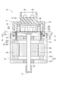
- FIG. 2 is a cross-sectional view of the drive device according to the first embodiment.
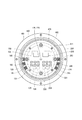
- FIG. 3 is a sectional view taken along line III-III of FIG.
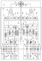
- FIG. 4 is a block diagram showing an ECU according to the first embodiment.
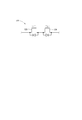
- FIG. 5 is a circuit diagram illustrating a power supply relay according to the first embodiment.
- FIG. 6 is an explanatory diagram illustrating the relationship between the steering torque and the assist torque during driving of the two systems according to the first embodiment.
- FIG. 7 is an explanatory diagram illustrating the relationship between the steering torque and the assist torque in the one-system drive mode according to the first embodiment.
- FIG. 8 is a flowchart illustrating the drive mode selection process according to the first embodiment.
- FIG. 9 is a flowchart illustrating the diagnostic storage process according to the first embodiment.
- FIG. 10 is a time chart for explaining the communication abnormality processing according to the first embodiment.
- FIG. 11 is a time chart for explaining the communication abnormality processing according to the first embodiment.
- FIG. 12 is a time chart for explaining the communication abnormality processing according to the first embodiment.
- FIG. 13 is a time chart for explaining the communication abnormality processing according to the first embodiment.
- FIG. 14 is a flowchart illustrating the drive mode selection process according to the second embodiment.
- FIG. 15 is a time chart for explaining the communication abnormality processing according to the second embodiment.
- FIG. 16 is a time chart for explaining the communication abnormality processing according to the second embodiment.
- FIG. 17 is an explanatory diagram illustrating the relationship between the steering torque and the assist torque according to the reference example.
- FIG. 18 is a time chart illustrating processing at the time of communication abnormality according to a reference example.
- FIGS. 1 to 13 The first embodiment is shown in FIGS. 1 to 13.
- the ECU 10 as a control device is a motor control device that controls the drive of a motor 80 that is a rotary electric machine, and together with the motor 80, serves as a steering device for assisting a steering operation of a vehicle, for example. It is applied to the electric power steering device 8.
- FIG. 1 shows the configuration of a steering system 90 including an electric power steering device 8.
- the steering system 90 includes a steering wheel 91, a steering shaft 92, a pinion gear 96, a rack shaft 97, wheels 98, an electric power steering device 8, and the like, which are steering members.
- the steering wheel 91 is connected to the steering shaft 92.
- the steering shaft 92 is provided with a torque sensor 94 that detects steering torque.
- the torque sensor 94 has a first sensor unit 194 and a second sensor unit 294, and the sensors capable of detecting their own failures are duplicated.
- a pinion gear 96 is provided at the tip of the steering shaft 92.
- the pinion gear 96 meshes with the rack shaft 97.
- a pair of wheels 98 are connected to both ends of the rack shaft 97 via a tie rod or the like.
- the steering shaft 92 connected to the steering wheel 91 rotates.
- the rotational motion of the steering shaft 92 is converted into a linear motion of the rack shaft 97 by the pinion gear 96.
- the pair of wheels 98 are steered at an angle corresponding to the amount of displacement of the rack shaft 97.
- the electric power steering device 8 includes a motor 80, a reduction gear 89 as a power transmission unit that decelerates the rotation of the motor 80 and transmits the rotation to the steering shaft 92, an ECU 10 and the like. That is, the electric power steering device 8 of the present embodiment is a so-called “column assist type", and the steering shaft 92 can be said to be a drive target. It may be a so-called "rack assist type” that transmits the rotation of the motor 80 to the rack shaft 97.
- the motor 80 outputs a part or all of the torque required for steering, and is driven by supplying electric power from batteries 101 and 201 as a power source to decelerate.
- the gear 89 is rotated in the forward and reverse directions.
- the motor 80 is a three-phase brushless motor and has a rotor 860 and a stator 840.
- the motor 80 has a first motor winding 180 and a second motor winding 280.
- the motor windings 180 and 280 have the same electrical characteristics, and are canceled and wound around a common stator 840 with an electric angle of 30 [deg] shifted from each other.
- the motor windings 180 and 280 are controlled so that a phase current whose phase ⁇ is shifted by 30 [deg] is energized.
- the output torque is improved by optimizing the energization phase difference.
- the sixth-order torque ripple can be reduced, and noise and vibration can be reduced.
- heat generation is dispersed and leveled by distributing the current, it is possible to reduce temperature-dependent inter-system errors such as the detected value and torque of each sensor, and increase the amount of current that can be energized. it can.
- the motor windings 180 and 280 may not be canceled and may have different electrical characteristics.
- the combination of the first inverter unit 120 and the first control unit 150 related to the energization control of the first motor winding 180 is combined with the first system L1, the second inverter unit 220 related to the energization control of the second motor winding 280, and the like.
- the combination of the second control unit 250 and the like is referred to as the second system L2.
- the configuration related to the first system L1 is mainly numbered in the 100s
- the configuration related to the second system L2 is mainly numbered in the 200s.
- similar or similar configurations are numbered so that the last two digits are the same.
- first will be described as a subscript "1" and "second” will be described as a subscript "2" as appropriate.
- the drive device 40 is a so-called "mechanical and electrical integrated type" in which the ECU 10 is integrally provided on one side in the axial direction of the motor 80, but the motor 80 and the ECU 10 are separately provided. It may have been.
- the ECU 10 is arranged coaxially with the shaft Ax of the shaft 870 on the side opposite to the output shaft of the motor 80.
- the ECU 10 may be provided on the output shaft side of the motor 80.
- the motor 80 includes a stator 840, a rotor 860, a housing 830 for accommodating these, and the like.
- the stator 840 is fixed to the housing 830, and the motor windings 180 and 280 are wound around the stator 840.
- the rotor 860 is provided inside the stator 840 in the radial direction, and is provided so as to be rotatable relative to the stator 840.
- the shaft 870 is fitted into the rotor 860 and rotates integrally with the rotor 860.
- the shaft 870 is rotatably supported by the housings 830 by bearings 835, 836.
- the end of the shaft 870 on the ECU 10 side projects from the housing 830 toward the ECU 10.
- a magnet 875 is provided at the end of the shaft 870 on the ECU 10 side.
- the housing 830 has a bottomed tubular case 834 including a rear frame end 837 and a front frame end 838 provided on the opening side of the case 834.
- the case 834 and the front frame end 838 are fastened to each other by bolts or the like.
- a lead wire insertion hole 839 is formed in the rear frame end 837. Lead wires 185 and 285 connected to each phase of the motor windings 180 and 280 are inserted into the lead wire insertion holes 839. The lead wires 185 and 285 are taken out from the lead wire insertion holes 839 to the ECU 10 side and connected to the substrate 470.
- the ECU 10 includes a cover 460, a heat sink 465 fixed to the cover 460, a substrate 470 fixed to the heat sink 465, and various electronic components mounted on the substrate 470.
- the cover 460 protects electronic components from external impacts and prevents dust, water, and the like from entering the inside of the ECU 10.
- the cover main body 461 and the connector portions 103 and 203 are integrally formed.
- the connector portions 103 and 203 may be separate from the cover main body 461.
- the terminals 463 of the connector portions 103 and 203 are connected to the substrate 470 via wiring or the like (not shown). The number of connectors and the number of terminals can be appropriately changed according to the number of signals and the like.
- the connector portions 103 and 203 are provided at the axial end of the drive device 40 and open on the side opposite to the motor 80.
- the substrate 470 is, for example, a printed circuit board, and is provided so as to face the rear frame end 837.
- Electronic components for two systems are independently mounted on the board 470 for each system, forming a completely redundant configuration.
- the electronic components are mounted on one substrate 470, but the electronic components may be mounted on a plurality of substrates.
- the surface on the motor 80 side is the motor surface 471
- the surface on the opposite side to the motor 80 is the cover surface 472.
- the switching element 121 constituting the inverter unit 120, the switching element 221 constituting the inverter unit 220, the angle sensor 126, 226, the custom IC 135, 235, and the like are mounted on the motor surface 471.
- the angle sensors 126 and 226 are mounted at locations facing the magnet 875 so that changes in the magnetic field accompanying the rotation of the magnet 875 can be detected.
- Capacitors 128, 228, inductors 129, 229, and microcomputers and the like constituting control units 150 and 250 are mounted on the cover surface 472.
- the microcomputers constituting the control units 150 and 250 are numbered “150” and “250”, respectively.
- Capacitors 128 and 228 smooth the power input from the batteries 101 and 201. Further, the capacitors 128 and 228 assist the power supply to the motor 80 by storing electric charges.
- the capacitors 128 and 228 and the inductors 129 and 229 form a filter circuit to reduce noise transmitted from other devices sharing the battery and reduce noise transmitted from the drive device 40 to other devices sharing the battery.
- the power supply relay 122, 222, the motor relay 125, 225, the current sensor 127, 227, and the like are also mounted on the motor surface 471 or the cover surface 472.
- the ECU 10 includes inverter units 120 and 220, control units 150 and 250, and the like.
- the ECU 10 is provided with connector portions 103 and 203.
- the first connector portion 103 is provided with a first power supply terminal 105, a first ground terminal 106, a first IG terminal 107, a first communication terminal 108, and a first torque terminal 109.
- the first power supply terminal 105 is connected to the first battery 101 via a fuse (not shown).
- the electric power supplied from the positive electrode of the first battery 101 via the first power supply terminal 105 is supplied to the first motor winding 180 via the power supply relay 122, the inverter unit 120, and the motor relay 125. ..
- the first ground terminal 106 is connected to the first ground GND1 which is the ground of the first system inside the ECU 10 and the first external ground GB1 which is the ground of the first system outside the ECU 10.
- the metal body is a common GND plane
- the first external ground GB1 indicates one of the connection points on the GND plane
- the negative electrode of the second battery 201 is also the connection point on this GND plane. Be connected.
- the first IG terminal 107 is connected to the positive electrode of the first battery 101 via a first switch that is on / off controlled in conjunction with a vehicle start switch such as an ignition switch.
- the electric power supplied from the first battery 101 via the first IG terminal 107 is supplied to the first custom IC 135.
- the first custom IC 135 includes a first driver circuit 136, a first circuit power supply 137, a microcomputer monitoring monitor (not shown), a current monitor amplifier (not shown), and the like.
- the first communication terminal 108 is connected to the first vehicle communication circuit 111 and the first vehicle communication network 195.
- the first vehicle communication network 195 and the first control unit 150 are connected to each other so as to be able to transmit and receive via the first vehicle communication circuit 111. Further, the first vehicle communication network 195 and the second control unit 250 are connected so as to be able to receive information, and even if the second control unit 250 fails, the first vehicle communication network 195 including the first control unit 150 is connected. It is configured so that there is no effect.
- the first torque terminal 109 is connected to the first sensor unit 194 of the torque sensor 94.
- the detected value of the first sensor unit 194 is input to the first control unit 150 via the first torque terminal 109 and the first torque sensor input circuit 112.
- the first sensor unit 194 and the first control unit 150 are configured to detect a failure of the torque sensor input circuit system.
- the second connector portion 203 is provided with a second power supply terminal 205, a second ground terminal 206, a second IG terminal 207, a second communication terminal 208, and a second torque terminal 209.
- the second power supply terminal 205 is connected to the positive electrode of the second battery 201 via a fuse (not shown).
- the electric power supplied from the second battery 201 via the second power supply terminal 205 is supplied to the second motor winding 280 via the power supply relay 222, the inverter unit 220, and the motor relay 225.
- the second ground terminal 206 is connected to the second ground GND2, which is the ground of the second system inside the ECU 10, and the second external ground GB2, which is the ground of the second system outside the ECU 10.
- the metal body is a common GND plane
- the second external ground GB2 indicates one of the connection points on the GND plane
- the negative electrode of the second battery 201 is also connected on this GND plane. Connected to the point.
- at least different grids are configured not to connect to the same connection point on the GND plane.
- the second IG terminal 207 is connected to the positive electrode of the second battery 201 via a second switch that is controlled on and off in conjunction with the vehicle start switch.
- the electric power supplied from the second battery 201 via the second IG terminal 207 is supplied to the second custom IC 235.
- the second custom IC 235 includes a second driver circuit 236, a second circuit power supply 237, a microcomputer monitoring monitor (not shown), a current monitor amplifier (not shown), and the like.
- the second communication terminal 208 is connected to the second vehicle communication circuit 211 and the second vehicle communication network 295.
- the second vehicle communication network 295 and the second control unit 250 are connected so as to be able to transmit and receive via the second vehicle communication circuit 211. Further, the second vehicle communication network 295 and the first control unit 150 are connected so as to be able to receive information, and even if the first control unit 150 fails, the second vehicle communication network 295 including the second control unit 250 is affected. It is configured so that there is no.
- the second torque terminal 209 is connected to the second sensor unit 294 of the torque sensor 94.
- the detected value of the second sensor unit 294 is input to the second control unit 250 via the second torque terminal 209 and the second torque sensor input circuit 212.
- the second sensor unit 294 and the second control unit 250 are configured to detect a failure of the torque sensor input circuit system.
- the communication terminals 108 and 208 are connected to separate vehicle communication networks 195 and 295, respectively, but they may be connected to the same vehicle communication network.
- CAN Controller Area Network
- CAN-FD CAN with Flexible Data rate
- FlexRay FlexRay
- the first inverter unit 120 is a three-phase inverter having a switching element 121, and converts the electric power of the first motor winding 180.
- the second inverter unit 220 is a three-phase inverter having a switching element 221 and converts the electric power of the second motor winding 280.
- the first power supply relay 122 is provided between the first power supply terminal 105 and the first inverter unit 120.
- the first motor relay 125 is provided in each phase between the first inverter unit 120 and the first motor winding 180.
- the second power supply relay 222 is provided in each phase between the second power supply terminal 205 and the second inverter unit 220.
- the second motor relay 225 is provided between the second inverter unit 220 and the second motor winding 280.
- the switching elements 121 and 221 and the power supply relays 122 and 222 and the motor relays 125 and 225 are all MOSFETs, but other elements such as IGBTs may be used.
- the first power supply relay 122 is composed of elements having a parasitic diode like a MOSFET
- the two elements 123 and 124 are connected in series so that the directions of the parasitic diodes are opposite to each other. Is desirable.
- the second power supply relay 222 is the same, the illustration is omitted. This makes it possible to prevent the reverse current from flowing when the batteries 101 and 201 are erroneously connected in the opposite directions.
- the power relays 122 and 222 may be mechanical relays.
- the on / off operation of the first switching element 121, the first power supply relay 122, and the first motor relay 125 is controlled by the first control unit 150.
- the on / off operation of the second switching element 221 and the second power supply relay 222 and the second motor relay 225 is controlled by the second control unit 250.
- the first angle sensor 126 detects the rotation angle of the motor 80 and outputs the detected value to the first control unit 150.
- the second angle sensor 226 detects the rotation angle of the motor 80 and outputs the detected value to the second control unit 250.
- the first angle sensor 126 and the first control unit 150, and the second angle sensor 226 and the second control unit 250 are configured to detect failures in their respective angle sensor input circuit systems.
- the first current sensor 127 detects the current applied to each phase of the first motor winding 180.
- the detected value of the first current sensor 127 is amplified by the amplifier circuit in the custom IC 135 and output to the first control unit 150.
- the second current sensor 227 detects the current applied to each phase of the second motor winding 280.
- the detected value of the second current sensor 227 is amplified by the amplifier circuit in the custom IC 235 and output to the second control unit 250.
- the first driver circuit 136 outputs a drive signal for driving the first switching element 121, the first power supply relay 122, and the first motor relay 125 to each element based on the control signal from the first control unit 150.
- the second driver circuit 236 outputs a drive signal for driving the second switching element 221 and the second power supply relay 222 and the second motor relay 225 to each element based on the control signal from the second control unit 250.
- the circuit power supply 137 is connected to the power supply terminal 105 and the IG terminal 107 to supply power to the first control unit 150.
- the circuit power supply 237 is connected to the power supply terminal 205 and the IG terminal 207, and supplies electric power to the second control unit 250.
- the control units 150 and 250 are mainly composed of a microcomputer and the like, and internally include a CPU, ROM, RAM, I / O, etc., which are not shown, and a bus line, etc. connecting these configurations.
- Each process in the control units 150 and 250 may be software processing by executing a program stored in advance in a physical memory device such as a ROM (that is, a readable non-temporary tangible storage medium) on the CPU. However, it may be hardware processing by a dedicated electronic circuit.
- the first control unit 150 and the second control unit 250 are configured to detect their own failures by using, for example, a locked step dual microcomputer or the like.
- the first control unit 150 includes a drive control unit 151, a mode selection unit 152, an abnormality monitoring unit 155, a storage unit 156, and a synchronization processing unit 157.
- the drive control unit 151 controls the energization of the first motor winding 180 by controlling the on / off operation of the first switching element 121. Further, the drive control unit 151 controls the on / off operation of the first power supply relay 122 and the first motor relay 125.
- the second control unit 250 includes a drive control unit 251, a mode selection unit 152, an abnormality monitoring unit 255, a storage unit 256, and a synchronization processing unit 257.
- the drive control unit 251 controls the energization of the second motor winding 280 by controlling the on / off operation of the second switching element 221. Further, the drive control unit 251 controls the on / off operation of the second power supply relay 222 and the second motor relay 225.
- the drive control units 151 and 251 control the drive of the motor 80 by, for example, current feedback control, but the details of the motor control control method may be other than the current feedback control.
- the mode selection units 152 and 252 select the drive mode related to the drive control of the motor 80.
- the drive mode of the present embodiment includes a cooperative drive mode, an independent drive mode, and a single system drive mode, and normally controls the drive of the motor 80 by the cooperative drive mode.
- the normal time is a case where the systems L1 and L2 are normal and two systems can be cooperatively driven, and the control in the cooperative drive mode in the normal time is appropriately referred to as "normal control".
- a case where communication between microcomputers is abnormal or synchronization between systems is not possible is regarded as an incoordination abnormality.
- the determination of incoordination abnormality either communication between microcomputers or synchronization between systems may be omitted.
- the control units 150 and 250 are normal and the communication between the microcomputers is normal, at least one value is shared between the systems, and each system is coordinated to drive the motor 80.
- Control In the present embodiment, the current command value, the current detection value, and the current limit value are shared as control information.
- the first control unit 150 is the master control unit
- the second control unit 250 is the slave control unit
- the current command value calculated by the master first control unit 150 is transmitted to the second control unit 250. Then, the control units 150 and 250 use the same current command value calculated by the first control unit 150.
- the shared current command value may be a value after the current limit or a value before the current limit.
- the current control is performed by the so-called "sum and difference control" that controls the current sum and current difference of the two systems.
- each system independently controls the drive of the motor 80 without using the control information of other systems.
- the one-system drive mode one system is stopped and the drive of the motor 80 is controlled by one system without using the control information of the other system.
- the drive mode in which the motor 80 is driven by one system is referred to as a "single system drive mode".
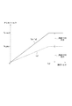
- the assist torque Ta which is the output torque output from the motor 80
- the assist torque Ta is set according to the steering torque Ts.
- the horizontal axis represents the steering torque Ts and the vertical axis represents the assist torque Ta.
- the total output of the two systems is shown by a solid line, and the output of the first system L1 is shown by a broken line.
- the assist torque Ta increases as the steering torque Ts increases in the range where the steering torque Ts reaches the upper limit reaching value Ts2, and the output upper limit in the range where the steering torque Ts reaches the upper limit reaching value Ts2 or more.
- the value is Ta_max2. If the performance and the like of the first system L1 and the second system L2 are the same, the output of the motor 80 is halved by the first system L1 and the second system L2. That is, the output upper limit value Ta_max1 in one system is 1/2 of the output upper limit value Ta_max2 in two systems. Further, the rate of increase of the assist torque Ta with respect to the steering torque Ts in one system is 1/2 of that in the case of driving two systems.
- the assist torque Ta when driving with one system in the independent drive mode, the assist torque Ta is halved when driving with two systems, as shown by the broken line.
- the assist torque Ta increases linearly with the increase of the steering torque Ts in the range up to the output upper limit value Ta_max2, but it may be increased non-linearly.
- Figure 7 shows the output characteristics in the single system drive mode.
- the output when one system is driven by the second system L2 is shown by a solid line, and the total output of the two systems in a normal state is shown by a broken line.
- the single system drive mode when the assist torque Ta with respect to the steering torque Ts is driven by two systems by doubling the rate of increase of the assist torque Ta with respect to the steering torque Ts within the range where the steering torque Ts reaches the upper limit reaching value Ts1. It is the same as.
- the assist torque Ta becomes the output upper limit value Ta_max1 in the one-system drive regardless of the steering torque Ts, and the assist torque Ta becomes smaller than in the two-system drive.
- the output upper limit value Ta_max1 in the one-system drive mode may be increased in the range of the output upper limit value Ta_max2 or less in the two-system drive.
- the one-system drive performed when another system is abnormal is referred to as “backup control” and is also described as “BU control” in the figure.
- BU control changing the output characteristic and increasing the rate of increase of the assist torque Ta with respect to the steering torque Ts and at least one of the output upper limits.
- the abnormality monitoring unit 155 monitors the abnormality of the first system L1 which is its own system. Further, when an abnormality that should stop the own system occurs, the first control unit 150 turns off at least one of the first inverter unit 120, the first power supply relay 122, and the first motor relay 125.
- the abnormality monitoring unit 155 monitors the communication status with the second control unit 250 and the operating status of the second system L2.
- a circuit that stops its own system when an abnormality in the second system L2 is detected as a method for monitoring the operating state of the second system L2 for example, a second inverter unit 220, a second power supply relay 222, and a second motor relay 225.
- at least one of the communication lines related to the communication between the microcomputers is monitored, and it is determined whether or not the emergency stop is performed.
- another system relay monitoring circuit 139 that acquires the second relay gate signal Vrg2 output from the second driver circuit 236 to the second power supply relay 222 is provided, and the second is based on the second relay gate signal Vrg2. Monitor the status of the power relay 222.
- the abnormality monitoring unit 255 monitors the abnormality of the second system L2, which is its own system. Further, when an abnormality that should stop the own system occurs, the second control unit 250 turns off at least one of the second inverter unit 220, the second power supply relay 222, and the second motor relay 225.
- the abnormality monitoring unit 255 monitors the communication status with the first control unit 150 and the operating status of the first system L1.
- a circuit that stops the own system when an abnormality of the first system L1 is detected for example, the first inverter unit 120, the first power supply relay 122, and the first motor relay 125.
- the state of at least one of the communication lines related to the communication between microcomputers, and it is determined whether or not the emergency stop is performed.
- another system relay monitoring circuit 239 that acquires the first relay gate signal Vrg1 output from the first driver circuit 136 to the first power supply relay 122 is provided, and the first is based on the first relay gate signal Vrg1. Monitor the status of the power relay 122.
- the intermediate voltage of the two elements 123 and 124 constituting the power supply relay 122 and the control unit 150 are output.
- the relay drive signal or the post-relay voltage between the power supply relay 122 and the inverter unit 120 may be used. The same applies to the monitoring of the second system L2 in the first control unit 150.
- the information acquired from the other system relay monitoring circuit is “other system relay information”
- the monitoring of the operating status of the other system based on the other system relay information is “other system relay monitoring”
- the monitored relay is “other system relay monitoring”. It is called “other system relay”.
- the state in which the other system relay is turned on is referred to as “other system relay Hi”
- the state in which the other system relay is turned off is referred to as “other system relay Lo”.
- the abnormality monitoring unit 155, 255 determines that the other system is abnormal when a communication abnormality between the microcomputers has occurred and the relay information of the other system is abnormal. Further, in the abnormality monitoring units 155 and 255, when a communication error between microcomputers has occurred and the relay information of another system is normal, the control unit of the other system is normal and a communication error between microcomputers has occurred. Is determined. That is, in the present embodiment, the communication state between microcomputers and the relay monitoring of other systems determine whether the state in which communication is not possible is due to an abnormality in the control unit of the other system or due to an abnormality in communication between microcomputers.
- the storage unit 156 is a non-volatile memory, and stores abnormality information related to the abnormality detected by the abnormality monitoring unit 155.
- the storage unit 256 is a non-volatile memory, and stores abnormality information related to the abnormality detected by the abnormality monitoring unit 255.
- the abnormality information stored in the storage units 156 and 256 includes information related to communication abnormality between microcomputers, information related to other system stoppage, and the like.
- the abnormality information stored in the storage units 156 and 256 is used for abnormality analysis.
- the abnormal information will be referred to as "diag" as appropriate.
- the synchronization processing units 157 and 257 perform synchronization processing for synchronizing the control timings of the control units 150 and 250.
- the first control unit 150 has a clock generation circuit (not shown), and generates a drive timing based on the generated clock signal.
- the synchronization processing unit 157 generates a synchronization signal for synchronizing the drive timing with another system, and transmits the synchronization signal to the second control unit 250.
- the second control unit 250 has a clock generation circuit (not shown) and generates a drive timing based on the generated clock signal.
- the synchronization processing unit 257 corrects the drive timing so that it matches the first system L1 based on the synchronization signal transmitted from the first control unit 150.
- the synchronization signal may be generated outside the control units 150 and 250, and the details of the synchronization process may be different. Further, as the communication line used for transmitting and receiving the synchronization signal, a dedicated communication line may be used, or a signal line used for transmitting and receiving other information may be shared.
- the state in which communication cannot be performed between the control units 150 and 250 may occur not only due to an internal failure of the ECU 10 but also due to an abnormality of the power supply device external to the ECU 10 such as an abnormality of the batteries 101 and 201 and a disconnection of the harness.
- the cooperative drive is performed using the information of other systems acquired by the communication between the microcomputers, it is desirable to promptly switch the drive mode when the communication between the microcomputers is abnormal.
- the abnormality information is stored as a diagnostic at the same time as the drive mode is switched, the abnormality history remains even if it is a temporary abnormality such as a momentary power interruption.
- the output characteristics are changed by backup control, there is a risk of overoutput when the system in which a temporary abnormality has occurred is restored.
- FIG. 17 as a reference example, when one system drive is already performed in the second system L2 and the output due to the independent drive of the first system L1 is added, the steering torque Ts reaches the upper limit. In the range up to the value Ts2, the output becomes excessive from the normal time.
- the output of the two systems in the cooperative drive mode is a broken line
- the output of the second system L2 in the single system drive mode is a two-dot chain line
- the output of the first system L1 in the independent drive mode is a one-dot chain line.
- the output of the two systems in which the output of the second system L2 is added to the output of the first system L1 in the one-system drive mode is shown by a solid line.
- the drive mode is changed when the abnormality is confirmed in the first stage, and diagnostic storage is performed when the abnormality is confirmed in the second stage.
- the time and the abnormality confirmation time of the second stage are different. Specifically, the abnormality confirmation time (for example, 3 [s]) of the second stage is made longer than the abnormality confirmation time (for example, several [ms]) of the first stage. It is preferable that the abnormality confirmation time of the first stage is as short as possible, and the abnormality confirmation time of the second stage is set according to the time required for restarting by resetting the microcomputer of another system. In detail, it is set to a time longer than the time required for restarting by the amount of time allowed as a power interruption. In addition, when another system has already shifted to backup control, overoutput is prevented by stopping the assist of the own system. Further, in the present embodiment, the time until the other system stop confirmation determination is made is equal to the abnormality confirmation time of the second stage.
- step S101 The drive mode selection process of the present embodiment will be described with reference to the flowchart of FIG. This process is executed by the control units 150 and 250 at a predetermined cycle.
- step S101 the “step” in step S101 is omitted and simply referred to as the symbol “S”. The same applies to the other steps.
- control units 150 and 250 determine whether or not the communication between the microcomputers is abnormal. If it is determined that the communication between the microcomputers is abnormal (S101: YES), the process proceeds to S107. When it is determined that the communication between the microcomputers is normal (S101: NO), the process proceeds to S102. If the communication between the microcomputers is normally determined and the counters Ct1, Ct2, and Ct3 described later are counted, the data is reset.
- control units 150 and 250 determine whether or not cooperative driving is in progress. When it is determined that the cooperative drive is in progress (S102: YES), the process proceeds to S103 and the cooperative drive is continued. If it is determined that the cooperative drive is not in progress (S102: NO), the process proceeds to S104.
- control units 150 and 250 determine whether or not another system has shifted to backup control. When it is determined that the other system has shifted to backup control (S104: YES), the shift to S105 is performed, and the drive mode is set to assist stop. If it is determined that the other system has not shifted to backup control (S104: NO), the system shifts to S106 and the drive mode of the own system is set to the independent drive mode.
- the control units 150 and 250 determine whether or not the first-stage communication abnormality counter Ct1 is larger than the first-stage confirmation determination value TH1.
- the first-stage confirmation determination value TH1 is set according to the first-stage abnormality confirmation time. When it is determined that the first-stage communication abnormality counter Ct1 is equal to or less than the first-stage confirmation determination value TH1 (S109: NO), the process of S110 is not performed and this routine is terminated. When it is determined that the first-stage abnormality confirmation counter Ct1 is larger than the first-stage confirmation determination value TH1 (S109: YES), the process proceeds to S110, the first-stage communication abnormality is confirmed, and the drive mode is set to independent drive. For example, the first-stage confirmation determination value TH1 may be set to 0, and the mode may be shifted to the independent drive mode immediately after the communication abnormality between the microcomputers is detected.
- the control units 150 and 250 determine whether or not the other system relay is Lo. When it is determined that the other system relay is Hi (S111: NO), this routine is terminated without performing the processing after S113. If the other system monitoring counter Ct3 is counted, it is reset. When it is determined that the other system relay is Lo (S111: YES), the process proceeds to S112 and the other system monitoring counter Ct3 is incremented.
- the control units 150 and 250 determine whether or not the other system monitoring counter Ct3 is larger than the other system abnormality confirmation determination value TH3.
- the other system abnormality confirmation determination value TH3 is set according to the time for shifting from the independent drive to the backup control.
- the processing of S114 is not performed and this routine is terminated.
- the process shifts to S114 and shifts to backup control. Further, the other system stop is stored in the storage units 156 and 256 as a diagnosis.
- the diagnostic storage process of this embodiment will be described with reference to the flowchart of FIG. This process is executed by the control units 150 and 250 at a predetermined cycle.
- the control units 150 and 250 determine whether or not the communication between the microcomputers is abnormal. When it is determined that the communication between the microcomputers is normal (S151: NO), the processing after S152 is not performed. If the second-stage abnormality confirmation counter Ct2, which will be described later, is counted, it is reset. When it is determined that the communication between the microcomputers is abnormal (S151: YES), the process proceeds to S152.
- control units 150 and 250 determine whether or not the communication abnormality in the first stage is confirmed. If it is determined that the communication abnormality in the first stage has not been confirmed (S152: NO), the processing after S152 is not performed, and this routine is terminated. When it is determined that the communication abnormality in the first stage is confirmed (S152: YES), the process proceeds to S153.
- control units 150 and 250 determine whether or not the own system is in backup control. If it is determined that the own system is in backup control (S153: YES), this routine is terminated without performing the processing after S154. If it is determined that the own system is not in backup control (S153: NO), the process proceeds to S154.
- the control units 150 and 250 determine whether or not the power latch is in progress. Even after the start switch is turned off, the control units 150 and 250 continue to be on and perform end processing and the like, and turn off after the end process is completed. In the present embodiment, the state in which the control units 150 and 250 are turned on after the start switch is turned off is defined as "power latching". If it is determined that the power latch is in progress (S154: YES), the processing after S155 is not performed, and this routine is terminated. If it is determined that the power latch is not in progress (S154: NO), the process proceeds to S155.
- control units 150 and 250 determine whether or not the other system relay is Lo. If it is determined that the other system relay is Lo (S155: YES), the processing after S156 is not performed, and this routine is terminated. When it is determined that the other system relay is Hi (S155: NO), the process proceeds to S156.
- the control units 150 and 250 increment the second-stage communication abnormality counter Ct2.
- the second-stage confirmation determination value TH2 is set according to the second-stage abnormality confirmation time, and is set to the same value as the other system abnormality confirmation determination value TH3.
- the process of S158 is not performed and this routine is terminated.
- the process proceeds to S158 to confirm the second-stage communication abnormality, and the communication abnormality between the microcomputers is stored as a diagnostic. Store in units 156 and 256.
- S153 to S155 correspond to the diagnostic storage mask condition determination, and when the positive determination is made in S153, the other system stop has already been confirmed, so that the diagnostic storage mask condition related to the communication abnormality between the microcomputers is set. It is determined that it is established. If an affirmative judgment is made in S155, it is determined that the other system relay is Lo, communication is not possible due to the other system stop instead of communication between microcomputers, and the diagnostic storage mask condition related to the communication abnormality between microcomputers is satisfied. .. Further, when the affirmative judgment is made in S154, it is determined that the diagnostic storage mask condition related to the communication abnormality between the microcomputers is satisfied because the power latch is in progress and the IG is normally turned off. If a negative determination is made in S153 to S155, it is determined that the diagnostic storage mask condition is not satisfied. The order of S153 to S155 may be changed, or some processes may be omitted.
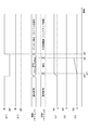
- the processing at the time of communication abnormality will be described based on the time charts of FIGS. 10 to 13.
- the power supply state to the first control unit 150 (described as “IG-1” in the figure), the power supply state to the second control unit 250 (described as “IG-2” in the figure), and the first
- the drive mode of the first system L1 is the drive mode of the second system L2, the first stage communication abnormality counter Ct1, the second stage communication abnormality counter Ct2, and the other system monitoring counter Ct3.
- the counters Ct1, Ct2, and Ct3 will be values in the second control unit 250.
- the state in which power is supplied to the control units 150 and 250 is referred to as "power on”
- the state in which power supply is interrupted is referred to as "power off”. 11 to 14 and 18 are substantially the same.
- one counter is used to simultaneously perform abnormal case treatment and diagnostic memory.
- the microcomputer of the first control unit 150 is stopped.
- the second control unit 250 detects the communication abnormality between the microcomputers and starts counting the abnormality counter.
- the second control unit 250 determines that the first system L1 which is the partner system has stopped, and stores the abnormality information of the partner system stop as a diagnosis. At the same time, shift from normal control to backup control.
- the abnormality that occurred at time x90 is a momentary power interruption
- the microcomputer of the first control unit 150 is restarted at time x92.
- the first control unit 150 after restarting drives the motor 80 in the cooperative drive mode or the independent drive mode.
- the diagnosis of the other system stop is stored, so that there is a possibility that unnecessary measures such as repair or replacement of the first control unit 150 may be performed.
- the abnormality confirmation related to the change of the drive mode and the abnormality confirmation related to the diagnostic memory are separated, and a two-stage confirmation is performed in which different confirmation times are set. Further, the transition from the independent drive mode to the backup control is based on the information of monitoring other systems, and the drive mode is switched and the diagnosis is stored by using a total of three counters.
- the microcomputer of the first control unit 150 when the power supply of the first system L1 is momentarily interrupted at time x10, the microcomputer of the first control unit 150 is stopped.
- the second control unit 250 detects a communication abnormality between microcomputers and starts counting the first-stage communication abnormality counter Ct1.
- the first-stage communication abnormality counter Ct1 exceeds the first-stage confirmation determination value TH1 at time x11, the second control unit 250 switches the drive mode to the independent drive mode. In the independent drive mode, the output characteristics are not changed, so that when the first system L1 is stopped, the output is halved from the normal state.
- the microcomputer of the first control unit 150 while the microcomputer of the first control unit 150 is restarting, the other system relay becomes Lo, so the counting of the other system monitoring counter Ct3 is started. At this time, since the other system relay is Lo and the diagnostic storage mask condition is satisfied, the second-stage communication abnormality counter Ct2 is not counted.
- the other system relay becomes Hi, so the other system monitoring counter Ct3 is reset.
- the first control unit 150 acquires the information that the second system L2 is in the independent drive mode by the communication between the microcomputers, the first control unit 150 performs the drive control of the motor 80 in the independent drive mode.
- the temporary stop and restart of the first control unit 150 due to a momentary power interruption or the like is left in the storage unit 256 of the second control unit 250 with an erroneous diagnosis that the first control unit 150 is abnormal. Can be prevented.
- the drive control of the motor 80 in the two systems is performed in the independent drive mode, so that it is possible to prevent an output decrease and an overoutput.
- FIG. 11 is an example in which the power supply of the first system L1 is turned off at time x20 and the off state is continued.
- the processing of the time x20 and the time x21 is the same as the processing of the time x10 and the time x11 in FIG.
- Lo of the other system relay is continued.
- the other system monitoring counter Ct3 exceeds the other system abnormality confirmation determination value TH3 at the time x22
- the second control unit 250 stores the other system stop as a diagnosis in the storage unit 256.
- the drive mode is switched from the independent drive mode to the single system drive mode, the backup control is shifted, and the output characteristics are changed.
- FIG. 12 is an example when a communication error between microcomputers occurs at time x30.
- the power supply is on for both the systems L1 and L2, and the counters Ct1, Ct2, and Ct3 have the same values in the control units 150 and 250.
- the count of the first-stage communication error counter Ct1 is started.
- the first-stage communication abnormality counter Ct1 exceeds the first-stage confirmation determination value TH1 at time x31, both the systems L1 and L2 shift to the independent drive mode.
- the control units 150 and 250 store the inter-microcomputer communication abnormality as a diagnosis in their own storage units 156 and 256, respectively. For example, considering that the information stored in the storage units 156 and 256 is used for failure analysis and the like, there is no actual harm even if the diagnostic storage timing is delayed from the switching of the drive mode.
- FIG. 13 is an example in which the power supply of the first system L1 is restored after the backup control shift.
- the processing of time x40 to time x42 is the same as the processing of time x20 to time x22 in FIG.
- the first control unit 150 is activated.
- the first control unit 150 acquires the information that the second system L2 has been shifted to the backup control by inter-microcomputer communication
- the first control unit 150 drives the motor 80 by the first system L1 so as not to cause excessive assist.
- the assist is stopped without any control. Since the microcomputer of the first control unit 150 is operating, processing other than drive control of the motor 80, such as abnormality monitoring, may be performed. Further, in this case, the other system is stopped for a relatively long time, and the other system stop remains as a diagnosis.
- control units 150 and 250 of the ECU 10 of the present embodiment include drive control units 151 and 251, an abnormality monitoring unit 155 and 255, and a storage unit 156 and 256.
- the drive control units 151 and 251 control the operation of the motor 80 to be controlled.
- the abnormality monitoring units 155 and 255 perform abnormality monitoring.
- the storage units 156 and 256 store abnormality information according to the abnormality monitoring result.
- a timer related to the abnormality determination determination and a timer related to the abnormality memory confirmation determination are separately provided, and the timing of the abnormality determination determination and the timing of the abnormality memory confirmation are different and monitored.
- the time from the detection of the target abnormality to the determination of the abnormal memory confirmation is longer than the time from the detection of the monitored abnormality to the determination of the determination of the treatment at the time of abnormality. As a result, the probability that an erroneous abnormality history is stored can be reduced.
- the ECU 10 is provided with a plurality of control units 150 and 250 having drive control units 151 and 251, abnormality monitoring units 155 and 255, and storage units 156 and 256.
- the monitored abnormality of the present embodiment is a communication abnormality or a synchronization abnormality between the control units 150 and 250, which is an incoordination abnormality.
- the time from the detection of the incoordination abnormality to the determination of the abnormal memory confirmation is set according to the time required for restarting the control units 150 and 250. As a result, a temporary abnormality due to an external factor such as a momentary power interruption is not stored, so that the probability that an erroneous abnormality history is stored can be reduced.
- the control units 150 and 250 mask the abnormal memory confirmation determination when the other control units are stopped. Specifically, when another control unit is stopped, the time of the abnormality determination time in the second stage is not measured, and the abnormality information related to the incoordination abnormality is not stored. As a result, it is possible to avoid erroneously memorizing a state in which coordination is not possible due to other system stoppage or normal IG off as an incoordination abnormality.
- the control units 150 and 250 can monitor the control status of the motor 80 by another control unit based on other system relay information acquired separately from the communication between the control units 150 and 250 to be monitored. Further, when an incoordination abnormality has occurred and the other system stop is confirmed based on the other system relay information, the control units 150 and 250 use the information related to the other system stop as the abnormality information and their own storage units 156. Store in 256. As a result, information related to the shutdown of other systems can be appropriately stored.
- the time from the detection of the incoordination abnormality to the determination of other system stop confirmation is longer than the time from the detection of the incoordination abnormality to the determination of the treatment confirmation at the time of abnormality. As a result, the probability that an erroneous abnormality history is stored can be reduced. Further, the time from the detection of the incoordination abnormality to the determination of stopping the other system is set according to the time required for restarting the control units 150 and 250. As a result, a temporary abnormality due to an external factor such as a momentary power interruption is not stored, so that the probability that an erroneous abnormality history is stored can be reduced.
- the control units 150 and 250 shift to backup control different from the emergency treatment.
- the abnormal action of the present embodiment is a shift to the independent drive mode, and does not shift to the backup control until it is determined that the other system is stopped. Further, the control units 150 and 250 maintain the stopped state of the own system when the other system shifts to the backup control at the time of its own activation. As a result, it is possible to avoid inconsistency in control when returning from the temporary stop state.
- the output characteristics are changed so as to supplement the output of other systems.
- the independent drive mode in which the output characteristics are not changed without shifting to the backup control until the other system stop confirmation judgment is made, it is possible to prevent overoutput when the other system recovers from the temporary stop.
- overoutput can be prevented by maintaining the stopped state of the own system.
- the second embodiment is shown in FIGS. 14 to 16.
- the drive mode selection process is different from the above-described embodiment, and this point will be mainly described.
- the cooperative drive mode is restored.
- the drive mode selection process of the present embodiment will be described with reference to the flowchart of FIG.
- the processing of S201 and S202 is the same as the processing of S101 and S102 in FIG. If the communication between the microcomputers is abnormal, the process proceeds to S206. Further, when the communication between the microcomputers is normal and the cooperative drive is in progress, the process shifts to S204 to continue the cooperative drive, and when the cooperative drive is not in progress, the process shifts to S203.
- control units 150 and 250 determine whether or not the cooperative return condition is satisfied. When it is determined that the cooperative return condition is satisfied (S203: YES), the process proceeds to S204 and the drive mode is switched to the cooperative drive mode. When it is determined that the cooperative return condition is not satisfied (S203: NO), the process proceeds to S205 and the drive mode is set to the independent drive mode.
- the processing of S206 to S213 is the same as the processing of S107 to S114 in FIG.
- the command deviation ⁇ I * which is the absolute value of the difference between the first current command value calculated by the first control unit 150 and the second current command value calculated by the second control unit 250, deviates. If it is determined that it is smaller than the determination value ⁇ I_th, it is considered that there is no command deviation between the systems, and it is determined that cooperative return is possible. Further, when the first current limit value Ilim1 calculated by the first control unit 150 and the second current limit value Ilim2 calculated by the second control unit 250 are both larger than the return determination value, it is determined that cooperative return is possible. To do. Further, when the steering torque Ts is smaller than the non-steering determination value Ts_th, it is determined that the cooperative return is possible. Furthermore, when the vehicle speed V is smaller than the vehicle speed determination value V_th, it is determined that cooperative return is possible.
- the command deviation ⁇ I * is smaller than the deviation determination value ⁇ I_th
- the current limit values Illim1 and Ilim2 are larger than the return determination value
- the steering torque Ts is smaller than the non-steering determination value Ts_th
- the vehicle speed V is the vehicle speed determination. If it is smaller than the value V_th, it is determined that "the cooperative return condition is satisfied".
- the communication between the microcomputers returns to normal after the communication abnormality between the microcomputers occurs, it is considered that the "incoordination abnormality has been resolved".
- FIG. 15 is an example in the case where a momentary power interruption occurs as in FIG. 10, and the processing of time x50 to time x52 is the same as the processing of time x10 to time x12 in FIG.
- both the systems L1 and L2 switch the drive mode from the independent drive mode to the cooperative drive mode and return to the normal control.
- FIG. 16 is an example in which the power supply of the first system L1 is restored after the backup control shift as in FIG.
- the processing of time x60 to time x62 is the same as the processing of time x40 to time x42 in FIG.
- both the systems L1 and L2 are set to the independent drive mode.
- both the systems L1 and L2 switch the drive mode from the independent drive mode to the cooperative drive mode and return to the normal control.
- the period during which the power supply is stopped is longer than the other system abnormality confirmation time corresponding to the other system abnormality confirmation determination value TH3, the diagnosis of the other system stop remains.
- control units 150 and 250 return to the normal control when the incoordination abnormality is resolved and the cooperative return condition is satisfied.
- the control units 150 and 250 return to the normal control when the incoordination abnormality is resolved and the cooperative return condition is satisfied.
- the control units 150 and 250 return to the normal control when the incoordination abnormality is resolved and the cooperative return condition is satisfied.
- the ECU 10 is a "control device”
- the motor 80 is a "control target”
- the drive control units 151 and 251 are “operation control units”
- the communication abnormality between microcomputers is “communication abnormality between control units”
- other system relays The information corresponds to "other system monitoring information”
- restarting by resetting the microcomputer corresponds to "restarting the control unit”.
- the monitored abnormality is an uncoordinated abnormality
- the uncoordinated abnormality includes an inter-microcomputer communication abnormality and a synchronization abnormality.
- either the communication abnormality between the microcomputers or the synchronization abnormality may be regarded as an incoordination abnormality.
- the monitored abnormality may be an abnormality other than the incoordination abnormality.
- the other system monitoring information is the other system relay information.
- the other system monitoring information may use information other than the other system relay information capable of monitoring the state of the other system.
- the relay information of the other system is directly acquired by using the monitoring circuit of the other system.
- the other system monitoring information may be acquired by a communication separate from the communication for communicating the shared control information.
- the determination timing is different, so that the abnormality determination determination and the abnormal memory confirmation determination are different.
- the determination condition other than the determination timing may be different so that the abnormality treatment confirmation determination and the abnormality memory confirmation determination may be different.
- the emergency treatment is a shift to the independent drive mode.
- the emergency treatment may be a treatment other than the transition to the independent drive mode.
- the abnormality confirmation time of the second stage and the other system stop confirmation determination time are equal. In other embodiments, the abnormality confirmation time of the second stage and the other system stop confirmation determination time may be different.
- the steering state was determined based on the steering torque.
- the steering state may be determined based on the steering wheel speed, the motor speed, or the rack speed, not limited to the steering torque.
- the steering state may be determined based on the current command value and the current detection value.
- the current command value When the value of the current command value is large, it is highly probable that the vehicle is being steered. Therefore, when the current command value is larger than the determination threshold value, or when the current command value is smaller than the determination threshold value, it is determined that the vehicle is in a non-steering state. The same applies to the current detection value.
- the steering state may be determined using two or more of the steering torque, the steering wheel speed, the motor speed, the rack speed, the current command value and the current detection value.
- the command deviation, the current limit value, the steering torque, and the vehicle speed are used as the cooperative return determination conditions.
- the cooperative return determination condition a part of the above four determination conditions illustrated may be omitted, or another determination condition may be added, for example, an item related to the behavior of the vehicle. Other items such as lateral G of the vehicle and yaw rate may be added.
- the current command value, the current detection value, and the current limit value are shared between the systems in the cooperative drive mode. In other embodiments, the current limit value may not be shared in the coordinated drive mode.
- the first control unit 150 is the master control unit
- the second control unit 250 is the slave control unit
- the current command values calculated by the first control unit 150 are the control units 150 and 250. Used in.
- the current command value is not shared, and the current command value of the own system may be used even in the cooperative drive mode. Further, values other than the current command value, the current detection value, and the current limit value may be shared.
- two motor windings, two inverter units and two control units are provided.
- the motor windings may be one or more.
- the number of inverter units and control units may be one or three or more.
- one control unit is provided for a plurality of motor windings and an inverter unit, or a plurality of inverter units and a motor winding are provided for one control unit, and so on.
- the number of units and the number of control units may be different.
- a power supply is provided for each system and the ground is separated.
- one power source may be shared by a plurality of systems.
- a plurality of systems may be connected to a common ground.
- the rotary electric machine is a three-phase brushless motor. In other embodiments, the rotary electric machine is not limited to a brushless motor. Further, it may be a so-called motor generator that also has a function of a generator.
- the control device is applied to an electric power steering device. In another embodiment, the control device may be applied to a steering device other than the electric power steering device that controls steering, such as a steer-by-wire device. Further, it may be applied to an in-vehicle device other than the steering device or a device other than the in-vehicle device.
- the controls and methods thereof described in the present disclosure are realized by a dedicated computer provided by configuring a processor and memory programmed to perform one or more functions embodied by a computer program. May be done.
- the controls and methods thereof described in the present disclosure may be implemented by a dedicated computer provided by configuring the processor with one or more dedicated hardware logic circuits.
- the control unit and method thereof described in the present disclosure may be a combination of a processor and memory programmed to perform one or more functions and a processor composed of one or more hardware logic circuits. It may be realized by one or more dedicated computers configured.
- the computer program may also be stored in a computer-readable non-transitional tangible storage medium as an instruction executed by the computer. As described above, the present disclosure is not limited to the above-described embodiment, and can be implemented in various forms without departing from the spirit thereof.
Landscapes
- Engineering & Computer Science (AREA)
- Power Engineering (AREA)
- Physics & Mathematics (AREA)
- General Physics & Mathematics (AREA)
- Power Steering Mechanism (AREA)
- Control Of Electric Motors In General (AREA)
Priority Applications (2)
| Application Number | Priority Date | Filing Date | Title |
|---|---|---|---|
| CN202080057194.2A CN114269631B (zh) | 2019-08-15 | 2020-08-11 | 控制装置 |
| US17/650,633 US11949360B2 (en) | 2019-08-15 | 2022-02-10 | Control device |
Applications Claiming Priority (2)
| Application Number | Priority Date | Filing Date | Title |
|---|---|---|---|
| JP2019-149071 | 2019-08-15 | ||
| JP2019149071A JP7136046B2 (ja) | 2019-08-15 | 2019-08-15 | 制御装置 |
Related Child Applications (1)
| Application Number | Title | Priority Date | Filing Date |
|---|---|---|---|
| US17/650,633 Continuation US11949360B2 (en) | 2019-08-15 | 2022-02-10 | Control device |
Publications (1)
| Publication Number | Publication Date |
|---|---|
| WO2021029405A1 true WO2021029405A1 (ja) | 2021-02-18 |
Family
ID=74569664
Family Applications (1)
| Application Number | Title | Priority Date | Filing Date |
|---|---|---|---|
| PCT/JP2020/030601 Ceased WO2021029405A1 (ja) | 2019-08-15 | 2020-08-11 | 制御装置 |
Country Status (4)
| Country | Link |
|---|---|
| US (1) | US11949360B2 (https=) |
| JP (1) | JP7136046B2 (https=) |
| CN (1) | CN114269631B (https=) |
| WO (1) | WO2021029405A1 (https=) |
Families Citing this family (3)
| Publication number | Priority date | Publication date | Assignee | Title |
|---|---|---|---|---|
| KR102637909B1 (ko) * | 2019-01-23 | 2024-02-19 | 에이치엘만도 주식회사 | 전동식 파워 스티어링 시스템의 리던던시 회로 |
| JP7375357B2 (ja) * | 2019-07-30 | 2023-11-08 | マツダ株式会社 | 車両制御システム |
| CN119487806A (zh) * | 2022-07-19 | 2025-02-18 | 日立安斯泰莫株式会社 | 状态判定装置 |
Citations (3)
| Publication number | Priority date | Publication date | Assignee | Title |
|---|---|---|---|---|
| JP2017175792A (ja) * | 2016-03-24 | 2017-09-28 | 株式会社デンソー | 電力変換装置 |
| WO2018012417A1 (ja) * | 2016-07-11 | 2018-01-18 | 株式会社デンソー | モータ制御装置、モータ駆動システム、及び、モータ制御方法 |
| JP2019004682A (ja) * | 2017-02-28 | 2019-01-10 | 株式会社デンソー | モータ制御装置、モータ駆動システム、及び、モータ制御方法 |
Family Cites Families (16)
| Publication number | Priority date | Publication date | Assignee | Title |
|---|---|---|---|---|
| JP4306765B2 (ja) * | 2007-06-08 | 2009-08-05 | 株式会社デンソー | 故障診断用情報収集装置 |
| JP5496257B2 (ja) * | 2012-06-11 | 2014-05-21 | 三菱電機株式会社 | 電動パワーステアリング制御装置 |
| JP5765589B2 (ja) * | 2013-03-11 | 2015-08-19 | 株式会社デンソー | 電力変換装置 |
| JP6540227B2 (ja) * | 2015-05-21 | 2019-07-10 | 株式会社ジェイテクト | 車両用制御装置 |
| JP6406155B2 (ja) * | 2015-07-31 | 2018-10-17 | 株式会社デンソー | センサ装置、および、これを用いた電動パワーステアリング装置 |
| JP7024223B2 (ja) * | 2016-07-11 | 2022-02-24 | 株式会社デンソー | モータ制御装置、モータ駆動システム、及び、モータ制御方法 |
| US10668945B2 (en) | 2016-07-11 | 2020-06-02 | Denso Corporation | Motor control apparatus, motor drive system, and motor control method |
| JP6911561B2 (ja) * | 2016-07-11 | 2021-07-28 | 株式会社デンソー | モータ制御装置、モータ駆動システム、及び、モータ制御方法 |
| JP6586930B2 (ja) * | 2016-08-04 | 2019-10-09 | トヨタ自動車株式会社 | 車両走行制御装置 |
| JP7027808B2 (ja) | 2016-11-11 | 2022-03-02 | 株式会社デンソー | 回転電機制御装置、および、これを用いた電動パワーステアリング装置 |
| WO2019069394A1 (ja) * | 2017-10-04 | 2019-04-11 | 三菱電機株式会社 | 電力変換装置 |
| KR101991257B1 (ko) * | 2017-10-27 | 2019-06-21 | 주식회사 만도 | 이중 권선형 모터 제어장치 및 제어방법 |
| JP7205352B2 (ja) | 2019-04-02 | 2023-01-17 | 株式会社デンソー | 回転電機制御装置、および、これを用いた電動パワーステアリング装置 |
| JP7120511B2 (ja) * | 2019-10-03 | 2022-08-17 | Smc株式会社 | 異常検出システム及び異常検出方法 |
| JP7338785B2 (ja) * | 2020-03-16 | 2023-09-05 | 株式会社デンソー | センター装置,配信パッケージの生成方法及び配信パッケージ生成用プログラム |
| JP7347380B2 (ja) * | 2020-09-09 | 2023-09-20 | トヨタ自動車株式会社 | 処理装置、通信システム、及び処理装置用プログラム |
-
2019
- 2019-08-15 JP JP2019149071A patent/JP7136046B2/ja active Active
-
2020
- 2020-08-11 WO PCT/JP2020/030601 patent/WO2021029405A1/ja not_active Ceased
- 2020-08-11 CN CN202080057194.2A patent/CN114269631B/zh active Active
-
2022
- 2022-02-10 US US17/650,633 patent/US11949360B2/en active Active
Patent Citations (3)
| Publication number | Priority date | Publication date | Assignee | Title |
|---|---|---|---|---|
| JP2017175792A (ja) * | 2016-03-24 | 2017-09-28 | 株式会社デンソー | 電力変換装置 |
| WO2018012417A1 (ja) * | 2016-07-11 | 2018-01-18 | 株式会社デンソー | モータ制御装置、モータ駆動システム、及び、モータ制御方法 |
| JP2019004682A (ja) * | 2017-02-28 | 2019-01-10 | 株式会社デンソー | モータ制御装置、モータ駆動システム、及び、モータ制御方法 |
Also Published As
| Publication number | Publication date |
|---|---|
| JP7136046B2 (ja) | 2022-09-13 |
| CN114269631B (zh) | 2024-04-16 |
| CN114269631A (zh) | 2022-04-01 |
| JP2021035074A (ja) | 2021-03-01 |
| US11949360B2 (en) | 2024-04-02 |
| US20220166365A1 (en) | 2022-05-26 |
Similar Documents
| Publication | Publication Date | Title |
|---|---|---|
| CN111791943B (zh) | 旋转电机控制装置和使用其的电动助力转向设备 | |
| CN114223131B (zh) | 旋转电机控制装置 | |
| US11088532B2 (en) | Control device | |
| US11949360B2 (en) | Control device | |
| US11479291B2 (en) | Control apparatus | |
| US11626780B2 (en) | Electronic control device | |
| JP7151695B2 (ja) | 電子制御装置、および、電源システム | |
| JP2020159993A (ja) | 検出ユニット | |
| US11541930B2 (en) | Rotary electric machine control device | |
| JP2020184822A (ja) | 回転電機制御装置 | |
| JP2020108327A (ja) | 制御装置 | |
| JP7156211B2 (ja) | 回転電機制御装置 | |
| JP2020147191A (ja) | 電動パワーステアリング用モータ制御装置 | |
| US12587029B2 (en) | Power supply apparatus | |
| JP2021035071A (ja) | 回転電機制御装置 | |
| JP7226687B2 (ja) | モータ制御装置 | |
| JP7205415B2 (ja) | 回転電機制御装置 | |
| JP2021054304A (ja) | 電動パワーステアリング制御装置 |
Legal Events
| Date | Code | Title | Description |
|---|---|---|---|
| 121 | Ep: the epo has been informed by wipo that ep was designated in this application |
Ref document number: 20853303 Country of ref document: EP Kind code of ref document: A1 |
|
| NENP | Non-entry into the national phase |
Ref country code: DE |
|
| 122 | Ep: pct application non-entry in european phase |
Ref document number: 20853303 Country of ref document: EP Kind code of ref document: A1 |