WO2021029405A1 - Control device - Google Patents
Control device Download PDFInfo
- Publication number
- WO2021029405A1 WO2021029405A1 PCT/JP2020/030601 JP2020030601W WO2021029405A1 WO 2021029405 A1 WO2021029405 A1 WO 2021029405A1 JP 2020030601 W JP2020030601 W JP 2020030601W WO 2021029405 A1 WO2021029405 A1 WO 2021029405A1
- Authority
- WO
- WIPO (PCT)
- Prior art keywords
- abnormality
- control
- control unit
- determination
- time
- Prior art date
Links
Images


Classifications
-
- H—ELECTRICITY
- H02—GENERATION; CONVERSION OR DISTRIBUTION OF ELECTRIC POWER
- H02P—CONTROL OR REGULATION OF ELECTRIC MOTORS, ELECTRIC GENERATORS OR DYNAMO-ELECTRIC CONVERTERS; CONTROLLING TRANSFORMERS, REACTORS OR CHOKE COILS
- H02P29/00—Arrangements for regulating or controlling electric motors, appropriate for both AC and DC motors
- H02P29/02—Providing protection against overload without automatic interruption of supply
- H02P29/024—Detecting a fault condition, e.g. short circuit, locked rotor, open circuit or loss of load
- H02P29/028—Detecting a fault condition, e.g. short circuit, locked rotor, open circuit or loss of load the motor continuing operation despite the fault condition, e.g. eliminating, compensating for or remedying the fault
-
- G—PHYSICS
- G01—MEASURING; TESTING
- G01R—MEASURING ELECTRIC VARIABLES; MEASURING MAGNETIC VARIABLES
- G01R31/00—Arrangements for testing electric properties; Arrangements for locating electric faults; Arrangements for electrical testing characterised by what is being tested not provided for elsewhere
- G01R31/34—Testing dynamo-electric machines
- G01R31/343—Testing dynamo-electric machines in operation
-
- H—ELECTRICITY
- H02—GENERATION; CONVERSION OR DISTRIBUTION OF ELECTRIC POWER
- H02P—CONTROL OR REGULATION OF ELECTRIC MOTORS, ELECTRIC GENERATORS OR DYNAMO-ELECTRIC CONVERTERS; CONTROLLING TRANSFORMERS, REACTORS OR CHOKE COILS
- H02P6/00—Arrangements for controlling synchronous motors or other dynamo-electric motors using electronic commutation dependent on the rotor position; Electronic commutators therefor
- H02P6/08—Arrangements for controlling the speed or torque of a single motor
-
- B—PERFORMING OPERATIONS; TRANSPORTING
- B62—LAND VEHICLES FOR TRAVELLING OTHERWISE THAN ON RAILS
- B62D—MOTOR VEHICLES; TRAILERS
- B62D5/00—Power-assisted or power-driven steering
- B62D5/04—Power-assisted or power-driven steering electrical, e.g. using an electric servo-motor connected to, or forming part of, the steering gear
- B62D5/0457—Power-assisted or power-driven steering electrical, e.g. using an electric servo-motor connected to, or forming part of, the steering gear characterised by control features of the drive means as such
- B62D5/046—Controlling the motor
-
- B—PERFORMING OPERATIONS; TRANSPORTING
- B62—LAND VEHICLES FOR TRAVELLING OTHERWISE THAN ON RAILS
- B62D—MOTOR VEHICLES; TRAILERS
- B62D5/00—Power-assisted or power-driven steering
- B62D5/04—Power-assisted or power-driven steering electrical, e.g. using an electric servo-motor connected to, or forming part of, the steering gear
- B62D5/0457—Power-assisted or power-driven steering electrical, e.g. using an electric servo-motor connected to, or forming part of, the steering gear characterised by control features of the drive means as such
- B62D5/0481—Power-assisted or power-driven steering electrical, e.g. using an electric servo-motor connected to, or forming part of, the steering gear characterised by control features of the drive means as such monitoring the steering system, e.g. failures
- B62D5/0487—Power-assisted or power-driven steering electrical, e.g. using an electric servo-motor connected to, or forming part of, the steering gear characterised by control features of the drive means as such monitoring the steering system, e.g. failures detecting motor faults
-
- B—PERFORMING OPERATIONS; TRANSPORTING
- B62—LAND VEHICLES FOR TRAVELLING OTHERWISE THAN ON RAILS
- B62D—MOTOR VEHICLES; TRAILERS
- B62D5/00—Power-assisted or power-driven steering
- B62D5/04—Power-assisted or power-driven steering electrical, e.g. using an electric servo-motor connected to, or forming part of, the steering gear
- B62D5/0457—Power-assisted or power-driven steering electrical, e.g. using an electric servo-motor connected to, or forming part of, the steering gear characterised by control features of the drive means as such
- B62D5/0481—Power-assisted or power-driven steering electrical, e.g. using an electric servo-motor connected to, or forming part of, the steering gear characterised by control features of the drive means as such monitoring the steering system, e.g. failures
- B62D5/0493—Power-assisted or power-driven steering electrical, e.g. using an electric servo-motor connected to, or forming part of, the steering gear characterised by control features of the drive means as such monitoring the steering system, e.g. failures detecting processor errors, e.g. plausibility of steering direction
Definitions
- This disclosure relates to a control device.
- Patent Document 1 a rotary electric machine control device that controls the drive of a motor by a plurality of control units.
- two control units are provided, and two systems are operated in cooperation by transmitting a command value calculated by one master control unit to a slave control unit.
- the control shifts to independent drive control.
- An object of the present disclosure is to provide a control device capable of appropriately storing an abnormal state.
- the control device of the present disclosure includes an operation control unit, an abnormality monitoring unit, and a storage unit.
- the motion control unit controls the motion of the controlled object.
- the abnormality monitoring unit monitors the abnormality. Abnormal information according to the abnormality monitoring result is stored in the storage unit.
- the determination of the action to be confirmed at the time of abnormality related to the determination of transition to the action to be taken at the time of abnormality due to the occurrence of the abnormality and the determination of the confirmation of abnormal memory to store the abnormality to be monitored as abnormality information are different. As a result, the monitored abnormality can be appropriately stored.
- FIG. 1 is a schematic configuration diagram of a steering system according to the first embodiment.
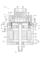
- FIG. 2 is a cross-sectional view of the drive device according to the first embodiment.
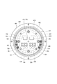
- FIG. 3 is a sectional view taken along line III-III of FIG.
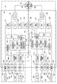
- FIG. 4 is a block diagram showing an ECU according to the first embodiment.
- FIG. 5 is a circuit diagram illustrating a power supply relay according to the first embodiment.
- FIG. 6 is an explanatory diagram illustrating the relationship between the steering torque and the assist torque during driving of the two systems according to the first embodiment.
- FIG. 7 is an explanatory diagram illustrating the relationship between the steering torque and the assist torque in the one-system drive mode according to the first embodiment.
- FIG. 8 is a flowchart illustrating the drive mode selection process according to the first embodiment.
- FIG. 9 is a flowchart illustrating the diagnostic storage process according to the first embodiment.
- FIG. 10 is a time chart for explaining the communication abnormality processing according to the first embodiment.
- FIG. 11 is a time chart for explaining the communication abnormality processing according to the first embodiment.
- FIG. 12 is a time chart for explaining the communication abnormality processing according to the first embodiment.
- FIG. 13 is a time chart for explaining the communication abnormality processing according to the first embodiment.
- FIG. 14 is a flowchart illustrating the drive mode selection process according to the second embodiment.
- FIG. 15 is a time chart for explaining the communication abnormality processing according to the second embodiment.
- FIG. 16 is a time chart for explaining the communication abnormality processing according to the second embodiment.
- FIG. 17 is an explanatory diagram illustrating the relationship between the steering torque and the assist torque according to the reference example.
- FIG. 18 is a time chart illustrating processing at the time of communication abnormality according to a reference example.
- FIGS. 1 to 13 The first embodiment is shown in FIGS. 1 to 13.
- the ECU 10 as a control device is a motor control device that controls the drive of a motor 80 that is a rotary electric machine, and together with the motor 80, serves as a steering device for assisting a steering operation of a vehicle, for example. It is applied to the electric power steering device 8.
- FIG. 1 shows the configuration of a steering system 90 including an electric power steering device 8.
- the steering system 90 includes a steering wheel 91, a steering shaft 92, a pinion gear 96, a rack shaft 97, wheels 98, an electric power steering device 8, and the like, which are steering members.
- the steering wheel 91 is connected to the steering shaft 92.
- the steering shaft 92 is provided with a torque sensor 94 that detects steering torque.
- the torque sensor 94 has a first sensor unit 194 and a second sensor unit 294, and the sensors capable of detecting their own failures are duplicated.
- a pinion gear 96 is provided at the tip of the steering shaft 92.
- the pinion gear 96 meshes with the rack shaft 97.
- a pair of wheels 98 are connected to both ends of the rack shaft 97 via a tie rod or the like.
- the steering shaft 92 connected to the steering wheel 91 rotates.
- the rotational motion of the steering shaft 92 is converted into a linear motion of the rack shaft 97 by the pinion gear 96.
- the pair of wheels 98 are steered at an angle corresponding to the amount of displacement of the rack shaft 97.
- the electric power steering device 8 includes a motor 80, a reduction gear 89 as a power transmission unit that decelerates the rotation of the motor 80 and transmits the rotation to the steering shaft 92, an ECU 10 and the like. That is, the electric power steering device 8 of the present embodiment is a so-called “column assist type", and the steering shaft 92 can be said to be a drive target. It may be a so-called "rack assist type” that transmits the rotation of the motor 80 to the rack shaft 97.
- the motor 80 outputs a part or all of the torque required for steering, and is driven by supplying electric power from batteries 101 and 201 as a power source to decelerate.
- the gear 89 is rotated in the forward and reverse directions.
- the motor 80 is a three-phase brushless motor and has a rotor 860 and a stator 840.
- the motor 80 has a first motor winding 180 and a second motor winding 280.
- the motor windings 180 and 280 have the same electrical characteristics, and are canceled and wound around a common stator 840 with an electric angle of 30 [deg] shifted from each other.
- the motor windings 180 and 280 are controlled so that a phase current whose phase ⁇ is shifted by 30 [deg] is energized.
- the output torque is improved by optimizing the energization phase difference.
- the sixth-order torque ripple can be reduced, and noise and vibration can be reduced.
- heat generation is dispersed and leveled by distributing the current, it is possible to reduce temperature-dependent inter-system errors such as the detected value and torque of each sensor, and increase the amount of current that can be energized. it can.
- the motor windings 180 and 280 may not be canceled and may have different electrical characteristics.
- the combination of the first inverter unit 120 and the first control unit 150 related to the energization control of the first motor winding 180 is combined with the first system L1, the second inverter unit 220 related to the energization control of the second motor winding 280, and the like.
- the combination of the second control unit 250 and the like is referred to as the second system L2.
- the configuration related to the first system L1 is mainly numbered in the 100s
- the configuration related to the second system L2 is mainly numbered in the 200s.
- similar or similar configurations are numbered so that the last two digits are the same.
- first will be described as a subscript "1" and "second” will be described as a subscript "2" as appropriate.
- the drive device 40 is a so-called "mechanical and electrical integrated type" in which the ECU 10 is integrally provided on one side in the axial direction of the motor 80, but the motor 80 and the ECU 10 are separately provided. It may have been.
- the ECU 10 is arranged coaxially with the shaft Ax of the shaft 870 on the side opposite to the output shaft of the motor 80.
- the ECU 10 may be provided on the output shaft side of the motor 80.
- the motor 80 includes a stator 840, a rotor 860, a housing 830 for accommodating these, and the like.
- the stator 840 is fixed to the housing 830, and the motor windings 180 and 280 are wound around the stator 840.
- the rotor 860 is provided inside the stator 840 in the radial direction, and is provided so as to be rotatable relative to the stator 840.
- the shaft 870 is fitted into the rotor 860 and rotates integrally with the rotor 860.
- the shaft 870 is rotatably supported by the housings 830 by bearings 835, 836.
- the end of the shaft 870 on the ECU 10 side projects from the housing 830 toward the ECU 10.
- a magnet 875 is provided at the end of the shaft 870 on the ECU 10 side.
- the housing 830 has a bottomed tubular case 834 including a rear frame end 837 and a front frame end 838 provided on the opening side of the case 834.
- the case 834 and the front frame end 838 are fastened to each other by bolts or the like.
- a lead wire insertion hole 839 is formed in the rear frame end 837. Lead wires 185 and 285 connected to each phase of the motor windings 180 and 280 are inserted into the lead wire insertion holes 839. The lead wires 185 and 285 are taken out from the lead wire insertion holes 839 to the ECU 10 side and connected to the substrate 470.
- the ECU 10 includes a cover 460, a heat sink 465 fixed to the cover 460, a substrate 470 fixed to the heat sink 465, and various electronic components mounted on the substrate 470.
- the cover 460 protects electronic components from external impacts and prevents dust, water, and the like from entering the inside of the ECU 10.
- the cover main body 461 and the connector portions 103 and 203 are integrally formed.
- the connector portions 103 and 203 may be separate from the cover main body 461.
- the terminals 463 of the connector portions 103 and 203 are connected to the substrate 470 via wiring or the like (not shown). The number of connectors and the number of terminals can be appropriately changed according to the number of signals and the like.
- the connector portions 103 and 203 are provided at the axial end of the drive device 40 and open on the side opposite to the motor 80.
- the substrate 470 is, for example, a printed circuit board, and is provided so as to face the rear frame end 837.
- Electronic components for two systems are independently mounted on the board 470 for each system, forming a completely redundant configuration.
- the electronic components are mounted on one substrate 470, but the electronic components may be mounted on a plurality of substrates.
- the surface on the motor 80 side is the motor surface 471
- the surface on the opposite side to the motor 80 is the cover surface 472.
- the switching element 121 constituting the inverter unit 120, the switching element 221 constituting the inverter unit 220, the angle sensor 126, 226, the custom IC 135, 235, and the like are mounted on the motor surface 471.
- the angle sensors 126 and 226 are mounted at locations facing the magnet 875 so that changes in the magnetic field accompanying the rotation of the magnet 875 can be detected.
- Capacitors 128, 228, inductors 129, 229, and microcomputers and the like constituting control units 150 and 250 are mounted on the cover surface 472.
- the microcomputers constituting the control units 150 and 250 are numbered “150” and “250”, respectively.
- Capacitors 128 and 228 smooth the power input from the batteries 101 and 201. Further, the capacitors 128 and 228 assist the power supply to the motor 80 by storing electric charges.
- the capacitors 128 and 228 and the inductors 129 and 229 form a filter circuit to reduce noise transmitted from other devices sharing the battery and reduce noise transmitted from the drive device 40 to other devices sharing the battery.
- the power supply relay 122, 222, the motor relay 125, 225, the current sensor 127, 227, and the like are also mounted on the motor surface 471 or the cover surface 472.
- the ECU 10 includes inverter units 120 and 220, control units 150 and 250, and the like.
- the ECU 10 is provided with connector portions 103 and 203.
- the first connector portion 103 is provided with a first power supply terminal 105, a first ground terminal 106, a first IG terminal 107, a first communication terminal 108, and a first torque terminal 109.
- the first power supply terminal 105 is connected to the first battery 101 via a fuse (not shown).
- the electric power supplied from the positive electrode of the first battery 101 via the first power supply terminal 105 is supplied to the first motor winding 180 via the power supply relay 122, the inverter unit 120, and the motor relay 125. ..
- the first ground terminal 106 is connected to the first ground GND1 which is the ground of the first system inside the ECU 10 and the first external ground GB1 which is the ground of the first system outside the ECU 10.
- the metal body is a common GND plane
- the first external ground GB1 indicates one of the connection points on the GND plane
- the negative electrode of the second battery 201 is also the connection point on this GND plane. Be connected.
- the first IG terminal 107 is connected to the positive electrode of the first battery 101 via a first switch that is on / off controlled in conjunction with a vehicle start switch such as an ignition switch.
- the electric power supplied from the first battery 101 via the first IG terminal 107 is supplied to the first custom IC 135.
- the first custom IC 135 includes a first driver circuit 136, a first circuit power supply 137, a microcomputer monitoring monitor (not shown), a current monitor amplifier (not shown), and the like.
- the first communication terminal 108 is connected to the first vehicle communication circuit 111 and the first vehicle communication network 195.
- the first vehicle communication network 195 and the first control unit 150 are connected to each other so as to be able to transmit and receive via the first vehicle communication circuit 111. Further, the first vehicle communication network 195 and the second control unit 250 are connected so as to be able to receive information, and even if the second control unit 250 fails, the first vehicle communication network 195 including the first control unit 150 is connected. It is configured so that there is no effect.
- the first torque terminal 109 is connected to the first sensor unit 194 of the torque sensor 94.
- the detected value of the first sensor unit 194 is input to the first control unit 150 via the first torque terminal 109 and the first torque sensor input circuit 112.
- the first sensor unit 194 and the first control unit 150 are configured to detect a failure of the torque sensor input circuit system.
- the second connector portion 203 is provided with a second power supply terminal 205, a second ground terminal 206, a second IG terminal 207, a second communication terminal 208, and a second torque terminal 209.
- the second power supply terminal 205 is connected to the positive electrode of the second battery 201 via a fuse (not shown).
- the electric power supplied from the second battery 201 via the second power supply terminal 205 is supplied to the second motor winding 280 via the power supply relay 222, the inverter unit 220, and the motor relay 225.
- the second ground terminal 206 is connected to the second ground GND2, which is the ground of the second system inside the ECU 10, and the second external ground GB2, which is the ground of the second system outside the ECU 10.
- the metal body is a common GND plane
- the second external ground GB2 indicates one of the connection points on the GND plane
- the negative electrode of the second battery 201 is also connected on this GND plane. Connected to the point.
- at least different grids are configured not to connect to the same connection point on the GND plane.
- the second IG terminal 207 is connected to the positive electrode of the second battery 201 via a second switch that is controlled on and off in conjunction with the vehicle start switch.
- the electric power supplied from the second battery 201 via the second IG terminal 207 is supplied to the second custom IC 235.
- the second custom IC 235 includes a second driver circuit 236, a second circuit power supply 237, a microcomputer monitoring monitor (not shown), a current monitor amplifier (not shown), and the like.
- the second communication terminal 208 is connected to the second vehicle communication circuit 211 and the second vehicle communication network 295.
- the second vehicle communication network 295 and the second control unit 250 are connected so as to be able to transmit and receive via the second vehicle communication circuit 211. Further, the second vehicle communication network 295 and the first control unit 150 are connected so as to be able to receive information, and even if the first control unit 150 fails, the second vehicle communication network 295 including the second control unit 250 is affected. It is configured so that there is no.
- the second torque terminal 209 is connected to the second sensor unit 294 of the torque sensor 94.
- the detected value of the second sensor unit 294 is input to the second control unit 250 via the second torque terminal 209 and the second torque sensor input circuit 212.
- the second sensor unit 294 and the second control unit 250 are configured to detect a failure of the torque sensor input circuit system.
- the communication terminals 108 and 208 are connected to separate vehicle communication networks 195 and 295, respectively, but they may be connected to the same vehicle communication network.
- CAN Controller Area Network
- CAN-FD CAN with Flexible Data rate
- FlexRay FlexRay
- the first inverter unit 120 is a three-phase inverter having a switching element 121, and converts the electric power of the first motor winding 180.
- the second inverter unit 220 is a three-phase inverter having a switching element 221 and converts the electric power of the second motor winding 280.
- the first power supply relay 122 is provided between the first power supply terminal 105 and the first inverter unit 120.
- the first motor relay 125 is provided in each phase between the first inverter unit 120 and the first motor winding 180.
- the second power supply relay 222 is provided in each phase between the second power supply terminal 205 and the second inverter unit 220.
- the second motor relay 225 is provided between the second inverter unit 220 and the second motor winding 280.
- the switching elements 121 and 221 and the power supply relays 122 and 222 and the motor relays 125 and 225 are all MOSFETs, but other elements such as IGBTs may be used.
- the first power supply relay 122 is composed of elements having a parasitic diode like a MOSFET
- the two elements 123 and 124 are connected in series so that the directions of the parasitic diodes are opposite to each other. Is desirable.
- the second power supply relay 222 is the same, the illustration is omitted. This makes it possible to prevent the reverse current from flowing when the batteries 101 and 201 are erroneously connected in the opposite directions.
- the power relays 122 and 222 may be mechanical relays.
- the on / off operation of the first switching element 121, the first power supply relay 122, and the first motor relay 125 is controlled by the first control unit 150.
- the on / off operation of the second switching element 221 and the second power supply relay 222 and the second motor relay 225 is controlled by the second control unit 250.
- the first angle sensor 126 detects the rotation angle of the motor 80 and outputs the detected value to the first control unit 150.
- the second angle sensor 226 detects the rotation angle of the motor 80 and outputs the detected value to the second control unit 250.
- the first angle sensor 126 and the first control unit 150, and the second angle sensor 226 and the second control unit 250 are configured to detect failures in their respective angle sensor input circuit systems.
- the first current sensor 127 detects the current applied to each phase of the first motor winding 180.
- the detected value of the first current sensor 127 is amplified by the amplifier circuit in the custom IC 135 and output to the first control unit 150.
- the second current sensor 227 detects the current applied to each phase of the second motor winding 280.
- the detected value of the second current sensor 227 is amplified by the amplifier circuit in the custom IC 235 and output to the second control unit 250.
- the first driver circuit 136 outputs a drive signal for driving the first switching element 121, the first power supply relay 122, and the first motor relay 125 to each element based on the control signal from the first control unit 150.
- the second driver circuit 236 outputs a drive signal for driving the second switching element 221 and the second power supply relay 222 and the second motor relay 225 to each element based on the control signal from the second control unit 250.
- the circuit power supply 137 is connected to the power supply terminal 105 and the IG terminal 107 to supply power to the first control unit 150.
- the circuit power supply 237 is connected to the power supply terminal 205 and the IG terminal 207, and supplies electric power to the second control unit 250.
- the control units 150 and 250 are mainly composed of a microcomputer and the like, and internally include a CPU, ROM, RAM, I / O, etc., which are not shown, and a bus line, etc. connecting these configurations.
- Each process in the control units 150 and 250 may be software processing by executing a program stored in advance in a physical memory device such as a ROM (that is, a readable non-temporary tangible storage medium) on the CPU. However, it may be hardware processing by a dedicated electronic circuit.
- the first control unit 150 and the second control unit 250 are configured to detect their own failures by using, for example, a locked step dual microcomputer or the like.
- the first control unit 150 includes a drive control unit 151, a mode selection unit 152, an abnormality monitoring unit 155, a storage unit 156, and a synchronization processing unit 157.
- the drive control unit 151 controls the energization of the first motor winding 180 by controlling the on / off operation of the first switching element 121. Further, the drive control unit 151 controls the on / off operation of the first power supply relay 122 and the first motor relay 125.
- the second control unit 250 includes a drive control unit 251, a mode selection unit 152, an abnormality monitoring unit 255, a storage unit 256, and a synchronization processing unit 257.
- the drive control unit 251 controls the energization of the second motor winding 280 by controlling the on / off operation of the second switching element 221. Further, the drive control unit 251 controls the on / off operation of the second power supply relay 222 and the second motor relay 225.
- the drive control units 151 and 251 control the drive of the motor 80 by, for example, current feedback control, but the details of the motor control control method may be other than the current feedback control.
- the mode selection units 152 and 252 select the drive mode related to the drive control of the motor 80.
- the drive mode of the present embodiment includes a cooperative drive mode, an independent drive mode, and a single system drive mode, and normally controls the drive of the motor 80 by the cooperative drive mode.
- the normal time is a case where the systems L1 and L2 are normal and two systems can be cooperatively driven, and the control in the cooperative drive mode in the normal time is appropriately referred to as "normal control".
- a case where communication between microcomputers is abnormal or synchronization between systems is not possible is regarded as an incoordination abnormality.
- the determination of incoordination abnormality either communication between microcomputers or synchronization between systems may be omitted.
- the control units 150 and 250 are normal and the communication between the microcomputers is normal, at least one value is shared between the systems, and each system is coordinated to drive the motor 80.
- Control In the present embodiment, the current command value, the current detection value, and the current limit value are shared as control information.
- the first control unit 150 is the master control unit
- the second control unit 250 is the slave control unit
- the current command value calculated by the master first control unit 150 is transmitted to the second control unit 250. Then, the control units 150 and 250 use the same current command value calculated by the first control unit 150.
- the shared current command value may be a value after the current limit or a value before the current limit.
- the current control is performed by the so-called "sum and difference control" that controls the current sum and current difference of the two systems.
- each system independently controls the drive of the motor 80 without using the control information of other systems.
- the one-system drive mode one system is stopped and the drive of the motor 80 is controlled by one system without using the control information of the other system.
- the drive mode in which the motor 80 is driven by one system is referred to as a "single system drive mode".
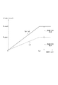
- the assist torque Ta which is the output torque output from the motor 80
- the assist torque Ta is set according to the steering torque Ts.
- the horizontal axis represents the steering torque Ts and the vertical axis represents the assist torque Ta.
- the total output of the two systems is shown by a solid line, and the output of the first system L1 is shown by a broken line.
- the assist torque Ta increases as the steering torque Ts increases in the range where the steering torque Ts reaches the upper limit reaching value Ts2, and the output upper limit in the range where the steering torque Ts reaches the upper limit reaching value Ts2 or more.
- the value is Ta_max2. If the performance and the like of the first system L1 and the second system L2 are the same, the output of the motor 80 is halved by the first system L1 and the second system L2. That is, the output upper limit value Ta_max1 in one system is 1/2 of the output upper limit value Ta_max2 in two systems. Further, the rate of increase of the assist torque Ta with respect to the steering torque Ts in one system is 1/2 of that in the case of driving two systems.
- the assist torque Ta when driving with one system in the independent drive mode, the assist torque Ta is halved when driving with two systems, as shown by the broken line.
- the assist torque Ta increases linearly with the increase of the steering torque Ts in the range up to the output upper limit value Ta_max2, but it may be increased non-linearly.
- Figure 7 shows the output characteristics in the single system drive mode.
- the output when one system is driven by the second system L2 is shown by a solid line, and the total output of the two systems in a normal state is shown by a broken line.
- the single system drive mode when the assist torque Ta with respect to the steering torque Ts is driven by two systems by doubling the rate of increase of the assist torque Ta with respect to the steering torque Ts within the range where the steering torque Ts reaches the upper limit reaching value Ts1. It is the same as.
- the assist torque Ta becomes the output upper limit value Ta_max1 in the one-system drive regardless of the steering torque Ts, and the assist torque Ta becomes smaller than in the two-system drive.
- the output upper limit value Ta_max1 in the one-system drive mode may be increased in the range of the output upper limit value Ta_max2 or less in the two-system drive.
- the one-system drive performed when another system is abnormal is referred to as “backup control” and is also described as “BU control” in the figure.
- BU control changing the output characteristic and increasing the rate of increase of the assist torque Ta with respect to the steering torque Ts and at least one of the output upper limits.
- the abnormality monitoring unit 155 monitors the abnormality of the first system L1 which is its own system. Further, when an abnormality that should stop the own system occurs, the first control unit 150 turns off at least one of the first inverter unit 120, the first power supply relay 122, and the first motor relay 125.
- the abnormality monitoring unit 155 monitors the communication status with the second control unit 250 and the operating status of the second system L2.
- a circuit that stops its own system when an abnormality in the second system L2 is detected as a method for monitoring the operating state of the second system L2 for example, a second inverter unit 220, a second power supply relay 222, and a second motor relay 225.
- at least one of the communication lines related to the communication between the microcomputers is monitored, and it is determined whether or not the emergency stop is performed.
- another system relay monitoring circuit 139 that acquires the second relay gate signal Vrg2 output from the second driver circuit 236 to the second power supply relay 222 is provided, and the second is based on the second relay gate signal Vrg2. Monitor the status of the power relay 222.
- the abnormality monitoring unit 255 monitors the abnormality of the second system L2, which is its own system. Further, when an abnormality that should stop the own system occurs, the second control unit 250 turns off at least one of the second inverter unit 220, the second power supply relay 222, and the second motor relay 225.
- the abnormality monitoring unit 255 monitors the communication status with the first control unit 150 and the operating status of the first system L1.
- a circuit that stops the own system when an abnormality of the first system L1 is detected for example, the first inverter unit 120, the first power supply relay 122, and the first motor relay 125.
- the state of at least one of the communication lines related to the communication between microcomputers, and it is determined whether or not the emergency stop is performed.
- another system relay monitoring circuit 239 that acquires the first relay gate signal Vrg1 output from the first driver circuit 136 to the first power supply relay 122 is provided, and the first is based on the first relay gate signal Vrg1. Monitor the status of the power relay 122.
- the intermediate voltage of the two elements 123 and 124 constituting the power supply relay 122 and the control unit 150 are output.
- the relay drive signal or the post-relay voltage between the power supply relay 122 and the inverter unit 120 may be used. The same applies to the monitoring of the second system L2 in the first control unit 150.
- the information acquired from the other system relay monitoring circuit is “other system relay information”
- the monitoring of the operating status of the other system based on the other system relay information is “other system relay monitoring”
- the monitored relay is “other system relay monitoring”. It is called “other system relay”.
- the state in which the other system relay is turned on is referred to as “other system relay Hi”
- the state in which the other system relay is turned off is referred to as “other system relay Lo”.
- the abnormality monitoring unit 155, 255 determines that the other system is abnormal when a communication abnormality between the microcomputers has occurred and the relay information of the other system is abnormal. Further, in the abnormality monitoring units 155 and 255, when a communication error between microcomputers has occurred and the relay information of another system is normal, the control unit of the other system is normal and a communication error between microcomputers has occurred. Is determined. That is, in the present embodiment, the communication state between microcomputers and the relay monitoring of other systems determine whether the state in which communication is not possible is due to an abnormality in the control unit of the other system or due to an abnormality in communication between microcomputers.
- the storage unit 156 is a non-volatile memory, and stores abnormality information related to the abnormality detected by the abnormality monitoring unit 155.
- the storage unit 256 is a non-volatile memory, and stores abnormality information related to the abnormality detected by the abnormality monitoring unit 255.
- the abnormality information stored in the storage units 156 and 256 includes information related to communication abnormality between microcomputers, information related to other system stoppage, and the like.
- the abnormality information stored in the storage units 156 and 256 is used for abnormality analysis.
- the abnormal information will be referred to as "diag" as appropriate.
- the synchronization processing units 157 and 257 perform synchronization processing for synchronizing the control timings of the control units 150 and 250.
- the first control unit 150 has a clock generation circuit (not shown), and generates a drive timing based on the generated clock signal.
- the synchronization processing unit 157 generates a synchronization signal for synchronizing the drive timing with another system, and transmits the synchronization signal to the second control unit 250.
- the second control unit 250 has a clock generation circuit (not shown) and generates a drive timing based on the generated clock signal.
- the synchronization processing unit 257 corrects the drive timing so that it matches the first system L1 based on the synchronization signal transmitted from the first control unit 150.
- the synchronization signal may be generated outside the control units 150 and 250, and the details of the synchronization process may be different. Further, as the communication line used for transmitting and receiving the synchronization signal, a dedicated communication line may be used, or a signal line used for transmitting and receiving other information may be shared.
- the state in which communication cannot be performed between the control units 150 and 250 may occur not only due to an internal failure of the ECU 10 but also due to an abnormality of the power supply device external to the ECU 10 such as an abnormality of the batteries 101 and 201 and a disconnection of the harness.
- the cooperative drive is performed using the information of other systems acquired by the communication between the microcomputers, it is desirable to promptly switch the drive mode when the communication between the microcomputers is abnormal.
- the abnormality information is stored as a diagnostic at the same time as the drive mode is switched, the abnormality history remains even if it is a temporary abnormality such as a momentary power interruption.
- the output characteristics are changed by backup control, there is a risk of overoutput when the system in which a temporary abnormality has occurred is restored.
- FIG. 17 as a reference example, when one system drive is already performed in the second system L2 and the output due to the independent drive of the first system L1 is added, the steering torque Ts reaches the upper limit. In the range up to the value Ts2, the output becomes excessive from the normal time.
- the output of the two systems in the cooperative drive mode is a broken line
- the output of the second system L2 in the single system drive mode is a two-dot chain line
- the output of the first system L1 in the independent drive mode is a one-dot chain line.
- the output of the two systems in which the output of the second system L2 is added to the output of the first system L1 in the one-system drive mode is shown by a solid line.
- the drive mode is changed when the abnormality is confirmed in the first stage, and diagnostic storage is performed when the abnormality is confirmed in the second stage.
- the time and the abnormality confirmation time of the second stage are different. Specifically, the abnormality confirmation time (for example, 3 [s]) of the second stage is made longer than the abnormality confirmation time (for example, several [ms]) of the first stage. It is preferable that the abnormality confirmation time of the first stage is as short as possible, and the abnormality confirmation time of the second stage is set according to the time required for restarting by resetting the microcomputer of another system. In detail, it is set to a time longer than the time required for restarting by the amount of time allowed as a power interruption. In addition, when another system has already shifted to backup control, overoutput is prevented by stopping the assist of the own system. Further, in the present embodiment, the time until the other system stop confirmation determination is made is equal to the abnormality confirmation time of the second stage.
- step S101 The drive mode selection process of the present embodiment will be described with reference to the flowchart of FIG. This process is executed by the control units 150 and 250 at a predetermined cycle.
- step S101 the “step” in step S101 is omitted and simply referred to as the symbol “S”. The same applies to the other steps.
- control units 150 and 250 determine whether or not the communication between the microcomputers is abnormal. If it is determined that the communication between the microcomputers is abnormal (S101: YES), the process proceeds to S107. When it is determined that the communication between the microcomputers is normal (S101: NO), the process proceeds to S102. If the communication between the microcomputers is normally determined and the counters Ct1, Ct2, and Ct3 described later are counted, the data is reset.
- control units 150 and 250 determine whether or not cooperative driving is in progress. When it is determined that the cooperative drive is in progress (S102: YES), the process proceeds to S103 and the cooperative drive is continued. If it is determined that the cooperative drive is not in progress (S102: NO), the process proceeds to S104.
- control units 150 and 250 determine whether or not another system has shifted to backup control. When it is determined that the other system has shifted to backup control (S104: YES), the shift to S105 is performed, and the drive mode is set to assist stop. If it is determined that the other system has not shifted to backup control (S104: NO), the system shifts to S106 and the drive mode of the own system is set to the independent drive mode.
- the control units 150 and 250 determine whether or not the first-stage communication abnormality counter Ct1 is larger than the first-stage confirmation determination value TH1.
- the first-stage confirmation determination value TH1 is set according to the first-stage abnormality confirmation time. When it is determined that the first-stage communication abnormality counter Ct1 is equal to or less than the first-stage confirmation determination value TH1 (S109: NO), the process of S110 is not performed and this routine is terminated. When it is determined that the first-stage abnormality confirmation counter Ct1 is larger than the first-stage confirmation determination value TH1 (S109: YES), the process proceeds to S110, the first-stage communication abnormality is confirmed, and the drive mode is set to independent drive. For example, the first-stage confirmation determination value TH1 may be set to 0, and the mode may be shifted to the independent drive mode immediately after the communication abnormality between the microcomputers is detected.
- the control units 150 and 250 determine whether or not the other system relay is Lo. When it is determined that the other system relay is Hi (S111: NO), this routine is terminated without performing the processing after S113. If the other system monitoring counter Ct3 is counted, it is reset. When it is determined that the other system relay is Lo (S111: YES), the process proceeds to S112 and the other system monitoring counter Ct3 is incremented.
- the control units 150 and 250 determine whether or not the other system monitoring counter Ct3 is larger than the other system abnormality confirmation determination value TH3.
- the other system abnormality confirmation determination value TH3 is set according to the time for shifting from the independent drive to the backup control.
- the processing of S114 is not performed and this routine is terminated.
- the process shifts to S114 and shifts to backup control. Further, the other system stop is stored in the storage units 156 and 256 as a diagnosis.
- the diagnostic storage process of this embodiment will be described with reference to the flowchart of FIG. This process is executed by the control units 150 and 250 at a predetermined cycle.
- the control units 150 and 250 determine whether or not the communication between the microcomputers is abnormal. When it is determined that the communication between the microcomputers is normal (S151: NO), the processing after S152 is not performed. If the second-stage abnormality confirmation counter Ct2, which will be described later, is counted, it is reset. When it is determined that the communication between the microcomputers is abnormal (S151: YES), the process proceeds to S152.
- control units 150 and 250 determine whether or not the communication abnormality in the first stage is confirmed. If it is determined that the communication abnormality in the first stage has not been confirmed (S152: NO), the processing after S152 is not performed, and this routine is terminated. When it is determined that the communication abnormality in the first stage is confirmed (S152: YES), the process proceeds to S153.
- control units 150 and 250 determine whether or not the own system is in backup control. If it is determined that the own system is in backup control (S153: YES), this routine is terminated without performing the processing after S154. If it is determined that the own system is not in backup control (S153: NO), the process proceeds to S154.
- the control units 150 and 250 determine whether or not the power latch is in progress. Even after the start switch is turned off, the control units 150 and 250 continue to be on and perform end processing and the like, and turn off after the end process is completed. In the present embodiment, the state in which the control units 150 and 250 are turned on after the start switch is turned off is defined as "power latching". If it is determined that the power latch is in progress (S154: YES), the processing after S155 is not performed, and this routine is terminated. If it is determined that the power latch is not in progress (S154: NO), the process proceeds to S155.
- control units 150 and 250 determine whether or not the other system relay is Lo. If it is determined that the other system relay is Lo (S155: YES), the processing after S156 is not performed, and this routine is terminated. When it is determined that the other system relay is Hi (S155: NO), the process proceeds to S156.
- the control units 150 and 250 increment the second-stage communication abnormality counter Ct2.
- the second-stage confirmation determination value TH2 is set according to the second-stage abnormality confirmation time, and is set to the same value as the other system abnormality confirmation determination value TH3.
- the process of S158 is not performed and this routine is terminated.
- the process proceeds to S158 to confirm the second-stage communication abnormality, and the communication abnormality between the microcomputers is stored as a diagnostic. Store in units 156 and 256.
- S153 to S155 correspond to the diagnostic storage mask condition determination, and when the positive determination is made in S153, the other system stop has already been confirmed, so that the diagnostic storage mask condition related to the communication abnormality between the microcomputers is set. It is determined that it is established. If an affirmative judgment is made in S155, it is determined that the other system relay is Lo, communication is not possible due to the other system stop instead of communication between microcomputers, and the diagnostic storage mask condition related to the communication abnormality between microcomputers is satisfied. .. Further, when the affirmative judgment is made in S154, it is determined that the diagnostic storage mask condition related to the communication abnormality between the microcomputers is satisfied because the power latch is in progress and the IG is normally turned off. If a negative determination is made in S153 to S155, it is determined that the diagnostic storage mask condition is not satisfied. The order of S153 to S155 may be changed, or some processes may be omitted.
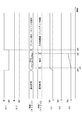
- the processing at the time of communication abnormality will be described based on the time charts of FIGS. 10 to 13.
- the power supply state to the first control unit 150 (described as “IG-1” in the figure), the power supply state to the second control unit 250 (described as “IG-2” in the figure), and the first
- the drive mode of the first system L1 is the drive mode of the second system L2, the first stage communication abnormality counter Ct1, the second stage communication abnormality counter Ct2, and the other system monitoring counter Ct3.
- the counters Ct1, Ct2, and Ct3 will be values in the second control unit 250.
- the state in which power is supplied to the control units 150 and 250 is referred to as "power on”
- the state in which power supply is interrupted is referred to as "power off”. 11 to 14 and 18 are substantially the same.
- one counter is used to simultaneously perform abnormal case treatment and diagnostic memory.
- the microcomputer of the first control unit 150 is stopped.
- the second control unit 250 detects the communication abnormality between the microcomputers and starts counting the abnormality counter.
- the second control unit 250 determines that the first system L1 which is the partner system has stopped, and stores the abnormality information of the partner system stop as a diagnosis. At the same time, shift from normal control to backup control.
- the abnormality that occurred at time x90 is a momentary power interruption
- the microcomputer of the first control unit 150 is restarted at time x92.
- the first control unit 150 after restarting drives the motor 80 in the cooperative drive mode or the independent drive mode.
- the diagnosis of the other system stop is stored, so that there is a possibility that unnecessary measures such as repair or replacement of the first control unit 150 may be performed.
- the abnormality confirmation related to the change of the drive mode and the abnormality confirmation related to the diagnostic memory are separated, and a two-stage confirmation is performed in which different confirmation times are set. Further, the transition from the independent drive mode to the backup control is based on the information of monitoring other systems, and the drive mode is switched and the diagnosis is stored by using a total of three counters.
- the microcomputer of the first control unit 150 when the power supply of the first system L1 is momentarily interrupted at time x10, the microcomputer of the first control unit 150 is stopped.
- the second control unit 250 detects a communication abnormality between microcomputers and starts counting the first-stage communication abnormality counter Ct1.
- the first-stage communication abnormality counter Ct1 exceeds the first-stage confirmation determination value TH1 at time x11, the second control unit 250 switches the drive mode to the independent drive mode. In the independent drive mode, the output characteristics are not changed, so that when the first system L1 is stopped, the output is halved from the normal state.
- the microcomputer of the first control unit 150 while the microcomputer of the first control unit 150 is restarting, the other system relay becomes Lo, so the counting of the other system monitoring counter Ct3 is started. At this time, since the other system relay is Lo and the diagnostic storage mask condition is satisfied, the second-stage communication abnormality counter Ct2 is not counted.
- the other system relay becomes Hi, so the other system monitoring counter Ct3 is reset.
- the first control unit 150 acquires the information that the second system L2 is in the independent drive mode by the communication between the microcomputers, the first control unit 150 performs the drive control of the motor 80 in the independent drive mode.
- the temporary stop and restart of the first control unit 150 due to a momentary power interruption or the like is left in the storage unit 256 of the second control unit 250 with an erroneous diagnosis that the first control unit 150 is abnormal. Can be prevented.
- the drive control of the motor 80 in the two systems is performed in the independent drive mode, so that it is possible to prevent an output decrease and an overoutput.
- FIG. 11 is an example in which the power supply of the first system L1 is turned off at time x20 and the off state is continued.
- the processing of the time x20 and the time x21 is the same as the processing of the time x10 and the time x11 in FIG.
- Lo of the other system relay is continued.
- the other system monitoring counter Ct3 exceeds the other system abnormality confirmation determination value TH3 at the time x22
- the second control unit 250 stores the other system stop as a diagnosis in the storage unit 256.
- the drive mode is switched from the independent drive mode to the single system drive mode, the backup control is shifted, and the output characteristics are changed.
- FIG. 12 is an example when a communication error between microcomputers occurs at time x30.
- the power supply is on for both the systems L1 and L2, and the counters Ct1, Ct2, and Ct3 have the same values in the control units 150 and 250.
- the count of the first-stage communication error counter Ct1 is started.
- the first-stage communication abnormality counter Ct1 exceeds the first-stage confirmation determination value TH1 at time x31, both the systems L1 and L2 shift to the independent drive mode.
- the control units 150 and 250 store the inter-microcomputer communication abnormality as a diagnosis in their own storage units 156 and 256, respectively. For example, considering that the information stored in the storage units 156 and 256 is used for failure analysis and the like, there is no actual harm even if the diagnostic storage timing is delayed from the switching of the drive mode.
- FIG. 13 is an example in which the power supply of the first system L1 is restored after the backup control shift.
- the processing of time x40 to time x42 is the same as the processing of time x20 to time x22 in FIG.
- the first control unit 150 is activated.
- the first control unit 150 acquires the information that the second system L2 has been shifted to the backup control by inter-microcomputer communication
- the first control unit 150 drives the motor 80 by the first system L1 so as not to cause excessive assist.
- the assist is stopped without any control. Since the microcomputer of the first control unit 150 is operating, processing other than drive control of the motor 80, such as abnormality monitoring, may be performed. Further, in this case, the other system is stopped for a relatively long time, and the other system stop remains as a diagnosis.
- control units 150 and 250 of the ECU 10 of the present embodiment include drive control units 151 and 251, an abnormality monitoring unit 155 and 255, and a storage unit 156 and 256.
- the drive control units 151 and 251 control the operation of the motor 80 to be controlled.
- the abnormality monitoring units 155 and 255 perform abnormality monitoring.
- the storage units 156 and 256 store abnormality information according to the abnormality monitoring result.
- a timer related to the abnormality determination determination and a timer related to the abnormality memory confirmation determination are separately provided, and the timing of the abnormality determination determination and the timing of the abnormality memory confirmation are different and monitored.
- the time from the detection of the target abnormality to the determination of the abnormal memory confirmation is longer than the time from the detection of the monitored abnormality to the determination of the determination of the treatment at the time of abnormality. As a result, the probability that an erroneous abnormality history is stored can be reduced.
- the ECU 10 is provided with a plurality of control units 150 and 250 having drive control units 151 and 251, abnormality monitoring units 155 and 255, and storage units 156 and 256.
- the monitored abnormality of the present embodiment is a communication abnormality or a synchronization abnormality between the control units 150 and 250, which is an incoordination abnormality.
- the time from the detection of the incoordination abnormality to the determination of the abnormal memory confirmation is set according to the time required for restarting the control units 150 and 250. As a result, a temporary abnormality due to an external factor such as a momentary power interruption is not stored, so that the probability that an erroneous abnormality history is stored can be reduced.
- the control units 150 and 250 mask the abnormal memory confirmation determination when the other control units are stopped. Specifically, when another control unit is stopped, the time of the abnormality determination time in the second stage is not measured, and the abnormality information related to the incoordination abnormality is not stored. As a result, it is possible to avoid erroneously memorizing a state in which coordination is not possible due to other system stoppage or normal IG off as an incoordination abnormality.
- the control units 150 and 250 can monitor the control status of the motor 80 by another control unit based on other system relay information acquired separately from the communication between the control units 150 and 250 to be monitored. Further, when an incoordination abnormality has occurred and the other system stop is confirmed based on the other system relay information, the control units 150 and 250 use the information related to the other system stop as the abnormality information and their own storage units 156. Store in 256. As a result, information related to the shutdown of other systems can be appropriately stored.
- the time from the detection of the incoordination abnormality to the determination of other system stop confirmation is longer than the time from the detection of the incoordination abnormality to the determination of the treatment confirmation at the time of abnormality. As a result, the probability that an erroneous abnormality history is stored can be reduced. Further, the time from the detection of the incoordination abnormality to the determination of stopping the other system is set according to the time required for restarting the control units 150 and 250. As a result, a temporary abnormality due to an external factor such as a momentary power interruption is not stored, so that the probability that an erroneous abnormality history is stored can be reduced.
- the control units 150 and 250 shift to backup control different from the emergency treatment.
- the abnormal action of the present embodiment is a shift to the independent drive mode, and does not shift to the backup control until it is determined that the other system is stopped. Further, the control units 150 and 250 maintain the stopped state of the own system when the other system shifts to the backup control at the time of its own activation. As a result, it is possible to avoid inconsistency in control when returning from the temporary stop state.
- the output characteristics are changed so as to supplement the output of other systems.
- the independent drive mode in which the output characteristics are not changed without shifting to the backup control until the other system stop confirmation judgment is made, it is possible to prevent overoutput when the other system recovers from the temporary stop.
- overoutput can be prevented by maintaining the stopped state of the own system.
- the second embodiment is shown in FIGS. 14 to 16.
- the drive mode selection process is different from the above-described embodiment, and this point will be mainly described.
- the cooperative drive mode is restored.
- the drive mode selection process of the present embodiment will be described with reference to the flowchart of FIG.
- the processing of S201 and S202 is the same as the processing of S101 and S102 in FIG. If the communication between the microcomputers is abnormal, the process proceeds to S206. Further, when the communication between the microcomputers is normal and the cooperative drive is in progress, the process shifts to S204 to continue the cooperative drive, and when the cooperative drive is not in progress, the process shifts to S203.
- control units 150 and 250 determine whether or not the cooperative return condition is satisfied. When it is determined that the cooperative return condition is satisfied (S203: YES), the process proceeds to S204 and the drive mode is switched to the cooperative drive mode. When it is determined that the cooperative return condition is not satisfied (S203: NO), the process proceeds to S205 and the drive mode is set to the independent drive mode.
- the processing of S206 to S213 is the same as the processing of S107 to S114 in FIG.
- the command deviation ⁇ I * which is the absolute value of the difference between the first current command value calculated by the first control unit 150 and the second current command value calculated by the second control unit 250, deviates. If it is determined that it is smaller than the determination value ⁇ I_th, it is considered that there is no command deviation between the systems, and it is determined that cooperative return is possible. Further, when the first current limit value Ilim1 calculated by the first control unit 150 and the second current limit value Ilim2 calculated by the second control unit 250 are both larger than the return determination value, it is determined that cooperative return is possible. To do. Further, when the steering torque Ts is smaller than the non-steering determination value Ts_th, it is determined that the cooperative return is possible. Furthermore, when the vehicle speed V is smaller than the vehicle speed determination value V_th, it is determined that cooperative return is possible.
- the command deviation ⁇ I * is smaller than the deviation determination value ⁇ I_th
- the current limit values Illim1 and Ilim2 are larger than the return determination value
- the steering torque Ts is smaller than the non-steering determination value Ts_th
- the vehicle speed V is the vehicle speed determination. If it is smaller than the value V_th, it is determined that "the cooperative return condition is satisfied".
- the communication between the microcomputers returns to normal after the communication abnormality between the microcomputers occurs, it is considered that the "incoordination abnormality has been resolved".
- FIG. 15 is an example in the case where a momentary power interruption occurs as in FIG. 10, and the processing of time x50 to time x52 is the same as the processing of time x10 to time x12 in FIG.
- both the systems L1 and L2 switch the drive mode from the independent drive mode to the cooperative drive mode and return to the normal control.
- FIG. 16 is an example in which the power supply of the first system L1 is restored after the backup control shift as in FIG.
- the processing of time x60 to time x62 is the same as the processing of time x40 to time x42 in FIG.
- both the systems L1 and L2 are set to the independent drive mode.
- both the systems L1 and L2 switch the drive mode from the independent drive mode to the cooperative drive mode and return to the normal control.
- the period during which the power supply is stopped is longer than the other system abnormality confirmation time corresponding to the other system abnormality confirmation determination value TH3, the diagnosis of the other system stop remains.
- control units 150 and 250 return to the normal control when the incoordination abnormality is resolved and the cooperative return condition is satisfied.
- the control units 150 and 250 return to the normal control when the incoordination abnormality is resolved and the cooperative return condition is satisfied.
- the control units 150 and 250 return to the normal control when the incoordination abnormality is resolved and the cooperative return condition is satisfied.
- the ECU 10 is a "control device”
- the motor 80 is a "control target”
- the drive control units 151 and 251 are “operation control units”
- the communication abnormality between microcomputers is “communication abnormality between control units”
- other system relays The information corresponds to "other system monitoring information”
- restarting by resetting the microcomputer corresponds to "restarting the control unit”.
- the monitored abnormality is an uncoordinated abnormality
- the uncoordinated abnormality includes an inter-microcomputer communication abnormality and a synchronization abnormality.
- either the communication abnormality between the microcomputers or the synchronization abnormality may be regarded as an incoordination abnormality.
- the monitored abnormality may be an abnormality other than the incoordination abnormality.
- the other system monitoring information is the other system relay information.
- the other system monitoring information may use information other than the other system relay information capable of monitoring the state of the other system.
- the relay information of the other system is directly acquired by using the monitoring circuit of the other system.
- the other system monitoring information may be acquired by a communication separate from the communication for communicating the shared control information.
- the determination timing is different, so that the abnormality determination determination and the abnormal memory confirmation determination are different.
- the determination condition other than the determination timing may be different so that the abnormality treatment confirmation determination and the abnormality memory confirmation determination may be different.
- the emergency treatment is a shift to the independent drive mode.
- the emergency treatment may be a treatment other than the transition to the independent drive mode.
- the abnormality confirmation time of the second stage and the other system stop confirmation determination time are equal. In other embodiments, the abnormality confirmation time of the second stage and the other system stop confirmation determination time may be different.
- the steering state was determined based on the steering torque.
- the steering state may be determined based on the steering wheel speed, the motor speed, or the rack speed, not limited to the steering torque.
- the steering state may be determined based on the current command value and the current detection value.
- the current command value When the value of the current command value is large, it is highly probable that the vehicle is being steered. Therefore, when the current command value is larger than the determination threshold value, or when the current command value is smaller than the determination threshold value, it is determined that the vehicle is in a non-steering state. The same applies to the current detection value.
- the steering state may be determined using two or more of the steering torque, the steering wheel speed, the motor speed, the rack speed, the current command value and the current detection value.
- the command deviation, the current limit value, the steering torque, and the vehicle speed are used as the cooperative return determination conditions.
- the cooperative return determination condition a part of the above four determination conditions illustrated may be omitted, or another determination condition may be added, for example, an item related to the behavior of the vehicle. Other items such as lateral G of the vehicle and yaw rate may be added.
- the current command value, the current detection value, and the current limit value are shared between the systems in the cooperative drive mode. In other embodiments, the current limit value may not be shared in the coordinated drive mode.
- the first control unit 150 is the master control unit
- the second control unit 250 is the slave control unit
- the current command values calculated by the first control unit 150 are the control units 150 and 250. Used in.
- the current command value is not shared, and the current command value of the own system may be used even in the cooperative drive mode. Further, values other than the current command value, the current detection value, and the current limit value may be shared.
- two motor windings, two inverter units and two control units are provided.
- the motor windings may be one or more.
- the number of inverter units and control units may be one or three or more.
- one control unit is provided for a plurality of motor windings and an inverter unit, or a plurality of inverter units and a motor winding are provided for one control unit, and so on.
- the number of units and the number of control units may be different.
- a power supply is provided for each system and the ground is separated.
- one power source may be shared by a plurality of systems.
- a plurality of systems may be connected to a common ground.
- the rotary electric machine is a three-phase brushless motor. In other embodiments, the rotary electric machine is not limited to a brushless motor. Further, it may be a so-called motor generator that also has a function of a generator.
- the control device is applied to an electric power steering device. In another embodiment, the control device may be applied to a steering device other than the electric power steering device that controls steering, such as a steer-by-wire device. Further, it may be applied to an in-vehicle device other than the steering device or a device other than the in-vehicle device.
- the controls and methods thereof described in the present disclosure are realized by a dedicated computer provided by configuring a processor and memory programmed to perform one or more functions embodied by a computer program. May be done.
- the controls and methods thereof described in the present disclosure may be implemented by a dedicated computer provided by configuring the processor with one or more dedicated hardware logic circuits.
- the control unit and method thereof described in the present disclosure may be a combination of a processor and memory programmed to perform one or more functions and a processor composed of one or more hardware logic circuits. It may be realized by one or more dedicated computers configured.
- the computer program may also be stored in a computer-readable non-transitional tangible storage medium as an instruction executed by the computer. As described above, the present disclosure is not limited to the above-described embodiment, and can be implemented in various forms without departing from the spirit thereof.
Landscapes
- Engineering & Computer Science (AREA)
- Power Engineering (AREA)
- Physics & Mathematics (AREA)
- General Physics & Mathematics (AREA)
- Power Steering Mechanism (AREA)
- Control Of Electric Motors In General (AREA)
Abstract
A control device (10), provided with operation control units (151, 251), abnormality monitoring units (155, 255), and storage units (156, 256). The operation control units (151, 251) control the operation of a control object (80). The abnormality monitoring units (155, 255) perform abnormality monitoring. The storage units (156, 256) store abnormality information corresponding to an abnormality monitoring result. An abnormality measure confirmation determination relating to determining of a transition to an abnormality measure due to the occurence of an abnormality, and an abnormality storage confirmation determination for storing a monitoring object abnormality as abnormality information, when the monitoring object abnormality is detected, are different.
Description
本出願は、2019年8月15日に出願された特許出願番号2019-149071号に基づくものであり、ここにその記載内容を援用する。
This application is based on Patent Application No. 2019-149071 filed on August 15, 2019, and the contents of the description are incorporated herein by reference.
本開示は、制御装置に関する。
This disclosure relates to a control device.
従来、複数の制御部にてモータの駆動を制御する回転電機制御装置が知られている。例えば特許文献1では、2つの制御部が設けられており、1つのマスター制御部にて演算される指令値をスレーブ制御部に送信することで、2系統を協調動作させている。また、マイコン間通信異常が生じた場合、独立駆動制御に移行する。
Conventionally, a rotary electric machine control device that controls the drive of a motor by a plurality of control units has been known. For example, in Patent Document 1, two control units are provided, and two systems are operated in cooperation by transmitting a command value calculated by one master control unit to a slave control unit. In addition, when a communication error between microcomputers occurs, the control shifts to independent drive control.
ところで、マイコン間通信異常等の装置の異常動作は、装置内部の異常に限らず、電源からの電力供給の異常によっても生じる場合がある。ここで、外部要因の電源瞬断等の異常が履歴として記憶されると、不要な修理や交換を行う虞がある。本開示の目的は、異常状態を適切に記憶可能な制御装置を提供することにある。
By the way, abnormal operation of the device such as communication error between microcomputers may occur not only due to an abnormality inside the device but also due to an abnormality in the power supply from the power supply. Here, if an abnormality such as a power supply momentary interruption due to an external factor is stored as a history, there is a risk of unnecessary repair or replacement. An object of the present disclosure is to provide a control device capable of appropriately storing an abnormal state.
本開示の制御装置は、動作制御部と、異常監視部と、記憶部と、を備える。動作制御部は、制御対象の動作を制御する。異常監視部は、異常監視を行う。記憶部には、異常監視結果に応じた異常情報が記憶される。監視対象異常が検出された場合、異常発生に伴う異常時処置への移行判定に係る異常時処置確定判定と、異常情報として監視対象異常を記憶させる異常記憶確定判定と、が異なっている。これにより、監視対象異常を適切に記憶させることができる。
The control device of the present disclosure includes an operation control unit, an abnormality monitoring unit, and a storage unit. The motion control unit controls the motion of the controlled object. The abnormality monitoring unit monitors the abnormality. Abnormal information according to the abnormality monitoring result is stored in the storage unit. When an abnormality to be monitored is detected, the determination of the action to be confirmed at the time of abnormality related to the determination of transition to the action to be taken at the time of abnormality due to the occurrence of the abnormality and the determination of the confirmation of abnormal memory to store the abnormality to be monitored as abnormality information are different. As a result, the monitored abnormality can be appropriately stored.
本開示についての上記目的及びその他の目的、特徴や利点は、添付の図面を参照しながら下記の詳細な記述により、より明確になる。その図面は、
図1は、第1実施形態によるステアリングシステムの概略構成図であり、
図2は、第1実施形態による駆動装置の断面図であり、
図3は、図2のIII-III線断面図であり、
図4は、第1実施形態によるECUを示すブロック図であり、
図5は、第1実施形態による電源リレーを説明する回路図であり、
図6は、第1実施形態による2系統駆動時の操舵トルクとアシストトルクとの関係を説明する説明図であり、
図7は、第1実施形態による片系統駆動モードでの操舵トルクとアシストトルクとの関係を説明する説明図であり、
図8は、第1実施形態による駆動モード選択処理を説明するフローチャートであり、
図9は、第1実施形態によるダイアグ記憶処理を説明するフローチャートであり、
図10は、第1実施形態による通信異常時処理を説明するタイムチャートであり、
図11は、第1実施形態による通信異常時処理を説明するタイムチャートであり、
図12は、第1実施形態による通信異常時処理を説明するタイムチャートであり、
図13は、第1実施形態による通信異常時処理を説明するタイムチャートであり、
図14は、第2実施形態による駆動モード選択処理を説明するフローチャートであり、
図15は、第2実施形態による通信異常時処理を説明するタイムチャートであり、
図16は、第2実施形態による通信異常時処理を説明するタイムチャートであり、
図17は、参考例による操舵トルクとアシストトルクとの関係を説明する説明図であり、
図18は、参考例による通信異常時処理を説明するタイムチャートである。
The above objectives and other objectives, features and advantages of the present disclosure will be clarified by the following detailed description with reference to the accompanying drawings. The drawing is
FIG. 1 is a schematic configuration diagram of a steering system according to the first embodiment. FIG. 2 is a cross-sectional view of the drive device according to the first embodiment. FIG. 3 is a sectional view taken along line III-III of FIG. FIG. 4 is a block diagram showing an ECU according to the first embodiment. FIG. 5 is a circuit diagram illustrating a power supply relay according to the first embodiment. FIG. 6 is an explanatory diagram illustrating the relationship between the steering torque and the assist torque during driving of the two systems according to the first embodiment. FIG. 7 is an explanatory diagram illustrating the relationship between the steering torque and the assist torque in the one-system drive mode according to the first embodiment. FIG. 8 is a flowchart illustrating the drive mode selection process according to the first embodiment. FIG. 9 is a flowchart illustrating the diagnostic storage process according to the first embodiment. FIG. 10 is a time chart for explaining the communication abnormality processing according to the first embodiment. FIG. 11 is a time chart for explaining the communication abnormality processing according to the first embodiment. FIG. 12 is a time chart for explaining the communication abnormality processing according to the first embodiment. FIG. 13 is a time chart for explaining the communication abnormality processing according to the first embodiment. FIG. 14 is a flowchart illustrating the drive mode selection process according to the second embodiment. FIG. 15 is a time chart for explaining the communication abnormality processing according to the second embodiment. FIG. 16 is a time chart for explaining the communication abnormality processing according to the second embodiment. FIG. 17 is an explanatory diagram illustrating the relationship between the steering torque and the assist torque according to the reference example. FIG. 18 is a time chart illustrating processing at the time of communication abnormality according to a reference example.
以下、本開示による制御装置を図面に基づいて説明する。以下、複数の実施形態において、実質的に同一の構成には同一の符号を付して説明を省略する。
Hereinafter, the control device according to the present disclosure will be described with reference to the drawings. Hereinafter, in a plurality of embodiments, substantially the same configuration will be designated by the same reference numerals and description thereof will be omitted.
(第1実施形態)
第1実施形態を図1~図13に示す。図1に示すように、制御装置としてのECU10は、回転電機であるモータ80の駆動を制御するモータ制御装置であって、モータ80とともに、例えば車両のステアリング操作を補助するための操舵装置としての電動パワーステアリング装置8に適用される。図1は、電動パワーステアリング装置8を備えるステアリングシステム90の構成を示す。ステアリングシステム90は、操舵部材であるステアリングホイール91、ステアリングシャフト92、ピニオンギア96、ラック軸97、車輪98、および、電動パワーステアリング装置8等を備える。 (First Embodiment)
The first embodiment is shown in FIGS. 1 to 13. As shown in FIG. 1, theECU 10 as a control device is a motor control device that controls the drive of a motor 80 that is a rotary electric machine, and together with the motor 80, serves as a steering device for assisting a steering operation of a vehicle, for example. It is applied to the electric power steering device 8. FIG. 1 shows the configuration of a steering system 90 including an electric power steering device 8. The steering system 90 includes a steering wheel 91, a steering shaft 92, a pinion gear 96, a rack shaft 97, wheels 98, an electric power steering device 8, and the like, which are steering members.
第1実施形態を図1~図13に示す。図1に示すように、制御装置としてのECU10は、回転電機であるモータ80の駆動を制御するモータ制御装置であって、モータ80とともに、例えば車両のステアリング操作を補助するための操舵装置としての電動パワーステアリング装置8に適用される。図1は、電動パワーステアリング装置8を備えるステアリングシステム90の構成を示す。ステアリングシステム90は、操舵部材であるステアリングホイール91、ステアリングシャフト92、ピニオンギア96、ラック軸97、車輪98、および、電動パワーステアリング装置8等を備える。 (First Embodiment)
The first embodiment is shown in FIGS. 1 to 13. As shown in FIG. 1, the
ステアリングホイール91は、ステアリングシャフト92と接続される。ステアリングシャフト92には、操舵トルクを検出するトルクセンサ94が設けられる。トルクセンサ94は、第1センサ部194および第2センサ部294を有しており、各々自身の故障検出ができるセンサが二重化されている。ステアリングシャフト92の先端には、ピニオンギア96が設けられる。ピニオンギア96は、ラック軸97に噛み合っている。ラック軸97の両端には、タイロッド等を介して一対の車輪98が連結される。
The steering wheel 91 is connected to the steering shaft 92. The steering shaft 92 is provided with a torque sensor 94 that detects steering torque. The torque sensor 94 has a first sensor unit 194 and a second sensor unit 294, and the sensors capable of detecting their own failures are duplicated. A pinion gear 96 is provided at the tip of the steering shaft 92. The pinion gear 96 meshes with the rack shaft 97. A pair of wheels 98 are connected to both ends of the rack shaft 97 via a tie rod or the like.
運転者がステアリングホイール91を回転させると、ステアリングホイール91に接続されたステアリングシャフト92が回転する。ステアリングシャフト92の回転運動は、ピニオンギア96によってラック軸97の直線運動に変換される。一対の車輪98は、ラック軸97の変位量に応じた角度に操舵される。
When the driver rotates the steering wheel 91, the steering shaft 92 connected to the steering wheel 91 rotates. The rotational motion of the steering shaft 92 is converted into a linear motion of the rack shaft 97 by the pinion gear 96. The pair of wheels 98 are steered at an angle corresponding to the amount of displacement of the rack shaft 97.
電動パワーステアリング装置8は、モータ80、モータ80の回転を減速してステアリングシャフト92に伝える動力伝達部としての減速ギア89、および、ECU10等を備える。すなわち、本実施形態の電動パワーステアリング装置8は、所謂「コラムアシストタイプ」であり、ステアリングシャフト92が駆動対象といえる。モータ80の回転をラック軸97に伝える所謂「ラックアシストタイプ」等としてもよい。
The electric power steering device 8 includes a motor 80, a reduction gear 89 as a power transmission unit that decelerates the rotation of the motor 80 and transmits the rotation to the steering shaft 92, an ECU 10 and the like. That is, the electric power steering device 8 of the present embodiment is a so-called "column assist type", and the steering shaft 92 can be said to be a drive target. It may be a so-called "rack assist type" that transmits the rotation of the motor 80 to the rack shaft 97.
図1~図4に示すように、モータ80は、操舵に要するトルクの一部または全部を出力するものであって、電源としてのバッテリ101、201から電力が供給されることにより駆動され、減速ギア89を正逆回転させる。モータ80は、3相ブラシレスモータであって、ロータ860およびステータ840を有する。
As shown in FIGS. 1 to 4, the motor 80 outputs a part or all of the torque required for steering, and is driven by supplying electric power from batteries 101 and 201 as a power source to decelerate. The gear 89 is rotated in the forward and reverse directions. The motor 80 is a three-phase brushless motor and has a rotor 860 and a stator 840.
モータ80は、第1モータ巻線180および第2モータ巻線280を有する。モータ巻線180、280は電気的特性が同等であり、共通のステータ840に、互いに電気角30[deg]ずらしてキャンセル巻きされる。これに応じて、モータ巻線180、280には、位相φが30[deg]ずれた相電流が通電されるように制御される。通電位相差を最適化することで、出力トルクが向上する。また、6次のトルクリプルを低減することができ、騒音、振動の低減することができる。また、電流も分散されることで発熱が分散、平準化されるため、各センサの検出値やトルク等、温度依存の系統間誤差を低減可能であるとともに、通電可能な電流量を増やすことができる。なお、モータ巻線180、280は、キャンセル巻きされていなくてもよく、電気的特性が異なっていてもよい。
The motor 80 has a first motor winding 180 and a second motor winding 280. The motor windings 180 and 280 have the same electrical characteristics, and are canceled and wound around a common stator 840 with an electric angle of 30 [deg] shifted from each other. In response to this, the motor windings 180 and 280 are controlled so that a phase current whose phase φ is shifted by 30 [deg] is energized. The output torque is improved by optimizing the energization phase difference. In addition, the sixth-order torque ripple can be reduced, and noise and vibration can be reduced. In addition, since heat generation is dispersed and leveled by distributing the current, it is possible to reduce temperature-dependent inter-system errors such as the detected value and torque of each sensor, and increase the amount of current that can be energized. it can. The motor windings 180 and 280 may not be canceled and may have different electrical characteristics.
以下、第1モータ巻線180の通電制御に係る第1インバータ部120および第1制御部150等の組み合わせを第1系統L1、第2モータ巻線280の通電制御に係る第2インバータ部220および第2制御部250等の組み合わせを第2系統L2とする。また、第1系統L1に係る構成を主に100番台で付番し、第2系統L2に係る構成を主に200番台で付番する。また、第1系統L1および第2系統L2において、同様または類似の構成には、下2桁が同じとなるように付番する。以下適宜、「第1」を添え字の「1」、「第2」を添え字の「2」として記載する。
Hereinafter, the combination of the first inverter unit 120 and the first control unit 150 related to the energization control of the first motor winding 180 is combined with the first system L1, the second inverter unit 220 related to the energization control of the second motor winding 280, and the like. The combination of the second control unit 250 and the like is referred to as the second system L2. Further, the configuration related to the first system L1 is mainly numbered in the 100s, and the configuration related to the second system L2 is mainly numbered in the 200s. Further, in the first system L1 and the second system L2, similar or similar configurations are numbered so that the last two digits are the same. Hereinafter, "first" will be described as a subscript "1" and "second" will be described as a subscript "2" as appropriate.
図2に示すように、駆動装置40は、モータ80の軸方向の一方側にECU10が一体的に設けられており、いわゆる「機電一体型」であるが、モータ80とECU10とは別途に設けられていてもよい。ECU10は、モータ80の出力軸とは反対側において、シャフト870の軸Axに対して同軸に配置されている。ECU10は、モータ80の出力軸側に設けられていてもよい。機電一体型とすることで、搭載スペースに制約のある車両において、ECU10とモータ80とを効率的に配置することができる。
As shown in FIG. 2, the drive device 40 is a so-called "mechanical and electrical integrated type" in which the ECU 10 is integrally provided on one side in the axial direction of the motor 80, but the motor 80 and the ECU 10 are separately provided. It may have been. The ECU 10 is arranged coaxially with the shaft Ax of the shaft 870 on the side opposite to the output shaft of the motor 80. The ECU 10 may be provided on the output shaft side of the motor 80. By adopting the mechanical / electrical integrated type, the ECU 10 and the motor 80 can be efficiently arranged in a vehicle having a limited mounting space.
モータ80は、ステータ840、ロータ860、および、これらを収容するハウジング830等を備える。ステータ840は、ハウジング830に固定されており、モータ巻線180、280が巻回される。ロータ860は、ステータ840の径方向内側に設けられ、ステータ840に対して相対回転可能に設けられる。
The motor 80 includes a stator 840, a rotor 860, a housing 830 for accommodating these, and the like. The stator 840 is fixed to the housing 830, and the motor windings 180 and 280 are wound around the stator 840. The rotor 860 is provided inside the stator 840 in the radial direction, and is provided so as to be rotatable relative to the stator 840.
シャフト870は、ロータ860に嵌入され、ロータ860と一体に回転する。シャフト870は、軸受835、836により、ハウジング830に回転可能に支持される。シャフト870のECU10側の端部は、ハウジング830からECU10側に突出する。シャフト870のECU10側の端部には、マグネット875が設けられる。
The shaft 870 is fitted into the rotor 860 and rotates integrally with the rotor 860. The shaft 870 is rotatably supported by the housings 830 by bearings 835, 836. The end of the shaft 870 on the ECU 10 side projects from the housing 830 toward the ECU 10. A magnet 875 is provided at the end of the shaft 870 on the ECU 10 side.
ハウジング830は、リアフレームエンド837を含む有底筒状のケース834、および、ケース834の開口側に設けられるフロントフレームエンド838を有する。ケース834とフロントフレームエンド838とは、ボルト等により互いに締結されている。リアフレームエンド837には、リード線挿通孔839が形成される。リード線挿通孔839には、モータ巻線180、280の各相と接続されるリード線185、285が挿通される。リード線185、285は、リード線挿通孔839からECU10側に取り出され、基板470に接続される。
The housing 830 has a bottomed tubular case 834 including a rear frame end 837 and a front frame end 838 provided on the opening side of the case 834. The case 834 and the front frame end 838 are fastened to each other by bolts or the like. A lead wire insertion hole 839 is formed in the rear frame end 837. Lead wires 185 and 285 connected to each phase of the motor windings 180 and 280 are inserted into the lead wire insertion holes 839. The lead wires 185 and 285 are taken out from the lead wire insertion holes 839 to the ECU 10 side and connected to the substrate 470.
ECU10は、カバー460、カバー460に固定されているヒートシンク465、ヒートシンク465に固定されている基板470、および、基板470に実装される各種の電子部品等を備える。カバー460は、外部の衝撃から電子部品を保護したり、ECU10の内部への埃や水等の浸入を防止したりする。カバー460は、カバー本体461、および、コネクタ部103、203が一体に形成される。コネクタ部103、203は、カバー本体461と別体であってもよい。コネクタ部103、203の端子463は、図示しない配線等を経由して基板470と接続される。コネクタ数および端子数は、信号数等に応じて適宜変更可能である。コネクタ部103、203は、駆動装置40の軸方向の端部に設けられ、モータ80と反対側に開口する。
The ECU 10 includes a cover 460, a heat sink 465 fixed to the cover 460, a substrate 470 fixed to the heat sink 465, and various electronic components mounted on the substrate 470. The cover 460 protects electronic components from external impacts and prevents dust, water, and the like from entering the inside of the ECU 10. In the cover 460, the cover main body 461 and the connector portions 103 and 203 are integrally formed. The connector portions 103 and 203 may be separate from the cover main body 461. The terminals 463 of the connector portions 103 and 203 are connected to the substrate 470 via wiring or the like (not shown). The number of connectors and the number of terminals can be appropriately changed according to the number of signals and the like. The connector portions 103 and 203 are provided at the axial end of the drive device 40 and open on the side opposite to the motor 80.
基板470は、例えばプリント基板であり、リアフレームエンド837と対向して設けられる。基板470には、2系統分の電子部品が系統ごとに独立して実装されており、完全冗長構成をなしている。本実施形態では、1枚の基板470に電子部品が実装されているが、複数枚の基板に電子部品を実装するようにしてもよい。
The substrate 470 is, for example, a printed circuit board, and is provided so as to face the rear frame end 837. Electronic components for two systems are independently mounted on the board 470 for each system, forming a completely redundant configuration. In the present embodiment, the electronic components are mounted on one substrate 470, but the electronic components may be mounted on a plurality of substrates.
基板470の2つの主面のうち、モータ80側の面をモータ面471、モータ80と反対側の面をカバー面472とする。図3に示すように、モータ面471には、インバータ部120を構成するスイッチング素子121、インバータ部220を構成するスイッチング素子221、角度センサ126、226、カスタムIC135、235等が実装される。角度センサ126、226は、マグネット875の回転に伴う磁界の変化を検出可能なように、マグネット875と対向する箇所に実装される。
Of the two main surfaces of the substrate 470, the surface on the motor 80 side is the motor surface 471, and the surface on the opposite side to the motor 80 is the cover surface 472. As shown in FIG. 3, the switching element 121 constituting the inverter unit 120, the switching element 221 constituting the inverter unit 220, the angle sensor 126, 226, the custom IC 135, 235, and the like are mounted on the motor surface 471. The angle sensors 126 and 226 are mounted at locations facing the magnet 875 so that changes in the magnetic field accompanying the rotation of the magnet 875 can be detected.
カバー面472には、コンデンサ128、228、インダクタ129、229、および、制御部150、250を構成するマイコン等が実装される。図3では、制御部150、250を構成するマイコンについて、それぞれ「150」、「250」を付番した。コンデンサ128、228は、バッテリ101、201から入力された電力を平滑化する。また、コンデンサ128、228は、電荷を蓄えることで、モータ80への電力供給を補助する。コンデンサ128、228、および、インダクタ129、229は、フィルタ回路を構成し、バッテリを共用する他の装置から伝わるノイズを低減するとともに、駆動装置40からバッテリを共用する他の装置に伝わるノイズを低減する。なお、図3中には図示を省略しているが、電源リレー122、222、モータリレー125、225、および、電流センサ127、227等についても、モータ面471またはカバー面472に実装される。
Capacitors 128, 228, inductors 129, 229, and microcomputers and the like constituting control units 150 and 250 are mounted on the cover surface 472. In FIG. 3, the microcomputers constituting the control units 150 and 250 are numbered “150” and “250”, respectively. Capacitors 128 and 228 smooth the power input from the batteries 101 and 201. Further, the capacitors 128 and 228 assist the power supply to the motor 80 by storing electric charges. The capacitors 128 and 228 and the inductors 129 and 229 form a filter circuit to reduce noise transmitted from other devices sharing the battery and reduce noise transmitted from the drive device 40 to other devices sharing the battery. To do. Although not shown in FIG. 3, the power supply relay 122, 222, the motor relay 125, 225, the current sensor 127, 227, and the like are also mounted on the motor surface 471 or the cover surface 472.
図4に示すように、ECU10は、インバータ部120、220、および、制御部150、250等を備える。ECU10には、コネクタ部103、203が設けられる。第1コネクタ部103には、第1電源端子105、第1グランド端子106、第1IG端子107、第1通信端子108、および、第1トルク端子109が設けられる。
As shown in FIG. 4, the ECU 10 includes inverter units 120 and 220, control units 150 and 250, and the like. The ECU 10 is provided with connector portions 103 and 203. The first connector portion 103 is provided with a first power supply terminal 105, a first ground terminal 106, a first IG terminal 107, a first communication terminal 108, and a first torque terminal 109.
第1電源端子105は、図示しないヒューズを経由して第1バッテリ101に接続される。第1電源端子105を経由して第1バッテリ101の正極から供給された電力は、電源リレー122、インバータ部120、および、モータリレー125を経由して、第1モータ巻線180に供給される。第1グランド端子106は、ECU10の内部の第1系統のグランドである第1グランドGND1と、ECU10の外部の第1系統のグランドである第1外部グランドGB1とに接続される。車のシステムにおいては金属ボデーが共通のGNDプレーンとなっており、第1外部グランドGB1はGNDプレーン上の接続ポイントの1つを示し、第2バッテリ201の負極もこのGNDプレーン上の接続ポイントに接続される。
The first power supply terminal 105 is connected to the first battery 101 via a fuse (not shown). The electric power supplied from the positive electrode of the first battery 101 via the first power supply terminal 105 is supplied to the first motor winding 180 via the power supply relay 122, the inverter unit 120, and the motor relay 125. .. The first ground terminal 106 is connected to the first ground GND1 which is the ground of the first system inside the ECU 10 and the first external ground GB1 which is the ground of the first system outside the ECU 10. In the car system, the metal body is a common GND plane, the first external ground GB1 indicates one of the connection points on the GND plane, and the negative electrode of the second battery 201 is also the connection point on this GND plane. Be connected.
第1IG端子107は、イグニッションスイッチ等である車両の始動スイッチと連動してオンオフ制御される第1スイッチを経由して第1バッテリ101の正極と接続される。第1IG端子107を経由して第1バッテリ101から供給された電力は、第1カスタムIC135に供給される。第1カスタムIC135には、第1ドライバ回路136、第1回路電源137、図示しないマイコン監視モニタ、および、図示しない電流モニタアンプ等が含まれる。
The first IG terminal 107 is connected to the positive electrode of the first battery 101 via a first switch that is on / off controlled in conjunction with a vehicle start switch such as an ignition switch. The electric power supplied from the first battery 101 via the first IG terminal 107 is supplied to the first custom IC 135. The first custom IC 135 includes a first driver circuit 136, a first circuit power supply 137, a microcomputer monitoring monitor (not shown), a current monitor amplifier (not shown), and the like.
第1通信端子108は、第1車両通信回路111と、第1車両通信網195とに接続される。第1車両通信網195と第1制御部150とは、第1車両通信回路111を経由して、送受信が可能に接続される。また、第1車両通信網195と第2制御部250とは、情報を受信可能に接続され、第2制御部250が故障しても、第1制御部150を含む第1車両通信網195に影響がないように構成される。
The first communication terminal 108 is connected to the first vehicle communication circuit 111 and the first vehicle communication network 195. The first vehicle communication network 195 and the first control unit 150 are connected to each other so as to be able to transmit and receive via the first vehicle communication circuit 111. Further, the first vehicle communication network 195 and the second control unit 250 are connected so as to be able to receive information, and even if the second control unit 250 fails, the first vehicle communication network 195 including the first control unit 150 is connected. It is configured so that there is no effect.
第1トルク端子109は、トルクセンサ94の第1センサ部194と接続される。第1センサ部194の検出値は、第1トルク端子109および第1トルクセンサ入力回路112を経由して、第1制御部150に入力される。ここで第1センサ部194および第1制御部150は、このトルクセンサ入力回路系の故障が検出されるように構成される。
The first torque terminal 109 is connected to the first sensor unit 194 of the torque sensor 94. The detected value of the first sensor unit 194 is input to the first control unit 150 via the first torque terminal 109 and the first torque sensor input circuit 112. Here, the first sensor unit 194 and the first control unit 150 are configured to detect a failure of the torque sensor input circuit system.
第2コネクタ部203には、第2電源端子205、第2グランド端子206、第2IG端子207、第2通信端子208、および、第2トルク端子209が設けられる。第2電源端子205は、図示しないヒューズを経由して第2バッテリ201の正極に接続される。第2電源端子205を経由して第2バッテリ201から供給された電力は、電源リレー222、インバータ部220、および、モータリレー225を経由して、第2モータ巻線280に供給される。第2グランド端子206は、ECU10の内部の第2系統のグランドである第2グランドGND2と、ECU10の外部の第2系統のグランドである第2外部グランドGB2とに接続される。車のシステムにおいては金属ボデーが共通のGNDプレーンとなっており、第2外部グランドGB2はGNDプレーン上の接続ポイントの1つを示し、さらに、第2バッテリ201の負極もこのGNDプレーン上の接続ポイントに接続される。ここで、少なくとも異なった系統は、GNDプレーン上の同一の接続ポイントに接続しないよう構成される。
The second connector portion 203 is provided with a second power supply terminal 205, a second ground terminal 206, a second IG terminal 207, a second communication terminal 208, and a second torque terminal 209. The second power supply terminal 205 is connected to the positive electrode of the second battery 201 via a fuse (not shown). The electric power supplied from the second battery 201 via the second power supply terminal 205 is supplied to the second motor winding 280 via the power supply relay 222, the inverter unit 220, and the motor relay 225. The second ground terminal 206 is connected to the second ground GND2, which is the ground of the second system inside the ECU 10, and the second external ground GB2, which is the ground of the second system outside the ECU 10. In the car system, the metal body is a common GND plane, the second external ground GB2 indicates one of the connection points on the GND plane, and the negative electrode of the second battery 201 is also connected on this GND plane. Connected to the point. Here, at least different grids are configured not to connect to the same connection point on the GND plane.
第2IG端子207は、車両の始動スイッチと連動してオンオフ制御される第2スイッチを経由して第2バッテリ201の正極と接続される。第2IG端子207を経由して第2バッテリ201から供給された電力は、第2カスタムIC235に供給される。第2カスタムIC235には、第2ドライバ回路236、第2回路電源237、図示しないマイコン監視モニタ、および、図示しない電流モニタアンプ等が含まれる。
The second IG terminal 207 is connected to the positive electrode of the second battery 201 via a second switch that is controlled on and off in conjunction with the vehicle start switch. The electric power supplied from the second battery 201 via the second IG terminal 207 is supplied to the second custom IC 235. The second custom IC 235 includes a second driver circuit 236, a second circuit power supply 237, a microcomputer monitoring monitor (not shown), a current monitor amplifier (not shown), and the like.
第2通信端子208は、第2車両通信回路211と、第2車両通信網295とに接続される。第2車両通信網295と第2制御部250とは、第2車両通信回路211を経由して、送受信が可能に接続される。また、第2車両通信網295と第1制御部150とは情報を受信可能に接続され、第1制御部150が故障しても、第2制御部250を含む第2車両通信網295に影響がないように構成される。
The second communication terminal 208 is connected to the second vehicle communication circuit 211 and the second vehicle communication network 295. The second vehicle communication network 295 and the second control unit 250 are connected so as to be able to transmit and receive via the second vehicle communication circuit 211. Further, the second vehicle communication network 295 and the first control unit 150 are connected so as to be able to receive information, and even if the first control unit 150 fails, the second vehicle communication network 295 including the second control unit 250 is affected. It is configured so that there is no.
第2トルク端子209は、トルクセンサ94の第2センサ部294と接続される。第2センサ部294の検出値は、第2トルク端子209および第2トルクセンサ入力回路212を経由して、第2制御部250に入力される。ここで第2センサ部294および第2制御部250は、このトルクセンサ入力回路系の故障が検出されるように構成される。
The second torque terminal 209 is connected to the second sensor unit 294 of the torque sensor 94. The detected value of the second sensor unit 294 is input to the second control unit 250 via the second torque terminal 209 and the second torque sensor input circuit 212. Here, the second sensor unit 294 and the second control unit 250 are configured to detect a failure of the torque sensor input circuit system.
図4では、通信端子108、208は、それぞれ別途の車両通信網195、295に接続されているが、同一の車両通信網に接続されてもよい。また、図4では、車両通信網195、295として、CAN(Controller Area Network)を例示しているが、CAN-FD(CAN with Flexible Data rate)やFlexRay等、CAN以外の規格のものを用いてもよい。
In FIG. 4, the communication terminals 108 and 208 are connected to separate vehicle communication networks 195 and 295, respectively, but they may be connected to the same vehicle communication network. Further, in FIG. 4, CAN (Controller Area Network) is illustrated as the vehicle communication network 195 and 295, but a standard other than CAN such as CAN-FD (CAN with Flexible Data rate) and FlexRay is used. May be good.
第1インバータ部120は、スイッチング素子121を有する3相インバータであって、第1モータ巻線180の電力を変換する。第2インバータ部220は、スイッチング素子221を有する3相インバータであって、第2モータ巻線280の電力を変換する。
The first inverter unit 120 is a three-phase inverter having a switching element 121, and converts the electric power of the first motor winding 180. The second inverter unit 220 is a three-phase inverter having a switching element 221 and converts the electric power of the second motor winding 280.
第1電源リレー122は、第1電源端子105と第1インバータ部120との間に設けられる。第1モータリレー125は、第1インバータ部120と第1モータ巻線180との間の各相に設けられる。第2電源リレー222は、第2電源端子205と第2インバータ部220との間の各相に設けられる。第2モータリレー225は、第2インバータ部220と第2モータ巻線280との間に設けられる。
The first power supply relay 122 is provided between the first power supply terminal 105 and the first inverter unit 120. The first motor relay 125 is provided in each phase between the first inverter unit 120 and the first motor winding 180. The second power supply relay 222 is provided in each phase between the second power supply terminal 205 and the second inverter unit 220. The second motor relay 225 is provided between the second inverter unit 220 and the second motor winding 280.
本実施形態では、スイッチング素子121、221、電源リレー122、222、および、モータリレー125、225は、いずれもMOSFETであるが、IGBT等の他の素子を用いてもよい。図5に示すように、第1電源リレー122をMOSFETのように寄生ダイオードを有する素子で構成する場合、寄生ダイオードの向きが逆向きとなるように2つの素子123、124を直列に接続することが望ましい。第2電源リレー222も同様であるので図示を省略する。これにより、バッテリ101、201が誤って逆向きに接続された場合に、逆向きの電流が流れるのを防ぐことができる。電源リレー122、222は、メカリレーであってもよい。
In the present embodiment, the switching elements 121 and 221 and the power supply relays 122 and 222 and the motor relays 125 and 225 are all MOSFETs, but other elements such as IGBTs may be used. As shown in FIG. 5, when the first power supply relay 122 is composed of elements having a parasitic diode like a MOSFET, the two elements 123 and 124 are connected in series so that the directions of the parasitic diodes are opposite to each other. Is desirable. Since the second power supply relay 222 is the same, the illustration is omitted. This makes it possible to prevent the reverse current from flowing when the batteries 101 and 201 are erroneously connected in the opposite directions. The power relays 122 and 222 may be mechanical relays.
図4に示すように、第1スイッチング素子121、第1電源リレー122および第1モータリレー125は、第1制御部150によりオンオフ作動が制御される。第2スイッチング素子221、第2電源リレー222および第2モータリレー225は、第2制御部250によりオンオフ作動が制御される。
As shown in FIG. 4, the on / off operation of the first switching element 121, the first power supply relay 122, and the first motor relay 125 is controlled by the first control unit 150. The on / off operation of the second switching element 221 and the second power supply relay 222 and the second motor relay 225 is controlled by the second control unit 250.
第1角度センサ126は、モータ80の回転角を検出し、検出値を第1制御部150に出力する。第2角度センサ226は、モータ80の回転角を検出し、検出値を第2制御部250に出力する。ここで、第1角度センサ126と第1制御部150、および第2角度センサ226と第2制御部250は、各々の角度センサ入力回路系の故障が検出されるように構成される。
The first angle sensor 126 detects the rotation angle of the motor 80 and outputs the detected value to the first control unit 150. The second angle sensor 226 detects the rotation angle of the motor 80 and outputs the detected value to the second control unit 250. Here, the first angle sensor 126 and the first control unit 150, and the second angle sensor 226 and the second control unit 250 are configured to detect failures in their respective angle sensor input circuit systems.
第1電流センサ127は、第1モータ巻線180の各相に通電される電流を検出する。第1電流センサ127の検出値は、カスタムIC135内の増幅回路にて増幅され、第1制御部150に出力される。第2電流センサ227は、第2モータ巻線280の各相に通電される電流を検出する。第2電流センサ227の検出値は、カスタムIC235内の増幅回路にて増幅され、第2制御部250に出力される。
The first current sensor 127 detects the current applied to each phase of the first motor winding 180. The detected value of the first current sensor 127 is amplified by the amplifier circuit in the custom IC 135 and output to the first control unit 150. The second current sensor 227 detects the current applied to each phase of the second motor winding 280. The detected value of the second current sensor 227 is amplified by the amplifier circuit in the custom IC 235 and output to the second control unit 250.
第1ドライバ回路136は、第1制御部150からの制御信号に基づき、第1スイッチング素子121、第1電源リレー122および第1モータリレー125を駆動する駆動信号を各素子に出力する。第2ドライバ回路236は、第2制御部250からの制御信号に基づき、第2スイッチング素子221、第2電源リレー222および第2モータリレー225を駆動する駆動信号を各素子に出力する。
The first driver circuit 136 outputs a drive signal for driving the first switching element 121, the first power supply relay 122, and the first motor relay 125 to each element based on the control signal from the first control unit 150. The second driver circuit 236 outputs a drive signal for driving the second switching element 221 and the second power supply relay 222 and the second motor relay 225 to each element based on the control signal from the second control unit 250.
回路電源137は、電源端子105およびIG端子107に接続され、第1制御部150に電力を供給する。回路電源237は、電源端子205およびIG端子207に接続され、第2制御部250に電力を供給する。
The circuit power supply 137 is connected to the power supply terminal 105 and the IG terminal 107 to supply power to the first control unit 150. The circuit power supply 237 is connected to the power supply terminal 205 and the IG terminal 207, and supplies electric power to the second control unit 250.
制御部150、250は、マイコン等を主体として構成され、内部にはいずれも図示しないCPU、ROM、RAM、I/O及び、これらの構成を接続するバスライン等を備えている。制御部150、250における各処理は、ROM等の実体的なメモリ装置(すなわち、読み出し可能非一時的有形記憶媒体)に予め記憶されたプログラムをCPUで実行することによるソフトウェア処理であってもよいし、専用の電子回路によるハードウェア処理であってもよい。ここで、第1制御部150および第2制御部250は、例えばロックドステップデュアルマイコン等を使用し、各々の自身の故障が検出されるように構成される。
The control units 150 and 250 are mainly composed of a microcomputer and the like, and internally include a CPU, ROM, RAM, I / O, etc., which are not shown, and a bus line, etc. connecting these configurations. Each process in the control units 150 and 250 may be software processing by executing a program stored in advance in a physical memory device such as a ROM (that is, a readable non-temporary tangible storage medium) on the CPU. However, it may be hardware processing by a dedicated electronic circuit. Here, the first control unit 150 and the second control unit 250 are configured to detect their own failures by using, for example, a locked step dual microcomputer or the like.
第1制御部150は、駆動制御部151、モード選択部152、異常監視部155、記憶部156、および、同期処理部157を有する。駆動制御部151は、第1スイッチング素子121のオンオフ作動を制御することで、第1モータ巻線180の通電を制御する。また、駆動制御部151は、第1電源リレー122および第1モータリレー125のオンオフ作動を制御する。
The first control unit 150 includes a drive control unit 151, a mode selection unit 152, an abnormality monitoring unit 155, a storage unit 156, and a synchronization processing unit 157. The drive control unit 151 controls the energization of the first motor winding 180 by controlling the on / off operation of the first switching element 121. Further, the drive control unit 151 controls the on / off operation of the first power supply relay 122 and the first motor relay 125.
第2制御部250は、駆動制御部251、モード選択部152、異常監視部255、記憶部256、および、同期処理部257を有する。駆動制御部251は、第2スイッチング素子221のオンオフ作動を制御することで、第2モータ巻線280の通電を制御する。また、駆動制御部251は、第2電源リレー222および第2モータリレー225のオンオフ作動を制御する。駆動制御部151、251は、例えば電流フィードバック制御によりモータ80の駆動を制御するが、モータ制御の制御手法の詳細は、電流フィードバック制御以外であってもよい。
The second control unit 250 includes a drive control unit 251, a mode selection unit 152, an abnormality monitoring unit 255, a storage unit 256, and a synchronization processing unit 257. The drive control unit 251 controls the energization of the second motor winding 280 by controlling the on / off operation of the second switching element 221. Further, the drive control unit 251 controls the on / off operation of the second power supply relay 222 and the second motor relay 225. The drive control units 151 and 251 control the drive of the motor 80 by, for example, current feedback control, but the details of the motor control control method may be other than the current feedback control.
モード選択部152、252は、モータ80の駆動制御に係る駆動モードを選択する。本実施形態の駆動モードには、協調駆動モード、独立駆動モード、および、片系統駆動モードが含まれ、通常時、協調駆動モードによりモータ80の駆動を制御する。ここで、通常時とは、系統L1、L2が正常であって、2系統の協調駆動が可能である場合とし、以下適宜、通常時における協調駆動モードでの制御を「通常制御」とする。本実施形態では、マイコン間通信異常、または、系統間同期不能の場合を協調不能異常とする。協調不能異常判定について、マイコン間通信または系統間同期の一方を省略してもよい。以下、系統間同期は正常であるものとし、マイコン間通信状態に応じた処理について説明する。
The mode selection units 152 and 252 select the drive mode related to the drive control of the motor 80. The drive mode of the present embodiment includes a cooperative drive mode, an independent drive mode, and a single system drive mode, and normally controls the drive of the motor 80 by the cooperative drive mode. Here, the normal time is a case where the systems L1 and L2 are normal and two systems can be cooperatively driven, and the control in the cooperative drive mode in the normal time is appropriately referred to as "normal control". In the present embodiment, a case where communication between microcomputers is abnormal or synchronization between systems is not possible is regarded as an incoordination abnormality. Regarding the determination of incoordination abnormality, either communication between microcomputers or synchronization between systems may be omitted. Hereinafter, it is assumed that the synchronization between systems is normal, and the processing according to the communication state between microcomputers will be described.
協調駆動モードでは、制御部150、250が共に正常であって、マイコン間通信が正常であるとき、少なくとも1つの値を系統間にて共有して、各系統を協調させてモータ80の駆動を制御する。本実施形態では、制御情報として電流指令値、電流検出値および電流制限値を共有する。本実施形態では、第1制御部150をマスター制御部、第2制御部250をスレーブ制御部とし、マスターである第1制御部150にて演算された電流指令値を第2制御部250へ送信し、制御部150、250にて第1制御部150にて演算された同一の電流指令値を用いる。共有される電流指令値は、電流制限後の値であってもよいし、電流制限前の値としてもよい。本実施形態では、協調駆動モードにおいて、2系統の電流和と電流差を制御する、いわゆる「和と差の制御」にて電流制御を行う。
In the cooperative drive mode, when both the control units 150 and 250 are normal and the communication between the microcomputers is normal, at least one value is shared between the systems, and each system is coordinated to drive the motor 80. Control. In the present embodiment, the current command value, the current detection value, and the current limit value are shared as control information. In the present embodiment, the first control unit 150 is the master control unit, the second control unit 250 is the slave control unit, and the current command value calculated by the master first control unit 150 is transmitted to the second control unit 250. Then, the control units 150 and 250 use the same current command value calculated by the first control unit 150. The shared current command value may be a value after the current limit or a value before the current limit. In the present embodiment, in the cooperative drive mode, the current control is performed by the so-called "sum and difference control" that controls the current sum and current difference of the two systems.
独立駆動モードでは、他系統の制御情報を用いず、各系統が独立して、モータ80の駆動を制御する。片系統駆動モードでは、一方の系統を停止し、他系統の制御情報を用いず、1系統にてモータ80の駆動を制御する。ここで、3系統以上であっても、1系統にてモータ80を駆動する駆動モードを「片系統駆動モード」とする。
In the independent drive mode, each system independently controls the drive of the motor 80 without using the control information of other systems. In the one-system drive mode, one system is stopped and the drive of the motor 80 is controlled by one system without using the control information of the other system. Here, even if there are three or more systems, the drive mode in which the motor 80 is driven by one system is referred to as a "single system drive mode".
各駆動モードでの出力特性を図6および図7に基づいて説明する。本実施形態では、モータ80から出力される出力トルクであるアシストトルクTaを、操舵トルクTsに応じて設定している。図6では、横軸を操舵トルクTs、縦軸をアシストトルクTaとし、協調駆動モードおよび独立駆動モードにおいて、2系統合計の出力を実線、第1系統L1の出力を破線で示す。
The output characteristics in each drive mode will be described with reference to FIGS. 6 and 7. In the present embodiment, the assist torque Ta, which is the output torque output from the motor 80, is set according to the steering torque Ts. In FIG. 6, the horizontal axis represents the steering torque Ts and the vertical axis represents the assist torque Ta. In the cooperative drive mode and the independent drive mode, the total output of the two systems is shown by a solid line, and the output of the first system L1 is shown by a broken line.
図6に示すように、アシストトルクTaは、操舵トルクTsが上限到達値Ts2までの範囲において、操舵トルクTsが大きくなるにつれて大きくなり、操舵トルクTsが上限到達値Ts2以上の範囲において、出力上限値Ta_max2となる。第1系統L1と第2系統L2とで性能等が同じであれば、第1系統L1と第2系統L2とで1/2ずつモータ80の出力を担う。すなわち、1系統での出力上限値Ta_max1は、2系統での出力上限値Ta_max2の1/2となっている。また、1系統での操舵トルクTsに対するアシストトルクTaの増加割合は、2系統駆動時の1/2となっている。ここで、独立駆動モードにて1系統での駆動を行う場合、破線で示すように、アシストトルクTaは、2系統駆動時の1/2となる。なお、図6では、アシストトルクTaは、出力上限値Ta_max2までの範囲にて、操舵トルクTsの増加に伴って線形的に増加しているが、非線形で増加するようにしてもよい。
As shown in FIG. 6, the assist torque Ta increases as the steering torque Ts increases in the range where the steering torque Ts reaches the upper limit reaching value Ts2, and the output upper limit in the range where the steering torque Ts reaches the upper limit reaching value Ts2 or more. The value is Ta_max2. If the performance and the like of the first system L1 and the second system L2 are the same, the output of the motor 80 is halved by the first system L1 and the second system L2. That is, the output upper limit value Ta_max1 in one system is 1/2 of the output upper limit value Ta_max2 in two systems. Further, the rate of increase of the assist torque Ta with respect to the steering torque Ts in one system is 1/2 of that in the case of driving two systems. Here, when driving with one system in the independent drive mode, the assist torque Ta is halved when driving with two systems, as shown by the broken line. In FIG. 6, the assist torque Ta increases linearly with the increase of the steering torque Ts in the range up to the output upper limit value Ta_max2, but it may be increased non-linearly.
片系統駆動モードでの出力特性を図7に示す。図7では、第2系統L2での片系統駆動時の出力を実線、通常時の2系統合計の出力を破線で示す。片系統駆動モードにおいて、操舵トルクTsが上限到達値Ts1までの範囲にて、操舵トルクTsに対するアシストトルクTaの増加割合を2倍にすることで、操舵トルクTsに対するアシストトルクTaを2系統駆動時と同じにしている。また、操舵トルクTsが上限到達値Ts1より大きい範囲において、アシストトルクTaは、操舵トルクTsによらず、片系統駆動での出力上限値Ta_max1となり、2系統駆動時よりアシストトルクTaが小さくなる。なお、定格電流等に余裕があれば、片系統駆動モードにおける出力上限値Ta_max1を2系統駆動での出力上限値Ta_max2以下の範囲にて引き上げてもよい。以下適宜、他系統異常時に行う片系統駆動を、「バックアップ制御」とし、図中「BU制御」とも記載する。また、バックアップ制御において、出力特性を変更し、操舵トルクTsに対するアシストトルクTaの増加割合、および、出力上限の少なくとも一方を高めることを「出力を高める」とする。
Figure 7 shows the output characteristics in the single system drive mode. In FIG. 7, the output when one system is driven by the second system L2 is shown by a solid line, and the total output of the two systems in a normal state is shown by a broken line. In the single system drive mode, when the assist torque Ta with respect to the steering torque Ts is driven by two systems by doubling the rate of increase of the assist torque Ta with respect to the steering torque Ts within the range where the steering torque Ts reaches the upper limit reaching value Ts1. It is the same as. Further, in the range where the steering torque Ts is larger than the upper limit reaching value Ts1, the assist torque Ta becomes the output upper limit value Ta_max1 in the one-system drive regardless of the steering torque Ts, and the assist torque Ta becomes smaller than in the two-system drive. If there is a margin in the rated current or the like, the output upper limit value Ta_max1 in the one-system drive mode may be increased in the range of the output upper limit value Ta_max2 or less in the two-system drive. Hereinafter, the one-system drive performed when another system is abnormal is referred to as “backup control” and is also described as “BU control” in the figure. Further, in the backup control, changing the output characteristic and increasing the rate of increase of the assist torque Ta with respect to the steering torque Ts and at least one of the output upper limits is referred to as "increasing the output".
図4に示すように、異常監視部155は、自系統である第1系統L1の異常の監視を行う。また、自系統を停止すべき異常が生じた場合、第1制御部150は、第1インバータ部120、第1電源リレー122および第1モータリレー125の少なくとも1つをオフにする。
As shown in FIG. 4, the abnormality monitoring unit 155 monitors the abnormality of the first system L1 which is its own system. Further, when an abnormality that should stop the own system occurs, the first control unit 150 turns off at least one of the first inverter unit 120, the first power supply relay 122, and the first motor relay 125.
また、異常監視部155は、第2制御部250との通信状態、および、第2系統L2の動作状態を監視する。第2系統L2の動作状態の監視方法として第2系統L2の異常を検出したときに自系統を停止する回路(例えば、第2インバータ部220、第2電源リレー222、および第2モータリレー225)またはマイコン間通信に係る通信線のうち、少なくとも1つの状態を監視し、非常停止しているか否かを判断する。本実施形態では、第2ドライバ回路236から第2電源リレー222に出力される第2リレーゲート信号Vrg2を取得する他系統リレー監視回路139が設けられ、第2リレーゲート信号Vrg2に基づいて第2電源リレー222の状態を監視する。
Further, the abnormality monitoring unit 155 monitors the communication status with the second control unit 250 and the operating status of the second system L2. A circuit that stops its own system when an abnormality in the second system L2 is detected as a method for monitoring the operating state of the second system L2 (for example, a second inverter unit 220, a second power supply relay 222, and a second motor relay 225). Alternatively, at least one of the communication lines related to the communication between the microcomputers is monitored, and it is determined whether or not the emergency stop is performed. In the present embodiment, another system relay monitoring circuit 139 that acquires the second relay gate signal Vrg2 output from the second driver circuit 236 to the second power supply relay 222 is provided, and the second is based on the second relay gate signal Vrg2. Monitor the status of the power relay 222.
異常監視部255は、自系統である第2系統L2の異常の監視を行う。また、自系統を停止すべき異常が生じた場合、第2制御部250は、第2インバータ部220、第2電源リレー222および第2モータリレー225の少なくとも1つをオフにする。
The abnormality monitoring unit 255 monitors the abnormality of the second system L2, which is its own system. Further, when an abnormality that should stop the own system occurs, the second control unit 250 turns off at least one of the second inverter unit 220, the second power supply relay 222, and the second motor relay 225.
異常監視部255は、第1制御部150との通信状態、および、第1系統L1の動作状態を監視する。第1系統L1の動作状態の監視方法として第1系統L1の異常を検出した時ときに自系統を停止する回路(例えば、第1インバータ部120、第1電源リレー122、および第1モータリレー125)またはマイコン間通信に係る通信線のうち、少なくとも1つの状態を監視し、非常停止しているか否かを判断する。本実施形態では、第1ドライバ回路136から第1電源リレー122に出力される第1リレーゲート信号Vrg1を取得する他系統リレー監視回路239が設けられ、第1リレーゲート信号Vrg1に基づいて第1電源リレー122の状態を監視する。
The abnormality monitoring unit 255 monitors the communication status with the first control unit 150 and the operating status of the first system L1. As a method of monitoring the operating state of the first system L1, a circuit that stops the own system when an abnormality of the first system L1 is detected (for example, the first inverter unit 120, the first power supply relay 122, and the first motor relay 125). ) Or the state of at least one of the communication lines related to the communication between microcomputers, and it is determined whether or not the emergency stop is performed. In the present embodiment, another system relay monitoring circuit 239 that acquires the first relay gate signal Vrg1 output from the first driver circuit 136 to the first power supply relay 122 is provided, and the first is based on the first relay gate signal Vrg1. Monitor the status of the power relay 122.
第2制御部250における第1系統L1の監視において、他系統リレー情報として、リレーゲート信号Vrg1に替えて、電源リレー122を構成する2つの素子123、124の中間電圧、制御部150から出力されるリレー駆動信号、または、電源リレー122とインバータ部120との間のリレー後電圧を用いてもよい。第1制御部150における第2系統L2の監視についても同様である。
In the monitoring of the first system L1 by the second control unit 250, as the other system relay information, instead of the relay gate signal Vrg1, the intermediate voltage of the two elements 123 and 124 constituting the power supply relay 122 and the control unit 150 are output. The relay drive signal or the post-relay voltage between the power supply relay 122 and the inverter unit 120 may be used. The same applies to the monitoring of the second system L2 in the first control unit 150.
以下、他系統リレー監視回路から取得される情報を「他系統リレー情報」、他系統リレー情報に基づいて他系統の動作状態を監視することを「他系統リレー監視」、監視されるリレーを「他系統リレー」という。また、他系統リレーがオンされている状態を「他系統リレーHi」、オフされている状態を「他系統リレーLo」とする。
Hereinafter, the information acquired from the other system relay monitoring circuit is "other system relay information", the monitoring of the operating status of the other system based on the other system relay information is "other system relay monitoring", and the monitored relay is "other system relay monitoring". It is called "other system relay". Further, the state in which the other system relay is turned on is referred to as "other system relay Hi", and the state in which the other system relay is turned off is referred to as "other system relay Lo".
異常監視部155、255は、マイコン間通信異常が生じており、かつ、他系統リレー情報が異常である場合、他系統が異常であると判定する。また、異常監視部155、255は、マイコン間通信異常が生じており、かつ、他系統リレー情報が正常である場合、他系統の制御部は正常であって、マイコン間通信異常が生じていると判定する。すなわち、本実施形態では、マイコン間通信状態および他系統リレー監視により、通信できない状態が、他系統の制御部の異常によるものなのか、マイコン間通信異常によるものなのか、を切り分けている。
The abnormality monitoring unit 155, 255 determines that the other system is abnormal when a communication abnormality between the microcomputers has occurred and the relay information of the other system is abnormal. Further, in the abnormality monitoring units 155 and 255, when a communication error between microcomputers has occurred and the relay information of another system is normal, the control unit of the other system is normal and a communication error between microcomputers has occurred. Is determined. That is, in the present embodiment, the communication state between microcomputers and the relay monitoring of other systems determine whether the state in which communication is not possible is due to an abnormality in the control unit of the other system or due to an abnormality in communication between microcomputers.
記憶部156は、不揮発性メモリであって、異常監視部155にて検出された異常に係る異常情報が記憶される。記憶部256は、不揮発性メモリであって、異常監視部255にて検出された異常に係る異常情報が記憶される。記憶部156、256に記憶される異常情報には、マイコン間通信異常に係る情報、および、他系統停止に関する情報等が含まれる。記憶部156、256に記憶された異常情報は、異常解析に用いられる。以下適宜、異常情報を「ダイアグ」とする。
The storage unit 156 is a non-volatile memory, and stores abnormality information related to the abnormality detected by the abnormality monitoring unit 155. The storage unit 256 is a non-volatile memory, and stores abnormality information related to the abnormality detected by the abnormality monitoring unit 255. The abnormality information stored in the storage units 156 and 256 includes information related to communication abnormality between microcomputers, information related to other system stoppage, and the like. The abnormality information stored in the storage units 156 and 256 is used for abnormality analysis. Hereinafter, the abnormal information will be referred to as "diag" as appropriate.
同期処理部157、257は、制御部150、250の制御タイミングを同期させる同期処理を行う。第1制御部150は、図示しないクロック生成回路を有し、生成されたクロック信号に基づき、駆動タイミングを生成する。同期処理部157は、駆動タイミングを他系統と同期させるための同期信号を生成し、第2制御部250に送信する。
The synchronization processing units 157 and 257 perform synchronization processing for synchronizing the control timings of the control units 150 and 250. The first control unit 150 has a clock generation circuit (not shown), and generates a drive timing based on the generated clock signal. The synchronization processing unit 157 generates a synchronization signal for synchronizing the drive timing with another system, and transmits the synchronization signal to the second control unit 250.
第2制御部250は、図示しないクロック生成回路を有し、生成されたクロック信号に基づき、駆動タイミングを生成する。同期処理部257は、第1制御部150から送信された同期信号に基づき、駆動タイミングが第1系統L1と一致するように補正する。同期信号は、制御部150、250の外部にて生成されてもよく、同期処理の詳細は、異なっていてもよい。また、同期信号の送受信に用いられる通信線は、専用の通信線を用いてもよいし、他の情報の送受信に用いられる信号線を共用してもよい。
The second control unit 250 has a clock generation circuit (not shown) and generates a drive timing based on the generated clock signal. The synchronization processing unit 257 corrects the drive timing so that it matches the first system L1 based on the synchronization signal transmitted from the first control unit 150. The synchronization signal may be generated outside the control units 150 and 250, and the details of the synchronization process may be different. Further, as the communication line used for transmitting and receiving the synchronization signal, a dedicated communication line may be used, or a signal line used for transmitting and receiving other information may be shared.
ところで、制御部150、250間にて通信ができない状態は、ECU10の内部故障の他に、バッテリ101、201の異常やハーネスの断線等、ECU10の外部の電源装置の異常によっても起こりうる。本実施形態では、マイコン間通信にて取得される他系統の情報を用いて協調駆動を行っているため、マイコン間通信異常時には、駆動モードを速やかに切り替えることが望ましい。一方で、駆動モードの切り替えと同時に異常情報をダイアグ記憶すると、電源瞬断のような一時的な異常であっても異常履歴が残ってしまう。
By the way, the state in which communication cannot be performed between the control units 150 and 250 may occur not only due to an internal failure of the ECU 10 but also due to an abnormality of the power supply device external to the ECU 10 such as an abnormality of the batteries 101 and 201 and a disconnection of the harness. In the present embodiment, since the cooperative drive is performed using the information of other systems acquired by the communication between the microcomputers, it is desirable to promptly switch the drive mode when the communication between the microcomputers is abnormal. On the other hand, if the abnormality information is stored as a diagnostic at the same time as the drive mode is switched, the abnormality history remains even if it is a temporary abnormality such as a momentary power interruption.
また、バックアップ制御にて出力特性を変更していると、一時的な異常が生じた系統が復帰した場合に、過出力となる虞がある。図17に示すように、参考例として、第2系統L2にて既に片系統駆動を行っているところで、第1系統L1を独立駆動することによる出力が上乗せされると、操舵トルクTsが上限到達値Ts2までの範囲にて、通常時より過出力となる。なお、図17では、協調駆動モードでの2系統での出力を破線、片系統駆動モードでの第2系統L2の出力を二点鎖線、独立駆動モードでの第1系統L1の出力を一点鎖線、片系統駆動モードでの第1系統L1の出力に第2系統L2の出力を加えた2系統での出力を実線で示した。
Also, if the output characteristics are changed by backup control, there is a risk of overoutput when the system in which a temporary abnormality has occurred is restored. As shown in FIG. 17, as a reference example, when one system drive is already performed in the second system L2 and the output due to the independent drive of the first system L1 is added, the steering torque Ts reaches the upper limit. In the range up to the value Ts2, the output becomes excessive from the normal time. In FIG. 17, the output of the two systems in the cooperative drive mode is a broken line, the output of the second system L2 in the single system drive mode is a two-dot chain line, and the output of the first system L1 in the independent drive mode is a one-dot chain line. , The output of the two systems in which the output of the second system L2 is added to the output of the first system L1 in the one-system drive mode is shown by a solid line.
そこで本実施形態では、マイコン間通信異常が発生したとき、1段目の異常確定にて駆動モードを変更し、2段目の異常確定にてダイアグ記憶を行うものとし、1段目の異常確定時間と、2段目の異常確定時間とを異ならせている。詳細には、1段目の異常確定時間(例えば数[ms])よりも2段目の異常確定時間(例えば3[s])を長くしている。1段目の異常確定時間は可及的短い方が好ましく、2段目の異常確定時間は、他系統のマイコンリセットによる再起動に要する時間に応じた設定される。詳細には、電源瞬断として許容される時間の分、再起動に要する時間より長い時間に設定される。また、他系統が既にバックアップ制御に移行している場合、自系統をアシスト停止とすることで、過出力を防ぐ。また本実施形態では、他系統停止確定判定までの時間は、2段目の異常確定時間と等しいものとする。
Therefore, in the present embodiment, when an abnormality in communication between microcomputers occurs, the drive mode is changed when the abnormality is confirmed in the first stage, and diagnostic storage is performed when the abnormality is confirmed in the second stage. The time and the abnormality confirmation time of the second stage are different. Specifically, the abnormality confirmation time (for example, 3 [s]) of the second stage is made longer than the abnormality confirmation time (for example, several [ms]) of the first stage. It is preferable that the abnormality confirmation time of the first stage is as short as possible, and the abnormality confirmation time of the second stage is set according to the time required for restarting by resetting the microcomputer of another system. In detail, it is set to a time longer than the time required for restarting by the amount of time allowed as a power interruption. In addition, when another system has already shifted to backup control, overoutput is prevented by stopping the assist of the own system. Further, in the present embodiment, the time until the other system stop confirmation determination is made is equal to the abnormality confirmation time of the second stage.
本実施形態の駆動モード選択処理を図8のフローチャートに基づいて説明する。この処理は、制御部150、250にて所定の周期で実行される。以下、ステップS101の「ステップ」を省略し、単に記号「S」と記す。他のステップも同様である。
The drive mode selection process of the present embodiment will be described with reference to the flowchart of FIG. This process is executed by the control units 150 and 250 at a predetermined cycle. Hereinafter, the “step” in step S101 is omitted and simply referred to as the symbol “S”. The same applies to the other steps.
S101では、制御部150、250は、マイコン間通信が異常か否か判断する。マイコン間通信が異常であると判断された場合(S101:YES)、S107へ移行する。マイコン間通信が正常であると判断された場合(S101:NO)、S102へ移行する。なお、マイコン間通信が正常判定された場合であって、後述のカウンタCt1、Ct2、Ct3がカウントされている場合はリセットする。
In S101, the control units 150 and 250 determine whether or not the communication between the microcomputers is abnormal. If it is determined that the communication between the microcomputers is abnormal (S101: YES), the process proceeds to S107. When it is determined that the communication between the microcomputers is normal (S101: NO), the process proceeds to S102. If the communication between the microcomputers is normally determined and the counters Ct1, Ct2, and Ct3 described later are counted, the data is reset.
S102では、制御部150、250は、協調駆動中か否か判断する。協調駆動中であると判断された場合(S102:YES)、S103へ移行し、協調駆動を継続する。協調駆動中でないと判断された場合(S102:NO)、S104へ移行する。
In S102, the control units 150 and 250 determine whether or not cooperative driving is in progress. When it is determined that the cooperative drive is in progress (S102: YES), the process proceeds to S103 and the cooperative drive is continued. If it is determined that the cooperative drive is not in progress (S102: NO), the process proceeds to S104.
S104では、制御部150、250は、他系統がバックアップ制御に移行しているか否か判断する。他系統がバックアップ制御に移行していると判断された場合(S104:YES)、S105へ移行し、駆動モードをアシスト停止とする。他系統がバックアップ制御に移行していないと判断された場合(S104:NO)、S106へ移行し、自系統の駆動モードを独立駆動モードとする。
In S104, the control units 150 and 250 determine whether or not another system has shifted to backup control. When it is determined that the other system has shifted to backup control (S104: YES), the shift to S105 is performed, and the drive mode is set to assist stop. If it is determined that the other system has not shifted to backup control (S104: NO), the system shifts to S106 and the drive mode of the own system is set to the independent drive mode.
マイコン間通信が異常であると判断された場合(S101:YES)に移行するS107では、制御部150、250は、1段目の通信異常が確定しているか否か判断する。1段目の通信異常が確定していると判断された場合(S107:YES)、S111へ移行する。1段目の通信異常が確定していないと判断された場合(S107:NO)、S108へ移行し、1段目通信異常カウンタCt1をインクリメントする。
In S107, which shifts to the case where it is determined that the communication between the microcomputers is abnormal (S101: YES), the control units 150 and 250 determine whether or not the communication abnormality in the first stage is confirmed. When it is determined that the communication abnormality in the first stage is confirmed (S107: YES), the process proceeds to S111. When it is determined that the communication abnormality of the first stage is not confirmed (S107: NO), the process proceeds to S108, and the communication abnormality counter Ct1 of the first stage is incremented.
S109では、制御部150、250は、1段目通信異常カウンタCt1が1段目確定判定値TH1より大きいか否かを判断する。1段目確定判定値TH1は、1段目の異常確定時間に応じて設定される。1段目通信異常カウンタCt1が1段目確定判定値TH1以下であると判断された場合(S109:NO)、S110の処理を行わず、本ルーチンを終了する。1段目異常確定カウンタCt1が1段目確定判定値TH1より大きいと判断された場合(S109:YES)、S110へ移行し、1段目通信異常を確定し、駆動モードを独立駆動とする。なお、例えば1段目確定判定値TH1を0とし、マイコン間通信異常が検出された直後から独立駆動モードに移行するようにしてもよい。
In S109, the control units 150 and 250 determine whether or not the first-stage communication abnormality counter Ct1 is larger than the first-stage confirmation determination value TH1. The first-stage confirmation determination value TH1 is set according to the first-stage abnormality confirmation time. When it is determined that the first-stage communication abnormality counter Ct1 is equal to or less than the first-stage confirmation determination value TH1 (S109: NO), the process of S110 is not performed and this routine is terminated. When it is determined that the first-stage abnormality confirmation counter Ct1 is larger than the first-stage confirmation determination value TH1 (S109: YES), the process proceeds to S110, the first-stage communication abnormality is confirmed, and the drive mode is set to independent drive. For example, the first-stage confirmation determination value TH1 may be set to 0, and the mode may be shifted to the independent drive mode immediately after the communication abnormality between the microcomputers is detected.
1段目の通信異常が確定していると判断された場合(S107:YES)に移行するS111では、制御部150、250は、他系統リレーがLoか否か判断する。他系統リレーがHiであると判断された場合(S111:NO)、S113以降の処理を行わず、本ルーチンを終了する。また、他系統監視カウンタCt3がカウントされている場合はリセットする。他系統リレーがLoであると判断された場合(S111:YES)、S112へ移行し、他系統監視カウンタCt3をインクリメントする。
In S111, which shifts to the case where it is determined that the communication abnormality in the first stage is confirmed (S107: YES), the control units 150 and 250 determine whether or not the other system relay is Lo. When it is determined that the other system relay is Hi (S111: NO), this routine is terminated without performing the processing after S113. If the other system monitoring counter Ct3 is counted, it is reset. When it is determined that the other system relay is Lo (S111: YES), the process proceeds to S112 and the other system monitoring counter Ct3 is incremented.
S113では、制御部150、250は、他系統監視カウンタCt3が他系統異常確定判定値TH3より大きいか否か判断する。他系統異常確定判定値TH3は、独立駆動からバックアップ制御に移行させる時間に応じて設定される。他系統監視カウンタCt3が他系統異常確定判定値TH3以下であると判断された場合(S113:NO)、S114の処理を行わず、本ルーチンを終了する。他系統監視カウンタCt3が他系統異常確定判定値TH3より大きいと判断された場合(S113:YES)、S114へ移行し、バックアップ制御に移行する。また、他系統停止をダイアグとして記憶部156、256に記憶させる。
In S113, the control units 150 and 250 determine whether or not the other system monitoring counter Ct3 is larger than the other system abnormality confirmation determination value TH3. The other system abnormality confirmation determination value TH3 is set according to the time for shifting from the independent drive to the backup control. When it is determined that the other system monitoring counter Ct3 is equal to or less than the other system abnormality confirmation determination value TH3 (S113: NO), the processing of S114 is not performed and this routine is terminated. When it is determined that the other system monitoring counter Ct3 is larger than the other system abnormality confirmation determination value TH3 (S113: YES), the process shifts to S114 and shifts to backup control. Further, the other system stop is stored in the storage units 156 and 256 as a diagnosis.
本実施形態のダイアグ記憶処理を図9のフローチャートに基づいて説明する。この処理は、制御部150、250にて所定の周期で実行される。S151では、制御部150、250は、マイコン間通信が異常か否か判断する。マイコン間通信が正常であると判断された場合(S151:NO)、S152以降の処理を行わない。なお、後述の2段目異常確定カウンタCt2がカウントされている場合はリセットする。マイコン間通信が異常であると判断された場合(S151:YES)、S152へ移行する。
The diagnostic storage process of this embodiment will be described with reference to the flowchart of FIG. This process is executed by the control units 150 and 250 at a predetermined cycle. In S151, the control units 150 and 250 determine whether or not the communication between the microcomputers is abnormal. When it is determined that the communication between the microcomputers is normal (S151: NO), the processing after S152 is not performed. If the second-stage abnormality confirmation counter Ct2, which will be described later, is counted, it is reset. When it is determined that the communication between the microcomputers is abnormal (S151: YES), the process proceeds to S152.
S152では、制御部150、250は、1段目の通信異常が確定しているか否か判断する。1段目の通信異常が確定していないと判断された場合(S152:NO)、S152以降の処理を行わず、本ルーチンを終了する。1段目の通信異常が確定していると判断された場合(S152:YES)、S153へ移行する。
In S152, the control units 150 and 250 determine whether or not the communication abnormality in the first stage is confirmed. If it is determined that the communication abnormality in the first stage has not been confirmed (S152: NO), the processing after S152 is not performed, and this routine is terminated. When it is determined that the communication abnormality in the first stage is confirmed (S152: YES), the process proceeds to S153.
S153では、制御部150、250は、自系統がバックアップ制御中か否か判断する。自系統がバックアップ制御中であると判断された場合(S153:YES)、S154以降の処理を行わず、本ルーチンを終了する。自系統がバックアップ制御中ではないと判断された場合(S153:NO)、S154へ移行する。
In S153, the control units 150 and 250 determine whether or not the own system is in backup control. If it is determined that the own system is in backup control (S153: YES), this routine is terminated without performing the processing after S154. If it is determined that the own system is not in backup control (S153: NO), the process proceeds to S154.
S154では、制御部150、250は、パワーラッチ中か否か判断する。制御部150、250は、始動スイッチがオフされた後も、オン状態を継続して終了処理等を行い、終了処理完了後にオフする。本実施形態では、始動スイッチオフ後であって、制御部150、250がオンされている状態を「パワーラッチ中」とする。パワーラッチ中であると判断された場合(S154:YES)、S155以降の処理を行わず、本ルーチンを終了する。パワーラッチ中でないと判断された場合(S154:NO)、S155へ移行する。
In S154, the control units 150 and 250 determine whether or not the power latch is in progress. Even after the start switch is turned off, the control units 150 and 250 continue to be on and perform end processing and the like, and turn off after the end process is completed. In the present embodiment, the state in which the control units 150 and 250 are turned on after the start switch is turned off is defined as "power latching". If it is determined that the power latch is in progress (S154: YES), the processing after S155 is not performed, and this routine is terminated. If it is determined that the power latch is not in progress (S154: NO), the process proceeds to S155.
S155では、制御部150、250は、他系統リレーがLoか否か判断する。他系統リレーがLoであると判断された場合(S155:YES)、S156以降の処理を行わず、本ルーチンを終了する。他系統リレーがHiであると判断された場合(S155:NO)、S156へ移行する。
In S155, the control units 150 and 250 determine whether or not the other system relay is Lo. If it is determined that the other system relay is Lo (S155: YES), the processing after S156 is not performed, and this routine is terminated. When it is determined that the other system relay is Hi (S155: NO), the process proceeds to S156.
S156では、制御部150、250は、2段目通信異常カウンタCt2をインクリメントする。S157では、2段目通信異常カウンタCt2が2段目確定判定閾値TH2より大きいか否か判断する。本実施形態では、2段目確定判定値TH2は、2段目の異常確定時間に応じて設定され、他系統異常確定判定値TH3と同じ値とする。2段目通信異常カウンタCt2が2段目確定判定値TH2以下であると判断された場合(S157:NO)、S158の処理を行わず、本ルーチンを終了する。2段目通信異常カウンタCt2が2段目確定判定値TH2より大きいと判断された場合(S157:YES)、S158へ移行して2段目通信異常を確定し、マイコン間通信異常をダイアグとして記憶部156、256に記憶する。
In S156, the control units 150 and 250 increment the second-stage communication abnormality counter Ct2. In S157, it is determined whether or not the second-stage communication abnormality counter Ct2 is larger than the second-stage confirmation determination threshold TH2. In the present embodiment, the second-stage confirmation determination value TH2 is set according to the second-stage abnormality confirmation time, and is set to the same value as the other system abnormality confirmation determination value TH3. When it is determined that the second-stage communication abnormality counter Ct2 is equal to or less than the second-stage confirmation determination value TH2 (S157: NO), the process of S158 is not performed and this routine is terminated. When it is determined that the second-stage communication abnormality counter Ct2 is larger than the second-stage confirmation judgment value TH2 (S157: YES), the process proceeds to S158 to confirm the second-stage communication abnormality, and the communication abnormality between the microcomputers is stored as a diagnostic. Store in units 156 and 256.
図9では、S153~S155がダイアグ記憶マスク条件判定に対応しており、S153にて肯定判断された場合、既に他系統停止が確定しているので、マイコン間通信異常に係るダイアグ記憶マスク条件が成立していると判定される。S155にて肯定判断された場合、他系統リレーがLoであり、マイコン間通信ではなく他系統停止による通信不能とみなし、マイコン間通信異常に係るダイアグ記憶マスク条件が成立していると判定される。また、S154にて肯定判断された場合、パワーラッチ中であって、正常にIGオフされているので、マイコン間通信異常に係るダイアグ記憶マスク条件が成立していると判定される。S153~S155にて否定判断された場合、ダイアグ記憶マスク条件が非成立と判定される。S153~S155は、順番を入れ替えてもよいし、一部の処理を省略してもよい。
In FIG. 9, S153 to S155 correspond to the diagnostic storage mask condition determination, and when the positive determination is made in S153, the other system stop has already been confirmed, so that the diagnostic storage mask condition related to the communication abnormality between the microcomputers is set. It is determined that it is established. If an affirmative judgment is made in S155, it is determined that the other system relay is Lo, communication is not possible due to the other system stop instead of communication between microcomputers, and the diagnostic storage mask condition related to the communication abnormality between microcomputers is satisfied. .. Further, when the affirmative judgment is made in S154, it is determined that the diagnostic storage mask condition related to the communication abnormality between the microcomputers is satisfied because the power latch is in progress and the IG is normally turned off. If a negative determination is made in S153 to S155, it is determined that the diagnostic storage mask condition is not satisfied. The order of S153 to S155 may be changed, or some processes may be omitted.
通信異常時処理を図10~図13のタイムチャートに基づいて説明する。図10では、上段から、第1制御部150への給電状態(図中「IG-1」と記載)、第2制御部250への給電状態(図中「IG-2」と記載)、第1系統L1の駆動モード、第2系統L2の駆動モード、1段目通信異常カウンタCt1、2段目通信異常カウンタCt2、他系統監視カウンタCt3とする。以下、第1系統L1に異常が生じた場合を例に説明し、カウンタCt1、Ct2、Ct3は、第2制御部250内の値とする。また、制御部150、250に電力が供給されている状態を「電源オン」、給電が途絶えている状態を「電源オフ」とする。図11~14および図18も概ね同様である。
The processing at the time of communication abnormality will be described based on the time charts of FIGS. 10 to 13. In FIG. 10, from the upper stage, the power supply state to the first control unit 150 (described as “IG-1” in the figure), the power supply state to the second control unit 250 (described as “IG-2” in the figure), and the first The drive mode of the first system L1 is the drive mode of the second system L2, the first stage communication abnormality counter Ct1, the second stage communication abnormality counter Ct2, and the other system monitoring counter Ct3. Hereinafter, a case where an abnormality occurs in the first system L1 will be described as an example, and the counters Ct1, Ct2, and Ct3 will be values in the second control unit 250. Further, the state in which power is supplied to the control units 150 and 250 is referred to as "power on", and the state in which power supply is interrupted is referred to as "power off". 11 to 14 and 18 are substantially the same.
本実施形態の説明に先立ち、参考例を図17および図18に基づいて説明する。参考例では1つのカウンタにより、異常時処置およびダイアグ記憶を同時に行っている。図18に示すように、時刻x90おいて、第1系統L1にて給電が途絶える異常が生じた場合、第1制御部150のマイコンが停止する。このとき、第2制御部250では、マイコン間通信異常を検出し、異常カウンタのカウントを開始する。
Prior to the description of this embodiment, a reference example will be described with reference to FIGS. 17 and 18. In the reference example, one counter is used to simultaneously perform abnormal case treatment and diagnostic memory. As shown in FIG. 18, when an abnormality occurs in which the power supply is interrupted in the first system L1 at the time x90, the microcomputer of the first control unit 150 is stopped. At this time, the second control unit 250 detects the communication abnormality between the microcomputers and starts counting the abnormality counter.
時刻x91にて、異常カウンタのカウント値が確定閾値THaになると、第2制御部250では、相手系統である第1系統L1が停止したと判定し、相手系統停止の異常情報をダイアグとして記憶するとともに、通常制御からバックアップ制御に移行する。
When the count value of the abnormality counter reaches the definite threshold value THa at the time x91, the second control unit 250 determines that the first system L1 which is the partner system has stopped, and stores the abnormality information of the partner system stop as a diagnosis. At the same time, shift from normal control to backup control.
ここで、時刻x90にて生じた異常が電源瞬断の場合、第1系統L1への給電が再開されると、時刻x92にて第1制御部150のマイコンが再起動される。ここで、時刻x92において、第2系統L2側がすでにバックアップ制御に移行して出力を高めている場合、再起動後の第1制御部150にて、協調駆動モードまたは独立駆動モードにてモータ80を駆動すると、過出力になる虞がある。また、一時的な電源瞬断であったにも関わらず、相手系統停止のダイアグが記憶されるため、第1制御部150の修理や交換等の不要な処置が行われる虞がある。
Here, if the abnormality that occurred at time x90 is a momentary power interruption, when the power supply to the first system L1 is restarted, the microcomputer of the first control unit 150 is restarted at time x92. Here, at time x92, when the second system L2 side has already shifted to backup control and increased the output, the first control unit 150 after restarting drives the motor 80 in the cooperative drive mode or the independent drive mode. When driven, there is a risk of overoutput. In addition, even though the power supply is temporarily interrupted, the diagnosis of the other system stop is stored, so that there is a possibility that unnecessary measures such as repair or replacement of the first control unit 150 may be performed.
そこで本実施形態では、駆動モードの変更に係る異常確定と、ダイアグ記憶に係る異常確定とを分け、異なる確定時間を設定する2段確定としている。また、独立駆動モードからバックアップ制御への移行については、他系統監視の情報に基づいており、計3つのカウンタを用いて、駆動モードの切り替え、および、ダイアグ記憶を行っている。
Therefore, in the present embodiment, the abnormality confirmation related to the change of the drive mode and the abnormality confirmation related to the diagnostic memory are separated, and a two-stage confirmation is performed in which different confirmation times are set. Further, the transition from the independent drive mode to the backup control is based on the information of monitoring other systems, and the drive mode is switched and the diagnosis is stored by using a total of three counters.
図10に示すように、時刻x10にて第1系統L1の電源瞬断が生じると、第1制御部150のマイコンが停止する。第2制御部250では、マイコン間通信異常を検出し、1段目通信異常カウンタCt1のカウントを開始する。時刻x11にて、1段目通信異常カウンタCt1が1段目確定判定値TH1を超えると、第2制御部250は、駆動モードを独立駆動モードに切り替える。独立駆動モードでは、出力特性の変更を行わないので、第1系統L1が停止している場合、出力は通常時の1/2となる。また、第1制御部150のマイコン再起動中は、他系統リレーがLoとなるので、他系統監視カウンタCt3のカウントが開始される。このとき、他系統リレーがLoであって、ダイアグ記憶マスク条件が成立しているので、2段目通信異常カウンタCt2は、カウントされない。
As shown in FIG. 10, when the power supply of the first system L1 is momentarily interrupted at time x10, the microcomputer of the first control unit 150 is stopped. The second control unit 250 detects a communication abnormality between microcomputers and starts counting the first-stage communication abnormality counter Ct1. When the first-stage communication abnormality counter Ct1 exceeds the first-stage confirmation determination value TH1 at time x11, the second control unit 250 switches the drive mode to the independent drive mode. In the independent drive mode, the output characteristics are not changed, so that when the first system L1 is stopped, the output is halved from the normal state. Further, while the microcomputer of the first control unit 150 is restarting, the other system relay becomes Lo, so the counting of the other system monitoring counter Ct3 is started. At this time, since the other system relay is Lo and the diagnostic storage mask condition is satisfied, the second-stage communication abnormality counter Ct2 is not counted.
時刻x12にて、第1制御部150のマイコン再起動が完了すると、他系統リレーがHiとなるので、他系統監視カウンタCt3がリセットされる。また、第1制御部150は、第2系統L2が独立駆動モードである旨の情報をマイコン間通信にて取得すると、独立駆動モードにてモータ80の駆動制御を行う。これにより、電源瞬断等による第1制御部150の一時的な停止および再起動を、第1制御部150の異常であるという誤ったダイアグが第2制御部250の記憶部256に残るのを防ぐことができる。また、第1制御部150の再起動後は、独立駆動モードにて、2系統でのモータ80の駆動制御を行うので、出力低下、および、過出力を防ぐことができる。
When the restart of the microcomputer of the first control unit 150 is completed at time x12, the other system relay becomes Hi, so the other system monitoring counter Ct3 is reset. Further, when the first control unit 150 acquires the information that the second system L2 is in the independent drive mode by the communication between the microcomputers, the first control unit 150 performs the drive control of the motor 80 in the independent drive mode. As a result, the temporary stop and restart of the first control unit 150 due to a momentary power interruption or the like is left in the storage unit 256 of the second control unit 250 with an erroneous diagnosis that the first control unit 150 is abnormal. Can be prevented. Further, after the first control unit 150 is restarted, the drive control of the motor 80 in the two systems is performed in the independent drive mode, so that it is possible to prevent an output decrease and an overoutput.
図11は、時刻x20にて第1系統L1の電源がオフとなり、オフ状態が継続される場合の例である。時刻x20および時刻x21の処理は、図10中の時刻x10および時刻x11の処理と同様である。第1系統L1の電源オフ状態が継続されると、他系統リレーのLoが継続される。時刻x22において、他系統監視カウンタCt3が他系統異常確定判定値TH3を超えると、第2制御部250は、他系統停止をダイアグとして記憶部256に記憶する。また、駆動モードを独立駆動モードから片系統駆動モードに切り替え、バックアップ制御に移行し、出力特性を変更する。
FIG. 11 is an example in which the power supply of the first system L1 is turned off at time x20 and the off state is continued. The processing of the time x20 and the time x21 is the same as the processing of the time x10 and the time x11 in FIG. When the power-off state of the first system L1 is continued, Lo of the other system relay is continued. When the other system monitoring counter Ct3 exceeds the other system abnormality confirmation determination value TH3 at the time x22, the second control unit 250 stores the other system stop as a diagnosis in the storage unit 256. In addition, the drive mode is switched from the independent drive mode to the single system drive mode, the backup control is shifted, and the output characteristics are changed.
図12は、時刻x30にてマイコン間通信異常が生じた場合の例である。この例では、系統L1、L2とも、電源はオンであって、カウンタCt1、Ct2、Ct3は、制御部150、250で同様の値となる。時刻x30にてマイコン間通信異常が生じると、1段目通信異常カウンタCt1のカウントが開始される。時刻x31にて、1段目通信異常カウンタCt1が1段目確定判定値TH1を超えると、系統L1、L2ともに独立駆動モードに移行する。
FIG. 12 is an example when a communication error between microcomputers occurs at time x30. In this example, the power supply is on for both the systems L1 and L2, and the counters Ct1, Ct2, and Ct3 have the same values in the control units 150 and 250. When a communication error between microcomputers occurs at time x30, the count of the first-stage communication error counter Ct1 is started. When the first-stage communication abnormality counter Ct1 exceeds the first-stage confirmation determination value TH1 at time x31, both the systems L1 and L2 shift to the independent drive mode.
この例では、マイコン間通信以外は正常であるので、他系統監視カウンタCt3はカウントされない。また、ダイアグ記憶マスク条件が不成立であるので、2段目通信異常カウンタCt2のカウントが開始される。時刻x32にて2段目通信異常カウンタCt2が2段目確定判定値TH2を超えると、制御部150、250は、それぞれ自身の記憶部156、256にマイコン間通信異常をダイアグとして記憶する。例えば、記憶部156、256に記憶された情報が故障解析等に用いられることを鑑みれば、ダイアグ記憶タイミングが駆動モードの切り替えより遅れたとしても実害はない。
In this example, communication other than communication between microcomputers is normal, so the other system monitoring counter Ct3 is not counted. Further, since the diagnostic storage mask condition is not satisfied, the count of the second-stage communication abnormality counter Ct2 is started. When the second-stage communication abnormality counter Ct2 exceeds the second-stage confirmation determination value TH2 at time x32, the control units 150 and 250 store the inter-microcomputer communication abnormality as a diagnosis in their own storage units 156 and 256, respectively. For example, considering that the information stored in the storage units 156 and 256 is used for failure analysis and the like, there is no actual harm even if the diagnostic storage timing is delayed from the switching of the drive mode.
図13は、バックアップ制御移行後に、第1系統L1の給電が復帰した場合の例である。ここでは、第1制御部150の再起動に要する時間の記載は省略している。後述の図16も同様とする。時刻x40~時刻x42の処理は、図11中の時刻x20~時刻x22の処理と同様である。時刻x43にて第1系統L1への給電が正常復帰し、第1制御部150が起動する。このとき、第1制御部150は、第2系統L2がバックアップ制御に移行済みである旨の情報をマイコン間通信にて取得すると、過剰アシストにならないように、第1系統L1によるモータ80の駆動制御を行わず、アシスト停止状態とする。なお、第1制御部150のマイコンは動作しているので、例えば異常監視等のモータ80の駆動制御以外の処理を行ってもよい。また、この場合、比較的長時間の他系統停止が生じており、他系統停止がダイアグとして残る。
FIG. 13 is an example in which the power supply of the first system L1 is restored after the backup control shift. Here, the description of the time required for restarting the first control unit 150 is omitted. The same applies to FIG. 16 described later. The processing of time x40 to time x42 is the same as the processing of time x20 to time x22 in FIG. At time x43, the power supply to the first system L1 is restored to normal, and the first control unit 150 is activated. At this time, when the first control unit 150 acquires the information that the second system L2 has been shifted to the backup control by inter-microcomputer communication, the first control unit 150 drives the motor 80 by the first system L1 so as not to cause excessive assist. The assist is stopped without any control. Since the microcomputer of the first control unit 150 is operating, processing other than drive control of the motor 80, such as abnormality monitoring, may be performed. Further, in this case, the other system is stopped for a relatively long time, and the other system stop remains as a diagnosis.
以上説明したように、本実施形態のECU10の制御部150、250は、駆動制御部151、251と、異常監視部155、255と、記憶部156、256と、を備える。駆動制御部151、251は、制御対象であるモータ80の動作を制御する。異常監視部155、255は、異常監視を行う。記憶部156、256には、異常監視結果に応じた異常情報が記憶される。本実施形態では、監視対象異常が検出された場合、異常発生に伴う異常時処置への移行判定に係る異常時処置確定判定と、異常情報として監視対象異常を記憶させる異常記憶確定判定と、が異なっている。これにより、監視対象異常を適切に記憶させることができる。
As described above, the control units 150 and 250 of the ECU 10 of the present embodiment include drive control units 151 and 251, an abnormality monitoring unit 155 and 255, and a storage unit 156 and 256. The drive control units 151 and 251 control the operation of the motor 80 to be controlled. The abnormality monitoring units 155 and 255 perform abnormality monitoring. The storage units 156 and 256 store abnormality information according to the abnormality monitoring result. In the present embodiment, when an abnormality to be monitored is detected, the determination of the action to be confirmed at the time of abnormality related to the determination of transition to the action to be taken at the time of abnormality due to the occurrence of the abnormality and the determination of the confirmation of abnormal memory to store the abnormality to be monitored as abnormality information It's different. As a result, the monitored abnormality can be appropriately stored.
具体的には、異常時処置確定判定に係るタイマと異常記憶確定判定に係るタイマとが別途に設けられており、異常時確定判定のタイミングと、異常記憶確定のタイミングとが異なっており、監視対象異常が検出されてから異常記憶確定判定までの時間は、監視対象異常が検出されてから異常時処置確定判定までの時間よりも長い。これにより、誤った異常履歴が記憶される確率を下げることができる。
Specifically, a timer related to the abnormality determination determination and a timer related to the abnormality memory confirmation determination are separately provided, and the timing of the abnormality determination determination and the timing of the abnormality memory confirmation are different and monitored. The time from the detection of the target abnormality to the determination of the abnormal memory confirmation is longer than the time from the detection of the monitored abnormality to the determination of the determination of the treatment at the time of abnormality. As a result, the probability that an erroneous abnormality history is stored can be reduced.
ECU10には、駆動制御部151、251、異常監視部155、255および記憶部156、256を有する制御部150、250が複数設けられる。本実施形態の監視対象異常は、制御部150、250間の通信異常または同期異常である協調不能異常である。また、協調不能異常が検出されてから異常記憶確定判定までの時間は、制御部150、250の再起動に要する時間に応じて設定される。これにより、例えば電源瞬断等の外部要因による一時的な異常が記憶されないので、誤った異常履歴が記憶される確率を下げることができる。
The ECU 10 is provided with a plurality of control units 150 and 250 having drive control units 151 and 251, abnormality monitoring units 155 and 255, and storage units 156 and 256. The monitored abnormality of the present embodiment is a communication abnormality or a synchronization abnormality between the control units 150 and 250, which is an incoordination abnormality. Further, the time from the detection of the incoordination abnormality to the determination of the abnormal memory confirmation is set according to the time required for restarting the control units 150 and 250. As a result, a temporary abnormality due to an external factor such as a momentary power interruption is not stored, so that the probability that an erroneous abnormality history is stored can be reduced.
制御部150、250は、他の制御部が停止している場合、異常記憶確定判定をマスクする。具体的には、他の制御部が停止している場合、2段目の異常確定時間の計時を行わず、協調不能異常に係る異常情報の記憶を行わない。これにより、他系統停止や正常なIGオフにより協調不能となっている状態を、協調不能異常として誤って記憶されるのを避けることができる。
The control units 150 and 250 mask the abnormal memory confirmation determination when the other control units are stopped. Specifically, when another control unit is stopped, the time of the abnormality determination time in the second stage is not measured, and the abnormality information related to the incoordination abnormality is not stored. As a result, it is possible to avoid erroneously memorizing a state in which coordination is not possible due to other system stoppage or normal IG off as an incoordination abnormality.
制御部150、250は、他の制御部によりモータ80の制御状況を、監視対象である制御部150、250間の通信とは別途に取得される他系統リレー情報に基づいて監視可能である。また、制御部150、250は、協調不能異常が生じており、かつ、他系統リレー情報に基づく他系統停止確定がなされた場合、他系統停止に係る情報を異常情報として自身の記憶部156、256に記憶させる。これにより、他系統停止に係る情報を適切に記憶させることができる。
The control units 150 and 250 can monitor the control status of the motor 80 by another control unit based on other system relay information acquired separately from the communication between the control units 150 and 250 to be monitored. Further, when an incoordination abnormality has occurred and the other system stop is confirmed based on the other system relay information, the control units 150 and 250 use the information related to the other system stop as the abnormality information and their own storage units 156. Store in 256. As a result, information related to the shutdown of other systems can be appropriately stored.
協調不能異常が検出されてから他系統停止確定判定までの時間は、協調不能異常が検出されてから異常時処置確定判定までの時間よりも長い。これにより、誤った異常履歴が記憶される確率を下げることができる。また、協調不能異常が検出されてから他系統停止確定判定までの時間は、制御部150、250の再起動に要する時間に応じて設定される。これにより、例えば電源瞬断等の外部要因による一時的な異常が記憶されないので、誤った異常履歴が記憶される確率を下げることができる。
The time from the detection of the incoordination abnormality to the determination of other system stop confirmation is longer than the time from the detection of the incoordination abnormality to the determination of the treatment confirmation at the time of abnormality. As a result, the probability that an erroneous abnormality history is stored can be reduced. Further, the time from the detection of the incoordination abnormality to the determination of stopping the other system is set according to the time required for restarting the control units 150 and 250. As a result, a temporary abnormality due to an external factor such as a momentary power interruption is not stored, so that the probability that an erroneous abnormality history is stored can be reduced.
制御部150、250は、他系統停止確定が判定された場合、異常時処置とは異なるバックアップ制御に移行する。本実施形態の異常時処置は、独立駆動モードへの移行であって、他系統停止の確定が判定されるまでの間は、バックアップ制御に移行しない。また、制御部150、250は、自身の起動時、他系統がバックアップ制御に移行している場合、自系統の停止状態を維持する。これにより、一時的な停止状態から復帰した場合の制御の不整合を避けることができる。
When it is determined that the other systems are stopped, the control units 150 and 250 shift to backup control different from the emergency treatment. The abnormal action of the present embodiment is a shift to the independent drive mode, and does not shift to the backup control until it is determined that the other system is stopped. Further, the control units 150 and 250 maintain the stopped state of the own system when the other system shifts to the backup control at the time of its own activation. As a result, it is possible to avoid inconsistency in control when returning from the temporary stop state.
具体的には、本実施形態のバックアップ制御では、他系統の出力を補うように出力特性を変更している。他系統停止確定判定までバックアップ制御に移行せず、出力特性を変更しない独立駆動モードとすることで、他系統が一時的な停止から復帰した場合の過出力を防ぐことができる。また、他系統が既にバックアップ制御に移行している場合、自系統の停止状態を維持することで、過出力を防ぐことができる。
Specifically, in the backup control of this embodiment, the output characteristics are changed so as to supplement the output of other systems. By setting the independent drive mode in which the output characteristics are not changed without shifting to the backup control until the other system stop confirmation judgment is made, it is possible to prevent overoutput when the other system recovers from the temporary stop. In addition, when another system has already shifted to backup control, overoutput can be prevented by maintaining the stopped state of the own system.
(第2実施形態)
第2実施形態を図14~図16に示す。本実施形態では、駆動モード選択処理が上記実施形態と異なっているので、この点を中心に説明する。本実施形態では、独立駆動モードまたは片系統駆動モードに移行した場合であっても、協調駆動モードに復帰可能であれば、協調駆動モードに復帰する。 (Second Embodiment)
The second embodiment is shown in FIGS. 14 to 16. In the present embodiment, the drive mode selection process is different from the above-described embodiment, and this point will be mainly described. In the present embodiment, even when the mode shifts to the independent drive mode or the single system drive mode, if the cooperative drive mode can be restored, the cooperative drive mode is restored.
本実施形態の駆動モード選択処理を図14のフローチャートに基づいて説明する。S201、S202の処理は、図8中のS101、S102の処理と同様である。マイコン間通信が異常である場合、S206へ移行する。また、マイコン間通信が正常であって、協調駆動中の場合、S204へ移行して協調駆動を継続し、協調駆動中でない場合、S203へ移行する。
The drive mode selection process of the present embodiment will be described with reference to the flowchart of FIG. The processing of S201 and S202 is the same as the processing of S101 and S102 in FIG. If the communication between the microcomputers is abnormal, the process proceeds to S206. Further, when the communication between the microcomputers is normal and the cooperative drive is in progress, the process shifts to S204 to continue the cooperative drive, and when the cooperative drive is not in progress, the process shifts to S203.
S203では、制御部150、250は、協調復帰条件が成立しているか否か判断する。協調復帰条件が成立していると判断された場合(S203:YES)、S204へ移行し、駆動モードを協調駆動モードに切り替える。協調復帰条件が成立していないと判断された場合(S203:NO)、S205へ移行し、駆動モードを独立駆動モードとする。S206~S213の処理は、図8中のS107~S114の処理と同様である。
In S203, the control units 150 and 250 determine whether or not the cooperative return condition is satisfied. When it is determined that the cooperative return condition is satisfied (S203: YES), the process proceeds to S204 and the drive mode is switched to the cooperative drive mode. When it is determined that the cooperative return condition is not satisfied (S203: NO), the process proceeds to S205 and the drive mode is set to the independent drive mode. The processing of S206 to S213 is the same as the processing of S107 to S114 in FIG.
協調復帰条件について説明する。本実施形態では、第1制御部150にて演算される第1電流指令値と、第2制御部250で演算される第2電流指令値との差の絶対値である指令偏差ΔI*が乖離判定値ΔI_thより小さいと判断された場合、系統間で指令乖離が生じていないとみなし、協調復帰可能と判定する。また、第1制御部150にて演算される第1電流制限値Ilim1および第2制御部250にて演算される第2電流制限値Ilim2が、共に復帰判定値より大きい場合、協調復帰可能と判定する。また、操舵トルクTsが非操舵判定値Ts_thより小さい場合、協調復帰可能と判定する。さらにまた、車速Vが車速判定値V_thより小さい場合、協調復帰可能と判定する。
The cooperative return conditions will be described. In the present embodiment, the command deviation ΔI *, which is the absolute value of the difference between the first current command value calculated by the first control unit 150 and the second current command value calculated by the second control unit 250, deviates. If it is determined that it is smaller than the determination value ΔI_th, it is considered that there is no command deviation between the systems, and it is determined that cooperative return is possible. Further, when the first current limit value Ilim1 calculated by the first control unit 150 and the second current limit value Ilim2 calculated by the second control unit 250 are both larger than the return determination value, it is determined that cooperative return is possible. To do. Further, when the steering torque Ts is smaller than the non-steering determination value Ts_th, it is determined that the cooperative return is possible. Furthermore, when the vehicle speed V is smaller than the vehicle speed determination value V_th, it is determined that cooperative return is possible.
すなわち本実施形態では、指令偏差ΔI*が乖離判定値ΔI_thより小さく、電流制限値Ilim1、Ilim2が復帰判定値より大きく、操舵トルクTsが非操舵判定値Ts_thより小さく、かつ、車速Vが車速判定値V_thより小さい場合、「協調復帰条件が成立している」と判定する。また、補足として、マイコン間通信異常発生後、マイコン間通信が正常復帰した場合、「協調不能異常が解消された」とみなす。
That is, in the present embodiment, the command deviation ΔI * is smaller than the deviation determination value ΔI_th, the current limit values Illim1 and Ilim2 are larger than the return determination value, the steering torque Ts is smaller than the non-steering determination value Ts_th, and the vehicle speed V is the vehicle speed determination. If it is smaller than the value V_th, it is determined that "the cooperative return condition is satisfied". In addition, as a supplement, when the communication between the microcomputers returns to normal after the communication abnormality between the microcomputers occurs, it is considered that the "incoordination abnormality has been resolved".
通信異常時処理を図15および図16のタイムチャートに基づいて説明する。図15は、図10と同様、電源瞬断が起こった場合の例であって、時刻x50~時刻x52の処理は、図10中の時刻x10~時刻x12の処理と同様である。時刻x53にて協調復帰条件が成立すると、系統L1、L2共に、駆動モードを独立駆動モードから協調駆動モードに切り替え、通常制御に復帰する。
The communication abnormality processing will be described with reference to the time charts of FIGS. 15 and 16. FIG. 15 is an example in the case where a momentary power interruption occurs as in FIG. 10, and the processing of time x50 to time x52 is the same as the processing of time x10 to time x12 in FIG. When the cooperative return condition is satisfied at the time x53, both the systems L1 and L2 switch the drive mode from the independent drive mode to the cooperative drive mode and return to the normal control.
図16は、図13と同様、バックアップ制御移行後に、第1系統L1の給電が復帰した場合の例である。時刻x60~時刻x62の処理は、図13中の時刻x40~時刻x42の処理と同様である。時刻x63にて第1系統L1への給電が正常復帰し、第1制御部150が起動すると、マイコン間通信が正常となるので、系統L1、L2共に駆動モードを独立駆動モードとする。時刻x64にて、協調復帰条件が成立すると、系統L1、L2共に、駆動モードを独立駆動モードから協調駆動モードに切り替え、通常制御に復帰する。このとき、給電停止となっていた期間が、他系統異常確定判定値TH3に対応する他系統異常確定時間より長いため、他系統停止のダイアグは残る。
FIG. 16 is an example in which the power supply of the first system L1 is restored after the backup control shift as in FIG. The processing of time x60 to time x62 is the same as the processing of time x40 to time x42 in FIG. When the power supply to the first system L1 is restored to normal at time x63 and the first control unit 150 is activated, the communication between the microcomputers becomes normal. Therefore, both the systems L1 and L2 are set to the independent drive mode. When the cooperative return condition is satisfied at the time x64, both the systems L1 and L2 switch the drive mode from the independent drive mode to the cooperative drive mode and return to the normal control. At this time, since the period during which the power supply is stopped is longer than the other system abnormality confirmation time corresponding to the other system abnormality confirmation determination value TH3, the diagnosis of the other system stop remains.
本実施形態では、制御部150、250は、協調不能異常が解消され、かつ、協調復帰条件が成立した場合、通常制御に復帰する。これにより、一部の系統が異常確定後に正常復帰した場合、適切に通常制御に復帰させることができる。また、上記実施形態と同様の効果を奏する。
In the present embodiment, the control units 150 and 250 return to the normal control when the incoordination abnormality is resolved and the cooperative return condition is satisfied. As a result, when some systems return to normal after the abnormality is confirmed, it is possible to appropriately return to normal control. Moreover, the same effect as that of the above-described embodiment is obtained.
上記実施形態では、ECU10が「制御装置」、モータ80が「制御対象」、駆動制御部151、251が「動作制御部」、マイコン間通信異常が「制御部間の通信異常」、他系統リレー情報が「他系統監視情報」、マイコンリセットによる再起動が「制御部の再起動」に対応する。
In the above embodiment, the ECU 10 is a "control device", the motor 80 is a "control target", the drive control units 151 and 251 are "operation control units", the communication abnormality between microcomputers is "communication abnormality between control units", and other system relays. The information corresponds to "other system monitoring information", and restarting by resetting the microcomputer corresponds to "restarting the control unit".
(他の実施形態)
上記実施形態では、監視対象異常は、協調不能異常であって、協調不能異常にはマイコン間通信異常および同期異常が含まれる。他の実施形態では、マイコン間通信異常または同期異常のいずれか一方を協調不能異常としてもよい。また、監視対象異常を、協調不能異常以外の異常としてもよい。上記実施形態では、他系統監視情報は他系統リレー情報である。他の実施形態では、他系統監視情報は他系統の状態を監視可能な他系統リレー情報以外の情報を用いてもよい。上記実施形態では、他系統監視回路を用いて他系統リレー情報を直接的に取得している。他の実施形態では、他系統監視情報は、共有する制御情報の通信を行う通信とは、別途の通信にて取得するようにしてもよい。 (Other embodiments)
In the above embodiment, the monitored abnormality is an uncoordinated abnormality, and the uncoordinated abnormality includes an inter-microcomputer communication abnormality and a synchronization abnormality. In another embodiment, either the communication abnormality between the microcomputers or the synchronization abnormality may be regarded as an incoordination abnormality. Further, the monitored abnormality may be an abnormality other than the incoordination abnormality. In the above embodiment, the other system monitoring information is the other system relay information. In another embodiment, the other system monitoring information may use information other than the other system relay information capable of monitoring the state of the other system. In the above embodiment, the relay information of the other system is directly acquired by using the monitoring circuit of the other system. In another embodiment, the other system monitoring information may be acquired by a communication separate from the communication for communicating the shared control information.
上記実施形態では、判定タイミングを異ならせることで、異常時処置確定判定と異常記憶確定判定とを異ならせている。他の実施形態では、判定タイミング以外の判定条件を異ならせることで、異常時処置確定判定と異常記憶確定判定とを異ならせるようにしてもよい。また、上記実施形態では、異常時処置は独立駆動モードへの移行である。他の実施形態では、異常時処置は独立駆動モードへの移行以外の処置としてもよい。上記実施形態では、2段目の異常確定時間と他系統停止確定判定時間とが等しい。他の実施形態では、2段目の異常確定時間と他系統停止確定判定時間とが異なっていてもよい。
In the above embodiment, the determination timing is different, so that the abnormality determination determination and the abnormal memory confirmation determination are different. In another embodiment, the determination condition other than the determination timing may be different so that the abnormality treatment confirmation determination and the abnormality memory confirmation determination may be different. Further, in the above embodiment, the emergency treatment is a shift to the independent drive mode. In other embodiments, the emergency treatment may be a treatment other than the transition to the independent drive mode. In the above embodiment, the abnormality confirmation time of the second stage and the other system stop confirmation determination time are equal. In other embodiments, the abnormality confirmation time of the second stage and the other system stop confirmation determination time may be different.
第2実施形態では、操舵トルクに基づいて操舵状態を判定した。他の実施形態では、操舵トルクに限らず、ハンドル速度、モータ速度、または、ラック速度に基づいて操舵状態を判定してもよい。また、他の実施形態では、電流指令値および電流検出値に基づいて操舵状態を判定してもよい。電流指令値の値が大きい場合、操舵中である蓋然性が高いため、電流指令値が判定閾値より大きい場合、操舵中、判定閾値より小さい場合、非操舵状態と判定する、といった具合である。電流検出値についても同様である。また、操舵トルク、ハンドル速度、モータ速度、ラック速度、電流指令値および電流検出値の2つ以上を用いて操舵状態を判定してもよい。
In the second embodiment, the steering state was determined based on the steering torque. In other embodiments, the steering state may be determined based on the steering wheel speed, the motor speed, or the rack speed, not limited to the steering torque. Further, in another embodiment, the steering state may be determined based on the current command value and the current detection value. When the value of the current command value is large, it is highly probable that the vehicle is being steered. Therefore, when the current command value is larger than the determination threshold value, or when the current command value is smaller than the determination threshold value, it is determined that the vehicle is in a non-steering state. The same applies to the current detection value. Further, the steering state may be determined using two or more of the steering torque, the steering wheel speed, the motor speed, the rack speed, the current command value and the current detection value.
第2実施形態では、協調復帰判定条件として、指令偏差、電流制限値、操舵トルク、および、車速を用いる。他の実施形態では、協調復帰判定条件として、例示した上記4つの判定条件のうちの一部を省略してもよいし、他の判定条件を追加してもよく、例えば車両の挙動に係る項目として、車両の横Gやヨーレート等、他の項目を追加してもよい。
In the second embodiment, the command deviation, the current limit value, the steering torque, and the vehicle speed are used as the cooperative return determination conditions. In another embodiment, as the cooperative return determination condition, a part of the above four determination conditions illustrated may be omitted, or another determination condition may be added, for example, an item related to the behavior of the vehicle. Other items such as lateral G of the vehicle and yaw rate may be added.
上記実施形態では、協調駆動モードにおいて、電流指令値、電流検出値および電流制限値を系統間で共有する。他の実施形態では、協調駆動モードにおいて、電流制限値を共有しなくてもよい。上記実施形態では、第1制御部150をマスター制御部、第2制御部250をスレーブ制御部とし、協調駆動モードにおいて、第1制御部150にて演算された電流指令値を制御部150、250で用いる。他の実施形態では、電流指令値を共有せず、協調駆動モードにおいても、自系統の電流指令値を用いてもよい。また、電流指令値、電流検出値および電流制限値以外の値を共有してもよい。
In the above embodiment, the current command value, the current detection value, and the current limit value are shared between the systems in the cooperative drive mode. In other embodiments, the current limit value may not be shared in the coordinated drive mode. In the above embodiment, the first control unit 150 is the master control unit, the second control unit 250 is the slave control unit, and in the cooperative drive mode, the current command values calculated by the first control unit 150 are the control units 150 and 250. Used in. In other embodiments, the current command value is not shared, and the current command value of the own system may be used even in the cooperative drive mode. Further, values other than the current command value, the current detection value, and the current limit value may be shared.
上記実施形態では、モータ巻線、インバータ部および制御部が2つずつ設けられる。他の実施形態では、モータ巻線は、1つまたは3つ以上であってもよい。また、インバータ部および制御部が1つまたは3つ以上であってもよい。また、例えば複数のモータ巻線およびインバータ部に対して1つの制御部を設ける、或いは、1つの制御部に対して複数のインバータ部およびモータ巻線を設ける、といった具合に、モータ巻線、インバータ部および制御部の数が異なっていてもよい。上記実施形態では、系統ごとに電源が設けられており、グランドが分離されている。他の実施形態では、1つの電源を複数系統にて共用してもよい。また、複数の系統が共通のグランドに接続されていてもよい。
In the above embodiment, two motor windings, two inverter units and two control units are provided. In other embodiments, the motor windings may be one or more. Further, the number of inverter units and control units may be one or three or more. Further, for example, one control unit is provided for a plurality of motor windings and an inverter unit, or a plurality of inverter units and a motor winding are provided for one control unit, and so on. The number of units and the number of control units may be different. In the above embodiment, a power supply is provided for each system and the ground is separated. In other embodiments, one power source may be shared by a plurality of systems. Moreover, a plurality of systems may be connected to a common ground.
上記実施形態では、回転電機は、3相のブラシレスモータである。他の実施形態では、回転電機は、ブラシレスモータに限らない。また、発電機の機能を併せ持つ、所謂モータジェネレータであってもよい。上記実施形態では、制御装置は、電動パワーステアリング装置に適用される。他の実施形態では、制御装置を、ステアバイワイヤ装置等、操舵を司る電動パワーステアリング装置以外の操舵装置に適用してもよい。また、操舵装置以外の車載装置、または、車載以外の装置に適用してもよい。
In the above embodiment, the rotary electric machine is a three-phase brushless motor. In other embodiments, the rotary electric machine is not limited to a brushless motor. Further, it may be a so-called motor generator that also has a function of a generator. In the above embodiment, the control device is applied to an electric power steering device. In another embodiment, the control device may be applied to a steering device other than the electric power steering device that controls steering, such as a steer-by-wire device. Further, it may be applied to an in-vehicle device other than the steering device or a device other than the in-vehicle device.
本開示に記載の制御部及びその手法は、コンピュータプログラムにより具体化された一つ乃至は複数の機能を実行するようにプログラムされたプロセッサ及びメモリを構成することによって提供された専用コンピュータにより、実現されてもよい。あるいは、本開示に記載の制御部及びその手法は、一つ以上の専用ハードウェア論理回路によってプロセッサを構成することによって提供された専用コンピュータにより、実現されてもよい。もしくは、本開示に記載の制御部及びその手法は、一つ乃至は複数の機能を実行するようにプログラムされたプロセッサ及びメモリと一つ以上のハードウェア論理回路によって構成されたプロセッサとの組み合わせにより構成された一つ以上の専用コンピュータにより、実現されてもよい。また、コンピュータプログラムは、コンピュータにより実行されるインストラクションとして、コンピュータ読み取り可能な非遷移有形記憶媒体に記憶されていてもよい。以上、本開示は、上記実施形態になんら限定されるものではなく、その趣旨を逸脱しない範囲において種々の形態で実施可能である。
The controls and methods thereof described in the present disclosure are realized by a dedicated computer provided by configuring a processor and memory programmed to perform one or more functions embodied by a computer program. May be done. Alternatively, the controls and methods thereof described in the present disclosure may be implemented by a dedicated computer provided by configuring the processor with one or more dedicated hardware logic circuits. Alternatively, the control unit and method thereof described in the present disclosure may be a combination of a processor and memory programmed to perform one or more functions and a processor composed of one or more hardware logic circuits. It may be realized by one or more dedicated computers configured. The computer program may also be stored in a computer-readable non-transitional tangible storage medium as an instruction executed by the computer. As described above, the present disclosure is not limited to the above-described embodiment, and can be implemented in various forms without departing from the spirit thereof.
本開示は、実施形態に準拠して記述された。しかしながら、本開示は当該実施形態および構造に限定されるものではない。本開示は、様々な変形例および均等の範囲内の変形をも包含する。また、様々な組み合わせおよび形態、さらには、それらに一要素のみ、それ以上、あるいはそれ以下、を含む他の組み合わせおよび形態も、本開示の範疇および思想範囲に入るものである。
This disclosure has been described in accordance with the embodiments. However, the present disclosure is not limited to such embodiments and structures. The present disclosure also includes various variations and variations within an equal range. Also, various combinations and forms, as well as other combinations and forms that include only one element, more, or less, are within the scope and ideology of the present disclosure.
Claims (11)
- 制御対象(80)の動作を制御する動作制御部(151、251)と、
異常監視を行う異常監視部(155、255)と、
異常監視結果に応じた異常情報が記憶される記憶部(156、256)と、
を備え、
監視対象異常が検出された場合、異常発生に伴う異常時処置への移行判定に係る異常時処置確定判定と、前記異常情報として前記監視対象異常を記憶させる異常記憶確定判定と、が異なっている制御装置。 An operation control unit (151, 251) that controls the operation of the control target (80), and
Anomaly monitoring unit (155, 255) that monitors anomalies,
A storage unit (156, 256) that stores abnormality information according to the abnormality monitoring result, and
With
When a monitored abnormality is detected, the abnormal time treatment confirmation judgment related to the determination of transition to the abnormal case treatment due to the occurrence of the abnormality and the abnormal memory confirmation judgment for storing the monitored abnormality as the abnormality information are different. Control device. - 前記異常時処置確定判定のタイミングと、前記異常記憶確定判定のタイミングと、が異なっており、
前記監視対象異常が検出されてから前記異常記憶確定判定までの時間は、前記監視対象異常が検出されてから前記異常時処置確定判定までの時間よりも長い請求項1に記載の制御装置。 The timing of the determination of the treatment confirmation at the time of abnormality and the timing of the determination of the determination of the abnormal memory are different.
The control device according to claim 1, wherein the time from the detection of the monitoring target abnormality to the abnormality memory confirmation determination is longer than the time from the detection of the monitoring target abnormality to the abnormality treatment confirmation determination. - 前記動作制御部、前記異常監視部および前記記憶部を有する制御部(150、250)が複数設けられ、
前記監視対象異常は、前記制御部間の通信異常または同期異常である協調不能異常である請求項1または2に記載の制御装置。 A plurality of control units (150, 250) having the operation control unit, the abnormality monitoring unit, and the storage unit are provided.
The control device according to claim 1 or 2, wherein the monitored abnormality is a communication abnormality or an incoordination abnormality between the control units. - 前記制御部は、他の前記制御部が停止している場合、前記異常記憶確定判定をマスクする請求項3に記載の制御装置。 The control device according to claim 3, wherein the control unit masks the abnormal memory confirmation determination when the other control unit is stopped.
- 前記協調不能異常が検出されてから前記異常記憶確定判定までの時間は、前記制御部の再起動に要する時間に応じて設定される請求項3または4に記載の制御装置。 The control device according to claim 3 or 4, wherein the time from the detection of the incoordination abnormality to the determination of the abnormal memory confirmation is set according to the time required for restarting the control unit.
- 前記制御部は、
他の前記制御部による前記制御対象の制御状況を、監視対象である前記制御部間の通信とは別途に取得される他系統監視情報に基づいて監視可能であって、
前記協調不能異常が生じており、かつ、前記他系統監視情報に基づく他系統停止確定判定がなされた場合、他系統停止に係る情報を前記異常情報として前記記憶部に記憶させる請求項3~5のいずれか一項に記載の制御装置。 The control unit
The control status of the control target by the other control unit can be monitored based on other system monitoring information acquired separately from the communication between the control units to be monitored.
Claims 3 to 5 in which the information related to the other system stop is stored in the storage unit as the abnormality information when the incoordination abnormality has occurred and the other system stop confirmation determination is made based on the other system monitoring information. The control device according to any one of the above. - 前記協調不能異常が検出されてから前記他系統停止確定判定までの時間は、前記協調不能異常が検出されてから前記異常時処置確定判定までの時間よりも長い請求項6に記載の制御装置。 The control device according to claim 6, wherein the time from the detection of the incoordination abnormality to the determination of stopping the other system is longer than the time from the detection of the incoordination abnormality to the determination of the determination of treatment at the time of abnormality.
- 前記協調不能異常が検出されてから前記他系統停止確定判定までの時間は、前記制御部の再起動に要する時間に応じて設定される請求項7に記載の制御装置。 The control device according to claim 7, wherein the time from the detection of the incoordination abnormality to the determination of stopping the other system is set according to the time required for restarting the control unit.
- 前記制御部は、前記他系統停止確定判定がなされた場合、前記異常時処置とは異なるバックアップ制御に移行する請求項6~8のいずれか一項に記載の制御装置。 The control device according to any one of claims 6 to 8, wherein the control unit shifts to backup control different from the emergency treatment when the other system stop confirmation determination is made.
- 前記制御部は、自身の起動時、他系統が前記バックアップ制御に移行している場合、自系統の停止状態を維持する請求項9に記載の制御装置。 The control device according to claim 9, wherein the control unit maintains a stopped state of its own system when another system shifts to the backup control at the time of its own startup.
- 前記制御部は、協調不能異常が解消され、かつ、協調復帰条件が成立した場合、通常制御に復帰する請求項4~10のいずれか一項に記載の制御装置。 The control device according to any one of claims 4 to 10, wherein the control unit returns to normal control when the incoordination abnormality is resolved and the cooperative return condition is satisfied.
Priority Applications (2)
| Application Number | Priority Date | Filing Date | Title |
|---|---|---|---|
| CN202080057194.2A CN114269631B (en) | 2019-08-15 | 2020-08-11 | Control device |
| US17/650,633 US11949360B2 (en) | 2019-08-15 | 2022-02-10 | Control device |
Applications Claiming Priority (2)
| Application Number | Priority Date | Filing Date | Title |
|---|---|---|---|
| JP2019149071A JP7136046B2 (en) | 2019-08-15 | 2019-08-15 | Control device |
| JP2019-149071 | 2019-08-15 |
Related Child Applications (1)
| Application Number | Title | Priority Date | Filing Date |
|---|---|---|---|
| US17/650,633 Continuation US11949360B2 (en) | 2019-08-15 | 2022-02-10 | Control device |
Publications (1)
| Publication Number | Publication Date |
|---|---|
| WO2021029405A1 true WO2021029405A1 (en) | 2021-02-18 |
Family
ID=74569664
Family Applications (1)
| Application Number | Title | Priority Date | Filing Date |
|---|---|---|---|
| PCT/JP2020/030601 WO2021029405A1 (en) | 2019-08-15 | 2020-08-11 | Control device |
Country Status (4)
| Country | Link |
|---|---|
| US (1) | US11949360B2 (en) |
| JP (1) | JP7136046B2 (en) |
| CN (1) | CN114269631B (en) |
| WO (1) | WO2021029405A1 (en) |
Families Citing this family (2)
| Publication number | Priority date | Publication date | Assignee | Title |
|---|---|---|---|---|
| KR102637909B1 (en) * | 2019-01-23 | 2024-02-19 | 에이치엘만도 주식회사 | Redundancy circuit for electric power steering system |
| JP7375357B2 (en) * | 2019-07-30 | 2023-11-08 | マツダ株式会社 | vehicle control system |
Citations (3)
| Publication number | Priority date | Publication date | Assignee | Title |
|---|---|---|---|---|
| JP2017175792A (en) * | 2016-03-24 | 2017-09-28 | 株式会社デンソー | Power conversion apparatus |
| WO2018012417A1 (en) * | 2016-07-11 | 2018-01-18 | 株式会社デンソー | Motor control device, motor control system, and motor control method |
| JP2019004682A (en) * | 2017-02-28 | 2019-01-10 | 株式会社デンソー | Motor control device, motor drive system, and motor control method |
Family Cites Families (16)
| Publication number | Priority date | Publication date | Assignee | Title |
|---|---|---|---|---|
| JP4306765B2 (en) * | 2007-06-08 | 2009-08-05 | 株式会社デンソー | Information collection device for fault diagnosis |
| JP5496257B2 (en) * | 2012-06-11 | 2014-05-21 | 三菱電機株式会社 | Electric power steering control device |
| JP5765589B2 (en) * | 2013-03-11 | 2015-08-19 | 株式会社デンソー | Power converter |
| JP6540227B2 (en) * | 2015-05-21 | 2019-07-10 | 株式会社ジェイテクト | Vehicle control device |
| JP6406155B2 (en) * | 2015-07-31 | 2018-10-17 | 株式会社デンソー | Sensor device and electric power steering device using the same |
| US10668945B2 (en) | 2016-07-11 | 2020-06-02 | Denso Corporation | Motor control apparatus, motor drive system, and motor control method |
| JP7024223B2 (en) * | 2016-07-11 | 2022-02-24 | 株式会社デンソー | Motor control device, motor drive system, and motor control method |
| JP6911561B2 (en) * | 2016-07-11 | 2021-07-28 | 株式会社デンソー | Motor control device, motor drive system, and motor control method |
| JP6586930B2 (en) * | 2016-08-04 | 2019-10-09 | トヨタ自動車株式会社 | Vehicle travel control device |
| JP7027808B2 (en) | 2016-11-11 | 2022-03-02 | 株式会社デンソー | Rotating electric machine control device and electric power steering device using this |
| JP6336236B1 (en) * | 2017-10-04 | 2018-06-06 | 三菱電機株式会社 | Power converter |
| KR101991257B1 (en) * | 2017-10-27 | 2019-06-21 | 주식회사 만도 | Control apparatus for dual winding motor and method thereof |
| JP7205352B2 (en) | 2019-04-02 | 2023-01-17 | 株式会社デンソー | Rotating electric machine control device and electric power steering device using the same |
| JP7120511B2 (en) * | 2019-10-03 | 2022-08-17 | Smc株式会社 | Anomaly detection system and anomaly detection method |
| DE112021001659T8 (en) * | 2020-03-16 | 2023-05-04 | Denso Corporation | HOST DEVICE, METHOD FOR GENERATING DISTRIBUTION PACKAGE AND PROGRAM FOR GENERATING DISTRIBUTION PACKAGE |
| JP7347380B2 (en) * | 2020-09-09 | 2023-09-20 | トヨタ自動車株式会社 | Processing devices, communication systems, and programs for processing devices |
-
2019
- 2019-08-15 JP JP2019149071A patent/JP7136046B2/en active Active
-
2020
- 2020-08-11 WO PCT/JP2020/030601 patent/WO2021029405A1/en active Application Filing
- 2020-08-11 CN CN202080057194.2A patent/CN114269631B/en active Active
-
2022
- 2022-02-10 US US17/650,633 patent/US11949360B2/en active Active
Patent Citations (3)
| Publication number | Priority date | Publication date | Assignee | Title |
|---|---|---|---|---|
| JP2017175792A (en) * | 2016-03-24 | 2017-09-28 | 株式会社デンソー | Power conversion apparatus |
| WO2018012417A1 (en) * | 2016-07-11 | 2018-01-18 | 株式会社デンソー | Motor control device, motor control system, and motor control method |
| JP2019004682A (en) * | 2017-02-28 | 2019-01-10 | 株式会社デンソー | Motor control device, motor drive system, and motor control method |
Also Published As
| Publication number | Publication date |
|---|---|
| JP7136046B2 (en) | 2022-09-13 |
| CN114269631B (en) | 2024-04-16 |
| US11949360B2 (en) | 2024-04-02 |
| JP2021035074A (en) | 2021-03-01 |
| US20220166365A1 (en) | 2022-05-26 |
| CN114269631A (en) | 2022-04-01 |
Similar Documents
| Publication | Publication Date | Title |
|---|---|---|
| CN111791943B (en) | Rotating electric machine control device and electric power steering apparatus using the same | |
| WO2021029407A1 (en) | Dynamo-electric machine control device | |
| US20200010094A1 (en) | Vehicle control device | |
| US11088532B2 (en) | Control device | |
| US11949360B2 (en) | Control device | |
| JP2020159993A (en) | Detection unit | |
| WO2021125127A1 (en) | Electronic control device and power source system | |
| US11541930B2 (en) | Rotary electric machine control device | |
| JP2020184821A (en) | Rotary electric machine control device | |
| JP2020108327A (en) | Control arrangement | |
| JP2020184822A (en) | Rotary electric machine control device | |
| JP2020171099A (en) | Electronic controller | |
| US11479291B2 (en) | Control apparatus | |
| JP7156211B2 (en) | Rotating electric machine controller | |
| JP7205415B2 (en) | Rotating electric machine controller | |
| JP7226687B2 (en) | motor controller | |
| US20240106264A1 (en) | Power supply apparatus | |
| JP2021035071A (en) | Rotary electric machine control device | |
| JP2020147191A (en) | Motor control device for electric power steering | |
| JP2021054304A (en) | Electric power steering control device | |
| JP2020164125A (en) | Electronic control device, electronic control device for electric power steering, and electric power steering system |
Legal Events
| Date | Code | Title | Description |
|---|---|---|---|
| 121 | Ep: the epo has been informed by wipo that ep was designated in this application |
Ref document number: 20853303 Country of ref document: EP Kind code of ref document: A1 |
|
| NENP | Non-entry into the national phase |
Ref country code: DE |
|
| 122 | Ep: pct application non-entry in european phase |
Ref document number: 20853303 Country of ref document: EP Kind code of ref document: A1 |