WO2021029228A1 - プロペラシャフト及びその製造方法 - Google Patents
プロペラシャフト及びその製造方法 Download PDFInfo
- Publication number
- WO2021029228A1 WO2021029228A1 PCT/JP2020/029219 JP2020029219W WO2021029228A1 WO 2021029228 A1 WO2021029228 A1 WO 2021029228A1 JP 2020029219 W JP2020029219 W JP 2020029219W WO 2021029228 A1 WO2021029228 A1 WO 2021029228A1
- Authority
- WO
- WIPO (PCT)
- Prior art keywords
- outer diameter
- boot
- propeller shaft
- shaft
- rotation axis
- Prior art date
- Legal status (The legal status is an assumption and is not a legal conclusion. Google has not performed a legal analysis and makes no representation as to the accuracy of the status listed.)
- Ceased
Links
Images





Classifications
-
- F—MECHANICAL ENGINEERING; LIGHTING; HEATING; WEAPONS; BLASTING
- F16—ENGINEERING ELEMENTS AND UNITS; GENERAL MEASURES FOR PRODUCING AND MAINTAINING EFFECTIVE FUNCTIONING OF MACHINES OR INSTALLATIONS; THERMAL INSULATION IN GENERAL
- F16D—COUPLINGS FOR TRANSMITTING ROTATION; CLUTCHES; BRAKES
- F16D3/00—Yielding couplings, i.e. with means permitting movement between the connected parts during the drive
- F16D3/84—Shrouds, e.g. casings, covers; Sealing means specially adapted therefor
- F16D3/841—Open covers, e.g. guards for agricultural p.t.o. shafts
-
- B—PERFORMING OPERATIONS; TRANSPORTING
- B60—VEHICLES IN GENERAL
- B60K—ARRANGEMENT OR MOUNTING OF PROPULSION UNITS OR OF TRANSMISSIONS IN VEHICLES; ARRANGEMENT OR MOUNTING OF PLURAL DIVERSE PRIME-MOVERS IN VEHICLES; AUXILIARY DRIVES FOR VEHICLES; INSTRUMENTATION OR DASHBOARDS FOR VEHICLES; ARRANGEMENTS IN CONNECTION WITH COOLING, AIR INTAKE, GAS EXHAUST OR FUEL SUPPLY OF PROPULSION UNITS IN VEHICLES
- B60K17/00—Arrangement or mounting of transmissions in vehicles
- B60K17/22—Arrangement or mounting of transmissions in vehicles characterised by arrangement, location, or type of main drive shafting, e.g. cardan shaft
-
- F—MECHANICAL ENGINEERING; LIGHTING; HEATING; WEAPONS; BLASTING
- F16—ENGINEERING ELEMENTS AND UNITS; GENERAL MEASURES FOR PRODUCING AND MAINTAINING EFFECTIVE FUNCTIONING OF MACHINES OR INSTALLATIONS; THERMAL INSULATION IN GENERAL
- F16D—COUPLINGS FOR TRANSMITTING ROTATION; CLUTCHES; BRAKES
- F16D3/00—Yielding couplings, i.e. with means permitting movement between the connected parts during the drive
- F16D3/84—Shrouds, e.g. casings, covers; Sealing means specially adapted therefor
- F16D3/843—Shrouds, e.g. casings, covers; Sealing means specially adapted therefor enclosed covers
- F16D3/845—Shrouds, e.g. casings, covers; Sealing means specially adapted therefor enclosed covers allowing relative movement of joint parts due to the flexing of the cover
-
- F—MECHANICAL ENGINEERING; LIGHTING; HEATING; WEAPONS; BLASTING
- F16—ENGINEERING ELEMENTS AND UNITS; GENERAL MEASURES FOR PRODUCING AND MAINTAINING EFFECTIVE FUNCTIONING OF MACHINES OR INSTALLATIONS; THERMAL INSULATION IN GENERAL
- F16J—PISTONS; CYLINDERS; SEALINGS
- F16J15/00—Sealings
- F16J15/50—Sealings between relatively-movable members, by means of a sealing without relatively-moving surfaces, e.g. fluid-tight sealings for transmitting motion through a wall
- F16J15/52—Sealings between relatively-movable members, by means of a sealing without relatively-moving surfaces, e.g. fluid-tight sealings for transmitting motion through a wall by means of sealing bellows or diaphragms
-
- F—MECHANICAL ENGINEERING; LIGHTING; HEATING; WEAPONS; BLASTING
- F16—ENGINEERING ELEMENTS AND UNITS; GENERAL MEASURES FOR PRODUCING AND MAINTAINING EFFECTIVE FUNCTIONING OF MACHINES OR INSTALLATIONS; THERMAL INSULATION IN GENERAL
- F16J—PISTONS; CYLINDERS; SEALINGS
- F16J3/00—Diaphragms; Bellows; Bellows pistons
- F16J3/04—Bellows
-
- F—MECHANICAL ENGINEERING; LIGHTING; HEATING; WEAPONS; BLASTING
- F16—ENGINEERING ELEMENTS AND UNITS; GENERAL MEASURES FOR PRODUCING AND MAINTAINING EFFECTIVE FUNCTIONING OF MACHINES OR INSTALLATIONS; THERMAL INSULATION IN GENERAL
- F16D—COUPLINGS FOR TRANSMITTING ROTATION; CLUTCHES; BRAKES
- F16D3/00—Yielding couplings, i.e. with means permitting movement between the connected parts during the drive
- F16D3/02—Yielding couplings, i.e. with means permitting movement between the connected parts during the drive adapted to specific functions
- F16D3/06—Yielding couplings, i.e. with means permitting movement between the connected parts during the drive adapted to specific functions specially adapted to allow axial displacement
-
- F—MECHANICAL ENGINEERING; LIGHTING; HEATING; WEAPONS; BLASTING
- F16—ENGINEERING ELEMENTS AND UNITS; GENERAL MEASURES FOR PRODUCING AND MAINTAINING EFFECTIVE FUNCTIONING OF MACHINES OR INSTALLATIONS; THERMAL INSULATION IN GENERAL
- F16J—PISTONS; CYLINDERS; SEALINGS
- F16J3/00—Diaphragms; Bellows; Bellows pistons
- F16J3/04—Bellows
- F16J3/041—Non-metallic bellows
- F16J3/042—Fastening details
Definitions
- the present invention relates to a propeller shaft and a method for manufacturing the propeller shaft.
- Patent Document 1 As a conventional propeller shaft, for example, the one described in Patent Document 1 below is known.
- the propeller shaft has a first shaft portion connected to the transmission of the vehicle and a second shaft portion connected to the differential device of the vehicle, and the first shaft portion and the second shaft portion. And are connected so as to be relatively movable in the axial direction by spline fitting. Then, one end of the boot member is fixed to the outer peripheral side of the first shaft portion via a boot band, and the other end of the boot member attaches the boot band to the outer peripheral side of the second shaft portion. By being fixed via the boot member, the connecting portion between the first shaft portion and the second shaft portion is liquidtightly protected by the boot member.
- an annular protrusion formed on the inner peripheral side of each end is fitted into an annular fitting groove provided on the outer peripheral surface of the first and second shaft portions. In this state, it is fastened by a boot band from the outer peripheral side.
- the outer diameters of the first and second shaft portions are set to be the same size before and after the fitting groove in the insertion direction of the boot member. Therefore, when the boot member is inserted into the first and second shaft portions, it is necessary to increase the inner diameter of the boot member by the amount of protrusion of the protruding portion, and the boot member can be assembled easily. Is not good.
- the present invention has been devised in view of the technical problems of the conventional propeller shaft, and provides a propeller shaft capable of improving the workability of inserting the boot member into the shaft portion and a method for manufacturing the propeller shaft.
- the purpose is.
- the outer diameter of the shaft portion on the front side of the fitting groove is on the back side of the fitting groove (back side in the boot member insertion direction). ) Is set relatively smaller than the outer diameter.
- FIG. 2 It is a semi-vertical sectional view showing the whole of the propeller shaft which concerns on this invention. It is a semi-vertical sectional view of the 1st color member shown in FIG. It is a figure which shows the 1st Embodiment of this invention, and is the partial sectional view of the propeller shaft which the part A of FIG. 2 is enlarged and displayed. It is a figure which shows the manufacturing method of the propeller shaft, (a) is the 1st process, (b) is the 2nd process, (c) is the main part vertical sectional view of the propeller shaft which showed the 3rd process.
- the propeller shaft applied to the propeller shaft for automobiles will be described as an example as in the conventional case.
- the left side of FIG. 1 will be referred to as “front” and the right side will be referred to as “rear”
- the direction along the rotation axis Z of FIG. 1 is “axial direction”
- the direction orthogonal to the rotation axis Z Will be described as a "radial direction”
- the direction around the rotation axis Z will be described as a "circumferential direction”.
- FIG. 1 is an axial half cross-sectional view of the propeller shaft PS showing the overall form of the propeller shaft PS according to the first embodiment of the present invention.
- FIG. 2 is an enlarged cross-sectional view of the vicinity of the connecting portion between the sleeve shaft 2 and the stub shaft 3 in the propeller shaft PS shown in FIG. In FIG. 2, for convenience of explanation, only the sleeve shaft 2 is shown in a half cross section.
- the propeller shaft PS is placed between a first shaft portion (not shown) arranged in front of the vehicle and a second shaft portion (not shown) arranged in the rear of the vehicle. Arranged along the front-back direction.
- the first shaft portion is arranged in front of the vehicle, and a transmission (transmission) in which rotational force is transmitted from a drive source such as an engine or a motor.
- the second shaft portion corresponds to an input shaft of a differential device (differential) arranged behind the vehicle and transmitting a rotational force to the wheels of the vehicle.
- the propeller shaft PS is a propeller shaft having a so-called one-piece structure, and the front end side is connected to the first shaft portion via the first joint member 5, and the rear end side is the first. 2 It is connected to the second shaft portion via the joint member 6.
- the propeller shaft PS includes a cylindrical tube 1 having both ends open in the axial direction, a sleeve shaft 2 as a shaft member inserted into the first end 11 of the tube 1, and a sleeve shaft 2. It has a stub shaft 3 connected so as to be relatively movable in the axial direction with respect to the tube 1, and a collar shaft 4 inserted into the second end portion 12 of the tube 1.
- the tube 1 is made of a carbon fiber reinforced plastic material (so-called CFRP) and is formed in a cylindrical shape having a constant inner diameter R1 in the axial direction. Further, in this tube 1, the wall thicknesses T1 and T2 of the first end portion 11 and the second end portion 12 are formed to be thicker than the wall thickness T3 of the general portion. Specifically, the tube 1 is formed of at least two or more layers of an inner peripheral layer 13 and an outer peripheral layer 14 having different orientation angles of carbon fibers, and the first end portion 11 and the second end portion 12 will be described later. Since the sleeve shaft insertion portion 22 and the collar shaft insertion portion 44 are press-fitted, the number of turns of the inner peripheral layer 13 is increased.
- CFRP carbon fiber reinforced plastic material
- the sleeve shaft 2 is exposed from the first end portion 11 of the tube 1 and extends from the sleeve shaft main body portion 21 connected to the stub shaft 3 and the rear end portion of the sleeve shaft main body portion 21, and extends from the rear end portion of the sleeve shaft main body portion 21. It has a sleeve shaft insertion portion 22 that is inserted inside the portion 11.
- the sleeve shaft main body 21 and the sleeve shaft insertion portion 22 are integrally formed of a predetermined metal material.
- the sleeve shaft main body 21 has a sleeve shaft base 23 extending toward the front end side and a sleeve shaft flange portion 24 whose diameter is expanded in a stepped shape from the rear end portion of the sleeve shaft base 23 and connected to the sleeve shaft insertion portion 22.
- the sleeve shaft insertion portion 22 is rotatably fixed to the tube 1 by serration coupling.
- the outer diameter Dx of the sleeve shaft flange portion 24 is set to be larger than the inner diameter R1 of the inner peripheral layer 13 of the first end portion 11 of the tube 1 and smaller than the inner diameter R2 of the outer peripheral layer 14. That is, the propeller shaft PS has an inner peripheral layer 13 of the first end portion 11 of the tube 1 by the sleeve shaft flange portion 24 when a compressive load in the axial direction is input to the propeller shaft PS due to a vehicle collision or the like (not shown).
- the sleeve shaft main body 21 can enter the inside of the tube 1 while pushing the outer peripheral layer 14 outward in the radial direction while peeling off.
- the so-called collapse structure that allows the sleeve shaft main body 21 to slip into the tube 1 cushions the compressive load, absorbs the collision energy of the vehicle, and bends the propeller shaft PS toward the vehicle body. It is possible to suppress problems such as accidental damage.
- a female spline portion 25 is formed along the axial direction so as to be connected to the stub shaft 3 by fitting with the male spline portion 34 of the stub shaft 3 described later. There is.
- the stub shaft 3 is provided on the rear end side of the first cylindrical base portion 31 formed in a cylindrical shape and the first tubular base portion 31, and is connected to the sleeve shaft 2 by spline fitting.
- a first joint side connecting portion 33 provided on the front end side of the first tubular base portion 31 and connected to the first joint member 5 by a plurality of first bolts B1.
- the first tubular base portion 31 and the sleeve shaft side connecting portion 32 are integrally formed of a predetermined metal material. Further, the first tubular base portion 31 and the first joint side connecting portion 33 are joined by a well-known friction stir welding.
- the first tubular base portion 31 has a large diameter portion 311, a medium diameter portion 312, and a small diameter portion 313, and is formed in a step diameter shape such that the diameter is reduced in a step shape from the front end side to the rear end side. There is.
- the front end of the large diameter portion 311 is connected to the first joint side connecting portion 33.
- the medium diameter portion 312 is reduced in diameter in a stepped manner with respect to the large diameter portion 311 and is provided between the large diameter portion 311 and the small diameter portion 313.
- the small diameter portion 313 is reduced in diameter with respect to the medium diameter portion 312 in a stepped shape, and the rear end portion is connected to the sleeve shaft side connecting portion 32.
- the sleeve shaft side connecting portion 32 has a male spline portion 34 that can be fitted to the female spline portion 25 of the sleeve shaft 2 on the outer peripheral side.
- the male spline portion 34 is formed along the axial direction in the entire axial region of the sleeve shaft side connecting portion 32.
- the first joint side connecting portion 33 extends radially toward the annular first annular base portion 35 provided in the central portion and the outer peripheral side of the first annular base portion 35, and the first joint is provided via a plurality of first bolts B1. It has a plurality of (for example, three or four) first flange yokes 36 connected to the member 5.
- the first annular base portion 35 and the first flange yoke 36 are integrally formed of a predetermined metal material.
- the color shaft 4 is provided on the rear end side of the color shaft main body 41 formed in a cylindrical shape and the color shaft main body 41, and is connected to the second joint member 6 by a plurality of first bolts B1. It has a side connection portion 42 and.
- the color shaft main body 41 and the second joint side connecting portion 42 are joined by a well-known friction stir welding.
- the color shaft main body 41 is exposed from the second end 12 of the tube 1 and extends from the second tubular base 43 connected to the second joint side connection 42 and the front end of the second tubular base 43.
- a color shaft insertion portion 44 inserted into the inside of the second end portion 12 of the tube 1.
- the second tubular base portion 43 and the collar shaft insertion portion 44 are integrally formed of a predetermined metal material.
- the second tubular base portion 43 has a color shaft base portion 45 extending toward the rear end side and a color shaft flange portion 46 having a stepped diameter increased from the front end portion of the color shaft base portion 45 and connected to the color shaft insertion portion 44. And have.
- the color shaft insertion portion 44 is rotatably fixed to the tube 1 by serration coupling.
- the second joint side connection portion 42 extends radially to the outer peripheral side of the annular second annular base portion 47 provided in the central portion and the second annular base portion 47, and a plurality of portions thereof. It has a plurality of (for example, three or four) second flange yokes 48 connected to the second joint member 6 via the first bolt B1.
- the second annular base portion 47 and the second flange yoke 48 are integrally formed of a predetermined metal material.
- the second tubular base portion 43 and the second joint side connecting portion 42 are joined by a well-known friction stir welding.
- the outer diameter Dx of the collar shaft flange portion 46 is larger than the inner diameter R1 of the inner peripheral layer 13 of the second end portion 12 of the tube 1 and is larger than the inner diameter R1 of the outer peripheral layer 14 of the tube 1, similarly to the sleeve shaft flange portion 24. It is set smaller than the inner diameter R2.
- the inner peripheral layer 13 of the second end portion 12 of the tube 1 is peeled off by the collar shaft flange portion 46, and the outer peripheral layer 14 is expanded radially outward, while the second tubular base portion 43 and the collar shaft flange portion 46 are formed. Is able to sneak into the inside of the tube 1 to absorb collision energy at the time of a vehicle collision and suppress bending of the propeller shaft PS toward the vehicle body.
- the first joint member 5 is a rubber joint formed in an annular shape, which is arranged at substantially equal intervals in the circumferential direction and is provided with a first bolt through hole of the first joint for connection with the first joint side connection portion 33, respectively. It has a first joint second bolt through hole 52 which is arranged at substantially equal intervals between the 51 and the circumferential direction of the first joint first bolt through hole 51 and is used for connection with a first shaft portion (not shown). .. That is, the first joint side connecting portion 33 and the first joint member 5 are connected via the first bolt B1 penetrating the first joint first bolt through hole 51 and the first nut N1 fastened to the first bolt B1. It is fixed so that it can rotate integrally.
- the first shaft portion (not shown) and the first joint member 5 are connected and fixed so that they can rotate integrally.
- the second joint member 6 is also a rubber joint formed in an annular shape, which is arranged at substantially equal intervals in the circumferential direction, and is used for connection with the second joint side connecting portion 42, respectively.
- a second joint second bolt through hole 62 that is arranged at approximately equal intervals between the bolt through hole 61 and the circumferential direction of the second joint first bolt through hole 61 and is used for connection with a second shaft portion (not shown). , Have. That is, the second joint side connecting portion 42 and the second joint member 6 are connected via the first bolt B1 penetrating the first bolt through hole 61 of the second joint and the first nut N1 fastened to the first bolt B1. It is fixed so that it can rotate integrally.
- a connecting portion between the sleeve shaft 2 and the stub shaft 3 (particularly, a male spline portion 34 exposed from the sleeve shaft 2) is surrounded between the sleeve shaft 2 and the stub shaft 3.
- a bellows-cylindrical boot member 7 is provided so as to straddle the sleeve shaft 2 and the stub shaft 3.
- the boot member 7 is made by blow molding a resin material such as polypropylene (PP) and ethylene propylene diene rubber (EPDM), and is a first mounting base 71 and a second mounting described later which are both ends in the axial direction.
- the base portion 72 is fastened (bonded) to the outer peripheral surfaces of the sleeve shaft 2 and the stub shaft 3 by an annular boot band 8 made of a metal material or a resin material, respectively. That is, the inner peripheral surfaces of the first mounting base 71 and the second mounting base 72 are brought into close contact with the outer peripheral surfaces of the sleeve shaft 2 and the stub shaft 3 due to the tightening force (bondage force) of the boot band 8, so that the sleeve shaft 2 and the stub
- the connection portion with the shaft 3 is liquidtightly protected. Further, inside the boot member 7 which is liquid-tightly protected, grease (not shown) used for lubricating the connection portion between the sleeve shaft 2 and the stub shaft 3 is sealed.
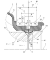
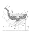
- FIG. 3 shows a partially enlarged cross-sectional view in which part A of FIG. 2 is enlarged and displayed.
- the boot band 8 is indicated by a virtual line for convenience of illustration.
- the mounting structure of the boot member 7 has the same mounting structure for the sleeve shaft 2 and the stub shaft 3. Therefore, for convenience of explanation, only the mounting structure of the boot member 7 and the sleeve shaft 2 will be described below, and the description of the mounting structure of the boot member 7 and the stub shaft 3 will be omitted.
- the boot member 7 is provided at the rear end portion and is provided at the first mounting base 71 which is attached to the sleeve shaft 2 via the boot band 8 and is provided at the front end portion via the boot band 8. It has a second mounting base 72 that is mounted on the stub shaft 3, and a bellows 73 that is provided between the first mounting base 71 and the second mounting base 72 and is formed so as to be expandable and contractible in the axial direction.
- the first mounting base 71 and the second mounting base 72 have the same configuration, a specific configuration will be described below only for the first mounting base 71, and the configuration of the second mounting base 72 will be described. Omits the description.
- the first mounting base 71 has a substantially cylindrical shape, is formed so as to project in the direction of the rotation axis Z in the radial direction, and has a projecting portion 74 that can be fitted or accommodated in a fitting groove 26 which is a groove portion described later. It has a boot band fastening portion 75, which is provided on the opposite side of the protruding portion 74 in the radial direction and is used for fastening the boot band 8. Further, the bottom portion 750 of the boot band fastening portion 75 is provided with a recess 76 recessed in the radial direction toward the rotation axis Z.
- the protruding portion 74 has an arcuate shape in the cross section in the axial direction, is configured as a so-called ridge that is continuous in the circumferential direction over the entire circumference of the first mounting base 71, and is fitted into a fitting groove 26 described later. It is used for axially positioning the boot member 7 with respect to the sleeve shaft 2.
- the protruding portion 74 is provided at a substantially central position in the axial range of the first mounting base portion 71.
- the protrusion 74 is from the center P of the arc surface 740 of the protrusion 74 (the center P of the axial width of the recess 76 described later) to both ends of the boot band fastening portion 75. It is provided at a position where the distances L1 and L2 to the first end portion 751 and the second end portion 752 are substantially equal.
- the axial width W1 of the protruding portion 74 is set to be slightly larger than the axial width W2 of the opening of the fitting groove 26 described later, which is the mating side of the protruding portion 74.
- the inner diameter D1 of the protruding portion 74 is slightly smaller than the outer diameter X1 of the first outer diameter portion 231 of the sleeve shaft 2 (sleeve shaft base portion 23) described later, and is smaller than the outer diameter D2 of the fitting groove 26 described later. It is set large.
- the protruding portion 74 is formed by fastening the first mounting base portion 71, which will be described later, with the boot band 8, so that both ends in the axial direction of the arc surface 740 of the protruding portion 74 (first and second contact portions 741). 742) abuts on the first and second connecting portions 261,262 of the fitting groove 26, which will be described later, to exert a sealing action.
- the length Y2 from the rotation axis Z to the second contact portion 742 is more than the length Y2 from the rotation axis Z to the first contact portion 741.
- the length up to Y1 is shorter.
- the boot band fastening portion 75 is formed in a concave shape on the outer peripheral side of the first mounting base 71 in the radial direction toward the rotation axis Z, and is continuous in the circumferential direction over the entire circumference of the first mounting base 71. It is configured as a so-called annular groove. Further, the boot band fastening portion 75 has an axial width W4 slightly larger than the axial width W3 of the boot band 8.
- the bottom 750 of the boot band fastening portion 75 is formed with a recess 76 recessed from the outside to the inside (toward the protrusion 74 side) in the radial direction on the opposite side in the radial direction of the protrusion 74.
- the recess 76 is formed in a substantially rectangular shape in the cross section in the axial direction, and is continuously provided in the circumferential direction over the entire circumference of the boot band fastening portion 75. Since the recess 76 is provided, the rigidity in the vicinity of the protruding portion 74 is reduced, and when the boot band 8 is fastened to the boot band fastening portion 75, the tightening force (binding force) of the boot band 8 is increased. It is easily transmitted to the protruding portion 74, and the first and second contact portions 741,742 of the protruding portion 74 can be brought into close contact with the first and second connecting portions 261,262 of the fitting groove 26 described later.
- a fitting groove 26 into which the protruding portion 74 can be fitted is provided around the entire circumference of the outer peripheral surface of the sleeve shaft base 23. It is formed continuously in the direction.
- the fitting groove 26 is provided with a groove bottom portion 260 parallel to the rotation axis Z and a first connection portion 261 provided on the front end side of the groove bottom portion 260 and connecting the groove bottom portion 260 and the first outer diameter portion 231 described later.
- a second connecting portion 262 provided on the rear end side of the groove bottom portion 260 and connecting the groove bottom portion 260 and the second outer diameter portion 232 described later, and the vertical cross section (axial cross section) is substantially rectangular. It is formed so as to be. Further, the first connection portion 261 and the second connection portion 262 are formed so as to be inclined with respect to the groove bottom portion 260. That is, the first connection portion 261 and the second connection portion 262 are formed so that the angles ⁇ 1 and ⁇ 2 formed by the first connection portion 261 and the second connection portion 262 and the groove bottom portion 260 are obtuse angles, respectively. In the present embodiment, the angle ⁇ 1 formed by the first connecting portion 261 and the groove bottom portion 260 and the angle ⁇ 2 formed by the second connecting portion 262 and the groove bottom portion 260 are set to be substantially the same.
- the sleeve shaft base 23 of the sleeve shaft 2 is located in front of and behind the fitting groove 26, that is, on the first outer diameter portion 231 formed on the front end side of the fitting groove 26 and on the rear end side of the fitting groove 26.
- the second outer diameter portion 232 formed has a different outer diameter. Specifically, in the sleeve shaft base portion 23, the outer diameter X2 of the second outer diameter portion 232 is set to be larger than the outer diameter X1 of the first outer diameter portion 231.
- the sleeve shaft base 23 has the first outer diameter portion 231 which is on the front side with respect to the outer diameter X2 of the second outer diameter portion 232 which is the back side in the insertion direction of the boot member 7 with respect to the sleeve shaft 2.
- the outer diameter X1 is formed to be relatively small.
- the outer diameter X1 of the first outer diameter portion 231 is set to be slightly larger than the inner diameter D1 of the protruding portion 74 of the boot member 7, and has a predetermined tightening allowance for the protruding portion 74.
- the protruding portion 74 is hooked on the first connecting portion 261 of the fitting groove 26. That is, with the boot member 7 inserted into the sleeve shaft 2 (sleeve shaft base 23), the protruding portion 74 is caught in the first connecting portion 261 of the fitting groove 26 by the tightening force (binding force) of the boot member 7 itself.
- the boot member 7 can be positioned in the axial direction with respect to the sleeve shaft 2. As a result, when the boot member 7 is fastened by the boot band 8, the displacement of the boot member 7 in the axial direction with respect to the sleeve shaft 2 is suppressed, and the boot member 7 can be easily fastened.
- the outer diameter X2 of the second outer diameter portion 232 is set to be larger than the outer diameter X1 of the first outer diameter portion 231 and is set sufficiently larger than the inner diameter D1 of the protruding portion 74 of the boot member 7. There is. That is, in the outer diameter X2 of the second outer diameter portion 232, when the boot member 7 is inserted into the sleeve shaft 2, the protruding portion 74 is caught by the second connecting portion 262 of the fitting groove 26, and the second connecting portion 262 is engaged. The outer diameter is set so that it is difficult to ride on the second outer diameter portion 232.
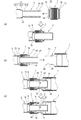
- FIG. 4 is a vertical cross-sectional view of a main part of the propeller shaft PS showing a method of manufacturing the propeller shaft PS, in which (a) is the first step, (b) is the second step, and (c) is the third step. Shown.
- the second mounting base portion 72 of the boot member 7 is mounted on the outer peripheral surface of the stub shaft 3 (medium diameter portion 312 of the first tubular base portion 31). That is, the boot member 7 is inserted from the rear end side of the sleeve shaft side connecting portion 32 of the stub shaft 3, and the boot member 7 is inserted into the fitting groove 37 provided on the outer peripheral side of the medium diameter portion 312 of the first tubular base portion 31.
- the protruding portion 74 provided on the inner peripheral side of the second mounting base portion 72 of the above is fitted.
- the boot band 8 is fastened to the boot band fastening portion 75 provided on the outer peripheral side of the second mounting base 72 of the boot member 7, and the second mounting base 72 of the boot member 7 is fixed to the stub shaft 3.
- the sleeve shaft side connecting portion 32 of the stub shaft 3 to which the second mounting base portion 72 of the boot member 7 is attached is attached to the inner peripheral portion of the sleeve shaft 2. insert. That is, while fitting the male spline portion 34 of the sleeve shaft side connection portion 32 of the stub shaft 3 to the female spline portion 25 of the sleeve shaft 2, the sleeve shaft side connection portion 32 of the stub shaft 3 is connected to the inner peripheral side of the sleeve shaft 2. Insert in.
- the first mounting base 71 of the boot member 7 is replaced with the sleeve shaft of the sleeve shaft 2. It is inserted from the tip end side of the base portion 23, and the protruding portion 74 provided on the first mounting base portion 71 of the boot member 7 is fitted into the fitting groove 26 of the sleeve shaft 2.
- the boot band 8 is fastened to the boot band fastening portion 75 of the first mounting base 71 of the boot member 7, and the first mounting base 71 of the boot member 7 is fixed to the sleeve shaft 2.
- the outer diameters of the first and second shaft portions are set to be the same size before and after the fitting groove in the boot member insertion direction. Therefore, when the boot member is inserted into the first and second shaft portions, it is necessary to extraly expand the inner diameter of the boot member by the amount of protrusion of the protruding portion, and the assembling workability is not good.
- the propeller shaft PS according to the present embodiment can solve the problem of the conventional propeller shaft by achieving the following effects.
- the propeller shaft PS is a propeller shaft that transmits a rotational force from a vehicle power source to the wheels of the vehicle, and is a tubular boot member, which is in the radial direction with respect to the rotation axis Z of the boot member 7.
- a boot member 7 having a protruding portion 74 protruding inward and a boot band fastening portion 75 provided on the opposite side of the protruding portion 74 in the radial direction and recessed toward the rotation axis Z, and a boot member.
- the outer diameter X1 of the first outer diameter portion 231 which has been conventionally set to the same outer diameter as the outer diameter X2 of the second outer diameter portion 232 is the outer diameter of the second outer diameter portion 232. It is set to be relatively smaller than the diameter X2.
- the protruding portion 74 is expanded. The diameter can be reduced.
- the protruding portion 74 can be fitted into the fitting groove 26 with a smaller diameter expansion amount than before, and the workability of inserting the boot member 7 into the shaft member (sleeve shaft 2) can be improved. ..
- the outer diameter X1 of the first outer diameter portion 231 is set to be larger than the inner diameter D1 of the protruding portion 74, and the outer diameter X2 of the second outer diameter portion 232 is larger than the outer diameter X1 of the first outer diameter portion 231.
- the shaft member ( The workability of inserting the boot member 7 into the sleeve shaft 2) can be improved.
- the shaft member (sleeve shaft 2) has a groove bottom portion 260 of the groove portion (fitting groove 26), a first connecting portion 261 connected to the first outer diameter portion 231 and a groove portion (fitting groove 26).
- the groove bottom portion 260 and the second connecting portion 262 connecting to the second outer diameter portion 232 are provided, and the length from the rotation axis Z to the first connection portion 261 in the radial direction is the direction of the rotation axis Z.
- the length is gradually shortened from the first outer diameter portion 231 toward the groove bottom portion 260 of the groove portion (fitting groove 26), and the length from the rotation axis Z to the second connection portion 262 in the radial direction is the rotation axis Z.
- the boot member 7 is gradually formed longer from the groove bottom portion 260 of the groove portion (fitting groove 26) toward the second outer diameter portion 232, and the boot member 7 is in contact with the first contact portion 741 that abuts on the first connection portion 261.
- the length up to part 741 is shorter.
- the first and second contact portions 741 and 742 of the protruding portion 74 of the boot member 7 correspond to the first and second connecting portions 261,262 of the groove portion (fitting groove 26), respectively. It is configured to be in contact.
- the protruding portion 74 of the boot member 7 is configured to contact the groove portion (fitting groove 26) at two points, the first and second contact portions 741 and 742.
- the sealing property of the protruding portion 74 in the groove portion (fitting groove 26) is improved, and as a result, the leakage of grease (not shown) from the inside and the infiltration of muddy water and the like from the outside can be suppressed. ..
- the second outer diameter portion 232 of the sleeve shaft 2 is formed to have a diameter larger than the inner diameter D1 of the protruding portion 74 of the boot member 7 (first mounting base portion 71).
- the second outer diameter portion 232 of the sleeve shaft 2 has an outer diameter X2 larger than the inner diameter D1 of the protruding portion 74 of the first mounting base portion 71 of the boot member 7.
- the protruding portion 74 can be easily fitted into the fitting groove 26, and the seating property of the protruding portion 74 with respect to the fitting groove 26 is improved.
- the protruding portion 74 is easily caught by the second connecting portion 262 of the fitting groove 26, and the adhesion between the protruding portion 74 and the fitting groove 26 (particularly the second connecting portion 262) is improved.
- the sealing property between the protruding portion 74 and the fitting groove 26 can be improved, and the infiltration of water from the first mounting base 71 side of the boot member 7 can be effectively suppressed.
- a rod member stub shaft 3
- a tubular boot member 7 attached to the rod member (stub shaft 3).
- a protruding portion 74 projecting in the radial direction with respect to the rotating axis Z toward the rotating axis Z, and a boot band fastening portion 75 provided on the opposite side of the protruding portion 74 in the radial direction and recessed toward the rotating axis Z.
- a tubular shaft member (sleeve shaft 2) into which the tip of the rod member (stub shaft 3) is inserted and partially covered by the boot member 7, and which is of the rotation axis Z.
- the first outer diameter portion 231 formed to have a diameter larger than the inner diameter D1 of the protruding portion 74 and the first outer diameter portion 231 formed to have a smaller diameter than the first outer diameter portion 231 are formed in order from the tip end portion of the shaft member (sleeve shaft 2).
- a shaft member (sleeve shaft 2) having a fitting groove 26 into which the protruding portion 74 is fitted, a second outer diameter portion 232 formed to have a diameter larger than that of the first outer diameter portion 231, and the second outer diameter portion 232 are provided.
- the first step of attaching the boot member 7 to the rod member (stub shaft 3) and the rod member (stub shaft 3) are inserted into the inner peripheral portion of the shaft member (sleeve shaft 2). It includes a second step and a third step of fitting the protruding portion 74 into the fitting groove 26.
- the outer diameter X1 of the first outer diameter portion 231 which has been conventionally set to the same outer diameter as the outer diameter X2 of the second outer diameter portion 232 is the outer diameter of the second outer diameter portion 232. It is set to be relatively smaller than the diameter X2.
- the protruding portion 74 is expanded. The diameter can be reduced.
- the protruding portion 74 can be fitted into the fitting groove 26 with a smaller diameter expansion amount than before, and the workability of inserting the boot member 7 into the shaft member (sleeve shaft 2) can be improved. ..
- the outer diameter X1 of the first outer diameter portion 231 is set to be larger than the inner diameter D1 of the protruding portion 74, and the outer diameter X2 of the second outer diameter portion 232 is larger than the outer diameter X1 of the first outer diameter portion 231.
- the protruding portion 74 can be reliably fitted in the fitting groove 26 because the setting is large.
- the axial movement of the boot member 7 is surely restricted, and the problem that the protruding portion 74 gets over the fitting groove 26 and rides on the second outer diameter portion 232 is suppressed. From this point of view, the workability of inserting the boot member 7 into the shaft member (sleeve shaft 2) can be improved.
- the boot member 7 is formed by blow molding.
- the boot member 7 is formed by blow molding a resin material, the mold for molding the boot member 7 is sufficient only on the outer peripheral side of the boot member 7, and the boot. There is an advantage that the member 7 can be molded relatively easily. As a result, it is possible to reduce the manufacturing cost of the propeller shaft PS and improve the productivity.
- a fitting groove 37 into which the protruding portion 74 is fitted is formed on the outer peripheral surface of the rod member (sleeve shaft side connecting portion 32 of the stub shaft 3). ..
- the protruding portion 74 provided on the inner peripheral side of the second mounting base portion 72 of the boot member 7 is fitted on the outer peripheral surface of the rod member (sleeve shaft side connecting portion 32 of the stub shaft 3).
- a fitting groove 37 for fitting is provided.
- the second mounting base 72 of the boot member 7 also improves the workability of inserting the boot member 7 into the rod member (sleeve shaft side connecting portion 32 of the stub shaft 3), similarly to the first mounting base 71. Can be done.
- FIG. 5 shows a second embodiment of the propeller shaft according to the present invention, in which the configuration of the fitting groove 26 in the sleeve shaft 2 of the propeller shaft PS according to the first embodiment is changed. Since the basic configurations other than these changes are the same as those in the first embodiment, the same configurations as those in the first embodiment are designated by the same reference numerals, and the description thereof will be omitted. .. Further, in the description of the embodiment, for convenience, the left side of FIG. 5 is referred to as "front” and the right side is referred to as “rear”, and the direction along the rotation axis Z of FIG. 5 is defined as "axial direction” and rotation axis Z. The direction orthogonal to each other will be described as “diametrical direction”, and the direction around the rotation axis Z will be described as “circumferential direction”.
- FIG. 5 is an enlarged view of a main part of the propeller shaft PS according to the second embodiment of the present invention, and is an enlarged view of part A of FIG. 2 as in FIG.
- the first virtual line V1 orthogonal to the rotation axis Z of the boot member 7 when the first virtual line V1 orthogonal to the rotation axis Z of the boot member 7 is defined, the first virtual line V1 and the first connection portion 261 of the fitting groove 26
- the angle ⁇ 3 formed by the above is smaller than the angle ⁇ 4 formed by the first virtual line V1 and the second connecting portion 262 of the fitting groove 26.
- the inclination angle ⁇ 1 of the first connection portion 261 with respect to the groove bottom portion 260 of the fitting groove 26 is larger than the inclination angle ⁇ 2 of the second connection portion 262 with respect to the groove bottom portion 260 of the fitting groove 26. It is set.
- the angle ⁇ 3 formed by the groove bottom portion 260 of the groove portion (fitting groove 26) and the first connection portion 261 is formed. It is smaller than the angle ⁇ 4 formed by the groove bottom portion 260 of the groove portion (fitting groove 26) and the second connecting portion 262.
- the amount of bite of the boot member 7 related to the first connection portion 261 side with respect to the groove portion (fitting groove 26) can be made larger than the amount of bite of the boot member 7 related to the second connection portion 262 side. It becomes.
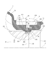
- FIG. 6 shows a third embodiment of the propeller shaft according to the present invention, in which the configuration of the fitting groove 26 in the sleeve shaft 2 of the propeller shaft PS according to the first embodiment is changed. Since the basic configurations other than these changes are the same as those in the first embodiment, the same configurations as those in the first embodiment are designated by the same reference numerals, and the description thereof will be omitted. .. Further, in the description of the embodiment, for convenience, the left side of FIG. 6 will be referred to as “front” and the right side will be referred to as “rear”, and the direction along the rotation axis Z of FIG. 6 will be referred to as “axial direction” and rotation axis Z. The direction orthogonal to each other will be described as “diametrical direction”, and the direction around the rotation axis Z will be described as "circumferential direction”.
- FIG. 6 is an enlarged view of a main part of the propeller shaft PS according to the third embodiment of the present invention, and is an enlarged view of part A of FIG. 2 as in FIG.
- a convex portion 27 projecting outward in the radial direction (opposite side of the protruding portion 74) is provided on the edge.
- the convex portion 27 is formed to have an outer diameter X3 that is larger than the outer diameter X1 of the first outer diameter portion 231 and smaller than the outer diameter X2 of the second outer diameter portion 232.
- the shaft member (sleeve shaft 2) has the first outer diameter portion 231 between the first outer diameter portion 231 and the groove portion (fitting groove 26) in the direction of the rotation axis Z. It has a convex portion 27 formed having a diameter larger than the outer diameter X1 of the above and a diameter smaller than the outer diameter X2 of the second outer diameter portion 232.
- the protruding portion 74 comes into contact with the opening edge of the groove portion (fitting groove 26) on the first outer diameter portion 231 side even more strongly.
- the adhesion between the protruding portion 74 and the first connecting portion 261 of the groove portion (fitting groove 26) is improved, and the sealing property between the protruding portion 74 and the groove portion (fitting groove 26) is improved. be able to.
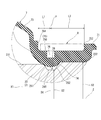
- FIG. 7 shows a fourth embodiment of the propeller shaft according to the present invention, in which the arrangement of the recesses 76 in the boot band fastening portion 75 of the propeller shaft PS according to the first embodiment is changed. Since the basic configurations other than these changes are the same as those in the first embodiment, the same configurations as those in the first embodiment are designated by the same reference numerals, and the description thereof will be omitted. .. Further, in the description of the embodiment, for convenience, the left side of FIG. 7 is referred to as “front” and the right side is referred to as “rear”, and the direction along the rotation axis Z of FIG. 7 is defined as “axial direction” and rotation axis Z. The direction orthogonal to each other will be described as “diametrical direction”, and the direction around the rotation axis Z will be described as "circumferential direction”.
- FIG. 7 is an enlarged view of a main part of the propeller shaft PS according to the fourth embodiment of the present invention, and is an enlarged view of part A of FIG. 2 as in FIG.
- the protruding portion 74 is unevenly arranged on the bellows portion 73 side (the side opposite to the opening of the first mounting base portion 71) in the axial direction. That is, the protruding portion 74 is the second end portion of the boot band fastening portion 75 from the center P of the arc surface 740 of the protruding portion 74 (the center P of the axial width of the recess 76) in the axial range of the first mounting base 71.
- the distance L2 to 752 is provided at a position larger than the distance L1 from the center P to the first end 751 of the boot band fastening portion 75.
- the boot band fastening portion 75 is the first end portion 751 provided on the first outer diameter portion 231 side in the direction of the rotation axis Z and the first end portion 751 in the direction of the rotation axis Z. 2 It has a second end portion 752 provided on the outer diameter portion 232 side and a recess 76 recessed inward in the radial direction in the radial direction, and from the recess 76 in the direction of the rotation axis Z. It is the width from the recess 76 to the second end 752 than the first width (distance L1 from the center P to the first end 751 of the boot band fastening 75), which is the width to the first end 751.
- the second width portion (distance L2 from the center P to the second end portion 752 of the boot band fastening portion 75) is longer.
- the protruding portion 74 is provided unevenly toward the bellows portion 73 side, and the boot is provided from the recess 76 rather than the distance L1 from the recess 76 to the first end portion 751 of the boot band fastening portion 75.
- the distance L2 to the second end portion 752 of the band fastening portion 75 is set large.
- the contact area of the second outer diameter portion 232 with the boot member 7 (first mounting base portion 71) is increased, and the adhesion between the first mounting base portion 71 and the second outer diameter portion 232 is improved.
- the infiltration of water from the opening of the first mounting base 71 of the boot member 7 can be suppressed more effectively.
- FIG. 8 shows a fifth embodiment of the propeller shaft according to the present invention, in which the configuration of the protruding portion 74 of the boot member 7 of the propeller shaft PS according to the first embodiment is changed. Since the basic configurations other than these changes are the same as those in the first embodiment, the same configurations as those in the first embodiment are designated by the same reference numerals, and the description thereof will be omitted. .. Further, in the description of the embodiment, for convenience, the left side of FIG. 8 is referred to as “front” and the right side is referred to as “rear”, and the direction along the rotation axis Z of FIG. 8 is defined as “axial direction” and rotation axis Z. The direction orthogonal to each other will be described as “diametrical direction”, and the direction around the rotation axis Z will be described as "circumferential direction”.
- FIG. 8 is an enlarged view of a main part of the propeller shaft PS according to the fifth embodiment of the present invention, and is an enlarged view of part A of FIG. 2 as in FIG.
- the outer surface of the protruding portion 74 corresponding to the inner peripheral surface of the protruding portion 74 of the boot member 7 corresponds to the outer peripheral surface of the fitting groove 26 of the sleeve shaft 2. It is formed in a shape corresponding to the inner surface of 26, that is, a similar shape that can be closely attached to the fitting groove 26.
- the inner peripheral surface of the protruding portion 74 has a shape corresponding to the outer peripheral surface of the groove portion (fitting groove 26). As a result, almost the entire outer surface of the protruding portion 74 corresponding to the inner peripheral surface of the protruding portion 74 is brought into close contact with the outer peripheral surface of the groove portion (fitting groove 26) corresponding to the inner surface of the groove portion (fitting groove 26). It becomes possible. As a result, the sealing property between the protruding portion 74 and the groove portion (fitting groove 26) can be easily and surely improved.
- the outer surface of the protruding portion 74 corresponding to the inner peripheral surface of the protruding portion 74 corresponds to the inner surface of the groove portion (fitting groove 26) corresponding to the outer peripheral surface of the groove portion (fitting groove 26). It is possible to prevent the portion 74 from coming into contact with a corner portion formed in the vicinity of the groove portion (fitting groove 26) such as the opening edge of the groove portion (fitting groove 26). As a result, the durability (life) of the boot member 7 is improved, and good sealing performance by the protruding portion 74 can be maintained for a long time.
- FIG. 9 shows a sixth embodiment of the propeller shaft according to the present invention, in which the configuration of the boot band fastening portion 75 of the boot member 7 of the propeller shaft PS according to the first embodiment is changed. Since the basic configurations other than these changes are the same as those in the first embodiment, the same configurations as those in the first embodiment are designated by the same reference numerals, and the description thereof will be omitted. .. Further, in the description of the embodiment, for convenience, the left side of FIG. 9 is referred to as "front” and the right side is referred to as “rear”, and the direction along the rotation axis Z of FIG. 9 is defined as "axial direction” and rotation axis Z. The direction orthogonal to each other will be described as “diametrical direction”, and the direction around the rotation axis Z will be described as "circumferential direction”.
- FIG. 9 is an enlarged view of a main part of the propeller shaft PS according to the sixth embodiment of the present invention, and is an enlarged view of part A of FIG. 2 as in FIG.
- a recess 76 is formed in a stepped shape toward the second end portion 752 side in the bottom portion 750 of the boot band fastening portion 75. That is, the bottom portion 750 of the boot band fastening portion 75 is provided at the central position in the axial direction, and is provided on the first recess 76 corresponding to the recess 76 of the first embodiment and on the second end portion 752 side of the first recess 76. It has a second recess 77, which is provided adjacent to the first recess and has a depth DP2 shallower than the depth DP1 of the first recess 76.
- the rear end side (opening side of the first mounting base 71) of the protrusion 74 is relative to the front end side (bellows 73 side). It is formed in a gentle slope.
- the rate of increase of the distance Lx from the outer surface of the protruding portion 74 to the rotation axis Z on the rear end side (first mounting base 71 side) of the protruding portion 74 is the front end side (bellows portion 73 side) of the protruding portion 74. It is configured to be smaller than the rate of increase of the distance Lx from the outer surface of the protrusion 74 to the rotation axis Z.
- the boot band fastening portion 75 is provided so as to be connected to the first recess 76 recessed inward in the radial direction and the first recess 76 in the radial direction. In the radial direction, it has a second recess 77 that is recessed inward in the radial direction and is shallower than the first recess 76.
- the insertion resistance due to the protruding portion 74 when the boot member 7 is inserted into the shaft member (sleeve shaft 2) can be reduced, and the workability of inserting the boot member 7 into the shaft member (sleeve shaft 2) can be further improved. it can.
- FIG. 10 shows a seventh embodiment of the propeller shaft according to the present invention, in which the configuration of the boot band fastening portion 75 of the boot member 7 of the propeller shaft PS according to the first embodiment is changed. Since the basic configurations other than these changes are the same as those in the first embodiment, the same configurations as those in the first embodiment are designated by the same reference numerals, and the description thereof will be omitted. .. Further, in the description of the embodiment, for convenience, the left side of FIG. 10 is referred to as “front” and the right side is referred to as “rear”, and the direction along the rotation axis Z of FIG. 10 is defined as “axial direction” and rotation axis Z. The direction orthogonal to each other will be described as “diametrical direction”, and the direction around the rotation axis Z will be described as "circumferential direction”.
- FIG. 10 is an enlarged view of a main part of the propeller shaft PS according to the seventh embodiment of the present invention, and is an enlarged view of part A of FIG. 2 as in FIG. 3, and FIG. Before the boot band 8 is fastened, (b) shows the state after the boot band 8 is fastened.
- a fastening portion side protruding portion 78 projecting toward the boot member 7 is provided integrally with the first mounting base portion 71 of the boot member 7.
- the fastening portion side protrusion 78 is provided at the bottom portion 750 of the boot band fastening portion 75 at the opening edge portion of the fitting groove 26 on the first outer diameter portion 231 side, and has an axial cross section (longitudinal cross section). It is an annular protrusion formed in an arc shape and continuously formed along the circumferential direction.
- the fastening force (bondage force) of the boot band 8 causes the fastening portion side protrusion.
- Part 78 is crushed and deformed. That is, it is possible to improve the tightening force (binding force) of the boot band 8 by the reaction force based on the crushing deformation of the fastening portion side protrusion 78.
- the boot band fastening portion 75 has a fastening portion side protrusion 78 that protrudes toward the boot band 8.
- the boot band fastening portion 75 is provided with the fastening portion side protrusion 78, when the first mounting base 71 of the boot member 7 is fastened by the boot band 8, the fastening portion side protrusion 78 is crushed.
- the tightening force (binding force) of the boot band 8 can be increased based on the reaction force of the boot member 7 (boot band fastening portion 75) generated by the deformation. As a result, the sealing property of the first mounting base 71 of the boot member 7 can be further improved.
- the fastening portion side protrusion 78 is provided at the opening edge portion on the first outer diameter portion 231 side of the fitting groove 26 at the bottom portion 750 of the boot band fastening portion 75.
- the fastening portion side protrusion 78 is provided at the opening edge portion of the fitting groove 26 on the first outer diameter portion 231 side of the bottom portion 750 of the boot band fastening portion 75, whereby the tightening force of the boot band 8 is increased. (Tightening force) acts more greatly on the protruding portion 74 via the protruding portion 78 on the fastening portion side. As a result, from this point of view, the sealing property between the first mounting base 71 and the first outer diameter portion 231 is improved, and the moisture that has entered from the opening side of the first mounting base 71 is more effectively blocked. You can stop it.
- FIG. 11 shows an eighth embodiment of the propeller shaft according to the present invention, and the configuration of the boot band 8 of the propeller shaft PS according to the first embodiment is changed. Since the basic configurations other than these changes are the same as those in the first embodiment, the same configurations as those in the first embodiment are designated by the same reference numerals, and the description thereof will be omitted. .. Further, in the description of the embodiment, for convenience, the left side of FIG. 11 is referred to as "front” and the right side is referred to as “rear”, and the direction along the rotation axis Z of FIG. 11 is defined as "axial direction” and rotation axis Z. The direction orthogonal to each other will be described as “diametrical direction”, and the direction around the rotation axis Z will be described as "circumferential direction”.
- FIG. 11 is an enlarged view of a main part of the propeller shaft PS according to the eighth embodiment of the present invention, and is an enlarged view of part A of FIG. 2 as in FIG.
- a band-side protrusion 81 projecting inward in the radial direction is provided on the surface of the boot band 8 facing the boot band fastening portion 75.
- the band-side protrusion 81 is provided on the inner peripheral surface of the boot band 8 at an axial position facing the opening edge of the fitting groove 26 on the first outer diameter portion 231 side, and has an axial cross section. (Vertical cross section) is an annular protrusion formed in an arc shape and continuously formed along the circumferential direction.
- the band side protrusion 81 bites into the bottom portion 750 of the boot band fastening portion 75. That is, it is possible to improve the tightening force (binding force) of the boot band 8 by the reaction force generated in the boot band fastening portion 75 based on the bite of the band side protrusion 81.
- the boot band 8 has a band-side protrusion 81 projecting toward the boot band fastening portion 75 on the surface facing the boot band fastening portion 75.
- the band-side protrusion 81 is provided on the inner peripheral surface of the boot band 8, when the first mounting base 71 of the boot member 7 is fastened by the boot band 8, the band-side protrusion 81 is based on the bite. , The tightening force (bondage force) by the boot band 8 can be increased. As a result, the sealing property of the first mounting base 71 of the boot member 7 can be further improved.
- the band side protrusion 81 is provided at an axial position facing the opening edge portion on the first outer diameter portion 231 side of the fitting groove 26 in the bottom portion 750 of the boot band fastening portion 75. ..
- the sealing property between the first mounting base 71 and the first outer diameter portion 231 can be improved, and the moisture that has entered from the opening side of the first mounting base 71 can be blocked more effectively. You can stop it.
- the band side protrusion 81 is provided at an axial position facing the opening edge portion on the first outer diameter portion 231 side of the fitting groove 26 at the bottom portion 750 of the boot band fastening portion 75, whereby the boot is provided.
- the tightening force (tightening force) of the band 8 acts on the protruding portion 74 more greatly via the band-side protruding portion 81.
- the sealing property between the first mounting base 71 and the first outer diameter portion 231 is improved, and the moisture that has entered from the opening side of the first mounting base 71 is more effectively blocked. You can stop it.
- the present invention is not limited to the configurations and embodiments exemplified in the above-described embodiment, and any embodiment of the above-mentioned effects of the present invention can be freely applied according to specifications, costs, and the like. It can be changed.
- the first shaft portion (not shown) is used as the output shaft of the transmission of the vehicle
- the second shaft portion (not shown) is used as the input shaft of the differential device of the vehicle. The reverse may be true.
- the first shaft portion may be the output shaft of the engine and the second shaft portion may be the input shaft of the transmission. The reverse may be true.
- the first mounting base 71 of the boot member 7 is inserted into the sleeve shaft 2 with the shaft member according to the present invention as the sleeve shaft 2 centering on the first mounting base 71 side of the boot member 7.
- the mounting structure of the boot member 7 according to each of the above embodiments can be similarly applied to the second mounting base 72 side of the boot member 7 with the shaft member according to the present invention as the stub shaft 3.
- the propeller shaft is a propeller shaft that transmits a rotational force from a vehicle power source to the wheels of the vehicle, and is a tubular boot member with respect to the rotation axis of the boot member.
- the boot member having a protruding portion protruding inward in the radial direction in the radial direction and a boot band fastening portion provided on the opposite side of the protruding portion in the radial direction and recessed toward the rotation axis.
- a first outer diameter portion a groove portion having an outer diameter smaller than that of the first outer diameter portion and accommodating the protruding portion, and a groove portion having an outer diameter larger than that of the first outer diameter portion. It includes the shaft member having two outer diameter portions, and a boot band wound around the boot band fastening portion.
- the shaft member has a first connection portion that connects the groove bottom portion of the groove portion and the first outer diameter portion, and a second connection that connects the groove bottom portion of the groove portion and the second outer diameter portion.
- the length from the rotation axis to the first connection portion in the radial direction gradually approaches the groove bottom portion of the groove portion from the first outer diameter portion in the direction of the rotation axis. It is formed shorter, and the length from the rotating axis to the second connecting portion in the radial direction is gradually increased as it approaches the second outer diameter portion from the groove bottom portion of the groove portion in the direction of the rotating axis.
- the boot member has a first contact portion that contacts the first connection portion and a second contact portion that contacts the second connection portion, and the boot member has a second contact portion that contacts the second connection portion, and the boot member has the rotation axis in the radial direction.
- the length from the rotation axis to the first contact portion is shorter than the length to the second contact portion.
- the angle formed by the groove bottom of the groove and the first connection when viewed from a cross section orthogonal to the rotation axis is determined by the groove bottom of the groove. Is smaller than the angle formed by the second connecting portion.
- the boot band is formed of a resin material.
- the shaft member is located outside the first outer diameter portion between the first outer diameter portion and the groove portion in the direction of the rotation axis. It has a convex portion formed having a diameter larger than the diameter and a diameter smaller than the outer diameter of the second outer diameter portion.
- the boot band fastening is with a first end provided on the first outer diameter side in the direction of the rotation axis and the rotation. In the direction of the axis, it has a second end portion provided on the side of the second outer diameter portion, and in the radial direction, a recess recessed inward in the radial direction, and in the direction of the rotation axis.
- the second width portion which is the width from the recess to the second end portion, is longer than the first width portion, which is the width from the recess to the first end portion.
- the inner peripheral surface of the protruding portion has a shape corresponding to the outer peripheral surface of the groove portion.
- the boot band fastening is connected to the first recess in the radial direction and the first recess recessed inward in the radial direction. It has a second recess that is shallower than the first recess in the radial direction and is recessed inward in the radial direction.
- the boot band fastening has a fastening side protrusion that projects toward the boot band.
- the boot band has a band-side protrusion that projects toward the boot band fastening on a surface facing the boot band fastening.
- the rod member and the tubular boot member attached to the rod member are provided, and the direction of the rotation axis in the radial direction with respect to the rotation axis of the boot member.
- a boot member having a protruding portion protruding toward the direction and a boot band fastening portion provided on the opposite side of the protruding portion in the radial direction and recessed toward the rotation axis, and a tip portion of the rod member. Is inserted and is a tubular shaft member partially covered by the boot member, and is formed in the direction of the rotation axis in order from the tip end portion of the shaft member to have a diameter larger than the inner diameter of the protruding portion.
- a method of manufacturing a propeller shaft including the shaft member having an outer diameter portion, wherein the boot member is attached to the rod member, and the rod member is attached to the inner peripheral portion of the shaft member. It includes a second step of inserting and a third step of fitting the protruding portion into the fitting groove.
- the boot member is formed by blow molding.
- the fitting groove into which the protruding portion is fitted is formed on the outer peripheral surface of the rod member.
Landscapes
- Engineering & Computer Science (AREA)
- General Engineering & Computer Science (AREA)
- Mechanical Engineering (AREA)
- Chemical & Material Sciences (AREA)
- Combustion & Propulsion (AREA)
- Transportation (AREA)
- Motor Power Transmission Devices (AREA)
- Shafts, Cranks, Connecting Bars, And Related Bearings (AREA)
- Diaphragms And Bellows (AREA)
Priority Applications (4)
| Application Number | Priority Date | Filing Date | Title |
|---|---|---|---|
| JP2021539201A JP7379497B2 (ja) | 2019-08-14 | 2020-07-30 | プロペラシャフト及びその製造方法 |
| EP20852744.0A EP4015879B1 (en) | 2019-08-14 | 2020-07-30 | Propeller shaft and production method therefor |
| US17/634,099 US12196275B2 (en) | 2019-08-14 | 2020-07-30 | Propeller shaft and production method therefor |
| CN202080057499.3A CN114222871A (zh) | 2019-08-14 | 2020-07-30 | 传动轴及其制造方法 |
Applications Claiming Priority (2)
| Application Number | Priority Date | Filing Date | Title |
|---|---|---|---|
| JP2019-148706 | 2019-08-14 | ||
| JP2019148706 | 2019-08-14 |
Publications (1)
| Publication Number | Publication Date |
|---|---|
| WO2021029228A1 true WO2021029228A1 (ja) | 2021-02-18 |
Family
ID=74569426
Family Applications (1)
| Application Number | Title | Priority Date | Filing Date |
|---|---|---|---|
| PCT/JP2020/029219 Ceased WO2021029228A1 (ja) | 2019-08-14 | 2020-07-30 | プロペラシャフト及びその製造方法 |
Country Status (5)
| Country | Link |
|---|---|
| US (1) | US12196275B2 (https=) |
| EP (1) | EP4015879B1 (https=) |
| JP (1) | JP7379497B2 (https=) |
| CN (1) | CN114222871A (https=) |
| WO (1) | WO2021029228A1 (https=) |
Cited By (1)
| Publication number | Priority date | Publication date | Assignee | Title |
|---|---|---|---|---|
| US20230003261A1 (en) * | 2017-01-10 | 2023-01-05 | Gkn Driveline Deutschland Gmbh | Shaft connection |
Families Citing this family (1)
| Publication number | Priority date | Publication date | Assignee | Title |
|---|---|---|---|---|
| JP7320079B2 (ja) * | 2019-12-23 | 2023-08-02 | 日立Astemo株式会社 | 動力伝達軸 |
Citations (11)
| Publication number | Priority date | Publication date | Assignee | Title |
|---|---|---|---|---|
| JPS62138917U (https=) * | 1986-02-25 | 1987-09-02 | ||
| JPH0587254A (ja) * | 1990-06-30 | 1993-04-06 | Draftex Ind Ltd | 可撓性保護ベローズ |
| JPH06341551A (ja) * | 1993-05-31 | 1994-12-13 | Kyoraku Co Ltd | ブーツ |
| JPH0742841A (ja) * | 1993-08-04 | 1995-02-10 | Kyoraku Co Ltd | ブーツの固着構造 |
| JPH07269708A (ja) * | 1994-02-24 | 1995-10-20 | Draftex Ind Ltd | 保護ベローズ |
| JP2000205291A (ja) | 1999-01-20 | 2000-07-25 | Toyoda Mach Works Ltd | 自在継手用ブ―ツ |
| JP2008045675A (ja) * | 2006-08-17 | 2008-02-28 | Ntn Corp | 等速自在継手のブーツ装着構造 |
| JP2008115999A (ja) * | 2006-11-07 | 2008-05-22 | Ntn Corp | ブーツ取り付け構造 |
| JP2009068510A (ja) * | 2007-09-10 | 2009-04-02 | Ntn Corp | 等速自在継手 |
| JP2010112474A (ja) * | 2008-11-06 | 2010-05-20 | Ntn Corp | ブーツの取付構造及びその方法 |
| JP2016156469A (ja) * | 2015-02-25 | 2016-09-01 | Ntn株式会社 | 等速自在継手 |
Family Cites Families (7)
| Publication number | Priority date | Publication date | Assignee | Title |
|---|---|---|---|---|
| US1183064A (en) * | 1914-12-22 | 1916-05-16 | Annette E Emerson | Universal joint. |
| US1381155A (en) * | 1920-11-08 | 1921-06-14 | Joseph P Wood | Universal joint |
| JPS6252220A (ja) * | 1985-08-31 | 1987-03-06 | Toyoda Gosei Co Ltd | 機械軸継手用ブ−ツ |
| US6558262B1 (en) * | 2000-12-22 | 2003-05-06 | Torque-Traction Technologies, Inc. | Boot for slip yoke assembly in a vehicle driveshaft |
| JP2005036945A (ja) * | 2003-07-18 | 2005-02-10 | Toyoda Gosei Co Ltd | 等速ジョイント用ブーツ |
| DE102007034760B4 (de) * | 2007-07-25 | 2014-07-10 | Zf Lenksysteme Gmbh | Faltenbalganschluss |
| JP6211638B2 (ja) * | 2016-02-04 | 2017-10-11 | Ntn株式会社 | 等速自在継手 |
-
2020
- 2020-07-30 JP JP2021539201A patent/JP7379497B2/ja active Active
- 2020-07-30 EP EP20852744.0A patent/EP4015879B1/en active Active
- 2020-07-30 WO PCT/JP2020/029219 patent/WO2021029228A1/ja not_active Ceased
- 2020-07-30 US US17/634,099 patent/US12196275B2/en active Active
- 2020-07-30 CN CN202080057499.3A patent/CN114222871A/zh active Pending
Patent Citations (11)
| Publication number | Priority date | Publication date | Assignee | Title |
|---|---|---|---|---|
| JPS62138917U (https=) * | 1986-02-25 | 1987-09-02 | ||
| JPH0587254A (ja) * | 1990-06-30 | 1993-04-06 | Draftex Ind Ltd | 可撓性保護ベローズ |
| JPH06341551A (ja) * | 1993-05-31 | 1994-12-13 | Kyoraku Co Ltd | ブーツ |
| JPH0742841A (ja) * | 1993-08-04 | 1995-02-10 | Kyoraku Co Ltd | ブーツの固着構造 |
| JPH07269708A (ja) * | 1994-02-24 | 1995-10-20 | Draftex Ind Ltd | 保護ベローズ |
| JP2000205291A (ja) | 1999-01-20 | 2000-07-25 | Toyoda Mach Works Ltd | 自在継手用ブ―ツ |
| JP2008045675A (ja) * | 2006-08-17 | 2008-02-28 | Ntn Corp | 等速自在継手のブーツ装着構造 |
| JP2008115999A (ja) * | 2006-11-07 | 2008-05-22 | Ntn Corp | ブーツ取り付け構造 |
| JP2009068510A (ja) * | 2007-09-10 | 2009-04-02 | Ntn Corp | 等速自在継手 |
| JP2010112474A (ja) * | 2008-11-06 | 2010-05-20 | Ntn Corp | ブーツの取付構造及びその方法 |
| JP2016156469A (ja) * | 2015-02-25 | 2016-09-01 | Ntn株式会社 | 等速自在継手 |
Cited By (2)
| Publication number | Priority date | Publication date | Assignee | Title |
|---|---|---|---|---|
| US20230003261A1 (en) * | 2017-01-10 | 2023-01-05 | Gkn Driveline Deutschland Gmbh | Shaft connection |
| US12188528B2 (en) * | 2017-01-10 | 2025-01-07 | Gkn Driveline Deutschland Gmbh | Shaft connection |
Also Published As
| Publication number | Publication date |
|---|---|
| EP4015879B1 (en) | 2024-09-18 |
| US20220349447A1 (en) | 2022-11-03 |
| JP7379497B2 (ja) | 2023-11-14 |
| EP4015879A1 (en) | 2022-06-22 |
| US12196275B2 (en) | 2025-01-14 |
| EP4015879A4 (en) | 2022-10-19 |
| JPWO2021029228A1 (https=) | 2021-02-18 |
| CN114222871A (zh) | 2022-03-22 |
Similar Documents
| Publication | Publication Date | Title |
|---|---|---|
| JP7001696B2 (ja) | 動力伝達軸 | |
| WO2021029228A1 (ja) | プロペラシャフト及びその製造方法 | |
| JP7256603B2 (ja) | 動力伝達軸 | |
| JP6489344B2 (ja) | 関節シャフトの長さ補償用のシール装置及び関節シャフト | |
| JP2018009583A (ja) | 動力伝達軸 | |
| JP2009085380A (ja) | 等速自在継手 | |
| US6558262B1 (en) | Boot for slip yoke assembly in a vehicle driveshaft | |
| JP4512476B2 (ja) | 継手用ブーツ | |
| JP3444534B2 (ja) | 接続用継手 | |
| WO2023037744A1 (ja) | プロペラシャフト用の等速ジョイントおよびプロペラシャフト | |
| JP2014005915A (ja) | 等速ジョイントの取り付け構造およびプロペラシャフト | |
| JP7214499B2 (ja) | 車両用パワートレインのスプライン摺動部構造 | |
| KR102614131B1 (ko) | 등속조인트 허브 결합구조 | |
| JP4325567B2 (ja) | 動力伝達装置 | |
| JP2007263347A (ja) | 防振ブッシュ | |
| KR101382830B1 (ko) | 드라이브 샤프트의 조인트와 휠 허브의 연결구조 | |
| JP4341954B2 (ja) | 管継手及びパッキン輪ユニット | |
| KR200379822Y1 (ko) | 패킹을 이용한 콜게이트관 연결 구조 | |
| JP6591103B1 (ja) | 動力伝達軸の製造方法 | |
| JP6795405B2 (ja) | ダンパリング | |
| CN112963435A (zh) | 一种软轴总成以及车辆传动系统 | |
| JP2020133763A (ja) | 車両用パワートレインのスプライン摺動部構造 | |
| WO2023120125A1 (ja) | リング部材 | |
| JP2009505000A (ja) | 流体配管装置の継手 | |
| JP2008082432A (ja) | 等速ジョイント用ブーツ締結構造 |
Legal Events
| Date | Code | Title | Description |
|---|---|---|---|
| 121 | Ep: the epo has been informed by wipo that ep was designated in this application |
Ref document number: 20852744 Country of ref document: EP Kind code of ref document: A1 |
|
| ENP | Entry into the national phase |
Ref document number: 2021539201 Country of ref document: JP Kind code of ref document: A |
|
| NENP | Non-entry into the national phase |
Ref country code: DE |
|
| ENP | Entry into the national phase |
Ref document number: 2020852744 Country of ref document: EP Effective date: 20220314 |