WO2021020024A1 - 表示媒体、表示物品及び表示セット - Google Patents
表示媒体、表示物品及び表示セット Download PDFInfo
- Publication number
- WO2021020024A1 WO2021020024A1 PCT/JP2020/026100 JP2020026100W WO2021020024A1 WO 2021020024 A1 WO2021020024 A1 WO 2021020024A1 JP 2020026100 W JP2020026100 W JP 2020026100W WO 2021020024 A1 WO2021020024 A1 WO 2021020024A1
- Authority
- WO
- WIPO (PCT)
- Prior art keywords
- layer
- display
- circularly polarized
- polarized light
- display medium
- Prior art date
- Legal status (The legal status is an assumption and is not a legal conclusion. Google has not performed a legal analysis and makes no representation as to the accuracy of the status listed.)
- Ceased
Links
Images






Classifications
-
- G—PHYSICS
- G02—OPTICS
- G02B—OPTICAL ELEMENTS, SYSTEMS OR APPARATUS
- G02B5/00—Optical elements other than lenses
- G02B5/30—Polarising elements
- G02B5/3025—Polarisers, i.e. arrangements capable of producing a definite output polarisation state from an unpolarised input state
-
- G—PHYSICS
- G02—OPTICS
- G02F—OPTICAL DEVICES OR ARRANGEMENTS FOR THE CONTROL OF LIGHT BY MODIFICATION OF THE OPTICAL PROPERTIES OF THE MEDIA OF THE ELEMENTS INVOLVED THEREIN; NON-LINEAR OPTICS; FREQUENCY-CHANGING OF LIGHT; OPTICAL LOGIC ELEMENTS; OPTICAL ANALOGUE/DIGITAL CONVERTERS
- G02F1/00—Devices or arrangements for the control of the intensity, colour, phase, polarisation or direction of light arriving from an independent light source, e.g. switching, gating or modulating; Non-linear optics
- G02F1/01—Devices or arrangements for the control of the intensity, colour, phase, polarisation or direction of light arriving from an independent light source, e.g. switching, gating or modulating; Non-linear optics for the control of the intensity, phase, polarisation or colour
- G02F1/13—Devices or arrangements for the control of the intensity, colour, phase, polarisation or direction of light arriving from an independent light source, e.g. switching, gating or modulating; Non-linear optics for the control of the intensity, phase, polarisation or colour based on liquid crystals, e.g. single liquid crystal display cells
- G02F1/133—Constructional arrangements; Operation of liquid crystal cells; Circuit arrangements
- G02F1/1333—Constructional arrangements; Manufacturing methods
- G02F1/1335—Structural association of cells with optical devices, e.g. polarisers or reflectors
- G02F1/133528—Polarisers
- G02F1/133541—Circular polarisers
-
- B—PERFORMING OPERATIONS; TRANSPORTING
- B42—BOOKBINDING; ALBUMS; FILES; SPECIAL PRINTED MATTER
- B42D—BOOKS; BOOK COVERS; LOOSE LEAVES; PRINTED MATTER CHARACTERISED BY IDENTIFICATION OR SECURITY FEATURES; PRINTED MATTER OF SPECIAL FORMAT OR STYLE NOT OTHERWISE PROVIDED FOR; DEVICES FOR USE THEREWITH AND NOT OTHERWISE PROVIDED FOR; MOVABLE-STRIP WRITING OR READING APPARATUS
- B42D25/00—Information-bearing cards or sheet-like structures characterised by identification or security features; Manufacture thereof
- B42D25/30—Identification or security features, e.g. for preventing forgery
- B42D25/351—Translucent or partly translucent parts, e.g. windows
-
- B—PERFORMING OPERATIONS; TRANSPORTING
- B42—BOOKBINDING; ALBUMS; FILES; SPECIAL PRINTED MATTER
- B42D—BOOKS; BOOK COVERS; LOOSE LEAVES; PRINTED MATTER CHARACTERISED BY IDENTIFICATION OR SECURITY FEATURES; PRINTED MATTER OF SPECIAL FORMAT OR STYLE NOT OTHERWISE PROVIDED FOR; DEVICES FOR USE THEREWITH AND NOT OTHERWISE PROVIDED FOR; MOVABLE-STRIP WRITING OR READING APPARATUS
- B42D25/00—Information-bearing cards or sheet-like structures characterised by identification or security features; Manufacture thereof
- B42D25/30—Identification or security features, e.g. for preventing forgery
- B42D25/36—Identification or security features, e.g. for preventing forgery comprising special materials
-
- B—PERFORMING OPERATIONS; TRANSPORTING
- B42—BOOKBINDING; ALBUMS; FILES; SPECIAL PRINTED MATTER
- B42D—BOOKS; BOOK COVERS; LOOSE LEAVES; PRINTED MATTER CHARACTERISED BY IDENTIFICATION OR SECURITY FEATURES; PRINTED MATTER OF SPECIAL FORMAT OR STYLE NOT OTHERWISE PROVIDED FOR; DEVICES FOR USE THEREWITH AND NOT OTHERWISE PROVIDED FOR; MOVABLE-STRIP WRITING OR READING APPARATUS
- B42D25/00—Information-bearing cards or sheet-like structures characterised by identification or security features; Manufacture thereof
- B42D25/30—Identification or security features, e.g. for preventing forgery
- B42D25/36—Identification or security features, e.g. for preventing forgery comprising special materials
- B42D25/364—Liquid crystals
-
- G—PHYSICS
- G02—OPTICS
- G02B—OPTICAL ELEMENTS, SYSTEMS OR APPARATUS
- G02B27/00—Optical systems or apparatus not provided for by any of the groups G02B1/00 - G02B26/00, G02B30/00
- G02B27/28—Optical systems or apparatus not provided for by any of the groups G02B1/00 - G02B26/00, G02B30/00 for polarising
- G02B27/283—Optical systems or apparatus not provided for by any of the groups G02B1/00 - G02B26/00, G02B30/00 for polarising used for beam splitting or combining
-
- G—PHYSICS
- G02—OPTICS
- G02B—OPTICAL ELEMENTS, SYSTEMS OR APPARATUS
- G02B27/00—Optical systems or apparatus not provided for by any of the groups G02B1/00 - G02B26/00, G02B30/00
- G02B27/32—Fiducial marks and measuring scales within the optical system
- G02B27/34—Fiducial marks and measuring scales within the optical system illuminated
-
- G—PHYSICS
- G02—OPTICS
- G02B—OPTICAL ELEMENTS, SYSTEMS OR APPARATUS
- G02B5/00—Optical elements other than lenses
- G02B5/08—Mirrors
- G02B5/0808—Mirrors having a single reflecting layer
-
- G—PHYSICS
- G02—OPTICS
- G02B—OPTICAL ELEMENTS, SYSTEMS OR APPARATUS
- G02B5/00—Optical elements other than lenses
- G02B5/30—Polarising elements
- G02B5/3016—Polarising elements involving passive liquid crystal elements
-
- G—PHYSICS
- G02—OPTICS
- G02B—OPTICAL ELEMENTS, SYSTEMS OR APPARATUS
- G02B5/00—Optical elements other than lenses
- G02B5/30—Polarising elements
- G02B5/3025—Polarisers, i.e. arrangements capable of producing a definite output polarisation state from an unpolarised input state
- G02B5/3033—Polarisers, i.e. arrangements capable of producing a definite output polarisation state from an unpolarised input state in the form of a thin sheet or foil, e.g. Polaroid
- G02B5/3041—Polarisers, i.e. arrangements capable of producing a definite output polarisation state from an unpolarised input state in the form of a thin sheet or foil, e.g. Polaroid comprising multiple thin layers, e.g. multilayer stacks
-
- G—PHYSICS
- G02—OPTICS
- G02B—OPTICAL ELEMENTS, SYSTEMS OR APPARATUS
- G02B5/00—Optical elements other than lenses
- G02B5/30—Polarising elements
- G02B5/3025—Polarisers, i.e. arrangements capable of producing a definite output polarisation state from an unpolarised input state
- G02B5/3033—Polarisers, i.e. arrangements capable of producing a definite output polarisation state from an unpolarised input state in the form of a thin sheet or foil, e.g. Polaroid
- G02B5/3041—Polarisers, i.e. arrangements capable of producing a definite output polarisation state from an unpolarised input state in the form of a thin sheet or foil, e.g. Polaroid comprising multiple thin layers, e.g. multilayer stacks
- G02B5/305—Polarisers, i.e. arrangements capable of producing a definite output polarisation state from an unpolarised input state in the form of a thin sheet or foil, e.g. Polaroid comprising multiple thin layers, e.g. multilayer stacks including organic materials, e.g. polymeric layers
-
- G—PHYSICS
- G02—OPTICS
- G02B—OPTICAL ELEMENTS, SYSTEMS OR APPARATUS
- G02B5/00—Optical elements other than lenses
- G02B5/30—Polarising elements
- G02B5/3083—Birefringent or phase retarding elements
-
- G—PHYSICS
- G02—OPTICS
- G02F—OPTICAL DEVICES OR ARRANGEMENTS FOR THE CONTROL OF LIGHT BY MODIFICATION OF THE OPTICAL PROPERTIES OF THE MEDIA OF THE ELEMENTS INVOLVED THEREIN; NON-LINEAR OPTICS; FREQUENCY-CHANGING OF LIGHT; OPTICAL LOGIC ELEMENTS; OPTICAL ANALOGUE/DIGITAL CONVERTERS
- G02F1/00—Devices or arrangements for the control of the intensity, colour, phase, polarisation or direction of light arriving from an independent light source, e.g. switching, gating or modulating; Non-linear optics
- G02F1/01—Devices or arrangements for the control of the intensity, colour, phase, polarisation or direction of light arriving from an independent light source, e.g. switching, gating or modulating; Non-linear optics for the control of the intensity, phase, polarisation or colour
- G02F1/13—Devices or arrangements for the control of the intensity, colour, phase, polarisation or direction of light arriving from an independent light source, e.g. switching, gating or modulating; Non-linear optics for the control of the intensity, phase, polarisation or colour based on liquid crystals, e.g. single liquid crystal display cells
- G02F1/133—Constructional arrangements; Operation of liquid crystal cells; Circuit arrangements
- G02F1/1333—Constructional arrangements; Manufacturing methods
- G02F1/1335—Structural association of cells with optical devices, e.g. polarisers or reflectors
- G02F1/133528—Polarisers
- G02F1/133536—Reflective polarizers
-
- G—PHYSICS
- G02—OPTICS
- G02F—OPTICAL DEVICES OR ARRANGEMENTS FOR THE CONTROL OF LIGHT BY MODIFICATION OF THE OPTICAL PROPERTIES OF THE MEDIA OF THE ELEMENTS INVOLVED THEREIN; NON-LINEAR OPTICS; FREQUENCY-CHANGING OF LIGHT; OPTICAL LOGIC ELEMENTS; OPTICAL ANALOGUE/DIGITAL CONVERTERS
- G02F1/00—Devices or arrangements for the control of the intensity, colour, phase, polarisation or direction of light arriving from an independent light source, e.g. switching, gating or modulating; Non-linear optics
- G02F1/01—Devices or arrangements for the control of the intensity, colour, phase, polarisation or direction of light arriving from an independent light source, e.g. switching, gating or modulating; Non-linear optics for the control of the intensity, phase, polarisation or colour
- G02F1/13—Devices or arrangements for the control of the intensity, colour, phase, polarisation or direction of light arriving from an independent light source, e.g. switching, gating or modulating; Non-linear optics for the control of the intensity, phase, polarisation or colour based on liquid crystals, e.g. single liquid crystal display cells
- G02F1/133—Constructional arrangements; Operation of liquid crystal cells; Circuit arrangements
- G02F1/1333—Constructional arrangements; Manufacturing methods
- G02F1/1335—Structural association of cells with optical devices, e.g. polarisers or reflectors
- G02F1/133528—Polarisers
- G02F1/133543—Cholesteric polarisers
-
- G—PHYSICS
- G09—EDUCATION; CRYPTOGRAPHY; DISPLAY; ADVERTISING; SEALS
- G09F—DISPLAYING; ADVERTISING; SIGNS; LABELS OR NAME-PLATES; SEALS
- G09F19/00—Advertising or display means not otherwise provided for
- G09F19/12—Advertising or display means not otherwise provided for using special optical effects
Definitions
- the present invention relates to a display medium, a display article to be observed through the display medium, and a display set including a combination thereof.
- Circular polarizing plates generally have a function of selectively transmitting one of circular polarization having a clockwise rotation direction (that is, right circular polarization) and circular polarization having a counterclockwise rotation direction (that is, left circular polarization). Have. Utilizing such a function, a circular polarizing plate has been conventionally used for authenticity identification (Patent Documents 1 and 2).
- the present inventor considered that the function of the circular polarizing plate could be utilized in applications other than authenticity identification applications, and attempted to create a new display mode.
- the present invention has been devised in view of the above problems, and an object of the present invention is to provide a display set capable of realizing a new display mode which has never existed in the past, and a display medium and display article applicable to the display set. To do.
- the present inventor has diligently studied to solve the above-mentioned problems.
- the present inventor has a multilayer base material having a polarization separation layer having a circular polarization separation function and a retardation layer, and a reflective layer having a specific circular polarization separation function provided on the surface of the multilayer base material.
- the present invention has been completed by finding that a display set including a combination of a display medium including the above-mentioned and a display article including a base article and a display layer having a circular polarization separation function; can solve the above-mentioned problems. That is, the present invention includes the following.
- a multi-layer base material provided with a polarization separation layer and a retardation layer, and a first reflection layer provided on a surface of the multi-layer base material on the polarization separation layer side are provided.
- the polarization separating layer can reflect circularly polarized light of one rotational direction D A, and transmits the circularly polarized light rotating in the opposite direction
- the first reflective layer can reflect the circularly polarized light in one of the rotation directions D B1 and transmit the circularly polarized light in the opposite rotation direction.
- a display medium in which the rotation direction DA of circularly polarized light that can be reflected by the polarization separation layer and the rotation direction D B1 of circularly polarized light that can be reflected by the first reflective layer are the same.
- a second reflective layer provided on the surface of the multilayer base material on the retardation layer side is provided.
- the second reflective layer can reflect the circularly polarized light in one of the rotation directions DB2 and transmit the circularly polarized light in the opposite rotation direction.
- the rotation direction D A circularly polarized light whose polarization separating layer can be reflected
- the a second reflective layer is the rotating direction D B2 of the circularly polarized light can reflect is reversed, the display medium according to (1).
- a multi-layer base material including a polarizing separation layer and a retardation layer, and a second reflection layer provided on a surface of the multi-layer base material on the retardation layer side are provided.
- the polarization separating layer can reflect circularly polarized light of one rotational direction D A, and transmits the circularly polarized light rotating in the opposite direction
- the second reflective layer can reflect the circularly polarized light in one of the rotation directions DB2 and transmit the circularly polarized light in the opposite rotation direction.
- a display medium in which the rotation direction DA of circularly polarized light that can be reflected by the polarization separation layer and the rotation direction D B2 of circularly polarized light that can be reflected by the second reflective layer are opposite.
- the in-plane retardation of the retardation layer at the measurement wavelength of 590 nm is “ ⁇ (2n + 1) / 2 ⁇ ⁇ 590 nm-30 nm” or more and “ ⁇ (2n + 1) / 2 ⁇ ⁇ 590 nm + 30 nm” or less (however, however). n represents an integer of 0 or more.), The display medium according to any one of [1] to [5].
- the polarization separation layer is a layer of a resin having cholesteric regularity.
- the display article includes a base article and a display layer provided on the base article. Wherein the display layer is capable of reflecting a circularly polarized light of one rotational direction D D, and transmits the circularly polarized light rotating in the opposite direction, the display article.
- a first display layer capable of reflecting circularly polarized light in the same rotation direction D D1 as the rotation direction DA of circularly polarized light that can be reflected by the polarization separation layer and transmitting circularly polarized light in the opposite rotation direction. Reflects circularly polarized light of the polarization rotation direction of the separation layer is circularly polarized light can reflect D A reverse rotation direction D D2, a second display layer which can transmit circularly polarized light rotating in the opposite direction, at least The labeled article according to [9], including one. [11] A display set including the display medium according to any one of [1] to [8] and the display article according to [9] or [10].
- the present invention it is possible to provide a display set capable of realizing a new display mode that has never existed in the past, and a display medium and display article applicable to the display set.
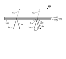
- FIG. 1 is a cross-sectional view schematically showing a display medium according to the first embodiment of the present invention.
- FIG. 2 is a schematic plan view of the display medium according to the first embodiment of the present invention as viewed from one side (the side on which the first reflective layer is provided).
- FIG. 3 is a schematic plan view of the display medium according to the first embodiment of the present invention as viewed from the other side (the side opposite to the side on which the first reflective layer is provided).
- FIG. 4 is a cross-sectional view schematically showing a display medium according to the first embodiment of the present invention.
- FIG. 5 is a cross-sectional view schematically showing a display medium according to the first embodiment of the present invention.
- FIG. 6 is a cross-sectional view schematically showing a display medium according to a second embodiment of the present invention.
- FIG. 7 is a schematic plan view of the display medium according to the second embodiment of the present invention as viewed from one side (the side opposite to the side on which the second reflective layer is provided).
- FIG. 8 is a schematic plan view of the display medium according to the second embodiment of the present invention as viewed from the other side (the side on which the second reflective layer is provided).
- FIG. 9 is a cross-sectional view schematically showing a display medium according to a second embodiment of the present invention.
- FIG. 10 is a cross-sectional view schematically showing a display medium according to a second embodiment of the present invention.
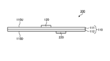
- FIG. 11 is a cross-sectional view schematically showing a display medium according to a third embodiment of the present invention.
- FIG. 12 is a schematic plan view of the display medium according to the third embodiment of the present invention as viewed from one side (the side on which the first reflective layer is provided).
- FIG. 13 is a schematic plan view of the display medium according to the third embodiment of the present invention as viewed from the other side (the side on which the second reflective layer is provided).
- FIG. 14 is a cross-sectional view schematically showing a display set according to a fourth embodiment of the present invention.
- FIG. 15 is a cross-sectional view schematically showing a display article included in the display set according to the fourth embodiment of the present invention.
- FIG. 12 is a schematic plan view of the display medium according to the third embodiment of the present invention as viewed from one side (the side on which the first reflective layer is provided).
- FIG. 13 is a schematic plan view of the display medium according to the third embodiment of the present invention as viewed from the other side (
- FIG. 16 is a plan view schematically showing a display article included in the display set according to the fourth embodiment of the present invention.
- FIG. 17 is a plan view schematically showing an image visually recognized when the display set shown in FIG. 14 is observed from above in the drawing.
- FIG. 18 is a cross-sectional view schematically showing a display set according to a fourth embodiment of the present invention.
- FIG. 19 is a plan view schematically showing an image visually recognized when the display set shown in FIG. 18 is observed from above in the drawing.
- FIG. 20 is a cross-sectional view schematically showing the display set manufactured in the first embodiment.
- FIG. 21 is a cross-sectional view schematically showing the display set manufactured in the second embodiment.
- FIG. 22 is a cross-sectional view schematically showing the display set manufactured in Comparative Example 1.
- FIG. 23 is a cross-sectional view schematically showing the display set manufactured in Comparative Example 2.
- FIG. 24 is a cross-sectional view schematically showing the display set manufactured in Comparative Example 3.
- FIG. 25 is a cross-sectional view schematically showing the display set manufactured in Comparative Example 4.
- nx represents the refractive index in the direction perpendicular to the thickness direction of the layer (in-plane direction) and in the direction giving the maximum refractive index.
- ny represents the refractive index in the in-plane direction orthogonal to the nx direction.
- nz represents the refractive index in the thickness direction.
- d represents the thickness of the layer.
- the measurement wavelength is 590 nm unless otherwise specified.
- circularly polarized light includes elliptically polarized light as long as the effect of the present invention is not significantly impaired.
- a display set includes a display medium and a display article.
- the display medium includes a multi-layer base material including a polarization separation layer and a retardation layer, and a reflection layer such as a first reflection layer and a second reflection layer provided on at least one surface of the multi-layer base material.
- the display article includes a base article and a display layer provided on the base article.
- the multilayer base material included in the display medium can transmit a part of irradiation light such as unpolarized light including both right-handed circularly polarized light and left-handed circularly polarized light.
- the polarization separation layer provided in the multilayer substrate to reflect circularly polarized light of right-handed and one rotational direction D A counterclockwise, capable of transmitting a circularly polarized light rotating in the opposite direction. Therefore, the multilayer base material can be a member that is transparent or translucent with respect to irradiation light.
- the reflective layer included in the display medium is provided so as to reflect circularly polarized light of right-handed and one rotational direction D B counterclockwise, capable of transmitting a circularly polarized light rotating in the opposite direction.
- the rotation direction DB1 of the circularly polarized light that can be reflected by the first reflective layer provided on the surface of the multilayer substrate on the polarization separating layer side is the rotation of the circularly polarized light that can be reflected by the polarizing separating layer. It is set to be the same as the direction D A.
- the "plane on the polarization separation layer side of the multi-layer base material” means that the distance to the polarization separation layer is shorter than the distance to the retardation layer among the front surface and the back surface of the multi-layer base material. Represents the direction.
- the direction of rotation D B2 of the circularly polarized light by the second reflection layer provided on a surface of the retardation layer side can reflect a multilayer substrate is set to reverse the polarization separation layer and the direction of rotation D A circularly polarized light can be reflected Will be done.
- the "plane of the retardation layer of the multi-layer base material" is the front surface and the back surface of the multi-layer base material, whichever has a longer distance to the polarization separation layer than the distance to the retardation layer. Represents the face of.
- the display medium when the display medium is observed from the reflective layer side, strong light reflection occurs in the reflective layer, so that the reflective layer can be visually recognized.
- the display medium when the display medium is observed from the opposite side to the reflective layer, the light is reflected by the reflective layer.
- the reflective layer is invisible because it does not occur or the reflection is weak. Therefore, when the display medium is observed under light containing both right-handed and left-handed circularly polarized light, the image of the display medium that is visually recognized when observed from the front surface while the multilayer base material is transparent or translucent. And the image of the display medium that is visually recognized by observing from the back surface may be different.
- the multilayer substrate is transparent or translucent as described above, at least a part of the display medium may be transparent or translucent. .. Therefore, the observer can observe the displayed article through the display medium.
- the retardation layer included in the multilayer base material changes the polarization state of the light transmitted through the retardation layer, the rotation direction of the circularly polarized light blocked by the multilayer base material is the traveling direction of the circularly polarized light. Can vary depending on.
- the display medium can switch between right-handed circularly polarized light and left-handed circularly polarized light depending on the orientation of the front and back.
- the display layer of the display article is provided so as to reflect the circular polarization in a specific rotation direction and transmit the circular polarization in the opposite rotation direction. Therefore, depending on the orientation of the display medium, the circularly polarized light reflected by the display layer may or may not be blocked by the display medium. Therefore, when the display article is observed through the display medium, the image of the display article observed from the front surface and visually recognized may be different from the image of the display article observed from the back surface.
- the image of the display medium and the image of the display article to be visually recognized may be different depending on the orientation of the display medium. Therefore, by combining different images in this way, a complementary design can be realized, a new display mode that has not existed in the past can be achieved, and a complicated and highly flexible design can be created.
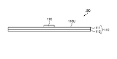
- FIG. 1 is a cross-sectional view schematically showing a display medium 100 according to the first embodiment of the present invention.
- FIG. 2 is a schematic plan view of the display medium 100 according to the first embodiment of the present invention as viewed from one side (the side on which the first reflective layer 120 is provided).
- FIG. 3 is a schematic plan view of the display medium 100 according to the first embodiment of the present invention as viewed from the other side (the side opposite to the side where the first reflective layer 120 is provided).
- the display medium 100 includes reflections provided on the multilayer base material 110 and the surface 110U on the polarization separation layer side of the multilayer base material 110.
- a first reflective layer 120 as a layer is provided.
- the multilayer base material 110 includes a polarizing separation layer 111 and a retardation layer 112.
- the polarization separation layer 111 has a circular polarization separation function.
- the "circular polarization separation function” means a function of reflecting circular polarization in one of the clockwise and counterclockwise rotation directions and transmitting circular polarization in the opposite rotation direction.
- the polarization separating layer 111 in the wavelength range capable of exhibiting the circularly polarized light separation function, reflects circularly polarized light of one rotational direction D A, and transmits the circularly polarized light of opposite direction of rotation and the direction of rotation D A be able to.
- the wavelength range in which the polarization separation layer 111 can exhibit the circular polarization separation function may be appropriately referred to as a “polarization separation wavelength range”.
- the reflectance of the polarization separation layer 111 with respect to unpolarized light in the polarization separation wavelength range is usually 35% to 50%, preferably 40% to 50%.
- the polarization separation wavelength range is preferably in the visible wavelength region.
- the visible wavelength region usually refers to a wavelength region of 400 nm or more and 780 nm or less.
- the wavelength width of the polarization separation wavelength range is wide.
- the wavelength width of the specific polarization separation wavelength range is preferably 70 nm or more, more preferably 100 nm or more, still more preferably 200 nm or more, and particularly preferably 400 nm or more. Since the wavelength width of the polarization separation wavelength range is wide, the range of circularly polarized color that can be reflected by the polarization separation layer 111 can be widened. Therefore, the reflection layer such as the first reflection layer 120 and the display layer of the display article (FIGS. 1 to 1). 3), the degree of freedom in color can be increased, and a display mode with high design can be achieved.
- the upper limit of the wavelength width of the polarization separation wavelength range is not particularly limited, but may be, for example, 600 nm or less.
- a resin layer having cholesteric regularity is preferable.
- a resin having cholesteric regularity may be appropriately referred to as "cholesteric resin” below.
- Cholesteric regularity means that the molecular axes are aligned in a certain direction on one plane, but the direction of the molecular axes shifts at a slight angle on the next plane that overlaps with it, and further shifts on the next plane. As described above, the structure is such that the angle of the molecular axis in the plane is deviated (twisted) as it sequentially passes through the planes arranged in an overlapping manner.
- the molecules inside a layer have cholesteric regularity, the molecules are arranged so that their molecular axes are oriented in a certain direction on a first plane inside the layer.
- the direction of the molecular axis deviates slightly from the direction of the molecular axis in the first plane.
- the direction of the molecular axis is further angled from the direction of the molecular axis in the second plane. In this way, in the planes that are arranged in an overlapping manner, the angles of the molecular axes in the planes are sequentially shifted (twisted).
- Such a structure in which the direction of the molecular axis is twisted is usually a spiral structure and an optically chiral structure.
- the cholesteric resin layer can exert a circular polarization separation function.
- the reflection in the cholesteric resin layer reflects the circularly polarized light while maintaining its chirality.
- the specific wavelength at which the cholesteric resin layer exerts the circular polarization separation function generally depends on the pitch of the helical structure in the cholesteric resin layer.
- the pitch of the spiral structure is the distance in the plane normal direction until the direction of the molecular axis in the spiral structure gradually shifts as it advances in the plane and then returns to the original molecular axis direction.
- the pitch size of this spiral structure it is possible to change the wavelength at which the circular polarization separation function is exhibited.
- the pitch size of the spiral structure for example, the method described in JP-A-2009-300622 can be used.
- Specific examples include a method of adjusting the type of chiral agent and adjusting the amount of the chiral agent in the cholesteric liquid crystal composition.
- the pitch size of the spiral structure is continuously changed in the layer, it is possible to obtain a circular polarization separation function over a wide wavelength range by a single layer of cholesteric resin.
- Examples of the cholesteric resin layer capable of exhibiting the circular polarization separation function in a wide wavelength range include (i) a cholesteric resin layer in which the pitch size of the spiral structure is changed stepwise, and (ii) a spiral structure. Examples thereof include a layer of cholesteric resin in which the size of the pitch is continuously changed.
- the cholesteric resin layer in which the pitch of the spiral structure is changed stepwise can be obtained, for example, by laminating a plurality of cholesteric resin layers having different pitches of the spiral structure.
- Lamination can be performed by preparing a plurality of layers of cholesteric resin having different spiral structures in advance and then fixing each layer with an adhesive or an adhesive.
- the lamination can be performed by forming a layer of a certain cholesteric resin and then sequentially forming another layer of a cholesteric resin.
- the layer of the cholesteric resin in which the pitch size of the spiral structure is continuously changed includes, for example, one or more irradiation treatments of active energy rays and / or heating treatment on the layer of the liquid crystal composition. It can be obtained by curing the layer of the liquid crystal composition after performing the broadband treatment. According to the above-mentioned wide band processing, the pitch of the spiral structure can be continuously changed in the thickness direction, so that the wavelength range (reflection band) in which the cholesteric resin layer can exert the circular polarization separation function can be extended. It can, and is therefore called wideband processing.
- the cholesteric resin layer may be a single-layer structure consisting of only one layer, or a multi-layer structure including two or more layers.
- the number of layers contained in the cholesteric resin layer is preferably 1 to 100, more preferably 1 to 20, from the viewpoint of ease of production.
- the cholesteric liquid crystal composition refers to a composition capable of exhibiting a liquid crystal phase (cholesteric liquid crystal phase) in which the liquid crystal compound has cholesteric regularity when the liquid crystal compound contained in the liquid crystal composition is oriented.
- the material referred to as a "liquid crystal composition” for convenience includes not only a mixture of two or more substances but also a material composed of a single substance.
- Specific examples of the method for producing the cholesteric resin layer include the methods described in JP-A-2014-174471 and JP-A-2015-27743.
- the twisting direction in the cholesteric regularity can be appropriately selected depending on the structure of the chiral agent contained in the liquid crystal composition.
- a cholesteric liquid crystal composition containing a chiral agent which imparts dextrorotatory properties is used, and when the twist direction is counterclockwise, a cholesteric liquid crystal composition containing a chiral agent which imparts dextrorotatory properties is used.
- a liquid crystal composition can be used.
- the thickness of the polarizing separation layer 111 is preferably 2 ⁇ m or more, more preferably 3 ⁇ m or more, preferably 1000 ⁇ m or less, and more preferably 500 ⁇ m or less.
- the thickness of the polarizing separation layer 111 is equal to or greater than the lower limit of the above range, the reflective layer is visually recognized when the display medium 100 is observed from the side opposite to the side where the reflective layer such as the first reflective layer 120 is provided. It can be made difficult.
- the thickness of the polarizing separation layer 111 is not more than the upper limit of the above range, the transparency can be enhanced.
- the retardation layer 112 is a layer having a specific range of in-plane retardation Re provided on one side of the polarization separation layer 111.
- a part or the whole of the retardation layer 112 overlaps a part or the whole of the polarization separation layer 111. That is, the position in the in-plane direction perpendicular to the thickness direction of the display medium 100 is the same for a part or the whole of the retardation layer 112 and a part or the whole of the polarization separation layer 111.
- an example in which the entire retardation layer 112 and the entire polarization separation layer 111 overlap when viewed from the thickness direction will be described.
- the range of the in-plane retardation Re of the retardation layer 112 is such that an image visually recognized by observing one side of the display medium 100 and an image visually recognized by observing the other side of the display medium 100 are desired designs. It can be set within a range that differs to the extent that sex can be obtained. Normally, the in-plane retardation Re of the retardation layer 112 is set so that the rotation direction of the circularly polarized light transmitted through the polarization separation layer can be reversed.
- the specific range of the in-plane retardation Re of the retardation layer 112 is preferably " ⁇ (2n + 1) / 2 ⁇ x 590 nm-30 nm" or more, more preferably " ⁇ (2n + 1) /" at the measurement wavelength of 590 nm.
- n represents an integer of 0 or more.
- the retardation layer 112 having the in-plane retardation Re in the above range at the measurement wavelength of 590 nm can usually function as a 1/2 wave plate in a wide range of the visible wavelength region, the retardation layer 112 causes circularly polarized light of a wide range of colors.
- the polarization state of the can be adjusted appropriately. Therefore, the degree of freedom in color of the reflective layer such as the first reflective layer 120 and the display layer of the display article (not shown in FIGS. 1 to 3) can be increased, so that a display mode with high design can be achieved. Become.
- the retardation layer 112 preferably has anti-wavelength dispersibility.
- Inverse wavelength dispersibility means that the in-plane retardations Re (450) and Re (550) at the measurement wavelengths of 450 nm and 550 nm satisfy the following formula (R1).
- the retardation layer 112 having anti-wavelength dispersibility can exhibit its optical function in a wide wavelength range. Therefore, by using the retardation layer 112 having anti-wavelength dispersibility, it can function as a 1/2 wave plate in a wide range of the visible wavelength region, so that the retardation layer 112 appropriately obtains the polarization state of circularly polarized light of a wide range of colors. Can be adjusted to. Therefore, the degree of freedom in color of the reflective layer such as the first reflective layer 120 and the display layer of the display article (not shown in FIGS. 1 to 3) can be increased, so that a display mode with high design can be achieved. Become.
- a stretched film can be used as the retardation layer 112 as the retardation layer 112, for example, a stretched film can be used.
- the stretched film is a film obtained by stretching a resin film, and an arbitrary in-plane retardation can be obtained by appropriately adjusting factors such as the type of resin, stretching conditions, and thickness.
- a thermoplastic resin is usually used.
- the thermoplastic resin may contain a polymer and optionally any component. Examples of the polymer include polycarbonate, polyethersulfone, polyethylene terephthalate, polyimide, polymethylmethacrylate, polysulfone, polyarylate, polyethylene, polyphenylene ether, polystyrene, polyvinyl chloride, cellulose diacetate, cellulose triacetate, and alicyclic type. Examples include structure-containing polymers.
- one type of polymer may be used alone, or two or more types may be used in combination at an arbitrary ratio.
- an alicyclic structure-containing polymer is preferable from the viewpoint of transparency, low hygroscopicity, dimensional stability and processability.
- the alicyclic structure-containing polymer is a polymer having an alicyclic structure in the main chain and / or the side chain, and for example, those described in JP-A-2007-057791 can be used.
- the stretched film as the retardation layer 112 can be manufactured by producing a resin film from the above resin and then subjecting the resin film to a stretching treatment.
- Specific examples of the method for producing the retardation layer 112 as a stretched film include the method described in International Publication No. 2019/059067.
- the thickness of the stretched film is not particularly limited, but is preferably 5 ⁇ m or more, more preferably 10 ⁇ m or more, particularly preferably 20 ⁇ m or more, preferably 1 mm or less, more preferably 500 ⁇ m or less, and particularly preferably 200 ⁇ m or less. ..
- a liquid crystal cured layer is a layer formed of a cured product of a liquid crystal composition containing a liquid crystal compound.
- a liquid crystal cured layer is obtained by forming a layer of the liquid crystal composition, orienting the molecules of the liquid crystal compound contained in the layer of the liquid crystal composition, and then curing the layer of the liquid crystal composition.
- an arbitrary in-plane retardation can be obtained by appropriately adjusting factors such as the type of the liquid crystal compound, the orientation state of the liquid crystal compound, and the thickness.
- the type of the liquid crystal compound is arbitrary, but when it is desired to obtain the retardation layer 112 having the reverse wavelength dispersibility, it is preferable to use the reverse wavelength dispersive liquid crystal compound.
- the reverse wavelength dispersible liquid crystal compound refers to a liquid crystal compound that exhibits reverse wavelength dispersibility when homogenically oriented. Further, homogenically aligning a liquid crystal compound means forming a layer containing the liquid crystal compound, and setting the direction of the maximum refractive index in the refractive index ellipsoid of the molecule of the liquid crystal compound in the layer to the surface of the layer. Orientation in one direction parallel to.
- Specific examples of the inverse wavelength dispersible liquid crystal compound include the compounds described in International Publication No. 2014/069515, International Publication No. 2015/064851 and the like.
- the thickness of the liquid crystal cured layer is not particularly limited, but is preferably 0.5 ⁇ m or more, more preferably 1.0 ⁇ m or more, preferably 10 ⁇ m or less, more preferably 7 ⁇ m or less, and particularly preferably 5 ⁇ m or less.
- the multilayer base material 110 may include an arbitrary layer (not shown) as long as the effect of the present invention is not significantly impaired.
- the optional layer include a support layer that supports the polarization separation layer 111 and the retardation layer 112, an adhesive layer that adheres the polarization separation layer 111 and the retardation layer 112, and the like.
- These arbitrary layers preferably have a small in-plane retardation.
- the specific in-plane retardation of any layer is preferably 20 nm or less, more preferably 10 nm or less, particularly preferably 5 nm or less, and ideally 0 nm. Since the layer having such a small in-plane retardation is an optically isotropic layer, it is possible to suppress a change in the polarization state due to the arbitrary layer.
- the first reflective layer 120 as a reflective layer is provided on the surface 110U on the polarization separation layer side of the multilayer base material 110.
- the first reflective layer 120 may be provided directly on the surface 110U of the multilayer base material 110, or may be provided indirectly.
- a layer is provided “directly” on a surface, it means that there is no other layer between the surface and the layer.
- "indirectly” providing a layer on a certain surface means that there is another layer (adhesive layer or the like) between the surface and the layer.
- the first reflective layer 120 may be provided on a part of the surface 110U of the multilayer base material 110, or may be provided on the entire surface 110U. Usually, the first reflective layer 120 is provided so as to overlap both the polarizing separation layer 111 and the retardation layer 112 of the multilayer base material 110 when viewed from the thickness direction. That is, the position in the in-plane direction perpendicular to the thickness direction of the display medium 100 is the entire first reflective layer 120, a part or the whole of the retardation layer 112, and a part or the whole of the polarizing separation layer 111. And usually they are the same. Further, the first reflective layer 120 may have a planar shape according to the design of the display medium 100.
- the first reflective layer 120 having the planar shape of the letter “B” will be described as an example.
- the entire first reflective layer 120 overlaps a part of the polarization separation layer 111 and a part of the retardation layer 112 of the multilayer base material 110 when viewed from the thickness direction.
- the first reflective layer 120 has a circular polarization separation function. Therefore, the first reflective layer 120 reflects the circular polarization in one of the rotation directions D B1 in the wavelength range in which the circular polarization separation function can be exhibited, and transmits the circular polarization in the rotation direction opposite to the rotation direction D B1. Can be made to.
- the wavelength range in which the first reflective layer 120 can exhibit the circular polarization separation function may be appropriately referred to as the “first reflected wavelength range”.
- the range of reflectance of the first reflective layer 120 for non-polarization in the first reflection wavelength range can be the same as the range of reflectance of the polarization separation layer 111 for non-polarization in the polarization separation wavelength range.
- the first reflection wavelength range of the first reflection layer 120 usually overlaps with the polarization separation wavelength range of the polarization separation layer 111 included in the multilayer base material 110.
- a part of the first reflection wavelength range and a part of the polarization separation wavelength range may overlap, or the whole first reflection wavelength range and a part of the polarization separation wavelength range may overlap.
- a part of one reflection wavelength range and the whole polarization separation wavelength range may overlap, or the whole first reflection wavelength range and the whole polarization separation wavelength range may overlap.
- it is preferable that the first reflection wavelength range is within the polarization separation wavelength range because the entire first reflection wavelength range overlaps with a part or all of the polarization separation wavelength range.
- the lower limit of the first reflection wavelength range is equal to or higher than the lower limit of the polarization separation wavelength range
- the upper limit of the first reflection wavelength range is equal to or lower than the upper limit of the polarization separation wavelength range.
- Rotational direction D B1 of the circularly polarized light first reflective layer 120 can be reflected, the polarization separating layer 111 is set to be the same as the rotational direction D A circularly polarized light can be reflected. Therefore, when light enters the first reflective layer 120 through the multilayer base material 110, at least a part of the circularly polarized light (specifically, the circularly polarized light in the polarization separation wavelength range) contained in the light. the rotational direction D C, the circular polarization direction of rotation D B1 of the first reflective layer 120 can be reflected is reversed. Therefore, the first reflective layer 120 can hardly or hardly reflect the light that has passed through the multilayer base material 110 and enters the first reflective layer 120.
- Such a first reflective layer 120 may be a layer of cholesteric resin, but is preferably a layer containing flakes of cholesteric resin.
- the flakes of the cholesteric resin can be used as a pigment containing a minute layer of the cholesteric resin. Therefore, the layer containing the flakes of the cholesteric resin can exhibit the circular polarization separation function as well as the layer of the cholesteric resin itself.
- the shear force applied when forming a layer containing flakes of cholesteric resin causes the main surface of the flakes and the layer plane of the layer containing the flakes to be oriented parallel to or close to parallel. ..
- the orientation direction of the flakes may vary, the circularly polarized light reflected by the flakes may be scattered as a whole of the layer containing the flakes of the cholesteric resin.
- the layer containing the flakes of the cholesteric resin can be visually recognized as an image different from the surroundings. Therefore, there is a case where the polarization separation wavelength range of the polarization separation layer 111 and the first reflection wavelength range of the first reflection layer 120 match and the color of the polarization separation layer 111 and the color of the first reflection layer 120 become the same. Even so, the first reflective layer 120 can be visually recognized due to the scattering.
- the particle size of the cholesteric resin flakes is preferably 1 ⁇ m or more in order to obtain decorativeness. Above all, it is desirable that the particle size of the flakes is equal to or larger than the thickness of the layer containing the flakes. In this case, each flake is likely to be oriented so that the main surface of the flake and the layer plane of the layer containing the flake are parallel or at an acute angle. Therefore, since the flakes can be effectively received, the circular polarization separation function of the layer containing the flakes can be enhanced.
- the upper limit of the particle size of the flakes is preferably 500 ⁇ m or less, more preferably 100 ⁇ m or less, from the viewpoint of obtaining moldability and printability.
- the particle size of the flakes means the diameter of a circle having the same area of the flakes.
- the flakes of the cholesteric resin for example, the crushed product of the cholesteric resin layer described above can be used. Such flakes can be produced, for example, by the production method described in Japanese Patent No. 6142714.
- the layer containing the flakes of the cholesteric resin may contain any component in combination with the flakes.
- Optional ingredients include binders that bind the flakes together.
- the binder include polymers such as polyester-based polymers, acrylic-based polymers, polystyrene-based polymers, polyamide-based polymers, polyurethane-based polymers, polyolefin-based polymers, polycarbonate-based polymers, and polyvinyl-based polymers.
- the amount of the binder is preferably 20 parts by weight or more, more preferably 40 parts by weight or more, particularly preferably 60 parts by weight or more, preferably 1000 parts by weight or less, and more preferably 800 parts by weight with respect to 100 parts by weight of the flakes. Parts or less, particularly preferably 600 parts by weight or less.
- the layer containing the flakes of the cholesteric resin can be produced, for example, by applying an ink containing flakes, a solvent, and if necessary, an ink containing any component, and drying the layer.
- an inorganic solvent such as water may be used, or an organic solvent such as a ketone solvent, an alkyl halide solvent, an amide solvent, a sulfoxide solvent, a heterocyclic compound, a hydrocarbon solvent, an ester solvent, and an ether solvent may be used. Good.
- the amount of the solvent is preferably 40 parts by weight or more, more preferably 60 parts by weight or more, particularly preferably 80 parts by weight or more, preferably 1000 parts by weight or less, and more preferably 800 parts by weight with respect to 100 parts by weight of the flakes. Parts or less, particularly preferably 600 parts by weight or less.
- the ink may contain a monomer of the polymer in place of or in combination with the polymer as a binder.
- a layer containing flakes of the cholesteric resin can be formed by applying ink, drying, and then polymerizing the monomers.
- the ink preferably contains a polymerization initiator.
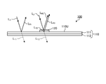
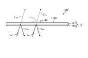
- 4 and 5 are cross-sectional views schematically showing the display medium 100 according to the first embodiment of the present invention. 4 and 5 show schematically the paths of light reflected by the polarizing separation layer 111 and the first reflection layer 120. In the actual display medium 100, various light absorptions and reflections may occur in addition to those described below, but in the following description, the main light paths will be schematically described for convenience of explaining the action. ..
- FIG. 4 shows a case where the first reflective layer 120 side of the display medium 100 is irradiated with irradiation light LI1 such as unpolarized light including both right-handed circularly polarized light and left-handed circularly polarized light.
- irradiation light LI1 such as unpolarized light including both right-handed circularly polarized light and left-handed circularly polarized light.
- the polarization separation layer 111 and the retardation layer 112 are arranged in this order, so that the irradiation light LI1 enters the polarization separation layer 111.
- Some of the irradiated light L I1 is reflected by the polarization separating layer 111 as circularly polarized light L R1 rotational direction D A.
- Circularly polarized light L R1 other light L T1 reflected is transmitted through the polarization separating layer 111, further passes through the retardation layer 112, exiting to the outside of the display medium 100. Since circularly polarized light L R1 by the polarization separating layer 111 is reflected, at the time just after passing through the polarization separating layer 111, some or all of the light L T1 transmitted through the polarization separating layer 111, the direction of rotation D A reverse It is circularly polarized light in the direction of rotation.
- the first reflection layer 120 in the area where the first reflection layer 120 is provided, the first reflection layer 120, the polarization separation layer 111, and the retardation layer 112 are arranged in this order, so that the irradiation light LI1 can be obtained. It enters the first reflective layer 120. Some of the circularly polarized light included in the irradiation light L I1 is reflected by the first reflective layer 120 as a circularly polarized light L R2 in the rotating direction D B1. Light L T2 other than circularly polarized light L R2 that is reflected and enters the polarization separation layer 111.
- the light L T2 which enters the polarization separating layer 111 may include circularly polarized light L R3 in the rotational direction D A which can be reflected. Therefore, part of the light L T2 may be reflected by the polarization separating layer 111 as circularly polarized light L R3 rotational direction D A. These reflected circularly polarized light L R2 and L R3 other light L T3 is transmitted through the polarization separating layer 111, further passes through the retardation layer 112, exiting to the outside of the display medium 100.
- the circular polarization of some or all contained in the light L T3 exiting from the display medium 100 passes through the retardation layer 112, the same rotational direction as the rotational direction D A It is circularly polarized.
- the first reflective layer 120 side of the display medium 100 when the first reflective layer 120 side of the display medium 100 is illuminated with the irradiation light LI1 including both right circular polarization and left circular polarization, strong light reflection occurs in the first reflective layer 120.
- the observer can visually recognize the circularly polarized light LR2 reflected by the first reflection layer 120. Therefore, an observer observing from the first reflective layer 120 side of the display medium 100 can visually recognize the image of the first reflective layer 120 as shown in FIG.
- FIG. 5 shows a case where the side of the display medium 100 opposite to the first reflective layer 120 is irradiated with irradiation light LI2 such as unpolarized light containing both right-handed circularly polarized light and left-handed circularly polarized light.
- irradiation light LI2 such as unpolarized light containing both right-handed circularly polarized light and left-handed circularly polarized light.
- the irradiation light LI2 passes through the retardation layer 112 of the multilayer base material 110 and then enters the polarization separation layer 111.
- a part of the irradiation light LI2 is reflected by the polarization separation layer 111 as circularly polarized light LR4 in the rotation direction DA, and the rotation direction is reversed by passing through the retardation layer 112.
- the rotation direction of a part or all of the circularly polarized light contained in the light LT4 transmitted through the polarization separation layer 111 is reflected by the polarization separation layer 111. made in the direction of rotation D a and opposite circular polarization L R4.
- the rotational direction D B1 of the circularly polarized light first reflective layer 120 can be reflected as a reflection layer according to the present embodiment is the same as the rotational direction D A circularly polarized light L R4 which are reflected by the polarization separating layer 111 ..
- the light L T4 entering the first reflection layer 120 is either the first reflective layer 120 does not include circularly polarized light rotating direction D B1 which can be reflected, contains only a small amount. Therefore, all or most of the light LT4 is not reflected by the first reflective layer 120. Therefore, the light L T5 of all or most of the light L T4 exits from the display medium 100 passes through the first reflective layer 120.
- the first reflective layer 120 can be visually recognized when observed from the first reflective layer side, but the first reflective layer 120 and When observed from the opposite side, the first reflective layer 120 cannot be visually recognized. Therefore, according to the display medium 100, the image of the display medium that is visually recognized when observed from the front surface and the image of the display medium that is visually recognized when observed from the back surface while the multilayer base material 110 is transparent or translucent. It is possible to have a specific display mode in which the above is different.
- an image of the display medium 100 and a display article (the present embodiment) that are visually recognized according to the orientation of the front and back of the display medium 100. (Not shown) can be different from each other.
- the first reflective layer 120 as the reflective layer is provided on the surface 110U of the multilayer base material 110 on the polarization separation layer side, but the reflective layer is located at the position of the multilayer base material 110. It may be formed on the surface on the side of the retardation layer.
- a second reflective layer as a reflective layer is provided on the surface of the multilayer base material 110 on the retardation layer side.
- FIG. 6 is a cross-sectional view schematically showing the display medium 200 according to the second embodiment of the present invention.
- FIG. 7 is a schematic plan view of the display medium 200 according to the second embodiment of the present invention as viewed from one side (the side opposite to the side on which the second reflective layer 220 is provided).
- FIG. 8 is a schematic plan view of the display medium 200 according to the second embodiment of the present invention as viewed from the other side (the side on which the second reflective layer 220 is provided).
- the display medium 200 has a multilayer base material 110 including a polarizing separation layer 111 and a retardation layer 112, and a position of the multilayer base material 110.
- a second reflective layer 220 as a reflective layer provided on the surface 110D on the differential layer side is provided.
- the multilayer base material 110 included in the display medium 200 according to the second embodiment can be the same as that included in the display medium 100 according to the first embodiment.
- the display medium 200 according to the second embodiment uses the same multi-layer base material 110 as described in the first embodiment, the same effect as described in the first embodiment can be obtained.
- the second reflective layer 220 as a reflective layer is provided on the surface 110D on the retardation layer side of the multilayer base material 110.
- the second reflective layer 220 may be provided directly or indirectly on the surface 110D of the multilayer base material 110, as in the case of the first reflective layer 120 described in the first embodiment. ..
- the second reflective layer 220 may be provided on a part of the surface 110D of the multilayer base material 110, or may be provided on the entire surface 110D. Normally, when viewed from the thickness direction, the second reflective layer 220 overlaps both the polarization separation layer 111 and the retardation layer 112 of the multilayer base material 110, like the first reflective layer 120 described in the first embodiment. It is provided in. In the present embodiment, the second reflective layer 220 having the planar shape of the letter “E” will be described as an example. In this example, the entire second reflective layer 220 overlaps a part of the polarization separation layer 111 and a part of the retardation layer 112 of the multilayer base material 110 when viewed from the thickness direction.
- the second reflective layer 220 has a circular polarization separation function. Therefore, the second reflective layer 220 reflects the circular polarization in one of the rotation directions D B2 in the wavelength range in which the circular polarization separation function can be exhibited, and transmits the circular polarization in the rotation direction opposite to the rotation direction D B2. Can be made to.
- the wavelength range in which the second reflective layer 220 can exhibit the circular polarization separation function may be appropriately referred to as the “second reflected wavelength range”.
- the range of reflectance of the second reflective layer 220 for non-polarization in the second reflection wavelength range is the same as the range of reflectance of the first reflective layer 120 for non-polarization in the first reflection wavelength range described in the first embodiment. It is possible.
- the second reflection wavelength range of the second reflection layer 220 usually overlaps with the polarization separation wavelength range of the polarization separation layer 111 included in the multilayer base material 110.
- a part of the second reflection wavelength range and a part of the polarization separation wavelength range may overlap, and the whole second reflection wavelength range and a part of the polarization separation wavelength range may overlap.
- a part of the two reflection wavelength range and the entire polarization separation wavelength range may overlap, or the entire second reflection wavelength range and the entire polarization separation wavelength range may overlap.
- it is preferable that the second reflection wavelength range is within the polarization separation wavelength range because the entire second reflection wavelength range overlaps with a part or all of the polarization separation wavelength range.
- the lower limit of the second reflection wavelength range is equal to or higher than the lower limit of the polarization separation wavelength range
- the upper limit of the second reflection wavelength range is equal to or lower than the upper limit of the polarization separation wavelength range.
- Rotational direction D B2 of the circularly polarized light by the second reflection layer 220 can be reflected, the polarization separating layer 111 is set to reverse the rotational direction D A circularly polarized light can be reflected. Therefore, when light enters the second reflective layer 220 through the multilayer base material 110, at least a part of the circularly polarized light (specifically, the circularly polarized light in the polarization separation wavelength range) contained in the light. the rotational direction D C, the circular polarization direction of rotation D B2 of the second reflective layer 220 can be reflected is reversed. Therefore, the second reflective layer 220 can hardly or hardly reflect the light that has passed through the multilayer base material 110 and enters the second reflective layer 220.
- Such a second reflective layer 220 may be a cholesteric resin layer like the first reflective layer 120 described in the first embodiment, but is preferably a layer containing flakes of the cholesteric resin.
- a layer containing cholesteric resin flakes is used as the second reflective layer 220, the same effect as described in the first embodiment can be obtained.
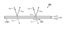
- 9 and 10 are cross-sectional views schematically showing the display medium 200 according to the second embodiment of the present invention.
- 9 and 10 show schematically the paths of light reflected by the polarizing separation layer 111 and the second reflection layer 220.
- various light absorptions and reflections may occur in addition to those described below, but in the following description, the main light paths will be schematically described for convenience of explaining the action. ..
- FIG. 9 shows a case where the display medium 200 is irradiated with irradiation light LI3 such as unpolarized light including both right-handed circularly polarized light and left-handed circularly polarized light on the side opposite to the second reflective layer 220.
- irradiation light LI3 such as unpolarized light including both right-handed circularly polarized light and left-handed circularly polarized light on the side opposite to the second reflective layer 220.
- the polarization separation layer 111 and the retardation layer 112 are arranged in this order, so that the irradiation light LI3 enters the polarization separation layer 111.
- Some of the irradiated light L I3 is reflected by the polarization separating layer 111 as circularly polarized light L R5 in the rotating direction D A.
- the reflected circularly polarized light L R5 other light L T6 is transmitted through the polarization separating layer 111, further passes through the retardation layer 112, exiting to the outside of the display medium 200. Since circularly polarized light L R5 by the polarization separating layer 111 is reflected, at the time just after passing through the polarization separating layer 111, some or all of the light L T6 transmitted through the polarization separating layer 111, the direction of rotation D A reverse It is circularly polarized light in the direction of rotation.
- the polarization separation layer 111, the retardation layer 112, and the second reflection layer 220 are arranged in this order, so that the second reflection layer 220 is arranged.
- a part of the irradiation light L I3 is reflected by the polarization separating layer 111 as circularly polarized light L R5 in the rotating direction D a, reflected circularly polarized light L R5 other light L T6 polarization separating It is transparent to the layer 111 and the retardation layer 112.
- the light LT6 transmitted through the retardation layer 112 then enters the second reflection layer 220.
- the direction of rotation of some or all of the circularly polarized light contained in the light L T6 after passing through the retardation layer 112 is the same as the rotational direction D A circularly polarized light L R5 reflected by the polarization separating layer 111 .
- the rotational direction D B2 of the circularly polarized light by the second reflection layer 220 as a reflection layer according to the present embodiment can be reflected is the direction of rotation D A and opposite circular polarization L R5 reflected by the polarization separating layer 111 .. Therefore, the light L T6 entering the second reflective layer 220, or the second reflective layer 220 does not include circularly polarized light in the direction of rotation D B2 which can reflect, contain only a small amount.
- the light LT6 is not reflected by the second reflective layer 220. Since the direction of rotation D A circularly polarized light by the second reflection layer 220 and the rotational direction D B2 of the circularly polarized light can reflect the polarization separating layer 111 may be reflected is reversed, as in the area where the second reflecting layer 220 is not provided , even in areas where the second reflecting layer 220 is provided, some or all of the light L T7 leaving the display medium 200 passes through the second reflective layer 220, a circularly polarized light in the same rotational direction as the rotational direction D a ing.
- FIG. 10 shows a case where the second reflective layer 220 side of the display medium 200 is irradiated with irradiation light LI4 such as unpolarized light including both right-handed circularly polarized light and left-handed circularly polarized light.
- irradiation light LI4 such as unpolarized light including both right-handed circularly polarized light and left-handed circularly polarized light.
- the irradiation light LI4 passes through the retardation layer 112 of the multilayer base material 110 and then enters the polarization separation layer 111.
- Some of the irradiated light L I4 is reflected by the polarization separating layer 111 as circularly polarized light L R6 rotational direction D A, the direction of rotation is reversed by passing through the retardation layer 112.
- the irradiation light LI4 enters the second reflection layer 220.
- a part of the circularly polarized light contained in the irradiation light LI4 is reflected by the second reflecting layer 220 as the circularly polarized light LR7 in the rotation direction D B2 .
- Light L T9 other than circularly polarized light L R7 reflected is transmitted through the retardation layer 112, it enters the polarization separating layer 111.
- the light L T9 entering the polarization separating layer 111 may include circularly polarized light L R8 rotational direction D A which can be reflected.
- part of the light L T9 may be reflected by the polarization separating layer 111 as circularly polarized light L R8 rotational direction D A.
- These reflected circularly polarized light L R7 and L R8 other light L T10 is transmitted through the polarization separating layer 111, exiting to the outside of the display medium 200.
- the light L T10 is emitted from the display medium 200 after passing through the polarization separation layer 111. Therefore, the light L transmitted through the polarization separation layer 111 and emitted from the display medium 200.
- some or all of the T10 has a direction of rotation D a reverse rotation direction of the circularly polarized light.
- the second reflective layer 220 side of the display medium 200 when the second reflective layer 220 side of the display medium 200 is illuminated with the irradiation light LI4 including both right circular polarization and left circular polarization, strong light reflection occurs in the second reflective layer 220.
- the observer can visually recognize the circularly polarized light LR7 reflected by the second reflective layer 220. Therefore, the observer observing from the second reflective layer 220 side of the display medium 200 can visually recognize the image of the second reflective layer 220 as shown in FIG.
- the second reflective layer 220 can be visually recognized when observed from the second reflective layer 220 side, but the second reflective layer 220 is visible.
- the second reflective layer 220 cannot be visually recognized when observed from the opposite side. Therefore, according to the display medium 200, the image of the display medium observed from the front surface and the image of the display medium observed from the back surface while the multilayer base material 110 is transparent or translucent. It is possible to have a specific display mode in which the above is different. Further, according to the display medium 200 according to the present embodiment, the same advantages as the display medium 100 described in the first embodiment can be obtained.
- first reflective layer 120 or the second reflective layer 220 as a reflective layer is provided on one surface 110U or 110D of the multilayer base material 110 is shown, but the display medium. May be provided with reflective layers on both sides thereof.
- first reflective layer and the second reflective layer as the reflective layers are provided on both surfaces of the multilayer base material 110 will be described.
- FIG. 11 is a cross-sectional view schematically showing the display medium 300 according to the third embodiment of the present invention.
- FIG. 12 is a schematic plan view of the display medium 300 according to the third embodiment of the present invention as viewed from one side (the side on which the first reflective layer 120 is provided).
- FIG. 13 is a schematic plan view of the display medium 300 according to the third embodiment of the present invention as viewed from the other side (the side on which the second reflective layer 220 is provided).
- the display medium 300 includes a multilayer base material 110 including a polarization separation layer 111 and a retardation layer 112, and polarization of the multilayer base material 110.
- the first reflective layer 120 as a reflective layer provided on the surface 110U on the separation layer side
- the second reflective layer 220 as a reflective layer provided on the surface 110D on the retardation layer side of the multilayer base material 110.
- the multilayer base material 110 included in the display medium 300 according to the third embodiment can be the same as that included in the display medium 100 according to the first embodiment.
- the same display medium 300 as described in the first embodiment is used as the multilayer base material 110 in the display medium 300 according to the third embodiment, the same effect as described in the first embodiment can be obtained.
- the first reflective layer 120 included in the display medium 300 according to the third embodiment may be the same as that included in the display medium 100 according to the first embodiment.
- the display medium 300 according to the third embodiment uses the same first reflective layer 120 as described in the first embodiment, the same effect as described in the first embodiment can be obtained.
- the second reflective layer 220 included in the display medium 300 according to the third embodiment may be the same as that included in the display medium 200 according to the second embodiment.
- the display medium 300 according to the third embodiment uses the same second reflective layer 220 as described in the second embodiment, the same effect as described in the second embodiment can be obtained.
- the first reflective layer 120 of the display medium 300 is the first reflection of the display medium 300 under irradiation light including both right-handed circularly polarized light and left-handed circularly polarized light by the same mechanism as described in the first embodiment. Although it can be visually recognized by an observer observing from the layer 120 side (FIG. 12), it can be visually recognized by an observer observing from the second reflection layer 220 side as the side opposite to the first reflection layer 120 of the display medium 300. Cannot be done (Fig. 13).
- the second reflective layer 220 of the display medium 300 is the second reflective layer 220 of the display medium 300 under irradiation light including both right-handed circularly polarized light and left-handed circularly polarized light by the same mechanism as described in the second embodiment.
- the display medium 300 while the multilayer base material 110 is transparent or translucent, the image of the display medium that is observed and visually recognized from the front surface and the image of the display medium that is visually recognized from the back surface are visually recognized. It is possible to have a specific display mode in which the image of the display medium is different from that of the display medium. Further, according to the display medium 300 according to the present embodiment, the same advantages as those of the display media 100 and 200 described in the first embodiment and the second embodiment can be obtained.
- the shape, size, and material of the reflective layers, and the wavelength and reflectance of the circularly polarized light reflected by the reflective layer are determined. , It may be the same or different.
- the display medium is not limited to that described in the first to third embodiments described above.
- the display medium may further include any element in combination with the reflective layers such as the multilayer base material 110, the first reflective layer 120, and the second reflective layer 220 described above.
- the display medium may include any layer having a circular polarization separation function on the surfaces 110U and 110D of the multilayer base material 110 in addition to the first reflective layer 120 and the second reflective layer 220.
- the polarization separation layer side surface 110U of the multi layer substrate 110, and reflected circularly polarized light rotation of the circularly polarized light is polarized light separation layer 111 can reflect the direction D A reverse rotation direction D E1, the rotation it may comprise a first optional layer that can transmit circularly polarized light of the opposite rotational direction to the direction D E1.
- a second arbitrary layer capable of transmitting circularly polarized light in a rotation direction opposite to that of the rotation direction DE2 may be provided.
- Any of these layers can be formed, for example, as a layer of cholesteric resin, a layer containing flakes of cholesteric resin, and the like. Any of these layers can usually be seen both from the front side and from the back side.
- the display medium may include an arbitrary non-chiral layer containing a colorant such as a pigment and a dye that does not have a circular polarization separation function.
- This non-chiral layer may be provided on the surface 110U on the polarization separation layer side of the multilayer base material 110, or may be provided on the surface 110D on the retardation layer side.
- This non-chiral layer can usually be visually recognized both when observed from the front surface and when observed from the back surface.
- the display medium may be provided with an adhesive layer for bonding the above-mentioned layers to each other.
- the display medium may include an adhesive layer between the multilayer base material 110 and the first reflective layer 120, and adheres between the multilayer base material 110 and the second reflective layer 220. It may have layers.
- the adhesive layer preferably has a small in-plane retardation, like any layer that the multilayer substrate 110 may have.
- the display medium may include a cover layer that protects each of the above-mentioned layers. It is preferable that these cover layers are provided outside the above-mentioned layers.
- the display medium may include a cover layer, a second reflective layer, a multilayer base material, a first reflective layer, and a cover layer in this order in the thickness direction.
- a cover layer can be formed of a transparent material, for example, a resin.
- the display medium may include any layer having a small in-plane retardation between the above-mentioned layers and as the outermost layer of the display medium as long as the effect of the present invention is not significantly impaired.
- Any layer having such a small in-plane retardation may be hereinafter referred to as a "low Re layer".
- the specific in-plane retardation of this low Re layer is usually 0 nm or more and 5 nm or less.
- the positions where the low Re layer is provided are, for example, the positions of the first reflective layer opposite to the multilayer base material, the positions between the first reflective layer and the multilayer substrate, the polarization separation layer and the retardation layer.
- the position between, the position between the multi-layer base material and the second reflective layer, the position of the second reflective layer opposite to the multi-layer base material, and the like are not limited thereto.
- the low Re layer preferably has high light transmittance, and the total light transmittance of the low Re layer is preferably 80% or more, more preferably 85% or more.
- Examples of such a low Re layer material include hard polyvinyl chloride, soft polyvinyl chloride, acrylic resin, glass, polycarbonate (PC), polyethylene terephthalate (PET), and the like.
- the specific material can be appropriately selected according to the application of the display medium, the required texture, durability, and mechanical strength.
- the display medium described above can be used as a display set in combination with a display article for observation through the display medium.
- the display article to be combined with the display medium includes a base article and a display layer provided on the base article.
- Display layer is a layer having a circularly polarized light separating function to reflect circularly polarized light of one rotational direction D D, and the direction of rotation D D can transmit circularly polarized light of the opposite rotational direction. Therefore, the direction of rotation D part or all of the circular polarization of D is the reflection from the display layers, a multilayer substrate of the display medium can be transmitted in one of the following order (i) and (ii), the other order Cannot be transparent.
- the order of the polarization separation layer and the retardation layer (Ii) The order of the retardation layer and the polarization separation layer.
- the image of the display article visually recognized through the display medium can be different depending on the orientation of the front and back of the display medium.
- the display medium itself can have a different image of the display medium visually recognized depending on the orientation of the front and back of the display medium.
- FIG. 14 is a cross-sectional view schematically showing the display set 400 according to the fourth embodiment of the present invention.
- the display set 400 according to the fourth embodiment of the present invention includes a display medium 300 and a display article 500.
- the display set 400 including the display medium 300 described in the third embodiment will be described as an example.
- FIG. 15 is a cross-sectional view schematically showing a display article 500 included in the display set 400 according to the fourth embodiment of the present invention.
- FIG. 16 is a plan view schematically showing a display article 500 included in the display set 400 according to the fourth embodiment of the present invention.
- the display article 500 includes a base article 510, and a first display layer 520 and a second display layer 530 as display layers provided on the base article 510.
- the base article 510 is an article provided with a display layer such as a first display layer 520 and a second display layer 530, and the range thereof is not limited.
- Examples of the base article 510 include cloth products such as clothing; leather products such as bags and shoes; metal products such as screws; paper products such as price tags; plastic products such as cards and plastic banknotes; rubber products such as tires; However, it is not limited to these examples.
- Both the first display layer 520 and the second display layer 530 as the display layer have a circular polarization separation function.
- the rotation direction D D1 of the circular polarization that can be reflected by the first display layer 520 and the rotation direction D D2 of the circular polarization that can be reflected by the second display layer 530 are opposite.
- the first display layer 520 in the wavelength range capable of exhibiting the circularly polarized light separating function, the circularly polarized light can reflect the polarization separating layer 111 included in the display medium 300 in the rotational direction D A in the same rotational direction D D1 reflects circularly polarized light can be transmitted through the circularly polarized light of reverse rotation direction to the rotation direction D D1.
- the second display layer 530 in the wavelength range capable of exhibiting the circularly polarized light separation function, reflects the circularly polarized light rotation of the circularly polarized light is polarized light separation layer 111 can reflect the direction D A reverse rotation direction D D2, its Circularly polarized light in the direction opposite to the direction of rotation D D2 can be transmitted.
- the wavelength range in which the first display layer 520 can exert the circular polarization separation function may be appropriately referred to as the "first display wavelength range”.
- the wavelength range in which the second display layer 530 can exhibit the circular polarization separation function may be appropriately referred to as a "second display wavelength range”.
- the first display wavelength range and the second display wavelength range may be collectively referred to as simply "display wavelength range”.
- the range of reflectance for unpolarized light of the first display layer 520 and the second display layer 530 in the display wavelength range can be the same as the range of reflectance for non-polarized light of the polarization separation layer 111 in the polarization separation wavelength range.
- the reflectance of the first display layer 520 and the reflectance of the second display layer 530 may be the same or different.
- the display wavelength range of the first display layer 520 and the second display layer 530 usually overlaps with the polarization separation wavelength range of the polarization separation layer 111 included in the display medium 300.
- a part of the display wavelength range and a part of the polarization separation wavelength range may overlap, or the whole display wavelength range and a part of the polarization separation wavelength range may overlap, and one of the display wavelength ranges.
- the unit and the entire polarization separation wavelength range may overlap, or the entire display wavelength range and the entire polarization separation wavelength range may overlap. Above all, it is preferable that the display wavelength range is within the polarization separation wavelength range because the entire display wavelength range overlaps with a part or all of the polarization separation wavelength range.
- the lower limit of the display wavelength range is equal to or higher than the lower limit of the polarization separation wavelength range
- the upper limit of the display wavelength range is equal to or lower than the upper limit of the polarization separation wavelength range.
- Such a first display layer 520 and a second display layer 530 may be a cholesteric resin layer like the first reflective layer 120 described in the first embodiment, but are layers containing cholesteric resin flakes. Is preferable.
- the first display layer 520 having the planar shape of the letter "I” and the second display layer 530 having the planar shape of the letter “S” are provided on the sheet-shaped base article 510.
- Article 500 will be described as an example.
- the display article 500 may be provided with an arbitrary non-chiral layer 540 containing a colorant such as a pigment and a dye having no circular polarization separation function, if necessary.
- a colorant such as a pigment and a dye having no circular polarization separation function
- the non-chiral layer 540 having the planar shape of the letter “M” will be described as an example.
- the display set 400 has a combination of the display medium 300 and the display article 500 having the above-described configuration. Therefore, the observer can visually recognize the image described below.
- the observer usually observes the display set 400 from above in the figure. Therefore, the observer observes the display medium 300 from the first reflective layer 120 side, and at the same time, observes the display article 500 through the display medium 300.
- FIG. 17 is a plan view schematically showing an image visually recognized when the display set 400 shown in FIG. 14 is observed from above in the drawing.
- the image visually recognized by the observer who observes the display set 400 as described above includes the first reflective layer 120 of the display medium 300, the first display layer 520 of the display article 500, and non-chiral.
- the layer 540 appears, but the second reflective layer 220 of the display medium 300 and the second display layer 530 of the display article 500 do not appear.
- the mechanism by which such an image is visually recognized is as follows.
- the polarization separation layer 111, the retardation layer 112, and the display article 500 are arranged in this order in the thickness direction of the display medium 300. Therefore, the irradiation light irradiated to the display medium 300 enters the display article 500 after a part of the circularly polarized light is reflected by the polarization separating layer 111 and the light other than the reflected circularly polarized light passes through the retardation layer 112. To do.
- the light L T1 of which is the same rotational direction of the circularly polarized light and the direction of rotation D A circularly polarized light reflected by the polarization separation layer 111 (FIG. 4 and L T3, and, referring to the light L T6 and L T7 in FIG. 9).
- the first display layer 520 may reflect circularly polarized light in the direction of rotation D A in the same rotational direction D D1, the light that enters the display article 500 is transmitted through the display medium 300, it produces a large reflection. Since the reflected light is circularly polarized light in the rotation direction D D1 , the rotation direction is reversed by passing through the retardation layer 112, and the light can be transmitted through the polarization separation layer 111. Therefore, since the strong light reflected by the first display layer 520 can pass through the display medium 300, the observer can visually recognize the image of the first display layer 520.
- the second display layer 530 may reflect circularly polarized light in the direction of rotation D A reverse rotation direction D D2, the light that enters the display article 500 is transmitted through the display medium 300, a weak reflection or no reflection .. Further, even if light is reflected by the second display layer 530, the reflected light is circularly polarized light in the rotation direction D D2 , so that the rotation direction is reversed by passing through the retardation layer 112. , Part or all is reflected by the polarization separation layer 111. Therefore, since there is no or weak light that can be reflected by the second display layer 530 and transmitted through the display medium 300, the observer cannot visually recognize the image of the second display layer 530.
- the non-chiral layer 540 light reflection occurs regardless of the polarization state of the light entering the display article 500. Therefore, since a part or the whole of the reflected light can pass through the display medium 300, the observer can visually recognize the image of the non-chiral layer 540.
- the observer can visually recognize the image of the first reflection layer 120 observed without passing through the multilayer base material 110, but the multilayer base material 110 The image of the second reflective layer 220 observed through is not visible.
- the observer can see the image shown by the first reflective layer 120 (letter "B"), the image shown by the first display layer 520 (letter “I”), and the non-chiral layer.
- the layer represented by 540 (letter "M") can be visually recognized, but the image of the second reflection layer 220 and the image of the second display layer 530 cannot be visually recognized.
- FIG. 18 is a cross-sectional view schematically showing the display set 400 according to the fourth embodiment of the present invention.
- the display medium 300 and the display article 500 are overlapped with the surface 110U on the polarization separation layer 111 side of the multilayer base material 110 facing the display article 500.
- the observer usually observes the display set 400 from above in the figure. Therefore, the observer observes the display medium 300 from the second reflective layer 220 side, and at the same time, observes the display article 500 through the display medium 300.
- FIG. 19 is a plan view schematically showing an image visually recognized when the display set 400 shown in FIG. 18 is observed from above in the drawing.
- the image visually recognized by the observer who observes the display set 400 as described above includes the second reflective layer 220 of the display medium 300, the second display layer 530 of the display article 500, and non-chiral.
- the layer 540 appears, but the first reflective layer 120 of the display medium 300 and the first display layer 520 of the display article 500 do not appear.
- the mechanism by which such an image is visually recognized is as follows.
- the retardation layer 112, the polarization separation layer 111, and the display article 500 are arranged in this order in the thickness direction of the display medium 300. Therefore, the irradiation light irradiated to the display medium 300 passes through the retardation layer 112, and after a part of the circular polarization is reflected by the polarization separation layer 111, it enters the display article 500. Some or all of the light entering into such display article 500, the has become the the circular polarization direction of rotation D A reverse rotation direction of the circularly polarized light reflected by the polarization separating layer 111 (FIG. 5 light L T4 and L T5, as well as reference light L T8 and L T10 in FIG. 10).
- the first display layer 520 may reflect circularly polarized light in the direction of rotation D A in the same rotational direction D D1, the light that enters the display article 500 is transmitted through the display medium 300, a weak reflection or no reflection. Further, even if light is reflected by the first display layer 520, the reflected light is circularly polarized light in the rotation direction DD1 , so that part or all of the reflected light is reflected by the polarization separation layer 111. Therefore, since there is no or weak light that can be reflected by the first display layer 520 and transmitted through the display medium 300, the observer cannot visually recognize the image of the first display layer 520.
- the second display layer 530 may reflect circularly polarized light in the direction of rotation D A reverse rotation direction D D2, the light that enters the display article 500 is transmitted through the display medium 300, it produces a large reflection. Since the reflected light is circularly polarized light in the rotation direction D D2 , it can pass through the polarization separation layer 111. Therefore, since the strong light reflected by the second display layer 530 can pass through the display medium 300, the observer can visually recognize the image of the second display layer 530.
- the non-chiral layer 540 light reflection occurs regardless of the polarization state of the light entering the display article 500. Therefore, since a part or the whole of the reflected light can pass through the display medium 300, the observer can visually recognize the image of the non-chiral layer 540.
- the observer can visually recognize the image of the second reflective layer 220 observed without passing through the multilayer base material 110, but the multilayer base material 110 The image of the first reflective layer 120 observed through is not visible.
- the observer can see the image shown by the second reflective layer 220 (letter "E"), the image shown by the second display layer 530 (letter "S”), and the non-chiral layer.
- the layer represented by 540 (letter "M") can be visually recognized, but the image of the first reflection layer 120 and the image of the first display layer 520 cannot be visually recognized.
- the image visually recognized can be different depending on the orientation of the display medium 300. Therefore, by combining different images in this way, it is possible to realize a new display mode that has not existed in the past, and it is possible to create a complicated and highly flexible design.
- the multilayer base material 110 of the display medium 300 is transparent or translucent, as described above, depending on the orientation of the display medium 300. Since the difference in image can be a display that is unexpected to a general observer, it can be expected to have a great impact on the observer.
- the display article 500 including both the first display layer 520 and the second display layer 530 has been described as an example, but at least one of the first display layer 520 and the second display layer 530 has been described.
- a display article containing the above may be used.
- a display article having one or more first display layers 520 and not having a second display layer 530 may be used.
- a display article having one or more second display layers 530 and not having the first display layer 520 may be used.
- the base film was peeled off from the multi-layer film to obtain a cholesteric resin layer.
- the reflectance when unpolarized light (wavelength 400 nm to 800 nm) was incident on the cholesteric resin layer was measured using an ultraviolet-visible spectrophotometer (“UV-Vis 550” manufactured by JASCO Corporation).
- the in-plane retardation was measured at a measurement wavelength of 590 nm using a phase difference meter (“Axoscan” manufactured by Axometrics).
- a base film As a base film, a long polyethylene terephthalate film (“A4100” manufactured by Toyobo Co., Ltd .; thickness 100 ⁇ m) was prepared. This base film was attached to the feeding portion of the film transport device, and the following operations were performed while transporting the base film in the long direction.
- A4100 manufactured by Toyobo Co., Ltd .; thickness 100 ⁇ m
- the surface of the base film was subjected to a rubbing treatment in a long direction parallel to the transport direction.
- the liquid crystal composition was applied to the surface of the base film subjected to the rubbing treatment using a die coater to form a layer of the liquid crystal composition.
- the layer of the liquid crystal composition was subjected to an orientation treatment by heating at 120 ° C. for 4 minutes.
- the layer of the liquid crystal composition was subjected to a broadband treatment.
- the reflection band was controlled to a desired bandwidth by alternately repeating weak ultraviolet irradiation of 5 mJ / cm 2 to 30 mJ / cm 2 and heating treatment of 100 ° C. to 120 ° C. a plurality of times.
- the layer of the liquid crystal composition was irradiated with ultraviolet rays of 800 mJ / cm 2 to cure the layer of the liquid crystal composition.
- a multi-layer film including a base film and a layer of cholesteric resin was obtained.
- the reflectance of the cholesteric resin layer of this multi-layer film was measured by the above-mentioned measuring method.
- the cholesteric resin layer had a wavelength range from 450 nm to 700 nm in which the reflectance with respect to unpolarized light was 40% or more.
- the reflectance of the cholesteric resin layer of this multi-layer film was measured by the above-mentioned measuring method.
- the cholesteric resin layer had a wavelength range from 450 nm to 700 nm in which the reflectance with respect to unpolarized light was 40% or more.
- the cholesteric resin layer was peeled off from the multi-layer film thus obtained and pulverized to obtain flakes. 10 parts of these flakes were mixed with 85 parts of screen ink (“No. 2500 medium” manufactured by Jujo Chemical Co., Ltd.) and 5 parts of a special diluent (Tetron standard solvent) for the screen ink to obtain an ink.
- a base film containing a norbornene-based polymer as a cyclic structure-containing polymer (“ZEONOR film” manufactured by Nippon Zeon Co., Ltd .; a film produced by extrusion molding; an unstretched product) was prepared. This base film was stretched 3.9 times in one direction at a stretching temperature of 130 ° C. to obtain a retardation film. The thickness of this retardation film was 38 ⁇ m, and the in-plane retardation was 280 nm.
- FIG. 20 is a cross-sectional view schematically showing the display set 1 manufactured in the first embodiment.
- the display set 1 manufactured in the first embodiment includes the display medium 10 and the display article 20.
- Display medium 10 the polarization separation layer 11 and the multilayer substrate 13 with a phase difference layer 12; character layer B R as a first reflective layer provided on the surface of the polarization separation layer side of the multilayer substrate 13; and includes a character layer E L as a second reflective layer provided on the surface of the retardation layer side of the multilayer substrate 13.
- the display medium 10 produced in Example 1 contained a support layer and an adhesive, but these are not shown in FIG. 20.
- a method of manufacturing the display set 1 will be described.
- the cholesteric resin layer of the multi-layer film produced in Production Example 1 and the optically isotropic support film (polyvinyl chloride film) are bonded to each other via an adhesive to form a base film of the multi-layer film. It peeled off.
- the surface of the cholesteric resin layer that appeared by peeling off the base film and the retardation film produced in Production Example 4 were bonded to each other via an adhesive.
- the retardation layer 12 as the retardation film were provided in this order to obtain a multilayer base material 13.
- the display medium 10 was turned over and placed on the display article 20, and the display set 1 was observed again.
- the character layer S L, the character layer E L and character layer M X has been visible, character layer I R and the character layer B R was not visible.
- Example 1 The results of Example 1 are summarized in Table 1 below.
- “Positive” The rotation direction of the circularly polarized light that can reflect the character layer and the rotation direction of the circularly polarized light that can reflect the polarization separation layer are the same.
- “Reverse” The rotation direction of circularly polarized light that can reflect the character layer and the rotation direction of circularly polarized light that can reflect the polarization separation layer are opposite.
- “Non” The character layer does not have a circular polarization separation function.
- FIG. 21 is a cross-sectional view schematically showing the display set 2 manufactured in the second embodiment.
- the display set 2 manufactured in the second embodiment includes the display medium 30 and the display article 20.
- the display article 20 is the same as that of the first embodiment.
- the display medium 30, except that the character layer E R instead of the character layer E L is formed is the same as the display medium 10 of Example 1.
- Character layer E R instead of the ink produced in Production Example 3, except for using ink prepared in Preparation Example 2 was formed in the same manner as the character layer E L formed in Example 1.
- the character layer E R corresponds to the second optional layer having flakes polarization separation layer 11 can reflect circularly polarized light in the same rotational direction as the rotational direction of the circularly polarized light can be reflected.
- the display medium 30 was turned over and placed on the display article 20, and the display set 2 was observed again.
- the character layer S L, the character layer E R and the character layer M X has been visible, character layer I R and the character layer B R was not visible.
- Example 2 The results of Example 2 are summarized in Table 2 below. In the column of "direction of circularly polarized light that can be reflected” in Table 2, the meanings of the abbreviations “positive”, “reverse” and “non” are the same as in Table 1.
- FIG. 22 is a cross-sectional view schematically showing the display set 3 manufactured in Comparative Example 1.
- the display set 3 manufactured in Comparative Example 1 includes a display medium 40 and a display article 20.
- the display article 20 is the same as that of the first embodiment.
- the display medium 40 is a phase difference layer 12 without, as well, except that the character layer E R instead of the character layer E L is formed is the same as the display medium 10 of Example 1.
- the display medium 40 was manufactured by the following procedure.
- the cholesteric resin layer of the multi-layer film produced in Production Example 1 and the optically isotropic support film (polyvinyl chloride film) are bonded to each other via an adhesive to form a base film of the multi-layer film. It peeled off.
- On the layer of cholesteric resin to print the letter "B” in the ink produced in Production Example 2, and dried to form a character layer B R.
- the support film to print the letter "E” in the ink produced in Production Example 2, and dried to form a character layer E R.
- the display medium 40 was turned over and placed on the display article 20, and the display set 3 was observed again.
- the character layer S L, the character layer E R and the character layer M X has been visible, character layer I R and the character layer B R was not visible.
- FIG. 23 is a cross-sectional view schematically showing the display set 4 manufactured in Comparative Example 2.
- the display set 4 manufactured in Comparative Example 2 includes a display medium 50 and a display article 20.
- the display article 20 is the same as that of the first embodiment.
- the display medium 50, except that the character layer E L instead of the character layer E R is formed is the same as the display medium 40 of Comparative Example 1.
- Character layer E L instead of the ink produced in Production Example 2, except for using an ink produced in Production Example 3 was formed in the same manner as the character layer E R formed in Comparative Example 1.
- the display medium 50 was turned over and placed on the display article 20, and the display set 4 was observed again.
- the character layer S L, the character layer E L and character layer M X has been visible, character layer I R and the character layer B R was not visible.
- FIG. 24 is a cross-sectional view schematically showing the display set 5 manufactured in Comparative Example 3.
- the display set 5 manufactured in Comparative Example 3 includes a display medium 60 and a display article 20.
- the display article 20 is the same as that of the first embodiment.
- the display medium 60 is the same as the display medium 10 of the first embodiment except that a circularly polarizing filter 63 including a linear polarizing element 61 and a quarter wave plate 62 in combination is provided instead of the multilayer base material 13. Is.
- the display medium 60 was manufactured by the following procedure.
- the slightly blackish circular polarization filter 63 described in Example 1 of Japanese Patent No. 5828182 was prepared.
- the circularly polarized light filter 63 was capable of transmitting right circularly polarized light and absorbing left circularly polarized light.
- On linear polarizer 61 of the circular polarizing filter 63 to print the letter "B" in the ink produced in Production Example 2, and dried to form a character layer B R.
- the 1/4-wave plate 62 to print the letter "E” in the ink produced in Production Example 3, and dried to form a character layer E L.
- the display medium 60 was turned over and placed on the display article 20, and the display set 5 was observed again.
- the character layer I R, a character layer S L, the character layer B R, a character layer E L and character layer M X both visible.
- FIG. 25 is a cross-sectional view schematically showing the display set 6 manufactured in Comparative Example 4.
- the display set 6 manufactured in Comparative Example 4 includes a display medium 70 and a display article 20.
- the display article 20 is the same as that of the first embodiment.
- the display medium 70, except that the character layer E R instead of the character layer E L is formed is the same as the display medium 60 of Comparative Example 3.
- Character layer E R instead of the ink produced in Production Example 3, except for using ink prepared in Preparation Example 2 was formed in the same manner as the character layer E L formed in Comparative Example 3.
- the display medium 70 was turned over and placed on the display article 20, and the display set 6 was observed again.
- the character layer I R, a character layer S L, the character layer B R, a character layer E R and the character layer M X both visible.
- Display medium 110 Multi-layer base material 110U Polarization separation layer side surface of multi-layer base material 110D Phase difference layer side surface of multi-layer base material 111 Polarization separation layer 112 Phase difference layer 120 First reflection layer 200 Display medium 220 No. Two reflective layers 300 Display medium 400 Display set 500 Display article 510 Underlay article 520 First display layer 530 Second display layer 540 Non-chiral layer
Landscapes
- Physics & Mathematics (AREA)
- General Physics & Mathematics (AREA)
- Optics & Photonics (AREA)
- Nonlinear Science (AREA)
- Chemical & Material Sciences (AREA)
- Crystallography & Structural Chemistry (AREA)
- Mathematical Physics (AREA)
- Engineering & Computer Science (AREA)
- Theoretical Computer Science (AREA)
- Marketing (AREA)
- Business, Economics & Management (AREA)
- Accounting & Taxation (AREA)
- Polarising Elements (AREA)
Priority Applications (4)
| Application Number | Priority Date | Filing Date | Title |
|---|---|---|---|
| CN202080051065.2A CN114096902B (zh) | 2019-07-31 | 2020-07-02 | 显示介质、显示物品以及显示套件 |
| JP2021536861A JP7639684B2 (ja) | 2019-07-31 | 2020-07-02 | 表示セット |
| US17/597,099 US12147115B2 (en) | 2019-07-31 | 2020-07-02 | Display medium, display product, and display set |
| EP20847513.7A EP4006889B1 (en) | 2019-07-31 | 2020-07-02 | Display medium and display set |
Applications Claiming Priority (2)
| Application Number | Priority Date | Filing Date | Title |
|---|---|---|---|
| JP2019141797 | 2019-07-31 | ||
| JP2019-141797 | 2019-07-31 |
Publications (1)
| Publication Number | Publication Date |
|---|---|
| WO2021020024A1 true WO2021020024A1 (ja) | 2021-02-04 |
Family
ID=74230577
Family Applications (1)
| Application Number | Title | Priority Date | Filing Date |
|---|---|---|---|
| PCT/JP2020/026100 Ceased WO2021020024A1 (ja) | 2019-07-31 | 2020-07-02 | 表示媒体、表示物品及び表示セット |
Country Status (5)
| Country | Link |
|---|---|
| US (1) | US12147115B2 (https=) |
| EP (1) | EP4006889B1 (https=) |
| JP (1) | JP7639684B2 (https=) |
| CN (1) | CN114096902B (https=) |
| WO (1) | WO2021020024A1 (https=) |
Cited By (1)
| Publication number | Priority date | Publication date | Assignee | Title |
|---|---|---|---|---|
| JPWO2022168699A1 (https=) * | 2021-02-05 | 2022-08-11 |
Citations (15)
| Publication number | Priority date | Publication date | Assignee | Title |
|---|---|---|---|---|
| JPS5828182B2 (ja) | 1975-09-26 | 1983-06-14 | 鹿島建設株式会社 | キセツタンクテイバンノボウシヨクコウホウ |
| JPS6142714B2 (https=) | 1978-04-03 | 1986-09-22 | Mitsubishi Electric Corp | |
| JP2000255200A (ja) * | 1999-03-05 | 2000-09-19 | Dainippon Printing Co Ltd | 偽造防止体及び偽造判別方法 |
| JP2001004829A (ja) * | 1999-06-22 | 2001-01-12 | Nippon Mitsubishi Oil Corp | コレステリック液晶性フィルム |
| JP3652476B2 (ja) | 1997-07-29 | 2005-05-25 | 日本発条株式会社 | 対象物の識別構造及びその構造が設けられた対象物 |
| JP2007057971A (ja) | 2005-08-25 | 2007-03-08 | Nippon Zeon Co Ltd | グリッド偏光フィルム |
| JP2007093675A (ja) * | 2005-09-27 | 2007-04-12 | Dainippon Printing Co Ltd | 真贋判定用媒体 |
| JP2009300662A (ja) | 2008-06-12 | 2009-12-24 | Toppan Printing Co Ltd | コレステリック液晶の螺旋ピッチを変える方法、それを使用したコレステリック液晶ディスプレイ用品 |
| JP2010111104A (ja) * | 2008-11-10 | 2010-05-20 | Nippon Zeon Co Ltd | 加飾シート及び成形体 |
| WO2014069515A1 (ja) | 2012-10-30 | 2014-05-08 | 日本ゼオン株式会社 | 液晶組成物、位相差板、画像表示装置、および光学異方性層の波長分散制御方法 |
| JP2014141057A (ja) * | 2012-12-27 | 2014-08-07 | Nippon Zeon Co Ltd | 識別用表示媒体 |
| JP2014174471A (ja) | 2013-03-12 | 2014-09-22 | Nippon Zeon Co Ltd | 識別媒体、物品の識別方法、及び積層構造体 |
| JP2015027743A (ja) | 2013-07-30 | 2015-02-12 | 日本ゼオン株式会社 | 樹脂薄膜の剥離片の製造方法、樹脂薄膜顔料の製造方法、塗料、偽造防止物品、セキュリティ物品及び加飾性物品 |
| WO2015064581A1 (ja) | 2013-10-28 | 2015-05-07 | 日本ゼオン株式会社 | 複層フィルム、光学異方性積層体、円偏光板、有機エレクトロルミネッセンス表示装置、及び製造方法 |
| JP2017219760A (ja) * | 2016-06-09 | 2017-12-14 | 日本ゼオン株式会社 | 塗工フィルム及びその製造方法、並びに、複層基材及びその製造方法 |
Family Cites Families (40)
| Publication number | Priority date | Publication date | Assignee | Title |
|---|---|---|---|---|
| US20040247825A1 (en) | 1991-11-27 | 2004-12-09 | Faris Sadeg M. | Coloring media having improved brightness and color characteristics |
| JP3291033B2 (ja) | 1992-08-28 | 2002-06-10 | 旭電化工業株式会社 | 光学活性フェニル化合物 |
| CN1103776C (zh) | 1996-07-01 | 2003-03-26 | 默克专利股份有限公司 | 手性掺杂剂和包含它的液晶材料和聚合物膜 |
| DE69832574T2 (de) | 1997-07-29 | 2006-06-14 | Nhk Spring Co Ltd | Optisches Identifizierungssystem mit cholesterischen Flüssigkristallen |
| DE19913604A1 (de) | 1999-03-25 | 2000-09-28 | Basf Ag | Chirale Verbindungen und deren Verwendung als chirale Dotierstoffe zur Herstellung von cholesterisch-flüssigkristallinen Zusammensetzungen |
| JP4169429B2 (ja) | 1999-04-08 | 2008-10-22 | 株式会社Adeka | 重合性光学活性化合物 |
| JP2003066213A (ja) | 2001-08-22 | 2003-03-05 | Fuji Photo Film Co Ltd | コレステリック液晶カラーフィルタ |
| JP2003313187A (ja) | 2002-04-18 | 2003-11-06 | Fuji Photo Film Co Ltd | 光学活性イソソルビド誘導体及びその製造方法、光反応型キラル剤、液晶組成物、液晶カラーフィルター、光学フィルム及び記録媒体、並びに液晶の螺旋構造を変化させる方法、液晶の螺旋構造を固定化する方法 |
| JP4179801B2 (ja) | 2002-05-27 | 2008-11-12 | 株式会社Adeka | 光学活性化合物及び該化合物を含有した液晶組成物 |
| JP2004115414A (ja) | 2002-09-25 | 2004-04-15 | Asahi Denka Kogyo Kk | 光学活性化合物及び該光学活性化合物を含有した液晶組成物 |
| WO2004032099A1 (ja) | 2002-09-30 | 2004-04-15 | Osaka Sealing Printing Co., Ltd. | 液晶ラベル、液晶ラベル連続体および液晶ラベルの製造方法 |
| JP4392826B2 (ja) | 2003-05-16 | 2010-01-06 | 日本発條株式会社 | 対象物の識別媒体及び識別方法 |
| JP4237544B2 (ja) | 2003-05-19 | 2009-03-11 | 日東電工株式会社 | 光学素子、集光バックライトシステムおよび液晶表示装置 |
| JP4357337B2 (ja) | 2004-03-31 | 2009-11-04 | 株式会社Adeka | 光学活性化合物及び該化合物を含有した液晶組成物 |
| WO2005101069A1 (ja) | 2004-04-14 | 2005-10-27 | Dai Nippon Printing Co., Ltd. | 真偽判定用媒体、真偽判定可能な基材、真偽判定用媒体ラベル、真偽判定用媒体転写シ-ト、真偽判定可能なシ-ト、および真偽判定可能な情報記録体 |
| TWI408269B (zh) | 2005-07-12 | 2013-09-11 | Toppan Printing Co Ltd | 防偽用紙及防偽用紙之真假判定方法 |
| US20100134724A1 (en) | 2005-08-10 | 2010-06-03 | Zeon Corporation | Optical Element, Polarizing Plate, Retardation Plate, Illuminating Device and Liquid Crystal Display |
| JP5176269B2 (ja) * | 2005-09-28 | 2013-04-03 | 凸版印刷株式会社 | 偽造防止媒体および真偽判定方法 |
| JP2007176870A (ja) | 2005-12-28 | 2007-07-12 | Nippon Zeon Co Ltd | キラル剤 |
| JP4736840B2 (ja) | 2006-02-20 | 2011-07-27 | 凸版印刷株式会社 | スレッド状印刷物および偽造防止用紙 |
| JP2008197223A (ja) | 2007-02-09 | 2008-08-28 | Nippon Zeon Co Ltd | 光学素子、偏光板、位相差板、照明装置、および液晶表示装置 |
| JP4962042B2 (ja) * | 2007-02-23 | 2012-06-27 | 大日本印刷株式会社 | 真偽判定部を有するラベル |
| JP5115206B2 (ja) | 2008-01-15 | 2013-01-09 | 大日本印刷株式会社 | 中間転写記録媒体ならびにそれを用いる情報記録方法および情報記録体の製造方法 |
| JP2009288312A (ja) | 2008-05-27 | 2009-12-10 | Nippon Zeon Co Ltd | 光学素子及び液晶表示装置 |
| JP5447781B2 (ja) | 2009-02-27 | 2014-03-19 | 大日本印刷株式会社 | 色彩可変インキ組成物 |
| JP2011137850A (ja) | 2009-12-25 | 2011-07-14 | Dainippon Printing Co Ltd | 赤外線反射部材 |
| JP5647047B2 (ja) * | 2011-03-18 | 2014-12-24 | 日本発條株式会社 | 識別媒体 |
| JP5828182B2 (ja) | 2011-06-23 | 2015-12-02 | 独立行政法人 国立印刷局 | 真偽判別媒体 |
| JP6179086B2 (ja) | 2012-10-10 | 2017-08-16 | 凸版印刷株式会社 | 偽造防止媒体、それを用いた偽造防止ステッカーおよび偽造防止物品 |
| JP6065667B2 (ja) | 2013-03-12 | 2017-01-25 | 日本ゼオン株式会社 | 識別媒体、物品の識別方法、及び積層構造体 |
| WO2015025909A1 (ja) * | 2013-08-21 | 2015-02-26 | 富士フイルム株式会社 | 円偏光フィルターおよびその応用 |
| KR20160035070A (ko) * | 2013-08-30 | 2016-03-30 | 후지필름 가부시키가이샤 | 응력 표시 부재 및 응력 표시 부재를 이용한 스트레인 측정 방법 |
| JP6375381B2 (ja) | 2014-09-19 | 2018-08-15 | 富士フイルム株式会社 | 光学フィルム、照明装置および画像表示装置 |
| WO2016056617A1 (ja) | 2014-10-10 | 2016-04-14 | 日本化薬株式会社 | 光反射フィルム、ならびにこれを用いた光制御フィルム、光学フィルム、機能性ガラスおよびヘッドアップディスプレイ |
| EP3321719B1 (en) | 2015-07-08 | 2021-12-01 | FUJIFILM Corporation | Mirror equipped with image display function |
| JP6874275B2 (ja) | 2016-04-04 | 2021-05-19 | 凸版印刷株式会社 | 情報表示媒体及び情報表示媒体付き物品 |
| WO2017204071A1 (ja) | 2016-05-27 | 2017-11-30 | 大日本印刷株式会社 | 表示体、印刷物および情報記録媒体 |
| EP3502755B1 (en) | 2016-08-19 | 2024-07-31 | Zeon Corporation | Display medium for assessment and method for manufacturing same |
| WO2018079130A1 (ja) | 2016-10-25 | 2018-05-03 | 富士フイルム株式会社 | 透過加飾フィルム |
| WO2019059067A1 (ja) | 2017-09-22 | 2019-03-28 | 日本ゼオン株式会社 | 真正性判定用ビュワー |
-
2020
- 2020-07-02 WO PCT/JP2020/026100 patent/WO2021020024A1/ja not_active Ceased
- 2020-07-02 JP JP2021536861A patent/JP7639684B2/ja active Active
- 2020-07-02 US US17/597,099 patent/US12147115B2/en active Active
- 2020-07-02 EP EP20847513.7A patent/EP4006889B1/en active Active
- 2020-07-02 CN CN202080051065.2A patent/CN114096902B/zh active Active
Patent Citations (15)
| Publication number | Priority date | Publication date | Assignee | Title |
|---|---|---|---|---|
| JPS5828182B2 (ja) | 1975-09-26 | 1983-06-14 | 鹿島建設株式会社 | キセツタンクテイバンノボウシヨクコウホウ |
| JPS6142714B2 (https=) | 1978-04-03 | 1986-09-22 | Mitsubishi Electric Corp | |
| JP3652476B2 (ja) | 1997-07-29 | 2005-05-25 | 日本発条株式会社 | 対象物の識別構造及びその構造が設けられた対象物 |
| JP2000255200A (ja) * | 1999-03-05 | 2000-09-19 | Dainippon Printing Co Ltd | 偽造防止体及び偽造判別方法 |
| JP2001004829A (ja) * | 1999-06-22 | 2001-01-12 | Nippon Mitsubishi Oil Corp | コレステリック液晶性フィルム |
| JP2007057971A (ja) | 2005-08-25 | 2007-03-08 | Nippon Zeon Co Ltd | グリッド偏光フィルム |
| JP2007093675A (ja) * | 2005-09-27 | 2007-04-12 | Dainippon Printing Co Ltd | 真贋判定用媒体 |
| JP2009300662A (ja) | 2008-06-12 | 2009-12-24 | Toppan Printing Co Ltd | コレステリック液晶の螺旋ピッチを変える方法、それを使用したコレステリック液晶ディスプレイ用品 |
| JP2010111104A (ja) * | 2008-11-10 | 2010-05-20 | Nippon Zeon Co Ltd | 加飾シート及び成形体 |
| WO2014069515A1 (ja) | 2012-10-30 | 2014-05-08 | 日本ゼオン株式会社 | 液晶組成物、位相差板、画像表示装置、および光学異方性層の波長分散制御方法 |
| JP2014141057A (ja) * | 2012-12-27 | 2014-08-07 | Nippon Zeon Co Ltd | 識別用表示媒体 |
| JP2014174471A (ja) | 2013-03-12 | 2014-09-22 | Nippon Zeon Co Ltd | 識別媒体、物品の識別方法、及び積層構造体 |
| JP2015027743A (ja) | 2013-07-30 | 2015-02-12 | 日本ゼオン株式会社 | 樹脂薄膜の剥離片の製造方法、樹脂薄膜顔料の製造方法、塗料、偽造防止物品、セキュリティ物品及び加飾性物品 |
| WO2015064581A1 (ja) | 2013-10-28 | 2015-05-07 | 日本ゼオン株式会社 | 複層フィルム、光学異方性積層体、円偏光板、有機エレクトロルミネッセンス表示装置、及び製造方法 |
| JP2017219760A (ja) * | 2016-06-09 | 2017-12-14 | 日本ゼオン株式会社 | 塗工フィルム及びその製造方法、並びに、複層基材及びその製造方法 |
Non-Patent Citations (1)
| Title |
|---|
| See also references of EP4006889A4 |
Cited By (2)
| Publication number | Priority date | Publication date | Assignee | Title |
|---|---|---|---|---|
| JPWO2022168699A1 (https=) * | 2021-02-05 | 2022-08-11 | ||
| WO2022168699A1 (ja) * | 2021-02-05 | 2022-08-11 | 日本ゼオン株式会社 | 光学積層体及びその真正性の判別方法、並びに物品 |
Also Published As
| Publication number | Publication date |
|---|---|
| US12147115B2 (en) | 2024-11-19 |
| US20220244595A1 (en) | 2022-08-04 |
| CN114096902A (zh) | 2022-02-25 |
| JP7639684B2 (ja) | 2025-03-05 |
| EP4006889A1 (en) | 2022-06-01 |
| CN114096902B (zh) | 2023-12-01 |
| JPWO2021020024A1 (https=) | 2021-02-04 |
| EP4006889B1 (en) | 2025-10-01 |
| EP4006889A4 (en) | 2023-09-06 |
Similar Documents
| Publication | Publication Date | Title |
|---|---|---|
| JP7428137B2 (ja) | 真正性判定用のビュワー及びその製造方法、識別媒体の真正性の判定方法、並びに、真正性判定用セット | |
| JP7464059B2 (ja) | 表示媒体、及び表示セット | |
| WO2020004155A1 (ja) | 識別媒体、真正性判定方法、及び物品 | |
| JP7567900B2 (ja) | 表示媒体及びその製造方法、並びに、表示物品 | |
| JP7264055B2 (ja) | 真正性判定用ビュワー | |
| JP7639684B2 (ja) | 表示セット | |
| JP2021076792A (ja) | 表示媒体及びその製造方法、並びに、インキ | |
| JP7552689B2 (ja) | 表示媒体及び表示物品 | |
| US12164191B2 (en) | Optical laminate, method for determining authenticity thereof, and article | |
| JP7459745B2 (ja) | 光学表示媒体及び物品 | |
| EP4290282A1 (en) | Optical layered product, method for determining authenticity thereof, and article | |
| US12242093B2 (en) | Optical laminate and method for determining authenticity thereof, and article | |
| WO2024181192A1 (ja) | フレーク、印刷物及びそれを備える物品、並びに識別媒体 | |
| CN118901028A (zh) | 识别介质以及物品 | |
| CN118901029A (zh) | 识别介质和物品 |
Legal Events
| Date | Code | Title | Description |
|---|---|---|---|
| 121 | Ep: the epo has been informed by wipo that ep was designated in this application |
Ref document number: 20847513 Country of ref document: EP Kind code of ref document: A1 |
|
| ENP | Entry into the national phase |
Ref document number: 2021536861 Country of ref document: JP Kind code of ref document: A |
|
| NENP | Non-entry into the national phase |
Ref country code: DE |
|
| ENP | Entry into the national phase |
Ref document number: 2020847513 Country of ref document: EP Effective date: 20220228 |
|
| WWG | Wipo information: grant in national office |
Ref document number: 2020847513 Country of ref document: EP |