WO2021002152A1 - センサ取付具及び流体圧シリンダ - Google Patents
センサ取付具及び流体圧シリンダ Download PDFInfo
- Publication number
- WO2021002152A1 WO2021002152A1 PCT/JP2020/022552 JP2020022552W WO2021002152A1 WO 2021002152 A1 WO2021002152 A1 WO 2021002152A1 JP 2020022552 W JP2020022552 W JP 2020022552W WO 2021002152 A1 WO2021002152 A1 WO 2021002152A1
- Authority
- WO
- WIPO (PCT)
- Prior art keywords
- sensor
- holder
- cylinder
- cylinder tube
- arm portion
- Prior art date
- Legal status (The legal status is an assumption and is not a legal conclusion. Google has not performed a legal analysis and makes no representation as to the accuracy of the status listed.)
- Ceased
Links
Images

Classifications
-
- F—MECHANICAL ENGINEERING; LIGHTING; HEATING; WEAPONS; BLASTING
- F15—FLUID-PRESSURE ACTUATORS; HYDRAULICS OR PNEUMATICS IN GENERAL
- F15B—SYSTEMS ACTING BY MEANS OF FLUIDS IN GENERAL; FLUID-PRESSURE ACTUATORS, e.g. SERVOMOTORS; DETAILS OF FLUID-PRESSURE SYSTEMS, NOT OTHERWISE PROVIDED FOR
- F15B15/00—Fluid-actuated devices for displacing a member from one position to another; Gearing associated therewith
- F15B15/20—Other details, e.g. assembly with regulating devices
- F15B15/28—Means for indicating the position, e.g. end of stroke
- F15B15/2892—Means for indicating the position, e.g. end of stroke characterised by the attachment means
-
- F—MECHANICAL ENGINEERING; LIGHTING; HEATING; WEAPONS; BLASTING
- F15—FLUID-PRESSURE ACTUATORS; HYDRAULICS OR PNEUMATICS IN GENERAL
- F15B—SYSTEMS ACTING BY MEANS OF FLUIDS IN GENERAL; FLUID-PRESSURE ACTUATORS, e.g. SERVOMOTORS; DETAILS OF FLUID-PRESSURE SYSTEMS, NOT OTHERWISE PROVIDED FOR
- F15B15/00—Fluid-actuated devices for displacing a member from one position to another; Gearing associated therewith
- F15B15/08—Characterised by the construction of the motor unit
- F15B15/14—Characterised by the construction of the motor unit of the straight-cylinder type
- F15B15/1423—Component parts; Constructional details
- F15B15/1428—Cylinders
-
- F—MECHANICAL ENGINEERING; LIGHTING; HEATING; WEAPONS; BLASTING
- F15—FLUID-PRESSURE ACTUATORS; HYDRAULICS OR PNEUMATICS IN GENERAL
- F15B—SYSTEMS ACTING BY MEANS OF FLUIDS IN GENERAL; FLUID-PRESSURE ACTUATORS, e.g. SERVOMOTORS; DETAILS OF FLUID-PRESSURE SYSTEMS, NOT OTHERWISE PROVIDED FOR
- F15B15/00—Fluid-actuated devices for displacing a member from one position to another; Gearing associated therewith
- F15B15/20—Other details, e.g. assembly with regulating devices
- F15B15/26—Locking mechanisms
-
- F—MECHANICAL ENGINEERING; LIGHTING; HEATING; WEAPONS; BLASTING
- F15—FLUID-PRESSURE ACTUATORS; HYDRAULICS OR PNEUMATICS IN GENERAL
- F15B—SYSTEMS ACTING BY MEANS OF FLUIDS IN GENERAL; FLUID-PRESSURE ACTUATORS, e.g. SERVOMOTORS; DETAILS OF FLUID-PRESSURE SYSTEMS, NOT OTHERWISE PROVIDED FOR
- F15B15/00—Fluid-actuated devices for displacing a member from one position to another; Gearing associated therewith
- F15B15/20—Other details, e.g. assembly with regulating devices
- F15B15/28—Means for indicating the position, e.g. end of stroke
- F15B15/2815—Position sensing, i.e. means for continuous measurement of position, e.g. LVDT
-
- G—PHYSICS
- G01—MEASURING; TESTING
- G01D—MEASURING NOT SPECIALLY ADAPTED FOR A SPECIFIC VARIABLE; ARRANGEMENTS FOR MEASURING TWO OR MORE VARIABLES NOT COVERED IN A SINGLE OTHER SUBCLASS; TARIFF METERING APPARATUS; MEASURING OR TESTING NOT OTHERWISE PROVIDED FOR
- G01D11/00—Component parts of measuring arrangements not specially adapted for a specific variable
- G01D11/30—Supports specially adapted for an instrument; Supports specially adapted for a set of instruments
-
- F—MECHANICAL ENGINEERING; LIGHTING; HEATING; WEAPONS; BLASTING
- F15—FLUID-PRESSURE ACTUATORS; HYDRAULICS OR PNEUMATICS IN GENERAL
- F15B—SYSTEMS ACTING BY MEANS OF FLUIDS IN GENERAL; FLUID-PRESSURE ACTUATORS, e.g. SERVOMOTORS; DETAILS OF FLUID-PRESSURE SYSTEMS, NOT OTHERWISE PROVIDED FOR
- F15B15/00—Fluid-actuated devices for displacing a member from one position to another; Gearing associated therewith
- F15B15/08—Characterised by the construction of the motor unit
- F15B15/14—Characterised by the construction of the motor unit of the straight-cylinder type
- F15B15/1423—Component parts; Constructional details
- F15B15/1433—End caps
-
- F—MECHANICAL ENGINEERING; LIGHTING; HEATING; WEAPONS; BLASTING
- F15—FLUID-PRESSURE ACTUATORS; HYDRAULICS OR PNEUMATICS IN GENERAL
- F15B—SYSTEMS ACTING BY MEANS OF FLUIDS IN GENERAL; FLUID-PRESSURE ACTUATORS, e.g. SERVOMOTORS; DETAILS OF FLUID-PRESSURE SYSTEMS, NOT OTHERWISE PROVIDED FOR
- F15B15/00—Fluid-actuated devices for displacing a member from one position to another; Gearing associated therewith
- F15B15/20—Other details, e.g. assembly with regulating devices
- F15B15/28—Means for indicating the position, e.g. end of stroke
- F15B15/2807—Position switches, i.e. means for sensing of discrete positions only, e.g. limit switches
-
- F—MECHANICAL ENGINEERING; LIGHTING; HEATING; WEAPONS; BLASTING
- F15—FLUID-PRESSURE ACTUATORS; HYDRAULICS OR PNEUMATICS IN GENERAL
- F15B—SYSTEMS ACTING BY MEANS OF FLUIDS IN GENERAL; FLUID-PRESSURE ACTUATORS, e.g. SERVOMOTORS; DETAILS OF FLUID-PRESSURE SYSTEMS, NOT OTHERWISE PROVIDED FOR
- F15B15/00—Fluid-actuated devices for displacing a member from one position to another; Gearing associated therewith
- F15B15/20—Other details, e.g. assembly with regulating devices
- F15B15/28—Means for indicating the position, e.g. end of stroke
- F15B15/2815—Position sensing, i.e. means for continuous measurement of position, e.g. LVDT
- F15B15/2861—Position sensing, i.e. means for continuous measurement of position, e.g. LVDT using magnetic means
Definitions
- the present invention relates to a sensor fitting for attaching a position sensor to a fluid pressure cylinder and a fluid pressure cylinder.
- a position sensor using magnetism has been attached to a fluid pressure cylinder in order to detect the operating position of a piston or the like.
- the position sensor is attached to the outer peripheral portion of a cylinder tube made of a non-magnetic material, and detects the operating position of the piston by detecting the magnetism of a permanent magnet provided on the outer peripheral portion of the piston.
- the position sensor is attached to the outer peripheral portion of the cylinder tube via a sensor attachment provided with an attachment band.
- a sensor attachment having a holder for holding a position sensor, a band wound around an outer peripheral portion of a cylinder tube, and a tightening mechanism for tightening the band.
- the tightening mechanism is provided on the outer peripheral side of the holder, and the holder is fixed to the cylinder tube so as to be sandwiched between the band and the tightening mechanism and the cylinder tube.
- the fluid pressure cylinder is often used in a narrow space, and in order to prevent interference with surrounding equipment, it may be required to suppress the outward protrusion of the sensor fixture.
- one aspect of the present invention is to provide a sensor attachment and a fluid pressure cylinder capable of suppressing outward protrusion.
- One aspect of the present invention is a sensor attachment for attaching a position sensor to a fluid pressure cylinder having a cylinder tube and a cylinder cover covering one end and the other end of the cylinder tube, and the shaft of the cylinder tube.
- a sensor that includes a holder that holds the position sensor in a rail structure extending in the direction, and an arm portion that extends from one end of the holder, and the arm portion is fixed to the cylinder cover by screwing. It is on the fixture.
- Another aspect of the present invention is a fluid pressure cylinder provided with a cylinder tube, a cylinder cover covering one end and the other end of the cylinder tube, and a sensor attachment attached to the outer peripheral portion of the cylinder tube.
- the sensor fitting includes a holder that holds the position sensor in a rail structure extending in the axial direction of the cylinder tube, and an arm portion that extends from one end of the holder. It is in a fluid pressure cylinder that is screwed to the cylinder cover.
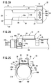
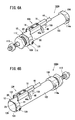
- FIG. 2A is a plan view of the sensor attachment of FIG. 1
- FIG. 2B is an enlarged side view showing the vicinity of the sensor attachment of the fluid pressure cylinder of FIG. 1
- FIG. 2C is an arm of the sensor attachment of FIG.
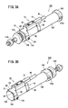
- FIG. 3A is a perspective view of a state in which the position sensor is mounted on the rod cover side using the sensor mounting tool of FIG. 1
- FIG. 3B is a perspective view of the position sensor mounted on the head cover side using the sensor mounting tool of FIG. It is a perspective view of the state.
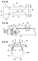
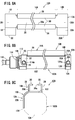
- FIG. 5A is a plan view of the sensor fitting of FIG. 4
- FIG. 5B is an enlarged side view showing the vicinity of the sensor fitting of the fluid pressure cylinder of FIG. 4
- FIG. 5C is an arm of the sensor fitting of FIG.
- FIG. 6A is a perspective view of a state in which the position sensor is mounted on the rod cover side using the sensor mounting tool of FIG. 4
- FIG. 6B is a perspective view of the position sensor mounted on the head cover side using the sensor mounting tool of FIG. It is a perspective view of the state.
- FIG. 8A is a plan view of the sensor fitting of FIG. 7
- FIG. 8B is an enlarged side view showing the vicinity of the sensor fitting of the fluid pressure cylinder of FIG. 7
- FIG. 8C is an arm of the sensor fitting of FIG. It is a schematic diagram which shows the contact part between a part and a cylinder cover.
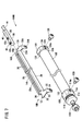
- FIG. 5 is a perspective view showing an example in which two position sensors are mounted on a fluid pressure cylinder using the sensor attachment of FIG. 7.
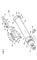
- the fluid pressure cylinder 100 includes a cylinder tube 102, a cylinder cover provided at both ends of the cylinder tube 102, a sensor attachment 10 mounted on the outer peripheral portion of the cylinder tube 102, and a position sensor 18. ..
- the cylinder covers are the head cover 104 and the rod cover 106.
- the cylinder tube 102 of the fluid pressure cylinder 100 is formed in a cylindrical shape by a non-magnetic material, and a piston (not shown) that slides in the axial direction is built in the cylinder tube 102.
- the piston divides the space inside the cylinder tube 102 into a space on the head cover 104 side and a space on the rod cover 106 side, and operates based on the pressure difference between the two spaces.
- a magnet is provided on the outer peripheral portion of the piston so that the position of the piston can be detected by a magnetic field.
- the head cover 104 covers one end of the cylinder tube 102.
- the head cover 104 has four flat surfaces 122, 124, 126, and 128 in the circumferential direction, is formed in a substantially square shape when viewed from one end side in the axial direction, and its corners are chamfered in an arc shape.
- the flat surface 126 of the head cover 104 is formed with a port (not shown) that communicates with the inside of the cylinder tube 102 to supply and discharge air.
- screw holes 114a for screwing the sensor attachment 10 are formed on the flat surface 124 and the flat surface 128 of the head cover 104, respectively.
- the head cover 104 is joined to the cylinder tube 102 by crimping or screwing.
- the rod cover 106 is joined to the other end of the cylinder tube 102.
- the rod cover 106 has four flat surfaces 112, 114, 116, 118 in the circumferential direction, is formed in a substantially square shape when viewed from the other end side in the axial direction, and its corners are chamfered in an arc shape.
- the flat surface 116 of the rod cover 106 is formed with a port (not shown) that communicates with the inside of the cylinder tube 102 to supply and discharge air.
- screw holes 114a for screwing the sensor attachment 10 are formed on the flat surface 114 and the flat surface 118 of the rod cover 106, respectively.
- a fixing screw 120 is screwed into the screw hole 114a.
- the piston rod 110 penetrates the center of the rod cover 106 in the axial direction.
- the piston rod 110 is joined to the piston inside the cylinder tube 102 and moves in the axial direction.
- the sensor attachment 10 is a member for attaching the position sensor 18 to a predetermined position on the outer circumference of the cylinder tube 102, and is attached to the head cover 104 or the rod cover 106 with one screw.
- the sensor attachment 10 includes an arm portion 12, a holder 14, and a capturing portion 16.
- the arm portion 12 is a member formed by bending a plate-shaped member into an L shape, and has a base portion 20 and an extending portion 22 that come into contact with a flat surface on the outer periphery of the head cover 104 or the rod cover 106 (cylinder cover).
- the base portion 20 is formed so as to extend from one end of the holder 14 in the extending direction of the holder 14.
- the bent portion 23 extends from the side portion of the base portion 20, and the bent portion 22 extends from the tip of the bent portion 23 in the direction perpendicular to the base portion 20, that is, in the circumferential direction of the cylinder cover. Has been done.
- the extending portion 22 is formed only on one side of the base portion 20.
- the bent portion 23 is formed in an arc shape equal to the curvature of the chamfered portion of the head cover 104 or the rod cover 106.
- the base portion 20 and the extending portion 22 come into surface contact with the two flat surfaces of the head cover 104 or the rod cover 106 at the same time, and are positioned in the circumferential direction of the holder 14.
- a hole 24 for screwing the arm portion 12 is formed in the central portion of the extending portion 22.
- the holder 14 has a bottom portion 26, a pair of side walls 28 extending from both side portions of the bottom portion 26, and an engaging portion bent from the upper end portion of each side wall 28 toward the facing side wall 28. It has 30 and. As shown in FIG. 1, the bottom portion 26, the side wall 28, and the engaging portion 30 are formed by bending a plate body integrally formed with the arm portion 12.
- the bottom portion 26 is integrally connected to the base portion 20 and extends in the axial direction, and is formed as the same plane as the base portion 20.
- the side wall 28 is formed so as to be perpendicular to the bottom portion 26 and bent in the direction opposite to the extending portion 22.
- a pair of side walls 28 are provided on both sides of the bottom portion 26.
- the engaging portion 30 bends and extends from the upper end of each side wall 28 toward the opposite side wall 28.
- one engaging portion 30 and the other engaging portion 30 are separated from each other with a slit gap 30a through which the protrusion 40 of the position sensor 18 described later is inserted.
- the bottom portion 26, the pair of side walls 28, and the engaging portion 30 form a rail structure that holds the position sensor 18 so as to be slidable in the axial direction.
- the catching portion 16 includes a support portion 17 extending in the longitudinal direction of the holder 14 from the other end of the holder 14, and a clip 35 joined to the support portion 17.
- the support portion 17 is a plate-shaped member integrally extending from the bottom portion 26 of the holder 14.
- the clip 35 is made of, for example, a spring material made of a thin metal plate.
- the clip 35 includes a joint portion 34a joined to the upper surface of the support portion 17, and a pair of leaf spring portions 34b formed in an arc shape having a radius of curvature smaller than that of the cylinder tube 102. ..
- the joint portion 34a is joined to the upper surface of the support portion 17 at a plurality of welded portions 32a.
- a pair of connecting portions 34c bend and extend from both side portions of the joint portion 34a, and leaf spring portions 34b are integrally formed on both side portions of the joint portion 34a via the connecting portion 34c. It is connected.
- the pair of leaf spring portions 34b are curved in an arc shape along the outer diameter of the cylinder tube 102, and have a portion whose tip end side is narrowed in the width direction, and when attached to the cylinder tube 102, the cylinder tube It is configured so that it can be fitted to 102.
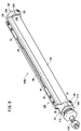
- the position sensor 18 As shown in FIG. 1, as the position sensor 18, a general-purpose product that is generally sold and distributed as a cylinder sensor can be used.
- the position sensor 18 has a columnar rod-shaped portion 38 so that the mounting position can be adjusted in the longitudinal direction of the holder 14.
- the rod-shaped portion 38 has a built-in sensor element that detects magnetism. Further, the rod-shaped portion 38 is formed with a protrusion 40 formed so as to project along the longitudinal direction of the rod-shaped portion 38.
- the rod-shaped portion 38 is formed to have a diameter that can be inserted into the side wall 28 and the engaging portion 30 that form the rail structure.
- the protrusion 40 is formed to have a width slightly smaller than the slit gap 30a, and is mounted on the holder 14 in a state of protruding from the slit gap 30a.
- the position sensor 18 includes a fixing portion 42 for fixing to the holder 14.
- the fixing portion 42 includes a screw hole 42a penetrating from the protrusion 40 to the rod-shaped portion 38, and a screw 42b screwed into the screw hole 42a.
- the fixing portion 42 acts so as to project the tip end portion of the screw 42b from the screw hole 42a and press the rod-shaped portion 38 against the engaging portion 30, thereby fixing the position sensor 18 to the holder 14.
- a wiring 44 that transmits a signal from the sensor element extends from one end of the rod-shaped portion 38 in the longitudinal direction.
- the sensor attachment 10 and the fluid pressure cylinder 100 of the present embodiment are configured as described above, and their operations will be described below.
- the arm portion 12 is brought into contact with the head cover 104 or the rod cover 106, and the catching portion 16 is brought into contact with the cylinder tube 102 to attach the sensor mounting tool 10.
- the sensor attachment 10 is mounted on the rod cover 106 side, as shown in FIG. 2B, the base portion 20 of the arm portion 12 is brought into surface contact with the flat surface 112 of the rod cover 106, and the extending portion 22 of the arm portion 12 is brought into surface contact with the rod cover 106. Is in surface contact with the flat surface 114 of the rod cover 106.
- the rotation of the sensor mounting tool 10 can be prevented, and the sensor mounting tool 10 is positioned in the circumferential direction.
- the catching portion 16 pushes the tip of the leaf spring portion 34b of the clip 35 into the cylinder tube 102 so as to spread the tip thereof, thereby fitting the clip 35 to the cylinder tube 102.
- the clip 35 grips the cylinder tube 102 by the elastic restoring force of the leaf spring portion 34b.
- the fixing screw 120 is tightened into the screw hole 114a through the hole 24 of the extending portion 22 of the arm portion 12, and the mounting work of the sensor attachment 10 is completed. Since the sensor attachment 10 is positioned in the circumferential direction by the arm portion 12 and the clip 35 is fitted to the cylinder tube 102, the sensor attachment 10 is light enough to prevent the hole portion 24 when tightening the fixing screw 120. All you have to do is hold down the tool 10, and you can easily perform the mounting work.
- the arm portion 12 is brought into surface contact with the flat surface of the head cover 104.
- the base portion 20 of the arm portion 12 is brought into contact with the flat surface 122 of the head cover 104
- the extending portion 22 of the arm portion 12 is brought into contact with the flat surface 128 of the head cover 104.
- the clip 35 of the catching portion 16 is fitted into the cylinder tube 102.
- the sensor mounting tool 10 can be mounted on the head cover 104 side by tightening the fixing screw 120 into the screw hole 114a provided on the flat surface 128 of the head cover 104 through the hole 24 of the extending portion 22.
- the sensor attachment 10 and the fluid pressure cylinder 100 of the present embodiment have the following effects.
- the present embodiment relates to a sensor attachment 10 for attaching a position sensor 18 to a fluid pressure cylinder 100 having a cylinder tube 102 and a cylinder cover covering one end and the other end of the cylinder tube 102.
- the sensor fixture 10 includes a holder 14 that holds the position sensor 18 in a rail structure extending in the axial direction of the cylinder tube 102, and an arm portion 12 that extends from one end of the holder 14. Is fixed to the cylinder cover by screwing.
- the arm portion 12 can be directly fixed to the head cover 104 or the rod cover 106 by screwing, so that it is not necessary to provide a band and a band tightening member on the outside of the holder 14 of the sensor attachment 10. Therefore, the protrusion of the sensor attachment 10 to the outside can be suppressed.
- the arm portion 12 may be configured to be fixed to the cylinder cover at a position deviated from the holder 14 in the circumferential direction. As a result, it is possible to prevent interference between the fixing screw 120 used for fixing and the position sensor 18 mounted on the holder 14, and the position sensor 18 can be easily mounted on the holder 14.
- the magnet provided on the piston of the fluid pressure cylinder 100 may be provided at a limited portion in the circumferential direction.
- the cylinder cover has a plurality of flat surfaces 112 and 122 in the circumferential direction, and the arm portion 12 abuts on the flat surfaces 112 and 122 to position the holder 14 in the circumferential direction. It is configured as follows. As a result, the user can mount the sensor attachment 10 on the fluid pressure cylinder 100 without requiring any special learning.
- the arm portion 12 includes a base portion 20 extending in the extending direction of the holder 14 and an extending portion 22 extending from the base portion 20 in the circumferential direction of the cylinder cover. It may be configured so that the extending portion 22 is fixed to the cylinder cover. As a result, the holder 14 can be easily positioned in the circumferential direction, and the fixing screw 120 can be screwed in at a position where the holder 14 does not get in the way.
- the extension portion 22 of the sensor attachment 10 may extend only to one side in the circumferential direction of the holder 14. As a result, the structure can be simplified.
- a clip 35 that fits into the cylinder tube 102 may be provided at the other end of the holder 14.
- the holder 14 can be aligned parallel to the axial direction of the cylinder tube 102. Further, after the clip 35 is fitted, the sensor mounting tool 10 can be prevented from falling off, and the mounting work of the sensor mounting tool 10 becomes easy.
- the fluid pressure cylinder 100 of the present embodiment includes the above-mentioned sensor attachment 10. According to this fluid pressure cylinder 100, since the protrusion to the outside is suppressed, it can be used in a narrow space. Further, in the above-mentioned fluid pressure cylinder 100, the position sensor 18 may be further mounted on the sensor attachment 10.
- the sensor attachment 10A and the fluid pressure cylinder 100A according to the present embodiment are different from the sensor attachment 10 and the fluid pressure cylinder 100 shown in FIG. 1 in the structure of the capturing portion 16A.
- the same components as those of the sensor fitting 10 and the fluid pressure cylinder 100 in FIG. 1 are designated by the same reference numerals, and detailed description thereof will be omitted.
- the sensor attachment 10A has a support portion 48 in which the capture portion 16A is inclined and extends toward the cylinder tube 102.
- the support portions 48 are band-shaped members that extend long in the lateral direction of the holder 14, and are provided in pairs on both side portions of the support portion 17 of the capture portion 16A.
- the pair of support portions 48 are inclined at an angle of contact with two points on the outer circumference of the cylinder tube 102.
- the support portion 48 is integrally formed with the support portion 17, and is formed by being bent at a predetermined angle with respect to the support portion 17 at the bent portion 48a.
- the sensor attachment 10A and the fluid pressure cylinder 100A of the present embodiment are configured as described above, and their actions will be described below.
- the mounting work of the sensor mounting tool 10A is performed by bringing the arm portion 12 into contact with the rod cover 106 and the capturing portion 16A in contact with the cylinder tube 102 as shown in FIG. 6A.
- the holder 14 is positioned in the circumferential direction when the base portion 20 and the extending portion 22 of the arm portion 12 come into contact with the flat surface 112 and the flat surface 114 of the rod cover 106, respectively.
- the support portion 48 of the capture portion 16A comes into contact with two locations on the outer peripheral portion of the cylinder tube 102, whereby the other end portion of the holder 14 is positioned.
- the fixing screw 120 is tightened into the screw hole 114a through the hole 24 of the extending portion 22 of the arm portion 12, and the mounting work of the sensor mounting tool 10A is completed.
- the arm portion 12 may be brought into contact with the flat surface of the head cover 104 and screwed as shown in FIG. 6B.
- the sensor attachment 10A and the fluid pressure cylinder 100A of the present embodiment have the following effects.
- the sensor attachment 10A of the present embodiment is provided at the other end of the holder 14 and includes a support portion 48 that comes into contact with at least two locations on the outer circumference of the cylinder tube 102.
- the holder 14 can be aligned parallel to the axial direction of the cylinder tube 102, and the mounting work of the sensor mounting tool 10A can be facilitated.
- the sensor attachment 10A of the present embodiment is excellent in productivity because it does not need to be welded to another member such as a spring material and can be formed only by bending an integrally formed plate member.
- the sensor attachment 10B and the fluid pressure cylinder 100B include a long holder 14A formed to have the same length as the cylinder tube 102.
- an arm portion 12 is provided at one end of the holder 14A, and a second arm portion 12A is provided as a catching portion 16B at the other end.
- the configuration of the arm portion 12 is the same as that of the arm portion 12 of the sensor attachment 10 of FIG.
- the holder 14A is the same as the holder 14 of the sensor attachment 10 of FIG. 1 except that the holder 14A is long.
- the second arm portion 12A includes a base portion 20A extending from the bottom portion 26 of the holder 14A to the other end side in the longitudinal direction, and an extending portion 22A extending from the base portion 20A via the bending portion 23A. As shown in FIG. 8C, the extending portion 22A extends in a direction substantially perpendicular to the base portion 20A. As shown in FIG. 8B, a hole 24A for screwing is formed in the central portion of the extending portion 22A.
- one arm portion 12 abuts on one cylinder cover (rod cover 106 in the illustrated example), and the other second arm portion 12A is the other cylinder cover. (Head cover 104 in the illustrated example).
- the arm portion 12 and the second arm portion 12A are fixed by fixing screws 120 at one location each. In order to facilitate the fixing work, it is preferable that one arm portion 12 and the other second arm portion 12A are formed on the same side portion of the holder 14A.
- the sensor attachment 10B and the fluid pressure cylinder 100B of the present embodiment have the following effects.
- the sensor attachment 10B of the present embodiment includes a holder 14A having a length equivalent to the length of the cylinder tube 102. At the other end of the holder 14A, a second arm portion 12A screwed to the head cover 104 of the cylinder tube 102 is provided.
- the position sensor 18 can be attached to an arbitrary position of the cylinder tube 102. Further, since one end and the other end of the holder 14A are securely fixed by the arm portion 12 and the second arm portion 12A by screwing, the holder 14A is securely fixed to the long cylinder tube 102 without rattling. be able to.
- the arm portion 12 at one end of the holder 14A and the second arm portion 12A at the other end may be configured to be screwed to the cylinder cover on the same side. ..
- the sensor mounting tool 10B can be mounted by screwing from one side, so that the sensor mounting tool 10B can be easily mounted even when the access direction is limited.
Landscapes
- Engineering & Computer Science (AREA)
- Physics & Mathematics (AREA)
- Fluid Mechanics (AREA)
- Mechanical Engineering (AREA)
- General Engineering & Computer Science (AREA)
- General Physics & Mathematics (AREA)
- Actuator (AREA)
- Measuring Fluid Pressure (AREA)
Priority Applications (4)
| Application Number | Priority Date | Filing Date | Title |
|---|---|---|---|
| EP20835260.9A EP3995702A4 (en) | 2019-07-04 | 2020-06-08 | SENSOR AND HYDRAULIC CYLINDER FIXING TOOL |
| CN202080049054.0A CN114096755B (zh) | 2019-07-04 | 2020-06-08 | 传感器安装件及流体压力缸 |
| US17/624,127 US11835070B2 (en) | 2019-07-04 | 2020-06-08 | Sensor attachment tool and fluid pressure cylinder |
| KR1020227000358A KR102832513B1 (ko) | 2019-07-04 | 2020-06-08 | 센서 부착도구 및 유체압 실린더 |
Applications Claiming Priority (2)
| Application Number | Priority Date | Filing Date | Title |
|---|---|---|---|
| JP2019-125140 | 2019-07-04 | ||
| JP2019125140A JP7063435B2 (ja) | 2019-07-04 | 2019-07-04 | センサ取付具及び流体圧シリンダ |
Publications (1)
| Publication Number | Publication Date |
|---|---|
| WO2021002152A1 true WO2021002152A1 (ja) | 2021-01-07 |
Family
ID=74100554
Family Applications (1)
| Application Number | Title | Priority Date | Filing Date |
|---|---|---|---|
| PCT/JP2020/022552 Ceased WO2021002152A1 (ja) | 2019-07-04 | 2020-06-08 | センサ取付具及び流体圧シリンダ |
Country Status (7)
| Country | Link |
|---|---|
| US (1) | US11835070B2 (enExample) |
| EP (1) | EP3995702A4 (enExample) |
| JP (1) | JP7063435B2 (enExample) |
| KR (1) | KR102832513B1 (enExample) |
| CN (1) | CN114096755B (enExample) |
| TW (1) | TWI747346B (enExample) |
| WO (1) | WO2021002152A1 (enExample) |
Cited By (1)
| Publication number | Priority date | Publication date | Assignee | Title |
|---|---|---|---|---|
| CN114323100A (zh) * | 2021-12-28 | 2022-04-12 | 江苏驭芯传感器科技有限公司 | 一种传感器锁紧装置 |
Families Citing this family (2)
| Publication number | Priority date | Publication date | Assignee | Title |
|---|---|---|---|---|
| JP7320832B2 (ja) * | 2019-08-08 | 2023-08-04 | 株式会社日本アレフ | 固定構造 |
| EP4629491A1 (en) * | 2024-04-03 | 2025-10-08 | Goodrich Actuation Systems SAS | Control system |
Citations (5)
| Publication number | Priority date | Publication date | Assignee | Title |
|---|---|---|---|---|
| JPS6132804U (ja) * | 1984-07-31 | 1986-02-27 | 太陽鉄工株式会社 | 位置検出器付き流体圧シリンダ |
| JPH0386603U (enExample) * | 1989-12-20 | 1991-09-02 | ||
| KR200315514Y1 (ko) * | 2003-02-21 | 2003-06-09 | 케이시시정공 주식회사 | 유ㆍ공압 구동장치용 위치검출기의 고정브라켓 |
| JP2005249128A (ja) | 2004-03-05 | 2005-09-15 | Smc Corp | シリンダの位置検出スイッチ取付具 |
| JP2006266385A (ja) * | 2005-03-23 | 2006-10-05 | Ckd Corp | 流体圧シリンダのセンサ取付具 |
Family Cites Families (31)
| Publication number | Priority date | Publication date | Assignee | Title |
|---|---|---|---|---|
| US2857986A (en) * | 1955-09-19 | 1958-10-28 | Westinghouse Electric Corp | Electrical stopping of motive devices |
| US4176586A (en) * | 1975-01-31 | 1979-12-04 | Manfred Rudle | Piston and cylinder device |
| JPS6128087Y2 (enExample) | 1980-08-22 | 1986-08-21 | ||
| JPS59119486A (ja) * | 1982-12-27 | 1984-07-10 | Fujitsu Ltd | 認識装置 |
| DE3464084D1 (en) * | 1983-04-06 | 1987-07-09 | Bosch Gmbh Robert | Working cylinder |
| US4594487A (en) * | 1984-12-07 | 1986-06-10 | Galland Henning Nopak, Inc. | Mounting means for proximity sensing device |
| DE3609605A1 (de) * | 1986-03-21 | 1987-09-24 | Festo Kg | Linearmotor |
| JPH01129938A (ja) * | 1987-11-16 | 1989-05-23 | Mitsubishi Heavy Ind Ltd | 複合材料及びその製造方法 |
| US4903933A (en) * | 1988-07-27 | 1990-02-27 | Yuda Lawrence F | Clamping apparatus for adjustably positioning switches |
| JPH0368603U (enExample) * | 1989-11-07 | 1991-07-05 | ||
| JP2524604Y2 (ja) | 1991-05-13 | 1997-02-05 | 株式会社コガネイ | 位置検出装置用取付装置 |
| JP3210063B2 (ja) * | 1992-03-23 | 2001-09-17 | 株式会社東芝 | 電力用抵抗体 |
| US5293015A (en) * | 1992-09-28 | 1994-03-08 | Yuda Lawrence F | Apparatus for adjustably positioning switches |
| JP3150078B2 (ja) * | 1997-05-30 | 2001-03-26 | エスエムシー株式会社 | 溝カバー付き流体圧シリンダ |
| DE29717492U1 (de) * | 1997-09-30 | 1997-11-27 | Festo AG & Co, 73734 Esslingen | Befestigungsvorrichtung zur Befestigung eines Sensors |
| JP4547650B2 (ja) * | 2000-09-08 | 2010-09-22 | Smc株式会社 | リニアアクチュエータ |
| JP4496423B2 (ja) * | 2001-01-26 | 2010-07-07 | Smc株式会社 | 位置検出センサの取付構造 |
| JP2003222104A (ja) * | 2002-01-31 | 2003-08-08 | Smc Corp | リニアアクチュエータ |
| JP4099779B2 (ja) * | 2004-08-09 | 2008-06-11 | Smc株式会社 | 流体圧シリンダにおけるセンサ取付機構 |
| DE102004040713A1 (de) * | 2004-08-23 | 2006-03-16 | Numatics Gmbh | Gehäuse mit Längsnut zur Sensoraufnahme |
| JP4582486B2 (ja) * | 2007-11-09 | 2010-11-17 | Smc株式会社 | 流体圧機器におけるスイッチ取付機構 |
| JP4529093B2 (ja) * | 2007-12-19 | 2010-08-25 | Smc株式会社 | 流体圧シリンダのピストン位置検出装置 |
| JP5382591B2 (ja) * | 2010-12-21 | 2014-01-08 | Smc株式会社 | 流体圧シリンダの位置検出装置 |
| JP6098896B2 (ja) * | 2014-06-05 | 2017-03-22 | Smc株式会社 | 流体圧シリンダ用センサ取付装置 |
| CN104632787B (zh) * | 2015-02-12 | 2016-11-30 | 中航飞机起落架有限责任公司 | 一种作动筒内置机械锁锁定状态的自检测机构 |
| JP6314899B2 (ja) * | 2015-04-16 | 2018-04-25 | Smc株式会社 | センサ取付具 |
| BR112017021852A2 (pt) | 2015-04-16 | 2018-07-10 | Smc Corporation | ferramenta de anexação de sensor. |
| CN108138814B (zh) * | 2015-10-08 | 2019-12-17 | Smc株式会社 | 传感器安装工具 |
| CN206386328U (zh) * | 2016-12-12 | 2017-08-08 | Smc株式会社 | 流体压力缸用端盖和流体压力缸 |
| JP6808182B2 (ja) * | 2017-09-07 | 2021-01-06 | Smc株式会社 | 流体圧シリンダ |
| CN208236811U (zh) * | 2018-04-12 | 2018-12-14 | 上海朝田实业股份有限公司 | 一种设有位移传感器的伺服油缸 |
-
2019
- 2019-07-04 JP JP2019125140A patent/JP7063435B2/ja active Active
-
2020
- 2020-06-08 KR KR1020227000358A patent/KR102832513B1/ko active Active
- 2020-06-08 EP EP20835260.9A patent/EP3995702A4/en active Pending
- 2020-06-08 US US17/624,127 patent/US11835070B2/en active Active
- 2020-06-08 WO PCT/JP2020/022552 patent/WO2021002152A1/ja not_active Ceased
- 2020-06-08 CN CN202080049054.0A patent/CN114096755B/zh active Active
- 2020-06-30 TW TW109122055A patent/TWI747346B/zh active
Patent Citations (5)
| Publication number | Priority date | Publication date | Assignee | Title |
|---|---|---|---|---|
| JPS6132804U (ja) * | 1984-07-31 | 1986-02-27 | 太陽鉄工株式会社 | 位置検出器付き流体圧シリンダ |
| JPH0386603U (enExample) * | 1989-12-20 | 1991-09-02 | ||
| KR200315514Y1 (ko) * | 2003-02-21 | 2003-06-09 | 케이시시정공 주식회사 | 유ㆍ공압 구동장치용 위치검출기의 고정브라켓 |
| JP2005249128A (ja) | 2004-03-05 | 2005-09-15 | Smc Corp | シリンダの位置検出スイッチ取付具 |
| JP2006266385A (ja) * | 2005-03-23 | 2006-10-05 | Ckd Corp | 流体圧シリンダのセンサ取付具 |
Non-Patent Citations (1)
| Title |
|---|
| See also references of EP3995702A4 |
Cited By (1)
| Publication number | Priority date | Publication date | Assignee | Title |
|---|---|---|---|---|
| CN114323100A (zh) * | 2021-12-28 | 2022-04-12 | 江苏驭芯传感器科技有限公司 | 一种传感器锁紧装置 |
Also Published As
| Publication number | Publication date |
|---|---|
| EP3995702A1 (en) | 2022-05-11 |
| JP2021011893A (ja) | 2021-02-04 |
| JP7063435B2 (ja) | 2022-05-09 |
| KR102832513B1 (ko) | 2025-07-11 |
| TWI747346B (zh) | 2021-11-21 |
| US20220364580A1 (en) | 2022-11-17 |
| TW202111222A (zh) | 2021-03-16 |
| EP3995702A4 (en) | 2023-07-19 |
| KR20220018560A (ko) | 2022-02-15 |
| US11835070B2 (en) | 2023-12-05 |
| CN114096755B (zh) | 2024-09-13 |
| CN114096755A (zh) | 2022-02-25 |
Similar Documents
| Publication | Publication Date | Title |
|---|---|---|
| JP7063435B2 (ja) | センサ取付具及び流体圧シリンダ | |
| KR100270502B1 (ko) | 유체압실린더에 있어서의 센서부착장치 | |
| US7250753B2 (en) | Sensor attachment mechanism for fluid pressure cylinder | |
| US6892594B2 (en) | Mounting device for sensors | |
| JP6492301B2 (ja) | センサ取付具 | |
| CN111656020A (zh) | 流体压力缸 | |
| JP6314899B2 (ja) | センサ取付具 | |
| JP2008258363A (ja) | 係止装置 | |
| US20180257252A1 (en) | Punch device for marking drilled holes | |
| KR20140063746A (ko) | 위치 센서용 부착 밴드 | |
| JP6422316B2 (ja) | 接触式測長器の保持装置 | |
| JP7209549B2 (ja) | 照明装置の固定器具 | |
| JP5471247B2 (ja) | センサ固定具 | |
| JP2015185185A5 (enExample) | ||
| JP7161933B2 (ja) | マイクロホンアレイ | |
| JP4615407B2 (ja) | 鏡筒保持用治具 | |
| JP2000079573A (ja) | ねじ挟着具 | |
| JP4719063B2 (ja) | 取付具及び取付具の調整方法 | |
| JP3044550U (ja) | 略円柱体の固定具 | |
| JP2000046013A (ja) | 機器における付属物の取り付け装置 | |
| WO2017021782A1 (en) | Sensor housing with integrated continuous rotation of a cover member on a base portion | |
| JP2017101724A (ja) | 位置検出センサ | |
| JPH0612999A (ja) | 電気部品取り付け装置 | |
| JP2001177943A (ja) | コルゲート管保持クリップの取付け治具 | |
| JP2008091171A (ja) | 多光軸光電センサの取付具及び多光軸光電センサの取付構造 |
Legal Events
| Date | Code | Title | Description |
|---|---|---|---|
| 121 | Ep: the epo has been informed by wipo that ep was designated in this application |
Ref document number: 20835260 Country of ref document: EP Kind code of ref document: A1 |
|
| ENP | Entry into the national phase |
Ref document number: 20227000358 Country of ref document: KR Kind code of ref document: A |
|
| NENP | Non-entry into the national phase |
Ref country code: DE |
|
| ENP | Entry into the national phase |
Ref document number: 2020835260 Country of ref document: EP Effective date: 20220204 |