WO2020256473A1 - 이종원소가 도핑된 표면부를 갖는 양극활물질, 및 그 제조 방법 - Google Patents
이종원소가 도핑된 표면부를 갖는 양극활물질, 및 그 제조 방법 Download PDFInfo
- Publication number
- WO2020256473A1 WO2020256473A1 PCT/KR2020/007976 KR2020007976W WO2020256473A1 WO 2020256473 A1 WO2020256473 A1 WO 2020256473A1 KR 2020007976 W KR2020007976 W KR 2020007976W WO 2020256473 A1 WO2020256473 A1 WO 2020256473A1
- Authority
- WO
- WIPO (PCT)
- Prior art keywords
- active material
- positive electrode
- electrode active
- concentration
- lithium
- Prior art date
- Legal status (The legal status is an assumption and is not a legal conclusion. Google has not performed a legal analysis and makes no representation as to the accuracy of the status listed.)
- Ceased
Links
Images






Classifications
-
- H—ELECTRICITY
- H01—ELECTRIC ELEMENTS
- H01M—PROCESSES OR MEANS, e.g. BATTERIES, FOR THE DIRECT CONVERSION OF CHEMICAL ENERGY INTO ELECTRICAL ENERGY
- H01M4/00—Electrodes
- H01M4/02—Electrodes composed of, or comprising, active material
- H01M4/36—Selection of substances as active materials, active masses, active liquids
- H01M4/48—Selection of substances as active materials, active masses, active liquids of inorganic oxides or hydroxides
- H01M4/52—Selection of substances as active materials, active masses, active liquids of inorganic oxides or hydroxides of nickel, cobalt or iron
- H01M4/525—Selection of substances as active materials, active masses, active liquids of inorganic oxides or hydroxides of nickel, cobalt or iron of mixed oxides or hydroxides containing iron, cobalt or nickel for inserting or intercalating light metals, e.g. LiNiO2, LiCoO2 or LiCoOxFy
-
- C—CHEMISTRY; METALLURGY
- C01—INORGANIC CHEMISTRY
- C01G—COMPOUNDS CONTAINING METALS NOT COVERED BY SUBCLASSES C01D OR C01F
- C01G53/00—Compounds of nickel
- C01G53/40—Complex oxides containing nickel and at least one other metal element
- C01G53/42—Complex oxides containing nickel and at least one other metal element containing alkali metals, e.g. LiNiO2
-
- C—CHEMISTRY; METALLURGY
- C01—INORGANIC CHEMISTRY
- C01G—COMPOUNDS CONTAINING METALS NOT COVERED BY SUBCLASSES C01D OR C01F
- C01G53/00—Compounds of nickel
-
- C—CHEMISTRY; METALLURGY
- C01—INORGANIC CHEMISTRY
- C01G—COMPOUNDS CONTAINING METALS NOT COVERED BY SUBCLASSES C01D OR C01F
- C01G53/00—Compounds of nickel
- C01G53/40—Complex oxides containing nickel and at least one other metal element
-
- C—CHEMISTRY; METALLURGY
- C01—INORGANIC CHEMISTRY
- C01G—COMPOUNDS CONTAINING METALS NOT COVERED BY SUBCLASSES C01D OR C01F
- C01G53/00—Compounds of nickel
- C01G53/40—Complex oxides containing nickel and at least one other metal element
- C01G53/42—Complex oxides containing nickel and at least one other metal element containing alkali metals, e.g. LiNiO2
- C01G53/44—Complex oxides containing nickel and at least one other metal element containing alkali metals, e.g. LiNiO2 containing manganese
- C01G53/50—Complex oxides containing nickel and at least one other metal element containing alkali metals, e.g. LiNiO2 containing manganese of the type (MnO2)n-, e.g. Li(NixMn1-x)O2 or Li(MyNixMn1-x-y)O2
-
- C—CHEMISTRY; METALLURGY
- C01—INORGANIC CHEMISTRY
- C01G—COMPOUNDS CONTAINING METALS NOT COVERED BY SUBCLASSES C01D OR C01F
- C01G53/00—Compounds of nickel
- C01G53/80—Compounds containing nickel, with or without oxygen or hydrogen, and containing one or more other elements
- C01G53/82—Compounds containing nickel, with or without oxygen or hydrogen, and containing two or more other elements
-
- H—ELECTRICITY
- H01—ELECTRIC ELEMENTS
- H01M—PROCESSES OR MEANS, e.g. BATTERIES, FOR THE DIRECT CONVERSION OF CHEMICAL ENERGY INTO ELECTRICAL ENERGY
- H01M10/00—Secondary cells; Manufacture thereof
- H01M10/05—Accumulators with non-aqueous electrolyte
- H01M10/052—Li-accumulators
-
- H—ELECTRICITY
- H01—ELECTRIC ELEMENTS
- H01M—PROCESSES OR MEANS, e.g. BATTERIES, FOR THE DIRECT CONVERSION OF CHEMICAL ENERGY INTO ELECTRICAL ENERGY
- H01M4/00—Electrodes
- H01M4/02—Electrodes composed of, or comprising, active material
- H01M4/13—Electrodes for accumulators with non-aqueous electrolyte, e.g. for lithium-accumulators; Processes of manufacture thereof
- H01M4/131—Electrodes based on mixed oxides or hydroxides, or on mixtures of oxides or hydroxides, e.g. LiCoOx
-
- H—ELECTRICITY
- H01—ELECTRIC ELEMENTS
- H01M—PROCESSES OR MEANS, e.g. BATTERIES, FOR THE DIRECT CONVERSION OF CHEMICAL ENERGY INTO ELECTRICAL ENERGY
- H01M4/00—Electrodes
- H01M4/02—Electrodes composed of, or comprising, active material
- H01M4/36—Selection of substances as active materials, active masses, active liquids
- H01M4/362—Composites
- H01M4/366—Composites as layered products
-
- H—ELECTRICITY
- H01—ELECTRIC ELEMENTS
- H01M—PROCESSES OR MEANS, e.g. BATTERIES, FOR THE DIRECT CONVERSION OF CHEMICAL ENERGY INTO ELECTRICAL ENERGY
- H01M4/00—Electrodes
- H01M4/02—Electrodes composed of, or comprising, active material
- H01M4/36—Selection of substances as active materials, active masses, active liquids
- H01M4/38—Selection of substances as active materials, active masses, active liquids of elements or alloys
- H01M4/381—Alkaline or alkaline earth metals elements
- H01M4/382—Lithium
-
- H—ELECTRICITY
- H01—ELECTRIC ELEMENTS
- H01M—PROCESSES OR MEANS, e.g. BATTERIES, FOR THE DIRECT CONVERSION OF CHEMICAL ENERGY INTO ELECTRICAL ENERGY
- H01M4/00—Electrodes
- H01M4/02—Electrodes composed of, or comprising, active material
- H01M4/36—Selection of substances as active materials, active masses, active liquids
- H01M4/48—Selection of substances as active materials, active masses, active liquids of inorganic oxides or hydroxides
- H01M4/50—Selection of substances as active materials, active masses, active liquids of inorganic oxides or hydroxides of manganese
- H01M4/505—Selection of substances as active materials, active masses, active liquids of inorganic oxides or hydroxides of manganese of mixed oxides or hydroxides containing manganese for inserting or intercalating light metals, e.g. LiMn2O4 or LiMn2OxFy
-
- C—CHEMISTRY; METALLURGY
- C01—INORGANIC CHEMISTRY
- C01P—INDEXING SCHEME RELATING TO STRUCTURAL AND PHYSICAL ASPECTS OF SOLID INORGANIC COMPOUNDS
- C01P2002/00—Crystal-structural characteristics
- C01P2002/50—Solid solutions
- C01P2002/52—Solid solutions containing elements as dopants
-
- C—CHEMISTRY; METALLURGY
- C01—INORGANIC CHEMISTRY
- C01P—INDEXING SCHEME RELATING TO STRUCTURAL AND PHYSICAL ASPECTS OF SOLID INORGANIC COMPOUNDS
- C01P2002/00—Crystal-structural characteristics
- C01P2002/50—Solid solutions
- C01P2002/52—Solid solutions containing elements as dopants
- C01P2002/54—Solid solutions containing elements as dopants one element only
-
- C—CHEMISTRY; METALLURGY
- C01—INORGANIC CHEMISTRY
- C01P—INDEXING SCHEME RELATING TO STRUCTURAL AND PHYSICAL ASPECTS OF SOLID INORGANIC COMPOUNDS
- C01P2002/00—Crystal-structural characteristics
- C01P2002/70—Crystal-structural characteristics defined by measured X-ray, neutron or electron diffraction data
- C01P2002/76—Crystal-structural characteristics defined by measured X-ray, neutron or electron diffraction data by a space-group or by other symmetry indications
-
- C—CHEMISTRY; METALLURGY
- C01—INORGANIC CHEMISTRY
- C01P—INDEXING SCHEME RELATING TO STRUCTURAL AND PHYSICAL ASPECTS OF SOLID INORGANIC COMPOUNDS
- C01P2004/00—Particle morphology
- C01P2004/01—Particle morphology depicted by an image
- C01P2004/03—Particle morphology depicted by an image obtained by SEM
-
- C—CHEMISTRY; METALLURGY
- C01—INORGANIC CHEMISTRY
- C01P—INDEXING SCHEME RELATING TO STRUCTURAL AND PHYSICAL ASPECTS OF SOLID INORGANIC COMPOUNDS
- C01P2004/00—Particle morphology
- C01P2004/01—Particle morphology depicted by an image
- C01P2004/04—Particle morphology depicted by an image obtained by TEM, STEM, STM or AFM
-
- C—CHEMISTRY; METALLURGY
- C01—INORGANIC CHEMISTRY
- C01P—INDEXING SCHEME RELATING TO STRUCTURAL AND PHYSICAL ASPECTS OF SOLID INORGANIC COMPOUNDS
- C01P2004/00—Particle morphology
- C01P2004/10—Particle morphology extending in one dimension, e.g. needle-like
- C01P2004/16—Nanowires or nanorods, i.e. solid nanofibres with two nearly equal dimensions between 1-100 nanometer
-
- C—CHEMISTRY; METALLURGY
- C01—INORGANIC CHEMISTRY
- C01P—INDEXING SCHEME RELATING TO STRUCTURAL AND PHYSICAL ASPECTS OF SOLID INORGANIC COMPOUNDS
- C01P2004/00—Particle morphology
- C01P2004/30—Particle morphology extending in three dimensions
- C01P2004/45—Aggregated particles or particles with an intergrown morphology
-
- C—CHEMISTRY; METALLURGY
- C01—INORGANIC CHEMISTRY
- C01P—INDEXING SCHEME RELATING TO STRUCTURAL AND PHYSICAL ASPECTS OF SOLID INORGANIC COMPOUNDS
- C01P2004/00—Particle morphology
- C01P2004/50—Agglomerated particles
-
- C—CHEMISTRY; METALLURGY
- C01—INORGANIC CHEMISTRY
- C01P—INDEXING SCHEME RELATING TO STRUCTURAL AND PHYSICAL ASPECTS OF SOLID INORGANIC COMPOUNDS
- C01P2004/00—Particle morphology
- C01P2004/51—Particles with a specific particle size distribution
-
- C—CHEMISTRY; METALLURGY
- C01—INORGANIC CHEMISTRY
- C01P—INDEXING SCHEME RELATING TO STRUCTURAL AND PHYSICAL ASPECTS OF SOLID INORGANIC COMPOUNDS
- C01P2004/00—Particle morphology
- C01P2004/60—Particles characterised by their size
- C01P2004/61—Micrometer sized, i.e. from 1-100 micrometer
-
- C—CHEMISTRY; METALLURGY
- C01—INORGANIC CHEMISTRY
- C01P—INDEXING SCHEME RELATING TO STRUCTURAL AND PHYSICAL ASPECTS OF SOLID INORGANIC COMPOUNDS
- C01P2004/00—Particle morphology
- C01P2004/80—Particles consisting of a mixture of two or more inorganic phases
- C01P2004/82—Particles consisting of a mixture of two or more inorganic phases two phases having the same anion, e.g. both oxidic phases
-
- C—CHEMISTRY; METALLURGY
- C01—INORGANIC CHEMISTRY
- C01P—INDEXING SCHEME RELATING TO STRUCTURAL AND PHYSICAL ASPECTS OF SOLID INORGANIC COMPOUNDS
- C01P2004/00—Particle morphology
- C01P2004/80—Particles consisting of a mixture of two or more inorganic phases
- C01P2004/82—Particles consisting of a mixture of two or more inorganic phases two phases having the same anion, e.g. both oxidic phases
- C01P2004/84—Particles consisting of a mixture of two or more inorganic phases two phases having the same anion, e.g. both oxidic phases one phase coated with the other
-
- C—CHEMISTRY; METALLURGY
- C01—INORGANIC CHEMISTRY
- C01P—INDEXING SCHEME RELATING TO STRUCTURAL AND PHYSICAL ASPECTS OF SOLID INORGANIC COMPOUNDS
- C01P2006/00—Physical properties of inorganic compounds
- C01P2006/40—Electric properties
-
- H—ELECTRICITY
- H01—ELECTRIC ELEMENTS
- H01M—PROCESSES OR MEANS, e.g. BATTERIES, FOR THE DIRECT CONVERSION OF CHEMICAL ENERGY INTO ELECTRICAL ENERGY
- H01M4/00—Electrodes
- H01M4/02—Electrodes composed of, or comprising, active material
- H01M2004/026—Electrodes composed of, or comprising, active material characterised by the polarity
- H01M2004/028—Positive electrodes
-
- H—ELECTRICITY
- H01—ELECTRIC ELEMENTS
- H01M—PROCESSES OR MEANS, e.g. BATTERIES, FOR THE DIRECT CONVERSION OF CHEMICAL ENERGY INTO ELECTRICAL ENERGY
- H01M2220/00—Batteries for particular applications
- H01M2220/20—Batteries in motive systems, e.g. vehicle, ship, plane
-
- Y—GENERAL TAGGING OF NEW TECHNOLOGICAL DEVELOPMENTS; GENERAL TAGGING OF CROSS-SECTIONAL TECHNOLOGIES SPANNING OVER SEVERAL SECTIONS OF THE IPC; TECHNICAL SUBJECTS COVERED BY FORMER USPC CROSS-REFERENCE ART COLLECTIONS [XRACs] AND DIGESTS
- Y02—TECHNOLOGIES OR APPLICATIONS FOR MITIGATION OR ADAPTATION AGAINST CLIMATE CHANGE
- Y02E—REDUCTION OF GREENHOUSE GAS [GHG] EMISSIONS, RELATED TO ENERGY GENERATION, TRANSMISSION OR DISTRIBUTION
- Y02E60/00—Enabling technologies; Technologies with a potential or indirect contribution to GHG emissions mitigation
- Y02E60/10—Energy storage using batteries
Definitions
- the present application relates to a positive electrode active material and a method of manufacturing the same, and more particularly, to a positive electrode active material having a surface portion doped with heterogeneous elements, a method of manufacturing the same, and a lithium secondary battery including the same.
- Korean Patent Laid-Open Publication No. 10-2014-0119621 (application number 10-2013-0150315) uses a precursor for manufacturing an excess lithium cathode active material, controls the type and composition of the metal substituted in the precursor, and the type of metal added. And by controlling the amount of addition, a secondary battery having a high voltage capacity and long life characteristics is disclosed.
- One technical problem to be solved by the present application is to provide a high-capacity positive electrode active material including a high content of nickel and having improved capacity characteristics and life characteristics, a manufacturing method thereof, and a lithium secondary battery including the same.
- Another technical problem to be solved by the present application is to prepare a positive electrode active material using a novel method, thereby providing a crystal structure on the surface of the positive electrode active material differently from the inside, thereby including a long-lived positive electrode active material, its manufacturing method, and the same. It is to provide a lithium secondary battery.
- Another technical problem to be solved by the present application is to provide a positive electrode active material having high stability, a method of manufacturing the same, and a lithium secondary battery including the same.
- Another technical problem to be solved by the present application is to provide a positive electrode active material having a high discharge capacity and at the same time minimizing the reduction in lifespan according to the number of charging and discharging, a manufacturing method thereof, and a lithium secondary battery including the same.
- embodiments of the present invention include a positive electrode active material precursor including a first secondary particle consisting of a group of a plurality of first primary particles, the positive electrode active material precursor is a first central portion of the formula (1) and , A positive electrode active material precursor comprising a first surface portion consisting of the following Chemical Formula 2, wherein the first surface portion has a thickness of 2% to 20% with respect to an average radius of the positive electrode active material precursor.
- M1 is cobalt (Co), manganese (Mn), aluminum (Al) or a mixture thereof
- M2 is tungsten (W), molybdenum (Mo), tantalum (Ta), niobium (Nb), hafnium (Hf) , Silicon (Si), tin (Sn), zirconium (Zr), calcium (Ca), germanium (Ge), gallium (Ga), indium (In), ruthenium (Ru), tellurium (Te), antimony ( Sb), iron (Fe), chromium (Cr), vanadium (V) and titanium (Ti), or a mixture thereof, and 0 ⁇ x ⁇ 0.2, 0 ⁇ y ⁇ 0.2, 0.005 ⁇ z ⁇ 0.1.
- the first primary particle includes a length in the a-axis direction different from the length in the c-axis direction, wherein the length of the a-axis direction of the first primary particles provided on the first surface portion May include being provided longer than the length in the a-axis direction of the first primary particles provided in the first center.
- the first central portion and the first surface portion is a rock salt layered structure (R-3m) including a first lithium layer composed of only lithium and a first transition metal layer composed of only a transition metal. Space group).
- R-3m rock salt layered structure
- the present invention is a positive electrode active material prepared by mixing the above-described positive electrode active material precursor with a lithium compound and then firing, wherein the positive electrode active material comprises second secondary particles consisting of a group of a plurality of second primary particles.
- the positive electrode active material includes a second central portion, which is a portion adjacent to the center of the positive electrode active material, and a second surface portion provided on an outer surface of the positive electrode active material so as to surround the second central portion, and the second central portion and the second central portion.
- the surface part contains lithium, nickel, oxygen, M1 and M2, the M1 is cobalt (Co), manganese (Mn), aluminum (Al) or a mixture thereof, and M2 is tungsten (W), molybdenum (Mo ), tantalum (Ta), niobium (Nb), hafnium (Hf), silicon (Si), tin (Sn), zirconium (Zr), calcium (Ca), germanium (Ge), gallium (Ga), indium (In ), ruthenium (Ru), tellurium (Te), antimony (Sb), iron (Fe), chromium (Cr), vanadium (V) and titanium (Ti), or a mixture thereof, and the M2 is 0.5 mol% It includes a positive electrode active material containing from 10 mol% to.
- the M2 may include 0.5 mol% to 2 mol%.
- the concentration of M2 in the second center may be lower than the concentration of M2 in the second surface portion.
- the concentration of M2 in the second surface portion may include having a concentration gradient such that the concentration increases as the concentration increases as the distance from the second center to the outside.
- the positive electrode active material may be represented by Formula 3 below.
- M1 is cobalt (Co), manganese (Mn), aluminum (Al) or a mixture thereof
- M2 is tungsten (W), molybdenum (Mo), tantalum (Ta), niobium (Nb), hafnium (Hf) , Silicon (Si), tin (Sn), zirconium (Zr), calcium (Ca), germanium (Ge), gallium (Ga), indium (In), ruthenium (Ru), tellurium (Te), antimony ( Sb), iron (Fe), chromium (Cr), vanadium (V) and titanium (Ti), or a mixture thereof, and 0.8 ⁇ a ⁇ 1.1, 0 ⁇ b ⁇ 0.2, 0.001 ⁇ c ⁇ 0.05, 0 ⁇ d ⁇ It is 2.
- the thickness of the second surface portion with respect to the average radius of the positive electrode active material may include a length of 2% to 20%.
- the positive electrode active material includes at least a portion of a first lithium layer composed of only lithium, a first transition metal layer composed of only a transition metal, and lithium constituting the first lithium layer.
- a transition metal layer may be included, and the second surface portion may further include an ordering structure in which the second lithium layer and the second transition metal layer are alternately and regularly provided.
- the lattice formed by the second lithium layer and the second transition metal layer is a superlattice whose a-axis is increased by twice the lattice formed by the first lithium layer and the first transition metal layer ( superlattice), and the superlattice may include those having 6 lithium elements and 1 transition metal element.
- the second primary particle includes a length in the a-axis direction different from the length in the c-axis direction, wherein the length in the a-axis direction of the primary particles provided on the second surface portion is the It may include those provided longer than the length in the a-axis direction of the primary particles provided in the second center.
- the second primary particle includes a length in the a-axis direction different from the length in the c-axis direction, wherein the second primary particle increases from the second center toward the second surface portion. It may be provided to increase the aspect ratio of the length in the a-axis direction to the length in the c-axis direction.
- the positive electrode active material includes a concentration holding portion having a constant concentration of the nickel and M1, and a concentration gradient having a concentration gradient of at least one of the nickel and M1, and The concentration may be provided to have a concentration gradient in the concentration maintaining unit and the concentration gradient unit.
- the M2 may be provided in which the average concentration of the M2 in the concentration gradient portion is higher than the average concentration of the M2 in the concentration maintaining portion.
- the concentration maintaining part is included in the second center, the concentration gradient part is included in the second surface part, and the nickel and the M2 in the concentration gradient part move from the inside of the positive electrode active material to the surface.
- the concentration is provided to decrease gradually, the M1 is provided to increase the concentration from the inside to the surface of the positive electrode active material, and the M1 may contain Co (cobalt).
- it includes a positive electrode for a secondary battery comprising the above-described positive electrode active material.
- anode A negative electrode made of graphite or lithium metal; And a lithium secondary battery including an electrolyte.
- the present invention includes a battery module including the above-described lithium secondary battery as a unit cell.
- the battery pack is used as a power source for medium and large devices, and the medium and large devices are selected from the group consisting of electric vehicles, hybrid electric vehicles, plug-in hybrid electric vehicles, and power storage systems. It may include a battery pack.
- the positive electrode active material according to the present invention includes secondary particles formed by agglomeration of a plurality of primary particles, and the secondary particles are provided by doping a heterogeneous element together with a high content of nickel. can do.
- the heterogeneous element may control the shape of the primary particles, the orientation of the single particles, and the like, thereby providing a positive electrode active material that can be stably used for a long time with a high discharge capacity.
- the positive electrode active material according to the present invention improves the cycle characteristics of the positive electrode active material containing a high content of nickel by doping with heterogeneous elements, but at the same time, by doping by a novel method, it uses a lower content of heterogeneous elements than the conventional capacity. The characteristics are prevented from deteriorating and the cycle characteristics are excellently improved at the same time.
- FIG. 1A is a schematic diagram of a cross-section of a positive electrode active material according to an embodiment of the present invention.
- 1B is a diagram schematically showing the movement of lithium ions in a positive electrode active material according to an embodiment of the present invention.
- Example 2A is an SEM photograph of a cathode active material according to Example 1 of the present invention.
- Example 2B is a graph analyzing the elemental composition of the cathode active material precursor according to Example 1 of the present invention.
- 2C are graphs analyzing the elemental composition of the positive electrode active material of Example 1 of the present invention.
- Example 3 is a TEM photograph and a SAED pattern of a surface portion of a positive electrode active material according to Example 1 of the present invention.
- Example 4 is a TEM photograph and a SAED pattern of a central portion of a positive electrode active material according to Example 2 of the present invention.
- Example 5 is a graph measuring the discharge capacity of a lithium secondary battery including the positive electrode active material according to Example 1 and Comparative Example 1 of the present invention.
- Example 6 is a graph measuring the life characteristics of lithium secondary batteries including positive electrode active materials according to Example 1 and Comparative Example 1 of the present invention.
- Example 7 is a graph measuring differential capacity according to the number of charge/discharge times of lithium secondary batteries including positive electrode active materials according to Example 1 and Comparative Example 1 of the present invention.
- Example 8 is a graph for evaluating the thermal stability of lithium secondary batteries including positive electrode active materials according to Example 1 and Comparative Example 1 of the present invention.
- Example 11 is an SEM image showing a cross section of a precursor according to Example 6 of the present invention.
- Example 12 is an SEM image showing a cathode active material, which is a sintered body of Example 6 and Comparative Example 5.
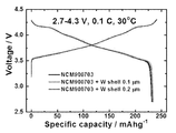
- Example 13 is a graph showing the capacity characteristics of Examples 5 and 6 and Comparative Example 5 of the present invention.
- FIG. 16 is a graph showing cycle characteristics of Examples 2 and 6 and Comparative Examples 2 and 5.
- FIG. 16 is a graph showing cycle characteristics of Examples 2 and 6 and Comparative Examples 2 and 5.
- 17 is a graph showing capacity characteristics of Examples 7 to 9 and Comparative Examples 6 and 7 of the present invention.
- Example 19 is a graph showing the capacity characteristics of Example 10 and Comparative Example 8.
- Example 20 is a graph showing the cycle characteristics of Example 10 and Comparative Example 8.
- Example 21 is a graph showing the capacity characteristics of Example 10 and Comparative Example 9.
- Example 22 is a graph showing the cycle characteristics of Example 10 and Comparative Example 9.
- Example 23 is an SEM image showing a cross section of the precursor of Example 11.
- Example 24 is an SEM image showing a cross section of a cathode active material, which is a fired body of Example 11.
- 25A and 25B are SEM images of the sintered cathode active material of Comparative Example 11 (left) and Example 11 (right).
- 26 is a graph showing the element composition in the positive electrode active material that is a precursor and a sintered body of Comparative Examples 10 and 11.
- Example 27 is a graph showing capacity characteristics of Example 11, Comparative Example 10, and Comparative Example 11.
- variable includes all values within the stated range, including the stated endpoints of the range.
- a range of "5 to 10" includes values of 5, 6, 7, 8, 9, and 10, as well as any subranges such as 6 to 10, 7 to 10, 6 to 9, 7 to 9, etc.
- Inclusive and it will be understood to include any values between integers that are reasonable in the scope of the stated range, such as 5.5, 6.5, 7.5, 5.5 to 8.5 and 6.5 to 9, and the like.
- “10% to 30%” ranges from 10% to 15%, 12% to 18, as well as values such as 10%, 11%, 12%, 13%, and all integers up to 30%. It will be understood to include any subranges such as %, 20% to 30%, and the like, and include any values between reasonable integers within the scope of the stated range, such as 10.5%, 15.5%, 25.5%, and the like.
- the size and particle diameter of various particles are numerically quantified by a measurement method to express the average size of the population.
- a measurement method to express the average size of the population.
- the present invention provides a positive electrode active material precursor including a first secondary particle composed of a group of a plurality of first primary particles, wherein the positive electrode active material precursor has a first central part of the following formula (1), and the following formula:
- a positive electrode active material precursor comprising a first surface portion consisting of two, and having a thickness of the first surface portion with a length of 2% to 20% with respect to an average radius of the positive electrode active material precursor.
- M1 is cobalt (Co), manganese (Mn), aluminum (Al) or a mixture thereof
- M2 is tungsten (W), molybdenum (Mo), tantalum (Ta), niobium (Nb), hafnium (Hf) , Silicon (Si), tin (Sn), zirconium (Zr), calcium (Ca), germanium (Ge), gallium (Ga), indium (In), ruthenium (Ru), tellurium (Te), antimony ( Sb), iron (Fe), chromium (Cr), vanadium (V) and titanium (Ti), or a mixture thereof, and 0 ⁇ x ⁇ 0.2, 0 ⁇ y ⁇ 0.2, 0.005 ⁇ z ⁇ 0.1.
- the first primary particles include those having different lengths in the a-axis direction with respect to the lengths in the c-axis direction, and the length in the a-axis direction of the first primary particles provided on the first surface portion is in the first center It may include those provided longer than the length of the a-axis direction of the provided first primary particles.
- the first secondary particles may have a substantially spherical shape, and the first primary particles have a rod shape having different lengths in the a-axis direction with respect to the length in the c-axis direction. It can be made in the shape of. At least some of the first primary particles may be aligned in a radial direction, and the first primary particles may be oriented such that the a-axis direction is toward the center of the first secondary particle in a direction from the center of the positive electrode active material toward the surface. have.
- the first primary particles may be provided to have a more oriented shape in the surface portion than in the center portion of the first secondary particle, and the length in the a-axis direction may be longer in the surface portion than in the center portion.
- the first primary particles may be provided in a form in which a length in the a-axis direction increases in a direction from the center toward the surface part.
- a first central portion and a first surface portion may be formed in a different compounding manner, and the first central portion and the first surface portion may include a first lithium layer composed of only lithium and It may include those having a rock salt layered structure (R-3m space group) including first transition metal layers made of only transition metals.
- the cathode active material precursor may have a rock salt layered structure having the same crystal structure even though the first central portion and the second surface portion are formed of different compounds.
- the first primary particles provided in the first central portion and the second surface portion are not provided in a different shape, but have continuity in the shape of a rod shape. It can be provided.
- FIG. 1A is a schematic diagram of a cross-section of a positive electrode active material according to an exemplary embodiment of the present invention
- FIG. 1B is a schematic diagram showing movement of lithium ions in a positive electrode active material according to an exemplary embodiment of the present invention.
- the present invention is a positive electrode active material prepared by mixing the above-described positive electrode active material precursor with a lithium compound and then firing, and the positive electrode active material is a first composed of a group of a plurality of second primary particles 10.
- the positive electrode active material may include a second central portion, which is a portion adjacent to the center of the positive electrode active material, and a second surface portion provided on the outer surface of the positive electrode active material so as to surround the second central portion. have.
- the second central portion and the second surface portion contain lithium, nickel, oxygen, M1 and M2, the M1 is cobalt (Co), manganese (Mn), aluminum (Al) or a mixture thereof, and M2 is tungsten (W), molybdenum (Mo), tantalum (Ta), niobium (Nb), hafnium (Hf), silicon (Si), tin (Sn), zirconium (Zr), calcium (Ca), germanium (Ge), gallium (Ga), indium (In), ruthenium (Ru), tellurium (Te), antimony (Sb), iron (Fe), chromium (Cr), vanadium (V) and titanium (Ti), or mixtures thereof ,
- the M2 may include 0.5 mol% to 10 mol%.
- the M2 is about 0.55 mol% to 10 mol%, about 0.6 mol% to 10 mol%, about 0.65 mol% to 10 mol%, about 0.7 mol% to 10 mol%, about 0.75 mol% to 10 mol%, about 0.8 mol % To 10 mol%, about 0.85 mol% to 10 mol%, about 0.9 mol% to 10 mol%, about 0.95 mol% to 10 mol%, or about 0.5 mol% to 9.5 mol%, about 0.5 mol% to 9 mol%, about 0.5 mol% to 8.5 mol%, about 0.5 mol% to 8 mol%, about 0.5 mol% to 7.5 mol%, about 0.5 mol% to 7 mol%, about 0.5 mol% to 6.5 mol%, about 0.5 mol% to 6 mol%, about It may be 0.5 mol% to 5.5 mol%, approximately 0.5 mol% to 5 mol%.
- the M2 may be about 1 mol% to 10 mol%, about 2 mol% to 10 mol%, about 3 mol% to 10 mol%, about 4 mol% to 10 mol%, and about 5 mol% to 10 mol%. More specifically, the M2 may be 0.5 mol% to 2 mol%.
- the concentration of M2 in the second center may be lower than the concentration of M2 in the second surface portion.
- the concentration of M2 in the second surface portion may have a concentration gradient such that the concentration increases as the concentration increases from the second center toward the outside.
- the positive electrode active material may be represented by the following formula (3).
- M1 is cobalt (Co), manganese (Mn), aluminum (Al) or a mixture thereof
- M2 is tungsten (W), molybdenum (Mo), tantalum (Ta), niobium (Nb), hafnium (Hf) , Silicon (Si), tin (Sn), zirconium (Zr), calcium (Ca), germanium (Ge), gallium (Ga), indium (In), ruthenium (Ru), tellurium (Te), antimony ( Sb), iron (Fe), chromium (Cr), vanadium (V) and titanium (Ti), or a mixture thereof, and 0.8 ⁇ a ⁇ 1.1, 0 ⁇ b ⁇ 0.2, 0.001 ⁇ c ⁇ 0.05, 0 ⁇ d ⁇ It is 2.
- b may be 0 ⁇ b ⁇ 0.18, 0 ⁇ b ⁇ 0.15, 0 ⁇ b ⁇ 0.13, 0 ⁇ b ⁇ 0.1, 0 ⁇ b ⁇ 0.07, 0 ⁇ b ⁇ 0.05, or 0 ⁇ b ⁇ 0.03, c is 0.001 ⁇ c ⁇ 0.045, 0.001 ⁇ c ⁇ 0.04, 0.001 ⁇ c ⁇ 0.035, 0.001 ⁇ c ⁇ 0.03, 0.001 ⁇ c ⁇ 0.025, 0.001 ⁇ c ⁇ 0.02, 0.001 ⁇ c ⁇ 0.015, or 0.001 ⁇ c ⁇ 0.012 Can be
- the thickness of the second surface portion relative to the average radius of the positive electrode active material may be 2% to 20% in length. Specifically, the thickness of the second surface portion is about 2.5% to 20%, about 3% to 20%, about 4% to 20%, about 5% to 20%, about 6% to 20%, about 7% to 20%, approximately 8% to 20%, approximately 9% to 20%, approximately 10% to 20%, or approximately 2% to 19%, approximately 2% to 18%, approximately 2% to 17%, approximately 2% To 16%, approximately 2% to 15%, approximately 2% to 14%, approximately 2% to 13%, approximately 2% to 12%, approximately 2% to 11%, approximately 2% to 10%.
- the positive electrode active material at least a part of lithium constituting the first lithium layer, the first transition metal layers composed of only a transition metal, and a first lithium layer composed of only lithium is regularly substituted with a transition metal.
- the second lithium layer and a second transition metal layer in which at least a portion of the first transition metal layer is regularly substituted with lithium, and the second central portion and the second surface portion include a first lithium layer and a first transition metal layer.
- the second surface portion may further include an ordering structure (cation ordering) in which the second lithium layer and the second transition metal layer are alternately and regularly provided.
- the lattice formed by the second lithium layer and the second transition metal layer includes a superlattice in which an a-axis is increased by twice the lattice formed by the first lithium layer and the first transition metal layer,
- the superlattice may include those having 6 lithium elements and 1 transition metal element.
- the first central portion and the first surface portion are formed of only the first lithium layer and the first transition metal layer.
- the first central portion and the first surface portion are formed of different chemical formulas.
- the first surface portion is doped with a heterogeneous element.
- a chemical formula between the second central portion and the second surface portion may be substantially similar, and specifically, a compound constituting the positive electrode active material as a whole May be provided as a bulk having a concentration gradient in at least a portion, a constant concentration in at least a portion, or a concentration gradient as a whole, or in a state in which the concentration is not entirely controlled.
- the heterogeneous element present only in the second surface portion may be diffused to the second central portion, and the heterogeneous element may be provided to have a concentration gradient from at least a portion of the second central portion through the second surface portion.
- heteroelements doped only on the first surface portion of the positive electrode active material precursor may be provided on both sides of the second central portion and the second surface portion of the positive electrode active material.
- the heterogeneous element provided on the second surface portion may be provided to increase in concentration in a direction from the center of the second secondary particle toward the outermost surface.
- the second primary particles 10 include those having different lengths in the a-axis direction with respect to the lengths in the c-axis direction, and the second primary particles 10 provided on the second surface portion
- the length in the a-axis direction of may be longer than the length in the a-axis direction of the second primary particles 10 provided in the second center portion.
- the second primary particles 10 are provided in a rod-shaped shape, but compared to the second primary particles 10 provided in the second center, the second primary particles 10 provided on the second surface portion are more It may be provided in a rod-shaped shape with an increased aspect ratio, and the orientation of the second primary particles 10 provided on the second surface portion (in a direction from the surface of the second secondary particles toward the center, the second primary particles 10 ) Is oriented in the a-axis direction), so that lithium ions can easily move from the outer surface to the inner surface of the second secondary particle 100.
- the second primary particles 10 include those having different lengths in the a-axis direction with respect to the lengths in the c-axis direction, and the second primary particles 10 move from the second center to the second surface. It may be provided to increase the aspect ratio of the length in the a-axis direction to the length in the c-axis direction.
- the positive electrode active material includes a concentration holding unit having a constant concentration of nickel and M1, a concentration gradient having a concentration gradient of at least one of the nickel and M1, and the concentration of M2 is the concentration holding unit And may be provided to have a concentration gradient in the concentration gradient portion.
- the average concentration of M2 in the concentration gradient part may be higher than the average concentration of M2 in the concentration maintaining part.
- the concentration maintaining part is included in the second center, the concentration gradient part is included in the second surface part, and the nickel and M2 in the concentration gradient part decrease in concentration from the inside of the positive electrode active material to the surface. Is provided, and the concentration of M1 increases from the inside to the surface of the positive electrode active material, and the M1 may include Co (cobalt).
- the present invention includes a positive electrode for a secondary battery including the positive electrode active material described above.
- the present invention is the above-described anode; A negative electrode made of graphite or lithium metal; And a lithium secondary battery including an electrolyte.
- the present invention includes a battery module including the aforementioned lithium secondary battery as a unit cell.
- the battery pack is used as a power source for medium and large devices, and the medium and large devices are selected from the group consisting of electric vehicles, hybrid electric vehicles, plug-in hybrid electric vehicles, and power storage systems. It includes a battery pack.
- embodiments of the present invention include: preparing a first metal solution containing nickel, a second metal solution containing M1, and a third metal solution containing M2; Adding the first metal solution and the second metal solution to a co-precipitation reactor to first co-precipitate to prepare a pre-precursor; Preparing a positive electrode active material precursor having a first surface portion formed on the outer surface of the pre-precursor by adding the first metal solution and the second metal solution to the co-precipitation reactor and simultaneously adding the third metal solution; And mixing the cathode active material precursor with a lithium compound and then firing to prepare a cathode active material.
- the preliminary precursor includes a first central portion represented by Formula 1 below, and the cathode active material precursor is provided to surround the first central portion, and includes a first surface portion represented by Formula 2 below, and the cathode active material is Represented by Formula 3, the thickness of the first surface portion with respect to the average radius of the positive electrode active material precursor is provided in a length of 2% to 20%.
- M1 is cobalt (Co), manganese (Mn), aluminum (Al), or a mixture thereof
- M2 is tungsten (W), molybdenum (Mo), magnesium (Mg), calcium (Ca), titanium (Ti) , Vanadium (V), chromium (Cr), iron (Fe), copper (Cu), zinc (Zn), gallium (Ga), strontium (Sr), yttrium (Y), zirconium (Zr), niobium (Nb) , Ruthenium (Ru), fluorine (F), barium (Ba), or a mixture thereof, and 0 ⁇ x ⁇ 0.2, 0 ⁇ y ⁇ 0.2, 0.005 ⁇ z ⁇ 0.1, 0.8 ⁇ a ⁇ 1.1, 0 ⁇ b ⁇ 0.2 , 0.001 ⁇ c ⁇ 0.05, and 0 ⁇ d ⁇ 2.
- NiSO 4 6H 2 O, Samjeon Chemical manganese sulfate aqueous solution
- MnSO 4 H 2 O, Samjeon Chemical manganese sulfate aqueous solution
- CoSO 4 7H 2 O, Samjeon Chemical cobalt sulfate aqueous solution
- N 2 gas was supplied to the reactor at a rate of 6 liters/minute, and the reactor was stirred at 350 rpm while maintaining the temperature at 40 ° C.
- a solution with a 2M concentration by mixing nickel sulfate aqueous solution (NiSO 4 6H 2 O, Samjeon Chemical) and manganese sulfate aqueous solution (MnSO 4 H 2 O, Samjeon Chemical) at a molar ratio of 96:4 of nickel (Ni) and manganese (Mn).
- a metal solution was prepared, and a nickel sulfate aqueous solution (NiSO 4 6H 2 O, Samjeon Chemical) and a cobalt sulfate aqueous solution (CoSO 4 7H 2 O, Samjeon Chemical) were mixed in a molar ratio of nickel (Ni) and cobalt (Co) to 83:17.
- NiSO 4 6H 2 O, Samjeon Chemical nickel sulfate aqueous solution
- CoSO 4 7H 2 O, Samjeon Chemical cobalt sulfate aqueous solution
- the prepared first metal solution was 0.561 liters/hour, 16M ammonia solution (NH 4 OH, JUNSEI) was added to 0.08 liters/hour, respectively, for 24 hours to perform the first co-precipitation reaction.
- the second metal solution was added at 0.561 liters/hour, the doping element solution was added at 0.08 liters/hour, and each reactor was continuously added for 2 hours to perform a second coprecipitation reaction.
- the pH in the reactor was checked, and a NaOH (aq.) solution was added so that the pH in the reactor was maintained at 11.4.
- the first and second co-precipitation reactions were carried out, and in the reaction process, nanoparticle hydroxide was first formed, and then nickel-cobalt-manganese-tungsten hydroxide slowly accumulated on the surface of the nanoparticle hydroxide, resulting in microscopic size. Formed particles. Subsequently, the prepared particles were washed several times with distilled water, filtered through a filter, and vacuum-dried in a dry oven at 110°C for 12 hours to [Ni 0.96 Mn 0.04 ](OH) 2 having an average diameter of 11 ⁇ m. (core, average diameter 9 ⁇ m)-[Ni 0.82 Co 0.17 W 0.01 ](OH) 2 (shell) to prepare a precursor.
- the prepared precursor was filtered, washed several times with distilled water, and dried in a vacuum dryer at 110° C. for 12 hours to prepare a powder form.
- the powder precursor was uniformly mixed with LiOH ⁇ H 2 O so that the molar ratio of Li: (Ni + Co + Mn + W) was 1.01:1, and after mixing, heating at a heating rate of 2°C/min and then 450 Preliminary firing was performed by holding at °C for 5 hours. Subsequently, it was fired at 750° C. for 10 hours to obtain a Li[Ni 0.885 Co 0.09 Mn 0.02 W 0.005 ]O 2 (W0.5-CSG NCM NCW 89) cathode active material powder.
- a nickel sulfate aqueous solution NiSO 4 6H 2 O, Samjeon Chemical
- a cobalt sulfate aqueous solution CoSO 4 7H 2 O, Samjeon Chemical
- [Ni 0.96 Mn 0.04 ](OH) 2 (core) having an average diameter of 10 ⁇ m prepared in the same manner as in Example 1 except for performing the second co-precipitation reaction using the second metal solution prepared by the above method.
- Li[Ni 0.89 Co 0.055 Mn 0.055 ]O 2 (CSG89) positive electrode active material powder was obtained.
- Example 1 The average elemental composition of the entire cathode active materials according to Example 1 and Comparative Example 1 and the concentration of tungsten in the precursor before firing are shown in Table 1 below. The unit is mol%.
- the outermost surface thickness means an average length in a direction from the outermost surface toward the center of the secondary particles of the precursor or cathode active material.
- Example 1 and Comparative Example 1 mean that in both precursors, the concentration of the metal element in the core portion is constant, and that at least one of the metal elements in the shell portion has a concentration gradient.
- tungsten was not present in Comparative Example 1, and in Example 1, in the precursor before firing, only a portion having a thickness of 1 ⁇ m on the outermost surface was present at a concentration of 1 mol%. That is, in Example 1, the average concentration of tungsten in the precursor before firing is 0.5 mol%, but the average concentration of tungsten from the outermost surface to the inner portion is 1 mol%, and the actual tungsten is from the outermost surface to the inner side. It was confirmed that most of them exist only in the 1 ⁇ m portion.
- NiSO 4 6H 2 O, Samjeon Chemical manganese sulfate aqueous solution
- MnSO 4 H 2 O, Samjeon Chemical manganese sulfate aqueous solution
- CoSO 4 7H 2 O, Samjeon Chemical cobalt sulfate aqueous solution
- Nickel sulfate aqueous solution NiSO 4 6H 2 O, Samjeon Chemical
- cobalt sulfate aqueous solution CoSO 4 7H 2 O, Samjeon Chemical
- manganese sulfate aqueous solution MnSO 4 H 2 O, Samjeon Chemical
- the prepared metal solution was 0.561 liters/hour, 16M ammonia solution (NH 4 OH, JUNSEI) was 0.08 liters/hour, and 4M sodium hydroxide solution (NaOH, Samjeon Chemical) was 0.60 liters/hour.
- the first co-precipitation reaction was carried out by continuously injecting the solution for 24 hours, and a second co-precipitation reaction was performed for 0.5 hours while adding a doping element solution thereto.
- the pH in co-precipitation reactor maintains a 10-12 range state, and perform the coprecipitation reaction and having an average diameter of 10.4 ⁇ m Ni 0.9 Co 0.05 Mn 0.05 ( OH) 2 ( inside the average diameter 10 ⁇ m) - Ni 0.891 Co 0.0495 Mn 0.0495 W A 0.01 (OH) 2 precursor was prepared.
- the prepared precursor was filtered, washed several times with distilled water, and dried in a vacuum dryer at 110° C. for 12 hours to prepare a powder form.
- the precursor prepared in the form of powder and lithium hydroxide (LiOH) were mixed at a molar ratio of 1:1.01, heated at a heating rate of 2°C/min, and maintained at 450°C for 5 hours to perform preliminary firing. Then, by firing at 750° C. for 10 hours, Li[Ni 0.899 Co 0.049875 Mn 0.049875 W 0.00125 ]O 2 (W0.125-shell-NCM90) cathode active material powder was prepared.
- Ni 0.9 Co 0.05 Mn 0.05 (OH ) 2 ( inside the average diameter 10 ⁇ m) to the coprecipitation reaction carried out for 1 hour, except that the average diameter 11 ⁇ m in the same manner as in Example 2 - Ni 0.891 Co 0.0495 Mn 0.0495 A W 0.01 (OH) 2 precursor was prepared, and a Li[Ni 0.89775 Co 0.049875 Mn 0.049875 W 0.0025 ]O 2 (W0.25-shell-NCM90) cathode active material powder was prepared using the prepared precursor.
- a Ni 0.9 Co 0.05 Mn 0.05 (OH) 2 precursor having an average diameter of 10 ⁇ m was prepared in the same manner as in Example 2, except that the secondary co-precipitation reaction was not performed, and Li[Ni 0.90 Co 0.05] by using the prepared precursor.
- Mn 0.05 ]O 2 (NCM90) positive electrode active material powder was prepared.
- Ni 0.8955 Co 0.04975 having an average diameter of 10 ⁇ m as in Example 1 except that the second co-precipitation reaction was not performed and the mixed solution as follows was used as a metal solution in the process of performing the first co-precipitation reaction.
- a Mn 0.04975 W 0.005 (OH) 2 precursor was prepared, and a Li[Ni 0.8955 Co 0.04975 Mn 0.04975 W 0.005 ]O 2 (W0.5-NCM90) cathode active material powder was prepared using the prepared precursor.
- NiSO 4 6H 2 O, Samjeon Chemical aqueous nickel sulfate solution
- MnSO 4 H 2 O, Samjeon Chemical manganese sulfate aqueous solution
- CoSO 4 7H 2 O, Samjeon Chemical aqueous solution
- WO 3 in powder form was added to 4.0 mol/L of NaOH (aq.) and dissolved to 0.02 M to prepare a doping element solution (NaOH is 2 mol for the total number of moles of Ni and Co. Mn).
- Nickel sulfate aqueous solution NiSO 4 6H 2 O, Samjeon Chemical
- manganese sulfate aqueous solution MnSO 4 H 2 O, Samjeon Chemical
- cobalt sulfate aqueous solution CoSO 4 7H 2 O, Samjeon Chemical
- doping element solution nickel ( Ni), cobalt (Co), manganese (Mn), and tungsten (W) were mixed in an amount such that the molar ratio was 90:4.525:4.525:0.05 to prepare a metal solution having a concentration of 2M.
- NiSO 4 6H 2 O, Samjeon Chemical aqueous nickel sulfate solution
- MnSO 4 H 2 O, Samjeon Chemical manganese sulfate aqueous solution
- CoSO 4 7H 2 O, Samjeon Chemical aqueous solution
- WO 3 in powder form was added to 4.0 mol/L of NaOH (aq.) and dissolved to 0.02 M to prepare a doping element solution (NaOH is 2 mol for the total number of moles of Ni and Co. Mn).
- Nickel sulfate aqueous solution NiSO 4 6H 2 O, Samjeon Chemical
- manganese sulfate aqueous solution MnSO 4 H 2 O, Samjeon Chemical
- cobalt sulfate aqueous solution CoSO 4 7H 2 O, Samjeon Chemical
- doping element solution nickel ( Ni), cobalt (Co), manganese (Mn) and tungsten (W) were mixed in an amount such that the molar ratio was 90:4.55:4.55:0.1 to prepare a metal solution having a concentration of 2M.
- Example 2 As shown in Table 2, in Comparative Example 2, tungsten was not present, and in Comparative Examples 3 and 4, 0.5 mol% and 1 mol% of tungsten were uniformly present in the precursor stage, respectively.
- the precursors were present at a concentration of 1 mol% only in portions with thicknesses of 0.25 ⁇ m, 0.5 ⁇ m, and 1 ⁇ m, respectively, on the outermost surface. That is, in Example 2, Example 3, and Example 4, the average concentration of tungsten in the precursor before firing was 0.125 mol%, 0.25 mol%, and 0.5 mol%, respectively, but from the outermost to the inner portion of 1 ⁇ m. It was confirmed that the average concentration of tungsten in was 1 mol%, and the actual tungsten was mostly present only in a portion of 1 ⁇ m from the outermost surface to the inner side.
- NiSO 4 6H 2 O, Samjeon Chemical manganese sulfate aqueous solution
- MnSO 4 H 2 O, Samjeon Chemical manganese sulfate aqueous solution
- CoSO 4 7H 2 O, Samjeon Chemical cobalt sulfate aqueous solution
- Nickel sulfate aqueous solution NiSO 4 6H 2 O, Samjeon Chemical
- cobalt sulfate aqueous solution CoSO 4 7H 2 O, Samjeon Chemical
- manganese sulfate aqueous solution MnSO 4 H 2 O, Samjeon Chemical
- the prepared metal solution was 0.561 liters/hour, 16M ammonia solution (NH 4 OH, JUNSEI) was 0.08 liters/hour, and 4M sodium hydroxide solution (NaOH, Samjeon Chemical) was 0.60 liters/hour respectively.
- the first co-precipitation reaction was carried out by continuously injecting the solution for 24 hours, and the second co-precipitation reaction was performed for 12 minutes while adding a doping element solution thereto.
- the prepared precursor was filtered, washed several times with distilled water, and dried in a vacuum dryer at 110° C. for 12 hours to prepare a powder form.
- the precursor prepared in the form of powder and lithium hydroxide (LiOH) were mixed at a molar ratio of 1:1.01, heated at a heating rate of 2°C/min, and maintained at 450°C for 5 hours to perform preliminary firing. Then, by firing at 750° C. for 10 hours, Li[Ni 0.89955 Co 0.069965 Mn 0.029985 W 0.0005 ]O 2 (W0.05-shell-NCM900703) positive electrode active material powder was prepared.
- Ni 0.9 Co 0.07 Mn 0.03 (OH) 2 precursor having an average diameter of 10 ⁇ m was prepared in the same manner as in Example 5, except that the second co-precipitation reaction was not performed, and Li[Ni 0.90 Co 0.07] using the prepared precursor.
- Mn 0.03 ]O 2 (NCM 900703) A cathode active material powder was prepared.
- tungsten was not present in both the precursor and the positive electrode active material.
- the precursor was present at a concentration of 1 mol% only in portions having a thickness of 0.1 ⁇ m and 0.2 ⁇ m on the outermost surface. That is, in Examples 5 and 6, the average concentration of tungsten in the precursor before firing was 0.05 mol% and 0.11 mol%, respectively, and the average concentration of tungsten from the outermost surface to the inner portion of 1 ⁇ m was 1 mol%. It was confirmed that the actual tungsten was mostly present only in a portion of 1 ⁇ m from the outermost surface to the inner side.
- NiSO 4 6H 2 O, Samjeon Chemical manganese sulfate aqueous solution
- MnSO 4 H 2 O, Samjeon Chemical manganese sulfate aqueous solution
- CoSO 4 7H 2 O, Samjeon Chemical cobalt sulfate aqueous solution
- Nickel sulfate aqueous solution NiSO 4 6H 2 O, Samjeon Chemical
- cobalt sulfate aqueous solution CoSO 4 7H 2 O, Samjeon Chemical
- manganese sulfate aqueous solution MnSO 4 H 2 O, Samjeon Chemical
- manganese (Mn) were mixed in an amount such that the molar ratio of 80:10:10 was mixed to prepare a metal solution having a concentration of 2M.
- the prepared metal solution was 0.561 liters/hour
- 16M ammonia solution (NH 4 OH, JUNSEI) was 0.08 liters/hour
- 4M sodium hydroxide solution NaOH, Samjeon Chemical was 0.60 liters/hour respectively.
- the first co-precipitation reaction was carried out by continuously injecting the solution for 24 hours, and a second co-precipitation reaction was performed for 0.5 hours while adding a doping element solution thereto.
- the prepared precursor was filtered, washed several times with distilled water, and dried in a vacuum dryer at 110° C. for 12 hours to prepare a powder form.
- the precursor prepared in the form of powder and lithium hydroxide (LiOH) were mixed at a molar ratio of 1:1.01, heated at a heating rate of 2°C/min, and maintained at 450°C for 5 hours to perform preliminary firing. Then, by firing at 770° C. for 10 hours, Li[Ni 0.799 Co 0.099875 Mn 0.099875 W 0.00125 ]O 2 (W0.125-shell-NCM811) cathode active material powder was prepared.
- Ni 0.8 Co 0.1 Mn 0.1 (OH) 2 (internal, average diameter 10 ⁇ m)-Ni 0.792 Co 0.099 Mn 0.099 with an average diameter of 11 ⁇ m in the same manner as in Example 7 except for performing the second co-precipitation reaction for 1 hour
- a W 0.01 (OH) 2 precursor was prepared, and a Li[Ni 0.798 Co 0.09975 Mn 0.09975 W 0.0025 ]O 2 (W0.25-shell-NCM811) cathode active material powder was prepared using the prepared precursor.
- Ni 0.8 Co 0.1 Mn 0.1 (OH) 2 (internal, average diameter 10 ⁇ m) with an average diameter of 11.6 ⁇ m in the same manner as in Example 7 except that the secondary co-precipitation reaction was performed for 1 hour and 24 minutes-Ni 0.792 Co 0.099 A Mn 0.099 W 0.01 (OH) 2 precursor was prepared, and a Li[Ni 0.7972 Co 0.09965 Mn 0.09965 W 0.0035 ]O 2 (W0.35-shell-NCM811) cathode active material powder was prepared using the prepared precursor.
- a Ni 0.8 Co 0.1 Mn 0.1 (OH) 2 precursor having an average diameter of 10 ⁇ m was prepared in the same manner as in Example 7 except that the second co-precipitation reaction was not performed, and Li[Ni 0.80 Co 0.1 Mn 0.1 ]O 2 (NCM811) positive electrode active material powder was prepared.
- Ni 0.794 having an average diameter of 10 ⁇ m in the same manner as in Example 7, except that the first co-precipitation reaction was performed without performing the second co-precipitation reaction, but a mixed solution as follows as a metal solution was used in the first co-precipitation reaction.
- a Co 0.09925 Mn 0.09925 W 0.0075 (OH) 2 precursor was prepared, and a Li[Ni 0.794 Co 0.09925 Mn 0.09925 W 0.0075 ]O 2 (W0.75-NCM811) cathode active material powder was prepared using the prepared precursor.
- NiSO 4 6H 2 O, Samjeon Chemical aqueous nickel sulfate solution
- MnSO 4 H 2 O, Samjeon Chemical manganese sulfate aqueous solution
- CoSO 4 7H 2 O, Samjeon Chemical aqueous solution
- WO 3 in powder form was added to 4.0 mol/L of NaOH (aq.) and dissolved to 0.02 M to prepare a doping element solution (NaOH is 2 mol for the total number of moles of Ni and Co. Mn).
- Nickel sulfate aqueous solution NiSO 4 6H 2 O, Samjeon Chemical
- manganese sulfate aqueous solution MnSO 4 H 2 O, Samjeon Chemical
- cobalt sulfate aqueous solution CoSO 4 7H 2 O, Samjeon Chemical
- doping element solution nickel ( Ni), cobalt (Co), manganese (Mn), and tungsten (W) were mixed in an amount such that the molar ratio was 80:9.9625:9.9625:0.075 to prepare a metal solution having a concentration of 2M.
- tungsten was not present in both the precursor and the positive electrode active material, and in Comparative Example 6, tungsten was present in a uniform concentration in both the precursor and the positive electrode active material.
- the precursor was present at a concentration of 1 mol% only in portions of 0.25 ⁇ m, 0.5 ⁇ m, and 0.7 ⁇ m in thickness on the outermost surface. That is, in Examples 7, 8, and 9, the average concentration of tungsten in the precursor before firing is 0.125 mol%, 0.25 mol%, and 0.35 mol%, respectively, but from the outermost surface to the inner portion of 1 ⁇ m. It was confirmed that the average concentration of tungsten in was 1 mol%, and the actual tungsten was mostly present only in a portion of 1 ⁇ m from the outermost surface to the inner side.
- NiSO 4 6H 2 O, Samjeon Chemical manganese sulfate aqueous solution
- MnSO 4 H 2 O, Samjeon Chemical manganese sulfate aqueous solution
- CoSO 4 7H 2 O, Samjeon Chemical cobalt sulfate aqueous solution
- N 2 gas was supplied to the reactor at a rate of 6 liters/minute, and the reactor was stirred at 350 rpm while maintaining the temperature at 40 ° C.
- a 2M concentration of the first metal solution consisting of 100% nickel sulfate aqueous solution (NiSO 4 6H 2 O, Samjeon Chemical) was prepared, and nickel sulfate aqueous solution (NiSO 4 6H 2 O, Samjeon Chemical), cobalt sulfate aqueous solution (CoSO 4 7H 2) O, Samjeon Chemical) and manganese sulfate aqueous solution (MnSO 4 H 2 O, Samjeon Chemical) were mixed at a molar ratio of 80:10:10 of nickel (Ni), cobalt (Co), and manganese (Mn) to a 2M concentration.
- a metal solution was prepared.
- the prepared first metal solution was 0.561 liters/hour, 16M ammonia solution (NH 4 OH, JUNSEI) was added to 0.08 liters/hour, respectively, for 24 hours to perform the first co-precipitation reaction.
- the second metal solution was added at 0.561 liters/hour, the doping element solution was added at 0.08 liters/hour, and each reactor was continuously added for 2 hours to perform a second coprecipitation reaction.
- the pH in the reactor was checked, and the pH in the reactor was adjusted by adding NaOH (aq.) so that the pH was maintained at 11.4.
- the first and second co-precipitation reactions were carried out, and in the reaction process, nanoparticle hydroxide was first formed, and then nickel-cobalt-manganese-tungsten hydroxide slowly accumulated on the surface of the nanoparticle hydroxide, resulting in microscopic size. Formed particles. Subsequently, the prepared particles were washed several times with distilled water, filtered through a filter, and vacuum-dried in a dry oven at 110°C for 12 hours to obtain Ni(OH) 2 (core, average diameter) having an average diameter of 11 ⁇ m. 9 ⁇ m)-[Ni 0.792 Co 0.099 W 0.099 ](OH) 2 (shell) precursor was prepared.
- the prepared precursor was filtered, washed several times with distilled water, and dried in a vacuum dryer at 110° C. for 12 hours to prepare a powder form.
- the powder precursor was uniformly mixed with LiOH ⁇ H 2 O so that the molar ratio of Li: (Ni + Co + Mn + W) was 1.01:1, and after mixing, heating at a heating rate of 2°C/min and then 450 Preliminary firing was performed by holding at °C for 5 hours. Subsequently, it was fired at 730° C. for 10 hours to obtain a Li[Ni 0.8955 Co 0.04975 Mn 0.04975 W 0.005 ]O 2 ( W0.5 -shell-CSG) cathode active material powder.
- NiSO 4 6H 2 O, Samjeon Chemical manganese sulfate aqueous solution
- MnSO 4 H 2 O, Samjeon Chemical manganese sulfate aqueous solution
- CoSO 4 7H 2 O, Samjeon Chemical cobalt sulfate aqueous solution
- N 2 gas was supplied to the reactor at a rate of 6 liters/minute, and the reactor was stirred at 350 rpm while maintaining the temperature at 40 ° C.
- Nickel sulfate aqueous solution (NiSO 4 6H 2 O, Samchun Chemicals) using a 100% to thereby prepare a first metal solution of 2M concentration and the nickel sulfate aqueous solution (NiSO 4 6H 2 O, Samchun Chemicals), cobalt sulfate aqueous solution (CoSO 4 7H 2 O, Samjeon Chemical), and an aqueous solution of manganese sulfate (MnSO 4 H 2 O, Samjeon Chemical) were mixed with nickel (Ni), cobalt (Co), and manganese (Mn) in a molar ratio of 80:10:10 to obtain a 2M concentration. 2 A metal solution was prepared.
- the prepared first metal solution was 0.561 liters/hour, the doping element solution was 0.08 liters/hour, and the first co-precipitation reaction was performed by continuously adding them to the reactor for 24 hours. At this time, the molar ratio of nickel and tungsten was set to be 99:1.
- the second metal solution was added at 0.561 liter/hour, and a 16M concentration of ammonia solution (NH 4 OH, JUNSEI) at 0.08 liter/hour, respectively, was continuously added to the reactor for 2 hours to perform a secondary coprecipitation reaction.
- the pH in the reactor was checked, and the pH in the reactor was adjusted by adding NaOH (aq.) so that the pH was maintained at 11.4.
- the first and second co-precipitation reactions were performed, and in the reaction process, nanoparticle hydroxide was first formed, and then nickel-cobalt-manganese-tungsten hydroxide slowly accumulated on the surface of the nanoparticle hydroxide, resulting in microscopic size. Formed particles. Subsequently, the prepared particles were washed several times with distilled water, filtered through a filter, and vacuum-dried in a dry oven at 110°C for 12 hours to [Ni 0.99 W 0.01 ](OH) 2 having an average diameter of 11 ⁇ m. (core, average diameter 9 ⁇ m)-[Ni 0.8 Co 0.1 Mn 0.1 ] (OH) 2 (shell) to prepare a precursor.
- the prepared precursor was filtered, washed several times with distilled water, and dried in a vacuum dryer at 110° C. for 12 hours to prepare a powder form.
- the powder precursor was uniformly mixed with LiOH ⁇ H 2 O so that the molar ratio of Li: (Ni + Co + Mn + W) was 1.01:1, and after mixing, heating at a heating rate of 2°C/min and then 450 Preliminary firing was performed by holding at °C for 5 hours. Subsequently, it was fired at 730° C. for 10 hours to obtain a Li[Ni 0.8955 Co 0.04975 Mn 0.04975 W 0.005 ]O 2 ( W0.5 -core-CSG) cathode active material powder.
- NiSO 4 6H 2 O, Samjeon Chemical manganese sulfate aqueous solution
- MnSO 4 H 2 O, Samjeon Chemical manganese sulfate aqueous solution
- CoSO 4 7H 2 O, Samjeon Chemical cobalt sulfate aqueous solution
- N 2 gas was supplied to the reactor at a rate of 6 liters/minute, and the reactor was stirred at 350 rpm while maintaining the temperature at 40 ° C.
- Nickel sulfate aqueous solution (NiSO 4 6H 2 O, Samchun Chemicals) using a 100% to thereby prepare a first metal solution of 2M concentration and the nickel sulfate aqueous solution (NiSO 4 6H 2 O, Samchun Chemicals), cobalt sulfate aqueous solution (CoSO 4 7H 2 O, Samjeon Chemical), and an aqueous solution of manganese sulfate (MnSO 4 H 2 O, Samjeon Chemical) with a molar ratio of nickel (Ni), cobalt (Co) and manganese (Mn) of 0.792: 0.099: 0.099 2 A metal solution was prepared.
- the prepared first metal solution was 0.561 liters/hour, the doping element solution was 0.08 liters/hour, and the first co-precipitation reaction was performed by continuously adding them to the reactor for 24 hours. Subsequently, the second metal solution was added at 0.561 liters/hour, the doping element solution was added at 0.08 liters/hour, and each reactor was continuously added for 2 hours to perform a second coprecipitation reaction.
- the pH in the reactor was checked, and the pH in the reactor was adjusted by adding NaOH (aq.) so that the pH was maintained at 11.4.
- the first and second co-precipitation reactions were carried out, and in the reaction process, nanoparticle hydroxide was first formed, and then nickel-cobalt-manganese-tungsten hydroxide slowly accumulated on the surface of the nanoparticle hydroxide, resulting in microscopic size. Formed particles. Subsequently, the prepared particles were washed several times with distilled water, filtered through a filter, and vacuum-dried in a dry oven at 110°C for 12 hours to [Ni 0.99 W 0.01 ](OH) 2 having an average diameter of 11 ⁇ m. (core, average diameter 9 ⁇ m)-[Ni 0.792 Co 0.099 Mn 0.099 W 0.01 ](OH) 2 (shell) A precursor was prepared.
- the prepared precursor was filtered, washed several times with distilled water, and dried in a vacuum dryer at 110° C. for 12 hours to prepare a powder form.
- the powder precursor was uniformly mixed with LiOH ⁇ H 2 O so that the molar ratio of Li: (Ni + Co + Mn + W) was 1.01:1, and after mixing, heating at a heating rate of 2°C/min and then 450 Preliminary firing was performed by holding at °C for 5 hours. Subsequently, it was fired at 730° C. for 10 hours to obtain a Li[Ni 0.8955 Co 0.04975 Mn 0.04975 W 0.005 ]O 2 (W0.5-CSG90) cathode active material powder.
- Example 10 The average element composition of the entire cathode active materials according to Example 10, Comparative Example 8, and Comparative Example 9 and the concentration of tungsten in the precursor before firing are shown in Table 5 below. The unit is mol%.
- the core portion has a constant concentration of metal elements
- the shell portion has a concentration gradient of any one or more of the metal elements.
- tungsten was present in a uniform concentration in the inside of the precursor and in the core portion (average radius of 1 ⁇ m), and in Example 10, in the precursor, it was present at a concentration of 1 mol% only in a portion having a thickness of 1 ⁇ m on the outermost surface.
- tungsten was uniformly present throughout the precursor.
- Example 10 the average concentration of tungsten in the precursor before firing is 0.5 mol%, but the average concentration of tungsten from the outermost surface to the inner portion of 1 ⁇ m is 1 mol%, and the actual tungsten is from the outermost surface to the inner side. It was confirmed that most of them exist only in the 1 ⁇ m portion.
- Comparative Example 8 unlike Example 10, the average concentration of tungsten in the precursor before firing is 0.5 mol%, but it can be seen that most of the tungsten is present only in a portion of the inner radius of the precursor, which is 4.5 ⁇ m. In Comparative Example 9, it was confirmed that the average concentration of tungsten was 0.5 mol% uniformly on both sides of the precursor and the sintered cathode active material.
- a nickel sulfate aqueous solution NiSO 4 6H 2 O, Samjeon Chemical
- a cobalt sulfate aqueous solution CoSO 4 7H 2 O, Samjeon Chemical
- molyb trioxide in powder form separately in 4.0 mol/L NaOH (aq.)
- Denum (MoO 3 ) was added and dissolved to 0.2M (Mo 10% solution) to prepare a doping element solution (NaOH is 2 mol with respect to the total number of moles of Ni and Co. Mn).
- Nickel sulfate aqueous solution NiSO 4 6H 2 O, Samjeon Chemical
- cobalt sulfate aqueous solution CoSO 4 7H 2 O, Samjeon Chemical
- a metal solution having a concentration of 2M was prepared.
- the prepared metal solution was 0.561 liters/hour, 16M ammonia solution (NH 4 OH, JUNSEI) was 0.08 liters/hour, and 4M sodium hydroxide solution (NaOH, Samjeon Chemical) was 0.60 liters/hour respectively.
- the first co-precipitation reaction was carried out by continuously adding a solution to the doping element for 24 hours, and a second co-precipitation reaction was performed for 0.1 hour while adding a doping element solution thereto.
- Ni 0.9 Co 0.1 (OH) 2 with an average diameter of 10.4 ⁇ m (internal, average diameter 10 ⁇ m)-Ni 0.81 Co 0.09 Mo 0.1 (OH) 2 Precursors were prepared.
- the prepared precursor was filtered, washed several times with distilled water, and dried in a vacuum dryer at 110° C. for 12 hours to prepare a powder form.
- the precursor prepared in the form of powder and lithium hydroxide (LiOH) were mixed at a molar ratio of 1:1.01, heated at a heating rate of 2°C/min, and maintained at 450°C for 5 hours to perform preliminary firing. Subsequently, by firing at 770° C. for 10 hours, Li[Ni 0.81 Co 0.09 Mo 0.01 ]O 2 (Mo1-shell-NC90) cathode active material powder was prepared.
- Nickel sulfate aqueous solution NiSO 4 6H 2 O, Samjeon Chemical
- cobalt sulfate aqueous solution CoSO 4 7H 2 O, Samjeon Chemical
- a metal solution having a concentration of 2M was prepared.
- the prepared metal solution was 0.08 liters/hour, ammonia solution of 16M concentration (NH 4 OH, JUNSEI) was 0.11 liters/hour, and sodium hydroxide solution of 4M concentration (NaOH, Samjeon Chemical) was 0.60 liters/hour, respectively. It was continuously added to the reactor for 24 hours. Maintaining the pH in the reactor in the range of 10 to 12 and performing a co-precipitation reaction to prepare a Ni 0.9 Co 0.1 (OH) 2 precursor having an average diameter of 10 ⁇ m.
- the prepared precursor was washed several times with distilled water, filtered, and dried in a vacuum dryer at 110° C. for 12 hours to prepare a powder form.
- a Co 0.09 Mo 0.1 (OH) 2 precursor was prepared, and a Li[Ni 0.81 Co 0.09 Mo 0.1 (OH) 2 ]O 2 (Mo1-NC90) cathode active material powder was prepared using the prepared precursor.
- Nickel sulfate aqueous solution NiSO 4 6H 2 O, Samjeon Chemical
- cobalt sulfate aqueous solution CoSO 4 7H 2 O, Samjeon Chemical
- a metal solution having a concentration of 2M was prepared.
- molybdenum trioxide (MoO 3 ) in powder form was added to 4.0 mol/L of NaOH (aq.), dissolved to 0.2 M (Mo 10% solution), and dissolved in a solution of doping elements (Ni, Co. Mn). NaOH is 2 mol with respect to the number of moles).
- the prepared metal solution was added to the reactor at 0.561 liters/hour, 16M ammonia solution (NH 4 OH, JUNSEI) at 0.08 liters/hour, and the doping element solution at 0.60 liters/hour in each reactor for 24 hours to co-precipitate.
- the reaction was carried out.
- Example 11 The average element composition of the entire cathode active materials according to Example 11, Comparative Example 10, and Comparative Example 11, and the concentration of molybdenum in the precursor before firing are shown in Table 5 below.
- the unit is mol%.
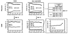
- Example 11 As shown in Table 6, in Comparative Example 10, molybdenum was not present in both the precursor and the positive electrode active material, and in Comparative Example 11, tungsten was uniformly present in both the precursor and the positive electrode active material.
- the precursor was present at a concentration of 1 mol% only in portions having a thickness of 2 ⁇ m on the outermost surface. That is, in Example 11, the average concentration of molybdenum in the precursor before firing is 1 mol%, but the average concentration of molybdenum from the outermost surface to the inner portion of 0.2 ⁇ m is 10 mol%, and the actual molybdenum is It was confirmed that most of them exist only in the 0.2 ⁇ m portion from the outermost surface to the inner side.
- the positive electrode active material in powder form (based on 1 g), poly(vinylidene fluoride), and carbon black prepared according to Examples and Comparative Examples were respectively 90:4.5: After adding to 0.4 g of N -methyl pyrrolidone at a weight ratio of 5.5, it was uniformly mixed to prepare a positive electrode slurry. The prepared positive electrode slurry was coated on aluminum foil, roll pressed, and vacuum dried to prepare a positive electrode.
- the positive electrode is manufactured by coating the positive electrode made of slurry on aluminum foil so that the loading level of the positive electrode active material is 5 mg/cm2 (aluminum foil coated with the positive electrode active material).
- the half cell was manufactured as a 2032-coin half cell (hereinafter, coin cell) using Li o as a cathode.
- a positive electrode made of a slurry was coated on an aluminum foil so that the loading level of the positive electrode active material was 8.5 mg/cm 2 to prepare a positive electrode, and graphite made of the slurry was added to the copper foil. The coating was applied so that the loading level was 6.5 mg/cm 2, and vacuum dried after roll pressing to prepare a negative electrode.
- a positive electrode, a separator (Celgard, model 2320) and a negative electrode were stacked and sealed together with the prepared electrolyte to prepare a pouch-type full cell.
- the manufactured half-cell was charged to 4.3V with a constant current of 0.5C (180 mA/g for 1C) at 30°C and discharged to 2.7V to check the recovery capacity by performing 100 cycles under the same conditions as in the charge/discharge test (hereinafter , 2.7V-4.3V).
- the positive electrode active material according to Preparation Example and the metal composite oxide (precursor) before pre-firing the positive electrode active material were confirmed to have a microstructure by SEM (Nova Nano SEM 450, FEI).
- Table 7 is a table showing capacity and cycle characteristics according to Example 1 and Comparative Example 1.
- 2A is a SEM photograph of the cathode active material according to Example 1 of the present invention
- FIG. 2B is a graph analyzing the element composition of the cathode active material precursor according to Example 1 of the present invention
- FIG. 2C is a view of Example 1 of the present invention. These are graphs that analyzed the elemental composition of the cathode active material.
- element compositions of the cathode active material precursor and the cathode active material according to Example 1 were analyzed according to the distance from the center of the particle. As shown in FIGS. 1 and 2, it can be seen that the average concentration of tungsten at the surface portion is higher than the average concentration of tungsten at the center portion, and the concentration of tungsten gradually decreases from the surface portion to the center portion.
- the cathode active material precursor according to Example 1 of the present invention is present at a concentration of 1 mol% of tungsten only in a portion having a thickness of 1 ⁇ m on the outermost surface, and there is no tungsten inside. This is because, during the manufacturing process, tungsten was added to only the outermost surface of the cathode active material precursor. On the other hand, it can be seen that tungsten diffuses into the inside after firing as shown in FIG. 2B. Even when tungsten diffused into the interior, it was confirmed that the concentration of tungsten gradually increased toward the surface portion (outermost surface). Referring to FIGS. 2A and 2B, it was confirmed that the positive electrode active material had a constant concentration inside (the core part), and the outside had a concentration gradient of nickel, cobalt, and manganese all (shell part).
- FIG. 3 is a TEM photograph and a SAED pattern of a surface portion of a positive electrode active material according to Example 1 of the present invention
- FIG. 4 is a TEM photograph and a SAED pattern of a central portion of the positive electrode active material according to Example 2 of the present invention.
- Example 1 TEM photographs were taken of the surface (shell part) and the center (core part) of the positive electrode active material according to Example 1, and the SAED pattern was analyzed.
- Example 1 it can be seen that cation ordering of lithium and transition metals was observed on the surface of the positive electrode active material particles, and the center of the particles had a layered crystal structure.
- the positive electrode active material according to Example 1 includes a first lithium layer consisting of only lithium, a first transition metal layer consisting of only a transition metal, and at least some of the lithium constituting the first lithium layer is a transition metal.
- a second lithium layer regularly substituted with, and at least a part of the first transition metal layer may include a second transition metal layer regularly substituted with lithium.
- the core portion which is the center portion, consists only of a layered crystal structure in which the first lithium layer and the first transition metal layer alternately exist, but the first lithium layer and the first transition metal layer alternate in the shell portion, which is the surface portion. It was confirmed that not only the layered crystal structure, but also an ordering structure (cation ordering, indicated by a round circle) in which the second lithium layer and the second transition metal layer are alternately and regularly provided.
- the second lithium layer lithium and transition metal are alternately arranged, in the second transition metal layer, transition metal and lithium are alternately arranged, and a lattice formed by the second lithium layer and the second transition metal layer is Includes super lattice.
- the superlattice has 6 lithium elements and 1 transition metal element.
- the first lithium layer and the Only the first diffraction point group corresponding to the grating formed by the first transition metal layer and formed by aligning one or more diffraction points having a relatively high intensity in one direction is observed, but the second lithium layer together with the first diffraction point group And one or more diffraction points corresponding to the grating formed by the second transition metal layer and having a relatively lower intensity than the diffraction points included in the first diffraction point group are aligned in one direction to further observe the second diffraction point group. It could be confirmed that it can be.
- the first diffraction point group and the second diffraction point group are alternately and regularly arranged with each other, and the first diffraction point group and the second diffraction point group are spaced apart at equal intervals. That is, in FIG. 3, an extra peak (circular representation) that cannot be indexed in the space group system of R3m is identified, and the extra peak (circular representation) is a second diffraction point group, rather than the second diffraction point group. The peak that appeared relatively bright was represented by the first group of diffraction dots.
- FIG. 5 is a graph measuring the discharge capacity of a lithium secondary battery including a positive electrode active material according to Example 1 and Comparative Example 1 of the present invention
- FIG. 6 is a graph showing the positive electrode active material according to Example 1 and Comparative Example 1 of the present invention.
- FIG. 7 is a graph measuring the differential capacity according to the number of charging and discharging of the lithium secondary battery including the positive electrode active material according to Example 1 and Comparative Example 1 of the present invention.
- FIG. 8 is a graph evaluating the thermal stability of lithium secondary batteries including positive electrode active materials according to Example 1 and Comparative Example 1 of the present invention.
- Example 1 exhibited excellent life characteristics even at 100 cycles.
- the differential capacity according to the number of charge and discharge times of lithium secondary batteries including the positive electrode active material according to Example 1 and Comparative Example 1 was measured.
- As charging and discharging is performed in the case of the lithium secondary battery including the positive electrode active material according to Comparative Example 1, it can be seen that the peak value decreases significantly between 4.1 and 4.2V.
- the peak value decreases significantly between 4.1 and 4.2V.
- the volume change amount due to contraction and expansion in the c-axis direction during the charging and discharging process is significantly reduced, thereby improving the life characteristics.
- Example 8 DSC measurement of a lithium secondary battery including the positive electrode active material according to Example 1 and Comparative Example 1 was performed.
- FIG. 7 it can be seen that the thermal properties of the positive electrode active material doped with tungsten according to Example 1 are remarkably superior compared to Comparative Example 1.
- performing tungsten doping is an efficient method of improving the thermal properties of the positive electrode active material.
- FIG. 9 is a graph showing the capacity characteristics of Examples 2 to 4 and Comparative Examples 2 to 4 of the present invention
- FIG. 10 is a graph showing the capacity characteristics of Examples 2 to 4 and Comparative Examples 2 to 4 of the present invention. This is a graph showing the cycle characteristics of Example 4.
- Comparative Example 4 when tungsten was entirely contained in an amount of 1 mol%, the capacity was relatively low compared to other Examples and Comparative Examples.
- FIG. 10 it was confirmed that the cycle characteristics of Comparative Example 4 were good. That is, as in Comparative Example 4, when tungsten is added so that the total amount of the positive electrode active material is 1 mol%, while the cycle characteristics are improved, the capacity characteristics are lowered. Comparing Comparative Example 2 containing no tungsten at all and Example 2 containing tungsten in a trace amount (0.13 mol%), it was confirmed that Example 2 exhibited similar capacity characteristics as Comparative Example 2 and at the same time significantly improved life characteristics.
- Example 4 when comparing Example 4 and Comparative Example 3 of the present invention, it was confirmed that even though the same content of tungsten (0.50 mol%) was included, Example 4 had more excellent life characteristics than Comparative Example 3. That is, it was confirmed that, in the precursor stage, the surface tungsten was provided on the outermost side, thereby exhibiting improved life characteristics even with a low concentration of tungsten.
- FIG. 11 is an SEM image showing a cross section of a precursor according to Example 6 of the present invention
- FIG. 12 is an SEM image showing a cathode active material, which is a sintered body of Example 6 and Comparative Example 5.
- the aspect ratio (ratio of the length in the a-axis direction to the length in the c-axis direction) is as the primary particles of both sides go from the center of the secondary particle to the surface. It could be confirmed that it increased. More specifically, it was confirmed that the length in the c-axis direction is almost unchanged, but the length in the a-axis direction is longer in the surface portion. In addition, it was confirmed that the shapes of the primary particles and the secondary particles in the precursor stage were almost similarly maintained in the positive electrode active material after firing at high temperature.
- the primary particles located on the surface of the secondary particles were oriented compared to Example 6 (the a-axis direction of the primary particles was oriented toward the center of the secondary particles. ), and it was confirmed that the primary particles were not formed in the form of a rod shape.
- the primary particles constituting the secondary particles after firing have an increased aspect ratio from the center of the secondary particles to the surface.
- FIG. 13 is a graph showing the capacity characteristics of Examples 5, 6, and 5 of the present invention
- FIG. 14 is a graph showing the cycle characteristics of Examples 5, 6, and 5 of the present invention. to be.
- Table 10 is a table showing electrochemical values including capacity characteristics and cycle characteristics of Examples 2 and 6 and Comparative Examples 2 and 5.
- 15 is a graph showing the capacity characteristics of Example 2, Example 6, and Comparative Example 5
- FIG. 16 is a graph showing the cycle characteristics of Examples 2 and 6, Comparative Example 2, and Comparative Example 5.
- Example 2 is a positive electrode active material doped with 1 mol% of tungsten only in a portion having an outermost thickness of 0.25 ⁇ m in a precursor
- Example 6 is a positive electrode active material doped with 1 mol% of tungsten only in a portion having an outermost thickness of 0.2 ⁇ m.
- Comparative Example 2 and Example 2 in which cobalt and manganese were contained at 5:5 were compared, and carried out with Comparative Example 5 in which cobalt and manganese were contained at 7:3.
- Comparative Example 6 it was confirmed that the cycle characteristics were excellent when tungsten was doped on the outermost surface of both sides.
- Example 6 had better cycle characteristics than Example 2.
- the higher the cobalt content the more effectively improved the cycle characteristics, which is that cobalt whose concentration increases toward the surface portion and tungsten whose concentration increases toward the surface portion have the highest It is believed that this is because the secondary particles interact with each other on the surface of the secondary particles to stabilize the crystal structure to prevent the occurrence of microcracks and the like during the cycle, thereby preventing the penetration of the electrolyte.
- FIG. 17 is a graph showing the capacity characteristics of Examples 7 to 9 and Comparative Examples 6 and 7 of the present invention
- FIG. 18 is a graph showing the capacity characteristics of Examples 7 to 9 and Comparative Example 6 of the present invention. It is a graph showing the cycle characteristics of Example 7.
- Comparative Example 7 is that tungsten is entirely doped in the precursor, and contains 0.75 mol%, but Examples 7 to 9 are tungsten doped mainly on the outermost side of the precursor, and the content of tungsten is higher than that of Comparative Example 7. It was confirmed that the cycle characteristics were excellent despite being relatively low.
- Table 12 is a table showing electrochemical data for Example 10 and Comparative Example 8.
- Example 10 NCM NCW 90 (90 7.5 2 0.5) was doped with tungsten on the outermost side in the step of preparing a precursor
- Comparative Example 8 NCW NCM 90 (89.5 5 5 0.5) was the best in the step of preparing a precursor). The inside was doped with tungsten, and electrochemical evaluation was performed in each of 2.
- Fig. 19 is a graph showing the capacity characteristics of Example 10 and Comparative Example 8
- Fig. 20 is a graph showing the cycle characteristics of Example 10 and Comparative Example 8. This is the graph shown.
- Example 10 had better cycle characteristics than Comparative Example 8. Even when doping with the same amount of tungsten, doping on the outside rather than the inside of the precursor is more effective for the cycling characteristics. It was confirmed that it works. This is believed to be due to the fact that by doping tungsten on the outermost side, the outermost crystal structure can be more stabilized, thereby preventing penetration of the electrolyte from the outside during the course of the cycle. As another aspect, the tungsten doped on the outermost side of the secondary particles in the precursor stage can allow the primary particles constituting the secondary particles to develop a rod shape shape more on the outermost side of the secondary particles. It is judged because the orientation of the primary particles on the outer surface can be further improved.
- Table 13 shows a positive electrode active material that is a CSG (Core Shell Gradient) formed such that the core portion has a constant concentration of nickel, cobalt, and manganese, and the shell portion has a concentration gradient of at least one of nickel, cobalt, and manganese.
- Tungsten was doped only on the outermost shell portion, and in Comparative Example 9, tungsten was doped to be uniform throughout. The average tungsten doping amount of Example 10 and Comparative Example 9 was the same as 0.5 mol%.
- 21 is a graph showing the capacity characteristics of Example 10 and Comparative Example 9
- FIG. 22 is a graph showing the cycle characteristics of Example 10 and Comparative Example 9.
- Example 10 was more excellent in cycle characteristics. That is, even in the case of the CSG type positive electrode active material, it was confirmed that doping the outermost shell is more effective in the cycle characteristics than doping the tungsten uniformly overall.
- Table 14 shows the electrochemical properties of Example 11, Comparative Example 10, and Comparative Example 11.
- 23 is an SEM image showing a cross-section of the precursor of Example 11
- FIG. 24 is an SEM image showing a cross-section of a cathode active material, which is a fired body of Example 11.
- 25A and 25B are SEM images of the sintered cathode active material of Comparative Example 11 (left) and Example 11 (right).
- 26 is a graph showing the element composition in the positive electrode active material that is a precursor and a sintered body of Comparative Examples 10 and 11.
- 27 is a graph showing the capacity characteristics of Example 11, Comparative Example 10, and Comparative Example 11, and
- FIG. 28 is a graph showing the cycle characteristics of Example 11, Comparative Example 10, and Comparative Example 11.
- Example 11 in which molybdenum (Mo) was doped only on the outermost part, it was confirmed that the rod shape shape and orientation of the primary particles were clearly shown in both the precursor and the cathode active material, which is a firing. In addition, in Example 11, it was confirmed that the primary particles in the shape of a rod-shape visible in the precursor appeared in the positive electrode active material as it was after firing.
- Mo molybdenum
- Example 11 in which molybdenum was doped uniformly as a whole and Example 11 doped on the outermost side, the shapes of the primary particles and secondary particles of Example 11 of the same amount of molybdenum were relatively similar. could be confirmed.
- Example 11 had a concentration gradient in a direction in which the concentration of molimdenium increased toward the outermost side after firing.
- Example 11 was superior to Comparative Example 10 and Comparative Example 11.
- the cycle characteristics of Example 11 doped on the outermost side were more effective than Comparative Example 11, which was uniformly doped as a whole.
Landscapes
- Chemical & Material Sciences (AREA)
- Organic Chemistry (AREA)
- Chemical Kinetics & Catalysis (AREA)
- Electrochemistry (AREA)
- General Chemical & Material Sciences (AREA)
- Inorganic Chemistry (AREA)
- Engineering & Computer Science (AREA)
- Composite Materials (AREA)
- Materials Engineering (AREA)
- Manufacturing & Machinery (AREA)
- Battery Electrode And Active Subsutance (AREA)
Abstract
본 발명은 복수개의 제1 일차입자의 집단으로 이루어진 제1 이차입자를 포함하는 양극활물질 전구체에서, 상기 양극활물질 전구체는 화학식 1로 이루어진 제1 중심부와, 화학식 2로 이루어진 제1 표면부를 포함하고, 상기 양극활물질 전구체의 평균반경에 대한 상기 제1 표면부의 두께는 2% 내지 20%의 길이로 구비되는 것을 포함하는 양극활물질 전구체와, 이를 포함하는 양극활물질에 관한 것이다.
Description
본 출원은 양극활물질 및 그 제조 방법에 관련된 것으로, 보다 상세하게는, 이종원소이 도핑된 표면부를 갖는 양극활물질, 그 제조 방법, 및 이를 포함하는 리튬 이차 전지에 관련된 것이다.
스마트폰, MP3 플레이어, 태블릿 PC와 같은 휴대용 모바일 전자 기기의 발전으로, 전기 에너지를 저장할 수 있는 이차 전지에 대한 수요가 폭발적으로 증가하고 있다. 특히, 전기 자동차, 중대형 에너지 저장 시스템, 및 고 에너지 밀도가 요구되는 휴대 기기의 등장으로, 리튬 이차 전지에 대한 수요가 증가하고 있는 실정이다.
이러한, 리튬 이차 전지에 대한 수요의 증가와 함께 리튬 이차 전지에 사용되는 양극활물질의 특성을 향상시키기 위한 다양한 연구 개발이 진행되고 있다. 예를 들어, 대한민국 특허공개공보 10-2014-0119621(출원번호 10-2013-0150315)에는 리튬 과량 양극활물질 제조용 전구체를 이용하여, 전구체에서 치환되는 금속의 종류 및 조성을 조절하고, 첨가되는 금속의 종류 및 첨가량을 조절하여, 고전압 용량 및 장수명 특성을 갖는 이차전지가 개시되어 있다.
본 출원이 해결하고자 하는 일 기술적 과제는 고함량의 니켈을 포함하여 용량특성과 함께 수명특성이 향상된 고용량의 양극활물질, 그 제조 방법, 및 이를 포함하는 리튬 이차 전지를 제공하는 데 있다.
본 출원이 해결하고자 하는 다른 기술적 과제는 신규한 방법을 이용하여 양극활물질을 제조함으로써, 양극활물질의 표면부측의 결정구조를 내부와는 다르게 구비시킴으로써, 장수명의 양극활물질, 그 제조 방법, 및 이를 포함하는 리튬 이차 전지를 제공하는 데 있다.
본 출원이 해결하고자 하는 또 다른 기술적 과제는 고안정성의 양극활물질, 그 제조 방법, 및 이를 포함하는 리튬 이차 전지를 제공하는 데 있다.
본 출원이 해결하고자 하는 또 다른 기술적 과제는 높은 방전용량을 가지면서 동시에 충방전 횟수에 따른 수명 저하 특성이 최소화된 양극활물질, 그 제조 방법, 및 이를 포함하는 리튬 이차 전지를 제공하는 데 있다.
본 출원이 해결하고자 하는 기술적 과제는, 전술한 것에 제한되지 않는다.
본 발명의 일측면에 따르면, 본 발명의 실시예들은 복수개의 제1 일차입자의 집단으로 이루어진 제1 이차입자를 포함하는 양극활물질 전구체에서, 상기 양극활물질 전구체는 하기 화학식 1로 이루어진 제1 중심부와, 하기 화학식 2로 이루어진 제1 표면부를 포함하고, 상기 양극활물질 전구체의 평균반경에 대한 상기 제1 표면부의 두께는 2% 내지 20%의 길이로 구비되는 것을 포함하는 양극활물질 전구체를 포함한다.
<화학식 1>
Ni1-xM1x(OH)2
<화학식 2>
Ni1-y-zM1yM2z(OH)2
여기서, M1은 코발트(Co), 망간(Mn), 알루미늄(Al) 또는 이들의 혼합물이고, M2는 텅스텐(W), 몰리브덴(Mo), 탄탈륨(Ta), 니오븀(Nb), 하프늄(Hf), 실리콘(Si), 주석(Sn), 지르코늄(Zr), 칼슘(Ca), 게르마늄(Ge), 갈륨(Ga), 인듐(In), 루테늄(Ru), 텔루륨(Te), 안티모니(Sb), 철(Fe), 크롬(Cr), 바나듐(V) 및 티타늄(Ti) 또는 이들의 혼합물이고, 0≤x≤0.2, 0≤y≤0.2, 0.005≤z≤0.1이다.
일 실시예에 있어서, 상기 제1 일차입자는 c축 방향의 길이에 대한 a축 방향의 길이가 다르게 구비되는 것을 포함하되, 상기 제1 표면부에 구비되는 제1 일차입자의 a축 방향의 길이는 상기 제1 중심부에 구비되는 제1 일차입자의 a축 방향의 길이보다 더 길게 구비되는 것을 포함할 수 있다.
일 실시예에 있어서, 상기 제1 중심부와 제1 표면부는 리튬만으로 이루어진 제1 리튬층(Li layers)과 전이금속만으로 이루어진 제1 전이금속층(transition metal layers)을 포함하는 암염 층상구조(R-3m 공간군)를 갖는 것을 포함할 수 있다.
본 발명의 다른 측면에 따르면, 본 발명은 전술한 양극활물질 전구체를 리튬화합물과 혼합한 후 소성하여 제조된 양극활물질로, 상기 양극활물질은 복수개의 제2 일차입자의 집단으로 이루어진 제2 이차입자를 포함하고, 상기 양극활물질은 상기 양극활물질의 중심에 인접한 부분인 제2 중심부와, 상기 제2 중심부를 감싸도록 상기 양극활물질의 외면에 구비되는 제2 표면부를 포함하고, 상기 제2 중심부 및 상기 제2 표면부는 리튬, 니켈, 산소, M1 및 M2을 포함하고, 상기 M1은 코발트(Co), 망간(Mn), 알루미늄(Al) 또는 이들의 혼합물이고, 상기 M2는 텅스텐(W), 몰리브덴(Mo), 탄탈륨(Ta), 니오븀(Nb), 하프늄(Hf), 실리콘(Si), 주석(Sn), 지르코늄(Zr), 칼슘(Ca), 게르마늄(Ge), 갈륨(Ga), 인듐(In), 루테늄(Ru), 텔루륨(Te), 안티모니(Sb), 철(Fe), 크롬(Cr), 바나듐(V) 및 티타늄(Ti) 또는 이들의 혼합물이며, 상기 M2는 0.5mol% 내지 10mol%인 것을 포함하는 양극활물질을 포함한다.
일 실시예에 있어서, 상기 M2는 0.5mol% 내지 2mol%인 것을 포함할 수 있다.
일 실시예에 있어서, 상기 제2 중심부의 M2의 농도는 상기 제2 표면부의 M2의 농도보다 낮게 구비될 수 있다.
일 실시예에 있어서, 상기 제2 표면부에서 M2의 농도는 상기 제2 중심부에서 외측으로 멀어질수록 농도가 증가하도록 농도구배를 갖는 것을 포함할 수 있다.
일 실시예에 있어서, 상기 양극활물질은 하기 화학식 3으로 표시될 수 있다.
<화학식 3>
LiaNi1-b-cM1bM2cO2-d
여기서, M1은 코발트(Co), 망간(Mn), 알루미늄(Al) 또는 이들의 혼합물이고, M2는 텅스텐(W), 몰리브덴(Mo), 탄탈륨(Ta), 니오븀(Nb), 하프늄(Hf), 실리콘(Si), 주석(Sn), 지르코늄(Zr), 칼슘(Ca), 게르마늄(Ge), 갈륨(Ga), 인듐(In), 루테늄(Ru), 텔루륨(Te), 안티모니(Sb), 철(Fe), 크롬(Cr), 바나듐(V) 및 티타늄(Ti) 또는 이들의 혼합물이고, 0.8≤a≤1.1, 0≤b≤0.2, 0.001≤c≤0.05, 0≤d≤2이다.
일 실시예에 있어서, 상기 양극활물질의 평균반경에 대한 상기 제2 표면부의 두께는 2% 내지 20%의 길이로 구비되는 것을 포함할 수 있다.
일 실시예에 있어서, 상기 양극활물질은 리튬만으로 이루어진 제1 리튬층(Li layers)과, 전이금속만으로 이루어진 제1 전이금속층(transition metal layers), 상기 제1 리튬층을 구성하는 리튬 중 적어도 일부가 전이금속으로 규칙적으로 치환된 제2 리튬층 및 상기 제1 전이금속층의 적어도 일부가 리튬으로 규칙적으로 치환된 제2 전이금속층을 포함하며, 상기 제2 중심부 및 제2 표면부는 제1 리튬층과 제1 전이금속층을 포함하되, 상기 제2 표면부는 상기 제2 리튬층과 제2 전이금속층이 교대로 그리고 규칙적으로 구비되는 오더링 구조(cation ordering)를 더 포함할 수 있다.
일 실시예에 있어서, 상기 제2 리튬층과 상기 제2 전이금속층에 의하여 형성된 격자는 상기 제1 리튬 층과 상기 제1 전이금속 층에 의하여 형성되는 격자보다 2배수로 a축이 증가되는 초격자 (superlattice)를 포함하고, 상기 초격자는, 6개의 리튬 원소 및 1개의 전이금속 원소를 갖는 것을 포함할 수 있다.
일 실시예에 있어서, 상기 제2 일차입자는 c축 방향의 길이에 대한 a축 방향의 길이가 다르게 구비는 것을 포함하되, 상기 제2 표면부에 구비되는 일차입자의 a축 방향의 길이는 상기 제2 중심부에 구비되는 일차입자의 a축 방향의 길이보다 더 길게 구비되는 것을 포함할 수 있다.
일 실시예에 있어서, 상기 제2 일차입자는 c축 방향의 길이에 대한 a축 방향의 길이가 다르게 구비는 것을 포함하되, 상기 제2 일차입자는 상기 제2 중심부에서 상기 제2 표면부로 갈수록 상기 c축 방향의 길이에 대한 a축 방향의 길이인 종횡비가 증가하도록 구비될 수 있다.
일 실시예에 있어서, 상기 양극활물질은 상기 니켈, M1의 농도가 일정하게 구비되는 농도유지부와, 상기 니켈, M1 중 적어도 어느 하나 이상의 농도가 농도구배를 갖는 농도구배부를 포함하고, 상기 M2의 농도는 상기 농도유지부와 상기 농도구배부에서 농도구배를 갖도록 구비될 수 있다.
일 실시예에 있어서, 상기 M2는 상기 농도구배부에서의 상기 M2의 평균농도가 상기 농도유지부에서의 상기 M2의 평균농도보다 더 높게 구비될 수 있다.
일 실시예에 있어서, 상기 농도유지부는 상기 제2 중심부에 포함되고, 상기 농도구배부는 상기 제2 표면부에 포함되며, 상기 농도구배부에서 상기 니켈과 상기 M2는 상기 양극활물질의 내부에서 표면으로 갈 수록 농도가 감소하도록 구비되고, 상기 M1은 상기 양극활물질의 내부에서 표면으로 갈 수록 농도가 증가하도록 구비되고, 상기 M1은 Co(코발트)를 포함할 수 있다.
본 발명의 또 다른 측면에 따르면, 전술한 양극활물질을 포함하는 이차전지용 양극을 포함한다.
또한, 상기 양극; 그래파이트 또는 리튬메탈로 이루어지는 음극; 및 전해액을 포함하는 리튬이차전지를 포함할 수 있다.
본 발명의 그 외의 측면에 따르면, 전술한 리튬이차전지를 단위셀로 포함하는 전지모듈을 포함한다.
또한, 상기 전지모듈을 포함하는 전지팩으로, 상기 전지팩은 중대형 디바이스의 전원으로 사용되고, 상기 중대형 디바이스는 전기자동차, 하이브리드 전기자동차, 플러그 인 하이브리드 전기자동차 및 전력 저장용 시스템으로 이루어진 군에서 선택되는 것인 전지팩을 포함할 수 있다.
이상 살펴본 바와 같은 본 발명에 따르면, 본 발명에 따른 양극활물질은, 복수의 일차입자가 응집되어 형성된 이차입자를 포함하고, 상기 이차입자는 고함량의 니켈과 함께 이종원소가 도핑되어 구비되는 것을 포함할 수 있다.
상기 이종원소는 상기 일차입자의 형태, 일자입자의 방향성 등을 제어할 수 있으며, 이에 의하여 높은 방전용량과 함께, 장기간 안정적으로 사용이 가능한 양극활물질을 제공할 수 있다.
또한, 본 발명에 따른 양극활물질은 이종원소를 도핑함으로써 고함량의 니켈을 포함하는 양극활물질의 사이클특성을 향상시키되, 동시에 신규한 방법에 의하여 도핑시킴으로써, 종래보다 낮은 함량의 이종원소를 이용하므로 용량특성이 저하되는 것을 방지하고 동시에 사이클특성이 우수하게 향상된다.
도 1a는 본 발명의 실시예에 따른 양극활물질의 단면의 모식도이다.
도 1b는 본 발명의 실시예에 따른 양극활물질에서 리튬이온의 이동을 개략적으로 나타낸 도면이다.
도 2a는 본 발명의 실시예 1에 따른 양극활물질의 SEM 사진이다.
도 2b는 본 발명의 실시예 1에 따른 양극활물질 전구체의 원소조성을 분석한 그래프이다.
도 2c는 본 발명의 실시예 1의 양극활물질의 원소조성을 분석한 그래프들이다.
도 3은 본 발명의 실시 예 1에 따른 양극활물질의 표면부의 TEM 사진 및 SAED pattern이다.
도 4는 본 발명의 실시 예 2에 따른 양극활물질의 중심부의 TEM 사진 및 SAED pattern이다.
도 5는 본 발명의 실시예 1 및 비교예 1에 따른 양극활물질을 포함하는 리튬 이차 전지의 방전 용량을 측정한 그래프이다.
도 6은 본 발명의 실시예 1 및 비교예 1에 따른 양극활물질을 포함하는 리튬 이차 전지의 수명 특성을 측정한 그래프이다.
도 7은 본 발명의 실시예 1 및 비교예 1에 따른 양극활물질을 포함하는 리튬 이차 전지의 충방전 횟수에 따른 미분 용량을 측정한 그래프이다.
도 8은 본 발명의 실시예 1 및 비교예 1에 따른 양극활물질을 포함하는 리튬 이차 전지의 열적 안정성을 평가한 그래프이다.
도 9는 본 발명의 실시예 2 내지 실시예 4와, 비교예 2 내지 비교예 4의 용량특성을 나타낸 그래프이다.
도 10은 본 발명의 실시예 2 내지 실시예 4와, 비교예 2 내지 비교예 4의 사이클특성을 나타낸 그래프이다.
도 11은 본 발명의 실시예 6에 따른 전구체의 단면을 나타낸 SEM 이미지이다.
도 12는 실시예 6과, 비교예 5의 소성체인 양극활물질을 나타낸 SEM이미지이다.
도 13은 본 발명의 실시예 5, 실시예 6과, 비교예 5의 용량특성을 나타낸 그래프이다.
도 14는 본 발명의 실시예 5, 실시예 6과, 비교예 5의 사이클특성을 나타낸 그래프이다.
도 15는 실시예 2, 실시예 6과 비교예 5의 용량특성을 나타낸 그래프이다.
도 16은 실시예 2, 실시예 6과 비교예 2, 비교예 5의 사이클특성을 나타낸 그래프이다.
도 17은 본 발명의 실시예 7 내지 실시예 9와, 비교예 6 및 비교예 7의 용량특성을 나타낸 그래프이다.
도 18은 본 발명의 실시예 7 내지 실시예 9와, 비교예 6 및 비교예 7의 사이클특성을 나타낸 그래프이다.
도 19는 실시예 10, 비교예 8의 용량특성을 나타낸 그래프이다.
도 20은 실시예 10, 비교예 8의 사이클특성을 나타낸 그래프이다.
도 21은 실시예 10 및 비교예 9의 용량특성을 나타낸 그래프이다.
도 22는 실시예 10 및 비교예 9의 사이클특성을 나타낸 그래프이다.
도 23은 실시예 11의 전구체의 단면을 나타낸 SEM 이미지이다.
도 24는 실시예 11의 소성체인 양극활물질의 단면을 나타낸 SEM 이미지이다.
도 25a 및 도 25b는 비교예 11(좌측)과 실시예 11(우측)의 소성체인 양극활물질의 SEM 이미지이다.
도 26는 비교예 10 및 실시예 11의 전구체 및 소성체인 양극활물질에서의 원소조성을 나타낸 그래프이다.
도 27은 실시예 11, 비교예 10 및 비교예 11의 용량특성을 나타낸 그래프이다.
도 28은 실시예 11, 비교예 10 및 비교예 11의 사이클특성을 나타낸 그래프이다.
기타 실시예들의 구체적인 사항들은 상세한 설명 및 도면들에 포함되어 있다.
본 발명의 이점 및 특징, 그리고 그것들을 달성하는 방법은 첨부되는 도면과 함께 상세하게 후술되어 있는 실시예들을 참조하면 명확해질 것이다. 그러나 본 발명은 이하에서 개시되는 실시예들에 한정되는 것이 아니라 서로 다른 다양한 형태로 구현될 수 있으며, 이하의 설명에서 달리 명시되지 않는 한, 본 발명에 성분, 반응 조건, 성분의 함량을 표현하는 모든 숫자, 값 및/또는 표현은, 이러한 숫자들이 본질적으로 다른 것들 중에서 이러한 값을 얻는 데 발생하는 측정의 다양한 불확실성이 반영된 근사치들이므로, 모든 경우 "약"이라는 용어에 의해 수식되는 것으로 이해되어야 한다. 또한, 본 기재에서 수치범위가 개시되는 경우, 이러한 범위는 연속적이며, 달리 지적되지 않는 한 이러한 범위의 최소값으로부터 최대값이 포함된 상기 최대값까지의 모든 값을 포함한다. 더 나아가, 이러한 범위가 정수를 지칭하는 경우, 달리 지적되지 않는 한 최소값으로부터 최대값이 포함된 상기 최대값까지를 포함하는 모든 정수가 포함된다
또한, 본 발명에서 범위가 변수에 대해 기재되는 경우, 상기 변수는 상기 범위의 기재된 종료점들을 포함하는 기재된 범위 내의 모든 값들을 포함하는 것으로 이해될 것이다. 예를 들면, "5 내지 10"의 범위는 5, 6, 7, 8, 9, 및 10의 값들뿐만 아니라 6 내지 10, 7 내지 10, 6 내지 9, 7 내지 9 등의 임의의 하위 범위를 포함하고, 5.5, 6.5, 7.5, 5.5 내지 8.5 및 6.5 내지 9 등과 같은 기재된 범위의 범주에 타당한 정수들 사이의 임의의 값도 포함하는 것으로 이해될 것이다. 예를 들면, "10% 내지 30%"의 범위는 10%, 11%, 12%, 13% 등의 값들과 30%까지를 포함하는 모든 정수들 뿐만 아니라 10% 내지 15%, 12% 내지 18%, 20% 내지 30% 등의 임의의 하위 범위를 포함하고, 10.5%, 15.5%, 25.5% 등과 같이 기재된 범위의 범주 내의 타당한 정수들 사이의 임의의 값도 포함하는 것으로 이해될 것이다.
일 실시예에서 일차입자, 이차입자 등과 같은 각종 입자들의 크기, 입경에 관해서는, 계측법에 의해 수치화하여 집단의 평균 크기를 표현하는 방법이 있지만, 범용적으로 사용되는 것으로 분포의 최대값을 나타내는 모든 직경, 적분 분포 곡선의 중앙값에 상당하는 메디안 직경, 각종 평균 직경(수평균, 길이 평균, 면적 평균, 질량 평균, 체적 평균 등)등이 있고 본 발명에 있어서는 특별히 언급하지 않는 한 평균 크기, 평균 입경이란 수평균 크기, 직경이고, D50(분포율이 50%되는 지점의 입경)을 측정한 것을 의미한다.
본 발명의 일측면에 따르면, 본 발명은 복수개의 제1 일차입자의 집단으로 이루어진 제1 이차입자를 포함하는 양극활물질 전구체에서, 상기 양극활물질 전구체는 하기 화학식 1로 이루어진 제1 중심부와, 하기 화학식 2로 이루어진 제1 표면부를 포함하고, 상기 양극활물질 전구체의 평균반경에 대한 상기 제1 표면부의 두께는 2% 내지 20%의 길이로 구비되는 것을 포함하는 양극활물질 전구체을 포함한다.
<화학식 1>
Ni1-xM1x(OH)2
<화학식 2>
Ni1-y-zM1yM2z(OH)2
여기서, M1은 코발트(Co), 망간(Mn), 알루미늄(Al) 또는 이들의 혼합물이고, M2는 텅스텐(W), 몰리브덴(Mo), 탄탈륨(Ta), 니오븀(Nb), 하프늄(Hf), 실리콘(Si), 주석(Sn), 지르코늄(Zr), 칼슘(Ca), 게르마늄(Ge), 갈륨(Ga), 인듐(In), 루테늄(Ru), 텔루륨(Te), 안티모니(Sb), 철(Fe), 크롬(Cr), 바나듐(V) 및 티타늄(Ti) 또는 이들의 혼합물이고, 0≤x≤0.2, 0≤y≤0.2, 0.005≤z≤0.1이다.
상기 제1 일차입자는 c축 방향의 길이에 대한 a축 방향의 길이가 다르게 구비되는 것을 포함하되, 상기 제1 표면부에 구비되는 제1 일차입자의 a축 방향의 길이는 상기 제1 중심부에 구비되는 제1 일차입자의 a축 방향의 길이보다 더 길게 구비되는 것을 포함할 수 있다.
본 실시예에 따른 양극활물질 전구체에서, 제1 이차입자는 대략 구형으로 이루어질 수 있고, 상기 제1 일차입자는 c축 방향의 길이에 대한 a축 방향의 길이가 다르게 구비되는 로드쉐입(rod shape)의 형상으로 이루어질 수 있다. 상기 제1 일차입자는 적어도 일부는 방사형 방향으로 정렬될 수 있으며, 상기 제1 일차입자는 상기 양극활물질의 중심에서 표면으로 향하는 방향으로 a축 방향이 제1 이차입자의 중심을 향하도록 배향할 수 있다. 또한, 상기 제1 일차입자는 제1 이차입자의 중심부보다 표면부에서 보다 배향상을 갖도록 구비될 수 있으며, 중심부보다 표면부에서 a축 방향의 길이가 더 길게 구비될 수 있다. 구체적으로, 상기 제1 일차입자는 중심부에서 표면부를 향하는 방향으로 a축 방향의 길이가 증가되는 형태로 구비될 수 있다.
본 발명의 실시예에 따른 양극활물질 전구체는, 제1 중심부와 제1 표면부가 서로 상이한 화합식으로 이루어질 수 있으며, 상기 제1 중심부와 제1 표면부는 리튬만으로 이루어진 제1 리튬층(Li layers)과 전이금속만으로 이루어진 제1 전이금속층(transition metal layers)을 포함하는 암염 층상구조(R-3m 공간군)를 갖는 것을 포함할 수 있다. 예컨대, 상기 양극활물질 전구체는 제1 중심부와 제2 표면부가 상이한 화합물로 구비됨에도 동일한 결정구조인 암염 층상구조로 이루어질 수 있다. 또한, 제1 중심부와 제1 표면부가 상이한 화학식으로 이루어짐에도, 상기 제1 중심부와 제2 표면부에 구비되는 제1 일차입자가 서로 이질적인 형상으로 구비되는 것이 아닌, 로드쉐입의 형상으로 연속성을 갖도록 구비될 수 있다.
도 1a는 본 발명의 실시예에 따른 양극활물질의 단면의 모식도이고, 도 1b는 본 발명의 실시예에 따른 양극활물질에서 리튬이온의 이동을 개략적으로 나타낸 도면이다.
도 1a 및 도 1b를 참조하면, 본 발명은 전술한 양극활물질 전구체를 리튬화합물과 혼합한 후 소성하여 제조된 양극활물질로, 상기 양극활물질은 복수개의 제2 일차입자(10)의 집단으로 이루어진 제2 이차입자(100)를 포함하고, 상기 양극활물질은 상기 양극활물질의 중심에 인접한 부분인 제2 중심부와, 상기 제2 중심부를 감싸도록 상기 양극활물질의 외면에 구비되는 제2 표면부를 포함할 수 있다.
상기 제2 중심부 및 상기 제2 표면부는 리튬, 니켈, 산소, M1 및 M2을 포함하고, 상기 M1은 코발트(Co), 망간(Mn), 알루미늄(Al) 또는 이들의 혼합물이고, 상기 M2는 텅스텐(W), 몰리브덴(Mo), 탄탈륨(Ta), 니오븀(Nb), 하프늄(Hf), 실리콘(Si), 주석(Sn), 지르코늄(Zr), 칼슘(Ca), 게르마늄(Ge), 갈륨(Ga), 인듐(In), 루테늄(Ru), 텔루륨(Te), 안티모니(Sb), 철(Fe), 크롬(Cr), 바나듐(V) 및 티타늄(Ti) 또는 이들의 혼합물이며, 상기 M2는 0.5mol% 내지 10mol%인 것을 포함할 수 있다.
구체적으로는, 상기 M2는 대략 0.55mol% 내지 10mol%, 대략 0.6mol% 내지 10mol%, 대략 0.65mol% 내지 10mol%, 대략 0.7mol% 내지 10mol%, 대략 0.75mol% 내지 10mol%, 대략 0.8mol% 내지 10mol%, 대략 0.85mol% 내지 10mol%, 대략 0.9mol% 내지 10mol%, 대략 0.95mol% 내지 10mol%이거나, 또는 대략 0.5mol% 내지 9.5mol%, 대략 0.5mol% 내지 9mol%, 대략 0.5mol% 내지 8.5mol%, 대략 0.5mol% 내지 8mol%, 대략 0.5mol% 내지 7.5mol%, 대략 0.5mol% 내지 7mol%, 대략 0.5mol% 내지 6.5mol%, 대략 0.5mol% 내지 6mol%, 대략 0.5mol% 내지 5.5mol%, 대략 0.5mol% 내지 5mol%일 수 있다. 또한, 상기 M2는 대략 1mol% 내지 10mol%, 대략 2mol% 내지 10mol%, 대략 3mol% 내지 10mol%, 대략 4mol% 내지 10mol%, 대략 5mol% 내지 10mol%일 수 있다. 보다 구체적으로는, 상기 M2는 0.5mol% 내지 2mol%일 수 있다.
상기 양극활물질에서, 상기 제2 중심부의 M2의 농도는 상기 제2 표면부의 M2의 농도보다 낮게 구비될 수 있다. 구체적으로, 상기 제2 표면부에서 M2의 농도는 상기 제2 중심부에서 외측으로 멀어질수록 농도가 증가하도록 농도구배를 갖을 수 있다.
상기 양극활물질은 하기 화학식 3으로 표시될 수 있다.
<화학식 3>
LiaNi1-b-cM1bM2cO2-d
여기서, M1은 코발트(Co), 망간(Mn), 알루미늄(Al) 또는 이들의 혼합물이고, M2는 텅스텐(W), 몰리브덴(Mo), 탄탈륨(Ta), 니오븀(Nb), 하프늄(Hf), 실리콘(Si), 주석(Sn), 지르코늄(Zr), 칼슘(Ca), 게르마늄(Ge), 갈륨(Ga), 인듐(In), 루테늄(Ru), 텔루륨(Te), 안티모니(Sb), 철(Fe), 크롬(Cr), 바나듐(V) 및 티타늄(Ti) 또는 이들의 혼합물이고, 0.8≤a≤1.1, 0≤b≤0.2, 0.001≤c≤0.05, 0≤d≤2이다.
구체적으로, b는 0≤b≤0.18, 0≤b≤0.15, 0≤b≤0.13, 0≤b≤0.1, 0≤b≤0.07, 0≤b≤0.05 또는 0≤b≤0.03일 수 있고, c는 0.001≤c≤0.045, 0.001≤c≤0.04, 0.001≤c≤0.035, 0.001≤c≤0.03, 0.001≤c≤0.025, 0.001≤c≤0.02, 0.001≤c≤0.015, 또는 0.001≤c≤0.012일 수 있다.
상기 양극활물질의 평균반경에 대한 상기 제2 표면부의 두께는 2% 내지 20%의 길이로 구비될 수 있다. 구체적으로, 상기 제2 표면부의 두께는, 대략 2.5% 내지 20%, 대략 3% 내지 20%, 대략 4% 내지 20%, 대략 5% 내지 20%, 대략 6% 내지 20%, 대략 7% 내지 20%, 대략 8% 내지 20%, 대략 9% 내지 20%, 대략 10% 내지 20%이거나, 또는 대략 2% 내지 19%, 대략 2% 내지 18%, 대략 2% 내지 17%, 대략 2% 내지 16%, 대략 2% 내지 15%, 대략 2% 내지 14%, 대략 2% 내지 13%, 대략 2% 내지 12%, 대략 2% 내지 11%, 대략 2% 내지 10%일 수 있다.
상기 양극활물질은 리튬만으로 이루어진 제1 리튬층(Li layers)과, 전이금속만으로 이루어진 제1 전이금속층(transition metal layers), 상기 제1 리튬층을 구성하는 리튬 중 적어도 일부가 전이금속으로 규칙적으로 치환된 제2 리튬층 및 상기 제1 전이금속층의 적어도 일부가 리튬으로 규칙적으로 치환된 제2 전이금속층을 포함하며, 상기 제2 중심부 및 제2 표면부는 제1 리튬층과 제1 전이금속층을 포함하되, 상기 제2 표면부는 상기 제2 리튬층과 제2 전이금속층이 교대로 그리고 규칙적으로 구비되는 오더링 구조(cation ordering)를 더 포함할 수 있다.
상기 제2 리튬층과 상기 제2 전이금속층에 의하여 형성된 격자는 상기 제1 리튬 층과 상기 제1 전이금속 층에 의하여 형성되는 격자보다 2배수로 a축이 증가되는 초격자 (superlattice)를 포함하고, 상기 초격자는, 6개의 리튬 원소 및 1개의 전이금속 원소를 갖는 것을 포함할 수 있다.
구체적으로, 본 발명의 실시예에 따른 양극활물질 전구체에서는, 제1 중심부와 제1 표면부는 제1 리튬층과 제1 전이금속층만으로 이루어진다. 이때, 상기 제1 중심부와 제1 표면부는 서로 다른 화학식으로 이루어진다. 구체적으로, 상기 양극활물질 전구체에서, 상기 제1 중심부에는 이종원소가 도핑되어 있지 않은 반면, 상기 제1 표면부에서는 이종원소가 도핑되어 있다.
반면, 상기 양극활물질 전구체를 소성한 후 제조된 양극활물질에서는 상기 제2 중심부와 제2 표면부 사이는 화학식은 대략 유사하게 구비될 수 있으며, 구체적으로는 상기 양극활물질 전체적으로 상기 양극활물질을 구성하는 화합물을 적어도 일부분에서 농도구배를 갖거나, 혹은 적어도 일부분에서 농도가 일정한 부분을 갖거나, 혹은 전체적으로 농도구배를 갖거나, 혹은 전체적으로 농도가 제어되지 않은 상태인 벌크(bulk)로 구비될 수 있다.
상기 제2 표면부에만 있던 이종원소는 상기 제2 중심부로 확산되고 상기 이종원소는 상기 제2 중심부의 적어도 일부 이상에서 상기 제2 표면부를 거쳐서 농도구배를 갖도록 구비될 수 있다. 구체적으로, 상기 양극활물질 전구체에서 상기 제1 표면부에만 도핑된 이종원소는 상기 양극활물질에서는 상기 제2 중심부와 제2 표면부 양측에 모두 구비될 수 있다. 보다 구체적으로는, 상기 양극활물질에서 상기 제2 표면부에 구비되는 이종원소는 상기 제2 이차입자의 중심에서 최외면으로 향하는 방향으로 농도가 증가하도록 구비될 수 있다.
도 1a를 참조하면, 상기 제2 일차입자(10)는 c축 방향의 길이에 대한 a축 방향의 길이가 다르게 구비는 것을 포함하되, 상기 제2 표면부에 구비되는 제2 일차입자(10)의 a축 방향의 길이는 상기 제2 중심부에 구비되는 제2 일차입자(10)의 a축 방향의 길이보다 더 길게 구비되는 것을 포함할 수 있다.
상기 제2 일차입자(10)는 로드쉐입 형상으로 구비되되, 상기 제2 중심부에 구비되는 제2 일차입자(10)에 비하여, 상기 제2 표면부에 구비되는 제2 일차입자(10)는 보다 종횡비가 증가한 로드쉐입 형상으로 구비될 수 있으며, 상기 제2 표면부에 구비되는 제2 일차입자(10)의 배향성(제2 이차입자의 표면에서 중심을 향하는 방향으로, 상기 제2 일차입자(10)의 a축 방향이 배향됨)이 향상되어, 리튬이온이 상기 제2 이차입자(100)의 외면에서 내부까지 용이하게 이동할 수 있도록 한다.
상기 제2 일차입자(10)는 c축 방향의 길이에 대한 a축 방향의 길이가 다르게 구비는 것을 포함하되, 상기 제2 일차입자(10)는 상기 제2 중심부에서 상기 제2 표면부로 갈수록 상기 c축 방향의 길이에 대한 a축 방향의 길이인 종횡비가 증가하도록 구비될 수 있다.
상기 양극활물질은 상기 니켈, M1의 농도가 일정하게 구비되는 농도유지부와, 상기 니켈, M1 중 적어도 어느 하나 이상의 농도가 농도구배를 갖는 농도구배부를 포함하고, 상기 M2의 농도는 상기 농도유지부와 상기 농도구배부에서 농도구배를 갖도록 구비될 수 있다. 상기 M2는 상기 농도구배부에서의 상기 M2의 평균농도가 상기 농도유지부에서의 상기 M2의 평균농도보다 더 높게 구비될 수 있다.
상기 농도유지부는 상기 제2 중심부에 포함되고, 상기 농도구배부는 상기 제2 표면부에 포함되며, 상기 농도구배부에서 상기 니켈과 상기 M2는 상기 양극활물질의 내부에서 표면으로 갈 수록 농도가 감소하도록 구비되고, 상기 M1은 상기 양극활물질의 내부에서 표면으로 갈 수록 농도가 증가하도록 구비되고, 상기 M1은 Co(코발트)를 포함할 수 있다.
본 발명의 일측면에 따르면, 본 발명은 전술한 양극활물질을 포함하는 이차전지용 양극을 포함한다.
또한, 본 발명은 전술한 양극; 그래파이트 또는 리튬메탈로 이루어지는 음극; 및 전해액을 포함하는 리튬이차전지를 포함한다.
본 발명의 다른 측면에 따르면, 본 발명은 전술한 리튬이차전지를 단위셀로 포함하는 전지모듈을 포함한다.
또한, 상기 전지모듈을 포함하는 전지팩으로, 상기 전지팩은 중대형 디바이스의 전원으로 사용되고, 상기 중대형 디바이스는 전기자동차, 하이브리드 전기자동차, 플러그 인 하이브리드 전기자동차 및 전력 저장용 시스템으로 이루어진 군에서 선택되는 것인 전지팩을 포함한다.
본 발명의 다른 측면에 따르면, 본 발명의 실시예들은 니켈을 포함하는 제1 금속용액과, M1을 포함하는 제2 금속용액, M2를 포함하는 제3 금속용액을 준비하는 단계; 상기 제1 금속용액과 제2 금속용액을 공침반응기에 투입하여 1차 공침시켜 예비전구체를 제조하는 단계; 상기 예비전구체가 제조된 공침반응기 중에 제1 금속용액과 제2 금속용액을 투입하면서 동시에 상기 제3 금속용액을 더 투입하여 상기 예비전구체의 외면에 제1 표면부가 형성된 양극활물질 전구체를 제조하는 단계; 및 상기 양극활물질 전구체를 리튬화합물과 혼합한 후 소성하여 양극활물질을 제조하는 단계;를 포함할 수 있다.
상기 예비전구체는 하기 화학식 1로 표시되는 제1 중심부를 포함하고, 상기 양극활물질 전구체는 상기 제1 중심부를 감싸도록 구비되고, 하기 화학식 2로 표시되는 제1 표면부를 포함하고, 상기 양극활물질은 하기 화학식 3으로 표시되며, 상기 양극활물질 전구체의 평균반경에 대한 상기 제1 표면부의 두께는 2% 내지 20%의 길이로 구비되는 것을 포함한다.
<화학식 1>
Ni1-xM1x(OH)2
<화학식 2>
Ni1-y-zM1yM2z(OH)2
<화학식 3>
LiaNi1-b-cM1bM2cO2-d
여기서, M1은 코발트(Co), 망간(Mn), 알루미늄(Al) 또는 이들의 혼합물이고, M2는 텅스텐(W), 몰리브덴(Mo), 마그네슘(Mg), 칼슘(Ca), 티타늄(Ti), 바나듐(V), 크롬(Cr), 철(Fe), 구리(Cu), 아연(Zn), 갈륨(Ga), 스트론튬(Sr), 이트륨(Y), 지르코늄(Zr), 니오븀(Nb), 루테늄(Ru), 불소(F), 바륨(Ba) 또는 이들의 혼합물이고, 0≤x≤0.2, 0≤y≤0.2, 0.005≤z≤0.1, 0.8≤a≤1.1, 0≤b≤0.2, 0.001≤c≤0.05, 0≤d≤2이다.
이하 본 발명의 실시예 및 비교예를 기재한다. 그러나, 하기 실시예들은 본 발명의 바람직한 일 실시예일뿐 본 발명의 권리 범위가 하기 실시예들에 의하여 제한되는 것은 아니다.
1. 양극활물질의 제조
실시예 1 (W0.5-CSG NCM NCW 89)
황산니켈 수용액 (NiSO46H2O, 삼전화학), 황산망간 수용액(MnSO4H2O, 삼전화학), 황산코발트 수용액(CoSO47H2O, 삼전화학)을 각각 준비하고, 별도로 4.0mol/L의 NaOH(aq.) 중에 분말형태인 WO3를 첨가하여 0.02M이 되도록 용해하여 도핑원소 용액(Ni, Co. Mn의 총몰수에 대해서 NaOH는 2mol임)을 제조하였다.
공침 반응기(용량 40L)에 증류수 10 리터를 넣은 뒤 N2 가스를 반응기에 6리터/분의 속도로 공급하고, 반응기의 온도를 40oC로 유지시키면서 350 rpm으로 교반하였다. 황산니켈 수용액 (NiSO46H2O, 삼전화학), 황산망간 수용액(MnSO4H2O, 삼전화학)을 니켈(Ni), 망간(Mn)의 몰비가 96:4로 혼합하여 2M 농도인 제1 금속용액을 제조하고, 황산니켈 수용액 (NiSO46H2O, 삼전화학), 황산코발트 수용액(CoSO47H2O, 삼전화학)를 니켈(Ni)과 코발트(Co)의 몰비가 83:17로 혼합하여 2M 농도인 제2 금속용액을 제조하였다.
제조된 제1 금속용액을 0.561 리터/시간으로, 16M 농도의 암모니아 용액(NH4OH, JUNSEI)을 0.08리터/시간으로, 각각 반응기에 24시간 동안 연속적으로 투입하여 1차 공침반응을 수행하였다. 이어서, 제2 금속용액을 0.561 리터/시간으로, 도핑원소 용액을 0.08리터/시간으로, 각각 반응기에 2시간 동안 연속적으로 투입하여 2차 공침반응을 수행하였다. 제1 금속용액과 제2 금속용액에 의한 1차 및 2차 공침 반응과정에서 반응기 내의 pH를 확인하였고, 반응기 내에 pH가 11.4가 유지되도록 NaOH(aq.) 용액을 첨가하여 조절하였다.
공침 반응기 내에서는 1차 및 2차 공침반응이 수행되었으며, 반응과정에서 나노파티클 수산화물이 최초로 형성되고, 그 후 니켈-코발트-망간-텅스텐 수산화물이 상기 나노파티클 수산화물의 표면에 천천히 축적되어, 마이크로 크기의 입자를 형성하였다. 이어서, 제조된 입자를 증류수를 이용하여 수회 세척하고, 필터를 이용하여 여과한 후 110°C의 드라이 오븐에서 12시간 동안 진공건조하여 평균직경이 11㎛인 [Ni0.96Mn0.04](OH)2(core, 평균직경 9㎛)-[Ni0.82Co0.17W0.01](OH)2 (shell) 전구체를 제조하였다.
제조된 전구체를 여과하고, 증류수를 이용하여 여러번 세척한 후에 110℃ 진공 건조기에서 12시간 건조시켜 파우더형태로 제조하였다. 파우더형태의 전구체를 LiOH·H2O을 Li : (Ni + Co + Mn + W)의 몰비가 1.01:1가 되도록 균일하게 혼합하였고, 혼합한 후에 2℃/min의 승온 속도로 가열한 후 450℃에서 5시간 유지시켜 예비 소성을 수행하였다. 뒤이어 750℃에서 10시간 소성시켜, Li[Ni0.885Co0.09Mn0.02W0.005]O2 (W0.5-CSG NCM NCW 89) 양극활물질 분말을 얻었다.
비교예 1 (CSG89)
제2 금속용액으로 황산니켈 수용액 (NiSO46H2O, 삼전화학), 황산코발트 수용액(CoSO47H2O, 삼전화학)를 니켈(Ni), 코발트(Co)의 몰비가 82:18로 혼합하여 2M 농도로 제조하였다. 전술한 방법에 의하여 제조된 제2 금속용액을 이용하여 2차 공침반응을 수행하는 것 이외에는 실시예 1과 동일한 방법으로 제조된 평균직경이 10㎛인 [Ni0.96Mn0.04](OH)2(core)-[Ni0.82Co0.18](OH)2(shell) 전구체를 이용하여, Li[Ni0.89Co0.055Mn0.055]O2 (CSG89) 양극활물질 분말을 얻었다.
실시예 1 및 비교예 1에 따른 양극활물질 전체의 평균 원소조성과, 소성하기 전 전구체 내에서의 텅스텐의 농도를 하기 표 1에 나타내었다. 단위는 mol%이다.
| 구분 | 양극활물질 | 전구체 | ||||
| Ni | Co | Mn | W | W | ||
| 실시예 1 | W0.5-CSG NCM NCW 89 | 88.5 | 9.0 | 2.0 | 0.5 | 1 (최외면 두께 1㎛인 부분에만 존재) |
| 비교예 1 | CSG89 | 89 | 5.5 | 5.5 | - | - |
이하, 최외면 두께는 전구체 또는 양극활물질의 이차입자의 최외면에서 중심을 향하는 방향으로 평균길이를 의미한다.
표 1에서, 실시예 1, 비교예 1은 양측 모두 전구체에서 코어(core)부는 금속원소의 농도가 일정하고, 쉘(shell)부는 금속원소 중 어느 하나 이상이 농도구배를 갖는 것을 의미한다. 표 1에 나타난 바와 같이, 비교예 1에서는 텅스텐이 존재하지 않았고, 실시예 1에서는 소성하기 전 전구체에서는 최외면에서 두께가 1㎛인 부분에만 1mol%의 농도로 존재하였다. 즉, 실시예 1에서 소성하기 전 전구체에서의 텅스텐의 평균농도는 0.5mol%이나, 최외면에서 내측으로 1㎛인 부분까지의 텅스텐의 평균농도는 1mol%이고, 실제 텅스텐은 최외면에서 내측으로 1㎛인 부분에만 대부분 존재함을 확인할 수 있었다.
실시예 2(W0.125-shell-NCM90)
황산니켈 수용액 (NiSO46H2O, 삼전화학), 황산망간 수용액(MnSO4H2O, 삼전화학), 황산코발트 수용액(CoSO47H2O, 삼전화학)을 각각 준비하고, 별도로 4.0mol/L의 NaOH(aq.) 중에 분말형태인 WO3를 첨가하여 0.02M이 되도록 용해하여 도핑원소 용액(Ni, Co. Mn의 총몰수에 대해서 NaOH는 2mol임)을 제조하였다.
공침 반응기(용량 47L, 회전 모터의 출력 750W 이상)에 증류수 10 리터를 넣은 뒤 N2 가스를 반응기에 6리터/분의 속도로 공급하고, 반응기의 온도를 45℃로 유지시키면서 350 rpm으로 교반하였다. 황산니켈 수용액(NiSO46H2O, 삼전화학), 황산코발트 수용액(CoSO47H2O, 삼전화학), 황산망간 수용액(MnSO4H2O, 삼전화학)을 니켈(Ni), 코발트(Co) 및 망간(Mn)의 몰비가 90:5:5가 되도록 하는 양으로 혼합하여 2M 농도인 금속용액을 제조하였다. 제조된 금속용액을 0.561 리터/시간으로, 16M 농도의 암모니아 용액(NH4OH, JUNSEI)을 0.08리터/시간으로, 4M 농도의 수산화나트륨 용액(NaOH, 삼전화학)을 0.60리터/시간으로 각각 반응기에 24시간 동안 연속적으로 투입하여 1차 공침반응을 수행하였고, 여기에 도핑원소 용액을 더 추가하면서 0.5시간 동안 2차 공침반응을 수행하였다. 공침 반응기 내의 pH를 10 내지 12 범위 상태를 유지하며 공침반응을 수행하여 평균직경이 10.4㎛인 Ni0.9Co0.05Mn0.05(OH)2(내부, 평균직경 10㎛)- Ni0.891Co0.0495Mn0.0495W0.01(OH)2 전구체를 제조하였다.
제조된 전구체를 여과하고, 증류수를 이용하여 여러번 세척한 후에 110℃ 진공 건조기에서 12시간 건조시켜 파우더형태로 제조하였다. 파우더형태로 제조된 전구체 및 수산화리튬(LiOH)을 1:1.01의 몰비로 혼합한 후에 2℃/min의 승온 속도로 가열한 후 450℃에서 5시간 유지시켜 예비 소성을 수행하였다. 뒤이어 750℃에서 10시간 소성시켜, Li[Ni0.899Co0.049875Mn0.049875W0.00125]O2 (W0.125-shell-NCM90) 양극활물질 분말을 제조하였다.
실시예 3(W0.25-shell-NCM90)
2차 공침반응을 1시간 동안 수행하는 것 이외에는 실시예 2와 동일한 방법으로 평균직경이 11㎛인 Ni0.9Co0.05Mn0.05(OH)2(내부, 평균직경 10㎛)- Ni0.891Co0.0495Mn0.0495W0.01(OH)2 전구체를 제조하였고, 제조된 전구체를 이용하여 Li[Ni0.89775Co0.049875Mn0.049875W0.0025]O2 (W0.25-shell-NCM90) 양극활물질 분말을 제조하였다.
실시예 4(W0.5-shell-NCM90)
2차 공침반응을 2시간 동안 수행하는 것 이외에는 실시예 2와 동일한 방법으로 평균직경이 12.6㎛인 Ni0.9Co0.05Mn0.05(OH)2(내부, 평균직경 10㎛)-Ni0.891Co0.0495Mn0.0495W0.01(OH)2 전구체를 제조하였고, 제조된 전구체를 이용하여 Li[Ni0.8955Co0.04975Mn0.4975W0.005]O2 (W0.5-shell-NCM90) 양극활물질 분말을 제조하였다.
비교예 2(NCM90)
2차 공침반응을 수행하지 않은 것 이외에는 실시예 2와 동일한 방법으로 평균직경이 10㎛인 Ni0.9Co0.05Mn0.05(OH)2 전구체를 제조하였고, 제조된 전구체를 이용하여 Li[Ni0.90Co0.05Mn0.05]O2 (NCM90) 양극활물질 분말을 제조하였다.
비교예 3(W0.5-NCM90)
2차 공침반응을 수행하지 않은 것과 1차 공침반응을 수행하는 과정에서, 금속용액으로 하기와 같이 혼합된 용액을 이용하는 것을 제외하고는 실시예 1과 동일하게 평균직경이 10㎛인 Ni0.8955Co0.04975Mn0.04975W0.005(OH)2 전구체를 제조하였고, 제조된 전구체를 이용하여 Li[Ni0.8955Co0.04975Mn0.04975W0.005]O2 (W0.5-NCM90) 양극활물질 분말을 제조하였다.
금속용액으로는, 황산니켈 수용액 (NiSO46H2O, 삼전화학), 황산망간 수용액(MnSO4H2O, 삼전화학), 황산코발트 수용액(CoSO47H2O, 삼전화학)을 각각 준비하고, 별도로 4.0mol/L의 NaOH(aq.) 중에 분말형태인 WO3를 첨가하여 0.02M이 되도록 용해하여 도핑원소 용액(Ni, Co. Mn의 총몰수에 대해서 NaOH는 2mol임)을 제조한 후, 황산니켈 수용액 (NiSO46H2O, 삼전화학), 황산망간 수용액(MnSO4H2O, 삼전화학), 황산코발트 수용액(CoSO47H2O, 삼전화학) 및 도핑원소 용액을, 니켈(Ni), 코발트(Co), 망간(Mn) 및 텅스텐(W)의 몰비가 90:4.525:4.525:0.05가 되도록 하는 양으로 혼합하여 2M 농도인 금속용액을 제조하였다.
비교예 4(W1.0-NCM90)
2차 공침반응을 수행하지 않은 것과 1차 공침반응을 수행하는 과정에서, 금속용액으로 하기와 같이 혼합된 용액을 이용하는 것을 제외하고는 실시예 1과 동일하게 평균직경이 10㎛인 Ni0.891Co0.0495Mn0.0495W0.01(OH)2 전구체를 제조하였고, 제조된 전구체를 이용하여 Li[Ni0.891Co0.0495Mn0.0495W0.01]O2 (W1.0-NCM90) 양극활물질 분말을 제조하였다.
금속용액으로는, 황산니켈 수용액 (NiSO46H2O, 삼전화학), 황산망간 수용액(MnSO4H2O, 삼전화학), 황산코발트 수용액(CoSO47H2O, 삼전화학)을 각각 준비하고, 별도로 4.0mol/L의 NaOH(aq.) 중에 분말형태인 WO3를 첨가하여 0.02M이 되도록 용해하여 도핑원소 용액(Ni, Co. Mn의 총몰수에 대해서 NaOH는 2mol임)을 제조한 후, 황산니켈 수용액 (NiSO46H2O, 삼전화학), 황산망간 수용액(MnSO4H2O, 삼전화학), 황산코발트 수용액(CoSO47H2O, 삼전화학) 및 도핑원소 용액을, 니켈(Ni), 코발트(Co), 망간(Mn) 및 텅스텐(W)의 몰비가 90:4.55:4.55:0.1가 되도록 하는 양으로 혼합하여 2M 농도인 금속용액을 제조하였다.
실시예 2 내지 실시예 4 및 비교예 2 내지 비교예 4에 따른 양극활물질 전체의 평균 원소조성과, 소성하기 전 전구체 내에서의 텅스텐의 농도를 하기 표 2에 나타내었다. 단위는 mol%이다.
| 구분 | 양극활물질 | 전구체 | ||||
| Ni | Co | Mn | W | W | ||
| 실시예 2 | W0.125-shell-NCM90 | 89.9 | 4.9875 | 4.9875 | 0.125 | 1 (최외면 두께 0.25㎛인 부분에만 존재) |
| 실시예 3 | W0.25-shell-NCM90 | 89.775 | 4.9875 | 4.9875 | 0.25 | 1 (최외면 두께 0.5㎛인 부분에만 존재) |
| 실시예 4 | W0.5-shell-NCM90 | 89.55 | 4.975% | 4.975 | 0.5 | 1 (최외면 두께 1㎛인 부분에만 존재) |
| 비교예 2 | NCM90 | 90 | 5 | 5 | - | - |
| 비교예 3 | W0.5-NCM90 | 89.55 | 4.975 | 4.975 | 0.5 | 0.5 |
| 비교예 4 | W1.0-NCM90 | 89.1 | 4.95 | 4.95 | 1.0 | 1 |
표 2에 나타난 바와 같이, 비교예 2에서는 텅스텐이 존재하지 않았고, 비교예 3, 4에서는 전구체 단계에서 각각 0.5mol% 및 1mol%의 텅스텐이 균일하게 존재하였다. 실시예 2 내지 실시예 4에서는 전구체에서는 최외면에서 두께가 각각 0.25㎛, 0.5㎛, 1㎛인 부분에만 1mol%의 농도로 존재하였다. 즉, 실시예 2, 실시예 3 및 실시예 4에서, 소성하기 전 전구체에서의 텅스텐의 평균농도는 각각 0.125mol%, 0.25mol%, 0.5mol%이나, 최외면에서 내측으로 1㎛인 부분까지의 텅스텐의 평균농도는 모두 1mol%이고 실제 텅스텐은 최외면에서 내측으로 1㎛인 부분에만 대부분 존재함을 확인할 수 있었다.
실시예 5(W0.05-shell-NCM900703)
황산니켈 수용액 (NiSO46H2O, 삼전화학), 황산망간 수용액(MnSO4H2O, 삼전화학), 황산코발트 수용액(CoSO47H2O, 삼전화학)을 각각 준비하고, 별도로 4.0mol/L의 NaOH(aq.) 중에 분말형태인 WO3를 첨가하여 0.02M이 되도록 용해하여 도핑원소 용액(Ni, Co. Mn의 총몰수에 대해서 NaOH는 2mol임)을 제조하였다.
공침 반응기(용량 47L, 회전 모터의 출력 750W 이상)에 증류수 10 리터를 넣은 뒤 N2 가스를 반응기에 6리터/분의 속도로 공급하고, 반응기의 온도를 45℃로 유지시키면서 350 rpm으로 교반하였다. 황산니켈 수용액(NiSO46H2O, 삼전화학), 황산코발트 수용액(CoSO47H2O, 삼전화학), 황산망간 수용액(MnSO4H2O, 삼전화학)을 니켈(Ni), 코발트(Co) 및 망간(Mn)의 몰비가 90:7:3가 되도록 하는 양으로 혼합하여 2M 농도인 금속용액을 제조하였다. 제조된 금속용액을 0.561 리터/시간으로, 16M 농도의 암모니아 용액(NH4OH, JUNSEI)을 0.08리터/시간으로, 4M 농도의 수산화나트륨 용액(NaOH, 삼전화학)을 0.60리터/시간으로 각각 반응기에 24시간 동안 연속적으로 투입하여 1차 공침반응을 수행하였고, 여기에 도핑원소 용액을 더 추가하면서 12분 동안 2차 공침반응을 수행하였다. 공침 반응기 내의 pH를 10 내지 12 범위 상태를 유지하며 공침반응을 수행하여 평균직경이 10.2㎛인 Ni0.9Co0.07Mn0.03(OH)2(내부, 평균직경 10㎛)- Ni0.891Co0.0693Mn0.0297W0.01(OH)2 전구체를 제조하였다.
제조된 전구체를 여과하고, 증류수를 이용하여 여러번 세척한 후에 110℃ 진공 건조기에서 12시간 건조시켜 파우더형태로 제조하였다. 파우더형태로 제조된 전구체 및 수산화리튬(LiOH)을 1:1.01의 몰비로 혼합한 후에 2℃/min의 승온 속도로 가열한 후 450℃에서 5시간 유지시켜 예비 소성을 수행하였다. 뒤이어 750℃에서 10시간 소성시켜, Li[Ni0.89955Co0.069965Mn0.029985W0.0005]O2 (W0.05-shell-NCM900703) 양극활물질 분말을 제조하였다.
실시예 6(W0.11-shell-NCM900703)
2차 공침반응을 26.4분 동안 수행하는 것 이외에는 실시예 5와 동일한 방법으로 평균직경이 10.4㎛인 Ni0.9Co0.07Mn0.03(OH)2(내부, 평균직경 10㎛)-Ni0.891Co0.0693Mn0.0297W0.01(OH)2 전구체를 제조하였고, 제조된 전구체를 이용하여 Li[Ni0.89901Co0.069923Mn0.029967W0.0011]O2 (W0.11-shell-NCM90) 양극활물질 분말을 제조하였다.
비교예 5(NCM 900703)
2차 공침반응을 수행하지 않은 것 이외에는 실시예 5와 동일한 방법으로 평균직경이 10㎛인 Ni0.9Co0.07Mn0.03(OH)2 전구체를 제조하였고, 제조된 전구체를 이용하여 Li[Ni0.90Co0.07Mn0.03]O2 (NCM 900703) 양극활물질 분말을 제조하였다.
실시예 5 및 실시예 6, 비교예 5에 따른 양극활물질 전체의 평균 원소조성과, 소성하기 전 전구체 내에서의 텅스텐의 농도를 하기 표 3에 나타내었다. 단위는 mol%이다.
| 구분 | 양극활물질 | 전구체 | ||||
| Ni | Co | Mn | W | W | ||
| 실시예 5 | W0.05-shell-NCM900703 | 89.955 | 6.9965 | 2.9985 | 0.05 | 1 (최외면 두께 0.1㎛인 부분에만 존재) |
| 실시예 6 | W0.11-shell-NCM900703 | 89.901 | 6.9923 | 2.9967 | 0.11 | 1 (최외면 두께 0.2㎛인 부분에만 존재) |
| 비교예 5 | NCM 900703 | 90 | 7 | 3 | - | - |
표 3에 나타난 바와 같이, 비교예 5는 전구체 및 양극활물질 양측 모두에서는 텅스텐이 존재하지 않았다. 실시예 5 및 실시예 6에서는 전구체에서는 최외면에서 두께가 각각 0.1㎛, 0.2㎛인 부분에만 1mol%의 농도로 존재하였다. 즉, 실시예 5 및 실시예 6에서, 소성하기 전 전구체에서의 텅스텐의 평균농도는 각각 0.05mol%, 0.11mol%, 최외면에서 내측으로 1㎛인 부분까지의 텅스텐의 평균농도는 모두 1mol%이고, 실제 텅스텐은 최외면에서 내측으로 1㎛인 부분에만 대부분 존재함을 확인할 수 있었다.
실시예 7(W0.125-shell-NCM811)
황산니켈 수용액 (NiSO46H2O, 삼전화학), 황산망간 수용액(MnSO4H2O, 삼전화학), 황산코발트 수용액(CoSO47H2O, 삼전화학)을 각각 준비하고, 별도로 4.0mol/L의 NaOH(aq.) 중에 분말형태인 WO3를 첨가하여 0.02M이 되도록 용해하여 도핑원소 용액(Ni, Co. Mn의 총몰수에 대해서 NaOH는 2mol임)을 제조하였다.
공침 반응기(용량 47L, 회전 모터의 출력 750W 이상)에 증류수 10 리터를 넣은 뒤 N2 가스를 반응기에 6리터/분의 속도로 공급하고, 반응기의 온도를 45℃로 유지시키면서 350 rpm으로 교반하였다. 황산니켈 수용액(NiSO46H2O, 삼전화학), 황산코발트 수용액(CoSO47H2O, 삼전화학), 황산망간 수용액(MnSO4H2O, 삼전화학)을 니켈(Ni), 코발트(Co) 및 망간(Mn)의 몰비가 80:10:10가 되도록 하는 양으로 혼합하여 2M 농도인 금속용액을 제조하였다. 제조된 금속용액을 0.561 리터/시간으로, 16M 농도의 암모니아 용액(NH4OH, JUNSEI)을 0.08리터/시간으로, 4M 농도의 수산화나트륨 용액(NaOH, 삼전화학)을 0.60리터/시간으로 각각 반응기에 24시간 동안 연속적으로 투입하여 1차 공침반응을 수행하였고, 여기에 도핑원소 용액을 더 추가하면서 0.5시간 동안 2차 공침반응을 수행하였다. 공침 반응기 내의 pH를 10 내지 12 범위 상태를 유지하며 공침반응을 수행하여 평균직경이 10.4㎛인 Ni0.8Co0.1Mn0.1(OH)2(내부, 평균직경 10㎛)- Ni0.792Co0.099Mn0.099W0.01(OH)2 전구체를 제조하였다.
제조된 전구체를 여과하고, 증류수를 이용하여 여러번 세척한 후에 110℃ 진공 건조기에서 12시간 건조시켜 파우더형태로 제조하였다. 파우더형태로 제조된 전구체 및 수산화리튬(LiOH)을 1:1.01의 몰비로 혼합한 후에 2℃/min의 승온 속도로 가열한 후 450℃에서 5시간 유지시켜 예비 소성을 수행하였다. 뒤이어 770℃에서 10시간 소성시켜, Li[Ni0.799Co0.099875Mn0.099875W0.00125]O2 (W0.125-shell-NCM811) 양극활물질 분말을 제조하였다.
실시예 8(W0.25-shell-NCM811)
2차 공침반응을 1시간 동안 수행하는 것 이외에는 실시예 7과 동일한 방법으로 평균직경이 11㎛인 Ni0.8Co0.1Mn0.1(OH)2(내부, 평균직경 10㎛)- Ni0.792Co0.099Mn0.099W0.01(OH)2 전구체를 제조하였고, 제조된 전구체를 이용하여 Li[Ni0.798Co0.09975Mn0.09975W0.0025]O2 (W0.25-shell-NCM811) 양극활물질 분말을 제조하였다.
실시예 9(W0.35-shell-NCM811)
2차 공침반응을 1시간24분 동안 수행하는 것 이외에는 실시예 7과 동일한 방법으로 평균직경이 11.6㎛인 Ni0.8Co0.1Mn0.1(OH)2(내부, 평균직경 10㎛)- Ni0.792Co0.099Mn0.099W0.01(OH)2 전구체를 제조하였고, 제조된 전구체를 이용하여 Li[Ni0.7972Co0.09965Mn0.09965W0.0035]O2 (W0.35-shell-NCM811) 양극활물질 분말을 제조하였다.
비교예 6(NCM811)
2차 공침반응을 수행하지 않은 것 이외에는 실시예 7과 동일한 방법으로 평균직경이 10㎛인 Ni0.8Co0.1Mn0.1(OH)2 전구체를 제조하였고, 제조된 전구체를 이용하여 Li[Ni0.80Co0.1Mn0.1]O2 (NCM811) 양극활물질 분말을 제조하였다.
비교예 7(W0.75-NCM811)
2차 공침반응을 수행하지 않고 1차 공침반응만을 수행하되, 1차 공침반응에서 금속용액으로 하기와 같이 혼합된 용액을 이용하는 것을 제외하고는 실시예 7과 동일하게 평균직경이 10㎛인 Ni0.794Co0.09925Mn0.09925W0.0075(OH)2 전구체를 제조하였고, 제조된 전구체를 이용하여 Li[Ni0.794Co0.09925Mn0.09925W0.0075]O2 (W0.75-NCM811) 양극활물질 분말을 제조하였다.
금속용액으로는, 황산니켈 수용액 (NiSO46H2O, 삼전화학), 황산망간 수용액(MnSO4H2O, 삼전화학), 황산코발트 수용액(CoSO47H2O, 삼전화학)을 각각 준비하고, 별도로 4.0mol/L의 NaOH(aq.) 중에 분말형태인 WO3를 첨가하여 0.02M이 되도록 용해하여 도핑원소 용액(Ni, Co. Mn의 총몰수에 대해서 NaOH는 2mol임)을 제조한 후, 황산니켈 수용액 (NiSO46H2O, 삼전화학), 황산망간 수용액(MnSO4H2O, 삼전화학), 황산코발트 수용액(CoSO47H2O, 삼전화학) 및 도핑원소 용액을, 니켈(Ni), 코발트(Co), 망간(Mn) 및 텅스텐(W)의 몰비가 80:9.9625:9.9625:0.075가 되도록 하는 양으로 혼합하여 2M 농도인 금속용액을 제조하였다.
실시예 7 내지 실시예 9, 비교예 6, 비교예 7에 따른 양극활물질 전체의 평균 원소조성과, 소성하기 전 전구체 내에서의 텅스텐의 농도를 하기 표 4에 나타내었다. 단위는 mol%이다.
| 구분 | 양극활물질 | 전구체 | ||||
| Ni | Co | Mn | W | W | ||
| 실시예 7 | W0.125-shell-NCM811 | 79.9 | 9.9875 | 9.9875 | 0.125 | 1 (최외면 두께 0.25㎛인 부분에만 존재) |
| 실시예 8 | W0.25-shell-NCM811 | 79.8 | 9.975 | 9.975 | 0.25 | 1 (최외면 두께 0.5㎛인 부분에만 존재) |
| 실시예 9 | W0.35-shell-NCM811 | 79.72 | 9.965 | 9.965 | 0.35 | 1 (최외면 두께 0.7㎛인 부분에만 존재) |
| 비교예 6 | NCM811 | 80 | 10 | 10 | - | - |
| 비교예 7 | W0.75-NCM811 | 79.4 | 9.925 | 9.925 | 0.75 | 0.75 |
표 4에 나타난 바와 같이, 비교예 6은 전구체 및 양극활물질 양측 모두에서는 텅스텐이 존재하지 않고, 비교예 6은 전구체 및 양극활물질 양측 모두에서 텅스텐이 균일한 농도로 존재하였다. 실시예 7 내지 실시예 9에서는 전구체에서는 최외면에서 두께가 각각 0.25㎛, 0.5㎛, 0.7㎛인 부분에만 1mol%의 농도로 존재하였다. 즉, 실시예 7, 실시예 8, 실시예 9에서, 소성하기 전 전구체에서의 텅스텐의 평균농도는 각각 0.125mol%, 0.25mol%, 0.35mol%이나, 최외면에서 내측으로 1㎛인 부분까지의 텅스텐의 평균농도는 모두 1mol%이고 실제 텅스텐은 최외면에서 내측으로 1㎛인 부분에만 대부분 존재함을 확인할 수 있었다.
실시예 10(W0.5-shell-CSG)
황산니켈 수용액 (NiSO46H2O, 삼전화학), 황산망간 수용액(MnSO4H2O, 삼전화학), 황산코발트 수용액(CoSO47H2O, 삼전화학)을 각각 준비하고, 별도로 4.0mol/L의 NaOH(aq.) 중에 분말형태인 WO3를 첨가하여 0.02M이 되도록 용해하여 도핑원소 용액(Ni, Co. Mn의 총몰수에 대해서 NaOH는 2mol임)을 제조하였다.
공침 반응기(용량 40L)에 증류수 10 리터를 넣은 뒤 N2 가스를 반응기에 6리터/분의 속도로 공급하고, 반응기의 온도를 40oC로 유지시키면서 350 rpm으로 교반하였다. 황산니켈 수용액 (NiSO46H2O, 삼전화학) 100%로 이루어진 2M 농도인 제1 금속용액을 제조하고, 황산니켈 수용액 (NiSO46H2O, 삼전화학), 황산코발트 수용액(CoSO47H2O, 삼전화학), 황산망간 수용액(MnSO4H2O, 삼전화학)을 니켈(Ni), 코발트(Co) 및 망간(Mn)의 몰비가 80:10:10으로 혼합하여 2M 농도인 제2 금속용액을 제조하였다.
제조된 제1 금속용액을 0.561 리터/시간으로, 16M 농도의 암모니아 용액(NH4OH, JUNSEI)을 0.08리터/시간으로, 각각 반응기에 24시간 동안 연속적으로 투입하여 1차 공침반응을 수행하였다. 이어서, 제2 금속용액을 0.561 리터/시간으로, 도핑원소 용액을 0.08리터/시간으로, 각각 반응기에 2시간 동안 연속적으로 투입하여 2차 공침반응을 수행하였다. 제1 금속용액과 제2 금속용액에 의한 공침 반응과정에서 반응기 내의 pH를 확인하였고, 반응기 내에 pH가 11.4가 유지되도록 NaOH(aq.) 용액을 첨가하여 조절하였다.
공침 반응기 내에서는 1차 및 2차 공침반응이 수행되었으며, 반응과정에서 나노파티클 수산화물이 최초로 형성되고, 그 후 니켈-코발트-망간-텅스텐 수산화물이 상기 나노파티클 수산화물의 표면에 천천히 축적되어, 마이크로 크기의 입자를 형성하였다. 이어서, 제조된 입자를 증류수를 이용하여 수회 세척하고, 필터를 이용하여 여과한 후 110°C의 드라이 오븐에서 12시간 동안 진공건조하여 평균직경이 11㎛인 Ni(OH)2(core, 평균직경 9㎛)-[Ni0.792Co0.099W0.099](OH)2 (shell) 전구체를 제조하였다.
제조된 전구체를 여과하고, 증류수를 이용하여 여러번 세척한 후에 110℃ 진공 건조기에서 12시간 건조시켜 파우더형태로 제조하였다. 파우더형태의 전구체를 LiOH·H2O을 Li : (Ni + Co + Mn + W)의 몰비가 1.01:1가 되도록 균일하게 혼합하였고, 혼합한 후에 2℃/min의 승온 속도로 가열한 후 450℃에서 5시간 유지시켜 예비 소성을 수행하였다. 뒤이어 730℃에서 10시간 소성시켜, Li[Ni0.8955Co0.04975Mn0.04975W0.005]O2 (W0.5-shell-CSG) 양극활물질 분말을 얻었다.
비교예 8(W0.5-core-CSG)
황산니켈 수용액 (NiSO46H2O, 삼전화학), 황산망간 수용액(MnSO4H2O, 삼전화학), 황산코발트 수용액(CoSO47H2O, 삼전화학)을 각각 준비하고, 별도로 4.0mol/L의 NaOH(aq.) 중에 분말형태인 WO3를 첨가하여 0.02M이 되도록 용해하여 도핑원소 용액(Ni, Co. Mn의 총몰수에 대해서 NaOH는 2mol임)을 제조하였다.
공침 반응기(용량 40L)에 증류수 10 리터를 넣은 뒤 N2 가스를 반응기에 6리터/분의 속도로 공급하고, 반응기의 온도를 40oC로 유지시키면서 350 rpm으로 교반하였다. 황산니켈 수용액 (NiSO46H2O, 삼전화학) 100%를 이용하여 2M 농도인 제1 금속용액을 제조하고, 황산니켈 수용액 (NiSO46H2O, 삼전화학), 황산코발트 수용액(CoSO47H2O, 삼전화학), 황산망간 수용액(MnSO4H2O, 삼전화학)을 니켈(Ni), 코발트(Co), 망간(Mn)의 몰비가 80:10:10로 혼합하여 2M 농도인 제2 금속용액을 제조하였다.
제조된 제1 금속용액을 0.561 리터/시간으로, 도핑원소 용액을 0.08리터/시간으로, 각각 반응기에 24시간 동안 연속적으로 투입하여 1차 공침반응을 수행하였다. 이때, 니켈과 텅스텐의 몰비는 99:1이 되도록 하였다. 제2 금속용액을 0.561 리터/시간으로, 16M 농도의 암모니아 용액(NH4OH, JUNSEI)을 0.08리터/시간으로, 각각 반응기에 2시간 동안 연속적으로 투입하여 2차 공침반응을 수행하였다. 제1 금속용액과 제2 금속용액에 의한 공침 반응과정에서 반응기 내의 pH를 확인하였고, 반응기 내에 pH가 11.4가 유지되도록 NaOH(aq.) 용액을 첨가하여 조절하였다.
공침 반응기 내에서는 1차, 2차 공침반응이 수행되었으며, 반응과정에서 나노파티클 수산화물이 최초로 형성되고, 그 후 니켈-코발트-망간-텅스텐 수산화물이 상기 나노파티클 수산화물의 표면에 천천히 축적되어, 마이크로 크기의 입자를 형성하였다. 이어서, 제조된 입자를 증류수를 이용하여 수회 세척하고, 필터를 이용하여 여과한 후 110°C의 드라이 오븐에서 12시간 동안 진공건조하여 평균직경이 11㎛인 [Ni0.99W0.01](OH)2(core, 평균직경 9㎛)-[Ni0.8Co0.1Mn0.1](OH)2 (shell) 전구체를 제조하였다.
제조된 전구체를 여과하고, 증류수를 이용하여 여러번 세척한 후에 110℃ 진공 건조기에서 12시간 건조시켜 파우더형태로 제조하였다. 파우더형태의 전구체를 LiOH·H2O을 Li : (Ni + Co + Mn + W)의 몰비가 1.01:1가 되도록 균일하게 혼합하였고, 혼합한 후에 2℃/min의 승온 속도로 가열한 후 450℃에서 5시간 유지시켜 예비 소성을 수행하였다. 뒤이어 730℃에서 10시간 소성시켜, Li[Ni0.8955Co0.04975Mn0.04975W0.005]O2 (W0.5-core-CSG) 양극활물질 분말을 얻었다.
비교예 9(W0.5-CSG90)
황산니켈 수용액 (NiSO46H2O, 삼전화학), 황산망간 수용액(MnSO4H2O, 삼전화학), 황산코발트 수용액(CoSO47H2O, 삼전화학)을 각각 준비하고, 별도로 4.0mol/L의 NaOH(aq.) 중에 분말형태인 WO3를 첨가하여 0.02M이 되도록 용해하여 도핑원소 용액(Ni, Co. Mn의 총몰수에 대해서 NaOH는 2mol임)을 제조하였다.
공침 반응기(용량 40L)에 증류수 10 리터를 넣은 뒤 N2 가스를 반응기에 6리터/분의 속도로 공급하고, 반응기의 온도를 40oC로 유지시키면서 350 rpm으로 교반하였다. 황산니켈 수용액 (NiSO46H2O, 삼전화학) 100%를 이용하여 2M 농도인 제1 금속용액을 제조하고, 황산니켈 수용액 (NiSO46H2O, 삼전화학), 황산코발트 수용액(CoSO47H2O, 삼전화학), 황산망간 수용액(MnSO4H2O, 삼전화학)을 니켈(Ni), 코발트(Co) 및 망간(Mn)의 몰비가 0.792 : 0.099 : 0.099 로 혼합하여 2M 농도인 제2 금속용액을 제조하였다.
제조된 제1 금속용액을 0.561 리터/시간으로, 도핑원소 용액을 0.08리터/시간으로, 각각 반응기에 24시간 동안 연속적으로 투입하여 1차 공침반응을 수행하였다. 이어서, 제2 금속용액을 0.561 리터/시간으로, 도핑원소 용액을 0.08리터/시간으로, 각각 반응기에 2시간 동안 연속적으로 투입하여 2차 공침반응을 수행하였다. 제1 금속용액과 제2 금속용액에 의한 공침 반응과정에서 반응기 내의 pH를 확인하였고, 반응기 내에 pH가 11.4가 유지되도록 NaOH(aq.) 용액을 첨가하여 조절하였다.
공침 반응기 내에서는 1차 및 2차 공침반응이 수행되었으며, 반응과정에서 나노파티클 수산화물이 최초로 형성되고, 그 후 니켈-코발트-망간-텅스텐 수산화물이 상기 나노파티클 수산화물의 표면에 천천히 축적되어, 마이크로 크기의 입자를 형성하였다. 이어서, 제조된 입자를 증류수를 이용하여 수회 세척하고, 필터를 이용하여 여과한 후 110°C의 드라이 오븐에서 12시간 동안 진공건조하여 평균직경이 11㎛인 [Ni0.99W0.01](OH)2(core, 평균직경 9㎛)-[Ni0.792Co0.099Mn0.099W0.01](OH)2 (shell) 전구체를 제조하였다.
제조된 전구체를 여과하고, 증류수를 이용하여 여러번 세척한 후에 110℃ 진공 건조기에서 12시간 건조시켜 파우더형태로 제조하였다. 파우더형태의 전구체를 LiOH·H2O을 Li : (Ni + Co + Mn + W)의 몰비가 1.01:1가 되도록 균일하게 혼합하였고, 혼합한 후에 2℃/min의 승온 속도로 가열한 후 450℃에서 5시간 유지시켜 예비 소성을 수행하였다. 뒤이어 730℃에서 10시간 소성시켜, Li[Ni0.8955Co0.04975Mn0.04975W0.005]O2 (W0.5-CSG90) 양극활물질 분말을 얻었다.
실시예 10, 비교예 8, 비교예 9에 따른 양극활물질 전체의 평균 원소조성과, 소성하기 전 전구체 내에서의 텅스텐의 농도를 하기 표 5에 나타내었다. 단위는 mol%이다.
| 구분 | 양극활물질 | 전구체 | ||||
| Ni | Co | Mn | W | W | ||
| 실시예 10 | W0.5-shell-CSG | 89.55 | 4.975 | 4.975 | 0.5 | 1 (최외면 두께 1㎛인 부분에만 존재) |
| 비교예 8 | W0.5-core-CSG | 89.55 | 4.975 | 4.975 | 0.5 | 1 (내부 반경 4.5㎛인 부분에만 존재) |
| 비교예 9 | W0.5-CSG90 | 89.55 | 4.975 | 4.975 | 0.5 | 0.5 |
표 5에 나타난 바와 같이, 비교예 8, 비교예 9 및 실시예 10은 전구체에서 코어(core)부는 금속원소의 농도가 일정하고, 쉘(shell)부는 금속원소 중 어느 하나 이상이 농도구배를 갖는 것을 의미한다. 비교예 8은 전구체의 내부, 코어부(평균반경 1㎛)에 텅스텐이 균일한 농도로 존재하였고, 실시예 10은 전구체에서는 최외면에서 두께가 1㎛인 부분에만 1mol%의 농도로 존재하였다. 비교예 9는 전구체의 전체적으로 텅스텐이 균일하게 존재하였다. 즉, 실시예 10에서, 소성하기 전 전구체에서의 텅스텐의 평균농도는 0.5mol%이나, 최외면에서 내측으로 1㎛인 부분까지의 텅스텐의 평균농도는 1mol%이고 실제 텅스텐은 최외면에서 내측으로 1㎛인 부분에만 대부분 존재함을 확인할 수 있었다. 또한, 비교예 8의 경우에는, 실시예 10과는 다르게, 소성하기 전 전구체에서의 텅스텐의 평균농도는 0.5mol%이나, 전구체의 내측인 내부반경의 4.5㎛인 부분에만 대부분 존재함을 확인할 수 있었고, 비교예 9에서는 전구체 및 소성체인 양극활물질 양측 모두에서 전체적으로 균일하게 텅스텐의 평균농도가 0.5mol%임을 확인할 수 있었다.
실시예 11(Mo1-shell-NC90)
황산니켈 수용액 (NiSO46H2O, 삼전화학), 황산코발트 수용액(CoSO47H2O, 삼전화학)을 각각 준비하고, 별도로 4.0mol/L의 NaOH(aq.) 중에 분말형태인 삼산화몰리브데넘(MoO3)를 첨가하여 0.2M (Mo 10%의 용액)이 되도록 용해하여 도핑원소 용액(Ni, Co. Mn의 총몰수에 대해서 NaOH는 2mol임)을 제조하였다.
공침 반응기(용량 47L, 회전 모터의 출력 750W 이상)에 증류수 10 리터를 넣은 뒤 N2 가스를 반응기에 6리터/분의 속도로 공급하고, 반응기의 온도를 45℃로 유지시키면서 350 rpm으로 교반하였다. 황산니켈 수용액(NiSO46H2O, 삼전화학), 황산코발트 수용액(CoSO47H2O, 삼전화학)를 니켈(Ni), 코발트(Co)의 몰비가 90:10가 되도록 하는 양으로 혼합하여 2M 농도인 금속용액을 제조하였다. 제조된 금속용액을 0.561 리터/시간으로, 16M 농도의 암모니아 용액(NH4OH, JUNSEI)을 0.08리터/시간으로, 4M 농도의 수산화나트륨 용액(NaOH, 삼전화학)을 0.60리터/시간으로 각각 반응기에 24시간 동안 연속적으로 투입하여 1차 공침반응을 수행하였고, 여기에 도핑원소 용액을 더 추가하면서 0.1시간 동안 2차 공침반응을 수행하였다. 공침 반응기 내의 pH를 10 내지 12 범위 상태를 유지하며 공침반응을 수행하여 평균직경이 10.4㎛인 Ni0.9Co0.1(OH)2(내부, 평균직경 10㎛)- Ni0.81Co0.09Mo0.1(OH)2 전구체를 제조하였다.
제조된 전구체를 여과하고, 증류수를 이용하여 여러번 세척한 후에 110℃ 진공 건조기에서 12시간 건조시켜 파우더형태로 제조하였다. 파우더형태로 제조된 전구체 및 수산화리튬(LiOH)을 1:1.01의 몰비로 혼합한 후에 2℃/min의 승온 속도로 가열한 후 450℃에서 5시간 유지시켜 예비 소성을 수행하였다. 뒤이어 770℃에서 10시간 소성시켜, Li[Ni0.81Co0.09Mo0.01]O2 (Mo1-shell-NC90) 양극활물질 분말을 제조하였다.
비교예 10(NCA89)
공침 반응기(용량 47L, 회전 모터의 출력 750W 이상)에 증류수 10 리터를 넣은 뒤 N2 가스를 반응기에 6리터/분의 속도로 공급하고, 반응기의 온도를 45℃로 유지시키면서 350 rpm으로 교반하였다. 황산니켈 수용액(NiSO46H2O, 삼전화학), 황산코발트 수용액(CoSO47H2O, 삼전화학)을 니켈(Ni) 및 코발트(Co)의 몰비가 9:1이 되도록 하는 양으로 혼합하여 2M 농도인 금속용액을 제조하였다. 제조된 금속용액을 0.08 리터/시간으로, 16M 농도 농도의 암모니아 용액(NH4OH, JUNSEI)을 0.11리터/시간으로, 4M 농도의 수산화나트륨 용액(NaOH, 삼전화학)을 0.60리터/시간으로 각각 반응기에 24시간 동안 연속적으로 투입하였다. 반응기 내의 pH를 10 내지 12 범위 상태를 유지하며 공침반응을 수행하여 평균직경이 10㎛인 Ni0.9Co0.1(OH)2 전구체를 제조하였다.
제조된 전구체를 증류수를 이용하여 여러번 세척한 후에 여과하고, 110℃ 진공 건조기에서 12시간 건조시켜 파우더형태로 제조하였다. 볼밀로 평균 입자크기가 2㎛ 이하가 되도록 수산화알루미늄(Al(OH)3)을 준비하고, 파우더형태로 제조된 전구체, 수산화알루미늄(Al(OH)3) 및 수산화리튬(LiOH)을 0.9995:0.00025:1.01의 몰비로 혼합한 후에 2℃/min의 승온 속도로 가열한 후 450℃에서 5시간 유지시켜 예비 소성을 수행하였으며, 뒤이어 730℃에서 10시간 소성시켜, Li[Ni0.891Co0.0990Al0.01]O2 (NCA89) 양극활물질 분말을 얻었다.
비교예 11(Mo1-NC90)
2차 공침반응을 수행하지 않고 1차 공침반응만을 수행하되, 1차 공침반응에서 금속용액으로 하기와 같이 혼합된 용액을 이용하는 것을 제외하고는 실시예 10과 동일하게 평균직경이 10㎛인 Ni0.81Co0.09Mo0.1(OH)2전구체를 제조하였고, 제조된 전구체를 이용하여, Li[Ni0.81Co0.09Mo0.1(OH)2]O2 (Mo1-NC90) 양극활물질 분말을 제조하였다.
황산니켈 수용액(NiSO46H2O, 삼전화학), 황산코발트 수용액(CoSO47H2O, 삼전화학)를 니켈(Ni), 코발트(Co)의 몰비가 90:10가 되도록 하는 양으로 혼합하여 2M 농도인 금속용액을 제조하였다. 별도로 4.0mol/L의 NaOH(aq.) 중에 분말형태인 삼산화몰리브데넘(MoO3)를 첨가하여 0.2M (Mo 10%의 용액)이 되도록 용해하여 도핑원소 용액(Ni, Co. Mn의 총몰수에 대해서 NaOH는 2mol임)을 제조하였다. 제조된 금속용액을 0.561 리터/시간으로, 16M 농도의 암모니아 용액(NH4OH, JUNSEI)을 0.08리터/시간으로, 도핑원소 용액을 0.60리터/시간으로 각각 반응기에 24시간 동안 연속적으로 투입하여 공침반응을 수행하였다.
실시예 11, 비교예 10, 비교예 11에 따른 양극활물질 전체의 평균 원소조성과, 소성하기 전 전구체 내에서의 몰리브데늄의 농도를 하기 표 5에 나타내었다. 단위는 mol%이다.
| 구분 | 양극활물질 | 전구체 | ||||
| Ni | Co | Al | Mo | Mo | ||
| 실시예 11 | Mo1-shell-NC90 | 89.1 | 9.9 | - | 1 | 10 (최외면 두께 0.2㎛인 부분에만 존재) |
| 비교예 10 | NCA89 | 89.1 | 9.9 | 1 | - | - |
| 비교예 11 | Mo1-NC90 | 89.1 | 9.9 | 1 | 1 | 1 |
표 6에 나타난 바와 같이, 비교예 10는 전구체 및 양극활물질 양측 모두에서는 몰리브데늄이 존재하지 않고, 비교예 11은 전구체 및 양극활물질 양측 모두에서 텅스텐이 전체적으로 균일하게 존재하였다. 실시예 11에서는 전구체에서는 최외면에서 두께가 각각 2㎛인 부분에만 1mol%의 농도로 존재하였다. 즉, 실시예 11에서, 소성하기 전 전구체에서의 몰리브데늄의 평균농도는 1mol%이나, 최외면에서 내측으로 0.2㎛인 부분까지의 몰리브데늄의 평균농도는 10mol%이고 실제 몰리브데늄은 최외면에서 내측으로 0.2㎛인 부분에만 대부분 존재함을 확인할 수 있었다.
2. 실시예 및 비교예를 이용한 하프셀 및 풀셀 제조
전술한 실시예 및 비교예 각각을 양극활물질로 이용하여 하프셀과 풀셀로 제조하였다.
하프셀과 풀셀을 제조하기 위하여 실시예 및 비교예에 따라 제조된 파우더 형태의 양극활물질 (1g 기준), 폴리(비닐리덴 플로라이드)(poly(vinylidene fluoride)) 및 카본블랙을 각각 90:4.5:5.5의 중량비로 N-메틸피롤리딘(N-methyl pyrrolidone) 0.4 g 중에 첨가한 후, 균일하게 혼합하여 양극 슬러리(slurry)로 제조하였다. 제조된 양극 슬러리를 알루미늄 호일에 코팅하고, 롤 프레스 후 진공건조 하여 양극을 제조하였다.
제조된 양극활물질을 이용하여 하프셀을 제조하는 경우에는 양극활물질의 로딩레벨(loading level)이 5mg/㎠되도록 알루미늄 호일에 슬러리로 제조된 양극을 코팅하여 양극을 제조(양극활물질이 코팅된 알루미늄 호일을 1㎠의 정사각형으로 샘플링하였을 때 양극 구성 중 양극활물질 만의 무게가 5mg인 것을 의미함)하고, 전해액은 에틸렌 카르보네이트(ethylene carbonate), 에틸 메틸 카르보네이트(ethyl methyl carbonate)(EC:EMC = 3:7 v/v)을 용매로 하여 첨가제로 비닐렌 카르보네이트(vinylene carbonate, VC) 2wt%와, 리튬염 1.2 mol/L LiPF6을 균일하게 용해시켜 사용하였다. 하프셀은 Lio를 음극으로 이용한 2032-코인형 하프셀(이하, 코인셀)로 제조하였다.
제조된 양극활물질을 이용하여 풀셀을 제조하는 경우에는, 양극활물질의 로딩레벨이 8.5mg/㎠되도록 알루미늄 호일에 슬러리로 제조된 양극을 코팅하여 양극을 제조하고, 슬러리로 제조된 그라파이트를 구리 호일에 로딩레벨이 6.5mg/㎠되도록 코팅하여, 롤 프레스 후 진공건조 하여 음극을 제조하였다. 전해액은 에틸렌 카르보네이트(ethylene carbonate), 에틸 메틸 카르보네이트(ethyl methyl carbonate)(EC:EMC = 3:7 v/v)을 용매로 하여 첨가제로 비닐렌 카르보네이트(vinylene carbonate, VC) 2-wt%와, 리튬염 1.2 mol/L LiPF6을 균일하게 용해시켜 사용하였다. 파우치 형태의 전지 케이스 내에, 양극, 세퍼레이터 (Celgard 사, 2320모델) 및 음극을 적층하고, 제조된 전해액과 함께 밀봉하여 파우치형 풀셀을 제조하였다.
3. 실시예, 비교예 및 제조예의 평가
(1) 하프셀을 이용한 용량 및 사이클 특성확인
제조된 하프셀은 30℃에서 0.5C(1C는 180 mA/g)의 정전류로 4.3V로 충전 및 2.7V로 방전하여 충방전 테스트와 동일한 조건으로 100사이클을 진행하여 회복용량을 확인하였다(이하, 2.7V-4.3V).
(2) 풀셀을 이용한 용량 및 사이클 특성확인
제조된 풀셀을 이용하여, 25℃에서 1C 정전류로 3.0V(방전전압) 및 4.2V(충전전압)으로 사이클을 진행하여, 용량 및 회복용량을 확인하였다.
(3) SEM을 이용한 금속복합산화물(전구체) 및 양극활물질의 미세조직 확인
제조예에 따른 양극활물질과, 상기 양극활물질을 예비 소성하기 전 금속복합산화물(전구체)에 대해서 SEM (Nova Nano SEM 450, FEI)으로 미세조직을 확인하였다.
하기에서는 실시예 및 비교예에 따른 양극활물질에 대한 미세구조, 표면특성 및 전기화학적 특성을 확인하였다.
| 구분 | 0.1C, 1st Dis-Capa (mAh/g) | 1st Efficiency | 0.2C Capacity (mAh/g) | 0.2C/0.1C | 0.5C Capacity (mAh/g) | 0.5C/0.1C | 0.5C Cycle Retention | L/L (mg/㎠) | |
| 실시예 1 | W0.5-CSG NCM NCW 89 | 226.5 | 95.40% | 221.5 | 97.80% | 211.1 | 93.20% | 98.00% | 3.43 |
| 비교예 1 | CSG89 | 227.3 | 94.80% | 222 | 97.70% | 212.5 | 93.50% | 87.30% | 4.34 |
표 7은 실시예 1, 비교예 1에 따른 용량, 사이클 특성을 나타낸 표이다. 도 2a는 본 발명의 실시예 1에 따른 양극활물질의 SEM 사진이고, 도 2b는 본 발명의 실시예 1에 따른 양극활물질 전구체의 원소조성을 분석한 그래프이고, 도 2c는 본 발명의 실시예 1의 양극활물질의 원소조성을 분석한 그래프들이다.
도 2a 내지 도 2c를 참조하면, 실시예 1에 따른 양극활물질 전구체 및 양극활물질에 대한 원소조성을, 입자 중심부에서 거리에 따라서 분석하였다. 도 1 및 도 2에 도시된 바와 같이, 표면부에서 텅스텐의 평균 농도가 중심부에서 텅스텐의 평균 농도보다 높고, 표면부에서 중심부로 갈수록 텅스텐의 농도가 점차적으로 감소하는 것을 확인할 수 있다.
구체적으로, 도 2a를 참고하면, 본 발명의 실시예 1에 따른 양극활물질 전구체는, 최외면에서 두께가 1㎛인 부분에만 텅스텐 1mol%의 농도로 존재하고, 그 내측에는 텅스텐이 존재하지 않는다. 이는 제조하는 과정에서, 양극활물질 전구체의 최외면측에만 텅스텐을 추가하여 제조하였기 때문이다. 반면, 도 2b와 같이 소성한 후에는 텅스텐이 내부로 확산되는 것을 확인할 수 있다. 텅스텐이 내부로 확산된 경우에도, 표면부(최외면)으로 갈수록 텅스텐의 농도가 점차 증가함을 확인할 수 있었다. 도 2a와 도 2b를 참조하면, 양극활물질은 내부의 농도는 일정하고(코어부), 외부는 니켈, 코발트, 망간이 모두 농도구배를 갖음(쉘부)을 확인할 수 있었다.
도 3은 본 발명의 실시 예 1에 따른 양극활물질의 표면부의 TEM 사진 및 SAED pattern이고, 도 4는 본 발명의 실시 예 2에 따른 양극활물질의 중심부의 TEM 사진 및 SAED pattern이다.
도 3 및 도 4를 참조하면, 실시 예 1에 따른 양극활물질의 표면부(쉘부) 및 중심부(코어부)에 대해서 TEM 사진을 촬영하고, SAED pattern을 분석하였다. 실시예 1은 양극활물질 입자의 표면부에서 리튬 및 전이금속의 cation ordering이 관찰되고, 입자의 중심부는 layered 결정 구조를 갖는 것을 확인할 수 있다.
실시예 1에 따른 양극활물질은 리튬만으로 이루어진 제1 리튬층(Li layers)과, 전이금속만으로 이루어진 제1 전이금속층(transition metal layers), 상기 제1 리튬층을 구성하는 리튬 중 적어도 일부가 전이금속으로 규칙적으로 치환된 제2 리튬층 및 상기 제1 전이금속층의 적어도 일부가 리튬으로 규칙적으로 치환된 제2 전이금속층을 포함할 수 있다. 이때, 실시예 1의 양극활물질에서 중심부인 코어부에서는 제1 리튬층과 제1 전이금속층이 교대로 존재하는 layered 결정 구조로만 이루어져 있으나, 표면부인 쉘부에서는 제1 리튬층과 제1 전이금속층이 교대로 존재하는 layered 결정 구조뿐만 아니라, 제2 리튬층과 제2 전이금속층이 교대로 그리고 규칙적으로 구비되는 오더링 구조(cation ordering, 둥근원으로 표시)가 더 구비됨을 확인할 수 있었다.
상기 제2 리튬층에서, 리튬 및 전이금속이 교대로 배열되고, 상기 제2 전이금속층에서, 전이금속 및 리튬이 교대로 배열되며, 상기 제2 리튬층과 상기 제2 전이금속층에 의하여 형성된 격자는 초격자를 포함한다. 상기 초격자는, 6개의 리튬 원소 및 1개의 전이금속 원소를 갖는다.
즉, 도 3에 나타난 바와 같이, 코어부에서는 [010] 결정띠축(zone axis) 또는 [100] 결정띠축(zone axis)에 대한 전자 회절 패턴(electron diffraction pattern) 결과, 상기 제1 리튬층과 상기 제1 전이금속층에 의하여 형성된 격자에 대응되고 상대적으로 높은 강도를 갖는 하나 이상의 회절 점이 일방향으로 정렬되어 형성된 제1 회절 점 그룹만이 관측되나, 쉘부에서는 제1 회절 점 그룹과 함께 상기 제2 리튬층과 상기 제2 전이금속층에 의하여 형성된 격자에 대응되고, 상기 제1 회절 점 그룹에 포함되는 회절 점보다 상대적으로 낮은 강도를 갖는 하나 이상의 회절 점이 일방향으로 정렬되어 형성된 제2 회절 점 그룹을 더 관찰할 수 있음을 확인할 수 있었다.
여기에서, 상기 제1 회절 점 그룹과 상기 제2 회절 점 그룹은 서로 교대로 그리고 규칙적으로 배열되되, 상기 제1 회절 점 그룹과 상기 제2 회절 점 그룹은 동일한 간격으로 이격되어 구비된다. 즉, 도 3에서는 R3m의 공간군의 체계에서는 색인될 수 없는 여분의 피크(원형 표기)가 확인되었고, 상기 여분의 피크(원형 표기)를 제2 회절 점 그룹으로, 상기 제2 회절 점 그룹 보다 상대적으로 밝게 나타난 피크를 제1 회절 점 그룹으로 나타내었다.
도 5는 본 발명의 실시예 1 및 비교예 1에 따른 양극활물질을 포함하는 리튬 이차 전지의 방전 용량을 측정한 그래프이고, 도 6은 본 발명의 실시예 1 및 비교예 1에 따른 양극활물질을 포함하는 리튬 이차 전지의 수명 특성을 측정한 그래프이고, 도 7은 본 발명의 실시예 1 및 비교예 1에 따른 양극활물질을 포함하는 리튬 이차 전지의 충방전 횟수에 따른 미분 용량을 측정한 그래프이고, 도 8은 본 발명의 실시예 1 및 비교예 1에 따른 양극활물질을 포함하는 리튬 이차 전지의 열적 안정성을 평가한 그래프이다.
표 7과 함께, 도 5에서 알 수 있듯이, 본 발명의 실시예 1에 따라 텅스텐이 도핑된 경우에도 도핑되지 않은 비교예 1과 비교할 때, 용량이 감소가 발생하지 않음을 확인할 수 있었다. 통상, 고농도 니켈 조건에서, 텅스텐을 도핑하는 경우에는 도핑된 텅스텐에 의하여 니켈의 함량이 감소되는 문제가 있었다. 반면, 본 실시예 1에 따르는 경우에는, 텅스텐을 최외면 부분에만 도핑함으로써, 용량감소가 발생하지 않음을 확인할 수 있었다.
도 6을 참조하면, 비교예 1은 100사이클을 진행할 수록 용량이 급하게 감소됨을 확인할 수 있었다. 반면, 실시예 1의 경우에는 100사이클에서도 우수한 수명특성을 나타냄을 확인할 수 있었다.
도 7을 참조하면, 실시예 1 및 비교예 1에 따른 양극활물질을 포함하는 리튬 이차 전지의 충방전 횟수에 따른 미분 용량을 측정하였다. 충방전이 수행됨에 따라서, 비교예 1에 따른 양극활물질을 포함하는 리튬 이차 전지의 경우, 4.1~4.2V 사이에서, 피크 값이 크게 감소하는 것을 확인할 수 있다. 반면, 실시예 1에 따라 최외면 상대적으로 높은 농도로만 텅스텐이 도핑된 양극활물질을 포함하는 리튬 이차 전지의 경우, 4.1~4.2V 사이에서, 피크 값이 실질적으로 변화 없는 것을 확인할 수 있다. 즉, 비교예 1과 비교하여, 실시예 1에 따른 경우, 충방전 과정에서 c축 방향으로 수축 및 팽창에 의한 부피 변화량이 현저하게 감소하여, 수명 특성이 향상되는 것을 알 수 있다.
도 8을 참조하면, 실시예 1 및 비교예 1에 따른 양극활물질을 포함하는 리튬 이차 전지의 DSC 측정을 수행하였다. 도 7에서 알 수 있듯이, 실시예 1에 따라서 텅스텐이 도핑된 양극활물질의 열적 특성이, 비교예 1과 비교하여, 현저하게 우수한 것을 알 수 있다. 다시 말하면, 텅스텐 도핑을 수행하는 것이, 양극활물질의 열적 특성을 향상시키는 효율적인 방법인 것을 확인할 수 있다.
| 구분 | W Shell thickness (W 1%) | Average W composition | 0.1C, 1st Dis-Cap (mAh/g) | 1st Efficiency | 0.2C Capacity (mAh/g) | 0.2C/0.1C | 0.5C Capacity (mAh/g) | 0.5C/0.1C | 0.5C Cycle Retention(100CY) | L/L (mg/㎠) | |
| 실시예 2 | W0.125-shell-NCM90 | 0.25 μm | 0.13% | 231.6 | 96.40% | 226.8 | 97.90% | 218.2 | 94.20% | 91.60% | 3.83 |
| 실시예 3 | W0.25-shell-NCM90 | 0.5 μm | 0.25% | 232.2 | 96.40% | 226.9 | 97.70% | 217.5 | 93.70% | 93.10% | 3.76 |
| 실시예 4 | W0.5-shell-NCM90 | 1 μm | 0.50% | 227.4 | 95.50% | 220.8 | 97.10% | 208.7 | 91.80% | 97.30% | 3.89 |
| 비교예 2 | NCM90 | - | - | 231.3 | 96.30% | 226.8 | 98.10% | 217.9 | 94.20% | 85.80% | 3.49 |
| 비교예 3 | W0.5-NCM90 | - | 0.50% | 230.6 | 96.20% | 226 | 98.00% | 216.8 | 94.00% | 94.10% | 3.73 |
| 비교예 4 | W1.0-NCM90 | - | 1% | 225.8 | 95.30% | 218.7 | 96.80% | 205.8 | 91.10% | 97.80% | 3.62 |
도 9는 본 발명의 실시예 2 내지 실시예 4와, 비교예 2 내지 비교예 4의 용량특성을 나타낸 그래프이고, 도 10은 본 발명의 실시예 2 내지 실시예 4와, 비교예 2 내지 비교예 4의 사이클특성을 나타낸 그래프이다.
표 8과 함께, 도 9를 참조하면 비교예 4와 같이 텅스텐이 전체적으로 1mol%로 포함된 경우에는, 다른 실시예 및 비교예에 비하여 상대적으로 용량이 낮음을 확인할 수 있었다. 반면, 도 10을 참조하면, 비교예 4는 사이클특성은 양호함을 확인할 수 있었다. 즉, 비교예 4와 같이, 텅스텐을 양극활물질 전체적으로 1mol%가 되도록 첨가하는 경우, 사이클특성은 향상되는 반면, 용량특성이 저하된다. 텅스텐이 전혀 포함되지 않은 비교예 2와 텅스텐이 미량으로 포함된 (0.13mol%) 실시예 2를 비교하면, 실시예 2는 비교예 2와 유사한 용량특성을 나타나면서 동시에 수명특성이 매우 향상됨을 확인할 수 있었다.
또한, 본 발명의 실시예 4와 비교예 3을 비교하면, 동일한 함량의 텅스텐 (0.50mol%)을 포함함에도, 비교예 3에 비하여 실시예 4가 수명특성이 보다 우수함을 확인할 수 있었다. 즉, 전구체 단계에서, 최외각측에면 텅스텐을 구비시킴으로써, 낮은 농도의 텅스텐에 의해서도 향상된 수명특성을 나타냄을 확인할 수 있었다.
| 구분 | W 함량 (mol%) 전체 | 0.1C, 1st Ch-Cap (mAh/g) | 0.1C, 1st Dis-Cap (mAh/g) | 1st Efficiency | 0.2C Capacity (mAh/g | 0.2C/0.1C | 0.5C Capacity (mAh/g) | 0.5C/0.1C | 0.5C Cycle Retention (100Cy) | L/L (mg/cm2) | |
| 비교예 5 | NCM 900703 | - | 240.6 | 232.3 | 96.50% | 227.1 | 97.70% | 218.8 | 94.20% | 86.60% | 4.04 |
| 실시예 5 | W0.05-shell-NCM900703 | 0.05 | 242.6 | 233.1 | 96.10% | 230.6 | 98.90% | 221.4 | 95.00% | 91.80% | 4.08 |
| 실시예 6 | W0.11-shell-NCM900703 | 0.11 | 242.2 | 234 | 96.60% | 231.1 | 98.80% | 222.4 | 95.10% | 95.30% | 3.71 |
도 11은 본 발명의 실시예 6에 따른 전구체의 단면을 나타낸 SEM 이미지이고, 도 12는 실시예 6과, 비교예 5의 소성체인 양극활물질을 나타낸 SEM이미지이다.
도 11을 참조하면, 실시예 6은 전구체와 양극활물질을 비교했을 때, 양측 모두 일차입자가 이차입자의 중심부에서 표면부로 갈수록 종횡비(c축 방향의 길이에 대한 a축 방향의 길이의 비)가 증가함을 확인할 수 있었다. 보다 구체적으로는, c축 방향의 길이는 거의 변화가 없으나, a축 방향의 길이는 표면부에서 더 길게 구비됨을 확인할 수 있었다. 또한, 전구체 단계에서의 일차입자 및 이차입자의 형상이, 고온에서 소성한 후인 양극활물질에서도 거의 유사하게 유지됨을 확인할 수 있었다.
도 12를 참조하면, 텅스텐이 도핑되지 않은 비교예 5의 경우, 이차입자의 표면부에 위치한 일차입자가 실시예 6에 비하여 배향성 (일차입자의 a축 방향이 이차입자의 중심부를 향하도록 배향됨)이 없고, 일차입자가 로드쉐입 형태로 형성되지 못함을 확인할 수 있었다.
본 발명의 실시예 6을 참조하면, 최외면 두께 0.2㎛인 부분에만 텅스텐을 도핑한 경우에도, 소성후 이차입자를 구성하는 일차입자는 이차입자의 중심에서 표면으로 갈 수록, 종횡비가 증가하는, 또는 a축 방향의 길이가 더 증가하는 형태로 형성된 로드쉐입의 모습을 나타냄을 확인할 수 있었다.
도 13은 본 발명의 실시예 5, 실시예 6과, 비교예 5의 용량특성을 나타낸 그래프이고, 도 14는 본 발명의 실시예 5, 실시예 6과, 비교예 5의 사이클특성을 나타낸 그래프이다.
표 9와 함께, 도 13, 도 14를 참조하면, 텡스텐이 도핑된 실시예 5, 실시예 6의 경우에, 텡스텐이 도핑되지 않은 비교예 5와 용량이 거의 유시하게 나타냄을 확인할 수 있었다. 반면, 사이클특성에서는, 실시예 5, 실시예 6이 비교예 5에 비하여 매우 우수하게 나타남을 확인할 수 있었다. 본 실시예와 같이, 코발트가 상대적으로 높은 경우에도, 텡스텐을 최외측에만 첨가하여도 우수한 용량특성 및 사이클특성을 나타냄을 확인할 수 있었다.
| 구분 | W 함량 (mol%) 전체 | 0.1C, 1st Ch-Cap (mAh/g) | 0.1C, 1st Dis-Cap (mAh/g) | 1st Efficiency | 0.2C Capacity (mAh/g | 0.2C/0.1C | 0.5C Capacity (mAh/g) | 0.5C/0.1C | 0.5C Cycle Retention(100Cy) | L/L (mg/㎠) | |
| 비교예 2 | NCM90 | - | 240.2 | 231.3 | 96.30% | 226.8 | 98.10% | 217.9 | 94.20% | 85.80% | 3.49 |
| 실시예 2 | W0.125-shell-NCM90 | 0.125 | 241.8 | 232.9 | 96.30% | 227.9 | 97.80% | 219 | 94.00% | 89.90% | 3.24 |
| 비교예 5 | NCM 900703 | - | 240.6 | 232.3 | 96.50% | 227.1 | 97.70% | 218.8 | 94.20% | 86.60% | 4.04 |
| 실시예 6 | W0.11-shell-NCM900703 | 0.11 | 241.4 | 231.5 | 95.90% | 226.9 | 98.00% | 219.9 | 95.00% | 93.00% | 4.22 |
표 10은 실시예 2, 실시예 6과 비교예 2, 비교예 5의 용량특성 및 사이클특성을 포함한 전기화학 수치를 나타낸 표이다. 도 15는 실시예 2, 실시예 6과 비교예 5의 용량특성을 나타낸 그래프이고, 도 16은 실시예 2, 실시예 6과 비교예 2, 비교예 5의 사이클특성을 나타낸 그래프이다.
표 10과 도 15를 참조하면, 실시예 2, 실시예 6과 비교예 2, 비교예 5의 용량특성은 거의 유사하게 나타남을 확인할 수 있다.
도 16에서, 실시예 2는 전구체에서 최외면 두께 0.25㎛인 부분에만 텅스텐을 1mol% 도핑한 양극활물질이고, 실시예 6은 최외면 두께 0.2㎛인 부분에만 텅스텐을 1mol% 도핑한 양극활물질이다.
니켈이 90mol%로 함유된 하이니켈의 경우, 코발트와 망간이 5:5로 포함된 경우인 비교예 2와 실시예 2를 비교하고, 코발트와 망간이 7:3으로 포함된 비교예 5와 실시예 6을 비교할 때, 양측모두 최외면부에 텅스텐을 도핑한 경우 사이클특성이 우수하게 나타남을 확인할 수 있었다.
또한, 실시예 2와 실시예 6를 비교할 때, 실시예 6이 실시예 2보다는 사이클특성이 보다 우수함을 확인할 수 있었다. 본 발명의 실시예의 경우에는, 코발트 함량이 높을 수록 보다 더 효과적으로 사이클특성이 향상됨을 확인할 수 있었는데, 이는 표면부로 갈수록 농도가 증가하는 코발트와 표면부로 갈수록 농도가 증가하는 텅스텐이, 가장 높은 농도를 갖는 이차입자의 표면부에서 서로 상호작용하여, 결정구조를 안정화시켜 사이클을 수행하는 과정에서 마이크로크랙 등이 발생하는 것을 방지하여 전해액의 침투를 막기 때문으로 판단된다.
| 구분 | 0.1C, 1st Dis-Cap (mAh/g) | 1st Efficiency | 0.2C Capacity (mAh/g | 0.2C/0.1C | 0.5C Capacity (mAh/g) | 0.5C/0.1C | 0.5C Cycle Retention(100Cy) | L/L (mg/cm2) | |
| 실시예 7 | W0.125-shell-NCM811 | 215.6 | 97.20% | 212.1 | 98.40% | 206.2 | 95.60% | 94.90% | 4.17 |
| 실시예 8 | W0.25-shell-NCM811 | 214.9 | 97.10% | 210.9 | 98.10% | 204.9 | 95.30% | 94.80% | 4.01 |
| 실시예 9 | W0.35-shell-NCM811 | 212.3 | 96.90% | 208.2 | 98.10% | 201.9 | 95.10% | 95.40% | 3.8 |
| 비교예 6 | NCM811 | 211.6 | 96.00% | 207.7 | 98.20% | 200.7 | 94.90% | 94.30% | 3.51 |
| 비교예 7 | W0.75-NCM811 | 212.3 | 95.00% | 207.5 | 97.70% | 198 | 93.20% | 97.20% | 3.37 |
도 17은 본 발명의 실시예 7 내지 실시예 9와, 비교예 6 및 비교예 7의 용량특성을 나타낸 그래프이고, 도 18은 본 발명의 실시예 7 내지 실시예 9와, 비교예 6 및 비교예 7의 사이클특성을 나타낸 그래프이다.
표 11과, 도 17 및 도 18을 참조하면, 실시예 7 내지 실시예 9와, 비교예 6 및 비교예 7의 용량은 거의 유사하게 나타남을 확인할 수 있었다. 반면, 사이클특성에서는, 비교예 6만이 특성이 나쁘고 나머지는 거의 유사함을 확인할 수 있었다. 즉, 비교예 7은 텅스텐이 전구체에서 전체적으로 도핑된 것으로, 0.75mol%로 포함되어 있으나, 실시예 7 내지 실시예 9은 텅스텐이 전구체에서 최외측 위주로 도핑된 것으로 비교예 7에 비하여 텅스텐의 함량이 상대적으로 낮음에도 불구하고 사이클특성이 우수함을 확인할 수 있었다.
| 구분 | No. | 0.1C, 1st Dis-Cap (mAh/g) | 1st Efficiency | 0.2C Capacity (mAh/g | 0.2C/0.1C | 0.5C Capacity (mAh/g) | 0.5C/0.1C | 0.5C Cycle Retention(100Cy) | L/L (mg/cm2) | |
| 실시예 10 | W0.5-shell-CSG | #1 | 228.4 | 96.30% | 223.3 | 97.80% | 213.3 | 93.40% | 96.90% | 3.48 |
| #2 | 227 | 96.20% | 222.6 | 98.10% | 213.6 | 94.10% | 96.20% | 3.36 | ||
| 비교예 8 | W0.5-core-CSG | #1 | 224.1 | 94.90% | 216.7 | 96.70% | 204 | 91.00% | 95.40% | 3.17 |
| #2 | 225.1 | 94.80% | 217.8 | 96.80% | 205.2 | 91.20% | 95.80% | 3.17 | ||
표 12에서는 실시예 10, 비교예 8에 대한 전기화학 데이터를 나타낸 표이다. 실시예 10 (NCM NCW 90 (90 7.5 2 0.5)은 전구체를 제조하는 단계에서 최외측에 텅스텐을 도핑한 것이고, 비교예 8 (NCW NCM 90 (89.5 5 5 0.5)은 전구체를 제조하는 단계에서 최내측에 텅스텐을 도핑한 것이다. 각각 2개씩 전기화학 평가를 수행하였다. 도 19는 실시예 10, 비교예 8의 용량특성을 나타낸 그래프이고, 도 20은 실시예 10, 비교예 8의 사이클특성을 나타낸 그래프이다.
도 19를 참조하면, 텅스텐을 외부에서 도핑한 실시예 10과, 텅스텐을 내부에서 도핑한 비교예 8을 비교하였을 때, 용량특성은 거의 차이가 나지 않음을 확인할 수 있었다.
도 20을 참조하면, 실시예 10이 비교예 8에 비하여 사이클특성이 우수함을 확인할 수 있었는데, 동일한 함량의 텅스텐을 도핑하는 경우에도 전구체의 내부보다는 외부측에 도핑하는 것이 보다 사이큭특성에 보다 효과적으로 작용함을 확인할 수 있었다. 이는, 텡스텐을 최외측에 도핑함으로써, 최외측의 결정구조를 보다 안정화시킴으로써 사이클을 진행하는 과정에서 외부에서 전해액의 침투를 방지할 수 있기 때문으로 판단된다. 또 다른 측면으로서는, 전구체 단계에서 이차입자의 최외측에 도핑된 텡스텐은 이차입자를 구성하는 일차입자가 이차입자의 최외면측에서 로드쉐입의 형상이 보다 발달하도록 할 수 있으며, 이차입자의 최외면에서의 일차입자의 배향성을 보다 향상시킬 수 있기 때문으로 판단된다.
| 구분 | 0.1C, 1st Dis-Cap (mAh/g) | 1st Efficiency | 0.2C Capacity (mAh/g | 0.2C/0.1C | 0.5C Capacity (mAh/g) | 0.5C/0.1C | 0.5C Cycle Retention(100Cy) | L/L (mg/cm2) | |
| 실시예 10 | W0.5-shell-CSG | 227 | 96.20% | 222.6 | 98.10% | 213.6 | 94.10% | 96.20% | 3.36 |
| 비교예 9 | W0.5-CSG90 | 230.5 | 97.00% | 225.5 | 97.80% | 215.6 | 93.50% | 94.20% | 3.2 |
표 13은 코어부는 니켈, 코발트, 망간의 농도가 일정하고, 쉘부는 니켈, 코발트, 망간 중 어느 하나 이상이 농도구배를 갖도록 형성된 CSG (Core Shell Gradient)인 양극활물질에 대한 것으로, 실시예 10에서는 텅스텐을 쉘부인 최외각에만 도핑하고 비교예 9에서는 텅스텐을 전체적으로 균일하도록 도핑하였다. 실시예 10과 비교예 9의 텅스텐 평균 도핑양은 0.5mol%로 동일하였다. 도 21은 실시예 10 및 비교예 9의 용량특성을 나타낸 그래프이고, 도 22는 실시예 10 및 비교예 9의 사이클특성을 나타낸 그래프이다.
도 21을 참조하면, 실시예 10과 바교예 9의 용량은 거의 유사하게 나타남을 확인할 수 있다. 반면, 도 22를 참조하여, 사이클특성에서는 실시예 10이 더 우수함을 확인할 수 있었다. 즉, CSG 형태의 양극활물질의 경우에도, 텅스텐을 전체적으로 균일하게 도핑하는 것보다는 최외각에 도핑하는 것이 보다 사이클특성에 효과적임을 확인할 수 있었다.
| 구분 | No. | 0.1C, 3rd Dis-Cap (mAh/g) | 1st Efficiency | 0.2C Capacity (mAh/g | 0.2C/0.1C | 0.5C Capacity (mAh/g) | 0.5C/0.1C | 0.5C Cycle Retention(100Cy) | |
| 실시예 11 | Mo1-shell-NC90 | #1 | 233.4 | 96.20% | 230 | 98.60% | 222.6 | 95.40% | 94.80% |
| #2 | 232.9 | 96.50% | 229.7 | 98.60% | 223.4 | 95.90% | 94.00% | ||
| 비교예 10 | NCA89 | #1 | 225.1 | 95.10% | 220.3 | 97.90% | 210.6 | 93.50% | 83.70% |
| 비교예 11 | Mo1-NC90 | #1 | 228.7 | 96.1% | 224.6 | 98.2% | 216.6 | 94.8% | 94.8% |
표 14는 실시예 11, 비교예 10 및 비교예 11의 전기화학 특성을 나타내었다. 도 23은 실시예 11의 전구체의 단면을 나타낸 SEM 이미지이고, 도 24는 실시예 11의 소성체인 양극활물질의 단면을 나타낸 SEM 이미지이다. 도 25a 및 도 25b는 비교예 11(좌측)과 실시예 11(우측)의 소성체인 양극활물질의 SEM 이미지이다. 도 26는 비교예 10 및 실시예 11의 전구체 및 소성체인 양극활물질에서의 원소조성을 나타낸 그래프이다. 도 27은 실시예 11, 비교예 10 및 비교예 11의 용량특성을 나타낸 그래프이고, 도 28은 실시예 11, 비교예 10 및 비교예 11의 사이클특성을 나타낸 그래프이다.
도 23과 도 24를 참조하면, 최외측 부분에만 몰리브데늄(Mo)를 도핑한 실시예 11은 전구체 및 소성체인 양극활물질 모두 일차입자의 로드쉐입 형상과 배향성이 명확하게 나타남을 확인할 수 있었다. 또한, 실시예 11은 전구체에서 보임 로드쉐입 형상의 일차입자가 소성후에서 양극활물질에서 그대로 나타남을 확인할 수 있었다.
도 25를 참조하면, 전체적으로 균일하게 몰리브데늄이 도핑된 비교예 11과 최외측에 도핑된 실시예 11은 동일한 함량의 몰리므데늄이 실시예 11의 일차입자 및 이차입자의 형상이 비교적 비슷하게 나타남을 확인할 수 있었다.
도 26을 참조하면, 실시예 11은 소성후 최외측으로 갈수록 몰리므데늄의 농도가 증가하는 방향의 농도구배를 갖음을 확인할 수 있었다.
도 27 및 도 28을 참조하면, 실시예 11, 비교예 10 및 비교예 11의 용량특성은 거의 유사하는 데 반하여. 사이클특성은 실시예 11이 비교예 10, 비교예 11에 비하여 우수함을 확인할 수 있었다. 동일한 함량으로 투입되는 경우, 몰리브데늄의 함량이 높은 경우에도, 전체적으로 균일하게 도핑된 비교예 11보다는 최외측에 도핑된 실시예 11이 사이클특성이 보다 효과적으로 작용함을 확인할 수 있었다.
본 발명이 속하는 기술분야의 통상의 지식을 가진 자는 본 발명이 그 기술적 사상이나 필수적인 특징을 변경하지 않고서 다른 구체적인 형태로 실시될 수 있다는 것을 이해할 수 있을 것이다. 그러므로 이상에서 기술한 실시예들은 모든 면에서 예시적인 것이며 한정적이 아닌 것으로 이해해야만 한다. 본 발명의 범위는 상기 상세한 설명보다는 후술하는 특허청구의 범위에 의하여 나타내어지며, 특허청구의 범위의 의미 및 범위 그리고 그 균등 개념으로부터 도출되는 모든 변경 또는 변형된 형태가 본 발명의 범위에 포함되는 것으로 해석되어야 한다.
Claims (19)
- 복수개의 제1 일차입자의 집단으로 이루어진 제1 이차입자를 포함하는 양극활물질 전구체에서,상기 양극활물질 전구체는 하기 화학식 1로 이루어진 제1 중심부와, 하기 화학식 2로 이루어진 제1 표면부를 포함하고,상기 양극활물질 전구체의 평균반경에 대한 상기 제1 표면부의 두께는 2% 내지 20%의 길이로 구비되는 것을 포함하는 양극활물질 전구체:<화학식 1>Ni1-xM1x(OH)2<화학식 2>Ni1-y-zM1yM2z(OH)2여기서, M1은 코발트(Co), 망간(Mn), 알루미늄(Al) 또는 이들의 혼합물이고, M2는 텅스텐(W), 몰리브덴(Mo), 탄탈륨(Ta), 니오븀(Nb), 하프늄(Hf), 실리콘(Si), 주석(Sn), 지르코늄(Zr), 칼슘(Ca), 게르마늄(Ge), 갈륨(Ga), 인듐(In), 루테늄(Ru), 텔루륨(Te), 안티모니(Sb), 철(Fe), 크롬(Cr), 바나듐(V) 및 티타늄(Ti) 또는 이들의 혼합물이고, 0≤x≤0.2, 0≤y≤0.2, 0.005≤z≤0.1이다.
- 제1항에 있어서,상기 제1 일차입자는 c축 방향의 길이에 대한 a축 방향의 길이가 다르게 구비되는 것을 포함하되,상기 제1 표면부에 구비되는 제1 일차입자의 a축 방향의 길이는 상기 제1 중심부에 구비되는 제1 일차입자의 a축 방향의 길이보다 더 길게 구비되는 것을 포함하는 양극활물질 전구체.
- 제1항에 있어서,상기 제1 중심부와 제1 표면부는 리튬만으로 이루어진 제1 리튬층(Li layers)과 전이금속만으로 이루어진 제1 전이금속층(transition metal layers)을 포함하는 암염 층상구조(R-3m 공간군)를 갖는 것을 포함하는 양극활물질 전구체.
- 제1항 내지 제3항 중 어느 한 항에 따른 양극활물질 전구체를 리튬화합물과 혼합한 후 소성하여 제조된 양극활물질로,상기 양극활물질은 복수개의 제2 일차입자의 집단으로 이루어진 제2 이차입자를 포함하고,상기 양극활물질은 상기 양극활물질의 중심에 인접한 부분인 제2 중심부와, 상기 제2 중심부를 감싸도록 상기 양극활물질의 외면에 구비되는 제2 표면부를 포함하고,상기 제2 중심부 및 상기 제2 표면부는 리튬, 니켈, 산소, M1 및 M2을 포함하고,상기 M1은 코발트(Co), 망간(Mn), 알루미늄(Al) 또는 이들의 혼합물이고,상기 M2는 텅스텐(W), 몰리브덴(Mo), 탄탈륨(Ta), 니오븀(Nb), 하프늄(Hf), 실리콘(Si), 주석(Sn), 지르코늄(Zr), 칼슘(Ca), 게르마늄(Ge), 갈륨(Ga), 인듐(In), 루테늄(Ru), 텔루륨(Te), 안티모니(Sb), 철(Fe), 크롬(Cr), 바나듐(V) 및 티타늄(Ti) 또는 이들의 혼합물이며,상기 M2는 0.5mol% 내지 10mol%인 것을 포함하는 양극활물질.
- 제4항에 있어서,상기 M2는 0.5mol% 내지 2mol%인 것을 포함하는 양극활물질.
- 제4항에 있어서,상기 제2 중심부의 M2의 농도는 상기 제2 표면부의 M2의 농도보다 낮게 구비되는 양극활물질.
- 제4항에 있어서,상기 제2 표면부에서 M2의 농도는 상기 제2 중심부에서 외측으로 멀어질수록 농도가 증가하도록 농도구배를 갖는 것을 포함하는 양극활물질.
- 제4항에 있어서,상기 양극활물질은 하기 화학식 3으로 표시되는 양극활물질:<화학식 3>LiaNi1-b-cM1bM2cO2-d여기서, M1은 코발트(Co), 망간(Mn), 알루미늄(Al) 또는 이들의 혼합물이고, M2는 텅스텐(W), 몰리브덴(Mo), 탄탈륨(Ta), 니오븀(Nb), 하프늄(Hf), 실리콘(Si), 주석(Sn), 지르코늄(Zr), 칼슘(Ca), 게르마늄(Ge), 갈륨(Ga), 인듐(In), 루테늄(Ru), 텔루륨(Te), 안티모니(Sb), 철(Fe), 크롬(Cr), 바나듐(V) 및 티타늄(Ti) 또는 이들의 혼합물이고, 0.8≤a≤1.1, 0≤b≤0.2, 0.001≤c≤0.05, 0≤d≤2이다.
- 제4항에 있어서,상기 양극활물질의 평균반경에 대한 상기 제2 표면부의 두께는 2% 내지 20%의 길이로 구비되는 것을 포함하는 양극활물질.
- 제4항에 있어서,상기 양극활물질은 리튬만으로 이루어진 제1 리튬층(Li layers)과, 전이금속만으로 이루어진 제1 전이금속층(transition metal layers), 상기 제1 리튬층을 구성하는 리튬 중 적어도 일부가 전이금속으로 규칙적으로 치환된 제2 리튬층 및 상기 제1 전이금속층의 적어도 일부가 리튬으로 규칙적으로 치환된 제2 전이금속층을 포함하며,상기 제2 중심부 및 제2 표면부는 제1 리튬층과 제1 전이금속층을 포함하되, 상기 제2 표면부는 상기 제2 리튬층과 제2 전이금속층이 교대로 그리고 규칙적으로 구비되는 오더링 구조(cation ordering)를 더 포함하는 양극활물질.
- 제10항에 있어서,상기 제2 리튬층과 상기 제2 전이금속층에 의하여 형성된 격자는 상기 제1 리튬 층과 상기 제1 전이금속 층에 의하여 형성되는 격자보다 2배수로 a축이 증가되는 초격자 (superlattice)를 포함하고,상기 초격자는, 6개의 리튬 원소 및 1개의 전이금속 원소를 갖는 것을 포함하는 양극활물질.
- 제4항에 있어서,상기 제2 일차입자는 c축 방향의 길이에 대한 a축 방향의 길이가 다르게 구비는 것을 포함하되,상기 제2 표면부에 구비되는 제2 일차입자의 a축 방향의 길이는 상기 제2 중심부에 구비되는 제2 일차입자의 a축 방향의 길이보다 더 길게 구비되는 것을 포함하는 양극활물질.
- 제4항에 있어서,상기 제2 일차입자는 c축 방향의 길이에 대한 a축 방향의 길이가 다르게 구비는 것을 포함하되,상기 제2 일차입자는 상기 제2 중심부에서 상기 제2 표면부로 갈수록 상기 c축 방향의 길이에 대한 a축 방향의 길이인 종횡비가 증가하도록 구비되는 양극활물질.
- 제4항에 있어서,상기 양극활물질은 상기 니켈, M1의 농도가 일정하게 구비되는 농도유지부와, 상기 니켈, M1 중 적어도 어느 하나 이상의 농도가 농도구배를 갖는 농도구배부를 포함하고,상기 M2의 농도는 상기 농도유지부와 상기 농도구배부에서 농도구배를 갖도록 구비되는 양극활물질.
- 제14항에 있어서,상기 M2는 상기 농도구배부에서의 상기 M2의 평균농도가 상기 농도유지부에서의 상기 M2의 평균농도보다 더 높게 구비되는 양극활물질.
- 제15항에 있어서,상기 농도유지부는 상기 제2 중심부에 포함되고,상기 농도구배부는 상기 제2 표면부에 포함되며,상기 농도구배부에서 상기 니켈과 상기 M2는 상기 양극활물질의 내부에서 표면으로 갈 수록 농도가 감소하도록 구비되고, 상기 M1은 상기 양극활물질의 내부에서 표면으로 갈 수록 농도가 증가하도록 구비되고,상기 M1은 Co(코발트)를 포함하는 양극활물질.
- 제4항 내지 제16항 중 어느 한 항에 따른 양극활물질을 포함하는 이차전지용 양극; 음극; 및 전해액을 포함하는 리튬이차전지.
- 제17항에 따른 리튬이차전지를 단위셀로 포함하는 전지모듈.
- 제18항에 따른 전지모듈을 포함하는 전지팩으로,상기 전지팩은 중대형 디바이스의 전원으로 사용되고,상기 중대형 디바이스는 전기자동차, 하이브리드 전기자동차, 플러그 인 하이브리드 전기자동차 및 전력 저장용 시스템으로 이루어진 군에서 선택되는 것인 전지팩.
Priority Applications (1)
| Application Number | Priority Date | Filing Date | Title |
|---|---|---|---|
| US17/596,792 US12431495B2 (en) | 2019-06-20 | 2020-06-19 | Positive electrode active material having surface portion doped with hetero elements, and method for producing same |
Applications Claiming Priority (4)
| Application Number | Priority Date | Filing Date | Title |
|---|---|---|---|
| KR20190073581 | 2019-06-20 | ||
| KR10-2019-0073581 | 2019-06-20 | ||
| KR1020200074867A KR102406774B1 (ko) | 2019-06-20 | 2020-06-19 | 이종원소가 도핑된 표면부를 갖는 양극활물질, 및 그 제조 방법 |
| KR10-2020-0074867 | 2020-06-19 |
Publications (1)
| Publication Number | Publication Date |
|---|---|
| WO2020256473A1 true WO2020256473A1 (ko) | 2020-12-24 |
Family
ID=74040299
Family Applications (1)
| Application Number | Title | Priority Date | Filing Date |
|---|---|---|---|
| PCT/KR2020/007976 Ceased WO2020256473A1 (ko) | 2019-06-20 | 2020-06-19 | 이종원소가 도핑된 표면부를 갖는 양극활물질, 및 그 제조 방법 |
Country Status (2)
| Country | Link |
|---|---|
| US (1) | US12431495B2 (ko) |
| WO (1) | WO2020256473A1 (ko) |
Cited By (3)
| Publication number | Priority date | Publication date | Assignee | Title |
|---|---|---|---|---|
| US20210167380A1 (en) * | 2019-11-29 | 2021-06-03 | Ecopro Bm Co., Ltd. | Positive electrode active material and lithium secondary battery comprising the same |
| WO2021209079A3 (zh) * | 2021-08-09 | 2022-06-09 | 恒大新能源技术(深圳)有限公司 | 具有超晶格结构的正极活性材料及制备方法、锂离子电池 |
| EP4310954A4 (en) * | 2022-03-24 | 2025-03-26 | JX Metals Corporation | Positive electrode active material for lithium-ion battery, positive electrode for lithium-ion battery, lithium-ion battery, positive electrode active material for solid-state lithium-ion battery, positive electrode for all-solid-state lithium-ion battery, positive electrode for a lithium-ion battery with a positive electrode, method for producing a positive electrode active material for a lithium-ion battery, and method for producing a positive electrode active material for a lithium-ion battery |
Families Citing this family (1)
| Publication number | Priority date | Publication date | Assignee | Title |
|---|---|---|---|---|
| CN112054183A (zh) * | 2020-09-03 | 2020-12-08 | 深圳澳睿新能源科技有限公司 | 制取具有成分梯度特性的材料的方法及在电池中的应用 |
Citations (3)
| Publication number | Priority date | Publication date | Assignee | Title |
|---|---|---|---|---|
| KR101555594B1 (ko) * | 2014-10-02 | 2015-10-06 | 주식회사 에코프로 | 리튬 이차 전지용 양극활물질 및 이를 포함하는 리튬 이차 전지 |
| KR20160149162A (ko) * | 2015-06-17 | 2016-12-27 | 주식회사 엘지화학 | 이차전지용 양극활물질, 이의 제조방법 및 이를 포함하는 이차전지 |
| KR20190008156A (ko) * | 2017-07-14 | 2019-01-23 | 한양대학교 산학협력단 | 양극활물질, 그 제조 방법, 및 이를 포함하는 리튬이차전지 |
Family Cites Families (9)
| Publication number | Priority date | Publication date | Assignee | Title |
|---|---|---|---|---|
| KR101185366B1 (ko) * | 2010-01-14 | 2012-09-24 | 주식회사 에코프로 | 회분식 반응기(batch reactor)를 사용하여 농도구배층을 가지는 리튬 이차 전지용 양극활물질 전구체 및 양극활물질을 제조하는 방법 |
| JP5601740B2 (ja) | 2010-09-17 | 2014-10-08 | エルジー・ケム・リミテッド | カソード活性材料およびそれを備えたリチウム二次電池 |
| EP2966711B1 (en) * | 2013-01-31 | 2019-05-22 | IUCF-HYU (Industry-University Cooperation Foundation Hanyang University) | Cathode active material for lithium secondary battery, method for manufacturing the same, and lithium secondary battery using the same |
| KR20140119621A (ko) | 2013-03-30 | 2014-10-10 | (주)오렌지파워 | 리튬 과량 양극활물질 제조용 전구체 및 이에 의하여 제조된 리튬 과량 양극활물질 |
| KR101676687B1 (ko) | 2014-04-07 | 2016-11-16 | 울산과학기술원 | 리튬 이차전지용 양극 활물질, 이의 제조방법, 및 이를 포함하는 리튬 이차전지 |
| KR101808373B1 (ko) | 2014-08-21 | 2017-12-12 | 주식회사 엘지화학 | 리튬이차전지용 양극활물질 및 이를 포함하는 리튬이차전지 |
| WO2016170454A1 (en) | 2015-04-23 | 2016-10-27 | Umicore | Cathode material for a lithium-ion rechargeable battery |
| KR101928631B1 (ko) | 2016-12-28 | 2018-12-12 | 울산과학기술원 | 리튬 이차전지용 양극활물질, 그의 제조방법, 및 그를 포함하는 리튬 이차전지 |
| KR102176633B1 (ko) | 2017-02-28 | 2020-11-09 | 주식회사 엘지화학 | 리튬 이차전지용 양극 활물질, 그 제조방법 및 이를 포함하는 리튬 이차전지 |
-
2020
- 2020-06-19 US US17/596,792 patent/US12431495B2/en active Active
- 2020-06-19 WO PCT/KR2020/007976 patent/WO2020256473A1/ko not_active Ceased
Patent Citations (3)
| Publication number | Priority date | Publication date | Assignee | Title |
|---|---|---|---|---|
| KR101555594B1 (ko) * | 2014-10-02 | 2015-10-06 | 주식회사 에코프로 | 리튬 이차 전지용 양극활물질 및 이를 포함하는 리튬 이차 전지 |
| KR20160149162A (ko) * | 2015-06-17 | 2016-12-27 | 주식회사 엘지화학 | 이차전지용 양극활물질, 이의 제조방법 및 이를 포함하는 이차전지 |
| KR20190008156A (ko) * | 2017-07-14 | 2019-01-23 | 한양대학교 산학협력단 | 양극활물질, 그 제조 방법, 및 이를 포함하는 리튬이차전지 |
Non-Patent Citations (2)
| Title |
|---|
| SUN GANG, YIN XUCAI, YANG WU, SONG AILING, JIA CHENXIAO, YANG WANG, DU QINGHUA, MA ZHIPENG, SHAO GUANGJIE: "The effect of cation mixing controlled by thermal treatment duration on electrochemistry stability of lithium transition-metal oxide", PHYSICAL CHEMISTRY CHEMICAL PHYSICS, vol. 19, no. 44, 17 October 2017 (2017-10-17), pages 29886 - 29894, XP055775834 * |
| YOON, C. S. ET AL.: "Cation Ordering of Zr-Doped LiNi02 Cathode for Lithium-Ion Batteries", CHEM. MATER., vol. 30, no. 5, 2018, pages 1808 - 1814, XP055653882, DOI: 10.1021/acs.chemmater.8b00619 * |
Cited By (7)
| Publication number | Priority date | Publication date | Assignee | Title |
|---|---|---|---|---|
| US20210167380A1 (en) * | 2019-11-29 | 2021-06-03 | Ecopro Bm Co., Ltd. | Positive electrode active material and lithium secondary battery comprising the same |
| US11588154B2 (en) * | 2019-11-29 | 2023-02-21 | Ecopro Bm Co., Ltd. | Positive electrode active material and lithium secondary battery comprising the same |
| US11837725B2 (en) | 2019-11-29 | 2023-12-05 | Ecopro Bm Co., Ltd. | Positive electrode active material and lithium secondary battery comprising the same |
| US12166208B2 (en) | 2019-11-29 | 2024-12-10 | Ecopro Bm Co., Ltd. | Positive electrode active material and lithium secondary battery comprising the same |
| US12506147B2 (en) | 2019-11-29 | 2025-12-23 | Ecopro Bm Co., Ltd. | Positive electrode active material and lithium secondary battery comprising the same |
| WO2021209079A3 (zh) * | 2021-08-09 | 2022-06-09 | 恒大新能源技术(深圳)有限公司 | 具有超晶格结构的正极活性材料及制备方法、锂离子电池 |
| EP4310954A4 (en) * | 2022-03-24 | 2025-03-26 | JX Metals Corporation | Positive electrode active material for lithium-ion battery, positive electrode for lithium-ion battery, lithium-ion battery, positive electrode active material for solid-state lithium-ion battery, positive electrode for all-solid-state lithium-ion battery, positive electrode for a lithium-ion battery with a positive electrode, method for producing a positive electrode active material for a lithium-ion battery, and method for producing a positive electrode active material for a lithium-ion battery |
Also Published As
| Publication number | Publication date |
|---|---|
| US20220328821A1 (en) | 2022-10-13 |
| US12431495B2 (en) | 2025-09-30 |
Similar Documents
| Publication | Publication Date | Title |
|---|---|---|
| WO2021006520A1 (ko) | 리튬이차전지용 양극활물질, 그 제조방법 및 이를 포함하는 리튬이차전지 | |
| WO2020153833A1 (ko) | 도핑원소를 포함하는 리튬이차전지용 복합금속산화물, 이로부터 형성된 리튬이차전지용 양극활물질 및 이를 포함하는 리튬이차전지 | |
| WO2019139445A1 (ko) | 양극활물질, 그 제조 방법, 및 이를 포함하는 리튬 이차 전지 | |
| WO2022065855A1 (ko) | 고체이온전도체 화합물, 이를 포함하는 고체전해질, 이를 포함하는 전기화학 셀, 및 이의 제조방법 | |
| WO2019088340A1 (ko) | 이차전지용 양극활물질, 이의 제조방법 및 이를 포함하는 이차전지 | |
| WO2022139387A1 (ko) | 양극 활물질 및 이를 포함하는 리튬 이차 전지 | |
| WO2022139385A1 (ko) | 양극 활물질 및 이를 포함하는 리튬 이차 전지 | |
| WO2021167409A1 (ko) | 극미세 결정립 및 고배향성의 일차입자를 갖는 양극활물질 및 이를 포함하는 리튬이차전지 | |
| WO2019013501A1 (ko) | 비수전해액 첨가제, 이를 포함하는 리튬 이차전지용 비수전해액 및 리튬 이차전지 | |
| WO2023048550A1 (ko) | 리튬 이차전지용 양극 첨가제, 이의 제조 방법, 이를 포함하는 양극 및 리튬 이차전지 | |
| WO2017175979A2 (ko) | 양극활물질, 그 제조 방법, 및 이를 포함하는 리튬이차전지 | |
| WO2022139289A1 (ko) | 양극 활물질 및 이를 포함하는 리튬 이차 전지 | |
| WO2022158670A1 (ko) | 리튬 전이 금속 산화물, 리튬 이차 전지용 양극 첨가제 및 이를 포함하는 리튬 이차 전지 | |
| WO2017095152A1 (ko) | 이차전지용 양극활물질 및 이를 포함하는 이차전지 | |
| WO2024242370A1 (ko) | 리튬 이차 전지 | |
| WO2024205176A1 (ko) | 리튬금속전지 및 그 제조방법 | |
| WO2019103496A1 (ko) | 리튬 이차전지용 비수전해액 및 이를 포함하는 리튬 이차전지 | |
| WO2024136307A1 (ko) | 리튬 이차 전지용 양극 활물질, 이의 제조방법 및 이를 포함하는 리튬 이차 전지 | |
| WO2023282558A1 (ko) | 복합 음극 활물질, 이의 제조방법, 이를 포함하는 음극 및 이차전지 | |
| WO2023013889A1 (ko) | 리튬 이차 전지 | |
| WO2017150893A1 (ko) | 리튬 이차전지용 양극활물질 및 이의 제조 방법 | |
| WO2016052944A1 (ko) | 양극 활물질 및 이의 제조방법 | |
| WO2017175978A1 (ko) | 양극활물질, 그 제조 방법, 및 이를 포함하는 리튬이차전지 | |
| WO2026010294A1 (ko) | 리튬 이차 전지용 양극 활물질, 이의 제조 방법 및 이를 포함하는 리튬 이차 전지 | |
| WO2024122944A1 (ko) | 양극 활물질 및 이를 포함하는 이차전지 |
Legal Events
| Date | Code | Title | Description |
|---|---|---|---|
| 121 | Ep: the epo has been informed by wipo that ep was designated in this application |
Ref document number: 20827293 Country of ref document: EP Kind code of ref document: A1 |
|
| NENP | Non-entry into the national phase |
Ref country code: DE |
|
| 122 | Ep: pct application non-entry in european phase |
Ref document number: 20827293 Country of ref document: EP Kind code of ref document: A1 |
|
| WWG | Wipo information: grant in national office |
Ref document number: 17596792 Country of ref document: US |