WO2020255943A1 - 燃料噴射弁 - Google Patents
燃料噴射弁 Download PDFInfo
- Publication number
- WO2020255943A1 WO2020255943A1 PCT/JP2020/023522 JP2020023522W WO2020255943A1 WO 2020255943 A1 WO2020255943 A1 WO 2020255943A1 JP 2020023522 W JP2020023522 W JP 2020023522W WO 2020255943 A1 WO2020255943 A1 WO 2020255943A1
- Authority
- WO
- WIPO (PCT)
- Prior art keywords
- injection hole
- wall
- fuel
- injection
- nozzle
- Prior art date
- Legal status (The legal status is an assumption and is not a legal conclusion. Google has not performed a legal analysis and makes no representation as to the accuracy of the status listed.)
- Ceased
Links
Images


Classifications
-
- F—MECHANICAL ENGINEERING; LIGHTING; HEATING; WEAPONS; BLASTING
- F02—COMBUSTION ENGINES; HOT-GAS OR COMBUSTION-PRODUCT ENGINE PLANTS
- F02M—SUPPLYING COMBUSTION ENGINES IN GENERAL WITH COMBUSTIBLE MIXTURES OR CONSTITUENTS THEREOF
- F02M51/00—Fuel-injection apparatus characterised by being operated electrically
- F02M51/06—Injectors peculiar thereto with means directly operating the valve needle
-
- F—MECHANICAL ENGINEERING; LIGHTING; HEATING; WEAPONS; BLASTING
- F02—COMBUSTION ENGINES; HOT-GAS OR COMBUSTION-PRODUCT ENGINE PLANTS
- F02M—SUPPLYING COMBUSTION ENGINES IN GENERAL WITH COMBUSTIBLE MIXTURES OR CONSTITUENTS THEREOF
- F02M61/00—Fuel-injectors not provided for in groups F02M39/00 - F02M57/00 or F02M67/00
- F02M61/16—Details not provided for in, or of interest apart from, the apparatus of groups F02M61/02 - F02M61/14
- F02M61/18—Injection nozzles, e.g. having valve seats; Details of valve member seated ends, not otherwise provided for
- F02M61/1806—Injection nozzles, e.g. having valve seats; Details of valve member seated ends, not otherwise provided for characterised by the arrangement of discharge orifices, e.g. orientation or size
- F02M61/1813—Discharge orifices having different orientations with respect to valve member direction of movement, e.g. orientations being such that fuel jets emerging from discharge orifices collide with each other
-
- F—MECHANICAL ENGINEERING; LIGHTING; HEATING; WEAPONS; BLASTING
- F02—COMBUSTION ENGINES; HOT-GAS OR COMBUSTION-PRODUCT ENGINE PLANTS
- F02M—SUPPLYING COMBUSTION ENGINES IN GENERAL WITH COMBUSTIBLE MIXTURES OR CONSTITUENTS THEREOF
- F02M51/00—Fuel-injection apparatus characterised by being operated electrically
- F02M51/06—Injectors peculiar thereto with means directly operating the valve needle
- F02M51/061—Injectors peculiar thereto with means directly operating the valve needle using electromagnetic operating means
-
- F—MECHANICAL ENGINEERING; LIGHTING; HEATING; WEAPONS; BLASTING
- F02—COMBUSTION ENGINES; HOT-GAS OR COMBUSTION-PRODUCT ENGINE PLANTS
- F02M—SUPPLYING COMBUSTION ENGINES IN GENERAL WITH COMBUSTIBLE MIXTURES OR CONSTITUENTS THEREOF
- F02M61/00—Fuel-injectors not provided for in groups F02M39/00 - F02M57/00 or F02M67/00
- F02M61/16—Details not provided for in, or of interest apart from, the apparatus of groups F02M61/02 - F02M61/14
- F02M61/18—Injection nozzles, e.g. having valve seats; Details of valve member seated ends, not otherwise provided for
- F02M61/1806—Injection nozzles, e.g. having valve seats; Details of valve member seated ends, not otherwise provided for characterised by the arrangement of discharge orifices, e.g. orientation or size
- F02M61/1833—Discharge orifices having changing cross sections, e.g. being divergent
Definitions
- This disclosure relates to a fuel injection valve.
- the purpose of the present disclosure is to provide a fuel injection valve capable of effectively atomizing fuel spray by utilizing the pressure energy of the fuel.
- the fuel injection valve according to the present disclosure includes a nozzle, a needle, and a drive unit.
- the nozzle has a nozzle cylinder that forms a fuel passage inside, a nozzle bottom that closes one end of the nozzle cylinder, and a recess from the surface of the nozzle bottom on the nozzle cylinder side to the side opposite to the nozzle cylinder to form a sack chamber inside.
- a sack wall surface, an annular valve seat formed around the sack wall surface, and a plurality of injection holes connecting the sack wall surface and the surface of the nozzle bottom opposite to the nozzle cylinder to inject fuel in the fuel passage. Have.
- the needle is provided so that it can move back and forth inside the nozzle, and closes the injection hole when it comes into contact with the valve seat, and opens the injection hole when it separates from the valve seat.
- the drive unit can move the needle in the valve opening direction or the valve closing direction.
- the injection hole includes an inlet opening formed on the wall surface of the sack, an outlet opening formed on the surface of the bottom of the nozzle opposite to the nozzle cylinder, and an inner wall of the injection hole connecting the inlet opening and the outlet opening.
- At least one of the injection holes is a tapered injection hole formed in a tapered shape so that the inner wall of the injection hole is separated from the injection hole axis, which is the axis of the injection hole, from the inlet opening side toward the outlet opening side.
- the normal of the sack wall surface at the opening intersection which is the intersection of the injection hole shaft and the inlet opening, extends the injection hole inner wall or the injection hole inner wall to the side opposite to the nozzle cylinder. It is formed so as to intersect the virtual inner wall.
- the fuel is suppressed from being squeezed between the valve seat and the needle, and flows into the sack chamber with a small pressure loss. Therefore, the fuel flowing into the sack chamber flows along the normal line of the sack wall surface at the opening intersection, which is the intersection of the injection hole shaft and the inlet opening, and collides with the injection hole inner wall.
- the high-pressure fuel collides with the inner wall of the injection hole, a liquid film is effectively formed in the injection hole. Therefore, the pressure energy of the fuel can be utilized to effectively atomize the fuel spray injected from the injection hole.
- the distance from the outlet opening to the inner wall intersection which is the intersection of the normal and the injection hole inner wall or the virtual inner wall is LA, and the side where the inner wall intersection is formed.
- the injection hole length which is the length between the inlet opening and the outlet opening of the inner wall of the injection hole, is LB
- the tapered injection hole is formed so that LA / LB> ⁇ 0.2. Therefore, the high-pressure fuel can be effectively collided with the inner wall of the injection hole, and the liquid film can be effectively formed in the injection hole. Therefore, the fuel spray injected from the injection hole can be atomized more effectively.
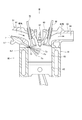
- FIG. 1 is a cross-sectional view showing a fuel injection valve according to the first embodiment.
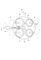
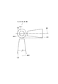
- FIG. 2 is a diagram showing a state in which the fuel injection valve according to the first embodiment is applied to an internal combustion engine.
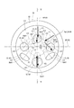
- FIG. 3 is a view of FIG. 2 from the direction of arrow III.
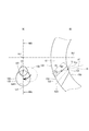
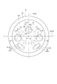
- FIG. 4 is a view of FIG. 1 from the direction of arrow IV.
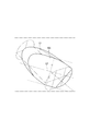
- FIG. 5 is a sectional view taken along line VV of FIG.
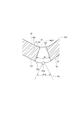
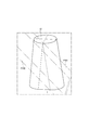
- FIG. 6 is a cross-sectional view showing the injection hole of the fuel injection valve according to the first embodiment and its vicinity.
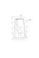
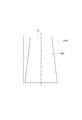
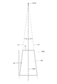
- FIG. 7 is a diagram for explaining how to define the inner wall intersection, the distance from the outlet opening to the inner wall intersection, and the injection hole length with respect to the injection hole of the fuel injection valve according to the first embodiment.
- FIG. 8 is a diagram for explaining how to define the inner wall intersection, the distance from the outlet opening to the inner wall intersection, and the injection hole length with respect to the injection hole of the fuel injection valve according to the first embodiment.
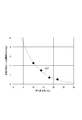
- FIG. 9 is a diagram showing the relationship between the atomization index and the position of the inner wall intersection with respect to the injection hole of the fuel injection valve according to the first embodiment.
- FIG. 10 is a cross-sectional view showing the injection hole of the fuel injection valve according to the second embodiment and its vicinity.
- FIG. 11 is a cross-sectional view showing the injection hole of the fuel injection valve according to the third embodiment and its vicinity.
- FIG. 12 is a cross-sectional view showing the injection hole of the fuel injection valve according to the fourth embodiment and its vicinity.
- FIG. 13 is a diagram showing the injection hole of the fuel injection valve according to the fifth embodiment and its vicinity.
- FIG. 14 is a diagram showing the injection hole of the fuel injection valve according to the sixth embodiment and its vicinity.
- FIG. 15 is a cross-sectional view including a perfect circular injection hole of the fuel injection valve according to the sixth embodiment.
- FIG. 16 is a schematic view showing a perfect circular injection hole of the fuel injection valve according to the sixth embodiment.
- FIG. 17 is a schematic view showing a non-circular injection hole of the fuel injection valve according to the sixth embodiment.
- FIG. 18 is a schematic view showing a non-circular injection hole of the fuel injection valve according to the sixth embodiment.
- FIG. 19 is a diagram showing a non-circular injection hole during fuel injection of the fuel injection valve according to the sixth embodiment.
- FIG. 20 is a cross-sectional view including a non-circular injection hole of the fuel injection valve according to the sixth embodiment.
- FIG. 21 is a cross-sectional view including a non-circular injection hole of the fuel injection valve according to the sixth embodiment.
- FIG. 22 is a diagram for explaining a virtual non-true cone of the fuel injection valve according to the sixth embodiment.
- FIG. 23 shows the relationship between the “injection hole opening angle” of the non-circular injection hole of the fuel injection valve according to the sixth embodiment and the “fuel spray opening angle that increases due to the shape of the non-round injection hole”. It is a diagram showing FIG. 24 is a diagram for explaining how to define the injection hole shaft of the non-circular injection hole of the fuel injection valve according to the sixth embodiment.
- FIG. 25 is a diagram for explaining how to define the injection hole shaft of the non-circular injection hole of the fuel injection valve according to the sixth embodiment.
- FIG. 26 is a diagram for explaining how to define the injection hole shaft of the non-circular injection hole of the fuel injection valve according to the sixth embodiment.
- FIG. 24 is a diagram for explaining how to define the injection hole shaft of the non-circular injection hole of the fuel injection valve according to the sixth embodiment.
- FIG. 25 is a diagram for explaining how to define the injection hole shaft of the non-circular injection hole of the fuel injection valve according to the sixth embodiment.
- FIG. 26 is a diagram for explaining
- FIG. 27 is a diagram for explaining how to define the injection hole shaft of the non-circular injection hole of the fuel injection valve according to the sixth embodiment.
- FIG. 28 is a diagram for explaining how to define the injection hole shaft of the non-circular injection hole of the fuel injection valve according to the sixth embodiment.
- FIG. 29 is a diagram for explaining how to define the injection hole shaft of the non-circular injection hole of the fuel injection valve according to the sixth embodiment.
- FIG. 30 is a diagram showing the relationship between the “injection hole opening angle” and the “spray opening angle” of the fuel injection valve according to the sixth embodiment.
- FIG. 31 is a diagram showing a non-circular injection hole at the end of fuel injection of the fuel injection valve according to the sixth embodiment.
- FIG. 32 is a cross-sectional view showing a non-circular injection hole at the end of fuel injection of the fuel injection valve according to the sixth embodiment.
- FIG. 33 is a schematic view showing a non-circular injection hole of the fuel injection valve according to the seventh embodiment.
- FIG. 34 is a schematic view showing a non-circular injection hole of the fuel injection valve according to the seventh embodiment.
- FIG. 35 is a diagram for explaining how to define the injection hole shaft of the non-circular injection hole of the fuel injection valve according to the seventh embodiment.
- FIG. 36 is a diagram for explaining how to define the injection hole shaft of the non-circular injection hole of the fuel injection valve according to the seventh embodiment.
- FIG. 37 is a diagram for explaining how to define the injection hole shaft of the non-circular injection hole of the fuel injection valve according to the seventh embodiment.
- FIG. 38 is a diagram for explaining how to define the injection hole shaft of the non-circular injection hole of the fuel injection valve according to the seventh embodiment.
- FIG. 39 is a diagram for explaining how to define the injection hole shaft of the non-circular injection hole of the fuel injection valve according to the seventh embodiment.
- FIG. 40 is a diagram for explaining how to define the injection hole shaft of the non-circular injection hole of the fuel injection valve according to the seventh embodiment.
- FIG. 41 is a diagram showing the relationship between the “injection hole opening angle” and the “spray opening angle” of the fuel injection valve according to the seventh embodiment.
- FIG. 42 is a diagram showing the nozzle bottom and the injection hole of the fuel injection valve according to the eighth embodiment.
- FIG. 43 is a diagram showing an injection hole of the fuel injection valve according to the ninth embodiment and its vicinity.
- the fuel injection valve according to the first embodiment is shown in FIG.
- the fuel injection valve 1 is applied to, for example, a gasoline engine (hereinafter, simply referred to as “engine”) 80 as an internal combustion engine, and injects gasoline as fuel to supply the engine 80 (see FIG. 2).
- engine 80 a gasoline engine (hereinafter, simply referred to as “engine”) 80 as an internal combustion engine, and injects gasoline as fuel to supply the engine 80 (see FIG. 2).
- the engine 80 includes a cylindrical cylinder block 81, a piston 82, a cylinder head 90, an intake valve 95, an exhaust valve 96, and the like.
- the piston 82 is provided so as to be reciprocally movable inside the cylinder block 81.
- the cylinder head 90 is provided so as to close the open end of the cylinder block 81.
- a combustion chamber 83 is formed between the inner wall of the cylinder block 81, the wall surface of the cylinder head 90, and the piston 82. The volume of the combustion chamber 83 increases or decreases as the piston 82 reciprocates.
- the cylinder head 90 has an intake manifold 91 and an exhaust manifold 93.
- An intake passage 92 is formed in the intake manifold 91.
- One end of the intake passage 92 is open to the atmosphere, and the other end is connected to the combustion chamber 83.
- the intake passage 92 guides the air sucked from the atmosphere side (hereinafter, referred to as “intake”) to the combustion chamber 83.
- An exhaust passage 94 is formed in the exhaust manifold 93. One end of the exhaust passage 94 is connected to the combustion chamber 83, and the other end is open to the atmosphere.
- the exhaust passage 94 guides the air containing the combustion gas generated in the combustion chamber 83 (hereinafter, referred to as “exhaust”) to the atmosphere side.
- the intake valve 95 is provided on the cylinder head 90 so that it can reciprocate by rotating a cam of a driven shaft that rotates in conjunction with a drive shaft (not shown).
- the intake valve 95 can be opened and closed between the combustion chamber 83 and the intake passage 92 by reciprocating.
- the exhaust valve 96 is provided on the cylinder head 90 so that it can reciprocate by rotating the cam.
- the exhaust valve 96 can be opened and closed between the combustion chamber 83 and the exhaust passage 94 by reciprocating.
- the fuel injection valve 1 is mounted on the cylinder block 81 side of the intake passage 92 of the intake manifold 91.
- the fuel injection valve 1 is provided so that the center line is inclined with respect to the center line of the combustion chamber 83 or has a twisting relationship.
- the center line of the combustion chamber 83 is the axis of the combustion chamber 83 and coincides with the axis of the cylinder block 81.
- the fuel injection valve 1 is provided on the side of the combustion chamber 83. That is, the fuel injection valve 1 is mounted on the side of the engine 80 and used.
- a spark plug 97 as an ignition device is provided between the intake valve 95 and the exhaust valve 96 of the cylinder head 90, that is, at a position corresponding to the center of the combustion chamber 83.
- the spark plug 97 is provided at a position where the fuel injected from the fuel injection valve 1 does not directly adhere, and at a position where the air-fuel mixture (combustible air) in which the fuel and the intake air are mixed can be ignited.
- the engine 80 is a direct injection type gasoline engine.
- the fuel injection valve 1 is provided so that a plurality of injection holes 13 are exposed on the radial outer portion of the combustion chamber 83.
- the fuel injection valve 1 is supplied with fuel pressurized to the fuel injection pressure by a fuel pump (not shown). Conical fuel spray Fo is injected into the combustion chamber 83 from the plurality of injection holes 13 of the fuel injection valve 1.
- two intake valves 95 and two exhaust valves 96 are provided in the engine 80.
- the two intake valves 95 are provided at the two branched ends of the intake manifold 91 on the cylinder block 81 side, respectively.
- the two exhaust valves 96 are provided at the two branched ends of the exhaust manifold 93 on the cylinder block 81 side, respectively.
- the fuel injection valve 1 is provided in the intake manifold 91 so that the center line is along the virtual plane VP100 that includes the shaft of the cylinder block 81 and passes between the two intake valves 95 and between the two exhaust valves 96.
- the fuel injection valve 1 includes a nozzle 10, a housing 20, a needle 30, a movable core 40, a fixed core 51, a spring 52 as a valve seat side urging member, a spring 53 as a fixed core side urging member, and a coil as a drive unit. It is equipped with 55 mag.
- the nozzle 10 is made of a metal such as martensitic stainless steel.
- the nozzle 10 is hardened so as to have a predetermined hardness. As shown in FIGS. 1, 4 and 5, the nozzle 10 has a nozzle cylinder portion 11, a nozzle bottom portion 12, a nozzle hole 13, a valve seat 14, and the like.
- the nozzle cylinder portion 11 is formed in a substantially cylindrical shape.
- the nozzle bottom portion 12 closes one end of the nozzle cylinder portion 11.
- the injection hole 13 is formed so as to connect the surface of the nozzle bottom 12 on the nozzle cylinder portion 11 side, that is, the inner wall, and the surface 122 on the side opposite to the nozzle cylinder portion 11 (see FIG. 5).
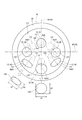
- a plurality of injection holes 13 are formed in the bottom portion 12 of the nozzle. In this embodiment, six injection holes 13 are formed (see FIG. 4).
- the valve seat 14 is formed in an annular shape around the injection hole 13 on the surface of the nozzle bottom 12 on the nozzle cylinder 11 side. The injection hole 13 will be described in detail later.
- the housing 20 has a first cylinder member 21, a second cylinder member 22, a third cylinder member 23, an inlet portion 24, and the like.
- the first cylinder member 21, the second cylinder member 22, and the third cylinder member 23 are all formed in a substantially cylindrical shape.
- the first cylinder member 21, the second cylinder member 22, and the third cylinder member 23 are arranged so as to be coaxial in the order of the first cylinder member 21, the second cylinder member 22, and the third cylinder member 23, and are connected to each other. ..
- the first cylinder member 21 and the third cylinder member 23 are formed of a magnetic material such as ferritic stainless steel and are subjected to a magnetic stabilization treatment.
- the second tubular member 22 is made of a non-magnetic material such as austenitic stainless steel.
- the second cylinder member 22 functions as a magnetic throttle portion.
- the first cylinder member 21 is provided so that the inner wall at the end opposite to the second cylinder member 22 fits into the outer wall of the nozzle cylinder portion 11 of the nozzle 10.
- the inlet portion 24 is formed in a tubular shape with a magnetic material such as ferritic stainless steel. The inlet portion 24 is provided so that one end is connected to the end portion of the third cylinder member 23 opposite to the second cylinder member 22.
- a fuel passage 100 is formed inside the housing 20.
- the fuel passage 100 is connected to the injection hole 13. That is, the nozzle cylinder portion 11 of the nozzle 10 forms a fuel passage 100 inside.
- a pipe (not shown) is connected to the inlet portion 24 on the opposite side of the third cylinder member 23. As a result, fuel from the fuel supply source (fuel pump) flows into the fuel passage 100 via the pipe.
- the fuel passage 100 guides fuel to the injection hole 13.
- a filter 25 is provided inside the inlet portion 24.
- the filter 25 collects foreign matter in the fuel flowing into the fuel passage 100.
- the needle 30 is formed in a rod shape by, for example, a metal such as martensitic stainless steel.
- the needle 30 is hardened so as to have a predetermined hardness.
- the needle 30 is housed in the housing 20 so that it can reciprocate in the fuel passage 100 in the axial direction of the housing 20.
- the needle 30 has a needle body 301, a seat portion 31, a large diameter portion 32, a flange portion 34, and the like.
- the needle body 301 is formed in a rod shape.
- the seat portion 31 is formed at the end portion of the needle body 301 on the nozzle 10 side and can come into contact with the valve seat 14.
- the large diameter portion 32 is formed in the vicinity of the seat portion 31 at the end of the needle body 301 on the valve seat 14 side.
- the outer diameter of the large diameter portion 32 is set to be larger than the outer diameter of the end portion of the needle body 301 on the valve seat 14 side.
- the large diameter portion 32 is formed so that the outer wall slides on the inner wall of the nozzle cylinder portion 11 of the nozzle 10. As a result, the needle 30 is guided to reciprocate in the axial direction at the end portion on the valve seat 14 side.
- the large-diameter portion 32 is formed with notches 33 so that a plurality of portions in the circumferential direction of the outer wall are notched. As a result, the fuel can flow between the notch 33 and the inner wall of the nozzle cylinder 11.
- the collar portion 34 is formed in a substantially cylindrical shape so as to extend radially outward from the end portion of the needle body 301 opposite to the seat portion 31.
- Axial hole portion 35 and radial hole portion 36 are formed in the needle body 301.
- the axial hole portion 35 is formed so as to extend in the axial direction from the end surface of the needle body 301 opposite to the seat portion 31.
- the radial hole portion 36 is formed so as to extend in the radial direction of the needle main body 301 to connect the axial hole portion 35 and the outer wall of the needle main body 301.
- the needle 30 opens and closes the injection hole 13 when the seat portion 31 separates from the valve seat 14 (separates) or comes into contact with the valve seat 14 (seating).
- the direction in which the needle 30 is separated from the valve seat 14 is referred to as a valve opening direction
- the direction in which the needle 30 abuts on the valve seat 14 is referred to as a valve closing direction.
- the movable core 40 is formed in a tubular shape with a magnetic material such as ferritic stainless steel.
- the movable core 40 is subjected to a magnetic stabilization process.
- the movable core 40 is provided inside the first cylinder member 21 and the second cylinder member 22 of the housing 20.
- the movable core 40 is formed in a substantially columnar shape.
- the movable core 40 is formed with a recess 41, a shaft hole 42, and a through hole 43.
- the recess 41 is formed so as to be recessed from the center of the end surface of the movable core 40 on the nozzle 10 side to the side opposite to the nozzle 10.
- the shaft hole 42 is formed so as to connect the end surface of the movable core 40 opposite to the nozzle 10 and the bottom surface of the recess 41 so as to pass through the shaft of the movable core 40.
- the through hole 43 is formed so as to connect the end surface of the movable core 40 on the nozzle 10 side and the end surface of the movable core 40 on the side opposite to the nozzle 10.
- a plurality of through holes 43 are formed at equal intervals in the circumferential direction of the movable core 40 on the radial outer side of the recess 41.
- the movable core 40 is provided inside the housing 20 with the needle body 301 inserted through the shaft hole 42. That is, the movable core 40 is provided on the outer side in the radial direction of the needle body 301. The movable core 40 can move relative to the needle body 301 in the axial direction. The inner wall forming the shaft hole 42 of the movable core 40 is slidable with the outer wall of the needle body 301.
- the portion of the end face on the opposite side of the nozzle 10 around the shaft hole 42 can be in contact with the end face on the nozzle 10 side of the collar portion 34 or separated from the end face on the nozzle 10 side of the collar portion 34. Is.
- the fixed core 51 is formed in a substantially cylindrical shape with a magnetic material such as ferritic stainless steel.
- the fixed core 51 is magnetically stabilized.
- the fixed core 51 is provided on the side of the movable core 40 opposite to the nozzle 10.
- the fixed core 51 is provided inside the housing 20 so that the outer wall is connected to the inner walls of the second cylinder member 22 and the third cylinder member 23.
- the end face of the fixed core 51 on the nozzle 10 side can come into contact with the end face of the movable core 40 on the fixed core 51 side.
- a cylindrical adjusting pipe 54 is press-fitted inside the fixed core 51.
- the spring 52 is, for example, a coil spring, and is provided between the adjusting pipe 54 and the needle 30 inside the fixed core 51.
- One end of the spring 52 is in contact with the adjusting pipe 54.
- the other end of the spring 52 is in contact with the end faces of the needle body 301 and the flange 34 on the opposite side of the nozzle 10.
- the spring 52 can urge the movable core 40 together with the needle 30 toward the nozzle 10 side, that is, in the valve closing direction. The urging force of the spring 52 is adjusted by the position of the adjusting pipe 54 with respect to the fixed core 51.
- the coil 55 is formed in a substantially cylindrical shape, and is provided so as to surround the radial outside of the second cylinder member 22 and the third cylinder member 23 of the housing 20 in particular. Further, a tubular holder 26 is provided on the outer side of the coil 55 in the radial direction so as to cover the coil 55.
- the holder 26 is made of a magnetic material such as ferritic stainless steel. In the holder 26, the inner wall at one end is connected to the outer wall of the first cylinder member 21, and the inner wall at the other end is magnetically connected to the outer wall of the third cylinder member 23.
- the coil 55 generates a magnetic force when electric power is supplied (energized).
- a magnetic force is generated in the coil 55, a magnetic circuit is formed in the movable core 40, the first cylinder member 21, the holder 26, the third cylinder member 23, and the fixed core 51, avoiding the second cylinder member 22 as the magnetic throttle portion.
- a magnetic attraction force is generated between the fixed core 51 and the movable core 40, and the movable core 40 is attracted to the fixed core 51 side together with the needle 30.
- the needle 30 moves in the valve opening direction, the seat portion 31 is separated from the valve seat 14, and the valve is opened.
- the injection hole 13 is opened, and fuel is injected from the injection hole 13.
- the movable core 40 can be attracted to the fixed core 51 side and the needle 30 can be moved to the side opposite to the valve seat 14, that is, in the valve opening direction.
- the movable core 40 is attracted to the fixed core 51 side (valve opening direction) by the magnetic attraction force, the end face on the fixed core 51 side collides with the end face on the movable core 40 side of the fixed core 51. As a result, the movable core 40 is restricted from moving in the valve opening direction.
- the spring 53 is, for example, a coil spring, and is provided in a state where one end is in contact with the bottom surface of the recess 41 of the movable core 40 and the other end is in contact with the stepped surface of the inner wall of the first cylinder member 21 of the housing 20. ..
- the spring 53 can urge the movable core 40 toward the fixed core 51, that is, in the valve opening direction.
- the urging force of the spring 53 is smaller than the urging force of the spring 52. Therefore, when the coil 55 is not energized, the seat portion 31 of the needle 30 is pressed against the valve seat 14 by the spring 52, and the movable core 40 is pressed against the collar portion 34 by the spring 53.
- the radial outer side of the third cylinder member 23 is molded by a mold portion 56 made of resin.
- the connector portion 57 is formed so as to project radially outward from the mold portion 56.
- a terminal 571 for supplying electric power to the coil 55 is insert-molded in the connector portion 57.
- the fuel flowing in from the inlet portion 24 is the inside of the filter 25, the fixed core 51 and the adjusting pipe 54, the axial hole portion 35, the radial hole portion 36, between the needle 30 and the inner wall of the housing 20, the needle 30 and the nozzle. It flows between the inner wall of the tubular portion 11, that is, the fuel passage 100, and is guided to the injection hole 13.
- the periphery of the movable core 40 and the needle 30 is filled with fuel. Further, when the fuel injection valve 1 is operated, fuel flows through the through hole 43 of the movable core 40, the axial hole portion 35 of the needle 30, and the radial hole portion 36. Therefore, the movable core 40 and the needle 30 can smoothly reciprocate in the axial direction inside the housing 20.
- the fuel pressure in the fuel passage 100 assumed when the fuel injection valve 1 of the present embodiment is used is, for example, 1 MPa or more. This embodiment is more advantageous as the pressure of the fuel in the fuel passage 100 becomes as high as 30 MPa or 100 MPa.
- the minimum value of the flow path area between the valve seat 14 and the needle 30 when the needle 30 is most separated from the valve seat 14 is the seat throttle area As, and the minimum value of the flow path area of the injection hole 13 is set.
- the nozzle aperture area is Ah, As> Ah.
- the seat drawing area As is a state in which the seat portion 31 of the needle 30 is most distant from the valve seat 14, that is, the end surface of the movable core 40 on the fixed core 51 side is in contact with the fixed core 51 and the flange portion 34.
- the injection hole throttle area Ah corresponds to the minimum value of the total area of the flow paths of all the six injection holes 13. That is, the injection hole throttle area Ah is the total area of the minimum values of the flow path areas perpendicular to the injection hole axis Axh1 of each injection hole 13.
- the injection hole 13 of the present embodiment will be described in detail.
- the needle 30 is not shown.
- the nozzle 10 has a sack wall surface 150, an inlet opening 131, an outlet opening 132, an inner wall of the injection hole 133, an injection hole 13, and a valve seat 14.
- the sack wall surface 150 is recessed from the center of the surface 121 on the nozzle cylinder 11 side of the nozzle bottom 12 to the side opposite to the nozzle cylinder 11, and forms a sack chamber 15 inside.
- the sack chamber 15 is formed between the sack wall surface 150 and the seat portion 31 of the needle 30.
- the valve seat 14 is formed in an annular shape around the sack wall surface 150 of the surface 121.
- the valve seat 14 is formed in a tapered shape so as to approach the axis Ax1 of the nozzle cylinder portion 11 from the nozzle cylinder portion 11 side toward the sack wall surface 150 side.
- the injection hole 13 connects the sack wall surface 150 and the surface 122 of the nozzle bottom 12 opposite to the nozzle cylinder portion 11 to inject fuel in the fuel passage 100.
- the sack wall surface 150 is formed in a curved surface shape.
- the injection hole 13 is the inlet opening 131 formed on the sack wall surface 150, which is the surface of the nozzle bottom 12 on the nozzle cylinder 11 side, and the nozzle bottom 12 on the opposite side of the nozzle cylinder 11. It has an outlet opening 132 formed on the surface 122, and a nozzle inner wall 133 connecting the inlet opening 131 and the outlet opening 132.
- the inlet opening 131 means a closed area as a virtual surface formed along the sack wall surface 150 by making a hole (injection hole 13) in the nozzle bottom portion 12, and the area of this area. Is the area of the entrance opening 131.
- the outlet opening 132 is closed as a virtual surface formed along the surface 122 of the nozzle bottom 12 opposite to the nozzle cylinder portion 11 by making a hole (injection hole 13) in the nozzle bottom 12. The area of this area is defined as the area of the outlet opening 132. In each of the six injection holes 13, the area of the outlet opening 132 is larger than the area of the inlet opening 131.
- the six injection holes 13 are formed in a taper shape so that the injection hole inner wall 133 is separated from the injection hole shaft Axh1, which is the axis of the injection hole 13, as the injection hole inner wall 133 moves from the inlet opening 131 side to the outlet opening 132 side. ing.
- the six injection holes 13 correspond to "tapered injection holes”.
- each of the six injection holes 13 is referred to as injection holes 61, 62, 63, 64, 65, 66.
- the centers of the inlet openings 131 of the injection holes 61, 62, 63, 64, 65, 66 are arranged at equal intervals on the pitch circle Cp1 centered on the axis Ax1.
- the injection holes 61 and 64 are formed on the virtual plane VP101 including the shaft Ax1 of the nozzle cylinder portion 11 so that the shaft Ax1 of the nozzle cylinder portion 11 is located between them. That is, the virtual plane VP101 passes through the injection holes 61 and 64. Further, the injection holes 61 and 64 are formed so that the respective injection hole axes Axh1 are included in the virtual plane VP101. In the nozzle holes 61 and 64, the nozzle shaft Axh1 intersects the shaft Ax1 of the nozzle cylinder portion 11, and the nozzle shaft Axh1 is not twisted with respect to the shaft Ax1 (see FIG. 4).
- the inlet openings 131 of the injection holes 62 and 66 are formed on the injection hole 61 side with respect to the virtual plane VP102 including the axis Ax1 of the nozzle cylinder portion 11 and perpendicular to the virtual plane VP101.
- the inlet openings 131 of the injection holes 63 and 65 are formed on the injection hole 64 side with respect to the virtual plane VP102.
- the nozzle shaft Axh1 does not intersect the shaft Ax1 of the nozzle cylinder portion 11, and the nozzle shaft Axh1 has a twisting relationship with respect to the shaft Ax1 (see FIG. 4). ..
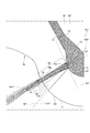
- the normal Ln1 of the sack wall surface 150 at the opening intersection Po1 which is the intersection of the injection hole axis Axh1 and the inlet opening 131 is the injection hole inner wall 133 or the injection hole inner wall 133.
- the distance from the outlet opening 132 to the inner wall intersection Pw1 which is the intersection of the normal Ln1 and the injection hole inner wall 133 or the virtual inner wall VW1 is determined. If the injection hole length, which is the length between the inlet opening 131 and the outlet opening 132 of the injection hole inner wall 133 on the side where the LA and the inner wall intersection Pw1 is formed, is LB, the injection hole 13 is LA / LB>. It is formed to be -0.2. More specifically, the injection hole 13 is formed so that 1> LA / LB> ⁇ 0.2.
- LA when the normal line Ln1 intersects the injection hole inner wall 133 (see FIG. 6), LA takes a positive value. Therefore, LA / LB is a positive value. On the other hand, when the normal Ln1 intersects the virtual inner wall VW1, LA takes a negative value. Therefore, LA / LB has a negative value.
- the normal Ln1 intersects with the injection hole inner wall 133 on the shaft Ax1 side of the nozzle cylinder portion 11 among the two injection hole inner walls 133 shown in the cross section by the virtual surface Sc1.
- the direction of the normal line Ln1 is determined by the shape of the sack wall surface 150 on which the entrance opening 131 is formed.
- a gasoline engine having a spark plug needs to be provided with a jet hole toward the ignition source and a jet hole for forming a uniform spray in the cylinder even if it is mounted on the side as well as on the center.
- the injection direction rarely coincides with the radial direction of the valve shaft (axis Ax1), and at least one of the injection holes has a twist.
- the projection angle ⁇ p1 between the extension line Le1 connecting the axis Ax1 of the nozzle cylinder portion 11 and the center of the inlet opening 131 and the injection hole axis Axh1 is 0 °.
- the normal line Ln1 and the injection are performed.
- the intersection with the hole inner wall 133 is the inner wall intersection Pw1
- the distance from the outlet opening 132 to the inner wall intersection Pw1 is LA
- the length between is defined as the injection hole length LB.
- the sheet drawing area As is larger than the injection hole drawing area Ah. Therefore, when the seat portion 31 of the needle 30 is separated from the valve seat 14, the fuel flows into the sack chamber 15 in a state where there is almost no throttle by the seat portion 31 and the pressure loss is small. As a result, the pressure vector acts in the normal Ln1 direction. Therefore, the fuel is injected in the normal Ln1 direction. Further, in the present embodiment, the normal line Ln1 and the injection hole inner wall 133 intersect. Therefore, a liquid film of fuel is formed in the injection hole 13.
- FIG. 6 shows the state in the sack chamber 15 and the injection hole 13 when the seat portion 31 of the needle 30 is most separated from the valve seat 14.
- hatching of the cross section of the member is omitted in order to avoid complicating the drawing.
- the darker the shaded area the higher the pressure.
- the pressure of the sack chamber 15 is high, and the pressure of the portion of the injection hole 13 on the inlet opening 131 side from the inner wall intersection Pw1 which is the intersection of the normal Ln1 and the injection hole inner wall 133 is high. I understand.
- the fuel flow generated at the inlet opening 131 can collide with the injection hole inner wall 133, and the pressure in the sack chamber 15 can be efficiently converted into energy for forming a liquid film, and the fuel can be atomized. Is possible.
- the effect of the fuel injection valve 1 of the present embodiment is shown by the atomization index based on the Fraser model.
- the volume average particle size D 30 after splitting of the fuel is calculated by the following equation 1.
- D 30 3.78 (2 / E) 1/3 (hr / V 2 ) 1/3 ( ⁇ 2 / ⁇ L ⁇ a ) 1/6 ... Equation 1
- Equation 1 E, h, r, V, ⁇ , ⁇ L , and ⁇ a are experimental constants, liquid film thickness, distance, liquid film velocity, surface tension, fuel density, and air density, respectively.
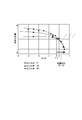
- the projection angle ⁇ p1 that is, the injection hole 13 whose twist angle (see FIG. 4) is 0 °, 30 °, and 60 °.
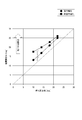
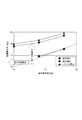
- the relationship between the atomization index and LA / LB is as shown in FIG.
- FIG. 9 shows the values obtained by analysis. It should be noted that what is obtained in the analysis is the liquid film thickness and the liquid film velocity.
- the atomization index is a value based on the liquid film velocity (spray rate) and the liquid film thickness, and the smaller the atomization index, the finer the fuel spray is.
- the injection hole 13 is formed so that LA / LB> -0.2. Therefore, the fuel spray injected from the injection hole 13 can be effectively atomized.
- the fuel in the sack chamber 15 is not easily affected by the inflow from the valve seat 14 side, a flow velocity is generated in the normal Ln1 direction at the inlet opening 131, and the nozzle cylinder Even in the injection hole 13 in which the injection hole axis Axh1 has a twisting relationship with respect to the axis Ax1 of the portion 11, it depends on the kinetic energy when colliding with the injection hole inner wall 133, so that the atomization index (movement in the X, Y, Z directions) It depends on energy) and can be organized.
- the minimum value of the flow path area between the valve seat 14 and the needle 30 when the needle 30 is most separated from the valve seat 14 is the seat throttle area As and the flow of the injection hole 13.
- the minimum value of the road area is the injection hole throttle area Ah, As> Ah.
- the normal Ln1 of the sack wall surface 150 at the opening intersection Po1 which is the intersection of the injection hole shaft Axh1 and the inlet opening 131 has the injection hole inner wall 133 or the injection hole inner wall 133 with the nozzle cylinder portion 11. It is formed so as to intersect the virtual inner wall VW1 extending to the opposite side.
- the distance from the outlet opening 132 to the inner wall intersection Pw1 which is the intersection of the normal Ln1 and the injection hole inner wall 133 or the virtual inner wall VW1 in the cross section by the virtual surface Sc1 including the injection hole axis Axh1 is LA.
- the injection hole length which is the length between the inlet opening 131 and the outlet opening 132 of the injection hole inner wall 133 on the side where the inner wall intersection Pw1 is formed, is LB
- the injection hole 13 is LA / LB>-. It is formed to be 0.2. Therefore, the high-pressure fuel can be effectively collided with the injection hole inner wall 133, and the liquid film can be effectively formed in the injection hole 13. Therefore, the fuel spray Fo injected from the injection hole 13 can be atomized more effectively.
- the normal line Ln1 intersects with the injection hole inner wall 133 on the axis Ax1 side of the nozzle cylinder portion 11 among the two injection hole inner walls 133 shown in the cross section by the virtual surface Sc1. Even with such a configuration, the liquid film is effectively formed in the injection hole 13 by the high-pressure fuel colliding with the injection hole inner wall 133. Therefore, the pressure energy of the fuel can be utilized to effectively atomize the fuel spray Fo injected from the injection hole 13.
- FIG. 10 A part of the fuel injection valve according to the second embodiment is shown in FIG.
- the configuration of the nozzle 10 is different from that in the first embodiment.
- the shape of the sack wall surface 150 on which the entrance opening 131 is formed is different from that of the first embodiment. Therefore, the normal line Ln1 intersects the injection hole inner wall 133 on the valve seat 14 side, that is, the side opposite to the axis Ax1 of the nozzle cylinder portion 11 among the two injection hole inner walls 133 shown in the cross section by the virtual surface Sc1 (FIG. 10). Even with such a configuration, the liquid film is effectively formed in the injection hole 13 by the high-pressure fuel colliding with the injection hole inner wall 133. Therefore, the pressure energy of the fuel can be utilized to effectively atomize the fuel spray Fo injected from the injection hole 13.
- the second embodiment has the same configuration as the first embodiment except for the above points.
- FIG. 10 A part of the fuel injection valve according to the third embodiment is shown in FIG.
- the configuration of the nozzle 10 is different from that in the first embodiment.
- the curvature of the sack wall surface 150 in the cross section including the axis Ax1 of the nozzle cylinder portion 11 is different from that in the first embodiment. Therefore, in the present embodiment, the position of the inner wall intersection Pw1 which is the intersection of the normal line Ln1 and the injection hole inner wall 133 is different from that of the first embodiment.
- the normal line Ln1 intersects the nozzle inner wall 133 on the axis Ax1 side of the nozzle cylinder portion 11 among the two nozzle inner walls 133 shown in the cross section by the virtual surface Sc1. .. Even with such a configuration, the liquid film is effectively formed in the injection hole 13 by the high-pressure fuel colliding with the injection hole inner wall 133. Therefore, the pressure energy of the fuel can be utilized to effectively atomize the fuel spray Fo injected from the injection hole 13.
- the third embodiment has the same configuration as the first embodiment except for the above-mentioned points.
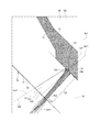
- FIG. 10 A part of the fuel injection valve according to the fourth embodiment is shown in FIG.
- the configuration of the nozzle 10 is different from that in the first embodiment.
- the sack wall surface 150 is formed in a tapered shape so as to approach the axis Ax1 of the nozzle cylinder portion 11 from the nozzle cylinder portion 11 side toward the nozzle bottom portion 12 side.
- the entrance opening 131 is formed on the tapered sack wall surface 150.
- the normal line Ln1 intersects with the injection hole inner wall 133 on the axis Ax1 side of the nozzle cylinder portion 11 among the two injection hole inner walls 133 shown in the cross section by the virtual surface Sc1.
- the fourth embodiment has the same configuration as the first embodiment except for the above points.
- the center of the inlet opening 131 of the injection holes 61, 62, 64, 66 is arranged on the pitch circle Cp1 centered on the axis Ax1.
- the center of the inlet opening 131 of the injection holes 63 and 65 is arranged outside the pitch circle Cp1.
- FIGS. 14 and 15 A part of the fuel injection valve according to the sixth embodiment is shown in FIGS. 14 and 15.
- the configuration of the injection hole 13 and the like are different from those in the first embodiment.
- the pressure of the fuel in the fuel passage 100 assumed when the fuel injection valve 1 of the present embodiment is used is, for example, about 20 MPa.
- the injection hole 13 of the present embodiment will be described in detail.
- the needle 30 is not shown.
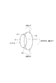
- the angle formed by the two injection hole inner walls 133 of the injection hole 13 of 1 is referred to as the “injection hole opening angle”.
- the angle formed by the two contours of the fuel spray Fo injected from the injection hole 13 of 1 is referred to as the “fuel spray opening angle”.
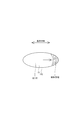
- the injection holes 63 and 65 have an elliptical shape, that is, a non-perfect circular shape when viewed from the injection hole axis Axh1 direction (see FIG. 14).
- the injection holes 63 and 65 are referred to as "non-round injection holes”.
- the injection holes 63 and 65 are appropriately referred to as "oval injection holes” or "elliptical injection holes”.
- the "oval injection hole” is an injection hole in which the shape of the outlet opening 132 is non-round and has an oval shape such as an egg shape, an ellipse, or a track shape.
- An ellipse is a circle with a constant sum of distances from two focal points.
- the shape of the outlet openings 132 of the injection holes 63 and 65 is an ellipse having two focal points.
- the outlet opening 132 includes an injection hole 13 having an egg-shaped, elliptical or track shape.
- the "non-round injection hole” shall include an "oval injection hole", an "elliptical injection hole”, and a "track injection hole”.
- the "longest diameter” means the longest width among the widths of the shape, and the shape of the outlet opening 132 of the injection holes 63 and 65 corresponds to the length of the long axis.
- the "shortest diameter” means the shortest width among the widths of the shape, and the shape of the outlet openings 132 of the injection holes 63 and 65 corresponds to the length of the minor axis.
- the ratio of the longest diameter a2 of the outlet opening 132 to the shortest diameter b2 is 1. Therefore, in the injection holes 61, 62, 64, 66, the shape of the outlet opening 132 is a perfect circle when viewed from the injection hole axis Axh1 direction (see FIG. 14).
- the injection holes 61, 62, 64, 66 are referred to as "round injection holes”.
- one or more (two) of the plurality of injection holes 13 has a injection hole 13 in which the ratio of the longest diameter to the shortest diameter of the outlet opening 132 is larger than 1. It is a non-round injection hole.
- the shapes of the inlet opening 131 and the outlet opening 132 are perfectly circular. Further, the inlet opening 131 and the outlet opening 132 are formed coaxially. Therefore, in the cross section formed by the first virtual plane VP1 which is a virtual plane including the injection hole axis Axh1, the angle ⁇ formed by the injection hole inner wall 133 is constant in the circumferential direction of the outlet opening 132.
- the injection holes 63 and 65 as non-circular injection holes have an elliptical shape of the inlet opening 131 and the outlet opening 132. Further, the inlet opening 131 and the outlet opening 132 are formed coaxially so that the directions of the major axis and the minor axis coincide with each other. Therefore, in the cross section by the second virtual plane VP2 which is a virtual plane including the injection hole axis Axh1, the angle at which the angle formed by the injection hole inner wall 133 is maximized is ⁇ 1, and the third virtual plane which is the virtual plane including the injection hole axis Axh1. In the cross section by VP3, assuming that the angle formed by the inner wall of the injection hole 133 is ⁇ 2, the second virtual plane VP2 and the third virtual plane VP3 are orthogonal to each other.
- the non-round injection hole has an elliptical shape in which the inlet opening 131 and the outlet opening 132 have the same flatness.
- the "major axis” means the longest width among the widths of the shape, and corresponds to the "major axis” in the ellipse.
- the “minor axis” means the shortest width of the shape and corresponds to the "minor axis” in the ellipse.
- the injection holes 63 and 65 as the non-circular injection holes are formed so that the minor axis direction of the outlet opening 132 is along the injection direction of the fuel injected from the non-round injection hole. There is.
- the minor axis direction and the injection direction coincide with each other, the minor axis is on a virtual plane passing through the injection hole axis Axh1 and parallel to the axis Ax1.
- the "minor axis direction” corresponds to the minor axis of the outlet opening 132, that is, the direction along the minor axis when viewed from the axis Ax1 direction of the nozzle cylinder portion 11.
- the "fuel injection direction” corresponds to the direction along the injection hole axis Axh1 when viewed from the axis Ax1 direction of the nozzle cylinder portion 11.
- the "major axis direction” corresponds to the major axis of the outlet opening 132, that is, the direction along the major axis.
- the injection hole opening angle of the perfect circular injection hole (64), which is the injection hole 13 in which the ratio of the longest diameter to the shortest diameter of the outlet opening 132 among the plurality of injection holes 13 is 1, is ⁇ ( deg)
- the opening angle of the fuel spray Fo injected from the perfect circular injection hole is ⁇ f (deg)
- the average pressure of the fuel in the fuel passage 100 when the fuel is injected from the perfect circular injection hole is P (MPa).
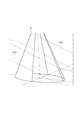
- the virtual cone is defined as a virtual true cone Vc1 (see FIG. 15).
- " ⁇ " represents a power.
- P 20 (MPa)
- 0.5 ⁇ P ⁇ 0.6 is about 3.0.
- the maximum injection hole opening angle of the non-round injection hole (63) is ⁇ 1 (deg)
- the minimum injection hole opening angle is ⁇ 2 (deg)
- the injection is performed from the non-round injection hole.
- the maximum opening angle of the fuel spray Fo is ⁇ f1 (deg)
- the minimum opening angle of the fuel spray Fo injected from the non-circular injection hole is ⁇ f2 (deg).
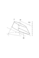
- the intersection of the injection hole axis Axh1 of the non-circular injection hole and the outlet opening 132 is defined as the apex Pv2, and the angle formed by the two generatrix in the cross section by the second virtual plane VP2 including the injection hole axis Axh1 of the non-round injection hole
- ⁇ f2 ⁇ 2 + 0.5 ⁇ P ⁇ 0.
- the virtual cone is defined as the virtual non-true cone Vc2 (see FIGS. 20, 21, 22)
- at least two adjacent injection holes 13 among the six injection holes 13 are the virtual true cone Vc1 or the virtual non-true cone.
- the cone Vc2 is formed so as not to interfere with the virtual true cone Vc1 or the virtual non-true cone Vc2.
- all of the six injection holes 13 are formed so that the virtual true cone Vc1 or the virtual non-true cone Vc2 does not interfere with the virtual true cone Vc1 or the virtual non-true cone Vc2. There is.
- FIG. 23 shows the “injection hole opening angle” ( ⁇ 1) when the “injection hole opening angle” ( ⁇ 1) is changed and the “increased fuel spray opening due to the shape of the non-circular injection hole”.
- This is an experimental result showing the relationship with "angle" (non-round injection hole + ⁇ spray opening angle).
- the larger the “injection hole opening angle” ( ⁇ 1) the smaller the “fuel spray opening angle that increases due to the shape of the non-circular injection hole”.
- LCs1 corresponds to "17 x e ⁇ (-0.13 x ⁇ 1)" in the above formula 3.
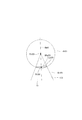
- a sphere B101 centered on the apex Pv101 set in step 3 is created, and a surface formed inside the intersection line Lx101 between the sphere B101 and the virtual cone Vc101 (inner wall 133 of the injection hole) is virtualized.
- the surface is VPx101.
- the straight line connecting the point Pt101 (see FIG. 29) that divides the straight line L101 passing through the portion having the longest width of the virtual surface VPx101 and the apex Pv101 is the injection hole axis Axh1.
- the opening angle (spray opening angle) of the fuel spray injected from the perfect circular injection hole is set to the "injection hole opening angle” and the "opening angle of the fuel spray increased by the fuel pressure in the fuel passage 100".
- the size is the sum of "0.5 x P ⁇ 0.6" corresponding to "”.
- For the opening angle (spray opening angle) of the fuel spray injected from the non-circular injection hole add “0.5 x P ⁇ 0.6" to the "injection hole opening angle” on the major axis side, and further , The size is the sum of "17 x e ⁇ (-0.13 x ⁇ 1)" corresponding to "the opening angle of the fuel spray increased due to the shape of the non-round injection hole”.
- the opening angle of the fuel spray injected from the non-circular injection hole is larger than the opening angle of the fuel spray injected from the perfect circular injection hole as compared with the major axis side.
- the non-circular injection hole Due to the widening of the spray angle of the non-circular injection hole, the length of the fuel spray injected from the non-round injection hole becomes shorter than the length of the fuel spray injected from the perfect circular injection hole. Therefore, it can be said that the non-circular injection hole has a higher effect of lowering the penetration of the fuel spray than the perfect circular injection hole.
- the injection holes 61, 62, 64, 66 as perfect circular injection holes and the injection holes 63, 65 as non-round injection holes are arranged as shown in FIG. 14, and all the injection holes 13 (Injection holes 61 to 66) are formed so that the virtual non-true cone Vc2 and the virtual true cone Vc1 or the virtual non-true cone Vc2 do not interfere with each other. Therefore, a closed space is not formed between the fuel sprays, no negative pressure is generated, and air can be introduced. As a result, it is possible to prevent the fuel sprays from contracting and coalescing. Therefore, it is possible to suppress the wetting in the cylinder and the deterioration of the spray characteristics due to the high penetration of the spray.
- the accumulation of the deposit on the inner wall 133 of the injection hole is suppressed, the penetration of the fuel spray is reduced, and the fuel sprays injected from the injection hole 13 do not interfere with each other.
- the injection hole 13 By forming the injection hole 13 and appropriately setting the injection hole opening angle, it is possible to suppress wetting in the cylinder and deterioration of the spray characteristics due to high penetration of the spray.
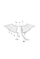
- the fuel in the non-round injection hole, during fuel injection, the fuel is extended in the major axis direction (major axis side) and the fuel is ejected in the form of a liquid film to promote division and spray the fuel. Can be atomized.
- the fuel in the injection hole collects in the R portion in the major axis direction (major axis side) and is ejected in the form of a liquid thread, resulting in poor fuel sharpness. , The wetness around the injection hole on the outer wall of the nozzle 10 may increase (see FIGS. 31 and 32).
- the flatness a1 / b1 (> 1) of the outlet opening 132 of the injection hole 63 as a non-circular injection hole is the outlet opening 132 of the injection hole 64 as a perfect circular injection hole.
- the area of the inlet opening 131 of the non-round injection hole (63, 65) having a large flatness of the outlet opening 132 is such that the perfect circular injection hole (61, 62, 64,) having a small flatness of the outlet opening 132. It is smaller than the area of the entrance opening 131 of 66).
- the area of the inlet opening 131 is small, so that it is difficult for fuel to flow, and the flatness of the outlet opening 132 is large. , 65), as well as air flowing into the sack chamber 15, fuel can easily flow from the large area of the inlet opening 131, and the flatness of the outlet opening 132 is small from the perfect circular injection holes (61, 62, 64, 66).
- the fuel is completely blown out and the injection is completed. Therefore, the amount of low-pressure fuel injected from the injection hole 13 having a large flatness, which is easy to get wet with fuel, can be reduced, and fuel wetting can be suppressed. Therefore, it is possible to suppress the tip wet to the same level as the conventional technique while achieving both a wide angle of the fuel spray and a minimization of the influence of the spray change.
- one or more of the plurality of injection holes 13 are non-true injection holes in which the ratio of the longest diameter to the shortest diameter of the outlet opening 132 is larger than 1.
- a virtual non-true cone Vc2 and a virtual true cone Vc1 are defined for the non-round injection hole and the perfect circular injection hole, respectively, and at least two adjacent injection holes 13 are defined as the virtual non-true cone Vc2 and the virtual true cone Vc1 or.
- the injection holes 63 and 65 as the non-circular injection holes are formed so that the minor axis direction of the outlet opening 132 is along the injection direction of the fuel injected from the non-round injection hole. There is. Therefore, the liquid film can be thinned and atomized by running the fuel along the inner wall 133 of the injection hole in the long axis direction.
- one or more non-round injection holes have an elliptical shape having the same flatness at the inlet opening 131 and the outlet opening 132. Therefore, when the injection hole 13 is laser-machined, the focal point can be fixed and the laser can be scanned, and a non-round injection hole can be easily formed.
- the sixth embodiment has the same configuration as the first embodiment except for the above points.
- the minimum value of the flow path area between the valve seat 14 and the needle 30 when the needle 30 is most separated from the valve seat 14 is set to the seat throttle area As and the injection hole 13.
- the minimum value of the flow path area is the injection hole throttle area Ah, As> Ah.
- the normal Ln1 of the sack wall surface 150 at the opening intersection Po1 which is the intersection of the injection hole shaft Axh1 and the inlet opening 131 has the nozzle inner wall 133 or the nozzle inner wall 133 as the nozzle cylinder portion 11. It is formed so as to intersect the virtual inner wall VW1 extending to the opposite side (see FIG. 15). Therefore, in addition to the above-mentioned effect, the same effect as that of the first embodiment can be obtained.
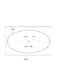
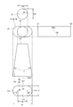
- the injection holes 63 and 65 as non-round injection holes have an inlet opening 131 having a perfect circular shape with a radius R1 and an outlet opening 132 having an inlet opening 131. It is a shape in which two semicircles Ch1 having the same curvature as the shape are connected by a straight line Lh1. Therefore, the injection holes 63 and 65 have a track shape, that is, a non-circular shape when viewed from the injection hole axis Axh1 direction (see FIG. 33).
- the injection holes 63 and 65 are referred to as "non-round injection holes”.
- the injection holes 63 and 65 are appropriately referred to as "track injection holes”.
- the radius R2 of the semicircle Ch1 is the same as the radius R1 of the inlet opening 131.
- the injection holes 63 and 65 as non-round injection holes have a ratio of the longest diameter a10 and the shortest diameter b10 of the inlet opening 131 and a flatness a10 / b10 of 1 (see FIG. 33).
- the injection holes 63 and 65 as non-round injection holes have a ratio of the longest diameter a1 and the shortest diameter b1 of the outlet opening 132 and the flatness a1 / b1 larger than 1 (see FIG. 33).
- the shortest diameter b10 of the inlet opening 131 and the shortest diameter b1 of the outlet opening 132 are the same.
- the distance X between the centers of the two semicircles Ch1 forming the outlet opening 132 is determined by the opening angles of the injection holes 63 and 65.
- the injection holes 63 and 65 as the non-circular injection holes are formed so that the minor axis direction of the outlet opening 132 is along the injection direction of the fuel injected from the non-round injection hole.
- the "minor diameter direction” corresponds to the minor diameter of the outlet opening 132, that is, the direction along the smallest width direction D1 of the width of the outlet opening 132 when viewed from the axis Ax1 direction of the nozzle cylinder portion 11.
- the "fuel injection direction” corresponds to the direction along the injection hole axis Axh1 when viewed from the axis Ax1 direction of the nozzle cylinder portion 11.
- the “major axis direction” corresponds to the major axis of the outlet opening 132, that is, the direction along the direction D2 having the largest width among the widths of the outlet opening 132.
- the virtual non-round cone Vc2 when the virtual non-round cone Vc2 is defined in the same manner as the non-round injection holes of the first embodiment, among the six injection holes 13, All the injection holes 13 are formed so that the virtual true cone Vc1 or the virtual non-true cone Vc2 does not interfere with the virtual true cone Vc1 or the virtual non-true cone Vc2.
- the opening angle (spray opening angle) of the fuel spray injected from the truck injection hole is larger than the opening angle of the fuel spray injected from the elliptical injection hole. Therefore, it can be seen that the truck injection hole is more effective in reducing the penetration of the fuel spray than the elliptical injection hole.
- the inlet opening 131 has a perfect circular shape
- the outlet opening 132 has the shape of the inlet opening 131. It has a shape in which two semicircles Ch1 having the same curvature are connected by a straight line Lh1. Therefore, the radius of curvature of the R portion at the outer edge of the outlet opening 132 can be increased as compared with the elliptical injection hole, and the fuel can easily escape from the R portion. As a result, wetting of the tip of the nozzle 10 can be suppressed.
- the seventh embodiment has the same configuration as the sixth embodiment except for the above-mentioned points.
- the nozzle 10 does not have the injection hole 64 shown in the first embodiment. That is, in the present embodiment, five injection holes 13 are formed in the nozzle 10.
- the centers of the inlet openings 131 of the injection holes 61, 62, 63, 65, and 66 are arranged at equal intervals on the pitch circle Cp1 centered on the axis Ax1.
- FIG. 9th Embodiment A part of the fuel injection valve according to the ninth embodiment is shown in FIG.
- the configuration of the injection hole 13 as a non-circular injection hole is different from that in the sixth embodiment.
- the injection hole 63 as a non-circular injection hole is formed so that both the inlet opening 131 and the outlet opening 132 have a rectangular shape.
- the ratio of the length a3 of the long side to the length b3 of the short side of the outlet opening 132 and the flatness a3 / b3 are larger than 1.
- the inlet opening 131 has a perfect circular shape and the outlet opening 132 has a track shape.
- the ratio of the major axis length a1 and the minor axis length b1 of the outlet opening 132 and the flatness a1 / b1 are larger than 1. That is, the injection hole 65 has the same configuration as the injection hole 65 in the seventh embodiment.
- the ninth embodiment has the same configuration as the sixth embodiment except for the above-mentioned points.
- the injection hole 13 is formed such that the normal Ln1 intersects the virtual inner wall VW1 which extends the injection hole inner wall 133 to the side opposite to the nozzle cylinder portion 11 instead of the injection hole inner wall 133.
- the injection hole 13 is formed so that LA / LB> ⁇ 0.2.
- the normal line Ln1 intersects with the injection hole inner wall 133 on the axis Ax1 side of the nozzle cylinder portion 11 among the two injection hole inner walls 133 shown in the cross section by the virtual surface Sc1.
- the normal Ln1 may intersect with the virtual inner wall VW1 on the axis Ax1 side of the nozzle cylinder portion 11 among the two virtual inner wall VW1s shown in the cross section by the virtual surface Sc1.
- the normal line Ln1 may intersect the virtual inner wall VW1 on the side opposite to the axis Ax1 of the nozzle cylinder portion 11 of the two virtual inner wall VW1s shown in the cross section by the virtual surface Sc1. Good.
- At least one of the plurality of injection holes 13 is formed in a taper shape so that the injection hole inner wall 133 is separated from the injection hole axis Axh1 as the injection hole inner wall 133 moves from the inlet opening 131 side to the outlet opening 132 side. Any taper injection hole may be used.
- At least one of at least one tapered injection hole may be formed so that the normal Ln1 of the sack wall surface 150 at the opening intersection Po1 intersects the injection hole inner wall 133 or the virtual inner wall VW1. ..
- the average pressure P (MPa) of the fuel in the fuel passage when the fuel is injected from the injection hole is 20 (MPa).
- P may be lower than 20 or higher than 20 as long as the plurality of injection holes are formed so as to satisfy the relationship of the above formulas 1 to 3. That is, the injection hole can be appropriately formed according to the pressure of the fuel in the fuel passage assumed when the fuel injection valve is used.
- the fuel injection valve may be mounted on the engine 80 in any posture.
- the nozzle cylinder portion and the nozzle bottom portion of the nozzle may be formed separately.
- the first cylinder member 21 of the housing 20 and the nozzle or the nozzle cylinder portion may be integrally formed.
- first cylinder member 21, the second cylinder member 22, and the third cylinder member 23 of the housing 20 may be integrally formed.
- the second cylinder member 22 may be formed thinly to form a magnetic drawing portion.
- a fuel injection valve is applied to a direct injection type gasoline engine.
- the fuel injection valve may be applied to, for example, a diesel engine, a port injection type gasoline engine, or the like.
- the present disclosure is not limited to the above-described embodiment, and can be implemented in various forms without departing from the gist thereof.
Landscapes
- Engineering & Computer Science (AREA)
- Chemical & Material Sciences (AREA)
- Combustion & Propulsion (AREA)
- Mechanical Engineering (AREA)
- General Engineering & Computer Science (AREA)
- Physics & Mathematics (AREA)
- Electromagnetism (AREA)
- Fuel-Injection Apparatus (AREA)
Priority Applications (3)
| Application Number | Priority Date | Filing Date | Title |
|---|---|---|---|
| DE112020002935.2T DE112020002935T5 (de) | 2019-06-20 | 2020-06-16 | Kraftstoffeinspritzventil |
| CN202080044553.0A CN114008317B (zh) | 2019-06-20 | 2020-06-16 | 燃料喷射阀 |
| US17/554,723 US12012916B2 (en) | 2019-06-20 | 2021-12-17 | Fuel injection valve |
Applications Claiming Priority (2)
| Application Number | Priority Date | Filing Date | Title |
|---|---|---|---|
| JP2019114737A JP7439399B2 (ja) | 2019-06-20 | 2019-06-20 | 燃料噴射弁 |
| JP2019-114737 | 2019-06-20 |
Related Child Applications (1)
| Application Number | Title | Priority Date | Filing Date |
|---|---|---|---|
| US17/554,723 Continuation US12012916B2 (en) | 2019-06-20 | 2021-12-17 | Fuel injection valve |
Publications (1)
| Publication Number | Publication Date |
|---|---|
| WO2020255943A1 true WO2020255943A1 (ja) | 2020-12-24 |
Family
ID=73993892
Family Applications (1)
| Application Number | Title | Priority Date | Filing Date |
|---|---|---|---|
| PCT/JP2020/023522 Ceased WO2020255943A1 (ja) | 2019-06-20 | 2020-06-16 | 燃料噴射弁 |
Country Status (5)
| Country | Link |
|---|---|
| US (1) | US12012916B2 (enExample) |
| JP (1) | JP7439399B2 (enExample) |
| CN (1) | CN114008317B (enExample) |
| DE (1) | DE112020002935T5 (enExample) |
| WO (1) | WO2020255943A1 (enExample) |
Families Citing this family (1)
| Publication number | Priority date | Publication date | Assignee | Title |
|---|---|---|---|---|
| JP7291737B2 (ja) * | 2021-03-09 | 2023-06-15 | 日本特殊陶業株式会社 | スパークプラグ |
Citations (5)
| Publication number | Priority date | Publication date | Assignee | Title |
|---|---|---|---|---|
| JP2004169572A (ja) * | 2002-11-18 | 2004-06-17 | Mitsubishi Electric Corp | 燃料噴射弁 |
| JP2012246897A (ja) * | 2011-05-31 | 2012-12-13 | Denso Corp | 燃料噴射装置 |
| WO2013027257A1 (ja) * | 2011-08-22 | 2013-02-28 | トヨタ自動車株式会社 | 燃料噴射弁 |
| JP2014202078A (ja) * | 2013-04-01 | 2014-10-27 | トヨタ自動車株式会社 | 燃料噴射弁 |
| JP2015025406A (ja) * | 2013-07-25 | 2015-02-05 | 株式会社デンソー | 燃料噴射弁 |
Family Cites Families (13)
| Publication number | Priority date | Publication date | Assignee | Title |
|---|---|---|---|---|
| JP4502829B2 (ja) | 2005-01-27 | 2010-07-14 | 株式会社ケーヒン | 燃料噴射弁 |
| JP4595924B2 (ja) * | 2006-02-09 | 2010-12-08 | 株式会社デンソー | 燃料噴射弁 |
| JP2007224746A (ja) * | 2006-02-21 | 2007-09-06 | Isuzu Motors Ltd | インジェクタノズル |
| DE102006051327A1 (de) | 2006-10-31 | 2008-05-08 | Robert Bosch Gmbh | Brennstoffeinspritzventil |
| CN101251067B (zh) * | 2008-03-21 | 2010-06-02 | 北京理工大学 | 挺杆式高压共轨电控喷油器 |
| JP4985661B2 (ja) | 2008-03-27 | 2012-07-25 | 株式会社デンソー | 燃料噴射弁 |
| JP5696901B2 (ja) * | 2011-09-21 | 2015-04-08 | 株式会社デンソー | 燃料噴射弁 |
| DE102013225948A1 (de) * | 2013-12-13 | 2015-06-18 | Continental Automotive Gmbh | Düsenkopf und Fluid-Einspritzventil |
| JP6463286B2 (ja) * | 2016-02-15 | 2019-01-30 | 株式会社Soken | 燃料噴射弁 |
| JP6771403B2 (ja) * | 2017-02-24 | 2020-10-21 | 株式会社日立製作所 | 燃料噴射装置 |
| JP2019114737A (ja) | 2017-12-26 | 2019-07-11 | 株式会社村田製作所 | 熱伝導セラミック基板 |
| JP7124350B2 (ja) * | 2018-03-08 | 2022-08-24 | 株式会社デンソー | 燃料噴射システム |
| JP6590037B2 (ja) * | 2018-07-05 | 2019-10-16 | 株式会社デンソー | 燃料噴射装置 |
-
2019
- 2019-06-20 JP JP2019114737A patent/JP7439399B2/ja active Active
-
2020
- 2020-06-16 CN CN202080044553.0A patent/CN114008317B/zh active Active
- 2020-06-16 DE DE112020002935.2T patent/DE112020002935T5/de active Pending
- 2020-06-16 WO PCT/JP2020/023522 patent/WO2020255943A1/ja not_active Ceased
-
2021
- 2021-12-17 US US17/554,723 patent/US12012916B2/en active Active
Patent Citations (5)
| Publication number | Priority date | Publication date | Assignee | Title |
|---|---|---|---|---|
| JP2004169572A (ja) * | 2002-11-18 | 2004-06-17 | Mitsubishi Electric Corp | 燃料噴射弁 |
| JP2012246897A (ja) * | 2011-05-31 | 2012-12-13 | Denso Corp | 燃料噴射装置 |
| WO2013027257A1 (ja) * | 2011-08-22 | 2013-02-28 | トヨタ自動車株式会社 | 燃料噴射弁 |
| JP2014202078A (ja) * | 2013-04-01 | 2014-10-27 | トヨタ自動車株式会社 | 燃料噴射弁 |
| JP2015025406A (ja) * | 2013-07-25 | 2015-02-05 | 株式会社デンソー | 燃料噴射弁 |
Also Published As
| Publication number | Publication date |
|---|---|
| CN114008317A (zh) | 2022-02-01 |
| DE112020002935T5 (de) | 2022-03-03 |
| JP2021001559A (ja) | 2021-01-07 |
| CN114008317B (zh) | 2024-10-29 |
| JP7439399B2 (ja) | 2024-02-28 |
| US20220106934A1 (en) | 2022-04-07 |
| US12012916B2 (en) | 2024-06-18 |
Similar Documents
| Publication | Publication Date | Title |
|---|---|---|
| US7344090B2 (en) | Asymmetric fluidic flow controller orifice disc for fuel injector | |
| JP5668984B2 (ja) | 燃料噴射装置 | |
| US10890152B2 (en) | Fuel injection device | |
| JPS6042351B2 (ja) | 還流式渦巻噴射弁 | |
| JP6292188B2 (ja) | 燃料噴射装置 | |
| WO2020255953A1 (ja) | 燃料噴射弁 | |
| US12012916B2 (en) | Fuel injection valve | |
| JP6590037B2 (ja) | 燃料噴射装置 | |
| JP3726830B2 (ja) | 燃料噴射ノズルおよび燃料供給装置 | |
| CN112368475A (zh) | 燃料喷射阀 | |
| JP6451663B2 (ja) | 燃料噴射装置 | |
| JP4100286B2 (ja) | 流体噴射弁 | |
| WO2018037994A1 (ja) | 燃料噴射弁 | |
| WO2016163086A1 (ja) | 燃料噴射装置 | |
| JP2021167586A (ja) | 燃料噴射弁 | |
| JP3991053B2 (ja) | 燃料噴射弁 | |
| JPH10318096A (ja) | 燃料噴射弁及びこれを搭載した内燃機関 | |
| WO2017126293A1 (ja) | 燃料噴射装置 | |
| JP2008019870A (ja) | 燃料噴射弁 |
Legal Events
| Date | Code | Title | Description |
|---|---|---|---|
| 121 | Ep: the epo has been informed by wipo that ep was designated in this application |
Ref document number: 20826361 Country of ref document: EP Kind code of ref document: A1 |
|
| 122 | Ep: pct application non-entry in european phase |
Ref document number: 20826361 Country of ref document: EP Kind code of ref document: A1 |