WO2020255943A1 - Fuel injection valve - Google Patents
Fuel injection valve Download PDFInfo
- Publication number
- WO2020255943A1 WO2020255943A1 PCT/JP2020/023522 JP2020023522W WO2020255943A1 WO 2020255943 A1 WO2020255943 A1 WO 2020255943A1 JP 2020023522 W JP2020023522 W JP 2020023522W WO 2020255943 A1 WO2020255943 A1 WO 2020255943A1
- Authority
- WO
- WIPO (PCT)
- Prior art keywords
- injection hole
- wall
- fuel
- injection
- nozzle
- Prior art date
Links
Images


Classifications
-
- F—MECHANICAL ENGINEERING; LIGHTING; HEATING; WEAPONS; BLASTING
- F02—COMBUSTION ENGINES; HOT-GAS OR COMBUSTION-PRODUCT ENGINE PLANTS
- F02M—SUPPLYING COMBUSTION ENGINES IN GENERAL WITH COMBUSTIBLE MIXTURES OR CONSTITUENTS THEREOF
- F02M51/00—Fuel-injection apparatus characterised by being operated electrically
- F02M51/06—Injectors peculiar thereto with means directly operating the valve needle
-
- F—MECHANICAL ENGINEERING; LIGHTING; HEATING; WEAPONS; BLASTING
- F02—COMBUSTION ENGINES; HOT-GAS OR COMBUSTION-PRODUCT ENGINE PLANTS
- F02M—SUPPLYING COMBUSTION ENGINES IN GENERAL WITH COMBUSTIBLE MIXTURES OR CONSTITUENTS THEREOF
- F02M61/00—Fuel-injectors not provided for in groups F02M39/00 - F02M57/00 or F02M67/00
- F02M61/16—Details not provided for in, or of interest apart from, the apparatus of groups F02M61/02 - F02M61/14
- F02M61/18—Injection nozzles, e.g. having valve seats; Details of valve member seated ends, not otherwise provided for
- F02M61/1806—Injection nozzles, e.g. having valve seats; Details of valve member seated ends, not otherwise provided for characterised by the arrangement of discharge orifices, e.g. orientation or size
- F02M61/1813—Discharge orifices having different orientations with respect to valve member direction of movement, e.g. orientations being such that fuel jets emerging from discharge orifices collide with each other
-
- F—MECHANICAL ENGINEERING; LIGHTING; HEATING; WEAPONS; BLASTING
- F02—COMBUSTION ENGINES; HOT-GAS OR COMBUSTION-PRODUCT ENGINE PLANTS
- F02M—SUPPLYING COMBUSTION ENGINES IN GENERAL WITH COMBUSTIBLE MIXTURES OR CONSTITUENTS THEREOF
- F02M51/00—Fuel-injection apparatus characterised by being operated electrically
- F02M51/06—Injectors peculiar thereto with means directly operating the valve needle
- F02M51/061—Injectors peculiar thereto with means directly operating the valve needle using electromagnetic operating means
-
- F—MECHANICAL ENGINEERING; LIGHTING; HEATING; WEAPONS; BLASTING
- F02—COMBUSTION ENGINES; HOT-GAS OR COMBUSTION-PRODUCT ENGINE PLANTS
- F02M—SUPPLYING COMBUSTION ENGINES IN GENERAL WITH COMBUSTIBLE MIXTURES OR CONSTITUENTS THEREOF
- F02M61/00—Fuel-injectors not provided for in groups F02M39/00 - F02M57/00 or F02M67/00
- F02M61/16—Details not provided for in, or of interest apart from, the apparatus of groups F02M61/02 - F02M61/14
- F02M61/18—Injection nozzles, e.g. having valve seats; Details of valve member seated ends, not otherwise provided for
- F02M61/1806—Injection nozzles, e.g. having valve seats; Details of valve member seated ends, not otherwise provided for characterised by the arrangement of discharge orifices, e.g. orientation or size
- F02M61/1833—Discharge orifices having changing cross sections, e.g. being divergent
Definitions
- This disclosure relates to a fuel injection valve.
- the purpose of the present disclosure is to provide a fuel injection valve capable of effectively atomizing fuel spray by utilizing the pressure energy of the fuel.
- the fuel injection valve according to the present disclosure includes a nozzle, a needle, and a drive unit.
- the nozzle has a nozzle cylinder that forms a fuel passage inside, a nozzle bottom that closes one end of the nozzle cylinder, and a recess from the surface of the nozzle bottom on the nozzle cylinder side to the side opposite to the nozzle cylinder to form a sack chamber inside.
- a sack wall surface, an annular valve seat formed around the sack wall surface, and a plurality of injection holes connecting the sack wall surface and the surface of the nozzle bottom opposite to the nozzle cylinder to inject fuel in the fuel passage. Have.
- the needle is provided so that it can move back and forth inside the nozzle, and closes the injection hole when it comes into contact with the valve seat, and opens the injection hole when it separates from the valve seat.
- the drive unit can move the needle in the valve opening direction or the valve closing direction.
- the injection hole includes an inlet opening formed on the wall surface of the sack, an outlet opening formed on the surface of the bottom of the nozzle opposite to the nozzle cylinder, and an inner wall of the injection hole connecting the inlet opening and the outlet opening.
- At least one of the injection holes is a tapered injection hole formed in a tapered shape so that the inner wall of the injection hole is separated from the injection hole axis, which is the axis of the injection hole, from the inlet opening side toward the outlet opening side.
- the normal of the sack wall surface at the opening intersection which is the intersection of the injection hole shaft and the inlet opening, extends the injection hole inner wall or the injection hole inner wall to the side opposite to the nozzle cylinder. It is formed so as to intersect the virtual inner wall.
- the fuel is suppressed from being squeezed between the valve seat and the needle, and flows into the sack chamber with a small pressure loss. Therefore, the fuel flowing into the sack chamber flows along the normal line of the sack wall surface at the opening intersection, which is the intersection of the injection hole shaft and the inlet opening, and collides with the injection hole inner wall.
- the high-pressure fuel collides with the inner wall of the injection hole, a liquid film is effectively formed in the injection hole. Therefore, the pressure energy of the fuel can be utilized to effectively atomize the fuel spray injected from the injection hole.
- the distance from the outlet opening to the inner wall intersection which is the intersection of the normal and the injection hole inner wall or the virtual inner wall is LA, and the side where the inner wall intersection is formed.
- the injection hole length which is the length between the inlet opening and the outlet opening of the inner wall of the injection hole, is LB
- the tapered injection hole is formed so that LA / LB> ⁇ 0.2. Therefore, the high-pressure fuel can be effectively collided with the inner wall of the injection hole, and the liquid film can be effectively formed in the injection hole. Therefore, the fuel spray injected from the injection hole can be atomized more effectively.
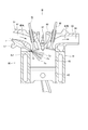
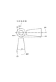
- FIG. 1 is a cross-sectional view showing a fuel injection valve according to the first embodiment.
- FIG. 2 is a diagram showing a state in which the fuel injection valve according to the first embodiment is applied to an internal combustion engine.
- FIG. 3 is a view of FIG. 2 from the direction of arrow III.
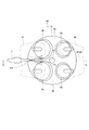
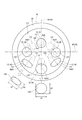
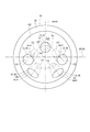
- FIG. 4 is a view of FIG. 1 from the direction of arrow IV.
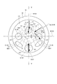
- FIG. 5 is a sectional view taken along line VV of FIG.
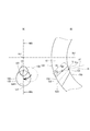
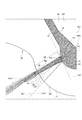
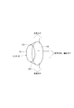
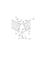
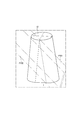
- FIG. 6 is a cross-sectional view showing the injection hole of the fuel injection valve according to the first embodiment and its vicinity.
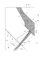
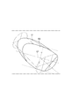
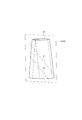
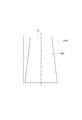
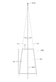
- FIG. 7 is a diagram for explaining how to define the inner wall intersection, the distance from the outlet opening to the inner wall intersection, and the injection hole length with respect to the injection hole of the fuel injection valve according to the first embodiment.
- FIG. 8 is a diagram for explaining how to define the inner wall intersection, the distance from the outlet opening to the inner wall intersection, and the injection hole length with respect to the injection hole of the fuel injection valve according to the first embodiment.
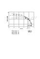
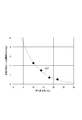
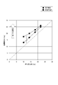
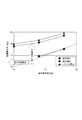
- FIG. 9 is a diagram showing the relationship between the atomization index and the position of the inner wall intersection with respect to the injection hole of the fuel injection valve according to the first embodiment.
- FIG. 10 is a cross-sectional view showing the injection hole of the fuel injection valve according to the second embodiment and its vicinity.
- FIG. 11 is a cross-sectional view showing the injection hole of the fuel injection valve according to the third embodiment and its vicinity.
- FIG. 12 is a cross-sectional view showing the injection hole of the fuel injection valve according to the fourth embodiment and its vicinity.
- FIG. 13 is a diagram showing the injection hole of the fuel injection valve according to the fifth embodiment and its vicinity.
- FIG. 14 is a diagram showing the injection hole of the fuel injection valve according to the sixth embodiment and its vicinity.
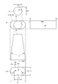
- FIG. 15 is a cross-sectional view including a perfect circular injection hole of the fuel injection valve according to the sixth embodiment.
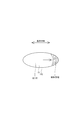
- FIG. 16 is a schematic view showing a perfect circular injection hole of the fuel injection valve according to the sixth embodiment.
- FIG. 17 is a schematic view showing a non-circular injection hole of the fuel injection valve according to the sixth embodiment.
- FIG. 18 is a schematic view showing a non-circular injection hole of the fuel injection valve according to the sixth embodiment.
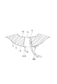
- FIG. 19 is a diagram showing a non-circular injection hole during fuel injection of the fuel injection valve according to the sixth embodiment.
- FIG. 20 is a cross-sectional view including a non-circular injection hole of the fuel injection valve according to the sixth embodiment.
- FIG. 21 is a cross-sectional view including a non-circular injection hole of the fuel injection valve according to the sixth embodiment.
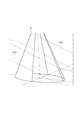
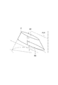
- FIG. 22 is a diagram for explaining a virtual non-true cone of the fuel injection valve according to the sixth embodiment.
- FIG. 23 shows the relationship between the “injection hole opening angle” of the non-circular injection hole of the fuel injection valve according to the sixth embodiment and the “fuel spray opening angle that increases due to the shape of the non-round injection hole”. It is a diagram showing FIG. 24 is a diagram for explaining how to define the injection hole shaft of the non-circular injection hole of the fuel injection valve according to the sixth embodiment.
- FIG. 25 is a diagram for explaining how to define the injection hole shaft of the non-circular injection hole of the fuel injection valve according to the sixth embodiment.
- FIG. 26 is a diagram for explaining how to define the injection hole shaft of the non-circular injection hole of the fuel injection valve according to the sixth embodiment.
- FIG. 24 is a diagram for explaining how to define the injection hole shaft of the non-circular injection hole of the fuel injection valve according to the sixth embodiment.
- FIG. 25 is a diagram for explaining how to define the injection hole shaft of the non-circular injection hole of the fuel injection valve according to the sixth embodiment.
- FIG. 26 is a diagram for explaining
- FIG. 27 is a diagram for explaining how to define the injection hole shaft of the non-circular injection hole of the fuel injection valve according to the sixth embodiment.
- FIG. 28 is a diagram for explaining how to define the injection hole shaft of the non-circular injection hole of the fuel injection valve according to the sixth embodiment.
- FIG. 29 is a diagram for explaining how to define the injection hole shaft of the non-circular injection hole of the fuel injection valve according to the sixth embodiment.
- FIG. 30 is a diagram showing the relationship between the “injection hole opening angle” and the “spray opening angle” of the fuel injection valve according to the sixth embodiment.
- FIG. 31 is a diagram showing a non-circular injection hole at the end of fuel injection of the fuel injection valve according to the sixth embodiment.
- FIG. 32 is a cross-sectional view showing a non-circular injection hole at the end of fuel injection of the fuel injection valve according to the sixth embodiment.
- FIG. 33 is a schematic view showing a non-circular injection hole of the fuel injection valve according to the seventh embodiment.
- FIG. 34 is a schematic view showing a non-circular injection hole of the fuel injection valve according to the seventh embodiment.
- FIG. 35 is a diagram for explaining how to define the injection hole shaft of the non-circular injection hole of the fuel injection valve according to the seventh embodiment.
- FIG. 36 is a diagram for explaining how to define the injection hole shaft of the non-circular injection hole of the fuel injection valve according to the seventh embodiment.
- FIG. 37 is a diagram for explaining how to define the injection hole shaft of the non-circular injection hole of the fuel injection valve according to the seventh embodiment.
- FIG. 38 is a diagram for explaining how to define the injection hole shaft of the non-circular injection hole of the fuel injection valve according to the seventh embodiment.
- FIG. 39 is a diagram for explaining how to define the injection hole shaft of the non-circular injection hole of the fuel injection valve according to the seventh embodiment.
- FIG. 40 is a diagram for explaining how to define the injection hole shaft of the non-circular injection hole of the fuel injection valve according to the seventh embodiment.
- FIG. 41 is a diagram showing the relationship between the “injection hole opening angle” and the “spray opening angle” of the fuel injection valve according to the seventh embodiment.
- FIG. 42 is a diagram showing the nozzle bottom and the injection hole of the fuel injection valve according to the eighth embodiment.
- FIG. 43 is a diagram showing an injection hole of the fuel injection valve according to the ninth embodiment and its vicinity.
- the fuel injection valve according to the first embodiment is shown in FIG.
- the fuel injection valve 1 is applied to, for example, a gasoline engine (hereinafter, simply referred to as “engine”) 80 as an internal combustion engine, and injects gasoline as fuel to supply the engine 80 (see FIG. 2).
- engine 80 a gasoline engine (hereinafter, simply referred to as “engine”) 80 as an internal combustion engine, and injects gasoline as fuel to supply the engine 80 (see FIG. 2).
- the engine 80 includes a cylindrical cylinder block 81, a piston 82, a cylinder head 90, an intake valve 95, an exhaust valve 96, and the like.
- the piston 82 is provided so as to be reciprocally movable inside the cylinder block 81.
- the cylinder head 90 is provided so as to close the open end of the cylinder block 81.
- a combustion chamber 83 is formed between the inner wall of the cylinder block 81, the wall surface of the cylinder head 90, and the piston 82. The volume of the combustion chamber 83 increases or decreases as the piston 82 reciprocates.
- the cylinder head 90 has an intake manifold 91 and an exhaust manifold 93.
- An intake passage 92 is formed in the intake manifold 91.
- One end of the intake passage 92 is open to the atmosphere, and the other end is connected to the combustion chamber 83.
- the intake passage 92 guides the air sucked from the atmosphere side (hereinafter, referred to as “intake”) to the combustion chamber 83.
- An exhaust passage 94 is formed in the exhaust manifold 93. One end of the exhaust passage 94 is connected to the combustion chamber 83, and the other end is open to the atmosphere.
- the exhaust passage 94 guides the air containing the combustion gas generated in the combustion chamber 83 (hereinafter, referred to as “exhaust”) to the atmosphere side.
- the intake valve 95 is provided on the cylinder head 90 so that it can reciprocate by rotating a cam of a driven shaft that rotates in conjunction with a drive shaft (not shown).
- the intake valve 95 can be opened and closed between the combustion chamber 83 and the intake passage 92 by reciprocating.
- the exhaust valve 96 is provided on the cylinder head 90 so that it can reciprocate by rotating the cam.
- the exhaust valve 96 can be opened and closed between the combustion chamber 83 and the exhaust passage 94 by reciprocating.
- the fuel injection valve 1 is mounted on the cylinder block 81 side of the intake passage 92 of the intake manifold 91.
- the fuel injection valve 1 is provided so that the center line is inclined with respect to the center line of the combustion chamber 83 or has a twisting relationship.
- the center line of the combustion chamber 83 is the axis of the combustion chamber 83 and coincides with the axis of the cylinder block 81.
- the fuel injection valve 1 is provided on the side of the combustion chamber 83. That is, the fuel injection valve 1 is mounted on the side of the engine 80 and used.
- a spark plug 97 as an ignition device is provided between the intake valve 95 and the exhaust valve 96 of the cylinder head 90, that is, at a position corresponding to the center of the combustion chamber 83.
- the spark plug 97 is provided at a position where the fuel injected from the fuel injection valve 1 does not directly adhere, and at a position where the air-fuel mixture (combustible air) in which the fuel and the intake air are mixed can be ignited.
- the engine 80 is a direct injection type gasoline engine.
- the fuel injection valve 1 is provided so that a plurality of injection holes 13 are exposed on the radial outer portion of the combustion chamber 83.
- the fuel injection valve 1 is supplied with fuel pressurized to the fuel injection pressure by a fuel pump (not shown). Conical fuel spray Fo is injected into the combustion chamber 83 from the plurality of injection holes 13 of the fuel injection valve 1.
- two intake valves 95 and two exhaust valves 96 are provided in the engine 80.
- the two intake valves 95 are provided at the two branched ends of the intake manifold 91 on the cylinder block 81 side, respectively.
- the two exhaust valves 96 are provided at the two branched ends of the exhaust manifold 93 on the cylinder block 81 side, respectively.
- the fuel injection valve 1 is provided in the intake manifold 91 so that the center line is along the virtual plane VP100 that includes the shaft of the cylinder block 81 and passes between the two intake valves 95 and between the two exhaust valves 96.
- the fuel injection valve 1 includes a nozzle 10, a housing 20, a needle 30, a movable core 40, a fixed core 51, a spring 52 as a valve seat side urging member, a spring 53 as a fixed core side urging member, and a coil as a drive unit. It is equipped with 55 mag.
- the nozzle 10 is made of a metal such as martensitic stainless steel.
- the nozzle 10 is hardened so as to have a predetermined hardness. As shown in FIGS. 1, 4 and 5, the nozzle 10 has a nozzle cylinder portion 11, a nozzle bottom portion 12, a nozzle hole 13, a valve seat 14, and the like.
- the nozzle cylinder portion 11 is formed in a substantially cylindrical shape.
- the nozzle bottom portion 12 closes one end of the nozzle cylinder portion 11.
- the injection hole 13 is formed so as to connect the surface of the nozzle bottom 12 on the nozzle cylinder portion 11 side, that is, the inner wall, and the surface 122 on the side opposite to the nozzle cylinder portion 11 (see FIG. 5).
- a plurality of injection holes 13 are formed in the bottom portion 12 of the nozzle. In this embodiment, six injection holes 13 are formed (see FIG. 4).
- the valve seat 14 is formed in an annular shape around the injection hole 13 on the surface of the nozzle bottom 12 on the nozzle cylinder 11 side. The injection hole 13 will be described in detail later.
- the housing 20 has a first cylinder member 21, a second cylinder member 22, a third cylinder member 23, an inlet portion 24, and the like.
- the first cylinder member 21, the second cylinder member 22, and the third cylinder member 23 are all formed in a substantially cylindrical shape.
- the first cylinder member 21, the second cylinder member 22, and the third cylinder member 23 are arranged so as to be coaxial in the order of the first cylinder member 21, the second cylinder member 22, and the third cylinder member 23, and are connected to each other. ..
- the first cylinder member 21 and the third cylinder member 23 are formed of a magnetic material such as ferritic stainless steel and are subjected to a magnetic stabilization treatment.
- the second tubular member 22 is made of a non-magnetic material such as austenitic stainless steel.
- the second cylinder member 22 functions as a magnetic throttle portion.
- the first cylinder member 21 is provided so that the inner wall at the end opposite to the second cylinder member 22 fits into the outer wall of the nozzle cylinder portion 11 of the nozzle 10.
- the inlet portion 24 is formed in a tubular shape with a magnetic material such as ferritic stainless steel. The inlet portion 24 is provided so that one end is connected to the end portion of the third cylinder member 23 opposite to the second cylinder member 22.
- a fuel passage 100 is formed inside the housing 20.
- the fuel passage 100 is connected to the injection hole 13. That is, the nozzle cylinder portion 11 of the nozzle 10 forms a fuel passage 100 inside.
- a pipe (not shown) is connected to the inlet portion 24 on the opposite side of the third cylinder member 23. As a result, fuel from the fuel supply source (fuel pump) flows into the fuel passage 100 via the pipe.
- the fuel passage 100 guides fuel to the injection hole 13.
- a filter 25 is provided inside the inlet portion 24.
- the filter 25 collects foreign matter in the fuel flowing into the fuel passage 100.
- the needle 30 is formed in a rod shape by, for example, a metal such as martensitic stainless steel.
- the needle 30 is hardened so as to have a predetermined hardness.
- the needle 30 is housed in the housing 20 so that it can reciprocate in the fuel passage 100 in the axial direction of the housing 20.
- the needle 30 has a needle body 301, a seat portion 31, a large diameter portion 32, a flange portion 34, and the like.
- the needle body 301 is formed in a rod shape.
- the seat portion 31 is formed at the end portion of the needle body 301 on the nozzle 10 side and can come into contact with the valve seat 14.
- the large diameter portion 32 is formed in the vicinity of the seat portion 31 at the end of the needle body 301 on the valve seat 14 side.
- the outer diameter of the large diameter portion 32 is set to be larger than the outer diameter of the end portion of the needle body 301 on the valve seat 14 side.
- the large diameter portion 32 is formed so that the outer wall slides on the inner wall of the nozzle cylinder portion 11 of the nozzle 10. As a result, the needle 30 is guided to reciprocate in the axial direction at the end portion on the valve seat 14 side.
- the large-diameter portion 32 is formed with notches 33 so that a plurality of portions in the circumferential direction of the outer wall are notched. As a result, the fuel can flow between the notch 33 and the inner wall of the nozzle cylinder 11.
- the collar portion 34 is formed in a substantially cylindrical shape so as to extend radially outward from the end portion of the needle body 301 opposite to the seat portion 31.
- Axial hole portion 35 and radial hole portion 36 are formed in the needle body 301.
- the axial hole portion 35 is formed so as to extend in the axial direction from the end surface of the needle body 301 opposite to the seat portion 31.
- the radial hole portion 36 is formed so as to extend in the radial direction of the needle main body 301 to connect the axial hole portion 35 and the outer wall of the needle main body 301.
- the needle 30 opens and closes the injection hole 13 when the seat portion 31 separates from the valve seat 14 (separates) or comes into contact with the valve seat 14 (seating).
- the direction in which the needle 30 is separated from the valve seat 14 is referred to as a valve opening direction
- the direction in which the needle 30 abuts on the valve seat 14 is referred to as a valve closing direction.
- the movable core 40 is formed in a tubular shape with a magnetic material such as ferritic stainless steel.
- the movable core 40 is subjected to a magnetic stabilization process.
- the movable core 40 is provided inside the first cylinder member 21 and the second cylinder member 22 of the housing 20.
- the movable core 40 is formed in a substantially columnar shape.
- the movable core 40 is formed with a recess 41, a shaft hole 42, and a through hole 43.
- the recess 41 is formed so as to be recessed from the center of the end surface of the movable core 40 on the nozzle 10 side to the side opposite to the nozzle 10.
- the shaft hole 42 is formed so as to connect the end surface of the movable core 40 opposite to the nozzle 10 and the bottom surface of the recess 41 so as to pass through the shaft of the movable core 40.
- the through hole 43 is formed so as to connect the end surface of the movable core 40 on the nozzle 10 side and the end surface of the movable core 40 on the side opposite to the nozzle 10.
- a plurality of through holes 43 are formed at equal intervals in the circumferential direction of the movable core 40 on the radial outer side of the recess 41.
- the movable core 40 is provided inside the housing 20 with the needle body 301 inserted through the shaft hole 42. That is, the movable core 40 is provided on the outer side in the radial direction of the needle body 301. The movable core 40 can move relative to the needle body 301 in the axial direction. The inner wall forming the shaft hole 42 of the movable core 40 is slidable with the outer wall of the needle body 301.
- the portion of the end face on the opposite side of the nozzle 10 around the shaft hole 42 can be in contact with the end face on the nozzle 10 side of the collar portion 34 or separated from the end face on the nozzle 10 side of the collar portion 34. Is.
- the fixed core 51 is formed in a substantially cylindrical shape with a magnetic material such as ferritic stainless steel.
- the fixed core 51 is magnetically stabilized.
- the fixed core 51 is provided on the side of the movable core 40 opposite to the nozzle 10.
- the fixed core 51 is provided inside the housing 20 so that the outer wall is connected to the inner walls of the second cylinder member 22 and the third cylinder member 23.
- the end face of the fixed core 51 on the nozzle 10 side can come into contact with the end face of the movable core 40 on the fixed core 51 side.
- a cylindrical adjusting pipe 54 is press-fitted inside the fixed core 51.
- the spring 52 is, for example, a coil spring, and is provided between the adjusting pipe 54 and the needle 30 inside the fixed core 51.
- One end of the spring 52 is in contact with the adjusting pipe 54.
- the other end of the spring 52 is in contact with the end faces of the needle body 301 and the flange 34 on the opposite side of the nozzle 10.
- the spring 52 can urge the movable core 40 together with the needle 30 toward the nozzle 10 side, that is, in the valve closing direction. The urging force of the spring 52 is adjusted by the position of the adjusting pipe 54 with respect to the fixed core 51.
- the coil 55 is formed in a substantially cylindrical shape, and is provided so as to surround the radial outside of the second cylinder member 22 and the third cylinder member 23 of the housing 20 in particular. Further, a tubular holder 26 is provided on the outer side of the coil 55 in the radial direction so as to cover the coil 55.
- the holder 26 is made of a magnetic material such as ferritic stainless steel. In the holder 26, the inner wall at one end is connected to the outer wall of the first cylinder member 21, and the inner wall at the other end is magnetically connected to the outer wall of the third cylinder member 23.
- the coil 55 generates a magnetic force when electric power is supplied (energized).
- a magnetic force is generated in the coil 55, a magnetic circuit is formed in the movable core 40, the first cylinder member 21, the holder 26, the third cylinder member 23, and the fixed core 51, avoiding the second cylinder member 22 as the magnetic throttle portion.
- a magnetic attraction force is generated between the fixed core 51 and the movable core 40, and the movable core 40 is attracted to the fixed core 51 side together with the needle 30.
- the needle 30 moves in the valve opening direction, the seat portion 31 is separated from the valve seat 14, and the valve is opened.
- the injection hole 13 is opened, and fuel is injected from the injection hole 13.
- the movable core 40 can be attracted to the fixed core 51 side and the needle 30 can be moved to the side opposite to the valve seat 14, that is, in the valve opening direction.
- the movable core 40 is attracted to the fixed core 51 side (valve opening direction) by the magnetic attraction force, the end face on the fixed core 51 side collides with the end face on the movable core 40 side of the fixed core 51. As a result, the movable core 40 is restricted from moving in the valve opening direction.
- the spring 53 is, for example, a coil spring, and is provided in a state where one end is in contact with the bottom surface of the recess 41 of the movable core 40 and the other end is in contact with the stepped surface of the inner wall of the first cylinder member 21 of the housing 20. ..
- the spring 53 can urge the movable core 40 toward the fixed core 51, that is, in the valve opening direction.
- the urging force of the spring 53 is smaller than the urging force of the spring 52. Therefore, when the coil 55 is not energized, the seat portion 31 of the needle 30 is pressed against the valve seat 14 by the spring 52, and the movable core 40 is pressed against the collar portion 34 by the spring 53.
- the radial outer side of the third cylinder member 23 is molded by a mold portion 56 made of resin.
- the connector portion 57 is formed so as to project radially outward from the mold portion 56.
- a terminal 571 for supplying electric power to the coil 55 is insert-molded in the connector portion 57.
- the fuel flowing in from the inlet portion 24 is the inside of the filter 25, the fixed core 51 and the adjusting pipe 54, the axial hole portion 35, the radial hole portion 36, between the needle 30 and the inner wall of the housing 20, the needle 30 and the nozzle. It flows between the inner wall of the tubular portion 11, that is, the fuel passage 100, and is guided to the injection hole 13.
- the periphery of the movable core 40 and the needle 30 is filled with fuel. Further, when the fuel injection valve 1 is operated, fuel flows through the through hole 43 of the movable core 40, the axial hole portion 35 of the needle 30, and the radial hole portion 36. Therefore, the movable core 40 and the needle 30 can smoothly reciprocate in the axial direction inside the housing 20.
- the fuel pressure in the fuel passage 100 assumed when the fuel injection valve 1 of the present embodiment is used is, for example, 1 MPa or more. This embodiment is more advantageous as the pressure of the fuel in the fuel passage 100 becomes as high as 30 MPa or 100 MPa.
- the minimum value of the flow path area between the valve seat 14 and the needle 30 when the needle 30 is most separated from the valve seat 14 is the seat throttle area As, and the minimum value of the flow path area of the injection hole 13 is set.
- the nozzle aperture area is Ah, As> Ah.
- the seat drawing area As is a state in which the seat portion 31 of the needle 30 is most distant from the valve seat 14, that is, the end surface of the movable core 40 on the fixed core 51 side is in contact with the fixed core 51 and the flange portion 34.
- the injection hole throttle area Ah corresponds to the minimum value of the total area of the flow paths of all the six injection holes 13. That is, the injection hole throttle area Ah is the total area of the minimum values of the flow path areas perpendicular to the injection hole axis Axh1 of each injection hole 13.
- the injection hole 13 of the present embodiment will be described in detail.
- the needle 30 is not shown.
- the nozzle 10 has a sack wall surface 150, an inlet opening 131, an outlet opening 132, an inner wall of the injection hole 133, an injection hole 13, and a valve seat 14.
- the sack wall surface 150 is recessed from the center of the surface 121 on the nozzle cylinder 11 side of the nozzle bottom 12 to the side opposite to the nozzle cylinder 11, and forms a sack chamber 15 inside.
- the sack chamber 15 is formed between the sack wall surface 150 and the seat portion 31 of the needle 30.
- the valve seat 14 is formed in an annular shape around the sack wall surface 150 of the surface 121.
- the valve seat 14 is formed in a tapered shape so as to approach the axis Ax1 of the nozzle cylinder portion 11 from the nozzle cylinder portion 11 side toward the sack wall surface 150 side.
- the injection hole 13 connects the sack wall surface 150 and the surface 122 of the nozzle bottom 12 opposite to the nozzle cylinder portion 11 to inject fuel in the fuel passage 100.
- the sack wall surface 150 is formed in a curved surface shape.
- the injection hole 13 is the inlet opening 131 formed on the sack wall surface 150, which is the surface of the nozzle bottom 12 on the nozzle cylinder 11 side, and the nozzle bottom 12 on the opposite side of the nozzle cylinder 11. It has an outlet opening 132 formed on the surface 122, and a nozzle inner wall 133 connecting the inlet opening 131 and the outlet opening 132.
- the inlet opening 131 means a closed area as a virtual surface formed along the sack wall surface 150 by making a hole (injection hole 13) in the nozzle bottom portion 12, and the area of this area. Is the area of the entrance opening 131.
- the outlet opening 132 is closed as a virtual surface formed along the surface 122 of the nozzle bottom 12 opposite to the nozzle cylinder portion 11 by making a hole (injection hole 13) in the nozzle bottom 12. The area of this area is defined as the area of the outlet opening 132. In each of the six injection holes 13, the area of the outlet opening 132 is larger than the area of the inlet opening 131.
- the six injection holes 13 are formed in a taper shape so that the injection hole inner wall 133 is separated from the injection hole shaft Axh1, which is the axis of the injection hole 13, as the injection hole inner wall 133 moves from the inlet opening 131 side to the outlet opening 132 side. ing.
- the six injection holes 13 correspond to "tapered injection holes”.
- each of the six injection holes 13 is referred to as injection holes 61, 62, 63, 64, 65, 66.
- the centers of the inlet openings 131 of the injection holes 61, 62, 63, 64, 65, 66 are arranged at equal intervals on the pitch circle Cp1 centered on the axis Ax1.
- the injection holes 61 and 64 are formed on the virtual plane VP101 including the shaft Ax1 of the nozzle cylinder portion 11 so that the shaft Ax1 of the nozzle cylinder portion 11 is located between them. That is, the virtual plane VP101 passes through the injection holes 61 and 64. Further, the injection holes 61 and 64 are formed so that the respective injection hole axes Axh1 are included in the virtual plane VP101. In the nozzle holes 61 and 64, the nozzle shaft Axh1 intersects the shaft Ax1 of the nozzle cylinder portion 11, and the nozzle shaft Axh1 is not twisted with respect to the shaft Ax1 (see FIG. 4).
- the inlet openings 131 of the injection holes 62 and 66 are formed on the injection hole 61 side with respect to the virtual plane VP102 including the axis Ax1 of the nozzle cylinder portion 11 and perpendicular to the virtual plane VP101.
- the inlet openings 131 of the injection holes 63 and 65 are formed on the injection hole 64 side with respect to the virtual plane VP102.
- the nozzle shaft Axh1 does not intersect the shaft Ax1 of the nozzle cylinder portion 11, and the nozzle shaft Axh1 has a twisting relationship with respect to the shaft Ax1 (see FIG. 4). ..
- the normal Ln1 of the sack wall surface 150 at the opening intersection Po1 which is the intersection of the injection hole axis Axh1 and the inlet opening 131 is the injection hole inner wall 133 or the injection hole inner wall 133.
- the distance from the outlet opening 132 to the inner wall intersection Pw1 which is the intersection of the normal Ln1 and the injection hole inner wall 133 or the virtual inner wall VW1 is determined. If the injection hole length, which is the length between the inlet opening 131 and the outlet opening 132 of the injection hole inner wall 133 on the side where the LA and the inner wall intersection Pw1 is formed, is LB, the injection hole 13 is LA / LB>. It is formed to be -0.2. More specifically, the injection hole 13 is formed so that 1> LA / LB> ⁇ 0.2.
- LA when the normal line Ln1 intersects the injection hole inner wall 133 (see FIG. 6), LA takes a positive value. Therefore, LA / LB is a positive value. On the other hand, when the normal Ln1 intersects the virtual inner wall VW1, LA takes a negative value. Therefore, LA / LB has a negative value.
- the normal Ln1 intersects with the injection hole inner wall 133 on the shaft Ax1 side of the nozzle cylinder portion 11 among the two injection hole inner walls 133 shown in the cross section by the virtual surface Sc1.
- the direction of the normal line Ln1 is determined by the shape of the sack wall surface 150 on which the entrance opening 131 is formed.
- a gasoline engine having a spark plug needs to be provided with a jet hole toward the ignition source and a jet hole for forming a uniform spray in the cylinder even if it is mounted on the side as well as on the center.
- the injection direction rarely coincides with the radial direction of the valve shaft (axis Ax1), and at least one of the injection holes has a twist.
- the projection angle ⁇ p1 between the extension line Le1 connecting the axis Ax1 of the nozzle cylinder portion 11 and the center of the inlet opening 131 and the injection hole axis Axh1 is 0 °.
- the normal line Ln1 and the injection are performed.
- the intersection with the hole inner wall 133 is the inner wall intersection Pw1
- the distance from the outlet opening 132 to the inner wall intersection Pw1 is LA
- the length between is defined as the injection hole length LB.
- the sheet drawing area As is larger than the injection hole drawing area Ah. Therefore, when the seat portion 31 of the needle 30 is separated from the valve seat 14, the fuel flows into the sack chamber 15 in a state where there is almost no throttle by the seat portion 31 and the pressure loss is small. As a result, the pressure vector acts in the normal Ln1 direction. Therefore, the fuel is injected in the normal Ln1 direction. Further, in the present embodiment, the normal line Ln1 and the injection hole inner wall 133 intersect. Therefore, a liquid film of fuel is formed in the injection hole 13.
- FIG. 6 shows the state in the sack chamber 15 and the injection hole 13 when the seat portion 31 of the needle 30 is most separated from the valve seat 14.
- hatching of the cross section of the member is omitted in order to avoid complicating the drawing.
- the darker the shaded area the higher the pressure.
- the pressure of the sack chamber 15 is high, and the pressure of the portion of the injection hole 13 on the inlet opening 131 side from the inner wall intersection Pw1 which is the intersection of the normal Ln1 and the injection hole inner wall 133 is high. I understand.
- the fuel flow generated at the inlet opening 131 can collide with the injection hole inner wall 133, and the pressure in the sack chamber 15 can be efficiently converted into energy for forming a liquid film, and the fuel can be atomized. Is possible.
- the effect of the fuel injection valve 1 of the present embodiment is shown by the atomization index based on the Fraser model.
- the volume average particle size D 30 after splitting of the fuel is calculated by the following equation 1.
- D 30 3.78 (2 / E) 1/3 (hr / V 2 ) 1/3 ( ⁇ 2 / ⁇ L ⁇ a ) 1/6 ... Equation 1
- Equation 1 E, h, r, V, ⁇ , ⁇ L , and ⁇ a are experimental constants, liquid film thickness, distance, liquid film velocity, surface tension, fuel density, and air density, respectively.
- the projection angle ⁇ p1 that is, the injection hole 13 whose twist angle (see FIG. 4) is 0 °, 30 °, and 60 °.
- the relationship between the atomization index and LA / LB is as shown in FIG.
- FIG. 9 shows the values obtained by analysis. It should be noted that what is obtained in the analysis is the liquid film thickness and the liquid film velocity.
- the atomization index is a value based on the liquid film velocity (spray rate) and the liquid film thickness, and the smaller the atomization index, the finer the fuel spray is.
- the injection hole 13 is formed so that LA / LB> -0.2. Therefore, the fuel spray injected from the injection hole 13 can be effectively atomized.
- the fuel in the sack chamber 15 is not easily affected by the inflow from the valve seat 14 side, a flow velocity is generated in the normal Ln1 direction at the inlet opening 131, and the nozzle cylinder Even in the injection hole 13 in which the injection hole axis Axh1 has a twisting relationship with respect to the axis Ax1 of the portion 11, it depends on the kinetic energy when colliding with the injection hole inner wall 133, so that the atomization index (movement in the X, Y, Z directions) It depends on energy) and can be organized.
- the minimum value of the flow path area between the valve seat 14 and the needle 30 when the needle 30 is most separated from the valve seat 14 is the seat throttle area As and the flow of the injection hole 13.
- the minimum value of the road area is the injection hole throttle area Ah, As> Ah.
- the normal Ln1 of the sack wall surface 150 at the opening intersection Po1 which is the intersection of the injection hole shaft Axh1 and the inlet opening 131 has the injection hole inner wall 133 or the injection hole inner wall 133 with the nozzle cylinder portion 11. It is formed so as to intersect the virtual inner wall VW1 extending to the opposite side.
- the distance from the outlet opening 132 to the inner wall intersection Pw1 which is the intersection of the normal Ln1 and the injection hole inner wall 133 or the virtual inner wall VW1 in the cross section by the virtual surface Sc1 including the injection hole axis Axh1 is LA.
- the injection hole length which is the length between the inlet opening 131 and the outlet opening 132 of the injection hole inner wall 133 on the side where the inner wall intersection Pw1 is formed, is LB
- the injection hole 13 is LA / LB>-. It is formed to be 0.2. Therefore, the high-pressure fuel can be effectively collided with the injection hole inner wall 133, and the liquid film can be effectively formed in the injection hole 13. Therefore, the fuel spray Fo injected from the injection hole 13 can be atomized more effectively.
- the normal line Ln1 intersects with the injection hole inner wall 133 on the axis Ax1 side of the nozzle cylinder portion 11 among the two injection hole inner walls 133 shown in the cross section by the virtual surface Sc1. Even with such a configuration, the liquid film is effectively formed in the injection hole 13 by the high-pressure fuel colliding with the injection hole inner wall 133. Therefore, the pressure energy of the fuel can be utilized to effectively atomize the fuel spray Fo injected from the injection hole 13.
- FIG. 10 A part of the fuel injection valve according to the second embodiment is shown in FIG.
- the configuration of the nozzle 10 is different from that in the first embodiment.
- the shape of the sack wall surface 150 on which the entrance opening 131 is formed is different from that of the first embodiment. Therefore, the normal line Ln1 intersects the injection hole inner wall 133 on the valve seat 14 side, that is, the side opposite to the axis Ax1 of the nozzle cylinder portion 11 among the two injection hole inner walls 133 shown in the cross section by the virtual surface Sc1 (FIG. 10). Even with such a configuration, the liquid film is effectively formed in the injection hole 13 by the high-pressure fuel colliding with the injection hole inner wall 133. Therefore, the pressure energy of the fuel can be utilized to effectively atomize the fuel spray Fo injected from the injection hole 13.
- the second embodiment has the same configuration as the first embodiment except for the above points.
- FIG. 10 A part of the fuel injection valve according to the third embodiment is shown in FIG.
- the configuration of the nozzle 10 is different from that in the first embodiment.
- the curvature of the sack wall surface 150 in the cross section including the axis Ax1 of the nozzle cylinder portion 11 is different from that in the first embodiment. Therefore, in the present embodiment, the position of the inner wall intersection Pw1 which is the intersection of the normal line Ln1 and the injection hole inner wall 133 is different from that of the first embodiment.
- the normal line Ln1 intersects the nozzle inner wall 133 on the axis Ax1 side of the nozzle cylinder portion 11 among the two nozzle inner walls 133 shown in the cross section by the virtual surface Sc1. .. Even with such a configuration, the liquid film is effectively formed in the injection hole 13 by the high-pressure fuel colliding with the injection hole inner wall 133. Therefore, the pressure energy of the fuel can be utilized to effectively atomize the fuel spray Fo injected from the injection hole 13.
- the third embodiment has the same configuration as the first embodiment except for the above-mentioned points.
- FIG. 10 A part of the fuel injection valve according to the fourth embodiment is shown in FIG.
- the configuration of the nozzle 10 is different from that in the first embodiment.
- the sack wall surface 150 is formed in a tapered shape so as to approach the axis Ax1 of the nozzle cylinder portion 11 from the nozzle cylinder portion 11 side toward the nozzle bottom portion 12 side.
- the entrance opening 131 is formed on the tapered sack wall surface 150.
- the normal line Ln1 intersects with the injection hole inner wall 133 on the axis Ax1 side of the nozzle cylinder portion 11 among the two injection hole inner walls 133 shown in the cross section by the virtual surface Sc1.
- the fourth embodiment has the same configuration as the first embodiment except for the above points.
- the center of the inlet opening 131 of the injection holes 61, 62, 64, 66 is arranged on the pitch circle Cp1 centered on the axis Ax1.
- the center of the inlet opening 131 of the injection holes 63 and 65 is arranged outside the pitch circle Cp1.
- FIGS. 14 and 15 A part of the fuel injection valve according to the sixth embodiment is shown in FIGS. 14 and 15.
- the configuration of the injection hole 13 and the like are different from those in the first embodiment.
- the pressure of the fuel in the fuel passage 100 assumed when the fuel injection valve 1 of the present embodiment is used is, for example, about 20 MPa.
- the injection hole 13 of the present embodiment will be described in detail.
- the needle 30 is not shown.
- the angle formed by the two injection hole inner walls 133 of the injection hole 13 of 1 is referred to as the “injection hole opening angle”.
- the angle formed by the two contours of the fuel spray Fo injected from the injection hole 13 of 1 is referred to as the “fuel spray opening angle”.
- the injection holes 63 and 65 have an elliptical shape, that is, a non-perfect circular shape when viewed from the injection hole axis Axh1 direction (see FIG. 14).
- the injection holes 63 and 65 are referred to as "non-round injection holes”.
- the injection holes 63 and 65 are appropriately referred to as "oval injection holes” or "elliptical injection holes”.
- the "oval injection hole” is an injection hole in which the shape of the outlet opening 132 is non-round and has an oval shape such as an egg shape, an ellipse, or a track shape.
- An ellipse is a circle with a constant sum of distances from two focal points.
- the shape of the outlet openings 132 of the injection holes 63 and 65 is an ellipse having two focal points.
- the outlet opening 132 includes an injection hole 13 having an egg-shaped, elliptical or track shape.
- the "non-round injection hole” shall include an "oval injection hole", an "elliptical injection hole”, and a "track injection hole”.
- the "longest diameter” means the longest width among the widths of the shape, and the shape of the outlet opening 132 of the injection holes 63 and 65 corresponds to the length of the long axis.
- the "shortest diameter” means the shortest width among the widths of the shape, and the shape of the outlet openings 132 of the injection holes 63 and 65 corresponds to the length of the minor axis.
- the ratio of the longest diameter a2 of the outlet opening 132 to the shortest diameter b2 is 1. Therefore, in the injection holes 61, 62, 64, 66, the shape of the outlet opening 132 is a perfect circle when viewed from the injection hole axis Axh1 direction (see FIG. 14).
- the injection holes 61, 62, 64, 66 are referred to as "round injection holes”.
- one or more (two) of the plurality of injection holes 13 has a injection hole 13 in which the ratio of the longest diameter to the shortest diameter of the outlet opening 132 is larger than 1. It is a non-round injection hole.
- the shapes of the inlet opening 131 and the outlet opening 132 are perfectly circular. Further, the inlet opening 131 and the outlet opening 132 are formed coaxially. Therefore, in the cross section formed by the first virtual plane VP1 which is a virtual plane including the injection hole axis Axh1, the angle ⁇ formed by the injection hole inner wall 133 is constant in the circumferential direction of the outlet opening 132.
- the injection holes 63 and 65 as non-circular injection holes have an elliptical shape of the inlet opening 131 and the outlet opening 132. Further, the inlet opening 131 and the outlet opening 132 are formed coaxially so that the directions of the major axis and the minor axis coincide with each other. Therefore, in the cross section by the second virtual plane VP2 which is a virtual plane including the injection hole axis Axh1, the angle at which the angle formed by the injection hole inner wall 133 is maximized is ⁇ 1, and the third virtual plane which is the virtual plane including the injection hole axis Axh1. In the cross section by VP3, assuming that the angle formed by the inner wall of the injection hole 133 is ⁇ 2, the second virtual plane VP2 and the third virtual plane VP3 are orthogonal to each other.
- the non-round injection hole has an elliptical shape in which the inlet opening 131 and the outlet opening 132 have the same flatness.
- the "major axis” means the longest width among the widths of the shape, and corresponds to the "major axis” in the ellipse.
- the “minor axis” means the shortest width of the shape and corresponds to the "minor axis” in the ellipse.
- the injection holes 63 and 65 as the non-circular injection holes are formed so that the minor axis direction of the outlet opening 132 is along the injection direction of the fuel injected from the non-round injection hole. There is.
- the minor axis direction and the injection direction coincide with each other, the minor axis is on a virtual plane passing through the injection hole axis Axh1 and parallel to the axis Ax1.
- the "minor axis direction” corresponds to the minor axis of the outlet opening 132, that is, the direction along the minor axis when viewed from the axis Ax1 direction of the nozzle cylinder portion 11.
- the "fuel injection direction” corresponds to the direction along the injection hole axis Axh1 when viewed from the axis Ax1 direction of the nozzle cylinder portion 11.
- the "major axis direction” corresponds to the major axis of the outlet opening 132, that is, the direction along the major axis.
- the injection hole opening angle of the perfect circular injection hole (64), which is the injection hole 13 in which the ratio of the longest diameter to the shortest diameter of the outlet opening 132 among the plurality of injection holes 13 is 1, is ⁇ ( deg)
- the opening angle of the fuel spray Fo injected from the perfect circular injection hole is ⁇ f (deg)
- the average pressure of the fuel in the fuel passage 100 when the fuel is injected from the perfect circular injection hole is P (MPa).
- the virtual cone is defined as a virtual true cone Vc1 (see FIG. 15).
- " ⁇ " represents a power.
- P 20 (MPa)
- 0.5 ⁇ P ⁇ 0.6 is about 3.0.
- the maximum injection hole opening angle of the non-round injection hole (63) is ⁇ 1 (deg)
- the minimum injection hole opening angle is ⁇ 2 (deg)
- the injection is performed from the non-round injection hole.
- the maximum opening angle of the fuel spray Fo is ⁇ f1 (deg)
- the minimum opening angle of the fuel spray Fo injected from the non-circular injection hole is ⁇ f2 (deg).
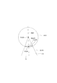
- the intersection of the injection hole axis Axh1 of the non-circular injection hole and the outlet opening 132 is defined as the apex Pv2, and the angle formed by the two generatrix in the cross section by the second virtual plane VP2 including the injection hole axis Axh1 of the non-round injection hole
- ⁇ f2 ⁇ 2 + 0.5 ⁇ P ⁇ 0.
- the virtual cone is defined as the virtual non-true cone Vc2 (see FIGS. 20, 21, 22)
- at least two adjacent injection holes 13 among the six injection holes 13 are the virtual true cone Vc1 or the virtual non-true cone.
- the cone Vc2 is formed so as not to interfere with the virtual true cone Vc1 or the virtual non-true cone Vc2.
- all of the six injection holes 13 are formed so that the virtual true cone Vc1 or the virtual non-true cone Vc2 does not interfere with the virtual true cone Vc1 or the virtual non-true cone Vc2. There is.
- FIG. 23 shows the “injection hole opening angle” ( ⁇ 1) when the “injection hole opening angle” ( ⁇ 1) is changed and the “increased fuel spray opening due to the shape of the non-circular injection hole”.
- This is an experimental result showing the relationship with "angle" (non-round injection hole + ⁇ spray opening angle).
- the larger the “injection hole opening angle” ( ⁇ 1) the smaller the “fuel spray opening angle that increases due to the shape of the non-circular injection hole”.
- LCs1 corresponds to "17 x e ⁇ (-0.13 x ⁇ 1)" in the above formula 3.
- a sphere B101 centered on the apex Pv101 set in step 3 is created, and a surface formed inside the intersection line Lx101 between the sphere B101 and the virtual cone Vc101 (inner wall 133 of the injection hole) is virtualized.
- the surface is VPx101.
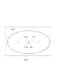
- the straight line connecting the point Pt101 (see FIG. 29) that divides the straight line L101 passing through the portion having the longest width of the virtual surface VPx101 and the apex Pv101 is the injection hole axis Axh1.
- the opening angle (spray opening angle) of the fuel spray injected from the perfect circular injection hole is set to the "injection hole opening angle” and the "opening angle of the fuel spray increased by the fuel pressure in the fuel passage 100".
- the size is the sum of "0.5 x P ⁇ 0.6" corresponding to "”.
- For the opening angle (spray opening angle) of the fuel spray injected from the non-circular injection hole add “0.5 x P ⁇ 0.6" to the "injection hole opening angle” on the major axis side, and further , The size is the sum of "17 x e ⁇ (-0.13 x ⁇ 1)" corresponding to "the opening angle of the fuel spray increased due to the shape of the non-round injection hole”.
- the opening angle of the fuel spray injected from the non-circular injection hole is larger than the opening angle of the fuel spray injected from the perfect circular injection hole as compared with the major axis side.
- the non-circular injection hole Due to the widening of the spray angle of the non-circular injection hole, the length of the fuel spray injected from the non-round injection hole becomes shorter than the length of the fuel spray injected from the perfect circular injection hole. Therefore, it can be said that the non-circular injection hole has a higher effect of lowering the penetration of the fuel spray than the perfect circular injection hole.
- the injection holes 61, 62, 64, 66 as perfect circular injection holes and the injection holes 63, 65 as non-round injection holes are arranged as shown in FIG. 14, and all the injection holes 13 (Injection holes 61 to 66) are formed so that the virtual non-true cone Vc2 and the virtual true cone Vc1 or the virtual non-true cone Vc2 do not interfere with each other. Therefore, a closed space is not formed between the fuel sprays, no negative pressure is generated, and air can be introduced. As a result, it is possible to prevent the fuel sprays from contracting and coalescing. Therefore, it is possible to suppress the wetting in the cylinder and the deterioration of the spray characteristics due to the high penetration of the spray.
- the accumulation of the deposit on the inner wall 133 of the injection hole is suppressed, the penetration of the fuel spray is reduced, and the fuel sprays injected from the injection hole 13 do not interfere with each other.
- the injection hole 13 By forming the injection hole 13 and appropriately setting the injection hole opening angle, it is possible to suppress wetting in the cylinder and deterioration of the spray characteristics due to high penetration of the spray.
- the fuel in the non-round injection hole, during fuel injection, the fuel is extended in the major axis direction (major axis side) and the fuel is ejected in the form of a liquid film to promote division and spray the fuel. Can be atomized.
- the fuel in the injection hole collects in the R portion in the major axis direction (major axis side) and is ejected in the form of a liquid thread, resulting in poor fuel sharpness. , The wetness around the injection hole on the outer wall of the nozzle 10 may increase (see FIGS. 31 and 32).
- the flatness a1 / b1 (> 1) of the outlet opening 132 of the injection hole 63 as a non-circular injection hole is the outlet opening 132 of the injection hole 64 as a perfect circular injection hole.
- the area of the inlet opening 131 of the non-round injection hole (63, 65) having a large flatness of the outlet opening 132 is such that the perfect circular injection hole (61, 62, 64,) having a small flatness of the outlet opening 132. It is smaller than the area of the entrance opening 131 of 66).
- the area of the inlet opening 131 is small, so that it is difficult for fuel to flow, and the flatness of the outlet opening 132 is large. , 65), as well as air flowing into the sack chamber 15, fuel can easily flow from the large area of the inlet opening 131, and the flatness of the outlet opening 132 is small from the perfect circular injection holes (61, 62, 64, 66).
- the fuel is completely blown out and the injection is completed. Therefore, the amount of low-pressure fuel injected from the injection hole 13 having a large flatness, which is easy to get wet with fuel, can be reduced, and fuel wetting can be suppressed. Therefore, it is possible to suppress the tip wet to the same level as the conventional technique while achieving both a wide angle of the fuel spray and a minimization of the influence of the spray change.
- one or more of the plurality of injection holes 13 are non-true injection holes in which the ratio of the longest diameter to the shortest diameter of the outlet opening 132 is larger than 1.
- a virtual non-true cone Vc2 and a virtual true cone Vc1 are defined for the non-round injection hole and the perfect circular injection hole, respectively, and at least two adjacent injection holes 13 are defined as the virtual non-true cone Vc2 and the virtual true cone Vc1 or.
- the injection holes 63 and 65 as the non-circular injection holes are formed so that the minor axis direction of the outlet opening 132 is along the injection direction of the fuel injected from the non-round injection hole. There is. Therefore, the liquid film can be thinned and atomized by running the fuel along the inner wall 133 of the injection hole in the long axis direction.
- one or more non-round injection holes have an elliptical shape having the same flatness at the inlet opening 131 and the outlet opening 132. Therefore, when the injection hole 13 is laser-machined, the focal point can be fixed and the laser can be scanned, and a non-round injection hole can be easily formed.
- the sixth embodiment has the same configuration as the first embodiment except for the above points.
- the minimum value of the flow path area between the valve seat 14 and the needle 30 when the needle 30 is most separated from the valve seat 14 is set to the seat throttle area As and the injection hole 13.
- the minimum value of the flow path area is the injection hole throttle area Ah, As> Ah.
- the normal Ln1 of the sack wall surface 150 at the opening intersection Po1 which is the intersection of the injection hole shaft Axh1 and the inlet opening 131 has the nozzle inner wall 133 or the nozzle inner wall 133 as the nozzle cylinder portion 11. It is formed so as to intersect the virtual inner wall VW1 extending to the opposite side (see FIG. 15). Therefore, in addition to the above-mentioned effect, the same effect as that of the first embodiment can be obtained.
- the injection holes 63 and 65 as non-round injection holes have an inlet opening 131 having a perfect circular shape with a radius R1 and an outlet opening 132 having an inlet opening 131. It is a shape in which two semicircles Ch1 having the same curvature as the shape are connected by a straight line Lh1. Therefore, the injection holes 63 and 65 have a track shape, that is, a non-circular shape when viewed from the injection hole axis Axh1 direction (see FIG. 33).
- the injection holes 63 and 65 are referred to as "non-round injection holes”.
- the injection holes 63 and 65 are appropriately referred to as "track injection holes”.
- the radius R2 of the semicircle Ch1 is the same as the radius R1 of the inlet opening 131.
- the injection holes 63 and 65 as non-round injection holes have a ratio of the longest diameter a10 and the shortest diameter b10 of the inlet opening 131 and a flatness a10 / b10 of 1 (see FIG. 33).
- the injection holes 63 and 65 as non-round injection holes have a ratio of the longest diameter a1 and the shortest diameter b1 of the outlet opening 132 and the flatness a1 / b1 larger than 1 (see FIG. 33).
- the shortest diameter b10 of the inlet opening 131 and the shortest diameter b1 of the outlet opening 132 are the same.
- the distance X between the centers of the two semicircles Ch1 forming the outlet opening 132 is determined by the opening angles of the injection holes 63 and 65.
- the injection holes 63 and 65 as the non-circular injection holes are formed so that the minor axis direction of the outlet opening 132 is along the injection direction of the fuel injected from the non-round injection hole.
- the "minor diameter direction” corresponds to the minor diameter of the outlet opening 132, that is, the direction along the smallest width direction D1 of the width of the outlet opening 132 when viewed from the axis Ax1 direction of the nozzle cylinder portion 11.
- the "fuel injection direction” corresponds to the direction along the injection hole axis Axh1 when viewed from the axis Ax1 direction of the nozzle cylinder portion 11.
- the “major axis direction” corresponds to the major axis of the outlet opening 132, that is, the direction along the direction D2 having the largest width among the widths of the outlet opening 132.
- the virtual non-round cone Vc2 when the virtual non-round cone Vc2 is defined in the same manner as the non-round injection holes of the first embodiment, among the six injection holes 13, All the injection holes 13 are formed so that the virtual true cone Vc1 or the virtual non-true cone Vc2 does not interfere with the virtual true cone Vc1 or the virtual non-true cone Vc2.
- the opening angle (spray opening angle) of the fuel spray injected from the truck injection hole is larger than the opening angle of the fuel spray injected from the elliptical injection hole. Therefore, it can be seen that the truck injection hole is more effective in reducing the penetration of the fuel spray than the elliptical injection hole.
- the inlet opening 131 has a perfect circular shape
- the outlet opening 132 has the shape of the inlet opening 131. It has a shape in which two semicircles Ch1 having the same curvature are connected by a straight line Lh1. Therefore, the radius of curvature of the R portion at the outer edge of the outlet opening 132 can be increased as compared with the elliptical injection hole, and the fuel can easily escape from the R portion. As a result, wetting of the tip of the nozzle 10 can be suppressed.
- the seventh embodiment has the same configuration as the sixth embodiment except for the above-mentioned points.
- the nozzle 10 does not have the injection hole 64 shown in the first embodiment. That is, in the present embodiment, five injection holes 13 are formed in the nozzle 10.
- the centers of the inlet openings 131 of the injection holes 61, 62, 63, 65, and 66 are arranged at equal intervals on the pitch circle Cp1 centered on the axis Ax1.
- FIG. 9th Embodiment A part of the fuel injection valve according to the ninth embodiment is shown in FIG.
- the configuration of the injection hole 13 as a non-circular injection hole is different from that in the sixth embodiment.
- the injection hole 63 as a non-circular injection hole is formed so that both the inlet opening 131 and the outlet opening 132 have a rectangular shape.
- the ratio of the length a3 of the long side to the length b3 of the short side of the outlet opening 132 and the flatness a3 / b3 are larger than 1.
- the inlet opening 131 has a perfect circular shape and the outlet opening 132 has a track shape.
- the ratio of the major axis length a1 and the minor axis length b1 of the outlet opening 132 and the flatness a1 / b1 are larger than 1. That is, the injection hole 65 has the same configuration as the injection hole 65 in the seventh embodiment.
- the ninth embodiment has the same configuration as the sixth embodiment except for the above-mentioned points.
- the injection hole 13 is formed such that the normal Ln1 intersects the virtual inner wall VW1 which extends the injection hole inner wall 133 to the side opposite to the nozzle cylinder portion 11 instead of the injection hole inner wall 133.
- the injection hole 13 is formed so that LA / LB> ⁇ 0.2.
- the normal line Ln1 intersects with the injection hole inner wall 133 on the axis Ax1 side of the nozzle cylinder portion 11 among the two injection hole inner walls 133 shown in the cross section by the virtual surface Sc1.
- the normal Ln1 may intersect with the virtual inner wall VW1 on the axis Ax1 side of the nozzle cylinder portion 11 among the two virtual inner wall VW1s shown in the cross section by the virtual surface Sc1.
- the normal line Ln1 may intersect the virtual inner wall VW1 on the side opposite to the axis Ax1 of the nozzle cylinder portion 11 of the two virtual inner wall VW1s shown in the cross section by the virtual surface Sc1. Good.
- At least one of the plurality of injection holes 13 is formed in a taper shape so that the injection hole inner wall 133 is separated from the injection hole axis Axh1 as the injection hole inner wall 133 moves from the inlet opening 131 side to the outlet opening 132 side. Any taper injection hole may be used.
- At least one of at least one tapered injection hole may be formed so that the normal Ln1 of the sack wall surface 150 at the opening intersection Po1 intersects the injection hole inner wall 133 or the virtual inner wall VW1. ..
- the average pressure P (MPa) of the fuel in the fuel passage when the fuel is injected from the injection hole is 20 (MPa).
- P may be lower than 20 or higher than 20 as long as the plurality of injection holes are formed so as to satisfy the relationship of the above formulas 1 to 3. That is, the injection hole can be appropriately formed according to the pressure of the fuel in the fuel passage assumed when the fuel injection valve is used.
- the fuel injection valve may be mounted on the engine 80 in any posture.
- the nozzle cylinder portion and the nozzle bottom portion of the nozzle may be formed separately.
- the first cylinder member 21 of the housing 20 and the nozzle or the nozzle cylinder portion may be integrally formed.
- first cylinder member 21, the second cylinder member 22, and the third cylinder member 23 of the housing 20 may be integrally formed.
- the second cylinder member 22 may be formed thinly to form a magnetic drawing portion.
- a fuel injection valve is applied to a direct injection type gasoline engine.
- the fuel injection valve may be applied to, for example, a diesel engine, a port injection type gasoline engine, or the like.
- the present disclosure is not limited to the above-described embodiment, and can be implemented in various forms without departing from the gist thereof.
Abstract
A nozzle hole (13) is formed so that a normal line (Ln1) of a sack wall surface (150) in an opening intersection point (Po1), which is an intersection point between a nozzle hole axis (Axh1) and an entrance opening part (131), crosses a nozzle hole inner wall (133) or a virtual inner wall (VW1) extending through the nozzle hole inner wall (133) toward a side opposite from a nozzle tube part (11). In a cross section made by a virtual surface (Sc1) including the nozzle hole axis (Axh1), the nozzle hole (13) is formed so that LA/LB > -0.2, where LA is the distance from an exit opening part (132) to an inner wall intersection point (Pw1), which is an intersection point between the normal line (Ln1) and the nozzle hole inner wall (133) or the virtual inner wall (VW1), and LB is a nozzle hole length, which is the length of the nozzle hole inner wall (133) between the entrance opening part (131) and the exit opening part (132), on the side where the inner wall intersection point (Pw1) is formed.
Description
本出願は、2019年6月20日に出願された特許出願番号2019-114737号に基づくものであり、ここにその記載内容を援用する。
This application is based on Patent Application No. 2019-114737 filed on June 20, 2019, the contents of which are incorporated herein by reference.
本開示は、燃料噴射弁に関する。
This disclosure relates to a fuel injection valve.
近年、高圧の燃料を噴射可能な燃料噴射弁において、燃料噴霧の微粒化や低ペネトレーション化が求められている。
例えば特許文献1の燃料噴射弁では、弁座とニードルとの間で燃料を整流し、噴孔内壁に衝突させ、液膜を形成することで、燃料噴霧の微粒化および低ペネトレーション化を図っている。 In recent years, in a fuel injection valve capable of injecting high-pressure fuel, atomization and low penetration of fuel spray are required.
For example, in the fuel injection valve ofPatent Document 1, the fuel is rectified between the valve seat and the needle, collided with the inner wall of the injection hole, and a liquid film is formed to reduce the atomization and low penetration of the fuel spray. There is.
例えば特許文献1の燃料噴射弁では、弁座とニードルとの間で燃料を整流し、噴孔内壁に衝突させ、液膜を形成することで、燃料噴霧の微粒化および低ペネトレーション化を図っている。 In recent years, in a fuel injection valve capable of injecting high-pressure fuel, atomization and low penetration of fuel spray are required.
For example, in the fuel injection valve of
しかしながら、特許文献1の燃料噴射弁では、燃料噴射弁内の燃料の圧力が高くなるに従い、弁座とニードルとの間における圧損が大きくなるおそれがある。当該圧損が大きくなると、高圧の圧力エネルギーを有効に活用できず、燃料噴霧を十分に微粒化できなくなるおそれがある。
However, in the fuel injection valve of Patent Document 1, as the pressure of the fuel in the fuel injection valve increases, the pressure loss between the valve seat and the needle may increase. If the pressure loss becomes large, the high-pressure pressure energy cannot be effectively utilized, and the fuel spray may not be sufficiently atomized.
本開示の目的は、燃料の圧力エネルギーを活用し、燃料噴霧を効果的に微粒化可能な燃料噴射弁を提供することにある。
The purpose of the present disclosure is to provide a fuel injection valve capable of effectively atomizing fuel spray by utilizing the pressure energy of the fuel.
本開示に係る燃料噴射弁は、ノズルとニードルと駆動部とを備えている。ノズルは、内側に燃料通路を形成するノズル筒部、ノズル筒部の一端を塞ぐノズル底部、ノズル底部のノズル筒部側の面からノズル筒部とは反対側へ凹み内側にサック室を形成するサック壁面、サック壁面の周囲に形成される環状の弁座、および、サック壁面とノズル底部のノズル筒部とは反対側の面とを接続し燃料通路内の燃料を噴射する複数の噴孔を有する。
The fuel injection valve according to the present disclosure includes a nozzle, a needle, and a drive unit. The nozzle has a nozzle cylinder that forms a fuel passage inside, a nozzle bottom that closes one end of the nozzle cylinder, and a recess from the surface of the nozzle bottom on the nozzle cylinder side to the side opposite to the nozzle cylinder to form a sack chamber inside. A sack wall surface, an annular valve seat formed around the sack wall surface, and a plurality of injection holes connecting the sack wall surface and the surface of the nozzle bottom opposite to the nozzle cylinder to inject fuel in the fuel passage. Have.
ニードルは、ノズルの内側で往復移動可能に設けられ、弁座に当接すると噴孔を閉じ、弁座から離間すると噴孔を開く。駆動部は、ニードルを開弁方向または閉弁方向に移動させることが可能である。
The needle is provided so that it can move back and forth inside the nozzle, and closes the injection hole when it comes into contact with the valve seat, and opens the injection hole when it separates from the valve seat. The drive unit can move the needle in the valve opening direction or the valve closing direction.
ニードルが弁座から最も離間したときの弁座とニードルとの間の流路面積の最小値をシート絞り面積As、噴孔の流路面積の最小値を噴孔絞り面積Ahとすると、As>Ahである。噴孔は、サック壁面に形成される入口開口部、ノズル底部のノズル筒部とは反対側の面に形成される出口開口部、および、入口開口部と出口開口部とを接続する噴孔内壁を有する。
Assuming that the minimum value of the flow path area between the valve seat and the needle when the needle is most separated from the valve seat is the sheet throttle area As, and the minimum value of the flow path area of the injection hole is the injection hole throttle area Ah, As> Ah. The injection hole includes an inlet opening formed on the wall surface of the sack, an outlet opening formed on the surface of the bottom of the nozzle opposite to the nozzle cylinder, and an inner wall of the injection hole connecting the inlet opening and the outlet opening. Has.
噴孔の少なくとも1つは、噴孔内壁が入口開口部側から出口開口部側へ向かうに従い噴孔の軸である噴孔軸から離れるようテーパ状に形成されたテーパ噴孔である。テーパ噴孔の少なくとも1つは、噴孔軸と入口開口部との交点である開口交点におけるサック壁面の法線が、噴孔内壁、または、噴孔内壁をノズル筒部とは反対側へ延長した仮想内壁に交わるよう形成されている。
At least one of the injection holes is a tapered injection hole formed in a tapered shape so that the inner wall of the injection hole is separated from the injection hole axis, which is the axis of the injection hole, from the inlet opening side toward the outlet opening side. In at least one of the tapered injection holes, the normal of the sack wall surface at the opening intersection, which is the intersection of the injection hole shaft and the inlet opening, extends the injection hole inner wall or the injection hole inner wall to the side opposite to the nozzle cylinder. It is formed so as to intersect the virtual inner wall.
本開示では、As>Ahのため、燃料は、弁座とニードルとの間で絞られることが抑制され、圧損の小さい状態でサック室に流入する。そのため、サック室に流入した燃料は、噴孔軸と入口開口部との交点である開口交点におけるサック壁面の法線に沿って流れ、噴孔内壁に衝突する。高圧の燃料が噴孔内壁に衝突することにより、噴孔内で液膜が効果的に形成される。したがって、燃料の圧力エネルギーを活用し、噴孔から噴射される燃料噴霧を効果的に微粒化することができる。
In the present disclosure, since As> Ah, the fuel is suppressed from being squeezed between the valve seat and the needle, and flows into the sack chamber with a small pressure loss. Therefore, the fuel flowing into the sack chamber flows along the normal line of the sack wall surface at the opening intersection, which is the intersection of the injection hole shaft and the inlet opening, and collides with the injection hole inner wall. When the high-pressure fuel collides with the inner wall of the injection hole, a liquid film is effectively formed in the injection hole. Therefore, the pressure energy of the fuel can be utilized to effectively atomize the fuel spray injected from the injection hole.
また、本開示では、噴孔軸を含む仮想面による断面において、出口開口部から法線と噴孔内壁または仮想内壁との交点である内壁交点までの距離をLA、内壁交点が形成される側の噴孔内壁の入口開口部と出口開口部との間の長さである噴孔長をLBとすると、テーパ噴孔は、LA/LB>-0.2となるよう形成されている。そのため、高圧の燃料を噴孔内壁に効果的に衝突させることができ、噴孔内で液膜を効果的に形成することができる。したがって、噴孔から噴射される燃料噴霧をより一層効果的に微粒化することができる。
Further, in the present disclosure, in the cross section of the virtual surface including the injection hole axis, the distance from the outlet opening to the inner wall intersection which is the intersection of the normal and the injection hole inner wall or the virtual inner wall is LA, and the side where the inner wall intersection is formed. If the injection hole length, which is the length between the inlet opening and the outlet opening of the inner wall of the injection hole, is LB, the tapered injection hole is formed so that LA / LB> −0.2. Therefore, the high-pressure fuel can be effectively collided with the inner wall of the injection hole, and the liquid film can be effectively formed in the injection hole. Therefore, the fuel spray injected from the injection hole can be atomized more effectively.
本開示についての上記目的およびその他の目的、特徴や利点は、添付の図面を参照しながら下記の詳細な記述により、より明確になる。その図面は、
図1は、第1実施形態による燃料噴射弁を示す断面図であり、
図2は、第1実施形態による燃料噴射弁を内燃機関に適用した状態を示す図であり、
図3は、図2を矢印III方向から見た図であり、
図4は、図1を矢印IV方向から見た図であり、
図5は、図4のV-V線断面図であり、
図6は、第1実施形態による燃料噴射弁の噴孔およびその近傍を示す断面図であり、
図7は、第1実施形態による燃料噴射弁の噴孔に関し、内壁交点、出口開口部から内壁交点までの距離、および、噴孔長の定義の仕方について説明するための図であり、
図8は、第1実施形態による燃料噴射弁の噴孔に関し、内壁交点、出口開口部から内壁交点までの距離、および、噴孔長の定義の仕方について説明するための図であり、
図9は、第1実施形態による燃料噴射弁の噴孔に関し、微粒化指標と内壁交点の位置との関係を示す図であり、
図10は、第2実施形態による燃料噴射弁の噴孔およびその近傍を示す断面図であり、
図11は、第3実施形態による燃料噴射弁の噴孔およびその近傍を示す断面図であり、
図12は、第4実施形態による燃料噴射弁の噴孔およびその近傍を示す断面図であり、
図13は、第5実施形態による燃料噴射弁の噴孔およびその近傍を示す図であり、
図14は、第6実施形態による燃料噴射弁の噴孔およびその近傍を示す図であり、
図15は、第6実施形態による燃料噴射弁の真円噴孔を含む断面図であり、
図16は、第6実施形態による燃料噴射弁の真円噴孔を示す模式図であり、
図17は、第6実施形態による燃料噴射弁の非真円噴孔を示す模式図であり、
図18は、第6実施形態による燃料噴射弁の非真円噴孔を示す模式図であり、
図19は、第6実施形態による燃料噴射弁の燃料噴射中の非真円噴孔を示す図であり、
図20は、第6実施形態による燃料噴射弁の非真円噴孔を含む断面図であり、
図21は、第6実施形態による燃料噴射弁の非真円噴孔を含む断面図であり、
図22は、第6実施形態による燃料噴射弁の仮想非真円錐を説明するための図であり、
図23は、第6実施形態による燃料噴射弁の非真円噴孔の「噴孔開き角」と「非真円噴孔の形状に起因して増大する燃料噴霧の開き角」との関係を示す図であり、
図24は、第6実施形態による燃料噴射弁の非真円噴孔の噴孔軸の定義の仕方について説明するための図であり、
図25は、第6実施形態による燃料噴射弁の非真円噴孔の噴孔軸の定義の仕方について説明するための図であり、
図26は、第6実施形態による燃料噴射弁の非真円噴孔の噴孔軸の定義の仕方について説明するための図であり、
図27は、第6実施形態による燃料噴射弁の非真円噴孔の噴孔軸の定義の仕方について説明するための図であり、
図28は、第6実施形態による燃料噴射弁の非真円噴孔の噴孔軸の定義の仕方について説明するための図であり、
図29は、第6実施形態による燃料噴射弁の非真円噴孔の噴孔軸の定義の仕方について説明するための図であり、
図30は、第6実施形態による燃料噴射弁の「噴孔開き角」と「噴霧開き角」との関係を示す図であり、
図31は、第6実施形態による燃料噴射弁の燃料噴射終了時の非真円噴孔を示す図であり、
図32は、第6実施形態による燃料噴射弁の燃料噴射終了時の非真円噴孔を示す断面図であり、
図33は、第7実施形態による燃料噴射弁の非真円噴孔を示す模式図であり、
図34は、第7実施形態による燃料噴射弁の非真円噴孔を示す模式図であり、
図35は、第7実施形態による燃料噴射弁の非真円噴孔の噴孔軸の定義の仕方について説明するための図であり、
図36は、第7実施形態による燃料噴射弁の非真円噴孔の噴孔軸の定義の仕方について説明するための図であり、
図37は、第7実施形態による燃料噴射弁の非真円噴孔の噴孔軸の定義の仕方について説明するための図であり、
図38は、第7実施形態による燃料噴射弁の非真円噴孔の噴孔軸の定義の仕方について説明するための図であり、
図39は、第7実施形態による燃料噴射弁の非真円噴孔の噴孔軸の定義の仕方について説明するための図であり、
図40は、第7実施形態による燃料噴射弁の非真円噴孔の噴孔軸の定義の仕方について説明するための図であり、
図41は、第7実施形態による燃料噴射弁の「噴孔開き角」と「噴霧開き角」との関係を示す図であり、
図42は、第8実施形態による燃料噴射弁のノズル底部および噴孔を示す図であり、
図43は、第9実施形態による燃料噴射弁の噴孔およびその近傍を示す図である。
The above objectives and other objectives, features and advantages of the present disclosure will be clarified by the following detailed description with reference to the accompanying drawings. The drawing is
FIG. 1 is a cross-sectional view showing a fuel injection valve according to the first embodiment. FIG. 2 is a diagram showing a state in which the fuel injection valve according to the first embodiment is applied to an internal combustion engine. FIG. 3 is a view of FIG. 2 from the direction of arrow III. FIG. 4 is a view of FIG. 1 from the direction of arrow IV. FIG. 5 is a sectional view taken along line VV of FIG. FIG. 6 is a cross-sectional view showing the injection hole of the fuel injection valve according to the first embodiment and its vicinity. FIG. 7 is a diagram for explaining how to define the inner wall intersection, the distance from the outlet opening to the inner wall intersection, and the injection hole length with respect to the injection hole of the fuel injection valve according to the first embodiment. FIG. 8 is a diagram for explaining how to define the inner wall intersection, the distance from the outlet opening to the inner wall intersection, and the injection hole length with respect to the injection hole of the fuel injection valve according to the first embodiment. FIG. 9 is a diagram showing the relationship between the atomization index and the position of the inner wall intersection with respect to the injection hole of the fuel injection valve according to the first embodiment. FIG. 10 is a cross-sectional view showing the injection hole of the fuel injection valve according to the second embodiment and its vicinity. FIG. 11 is a cross-sectional view showing the injection hole of the fuel injection valve according to the third embodiment and its vicinity. FIG. 12 is a cross-sectional view showing the injection hole of the fuel injection valve according to the fourth embodiment and its vicinity. FIG. 13 is a diagram showing the injection hole of the fuel injection valve according to the fifth embodiment and its vicinity. FIG. 14 is a diagram showing the injection hole of the fuel injection valve according to the sixth embodiment and its vicinity. FIG. 15 is a cross-sectional view including a perfect circular injection hole of the fuel injection valve according to the sixth embodiment. FIG. 16 is a schematic view showing a perfect circular injection hole of the fuel injection valve according to the sixth embodiment. FIG. 17 is a schematic view showing a non-circular injection hole of the fuel injection valve according to the sixth embodiment. FIG. 18 is a schematic view showing a non-circular injection hole of the fuel injection valve according to the sixth embodiment. FIG. 19 is a diagram showing a non-circular injection hole during fuel injection of the fuel injection valve according to the sixth embodiment. FIG. 20 is a cross-sectional view including a non-circular injection hole of the fuel injection valve according to the sixth embodiment. FIG. 21 is a cross-sectional view including a non-circular injection hole of the fuel injection valve according to the sixth embodiment. FIG. 22 is a diagram for explaining a virtual non-true cone of the fuel injection valve according to the sixth embodiment. FIG. 23 shows the relationship between the “injection hole opening angle” of the non-circular injection hole of the fuel injection valve according to the sixth embodiment and the “fuel spray opening angle that increases due to the shape of the non-round injection hole”. It is a diagram showing FIG. 24 is a diagram for explaining how to define the injection hole shaft of the non-circular injection hole of the fuel injection valve according to the sixth embodiment. FIG. 25 is a diagram for explaining how to define the injection hole shaft of the non-circular injection hole of the fuel injection valve according to the sixth embodiment. FIG. 26 is a diagram for explaining how to define the injection hole shaft of the non-circular injection hole of the fuel injection valve according to the sixth embodiment. FIG. 27 is a diagram for explaining how to define the injection hole shaft of the non-circular injection hole of the fuel injection valve according to the sixth embodiment. FIG. 28 is a diagram for explaining how to define the injection hole shaft of the non-circular injection hole of the fuel injection valve according to the sixth embodiment. FIG. 29 is a diagram for explaining how to define the injection hole shaft of the non-circular injection hole of the fuel injection valve according to the sixth embodiment. FIG. 30 is a diagram showing the relationship between the “injection hole opening angle” and the “spray opening angle” of the fuel injection valve according to the sixth embodiment. FIG. 31 is a diagram showing a non-circular injection hole at the end of fuel injection of the fuel injection valve according to the sixth embodiment. FIG. 32 is a cross-sectional view showing a non-circular injection hole at the end of fuel injection of the fuel injection valve according to the sixth embodiment. FIG. 33 is a schematic view showing a non-circular injection hole of the fuel injection valve according to the seventh embodiment. FIG. 34 is a schematic view showing a non-circular injection hole of the fuel injection valve according to the seventh embodiment. FIG. 35 is a diagram for explaining how to define the injection hole shaft of the non-circular injection hole of the fuel injection valve according to the seventh embodiment. FIG. 36 is a diagram for explaining how to define the injection hole shaft of the non-circular injection hole of the fuel injection valve according to the seventh embodiment. FIG. 37 is a diagram for explaining how to define the injection hole shaft of the non-circular injection hole of the fuel injection valve according to the seventh embodiment. FIG. 38 is a diagram for explaining how to define the injection hole shaft of the non-circular injection hole of the fuel injection valve according to the seventh embodiment. FIG. 39 is a diagram for explaining how to define the injection hole shaft of the non-circular injection hole of the fuel injection valve according to the seventh embodiment. FIG. 40 is a diagram for explaining how to define the injection hole shaft of the non-circular injection hole of the fuel injection valve according to the seventh embodiment. FIG. 41 is a diagram showing the relationship between the “injection hole opening angle” and the “spray opening angle” of the fuel injection valve according to the seventh embodiment. FIG. 42 is a diagram showing the nozzle bottom and the injection hole of the fuel injection valve according to the eighth embodiment. FIG. 43 is a diagram showing an injection hole of the fuel injection valve according to the ninth embodiment and its vicinity.
以下、複数の実施形態による燃料噴射弁を図面に基づき説明する。なお、複数の実施形態において実質的に同一の構成部位には同一の符号を付し、説明を省略する。また、複数の実施形態において実質的に同一の構成部位は、同一または同様の作用効果を奏する。
(第1実施形態) Hereinafter, fuel injection valves according to a plurality of embodiments will be described with reference to the drawings. In the plurality of embodiments, substantially the same constituent parts are designated by the same reference numerals, and the description thereof will be omitted. Moreover, substantially the same constituent parts in a plurality of embodiments exhibit the same or similar effects.
(First Embodiment)
第1実施形態による燃料噴射弁を図1に示す。燃料噴射弁1は、例えば内燃機関としてのガソリンエンジン(以下、単に「エンジン」という)80に適用され、燃料としてのガソリンを噴射しエンジン80に供給する(図2参照)。
The fuel injection valve according to the first embodiment is shown in FIG. The fuel injection valve 1 is applied to, for example, a gasoline engine (hereinafter, simply referred to as “engine”) 80 as an internal combustion engine, and injects gasoline as fuel to supply the engine 80 (see FIG. 2).
図2に示すように、エンジン80は、円筒状のシリンダブロック81、ピストン82、シリンダヘッド90、吸気弁95、排気弁96等を備えている。ピストン82は、シリンダブロック81の内側で往復移動可能に設けられている。シリンダヘッド90は、シリンダブロック81の開口端を塞ぐよう設けられている。シリンダブロック81の内壁とシリンダヘッド90の壁面とピストン82との間には、燃焼室83が形成されている。燃焼室83は、ピストン82の往復移動に伴い容積が増減する。
As shown in FIG. 2, the engine 80 includes a cylindrical cylinder block 81, a piston 82, a cylinder head 90, an intake valve 95, an exhaust valve 96, and the like. The piston 82 is provided so as to be reciprocally movable inside the cylinder block 81. The cylinder head 90 is provided so as to close the open end of the cylinder block 81. A combustion chamber 83 is formed between the inner wall of the cylinder block 81, the wall surface of the cylinder head 90, and the piston 82. The volume of the combustion chamber 83 increases or decreases as the piston 82 reciprocates.
シリンダヘッド90は、インテークマニホールド91およびエギゾーストマニホールド93を有している。インテークマニホールド91には、吸気通路92が形成されている。吸気通路92は、一端が大気側に開放されており、他端が燃焼室83に接続している。吸気通路92は、大気側から吸入された空気(以下、「吸気」という)を燃焼室83に導く。
The cylinder head 90 has an intake manifold 91 and an exhaust manifold 93. An intake passage 92 is formed in the intake manifold 91. One end of the intake passage 92 is open to the atmosphere, and the other end is connected to the combustion chamber 83. The intake passage 92 guides the air sucked from the atmosphere side (hereinafter, referred to as “intake”) to the combustion chamber 83.
エギゾーストマニホールド93には、排気通路94が形成されている。排気通路94は、一端が燃焼室83に接続しており、他端が大気側に開放されている。排気通路94は、燃焼室83で生じた燃焼ガスを含む空気(以下、「排気」という)を大気側へ導く。
An exhaust passage 94 is formed in the exhaust manifold 93. One end of the exhaust passage 94 is connected to the combustion chamber 83, and the other end is open to the atmosphere. The exhaust passage 94 guides the air containing the combustion gas generated in the combustion chamber 83 (hereinafter, referred to as “exhaust”) to the atmosphere side.
吸気弁95は、図示しない駆動軸に連動して回転する従動軸のカムの回転により往復移動可能なようシリンダヘッド90に設けられている。吸気弁95は、往復移動することで燃焼室83と吸気通路92との間を開閉可能である。排気弁96は、カムの回転により往復移動可能なようシリンダヘッド90に設けられている。排気弁96は、往復移動することで燃焼室83と排気通路94との間を開閉可能である。
The intake valve 95 is provided on the cylinder head 90 so that it can reciprocate by rotating a cam of a driven shaft that rotates in conjunction with a drive shaft (not shown). The intake valve 95 can be opened and closed between the combustion chamber 83 and the intake passage 92 by reciprocating. The exhaust valve 96 is provided on the cylinder head 90 so that it can reciprocate by rotating the cam. The exhaust valve 96 can be opened and closed between the combustion chamber 83 and the exhaust passage 94 by reciprocating.
本実施形態では、燃料噴射弁1は、インテークマニホールド91の吸気通路92のシリンダブロック81側に搭載される。燃料噴射弁1は、中心線が燃焼室83の中心線に対し傾斜するよう、または、捩れの関係となるよう設けられる。ここで、燃焼室83の中心線は、燃焼室83の軸であり、シリンダブロック81の軸と一致する。本実施形態では、燃料噴射弁1は、燃焼室83の側方に設けられる。すなわち、燃料噴射弁1は、エンジン80にサイド搭載されて使用される。
In the present embodiment, the fuel injection valve 1 is mounted on the cylinder block 81 side of the intake passage 92 of the intake manifold 91. The fuel injection valve 1 is provided so that the center line is inclined with respect to the center line of the combustion chamber 83 or has a twisting relationship. Here, the center line of the combustion chamber 83 is the axis of the combustion chamber 83 and coincides with the axis of the cylinder block 81. In the present embodiment, the fuel injection valve 1 is provided on the side of the combustion chamber 83. That is, the fuel injection valve 1 is mounted on the side of the engine 80 and used.
また、シリンダヘッド90の吸気弁95と排気弁96との間、すなわち、燃焼室83の中央に対応する位置に点火装置としての点火プラグ97が設けられる。点火プラグ97は、燃料噴射弁1から噴射される燃料が直接付着しない位置であって、燃料と吸気とが混合された混合気(可燃空気)に着火可能な位置に設けられる。このように、エンジン80は、直噴式のガソリンエンジンである。
Further, a spark plug 97 as an ignition device is provided between the intake valve 95 and the exhaust valve 96 of the cylinder head 90, that is, at a position corresponding to the center of the combustion chamber 83. The spark plug 97 is provided at a position where the fuel injected from the fuel injection valve 1 does not directly adhere, and at a position where the air-fuel mixture (combustible air) in which the fuel and the intake air are mixed can be ignited. As described above, the engine 80 is a direct injection type gasoline engine.
燃料噴射弁1は、複数の噴孔13が燃焼室83の径方向外側の部分に露出するよう設けられる。燃料噴射弁1には、図示しない燃料ポンプにより燃料噴射圧相当に加圧された燃料が供給される。燃料噴射弁1の複数の噴孔13から、円錐状の燃料噴霧Foが燃焼室83内に噴射される。
The fuel injection valve 1 is provided so that a plurality of injection holes 13 are exposed on the radial outer portion of the combustion chamber 83. The fuel injection valve 1 is supplied with fuel pressurized to the fuel injection pressure by a fuel pump (not shown). Conical fuel spray Fo is injected into the combustion chamber 83 from the plurality of injection holes 13 of the fuel injection valve 1.
図3に示すように、本実施形態では、吸気弁95、排気弁96は、それぞれ2つずつ、エンジン80に設けられている。2つの吸気弁95は、それぞれ、インテークマニホールド91のシリンダブロック81側の2つに分岐した端部に設けられている。2つの排気弁96は、それぞれ、エギゾーストマニホールド93のシリンダブロック81側の2つに分岐した端部に設けられている。燃料噴射弁1は、シリンダブロック81の軸を含み2つの吸気弁95の間および2つの排気弁96の間を通る仮想平面VP100に中心線が沿うよう、インテークマニホールド91に設けられる。
As shown in FIG. 3, in the present embodiment, two intake valves 95 and two exhaust valves 96 are provided in the engine 80. The two intake valves 95 are provided at the two branched ends of the intake manifold 91 on the cylinder block 81 side, respectively. The two exhaust valves 96 are provided at the two branched ends of the exhaust manifold 93 on the cylinder block 81 side, respectively. The fuel injection valve 1 is provided in the intake manifold 91 so that the center line is along the virtual plane VP100 that includes the shaft of the cylinder block 81 and passes between the two intake valves 95 and between the two exhaust valves 96.
次に、燃料噴射弁1の基本的な構成について、図1に基づき説明する。燃料噴射弁1は、ノズル10、ハウジング20、ニードル30、可動コア40、固定コア51、弁座側付勢部材としてのスプリング52、固定コア側付勢部材としてのスプリング53、駆動部としてのコイル55等を備えている。
Next, the basic configuration of the fuel injection valve 1 will be described with reference to FIG. The fuel injection valve 1 includes a nozzle 10, a housing 20, a needle 30, a movable core 40, a fixed core 51, a spring 52 as a valve seat side urging member, a spring 53 as a fixed core side urging member, and a coil as a drive unit. It is equipped with 55 mag.
ノズル10は、例えばマルテンサイト系ステンレス等の金属により形成されている。ノズル10は、所定の硬度を有するよう焼入れ処理が施されている。図1、4、5に示すように、ノズル10は、ノズル筒部11、ノズル底部12、噴孔13、および、弁座14等を有している。
The nozzle 10 is made of a metal such as martensitic stainless steel. The nozzle 10 is hardened so as to have a predetermined hardness. As shown in FIGS. 1, 4 and 5, the nozzle 10 has a nozzle cylinder portion 11, a nozzle bottom portion 12, a nozzle hole 13, a valve seat 14, and the like.
ノズル筒部11は、略円筒状に形成されている。ノズル底部12は、ノズル筒部11の一端を塞いでいる。噴孔13は、ノズル底部12のノズル筒部11側の面すなわち内壁と、ノズル筒部11とは反対側の面122とを接続するよう形成されている(図5参照)。噴孔13は、ノズル底部12に複数形成されている。本実施形態では、噴孔13は、6つ形成されている(図4参照)。弁座14は、ノズル底部12のノズル筒部11側の面において噴孔13の周囲に環状に形成されている。噴孔13については、後に詳述する。
The nozzle cylinder portion 11 is formed in a substantially cylindrical shape. The nozzle bottom portion 12 closes one end of the nozzle cylinder portion 11. The injection hole 13 is formed so as to connect the surface of the nozzle bottom 12 on the nozzle cylinder portion 11 side, that is, the inner wall, and the surface 122 on the side opposite to the nozzle cylinder portion 11 (see FIG. 5). A plurality of injection holes 13 are formed in the bottom portion 12 of the nozzle. In this embodiment, six injection holes 13 are formed (see FIG. 4). The valve seat 14 is formed in an annular shape around the injection hole 13 on the surface of the nozzle bottom 12 on the nozzle cylinder 11 side. The injection hole 13 will be described in detail later.
ハウジング20は、第1筒部材21、第2筒部材22、第3筒部材23、インレット部24等を有している。
The housing 20 has a first cylinder member 21, a second cylinder member 22, a third cylinder member 23, an inlet portion 24, and the like.
第1筒部材21、第2筒部材22および第3筒部材23は、いずれも略円筒状に形成されている。第1筒部材21、第2筒部材22および第3筒部材23は、第1筒部材21、第2筒部材22、第3筒部材23の順に同軸となるよう配置され、互いに接続している。
The first cylinder member 21, the second cylinder member 22, and the third cylinder member 23 are all formed in a substantially cylindrical shape. The first cylinder member 21, the second cylinder member 22, and the third cylinder member 23 are arranged so as to be coaxial in the order of the first cylinder member 21, the second cylinder member 22, and the third cylinder member 23, and are connected to each other. ..
第1筒部材21および第3筒部材23は、例えばフェライト系ステンレス等の磁性材料により形成され、磁気安定化処理が施されている。第2筒部材22は、例えばオーステナイト系ステンレス等の非磁性材料により形成されている。第2筒部材22は、磁気絞り部として機能する。
The first cylinder member 21 and the third cylinder member 23 are formed of a magnetic material such as ferritic stainless steel and are subjected to a magnetic stabilization treatment. The second tubular member 22 is made of a non-magnetic material such as austenitic stainless steel. The second cylinder member 22 functions as a magnetic throttle portion.
第1筒部材21は、第2筒部材22とは反対側の端部の内壁がノズル10のノズル筒部11の外壁に嵌合するよう設けられている。インレット部24は、例えばフェライト系ステンレス等の磁性材料により筒状に形成されている。インレット部24は、一端が第3筒部材23の第2筒部材22とは反対側の端部に接続するよう設けられている。
The first cylinder member 21 is provided so that the inner wall at the end opposite to the second cylinder member 22 fits into the outer wall of the nozzle cylinder portion 11 of the nozzle 10. The inlet portion 24 is formed in a tubular shape with a magnetic material such as ferritic stainless steel. The inlet portion 24 is provided so that one end is connected to the end portion of the third cylinder member 23 opposite to the second cylinder member 22.
ハウジング20の内側には、燃料通路100が形成されている。燃料通路100は、噴孔13に接続している。すなわち、ノズル10のノズル筒部11は、内側に燃料通路100を形成している。インレット部24の第3筒部材23とは反対側には、図示しない配管が接続される。これにより、燃料通路100には、燃料供給源(燃料ポンプ)からの燃料が配管を経由して流入する。燃料通路100は、燃料を噴孔13に導く。
A fuel passage 100 is formed inside the housing 20. The fuel passage 100 is connected to the injection hole 13. That is, the nozzle cylinder portion 11 of the nozzle 10 forms a fuel passage 100 inside. A pipe (not shown) is connected to the inlet portion 24 on the opposite side of the third cylinder member 23. As a result, fuel from the fuel supply source (fuel pump) flows into the fuel passage 100 via the pipe. The fuel passage 100 guides fuel to the injection hole 13.
インレット部24の内側には、フィルタ25が設けられている。フィルタ25は、燃料通路100に流入する燃料中の異物を捕集する。
A filter 25 is provided inside the inlet portion 24. The filter 25 collects foreign matter in the fuel flowing into the fuel passage 100.
ニードル30は、例えばマルテンサイト系ステンレス等の金属により棒状に形成されている。ニードル30は、所定の硬度を有するよう焼入れ処理が施されている。
The needle 30 is formed in a rod shape by, for example, a metal such as martensitic stainless steel. The needle 30 is hardened so as to have a predetermined hardness.
ニードル30は、燃料通路100内をハウジング20の軸方向へ往復移動可能なようハウジング20内に収容されている。ニードル30は、ニードル本体301、シート部31、大径部32、鍔部34等を有している。
The needle 30 is housed in the housing 20 so that it can reciprocate in the fuel passage 100 in the axial direction of the housing 20. The needle 30 has a needle body 301, a seat portion 31, a large diameter portion 32, a flange portion 34, and the like.
ニードル本体301は、棒状に形成されている。シート部31は、ニードル本体301のノズル10側の端部に形成され、弁座14に当接可能である。
The needle body 301 is formed in a rod shape. The seat portion 31 is formed at the end portion of the needle body 301 on the nozzle 10 side and can come into contact with the valve seat 14.
大径部32は、ニードル本体301の弁座14側の端部のシート部31近傍に形成されている。大径部32は、外径がニードル本体301の弁座14側の端部の外径より大きく設定されている。大径部32は、外壁がノズル10のノズル筒部11の内壁と摺動するよう形成されている。これにより、ニードル30は、弁座14側の端部の軸方向の往復移動が案内される。大径部32には、外壁の周方向の複数箇所が切り欠かれるようにして切欠き部33が形成されている。これにより、燃料は、切欠き部33とノズル筒部11の内壁との間を流通可能である。
The large diameter portion 32 is formed in the vicinity of the seat portion 31 at the end of the needle body 301 on the valve seat 14 side. The outer diameter of the large diameter portion 32 is set to be larger than the outer diameter of the end portion of the needle body 301 on the valve seat 14 side. The large diameter portion 32 is formed so that the outer wall slides on the inner wall of the nozzle cylinder portion 11 of the nozzle 10. As a result, the needle 30 is guided to reciprocate in the axial direction at the end portion on the valve seat 14 side. The large-diameter portion 32 is formed with notches 33 so that a plurality of portions in the circumferential direction of the outer wall are notched. As a result, the fuel can flow between the notch 33 and the inner wall of the nozzle cylinder 11.
鍔部34は、ニードル本体301のシート部31とは反対側の端部から径方向外側へ延びるよう略円筒状に形成されている。
The collar portion 34 is formed in a substantially cylindrical shape so as to extend radially outward from the end portion of the needle body 301 opposite to the seat portion 31.
ニードル本体301には、軸方向穴部35、径方向穴部36が形成されている。軸方向穴部35は、ニードル本体301のシート部31とは反対側の端面から軸方向に延びるようにして形成されている。径方向穴部36は、ニードル本体301の径方向に延びて軸方向穴部35とニードル本体301の外壁とを接続するよう形成されている。これにより、ニードル30に対しノズル10とは反対側の燃料は、軸方向穴部35および径方向穴部36を経由してニードル本体301の外壁と第1筒部材21の内壁との間へ流通可能である。
Axial hole portion 35 and radial hole portion 36 are formed in the needle body 301. The axial hole portion 35 is formed so as to extend in the axial direction from the end surface of the needle body 301 opposite to the seat portion 31. The radial hole portion 36 is formed so as to extend in the radial direction of the needle main body 301 to connect the axial hole portion 35 and the outer wall of the needle main body 301. As a result, the fuel on the side opposite to the nozzle 10 with respect to the needle 30 flows between the outer wall of the needle body 301 and the inner wall of the first cylinder member 21 via the axial hole portion 35 and the radial hole portion 36. It is possible.
ニードル30は、シート部31が弁座14から離間(離座)または弁座14に当接(着座)し、噴孔13を開閉する。以下、適宜、ニードル30が弁座14から離間する方向を開弁方向といい、ニードル30が弁座14に当接する方向を閉弁方向という。
The needle 30 opens and closes the injection hole 13 when the seat portion 31 separates from the valve seat 14 (separates) or comes into contact with the valve seat 14 (seating). Hereinafter, the direction in which the needle 30 is separated from the valve seat 14 is referred to as a valve opening direction, and the direction in which the needle 30 abuts on the valve seat 14 is referred to as a valve closing direction.
可動コア40は、例えばフェライト系ステンレス等の磁性材料により筒状に形成されている。可動コア40は、磁気安定化処理が施されている。可動コア40は、ハウジング20の第1筒部材21および第2筒部材22の内側に設けられている。
The movable core 40 is formed in a tubular shape with a magnetic material such as ferritic stainless steel. The movable core 40 is subjected to a magnetic stabilization process. The movable core 40 is provided inside the first cylinder member 21 and the second cylinder member 22 of the housing 20.
可動コア40は、略円柱状に形成されている。可動コア40には、凹部41、軸穴42、通孔43が形成されている。
The movable core 40 is formed in a substantially columnar shape. The movable core 40 is formed with a recess 41, a shaft hole 42, and a through hole 43.
凹部41は、可動コア40のノズル10側の端面の中央からノズル10とは反対側へ凹むようにして形成されている。軸穴42は、可動コア40の軸を通るよう、可動コア40のノズル10とは反対側の端面と凹部41の底面とを接続するようにして形成されている。通孔43は、可動コア40のノズル10側の端面と、可動コア40のノズル10とは反対側の端面とを接続するよう形成されている。通孔43は、凹部41の径方向外側において可動コア40の周方向に等間隔で複数形成されている。
The recess 41 is formed so as to be recessed from the center of the end surface of the movable core 40 on the nozzle 10 side to the side opposite to the nozzle 10. The shaft hole 42 is formed so as to connect the end surface of the movable core 40 opposite to the nozzle 10 and the bottom surface of the recess 41 so as to pass through the shaft of the movable core 40. The through hole 43 is formed so as to connect the end surface of the movable core 40 on the nozzle 10 side and the end surface of the movable core 40 on the side opposite to the nozzle 10. A plurality of through holes 43 are formed at equal intervals in the circumferential direction of the movable core 40 on the radial outer side of the recess 41.
可動コア40は、軸穴42にニードル本体301が挿通された状態でハウジング20の内側に設けられている。すなわち、可動コア40は、ニードル本体301の径方向外側に設けられている。可動コア40は、ニードル本体301に対し軸方向に相対移動可能である。可動コア40の軸穴42を形成する内壁は、ニードル本体301の外壁と摺動可能である。
The movable core 40 is provided inside the housing 20 with the needle body 301 inserted through the shaft hole 42. That is, the movable core 40 is provided on the outer side in the radial direction of the needle body 301. The movable core 40 can move relative to the needle body 301 in the axial direction. The inner wall forming the shaft hole 42 of the movable core 40 is slidable with the outer wall of the needle body 301.
可動コア40は、ノズル10とは反対側の端面のうち軸穴42周りの部分が、鍔部34のノズル10側の端面に当接、または、鍔部34のノズル10側の端面から離間可能である。
In the movable core 40, the portion of the end face on the opposite side of the nozzle 10 around the shaft hole 42 can be in contact with the end face on the nozzle 10 side of the collar portion 34 or separated from the end face on the nozzle 10 side of the collar portion 34. Is.
固定コア51は、例えばフェライト系ステンレス等の磁性材料により略円筒状に形成されている。固定コア51は、磁気安定化処理が施されている。固定コア51は、可動コア40のノズル10とは反対側に設けられている。固定コア51は、外壁が第2筒部材22および第3筒部材23の内壁に接続するようハウジング20の内側に設けられている。固定コア51のノズル10側の端面は、可動コア40の固定コア51側の端面に当接可能である。
The fixed core 51 is formed in a substantially cylindrical shape with a magnetic material such as ferritic stainless steel. The fixed core 51 is magnetically stabilized. The fixed core 51 is provided on the side of the movable core 40 opposite to the nozzle 10. The fixed core 51 is provided inside the housing 20 so that the outer wall is connected to the inner walls of the second cylinder member 22 and the third cylinder member 23. The end face of the fixed core 51 on the nozzle 10 side can come into contact with the end face of the movable core 40 on the fixed core 51 side.
固定コア51の内側には、円筒状のアジャスティングパイプ54が圧入されている。スプリング52は、例えばコイルスプリングであり、固定コア51の内側のアジャスティングパイプ54とニードル30との間に設けられている。スプリング52の一端は、アジャスティングパイプ54に当接している。スプリング52の他端は、ニードル本体301および鍔部34のノズル10とは反対側の端面に当接している。スプリング52は、可動コア40をニードル30とともにノズル10側、すなわち、閉弁方向に付勢可能である。スプリング52の付勢力は、固定コア51に対するアジャスティングパイプ54の位置により調整される。
A cylindrical adjusting pipe 54 is press-fitted inside the fixed core 51. The spring 52 is, for example, a coil spring, and is provided between the adjusting pipe 54 and the needle 30 inside the fixed core 51. One end of the spring 52 is in contact with the adjusting pipe 54. The other end of the spring 52 is in contact with the end faces of the needle body 301 and the flange 34 on the opposite side of the nozzle 10. The spring 52 can urge the movable core 40 together with the needle 30 toward the nozzle 10 side, that is, in the valve closing direction. The urging force of the spring 52 is adjusted by the position of the adjusting pipe 54 with respect to the fixed core 51.
コイル55は、略円筒状に形成され、ハウジング20のうち特に第2筒部材22および第3筒部材23の径方向外側を囲むようにして設けられている。また、コイル55の径方向外側には、コイル55を覆うようにして筒状のホルダ26が設けられている。ホルダ26は、例えばフェライト系ステンレス等の磁性材料により形成されている。ホルダ26は、一端の内壁が第1筒部材21の外壁に接続し、他端の内壁が第3筒部材23の外壁に磁気的に接続している。
The coil 55 is formed in a substantially cylindrical shape, and is provided so as to surround the radial outside of the second cylinder member 22 and the third cylinder member 23 of the housing 20 in particular. Further, a tubular holder 26 is provided on the outer side of the coil 55 in the radial direction so as to cover the coil 55. The holder 26 is made of a magnetic material such as ferritic stainless steel. In the holder 26, the inner wall at one end is connected to the outer wall of the first cylinder member 21, and the inner wall at the other end is magnetically connected to the outer wall of the third cylinder member 23.
コイル55は、電力が供給(通電)されると磁力を生じる。コイル55に磁力が生じると、磁気絞り部としての第2筒部材22を避けて、可動コア40、第1筒部材21、ホルダ26、第3筒部材23および固定コア51に磁気回路が形成される。これにより、固定コア51と可動コア40との間に磁気吸引力が発生し、可動コア40は、ニードル30とともに固定コア51側に吸引される。これにより、ニードル30が開弁方向に移動し、シート部31が弁座14から離間し、開弁する。その結果、噴孔13が開放され、噴孔13から燃料が噴射される。このように、コイル55は、通電されると、可動コア40を固定コア51側に吸引しニードル30を弁座14とは反対側、すなわち開弁方向に移動させることが可能である。
The coil 55 generates a magnetic force when electric power is supplied (energized). When a magnetic force is generated in the coil 55, a magnetic circuit is formed in the movable core 40, the first cylinder member 21, the holder 26, the third cylinder member 23, and the fixed core 51, avoiding the second cylinder member 22 as the magnetic throttle portion. To. As a result, a magnetic attraction force is generated between the fixed core 51 and the movable core 40, and the movable core 40 is attracted to the fixed core 51 side together with the needle 30. As a result, the needle 30 moves in the valve opening direction, the seat portion 31 is separated from the valve seat 14, and the valve is opened. As a result, the injection hole 13 is opened, and fuel is injected from the injection hole 13. In this way, when the coil 55 is energized, the movable core 40 can be attracted to the fixed core 51 side and the needle 30 can be moved to the side opposite to the valve seat 14, that is, in the valve opening direction.
なお、可動コア40が磁気吸引力により固定コア51側(開弁方向)に吸引されると、ニードル30の鍔部34は、固定コア51の内側を軸方向に移動する。このとき、鍔部34の外壁と固定コア51の内壁とは摺動する。そのため、ニードル30は、鍔部34側の端部の軸方向の往復移動が固定コア51により案内される。
When the movable core 40 is attracted to the fixed core 51 side (valve opening direction) by the magnetic attraction force, the flange portion 34 of the needle 30 moves in the axial direction inside the fixed core 51. At this time, the outer wall of the collar portion 34 and the inner wall of the fixed core 51 slide. Therefore, the needle 30 is guided by the fixed core 51 to reciprocate in the axial direction at the end portion on the collar portion 34 side.
また、可動コア40は、磁気吸引力により固定コア51側(開弁方向)に吸引されると、固定コア51側の端面が固定コア51の可動コア40側の端面に衝突する。これにより、可動コア40は、開弁方向への移動が規制される。
Further, when the movable core 40 is attracted to the fixed core 51 side (valve opening direction) by the magnetic attraction force, the end face on the fixed core 51 side collides with the end face on the movable core 40 side of the fixed core 51. As a result, the movable core 40 is restricted from moving in the valve opening direction.
可動コア40が固定コア51側に吸引されている状態でコイル55への通電を停止すると、ニードル30および可動コア40は、スプリング52の付勢力により、弁座14側へ付勢される。これにより、ニードル30が閉弁方向に移動し、シート部31が弁座14に当接し、閉弁する。その結果、噴孔13が閉塞される。
When the energization of the coil 55 is stopped while the movable core 40 is attracted to the fixed core 51 side, the needle 30 and the movable core 40 are urged to the valve seat 14 side by the urging force of the spring 52. As a result, the needle 30 moves in the valve closing direction, the seat portion 31 comes into contact with the valve seat 14, and the valve is closed. As a result, the injection hole 13 is closed.
スプリング53は、例えばコイルスプリングであり、一端が可動コア40の凹部41の底面に当接し、他端がハウジング20の第1筒部材21の内壁の段差面に当接した状態で設けられている。スプリング53は、可動コア40を固定コア51側、すなわち、開弁方向に付勢可能である。スプリング53の付勢力は、スプリング52の付勢力よりも小さい。そのため、コイル55に通電されていないとき、ニードル30は、スプリング52によりシート部31が弁座14に押し付けられ、可動コア40は、スプリング53により鍔部34に押し付けられる。
The spring 53 is, for example, a coil spring, and is provided in a state where one end is in contact with the bottom surface of the recess 41 of the movable core 40 and the other end is in contact with the stepped surface of the inner wall of the first cylinder member 21 of the housing 20. .. The spring 53 can urge the movable core 40 toward the fixed core 51, that is, in the valve opening direction. The urging force of the spring 53 is smaller than the urging force of the spring 52. Therefore, when the coil 55 is not energized, the seat portion 31 of the needle 30 is pressed against the valve seat 14 by the spring 52, and the movable core 40 is pressed against the collar portion 34 by the spring 53.
図1に示すように、第3筒部材23の径方向外側は、樹脂からなるモールド部56によりモールドされている。当該モールド部56から径方向外側へ突出するようコネクタ部57が形成されている。コネクタ部57には、コイル55へ電力を供給するための端子571がインサート成形されている。
As shown in FIG. 1, the radial outer side of the third cylinder member 23 is molded by a mold portion 56 made of resin. The connector portion 57 is formed so as to project radially outward from the mold portion 56. A terminal 571 for supplying electric power to the coil 55 is insert-molded in the connector portion 57.
インレット部24から流入した燃料は、フィルタ25、固定コア51およびアジャスティングパイプ54の内側、軸方向穴部35、径方向穴部36、ニードル30とハウジング20の内壁との間、ニードル30とノズル筒部11の内壁との間、すなわち、燃料通路100を流通し、噴孔13に導かれる。なお、燃料噴射弁1の作動時、可動コア40およびニードル30の周囲は燃料で満たされた状態となる。また、燃料噴射弁1の作動時、可動コア40の通孔43、ニードル30の軸方向穴部35、径方向穴部36を燃料が流通する。そのため、可動コア40およびニードル30は、ハウジング20の内側で軸方向に円滑に往復移動可能である。
The fuel flowing in from the inlet portion 24 is the inside of the filter 25, the fixed core 51 and the adjusting pipe 54, the axial hole portion 35, the radial hole portion 36, between the needle 30 and the inner wall of the housing 20, the needle 30 and the nozzle. It flows between the inner wall of the tubular portion 11, that is, the fuel passage 100, and is guided to the injection hole 13. When the fuel injection valve 1 is operated, the periphery of the movable core 40 and the needle 30 is filled with fuel. Further, when the fuel injection valve 1 is operated, fuel flows through the through hole 43 of the movable core 40, the axial hole portion 35 of the needle 30, and the radial hole portion 36. Therefore, the movable core 40 and the needle 30 can smoothly reciprocate in the axial direction inside the housing 20.
本実施形態の燃料噴射弁1の使用時に想定される燃料通路100内の燃料の圧力は、例えば1MPa以上である。本実施形態は、燃料通路100内の燃料の圧力が30MPaや100MPaといった高圧になるほど有利である。
The fuel pressure in the fuel passage 100 assumed when the fuel injection valve 1 of the present embodiment is used is, for example, 1 MPa or more. This embodiment is more advantageous as the pressure of the fuel in the fuel passage 100 becomes as high as 30 MPa or 100 MPa.
本実施形態では、ニードル30が弁座14から最も離間したときの弁座14とニードル30との間の流路面積の最小値をシート絞り面積As、噴孔13の流路面積の最小値を噴孔絞り面積Ahとすると、As>Ahである。ここで、シート絞り面積Asは、ニードル30のシート部31が弁座14から最も離間したとき、すなわち、可動コア40の固定コア51側の端面が固定コア51および鍔部34に当接した状態のときの弁座14とシート部31との間に形成される環状の流路の面積の最小値に対応する。また、噴孔絞り面積Ahは、6つの噴孔13すべての流路の面積を合計した面積の最小値に対応する。つまり、噴孔絞り面積Ahは、各噴孔13の噴孔軸Axh1に垂直な流路面積の最小値を合計した面積である。
In the present embodiment, the minimum value of the flow path area between the valve seat 14 and the needle 30 when the needle 30 is most separated from the valve seat 14 is the seat throttle area As, and the minimum value of the flow path area of the injection hole 13 is set. Assuming that the nozzle aperture area is Ah, As> Ah. Here, the seat drawing area As is a state in which the seat portion 31 of the needle 30 is most distant from the valve seat 14, that is, the end surface of the movable core 40 on the fixed core 51 side is in contact with the fixed core 51 and the flange portion 34. Corresponds to the minimum value of the area of the annular flow path formed between the valve seat 14 and the seat portion 31 at the time of. Further, the injection hole throttle area Ah corresponds to the minimum value of the total area of the flow paths of all the six injection holes 13. That is, the injection hole throttle area Ah is the total area of the minimum values of the flow path areas perpendicular to the injection hole axis Axh1 of each injection hole 13.
本実施形態では、Ah/As<0.18である。そのため、ニードル30のシート部31の絞りによる圧損を極力低減し、サック室15内に大きな圧力エネルギーを導入できる。
In this embodiment, Ah / As <0.18. Therefore, the pressure loss due to the throttle of the seat portion 31 of the needle 30 can be reduced as much as possible, and a large pressure energy can be introduced into the sack chamber 15.
次に、本実施形態の噴孔13について、詳細に説明する。なお、図5では、ニードル30の図示を省略している。
Next, the injection hole 13 of the present embodiment will be described in detail. In FIG. 5, the needle 30 is not shown.
図5に示すように、ノズル10は、サック壁面150、入口開口部131、出口開口部132、噴孔内壁133、噴孔13、弁座14を有している。
As shown in FIG. 5, the nozzle 10 has a sack wall surface 150, an inlet opening 131, an outlet opening 132, an inner wall of the injection hole 133, an injection hole 13, and a valve seat 14.
サック壁面150は、ノズル底部12のノズル筒部11側の面121の中央からノズル筒部11とは反対側へ凹み、内側にサック室15を形成する。サック室15は、サック壁面150とニードル30のシート部31との間に形成される。
The sack wall surface 150 is recessed from the center of the surface 121 on the nozzle cylinder 11 side of the nozzle bottom 12 to the side opposite to the nozzle cylinder 11, and forms a sack chamber 15 inside. The sack chamber 15 is formed between the sack wall surface 150 and the seat portion 31 of the needle 30.
弁座14は、面121のサック壁面150の周囲に環状に形成されている。弁座14は、ノズル筒部11側からサック壁面150側に向かうに従いノズル筒部11の軸Ax1に近付くようテーパ状に形成されている。
The valve seat 14 is formed in an annular shape around the sack wall surface 150 of the surface 121. The valve seat 14 is formed in a tapered shape so as to approach the axis Ax1 of the nozzle cylinder portion 11 from the nozzle cylinder portion 11 side toward the sack wall surface 150 side.
噴孔13は、サック壁面150とノズル底部12のノズル筒部11とは反対側の面122とを接続し燃料通路100内の燃料を噴射する。サック壁面150は、曲面状に形成されている。
The injection hole 13 connects the sack wall surface 150 and the surface 122 of the nozzle bottom 12 opposite to the nozzle cylinder portion 11 to inject fuel in the fuel passage 100. The sack wall surface 150 is formed in a curved surface shape.
図5に示すように、噴孔13は、ノズル底部12のノズル筒部11側の面であるサック壁面150に形成される入口開口部131、ノズル底部12のノズル筒部11とは反対側の面122に形成される出口開口部132、および、入口開口部131と出口開口部132とを接続する噴孔内壁133を有する。
As shown in FIG. 5, the injection hole 13 is the inlet opening 131 formed on the sack wall surface 150, which is the surface of the nozzle bottom 12 on the nozzle cylinder 11 side, and the nozzle bottom 12 on the opposite side of the nozzle cylinder 11. It has an outlet opening 132 formed on the surface 122, and a nozzle inner wall 133 connecting the inlet opening 131 and the outlet opening 132.
ここで、入口開口部131は、ノズル底部12に孔(噴孔13)を開けることによりサック壁面150に沿って形成される仮想的な面としての閉じられた領域を意味し、この領域の面積を入口開口部131の面積とする。また、出口開口部132は、ノズル底部12に孔(噴孔13)を開けることによりノズル底部12のノズル筒部11とは反対側の面122に沿って形成される仮想的な面としての閉じられた領域を意味し、この領域の面積を出口開口部132の面積とする。6つの噴孔13は、いずれも、出口開口部132の面積が入口開口部131の面積より大きい。
Here, the inlet opening 131 means a closed area as a virtual surface formed along the sack wall surface 150 by making a hole (injection hole 13) in the nozzle bottom portion 12, and the area of this area. Is the area of the entrance opening 131. Further, the outlet opening 132 is closed as a virtual surface formed along the surface 122 of the nozzle bottom 12 opposite to the nozzle cylinder portion 11 by making a hole (injection hole 13) in the nozzle bottom 12. The area of this area is defined as the area of the outlet opening 132. In each of the six injection holes 13, the area of the outlet opening 132 is larger than the area of the inlet opening 131.
本実施形態では、6つの噴孔13は、噴孔内壁133が入口開口部131側から出口開口部132側へ向かうに従い噴孔13の軸である噴孔軸Axh1から離れるようテーパ状に形成されている。ここで、6つの噴孔13は、「テーパ噴孔」に対応する。
In the present embodiment, the six injection holes 13 are formed in a taper shape so that the injection hole inner wall 133 is separated from the injection hole shaft Axh1, which is the axis of the injection hole 13, as the injection hole inner wall 133 moves from the inlet opening 131 side to the outlet opening 132 side. ing. Here, the six injection holes 13 correspond to "tapered injection holes".
図4に示すように、本実施形態では、噴孔13の入口開口部131は、ノズル底部12の周方向に並ぶよう6つ形成されている。ここで、説明のため、6つの噴孔13のそれぞれを噴孔61、62、63、64、65、66とする。本実施形態では、噴孔61、62、63、64、65、66の入口開口部131の中心は、軸Ax1を中心とするピッチ円Cp1上に等間隔で配置されている。
As shown in FIG. 4, in the present embodiment, six inlet openings 131 of the injection hole 13 are formed so as to be arranged in the circumferential direction of the nozzle bottom portion 12. Here, for the sake of explanation, each of the six injection holes 13 is referred to as injection holes 61, 62, 63, 64, 65, 66. In the present embodiment, the centers of the inlet openings 131 of the injection holes 61, 62, 63, 64, 65, 66 are arranged at equal intervals on the pitch circle Cp1 centered on the axis Ax1.
噴孔61、64は、間にノズル筒部11の軸Ax1が位置するよう、ノズル筒部11の軸Ax1を含む仮想平面VP101上に形成されている。すなわち、仮想平面VP101は、噴孔61、64を通る。また、噴孔61、64は、それぞれの噴孔軸Axh1が仮想平面VP101に含まれるよう形成されている。噴孔61、64は、ノズル筒部11の軸Ax1に対し噴孔軸Axh1が交差しており、軸Ax1に対し噴孔軸Axh1がねじれの関係にない(図4参照)。
The injection holes 61 and 64 are formed on the virtual plane VP101 including the shaft Ax1 of the nozzle cylinder portion 11 so that the shaft Ax1 of the nozzle cylinder portion 11 is located between them. That is, the virtual plane VP101 passes through the injection holes 61 and 64. Further, the injection holes 61 and 64 are formed so that the respective injection hole axes Axh1 are included in the virtual plane VP101. In the nozzle holes 61 and 64, the nozzle shaft Axh1 intersects the shaft Ax1 of the nozzle cylinder portion 11, and the nozzle shaft Axh1 is not twisted with respect to the shaft Ax1 (see FIG. 4).
噴孔62、66の入口開口部131は、ノズル筒部11の軸Ax1を含み仮想平面VP101に垂直な仮想平面VP102に対し噴孔61側に形成されている。噴孔63、65の入口開口部131は、仮想平面VP102に対し噴孔64側に形成されている。噴孔62、63、65、66は、ノズル筒部11の軸Ax1に対し噴孔軸Axh1が交差しておらず、軸Ax1に対し噴孔軸Axh1がねじれの関係にある(図4参照)。
The inlet openings 131 of the injection holes 62 and 66 are formed on the injection hole 61 side with respect to the virtual plane VP102 including the axis Ax1 of the nozzle cylinder portion 11 and perpendicular to the virtual plane VP101. The inlet openings 131 of the injection holes 63 and 65 are formed on the injection hole 64 side with respect to the virtual plane VP102. In the nozzle holes 62, 63, 65, 66, the nozzle shaft Axh1 does not intersect the shaft Ax1 of the nozzle cylinder portion 11, and the nozzle shaft Axh1 has a twisting relationship with respect to the shaft Ax1 (see FIG. 4). ..
図6に示すように、噴孔13は、噴孔軸Axh1と入口開口部131との交点である開口交点Po1におけるサック壁面150の法線Ln1が、噴孔内壁133、または、噴孔内壁133をノズル筒部11とは反対側へ延長した仮想内壁VW1に交わるよう形成されている。すなわち、噴孔13は、法線Ln1と噴孔軸Axh1を含む断面において、噴孔軸Axh1と入口開口部131との交点におけるサック壁面150の法線Ln1が噴孔内壁133または噴孔内壁133の延長線Lex1に交わるよう形成されている。図6では、噴孔13が、法線Ln1が噴孔内壁133に交わるよう形成されていることを示している。
As shown in FIG. 6, in the injection hole 13, the normal Ln1 of the sack wall surface 150 at the opening intersection Po1 which is the intersection of the injection hole axis Axh1 and the inlet opening 131 is the injection hole inner wall 133 or the injection hole inner wall 133. Is formed so as to intersect the virtual inner wall VW1 extending to the side opposite to the nozzle cylinder portion 11. That is, in the injection hole 13, in the cross section including the normal line Ln1 and the injection hole axis Axh1, the normal line Ln1 of the sack wall surface 150 at the intersection of the injection hole axis Axh1 and the inlet opening 131 is the injection hole inner wall 133 or the injection hole inner wall 133. It is formed so as to intersect the extension line Lex1 of. FIG. 6 shows that the injection hole 13 is formed so that the normal line Ln1 intersects the injection hole inner wall 133.
図6に示すように、噴孔軸Axh1を含む仮想面Sc1による断面において、出口開口部132から、法線Ln1と噴孔内壁133または仮想内壁VW1との交点である内壁交点Pw1までの距離をLA、内壁交点Pw1が形成される側の噴孔内壁133の入口開口部131と出口開口部132との間の長さである噴孔長をLBとすると、噴孔13は、LA/LB>-0.2となるよう形成されている。より詳細には、噴孔13は、1>LA/LB>-0.2となるよう形成されている。
As shown in FIG. 6, in the cross section formed by the virtual surface Sc1 including the injection hole axis Axh1, the distance from the outlet opening 132 to the inner wall intersection Pw1 which is the intersection of the normal Ln1 and the injection hole inner wall 133 or the virtual inner wall VW1 is determined. If the injection hole length, which is the length between the inlet opening 131 and the outlet opening 132 of the injection hole inner wall 133 on the side where the LA and the inner wall intersection Pw1 is formed, is LB, the injection hole 13 is LA / LB>. It is formed to be -0.2. More specifically, the injection hole 13 is formed so that 1> LA / LB> −0.2.
ここで、法線Ln1が噴孔内壁133と交わるとき(図6参照)、LAは正の値をとる。そのため、LA/LBは正の値となる。一方、法線Ln1が仮想内壁VW1と交わるとき、LAは負の値をとる。そのため、LA/LBは負の値となる。
Here, when the normal line Ln1 intersects the injection hole inner wall 133 (see FIG. 6), LA takes a positive value. Therefore, LA / LB is a positive value. On the other hand, when the normal Ln1 intersects the virtual inner wall VW1, LA takes a negative value. Therefore, LA / LB has a negative value.
本実施形態では、法線Ln1は、仮想面Sc1による断面において示される2つの噴孔内壁133のうちノズル筒部11の軸Ax1側の噴孔内壁133と交わる。
In the present embodiment, the normal Ln1 intersects with the injection hole inner wall 133 on the shaft Ax1 side of the nozzle cylinder portion 11 among the two injection hole inner walls 133 shown in the cross section by the virtual surface Sc1.
法線Ln1の方向は、入口開口部131が形成されるサック壁面150の形状により決定される。
The direction of the normal line Ln1 is determined by the shape of the sack wall surface 150 on which the entrance opening 131 is formed.
図4、5に示すように、開弁時、燃料は、弁座14に沿ってノズル底部12の径方向内側へ向かって流れる(図4、5の矢印F1参照)。また、サック室15内の燃料は、各噴孔13の噴孔軸Axh1に沿ってノズル10の外部側へ流れる(図4、5の矢印F2参照)。図4に示すように、例えば、軸Ax1に対し噴孔軸Axh1がねじれの関係にある噴孔66については、弁座14に沿ってノズル底部12の径方向内側へ向かって流れた燃料(F1)は、ねじれ角に相当する角度分、流れる方向が変化し、サック室15内から噴孔軸Axh1に沿ってノズル10の外部側へ流れる(F2)。
As shown in FIGS. 4 and 5, when the valve is opened, the fuel flows inward in the radial direction of the nozzle bottom 12 along the valve seat 14 (see arrows F1 in FIGS. 4 and 5). Further, the fuel in the sack chamber 15 flows to the outside of the nozzle 10 along the injection hole axis Axh1 of each injection hole 13 (see arrows F2 in FIGS. 4 and 5). As shown in FIG. 4, for example, with respect to the injection hole 66 in which the injection hole shaft Axh1 has a twisting relationship with respect to the shaft Ax1, the fuel (F1) flowing inward in the radial direction of the nozzle bottom 12 along the valve seat 14. ) Changes the flow direction by an angle corresponding to the twist angle, and flows from the inside of the sack chamber 15 to the outside of the nozzle 10 along the injection hole axis Axh1 (F2).
次に、上流からの流れ込みに対し噴孔軸Axh1がねじれの関係にある噴孔62、63、65、66について、内壁交点Pw1、距離LA、噴孔長LBの定義の仕方を説明する。なお、点火プラグを有するガソリンエンジンでは、サイド搭載はもちろん、センター搭載であっても点火源へ向かう噴孔とシリンダ内に均一な噴霧を形成する噴孔を備える必要があるため、全噴孔の噴射方向が弁軸(軸Ax1)径方向と一致することはほぼなく、噴孔の少なくとも一つはねじれを有する。
Next, for the injection holes 62, 63, 65, 66 in which the injection hole axis Axh1 is twisted with respect to the inflow from the upstream, how to define the inner wall intersection Pw1, the distance LA, and the injection hole length LB will be described. In addition, a gasoline engine having a spark plug needs to be provided with a jet hole toward the ignition source and a jet hole for forming a uniform spray in the cylinder even if it is mounted on the side as well as on the center. The injection direction rarely coincides with the radial direction of the valve shaft (axis Ax1), and at least one of the injection holes has a twist.
図7、8に示すように、ノズル筒部11の軸Ax1と入口開口部131の中心とを結んだ線を延長した線Le1と、噴孔軸Axh1との投影角θp1が0°となるように入口開口部131を固定し、噴孔軸Axh1をノズル筒部11の軸Ax1を中心に回転させた際の噴孔軸Axh1の軌跡に形成される仮想面による断面において、法線Ln1と噴孔内壁133との交点を内壁交点Pw1とし、出口開口部132から内壁交点Pw1までの距離をLA、内壁交点Pw1が形成される側の噴孔内壁133の入口開口部131と出口開口部132との間の長さを噴孔長LBと定義する。
As shown in FIGS. 7 and 8, the projection angle θp1 between the extension line Le1 connecting the axis Ax1 of the nozzle cylinder portion 11 and the center of the inlet opening 131 and the injection hole axis Axh1 is 0 °. In the cross section formed by the virtual surface formed in the locus of the injection hole shaft Axh1 when the inlet opening 131 is fixed to and the injection hole shaft Axh1 is rotated around the axis Ax1 of the nozzle cylinder portion 11, the normal line Ln1 and the injection are performed. The intersection with the hole inner wall 133 is the inner wall intersection Pw1, the distance from the outlet opening 132 to the inner wall intersection Pw1 is LA, and the inlet opening 131 and the outlet opening 132 of the injection hole inner wall 133 on the side where the inner wall intersection Pw1 is formed. The length between is defined as the injection hole length LB.
次に、本実施形態の燃料噴射弁1の効果について説明する。上述のように、本実施形態では、シート絞り面積Asは、噴孔絞り面積Ahより大きい。そのため、ニードル30のシート部31が弁座14から離間したとき、燃料は、シート部31による絞りがほとんどなく、圧損が小さい状態でサック室15に流入する。これにより、法線Ln1方向に圧力ベクトルが作用する。したがって、法線Ln1方向に燃料が噴射される。また、本実施形態では、法線Ln1と噴孔内壁133とが交差する。そのため、噴孔13内で燃料の液膜が形成される。
Next, the effect of the fuel injection valve 1 of the present embodiment will be described. As described above, in the present embodiment, the sheet drawing area As is larger than the injection hole drawing area Ah. Therefore, when the seat portion 31 of the needle 30 is separated from the valve seat 14, the fuel flows into the sack chamber 15 in a state where there is almost no throttle by the seat portion 31 and the pressure loss is small. As a result, the pressure vector acts in the normal Ln1 direction. Therefore, the fuel is injected in the normal Ln1 direction. Further, in the present embodiment, the normal line Ln1 and the injection hole inner wall 133 intersect. Therefore, a liquid film of fuel is formed in the injection hole 13.
図6は、ニードル30のシート部31が弁座14から最も離間したときのサック室15内、噴孔13内の状態を示している。図6では、図面が煩雑になることを避けるため、部材の断面のハッチングを省略している。また、図中、網掛けが濃い部分ほど、圧力が高いことを意味している。図6に示すように、サック室15の圧力は高く、噴孔13内のうち法線Ln1と噴孔内壁133との交点である内壁交点Pw1より入口開口部131側の部分の圧力が高いことがわかる。このように、本実施形態では、入口開口部131で発生する燃料流を噴孔内壁133に衝突させ、サック室15内の圧力を効率よく液膜を形成するエネルギーに変換でき、燃料の微粒化が可能である。
FIG. 6 shows the state in the sack chamber 15 and the injection hole 13 when the seat portion 31 of the needle 30 is most separated from the valve seat 14. In FIG. 6, hatching of the cross section of the member is omitted in order to avoid complicating the drawing. Further, in the figure, the darker the shaded area, the higher the pressure. As shown in FIG. 6, the pressure of the sack chamber 15 is high, and the pressure of the portion of the injection hole 13 on the inlet opening 131 side from the inner wall intersection Pw1 which is the intersection of the normal Ln1 and the injection hole inner wall 133 is high. I understand. As described above, in the present embodiment, the fuel flow generated at the inlet opening 131 can collide with the injection hole inner wall 133, and the pressure in the sack chamber 15 can be efficiently converted into energy for forming a liquid film, and the fuel can be atomized. Is possible.
次に、Fraserモデルに基づく微粒化指標により、本実施形態の燃料噴射弁1の効果を示す。Fraserの液膜分裂理論では、燃料の分裂後の体積平均粒径D30は、下記式1により計算される。
D30=3.78(2/E)1/3(hr/V2)1/3(σ2/ρLρa)1/6 ・・・式1 Next, the effect of thefuel injection valve 1 of the present embodiment is shown by the atomization index based on the Fraser model. In Fraser's liquid film splitting theory, the volume average particle size D 30 after splitting of the fuel is calculated by the following equation 1.
D 30 = 3.78 (2 / E) 1/3 (hr / V 2 ) 1/3 (σ 2 / ρ L ρ a ) 1/6 ...Equation 1
D30=3.78(2/E)1/3(hr/V2)1/3(σ2/ρLρa)1/6 ・・・式1 Next, the effect of the
D 30 = 3.78 (2 / E) 1/3 (hr / V 2 ) 1/3 (σ 2 / ρ L ρ a ) 1/6 ...
式1において、E、h、r、V、σ、ρL、ρaは、それぞれ、実験定数、液膜厚さ、距離、液膜速度、表面張力、燃料密度、空気密度である。上記式1のうち(hr/V2)1/3を微粒化指標とすると、上記投影角θp1、すなわち、ねじれ角(図4参照)が0°、30°、60°である噴孔13についての微粒化指標とLA/LBとの関係は、図9のとおりである。図9には、解析による値を示している。なお、解析で求めているのは、液膜厚さと液膜速度である。ここで、微粒化指標は、液膜速度(噴霧速度)および液膜厚さに基づく値であり、微粒化指標が小さいほど、燃料噴霧が微粒化されていることを意味する。
In Equation 1, E, h, r, V, σ, ρ L , and ρ a are experimental constants, liquid film thickness, distance, liquid film velocity, surface tension, fuel density, and air density, respectively. Assuming that (hr / V 2 ) 1/3 of the above equation 1 is used as the atomization index, the projection angle θp1, that is, the injection hole 13 whose twist angle (see FIG. 4) is 0 °, 30 °, and 60 °. The relationship between the atomization index and LA / LB is as shown in FIG. FIG. 9 shows the values obtained by analysis. It should be noted that what is obtained in the analysis is the liquid film thickness and the liquid film velocity. Here, the atomization index is a value based on the liquid film velocity (spray rate) and the liquid film thickness, and the smaller the atomization index, the finer the fuel spray is.
図9に示すように、LA/LB>-0.2の範囲では、いずれのねじれ角でも微粒化指標が小さくなり、燃料噴霧が同等に微粒化され、噴霧特性が均一化されることがわかる。ここで、LAが負の値であっても効果があるのは、噴霧に幅があるためである。
As shown in FIG. 9, it can be seen that in the range of LA / LB> -0.2, the atomization index becomes small at any twist angle, the fuel spray is equally atomized, and the spray characteristics are made uniform. .. Here, even if LA is a negative value, it is effective because there is a range of spraying.
本実施形態では、噴孔13は、LA/LB>-0.2となるよう形成されている。そのため、噴孔13から噴射される燃料噴霧を効果的に微粒化できる。
In the present embodiment, the injection hole 13 is formed so that LA / LB> -0.2. Therefore, the fuel spray injected from the injection hole 13 can be effectively atomized.
本実施形態では、As>Ahのため、サック室15内の燃料は、弁座14側からの流れ込みの影響を受け難く、入口開口部131にて法線Ln1方向に流速が発生し、ノズル筒部11の軸Ax1に対し噴孔軸Axh1がねじれの関係にある噴孔13においても噴孔内壁133に衝突する際の運動エネルギーに依存するため、微粒化指標(X、Y、Z方向の運動エネルギーに依存)で整理可能である。
In the present embodiment, since As> Ah, the fuel in the sack chamber 15 is not easily affected by the inflow from the valve seat 14 side, a flow velocity is generated in the normal Ln1 direction at the inlet opening 131, and the nozzle cylinder Even in the injection hole 13 in which the injection hole axis Axh1 has a twisting relationship with respect to the axis Ax1 of the portion 11, it depends on the kinetic energy when colliding with the injection hole inner wall 133, so that the atomization index (movement in the X, Y, Z directions) It depends on energy) and can be organized.
以上説明したように、本実施形態では、ニードル30が弁座14から最も離間したときの弁座14とニードル30との間の流路面積の最小値をシート絞り面積As、噴孔13の流路面積の最小値を噴孔絞り面積Ahとすると、As>Ahである。噴孔13は、噴孔軸Axh1と入口開口部131との交点である開口交点Po1におけるサック壁面150の法線Ln1が、噴孔内壁133、または、噴孔内壁133をノズル筒部11とは反対側へ延長した仮想内壁VW1に交わるよう形成されている。
As described above, in the present embodiment, the minimum value of the flow path area between the valve seat 14 and the needle 30 when the needle 30 is most separated from the valve seat 14 is the seat throttle area As and the flow of the injection hole 13. Assuming that the minimum value of the road area is the injection hole throttle area Ah, As> Ah. In the injection hole 13, the normal Ln1 of the sack wall surface 150 at the opening intersection Po1 which is the intersection of the injection hole shaft Axh1 and the inlet opening 131 has the injection hole inner wall 133 or the injection hole inner wall 133 with the nozzle cylinder portion 11. It is formed so as to intersect the virtual inner wall VW1 extending to the opposite side.
本実施形態では、As>Ahのため、燃料は、弁座14とニードル30との間で絞られず、圧損の小さい状態でサック室15に流入する。そのため、サック室15に流入した燃料は、噴孔軸Axh1と入口開口部131との交点である開口交点Po1におけるサック壁面150の法線Ln1に沿って流れ、噴孔内壁133に衝突する。高圧の燃料が噴孔内壁133に衝突することにより、噴孔13内で液膜が効果的に形成される。したがって、燃料の圧力エネルギーを活用し、噴孔13から噴射される燃料噴霧Foを効果的に微粒化することができる。
In this embodiment, since As> Ah, the fuel is not squeezed between the valve seat 14 and the needle 30, and flows into the sack chamber 15 with a small pressure loss. Therefore, the fuel flowing into the sack chamber 15 flows along the normal line Ln1 of the sack wall surface 150 at the opening intersection Po1 which is the intersection of the injection hole shaft Axh1 and the inlet opening 131, and collides with the injection hole inner wall 133. When the high-pressure fuel collides with the inner wall 133 of the injection hole, a liquid film is effectively formed in the injection hole 13. Therefore, the pressure energy of the fuel can be utilized to effectively atomize the fuel spray Fo injected from the injection hole 13.
また、本実施形態では、噴孔軸Axh1を含む仮想面Sc1による断面において、出口開口部132から法線Ln1と噴孔内壁133または仮想内壁VW1との交点である内壁交点Pw1までの距離をLA、内壁交点Pw1が形成される側の噴孔内壁133の入口開口部131と出口開口部132との間の長さである噴孔長をLBとすると、噴孔13は、LA/LB>-0.2となるよう形成されている。そのため、高圧の燃料を噴孔内壁133に効果的に衝突させることができ、噴孔13内で液膜を効果的に形成することができる。したがって、噴孔13から噴射される燃料噴霧Foをより一層効果的に微粒化することができる。
Further, in the present embodiment, the distance from the outlet opening 132 to the inner wall intersection Pw1 which is the intersection of the normal Ln1 and the injection hole inner wall 133 or the virtual inner wall VW1 in the cross section by the virtual surface Sc1 including the injection hole axis Axh1 is LA. Assuming that the injection hole length, which is the length between the inlet opening 131 and the outlet opening 132 of the injection hole inner wall 133 on the side where the inner wall intersection Pw1 is formed, is LB, the injection hole 13 is LA / LB>-. It is formed to be 0.2. Therefore, the high-pressure fuel can be effectively collided with the injection hole inner wall 133, and the liquid film can be effectively formed in the injection hole 13. Therefore, the fuel spray Fo injected from the injection hole 13 can be atomized more effectively.
また、本実施形態では、法線Ln1は、仮想面Sc1による断面において示される2つの噴孔内壁133のうちノズル筒部11の軸Ax1側の噴孔内壁133と交わる。このような構成であっても、高圧の燃料が噴孔内壁133に衝突することにより、噴孔13内で液膜が効果的に形成される。したがって、燃料の圧力エネルギーを活用し、噴孔13から噴射される燃料噴霧Foを効果的に微粒化することができる。
Further, in the present embodiment, the normal line Ln1 intersects with the injection hole inner wall 133 on the axis Ax1 side of the nozzle cylinder portion 11 among the two injection hole inner walls 133 shown in the cross section by the virtual surface Sc1. Even with such a configuration, the liquid film is effectively formed in the injection hole 13 by the high-pressure fuel colliding with the injection hole inner wall 133. Therefore, the pressure energy of the fuel can be utilized to effectively atomize the fuel spray Fo injected from the injection hole 13.
(第2実施形態)
第2実施形態による燃料噴射弁の一部を図10に示す。第2実施形態は、ノズル10の構成が第1実施形態と異なる。 (Second Embodiment)
A part of the fuel injection valve according to the second embodiment is shown in FIG. In the second embodiment, the configuration of thenozzle 10 is different from that in the first embodiment.
第2実施形態による燃料噴射弁の一部を図10に示す。第2実施形態は、ノズル10の構成が第1実施形態と異なる。 (Second Embodiment)
A part of the fuel injection valve according to the second embodiment is shown in FIG. In the second embodiment, the configuration of the
本実施形態では、入口開口部131が形成されるサック壁面150の形状が第1実施形態と異なる。そのため、法線Ln1は、仮想面Sc1による断面において示される2つの噴孔内壁133のうちノズル筒部11の軸Ax1とは反対側、すなわち、弁座14側の噴孔内壁133と交わる(図10参照)。このような構成であっても、高圧の燃料が噴孔内壁133に衝突することにより、噴孔13内で液膜が効果的に形成される。したがって、燃料の圧力エネルギーを活用し、噴孔13から噴射される燃料噴霧Foを効果的に微粒化することができる。
In the present embodiment, the shape of the sack wall surface 150 on which the entrance opening 131 is formed is different from that of the first embodiment. Therefore, the normal line Ln1 intersects the injection hole inner wall 133 on the valve seat 14 side, that is, the side opposite to the axis Ax1 of the nozzle cylinder portion 11 among the two injection hole inner walls 133 shown in the cross section by the virtual surface Sc1 (FIG. 10). Even with such a configuration, the liquid film is effectively formed in the injection hole 13 by the high-pressure fuel colliding with the injection hole inner wall 133. Therefore, the pressure energy of the fuel can be utilized to effectively atomize the fuel spray Fo injected from the injection hole 13.
第2実施形態は、上述した点以外の構成は、第1実施形態と同様である。
The second embodiment has the same configuration as the first embodiment except for the above points.
(第3実施形態)
第3実施形態による燃料噴射弁の一部を図11に示す。第3実施形態は、ノズル10の構成が第1実施形態と異なる。 (Third Embodiment)
A part of the fuel injection valve according to the third embodiment is shown in FIG. In the third embodiment, the configuration of thenozzle 10 is different from that in the first embodiment.
第3実施形態による燃料噴射弁の一部を図11に示す。第3実施形態は、ノズル10の構成が第1実施形態と異なる。 (Third Embodiment)
A part of the fuel injection valve according to the third embodiment is shown in FIG. In the third embodiment, the configuration of the
本実施形態では、ノズル筒部11の軸Ax1を含む断面におけるサック壁面150の曲率が第1実施形態と異なる。そのため、本実施形態では、法線Ln1と噴孔内壁133との交点である内壁交点Pw1の位置が第1実施形態と異なる。なお、本実施形態では、第1実施形態と同様、法線Ln1は、仮想面Sc1による断面において示される2つの噴孔内壁133のうちノズル筒部11の軸Ax1側の噴孔内壁133と交わる。このような構成であっても、高圧の燃料が噴孔内壁133に衝突することにより、噴孔13内で液膜が効果的に形成される。したがって、燃料の圧力エネルギーを活用し、噴孔13から噴射される燃料噴霧Foを効果的に微粒化することができる。
In the present embodiment, the curvature of the sack wall surface 150 in the cross section including the axis Ax1 of the nozzle cylinder portion 11 is different from that in the first embodiment. Therefore, in the present embodiment, the position of the inner wall intersection Pw1 which is the intersection of the normal line Ln1 and the injection hole inner wall 133 is different from that of the first embodiment. In the present embodiment, as in the first embodiment, the normal line Ln1 intersects the nozzle inner wall 133 on the axis Ax1 side of the nozzle cylinder portion 11 among the two nozzle inner walls 133 shown in the cross section by the virtual surface Sc1. .. Even with such a configuration, the liquid film is effectively formed in the injection hole 13 by the high-pressure fuel colliding with the injection hole inner wall 133. Therefore, the pressure energy of the fuel can be utilized to effectively atomize the fuel spray Fo injected from the injection hole 13.
第3実施形態は、上述した点以外の構成は、第1実施形態と同様である。
The third embodiment has the same configuration as the first embodiment except for the above-mentioned points.
(第4実施形態)
第4実施形態による燃料噴射弁の一部を図12に示す。第4実施形態は、ノズル10の構成が第1実施形態と異なる。 (Fourth Embodiment)
A part of the fuel injection valve according to the fourth embodiment is shown in FIG. In the fourth embodiment, the configuration of thenozzle 10 is different from that in the first embodiment.
第4実施形態による燃料噴射弁の一部を図12に示す。第4実施形態は、ノズル10の構成が第1実施形態と異なる。 (Fourth Embodiment)
A part of the fuel injection valve according to the fourth embodiment is shown in FIG. In the fourth embodiment, the configuration of the
本実施形態では、サック壁面150は、ノズル筒部11側からノズル底部12側へ向かうに従いノズル筒部11の軸Ax1に近付くようテーパ状に形成されている。入口開口部131は、テーパ状のサック壁面150に形成されている。法線Ln1は、仮想面Sc1による断面において示される2つの噴孔内壁133のうちノズル筒部11の軸Ax1側の噴孔内壁133と交わる。
In the present embodiment, the sack wall surface 150 is formed in a tapered shape so as to approach the axis Ax1 of the nozzle cylinder portion 11 from the nozzle cylinder portion 11 side toward the nozzle bottom portion 12 side. The entrance opening 131 is formed on the tapered sack wall surface 150. The normal line Ln1 intersects with the injection hole inner wall 133 on the axis Ax1 side of the nozzle cylinder portion 11 among the two injection hole inner walls 133 shown in the cross section by the virtual surface Sc1.
第4実施形態は、上述した点以外の構成は、第1実施形態と同様である。
The fourth embodiment has the same configuration as the first embodiment except for the above points.
(第5実施形態)
第5実施形態による燃料噴射弁の一部を図13に示す。第5実施形態は、噴孔13の構成が第1実施形態と異なる。 (Fifth Embodiment)
A part of the fuel injection valve according to the fifth embodiment is shown in FIG. In the fifth embodiment, the configuration of theinjection hole 13 is different from that in the first embodiment.
第5実施形態による燃料噴射弁の一部を図13に示す。第5実施形態は、噴孔13の構成が第1実施形態と異なる。 (Fifth Embodiment)
A part of the fuel injection valve according to the fifth embodiment is shown in FIG. In the fifth embodiment, the configuration of the
本実施形態では、噴孔61、62、64、66の入口開口部131の中心は、軸Ax1を中心とするピッチ円Cp1上に配置されている。噴孔63、65の入口開口部131の中心は、ピッチ円Cp1の外側に配置されている。
In the present embodiment, the center of the inlet opening 131 of the injection holes 61, 62, 64, 66 is arranged on the pitch circle Cp1 centered on the axis Ax1. The center of the inlet opening 131 of the injection holes 63 and 65 is arranged outside the pitch circle Cp1.
本実施形態では、第1実施形態と同様、As>Ahであり、サック室15内における燃料の横流れを用いないため、サック壁面150における入口開口部131の形成位置を自由に設定できる。つまり、噴孔13の入口開口部131の中心をピッチ円Cp1上に配置しなくても、複数の噴霧の微粒化を実現できる。
In the present embodiment, as in the first embodiment, As> Ah and the cross flow of fuel in the sack chamber 15 is not used, so that the formation position of the inlet opening 131 on the sack wall surface 150 can be freely set. That is, even if the center of the inlet opening 131 of the injection hole 13 is not arranged on the pitch circle Cp1, it is possible to realize atomization of a plurality of sprays.
(第6実施形態)
第6実施形態による燃料噴射弁の一部を図14、15に示す。第6実施形態は、噴孔13の構成等が第1実施形態と異なる。 (Sixth Embodiment)
A part of the fuel injection valve according to the sixth embodiment is shown in FIGS. 14 and 15. In the sixth embodiment, the configuration of theinjection hole 13 and the like are different from those in the first embodiment.
第6実施形態による燃料噴射弁の一部を図14、15に示す。第6実施形態は、噴孔13の構成等が第1実施形態と異なる。 (Sixth Embodiment)
A part of the fuel injection valve according to the sixth embodiment is shown in FIGS. 14 and 15. In the sixth embodiment, the configuration of the
本実施形態の燃料噴射弁1の使用時に想定される燃料通路100内の燃料の圧力は、例えば20MPa程度である。
The pressure of the fuel in the fuel passage 100 assumed when the fuel injection valve 1 of the present embodiment is used is, for example, about 20 MPa.
次に、本実施形態の噴孔13について、詳細に説明する。なお、図15では、ニードル30の図示を省略している。
Next, the injection hole 13 of the present embodiment will be described in detail. In FIG. 15, the needle 30 is not shown.
図15に示すように、噴孔軸Axh1を含む断面において、1の噴孔13の2つの噴孔内壁133の成す角を、「噴孔開き角」という。また、噴孔軸Axh1を含む断面において、1の噴孔13から噴射された燃料噴霧Foの2つの輪郭の成す角を、「燃料噴霧の開き角」という。
As shown in FIG. 15, in the cross section including the injection hole axis Axh1, the angle formed by the two injection hole inner walls 133 of the injection hole 13 of 1 is referred to as the “injection hole opening angle”. Further, in the cross section including the injection hole shaft Axh1, the angle formed by the two contours of the fuel spray Fo injected from the injection hole 13 of 1 is referred to as the “fuel spray opening angle”.
噴孔63、65は、出口開口部132の最長径a1と最短径b1との比が1より大きい。そのため、噴孔63、65は、噴孔軸Axh1方向から見たとき、出口開口部132の形状が楕円形状、すなわち、非真円形状となる(図14参照)。ここで、噴孔63、65を、「非真円噴孔」とする。噴孔63、65を、適宜、「オーバル噴孔」または「楕円噴孔」とよぶ。ここで、「オーバル噴孔」とは、出口開口部132の形状が、非真円であって、卵型、楕円、トラック形状等のオーバル形状である噴孔のことである。楕円は、2つの焦点からの距離の和が一定の円である。本実施形態では、噴孔63、65の出口開口部132の形状は、2つの焦点を有する楕円である。以下、「オーバル噴孔」といった場合、出口開口部132の形状が卵型、楕円またはトラック形状である噴孔13を含むものとする。また、「非真円噴孔」は、「オーバル噴孔」、「楕円噴孔」、「トラック噴孔」を含むものとする。また、「最長径」とは、その形状の幅のうち最も長い幅を意味し、噴孔63、65の出口開口部132の形状では長軸の長さに対応する。「最短径」とは、その形状の幅のうち最も短い幅を意味し、噴孔63、65の出口開口部132の形状では短軸の長さに対応する。
In the injection holes 63 and 65, the ratio of the longest diameter a1 and the shortest diameter b1 of the outlet opening 132 is larger than 1. Therefore, the injection holes 63 and 65 have an elliptical shape, that is, a non-perfect circular shape when viewed from the injection hole axis Axh1 direction (see FIG. 14). Here, the injection holes 63 and 65 are referred to as "non-round injection holes". The injection holes 63 and 65 are appropriately referred to as "oval injection holes" or "elliptical injection holes". Here, the "oval injection hole" is an injection hole in which the shape of the outlet opening 132 is non-round and has an oval shape such as an egg shape, an ellipse, or a track shape. An ellipse is a circle with a constant sum of distances from two focal points. In this embodiment, the shape of the outlet openings 132 of the injection holes 63 and 65 is an ellipse having two focal points. Hereinafter, when the term "oval injection hole" is used, it is assumed that the outlet opening 132 includes an injection hole 13 having an egg-shaped, elliptical or track shape. Further, the "non-round injection hole" shall include an "oval injection hole", an "elliptical injection hole", and a "track injection hole". Further, the "longest diameter" means the longest width among the widths of the shape, and the shape of the outlet opening 132 of the injection holes 63 and 65 corresponds to the length of the long axis. The "shortest diameter" means the shortest width among the widths of the shape, and the shape of the outlet openings 132 of the injection holes 63 and 65 corresponds to the length of the minor axis.
噴孔61、62、64、66は、出口開口部132最長径a2と最短径b2との比が1である。そのため、噴孔61、62、64、66は、噴孔軸Axh1方向から見たとき、出口開口部132の形状が真円形状となる(図14参照)。ここで、噴孔61、62、64、66を、「真円噴孔」とする。
In the injection holes 61, 62, 64, 66, the ratio of the longest diameter a2 of the outlet opening 132 to the shortest diameter b2 is 1. Therefore, in the injection holes 61, 62, 64, 66, the shape of the outlet opening 132 is a perfect circle when viewed from the injection hole axis Axh1 direction (see FIG. 14). Here, the injection holes 61, 62, 64, 66 are referred to as "round injection holes".
上述のように、本実施形態では、複数の噴孔13のうち1つ以上(2つ)の噴孔13は、出口開口部132の最長径と最短径との比が1より大きい噴孔13である非真円噴孔である。
As described above, in the present embodiment, one or more (two) of the plurality of injection holes 13 has a injection hole 13 in which the ratio of the longest diameter to the shortest diameter of the outlet opening 132 is larger than 1. It is a non-round injection hole.
図16に示すように、真円噴孔としての噴孔61、62、64、66は、入口開口部131および出口開口部132の形状が真円形状である。また、入口開口部131および出口開口部132は、同軸上に形成されている。そのため、噴孔軸Axh1を含む仮想平面である第1仮想平面VP1による断面において、噴孔内壁133の成す角θは、出口開口部132の周方向で一定である。
As shown in FIG. 16, in the injection holes 61, 62, 64, 66 as perfect circular injection holes, the shapes of the inlet opening 131 and the outlet opening 132 are perfectly circular. Further, the inlet opening 131 and the outlet opening 132 are formed coaxially. Therefore, in the cross section formed by the first virtual plane VP1 which is a virtual plane including the injection hole axis Axh1, the angle θ formed by the injection hole inner wall 133 is constant in the circumferential direction of the outlet opening 132.
図17に示すように、非真円噴孔としての噴孔63、65は、入口開口部131および出口開口部132の形状が楕円形状である。また、入口開口部131および出口開口部132は、長軸および短軸の方向が一致するよう、同軸上に形成されている。そのため、噴孔軸Axh1を含む仮想平面である第2仮想平面VP2による断面において、噴孔内壁133の成す角が最大となる角をθ1、噴孔軸Axh1を含む仮想平面である第3仮想平面VP3による断面において、噴孔内壁133の成す角が最小となる角をθ2とすると、第2仮想平面VP2と第3仮想平面VP3とは直交する。
As shown in FIG. 17, the injection holes 63 and 65 as non-circular injection holes have an elliptical shape of the inlet opening 131 and the outlet opening 132. Further, the inlet opening 131 and the outlet opening 132 are formed coaxially so that the directions of the major axis and the minor axis coincide with each other. Therefore, in the cross section by the second virtual plane VP2 which is a virtual plane including the injection hole axis Axh1, the angle at which the angle formed by the injection hole inner wall 133 is maximized is θ1, and the third virtual plane which is the virtual plane including the injection hole axis Axh1. In the cross section by VP3, assuming that the angle formed by the inner wall of the injection hole 133 is θ2, the second virtual plane VP2 and the third virtual plane VP3 are orthogonal to each other.
また、出口開口部132の長径の長さをa1、短径の長さをb1とし、入口開口部131の長径の長さをa10、短径の長さをb10とすると、非真円噴孔としての噴孔63、65の扁平率は、a1/b1=a10/b10となる。つまり、非真円噴孔は、入口開口部131および出口開口部132が同じ扁平率の楕円形状である。ここで、「長径」とは、その形状の幅のうち最も長い幅を意味し、楕円における「長軸」に対応する。「短径」とは、その形状の幅のうち最も短い幅を意味し、楕円における「短軸」に対応する。
Further, assuming that the major axis length of the outlet opening 132 is a1, the minor axis length is b1, the major axis length of the inlet opening 131 is a10, and the minor axis length is b10, the non-round injection hole The flatness of the injection holes 63 and 65 is a1 / b1 = a10 / b10. That is, the non-round injection hole has an elliptical shape in which the inlet opening 131 and the outlet opening 132 have the same flatness. Here, the "major axis" means the longest width among the widths of the shape, and corresponds to the "major axis" in the ellipse. The "minor axis" means the shortest width of the shape and corresponds to the "minor axis" in the ellipse.
図18に示すように、非真円噴孔としての噴孔63、65は、出口開口部132の短径方向が、非真円噴孔から噴射される燃料の噴射方向に沿うよう形成されている。なお、短径方向と噴射方向とが一致する場合、噴孔軸Axh1を通り軸Ax1に平行な仮想平面上に短軸があることになる。また、加工によるばらつき程度を含んでいても、「沿う」と表現する。ここで、「短径方向」は、ノズル筒部11の軸Ax1方向から見たとき、出口開口部132の短径すなわち短軸に沿う方向に対応する。また、「燃料の噴射方向」は、ノズル筒部11の軸Ax1方向から見たとき、噴孔軸Axh1に沿う方向に対応する。なお、図18、19において、「長径方向」は、出口開口部132の長径すなわち長軸に沿う方向に対応する。
As shown in FIG. 18, the injection holes 63 and 65 as the non-circular injection holes are formed so that the minor axis direction of the outlet opening 132 is along the injection direction of the fuel injected from the non-round injection hole. There is. When the minor axis direction and the injection direction coincide with each other, the minor axis is on a virtual plane passing through the injection hole axis Axh1 and parallel to the axis Ax1. In addition, even if the degree of variation due to processing is included, it is expressed as "along". Here, the "minor axis direction" corresponds to the minor axis of the outlet opening 132, that is, the direction along the minor axis when viewed from the axis Ax1 direction of the nozzle cylinder portion 11. Further, the "fuel injection direction" corresponds to the direction along the injection hole axis Axh1 when viewed from the axis Ax1 direction of the nozzle cylinder portion 11. In FIGS. 18 and 19, the "major axis direction" corresponds to the major axis of the outlet opening 132, that is, the direction along the major axis.
図15に示すように、複数の噴孔13のうち出口開口部132の最長径と最短径との比が1の噴孔13である真円噴孔(64)の噴孔開き角をθ(deg)、真円噴孔から噴射される燃料噴霧Foの開き角をθf(deg)、真円噴孔から燃料が噴射されるときの燃料通路100内の燃料の平均圧力をP(MPa)とする。
As shown in FIG. 15, the injection hole opening angle of the perfect circular injection hole (64), which is the injection hole 13 in which the ratio of the longest diameter to the shortest diameter of the outlet opening 132 among the plurality of injection holes 13 is 1, is θ ( deg), the opening angle of the fuel spray Fo injected from the perfect circular injection hole is θf (deg), and the average pressure of the fuel in the fuel passage 100 when the fuel is injected from the perfect circular injection hole is P (MPa). To do.
真円噴孔の噴孔軸Axh1と出口開口部132との交点を頂点Pv1とし、真円噴孔の噴孔軸Axh1を含む第1仮想平面VP1による断面において2つの母線の成す角を
θf=θ+0.5×P^0.6 ・・・式2
とする仮想錐を仮想真円錐Vc1と定義する(図15参照)。ここで、「^」は、べき乗を表す。ここで、上記式2における「0.5×P^0.6」は、「噴孔開き角」(θ)と「燃料噴霧の開き角」(θf=θ+0.5×P^0.6)との差であり、「燃料通路100内の燃圧により増大する燃料噴霧の開き角」に対応する。Pが20(MPa)の場合、0.5×P^0.6は約3.0である。 The intersection of the injection hole axis Axh1 of the perfect circular injection hole and theoutlet opening 132 is set as the apex Pv1, and the angle formed by the two generatrix in the cross section by the first virtual plane VP1 including the injection hole axis Axh1 of the perfect circular injection hole is θf = θ + 0.5 × P ^ 0.6 ・ ・ ・ Equation 2
The virtual cone is defined as a virtual true cone Vc1 (see FIG. 15). Here, "^" represents a power. Here, “0.5 × P ^ 0.6” in theabove equation 2 is the “injection hole opening angle” (θ) and the “fuel spray opening angle” (θf = θ + 0.5 × P ^ 0.6). It corresponds to "the opening angle of the fuel spray increased by the fuel pressure in the fuel passage 100". When P is 20 (MPa), 0.5 × P ^ 0.6 is about 3.0.
θf=θ+0.5×P^0.6 ・・・式2
とする仮想錐を仮想真円錐Vc1と定義する(図15参照)。ここで、「^」は、べき乗を表す。ここで、上記式2における「0.5×P^0.6」は、「噴孔開き角」(θ)と「燃料噴霧の開き角」(θf=θ+0.5×P^0.6)との差であり、「燃料通路100内の燃圧により増大する燃料噴霧の開き角」に対応する。Pが20(MPa)の場合、0.5×P^0.6は約3.0である。 The intersection of the injection hole axis Axh1 of the perfect circular injection hole and the
The virtual cone is defined as a virtual true cone Vc1 (see FIG. 15). Here, "^" represents a power. Here, “0.5 × P ^ 0.6” in the
図20、21に示すように、非真円噴孔(63)の最大の噴孔開き角をθ1(deg)、最小の噴孔開き角をθ2(deg)、非真円噴孔から噴射される燃料噴霧Foの最大の開き角をθf1(deg)、非真円噴孔から噴射される燃料噴霧Foの最小の開き角をθf2(deg)とする。
As shown in FIGS. 20 and 21, the maximum injection hole opening angle of the non-round injection hole (63) is θ1 (deg), the minimum injection hole opening angle is θ2 (deg), and the injection is performed from the non-round injection hole. The maximum opening angle of the fuel spray Fo is θf1 (deg), and the minimum opening angle of the fuel spray Fo injected from the non-circular injection hole is θf2 (deg).
非真円噴孔の噴孔軸Axh1と出口開口部132との交点を頂点Pv2とし、非真円噴孔の噴孔軸Axh1を含む第2仮想平面VP2による断面において2つの母線の成す角が最大となる角を
θf1=θ1+0.5×P^0.6+17×e^(-0.13×θ1) ・・・式3
とする(図20参照)。ここで、上記式3における「17×e^(-0.13×θ1)」は、「噴孔開き角」(θ1)および「燃料通路100内の燃圧により増大する燃料噴霧の開き角」(0.5×P^0.6)の和と「燃料噴霧の開き角」(θf1=θ1+0.5×P^0.6+17×e^(-0.13×θ1))との差であり、「非真円噴孔の形状に起因して増大する燃料噴霧の開き角」に対応する。 The intersection of the injection hole axis Axh1 of the non-circular injection hole and theoutlet opening 132 is defined as the apex Pv2, and the angle formed by the two generatrix in the cross section by the second virtual plane VP2 including the injection hole axis Axh1 of the non-round injection hole The maximum angle is θf1 = θ1 + 0.5 × P ^ 0.6 + 17 × e ^ (−0.13 × θ1) ・ ・ ・ Equation 3
(See FIG. 20). Here, "17 x e ^ (-0.13 x θ1)" in theabove formula 3 is the "injection hole opening angle" (θ1) and the "fuel spray opening angle increased by the fuel pressure in the fuel passage 100" ( It is the difference between the sum of 0.5 × P ^ 0.6) and the “fuel spray opening angle” (θf1 = θ1 + 0.5 × P ^ 0.6 + 17 × e ^ (−0.13 × θ1)). Corresponds to "increased fuel spray opening angle due to the shape of the non-round injection hole".
θf1=θ1+0.5×P^0.6+17×e^(-0.13×θ1) ・・・式3
とする(図20参照)。ここで、上記式3における「17×e^(-0.13×θ1)」は、「噴孔開き角」(θ1)および「燃料通路100内の燃圧により増大する燃料噴霧の開き角」(0.5×P^0.6)の和と「燃料噴霧の開き角」(θf1=θ1+0.5×P^0.6+17×e^(-0.13×θ1))との差であり、「非真円噴孔の形状に起因して増大する燃料噴霧の開き角」に対応する。 The intersection of the injection hole axis Axh1 of the non-circular injection hole and the
(See FIG. 20). Here, "17 x e ^ (-0.13 x θ1)" in the
非真円噴孔の噴孔軸Axh1を含み第2仮想平面VP2と交差する第3仮想平面VP3による断面において2つの母線の成す角が最小となる角を
θf2=θ2+0.5×P^0.6 ・・・式4
とする仮想錐を仮想非真円錐Vc2と定義したとき(図20、21、22参照)、6つの噴孔13のうち、少なくとも隣り合う2つの噴孔13は、仮想真円錐Vc1または仮想非真円錐Vc2と、仮想真円錐Vc1または仮想非真円錐Vc2とが干渉しないよう形成されている。ここで、上記式4における「0.5×P^0.6」は、「噴孔開き角」(θ2)と「燃料噴霧の開き角」(θf2=θ2+0.5×P^0.6)との差であり、「燃料通路100内の燃圧により増大する燃料噴霧の開き角」に対応する。 Θf2 = θ2 + 0.5 × P ^ 0. The angle at which the angle formed by the two generatrix is minimized in the cross section by the third virtual plane VP3 including the injection hole axis Axh1 of the non-circular injection hole and intersecting with the second virtual plane VP2. 6 ・ ・ ・Equation 4
When the virtual cone is defined as the virtual non-true cone Vc2 (see FIGS. 20, 21, 22), at least two adjacent injection holes 13 among the sixinjection holes 13 are the virtual true cone Vc1 or the virtual non-true cone. The cone Vc2 is formed so as not to interfere with the virtual true cone Vc1 or the virtual non-true cone Vc2. Here, "0.5 × P ^ 0.6" in the above equation 4 is the "injection hole opening angle" (θ2) and the "fuel spray opening angle" (θf2 = θ2 + 0.5 × P ^ 0.6). It corresponds to "the opening angle of the fuel spray increased by the fuel pressure in the fuel passage 100".
θf2=θ2+0.5×P^0.6 ・・・式4
とする仮想錐を仮想非真円錐Vc2と定義したとき(図20、21、22参照)、6つの噴孔13のうち、少なくとも隣り合う2つの噴孔13は、仮想真円錐Vc1または仮想非真円錐Vc2と、仮想真円錐Vc1または仮想非真円錐Vc2とが干渉しないよう形成されている。ここで、上記式4における「0.5×P^0.6」は、「噴孔開き角」(θ2)と「燃料噴霧の開き角」(θf2=θ2+0.5×P^0.6)との差であり、「燃料通路100内の燃圧により増大する燃料噴霧の開き角」に対応する。 Θf2 = θ2 + 0.5 × P ^ 0. The angle at which the angle formed by the two generatrix is minimized in the cross section by the third virtual plane VP3 including the injection hole axis Axh1 of the non-circular injection hole and intersecting with the second virtual plane VP2. 6 ・ ・ ・
When the virtual cone is defined as the virtual non-true cone Vc2 (see FIGS. 20, 21, 22), at least two adjacent injection holes 13 among the six
本実施形態では、6つの噴孔13のうち、全ての噴孔13は、仮想真円錐Vc1または仮想非真円錐Vc2と、仮想真円錐Vc1または仮想非真円錐Vc2とが干渉しないよう形成されている。
In the present embodiment, all of the six injection holes 13 are formed so that the virtual true cone Vc1 or the virtual non-true cone Vc2 does not interfere with the virtual true cone Vc1 or the virtual non-true cone Vc2. There is.
図23に示すのは、「噴孔開き角」(θ1)を変化させた場合の「噴孔開き角」(θ1)と「非真円噴孔の形状に起因して増大する燃料噴霧の開き角」(非真円噴孔+α噴霧開き角)との関係を示す実験結果である。図23に示すように、「噴孔開き角」(θ1)が大きくなる程、「非真円噴孔の形状に起因して増大する燃料噴霧の開き角」は小さくなる。ここで、「噴孔開き角」(θ1)と「非真円噴孔の形状に起因して増大する燃料噴霧の開き角」(非真円噴孔+α噴霧開き角)との関係の近似曲線LCs1は、上記式3における「17×e^(-0.13×θ1)」に対応する。
FIG. 23 shows the “injection hole opening angle” (θ1) when the “injection hole opening angle” (θ1) is changed and the “increased fuel spray opening due to the shape of the non-circular injection hole”. This is an experimental result showing the relationship with "angle" (non-round injection hole + α spray opening angle). As shown in FIG. 23, the larger the “injection hole opening angle” (θ1), the smaller the “fuel spray opening angle that increases due to the shape of the non-circular injection hole”. Here, an approximate curve of the relationship between the “injection hole opening angle” (θ1) and the “fuel spray opening angle that increases due to the shape of the non-round injection hole” (non-round injection hole + α spray opening angle). LCs1 corresponds to "17 x e ^ (-0.13 x θ1)" in the above formula 3.
次に、「楕円噴孔」の噴孔軸Axh1の定義の仕方について説明する。
Next, how to define the injection hole axis Axh1 of the "elliptical injection hole" will be described.
<手順1>
図24、25に示すように、適当な2つの平行な平面P101、P102で噴孔13を切断する。 <Procedure 1>
As shown in FIGS. 24 and 25, theinjection hole 13 is cut at two suitable parallel planes P101 and P102.
図24、25に示すように、適当な2つの平行な平面P101、P102で噴孔13を切断する。 <
As shown in FIGS. 24 and 25, the
<手順2>
図26に示すように、手順1で切断した噴孔13の各断面SD1、SD2の幅が最長となる部分を通る直線L1、L2と各断面SD1、SD2の外縁端との交点をPe11、Pe12、Pe21、Pe22とする。 <Procedure 2>
As shown in FIG. 26, the intersections of the straight lines L1 and L2 passing through the portions where the widths of the cross sections SD1 and SD2 of the injection holes 13 cut instep 1 are the longest and the outer edge ends of the cross sections SD1 and SD2 are Pe11 and Pe12. , Pe21, Pe22.
図26に示すように、手順1で切断した噴孔13の各断面SD1、SD2の幅が最長となる部分を通る直線L1、L2と各断面SD1、SD2の外縁端との交点をPe11、Pe12、Pe21、Pe22とする。 <
As shown in FIG. 26, the intersections of the straight lines L1 and L2 passing through the portions where the widths of the cross sections SD1 and SD2 of the injection holes 13 cut in
<手順3>
図27に示すように、手順2で設定した交点Pe21と交点Pe11とを結んで延長した直線L3と、交点Pe22と交点Pe12とを結んで延長した直線L4との交点を仮想錐Vc101の頂点Pv101とする。 <Procedure 3>
As shown in FIG. 27, the intersection of the straight line L3 extending by connecting the intersection Pe21 and the intersection Pe11 set instep 2 and the straight line L4 extending by connecting the intersection Pe22 and the intersection Pe12 is the apex Pv101 of the virtual cone Vc101. And.
図27に示すように、手順2で設定した交点Pe21と交点Pe11とを結んで延長した直線L3と、交点Pe22と交点Pe12とを結んで延長した直線L4との交点を仮想錐Vc101の頂点Pv101とする。 <
As shown in FIG. 27, the intersection of the straight line L3 extending by connecting the intersection Pe21 and the intersection Pe11 set in
<手順4>
図28に示すように、手順3で設定した頂点Pv101を中心とする球B101を作成し、球B101と仮想錐Vc101(噴孔内壁133)との交線Lx101の内側に形成される面を仮想面VPx101とする。仮想面VPx101の内側において、仮想面VPx101の幅が最長となる部分を通る直線L101を2分する点Pt101(図29参照)と頂点Pv101とを結ぶ直線が噴孔軸Axh1となる。 <Procedure 4>
As shown in FIG. 28, a sphere B101 centered on the apex Pv101 set instep 3 is created, and a surface formed inside the intersection line Lx101 between the sphere B101 and the virtual cone Vc101 (inner wall 133 of the injection hole) is virtualized. The surface is VPx101. Inside the virtual surface VPx101, the straight line connecting the point Pt101 (see FIG. 29) that divides the straight line L101 passing through the portion having the longest width of the virtual surface VPx101 and the apex Pv101 is the injection hole axis Axh1.
図28に示すように、手順3で設定した頂点Pv101を中心とする球B101を作成し、球B101と仮想錐Vc101(噴孔内壁133)との交線Lx101の内側に形成される面を仮想面VPx101とする。仮想面VPx101の内側において、仮想面VPx101の幅が最長となる部分を通る直線L101を2分する点Pt101(図29参照)と頂点Pv101とを結ぶ直線が噴孔軸Axh1となる。 <
As shown in FIG. 28, a sphere B101 centered on the apex Pv101 set in
図30に示すように、真円噴孔から噴射される燃料噴霧の開き角(噴霧開き角)は、「噴孔開き角」に、「燃料通路100内の燃圧により増大する燃料噴霧の開き角」に対応する「0.5×P^0.6」を足した大きさとなる。また、非真円噴孔から噴射される燃料噴霧の開き角(噴霧開き角)は、長径側においては、「噴孔開き角」に「0.5×P^0.6」を足し、さらに、「非真円噴孔の形状に起因して増大する燃料噴霧の開き角」に対応する「17×e^(-0.13×θ1)」を足した大きさとなる。
As shown in FIG. 30, the opening angle (spray opening angle) of the fuel spray injected from the perfect circular injection hole is set to the "injection hole opening angle" and the "opening angle of the fuel spray increased by the fuel pressure in the fuel passage 100". The size is the sum of "0.5 x P ^ 0.6" corresponding to "". For the opening angle (spray opening angle) of the fuel spray injected from the non-circular injection hole, add "0.5 x P ^ 0.6" to the "injection hole opening angle" on the major axis side, and further , The size is the sum of "17 x e ^ (-0.13 x θ1)" corresponding to "the opening angle of the fuel spray increased due to the shape of the non-round injection hole".
図30に示すように、長径側との比較として、非真円噴孔から噴射される燃料噴霧の開き角は、真円噴孔から噴射される燃料噴霧の開き角より大きい。
As shown in FIG. 30, the opening angle of the fuel spray injected from the non-circular injection hole is larger than the opening angle of the fuel spray injected from the perfect circular injection hole as compared with the major axis side.
非真円噴孔の噴霧広角化により、非真円噴孔から噴射された燃料噴霧の長さは、真円噴孔から噴射された燃料噴霧の長さより短くなる。よって、非真円噴孔は、真円噴孔と比べ、燃料噴霧の低ペネトレーション化の効果が高いといえる。
Due to the widening of the spray angle of the non-circular injection hole, the length of the fuel spray injected from the non-round injection hole becomes shorter than the length of the fuel spray injected from the perfect circular injection hole. Therefore, it can be said that the non-circular injection hole has a higher effect of lowering the penetration of the fuel spray than the perfect circular injection hole.
本実施形態では、真円噴孔としての噴孔61、62、64、66、および、非真円噴孔としての噴孔63、65を図14に示すように配置し、全ての噴孔13(噴孔61~66)は、仮想非真円錐Vc2と、仮想真円錐Vc1または仮想非真円錐Vc2とが干渉しないよう形成されている。そのため、燃料噴霧間に閉空間は形成されず、負圧も発生せず、空気を導入することができる。これにより、燃料噴霧同士が収縮し合体するのを抑制できる。したがって、噴霧の高ペネトレーション化によるシリンダ内の濡れや噴霧特性の悪化を抑制できる。よって、少なくとも1つの非真円噴孔を含むことで噴孔内壁133のデポジットの堆積を抑制するとともに燃料噴霧の低ペネトレーション化を図りつつ、噴孔13から噴射される燃料噴霧同士が干渉しないよう噴孔13を形成し噴孔開き角を適宜設定することで噴霧の高ペネトレーション化によるシリンダ内の濡れや噴霧特性の悪化を抑制できる。
In the present embodiment, the injection holes 61, 62, 64, 66 as perfect circular injection holes and the injection holes 63, 65 as non-round injection holes are arranged as shown in FIG. 14, and all the injection holes 13 (Injection holes 61 to 66) are formed so that the virtual non-true cone Vc2 and the virtual true cone Vc1 or the virtual non-true cone Vc2 do not interfere with each other. Therefore, a closed space is not formed between the fuel sprays, no negative pressure is generated, and air can be introduced. As a result, it is possible to prevent the fuel sprays from contracting and coalescing. Therefore, it is possible to suppress the wetting in the cylinder and the deterioration of the spray characteristics due to the high penetration of the spray. Therefore, by including at least one non-round injection hole, the accumulation of the deposit on the inner wall 133 of the injection hole is suppressed, the penetration of the fuel spray is reduced, and the fuel sprays injected from the injection hole 13 do not interfere with each other. By forming the injection hole 13 and appropriately setting the injection hole opening angle, it is possible to suppress wetting in the cylinder and deterioration of the spray characteristics due to high penetration of the spray.
本実施形態では、サイド搭載においてシリンダ内壁に近い噴孔63、65、すなわち、「楕円噴孔」から噴射された燃料噴霧Foの低ペネトレーション化が実現される。よって、シリンダ内壁の濡れを効果的に抑制できる。
In the present embodiment, low penetration of the fuel spray Fo injected from the injection holes 63, 65 near the inner wall of the cylinder, that is, the "elliptical injection hole" is realized in the side mounting. Therefore, wetting of the inner wall of the cylinder can be effectively suppressed.
図19に示すように、非真円噴孔において、燃料の噴射中は、長径方向(長軸側)に燃料を延ばし、液膜状に燃料を噴出することで、分裂を促進し、燃料噴霧の微粒化を図ることができる。一方、オーバル噴孔においては、ニードル30着座後の噴射終了時、噴孔内の燃料は、長径方向(長軸側)のR部に集まり、液糸状に噴出されるため、燃料キレが悪くなり、ノズル10の外壁の噴孔周りの濡れが多くなることがある(図31、32参照)。
As shown in FIG. 19, in the non-round injection hole, during fuel injection, the fuel is extended in the major axis direction (major axis side) and the fuel is ejected in the form of a liquid film to promote division and spray the fuel. Can be atomized. On the other hand, in the oval injection hole, at the end of injection after the needle 30 is seated, the fuel in the injection hole collects in the R portion in the major axis direction (major axis side) and is ejected in the form of a liquid thread, resulting in poor fuel sharpness. , The wetness around the injection hole on the outer wall of the nozzle 10 may increase (see FIGS. 31 and 32).
また、図14に示すように、非真円噴孔としての噴孔63の出口開口部132の扁平率a1/b1(>1)は、真円噴孔としての噴孔64の出口開口部132の扁平率a2/b2(=1)より大きい。また、出口開口部132の扁平率が大きい非真円噴孔(63、65)の入口開口部131の面積は、出口開口部132の扁平率が小さい真円噴孔(61、62、64、66)の入口開口部131の面積より小さい。
Further, as shown in FIG. 14, the flatness a1 / b1 (> 1) of the outlet opening 132 of the injection hole 63 as a non-circular injection hole is the outlet opening 132 of the injection hole 64 as a perfect circular injection hole. The flatness of is larger than a2 / b2 (= 1). Further, the area of the inlet opening 131 of the non-round injection hole (63, 65) having a large flatness of the outlet opening 132 is such that the perfect circular injection hole (61, 62, 64,) having a small flatness of the outlet opening 132. It is smaller than the area of the entrance opening 131 of 66).
本実施形態では、ニードル30着座後の噴孔13からの燃料の噴射終了時、入口開口部131の面積が小さいため燃料が流れづらく出口開口部132の扁平率が大きい非真円噴孔(63、65)からサック室15に空気が流入するとともに、入口開口部131の面積が大きいため燃料が流れ易く出口開口部132の扁平率が小さい真円噴孔(61、62、64、66)から燃料を噴き切って噴射終了する。そのため、燃料濡れし易い扁平率の大きい噴孔13からの低圧燃料の噴射量が低減し、燃料濡れを抑制できる。したがって、燃料噴霧の広角化と噴霧変化の影響の最小化とを両立しながら、チップウェットを従来技術と同等レベルに抑えることが可能である。
In the present embodiment, at the end of fuel injection from the injection hole 13 after the needle 30 is seated, the area of the inlet opening 131 is small, so that it is difficult for fuel to flow, and the flatness of the outlet opening 132 is large. , 65), as well as air flowing into the sack chamber 15, fuel can easily flow from the large area of the inlet opening 131, and the flatness of the outlet opening 132 is small from the perfect circular injection holes (61, 62, 64, 66). The fuel is completely blown out and the injection is completed. Therefore, the amount of low-pressure fuel injected from the injection hole 13 having a large flatness, which is easy to get wet with fuel, can be reduced, and fuel wetting can be suppressed. Therefore, it is possible to suppress the tip wet to the same level as the conventional technique while achieving both a wide angle of the fuel spray and a minimization of the influence of the spray change.
以上説明したように、本実施形態では、複数の噴孔13のうち1つ以上の噴孔13を、出口開口部132の最長径と最短径との比が1より大きい噴孔である非真円噴孔とすることで、噴孔内壁133のデポジットの堆積を抑制できる。
As described above, in the present embodiment, one or more of the plurality of injection holes 13 are non-true injection holes in which the ratio of the longest diameter to the shortest diameter of the outlet opening 132 is larger than 1. By using a circular injection hole, it is possible to suppress the accumulation of deposits on the inner wall of the injection hole 133.
また、非真円噴孔および真円噴孔についてそれぞれ仮想非真円錐Vc2と仮想真円錐Vc1を定義し、少なくとも隣り合う2つの噴孔13を、仮想非真円錐Vc2と、仮想真円錐Vc1または仮想非真円錐Vc2とが干渉しないよう形成することで、噴孔13から噴射される燃料噴霧同士の干渉を抑制できる。そのため、燃料噴霧間に閉空間は形成されず、負圧も発生せず、空気を導入することができる。これにより、燃料噴霧同士が収縮し合体するのを抑制できる。したがって、噴霧の高ペネトレーション化によるシリンダ内の濡れや噴霧特性の悪化を抑制できる。
Further, a virtual non-true cone Vc2 and a virtual true cone Vc1 are defined for the non-round injection hole and the perfect circular injection hole, respectively, and at least two adjacent injection holes 13 are defined as the virtual non-true cone Vc2 and the virtual true cone Vc1 or. By forming the virtual non-true cone Vc2 so as not to interfere with each other, it is possible to suppress the interference between the fuel sprays injected from the injection holes 13. Therefore, a closed space is not formed between the fuel sprays, no negative pressure is generated, and air can be introduced. As a result, it is possible to prevent the fuel sprays from contracting and coalescing. Therefore, it is possible to suppress the wetting in the cylinder and the deterioration of the spray characteristics due to the high penetration of the spray.
また、本実施形態では、非真円噴孔としての噴孔63、65は、出口開口部132の短径方向が、非真円噴孔から噴射される燃料の噴射方向に沿うよう形成されている。そのため、長軸方向の噴孔内壁133に燃料を沿わせて液膜を薄膜化し、微粒化できる。
Further, in the present embodiment, the injection holes 63 and 65 as the non-circular injection holes are formed so that the minor axis direction of the outlet opening 132 is along the injection direction of the fuel injected from the non-round injection hole. There is. Therefore, the liquid film can be thinned and atomized by running the fuel along the inner wall 133 of the injection hole in the long axis direction.
また、本実施形態では、1つ以上の非真円噴孔(63、65)は、入口開口部131および出口開口部132が同じ扁平率の楕円形状である。そのため、噴孔13をレーザ加工する場合において、焦点を固定してレーザの走査ができ、非真円噴孔を容易に形成することができる。
Further, in the present embodiment, one or more non-round injection holes (63, 65) have an elliptical shape having the same flatness at the inlet opening 131 and the outlet opening 132. Therefore, when the injection hole 13 is laser-machined, the focal point can be fixed and the laser can be scanned, and a non-round injection hole can be easily formed.
第6実施形態は、上述した点以外の構成は、第1実施形態と同様である。
The sixth embodiment has the same configuration as the first embodiment except for the above points.
本実施形態では、第1実施形態と同様、ニードル30が弁座14から最も離間したときの弁座14とニードル30との間の流路面積の最小値をシート絞り面積As、噴孔13の流路面積の最小値を噴孔絞り面積Ahとすると、As>Ahである。また、噴孔13は、噴孔軸Axh1と入口開口部131との交点である開口交点Po1におけるサック壁面150の法線Ln1が、噴孔内壁133、または、噴孔内壁133をノズル筒部11とは反対側へ延長した仮想内壁VW1に交わるよう形成されている(図15参照)。そのため、上述の効果に加え、第1実施形態と同様の効果を奏することができ。
In the present embodiment, as in the first embodiment, the minimum value of the flow path area between the valve seat 14 and the needle 30 when the needle 30 is most separated from the valve seat 14 is set to the seat throttle area As and the injection hole 13. Assuming that the minimum value of the flow path area is the injection hole throttle area Ah, As> Ah. Further, in the injection hole 13, the normal Ln1 of the sack wall surface 150 at the opening intersection Po1 which is the intersection of the injection hole shaft Axh1 and the inlet opening 131 has the nozzle inner wall 133 or the nozzle inner wall 133 as the nozzle cylinder portion 11. It is formed so as to intersect the virtual inner wall VW1 extending to the opposite side (see FIG. 15). Therefore, in addition to the above-mentioned effect, the same effect as that of the first embodiment can be obtained.
(第7実施形態)
第7実施形態による燃料噴射弁の一部を図33に示す。第7実施形態は、非真円噴孔の構成が第6実施形態と異なる。 (7th Embodiment)
A part of the fuel injection valve according to the seventh embodiment is shown in FIG. In the seventh embodiment, the configuration of the non-circular injection hole is different from that in the sixth embodiment.
第7実施形態による燃料噴射弁の一部を図33に示す。第7実施形態は、非真円噴孔の構成が第6実施形態と異なる。 (7th Embodiment)
A part of the fuel injection valve according to the seventh embodiment is shown in FIG. In the seventh embodiment, the configuration of the non-circular injection hole is different from that in the sixth embodiment.
図33に示すように、本実施形態では、非真円噴孔としての噴孔63、65は、入口開口部131が半径R1の真円形状であり、出口開口部132が入口開口部131の形状と同じ曲率の2つの半円Ch1を直線Lh1で繋いだ形状である。そのため、噴孔63、65は、噴孔軸Axh1方向から見たとき、出口開口部132の形状がトラック形状、すなわち、非真円形状となる(図33参照)。ここで、噴孔63、65を、「非真円噴孔」とする。また、噴孔63、65を、適宜、「トラック噴孔」とよぶ。半円Ch1の半径R2は、入口開口部131の半径R1と同じである。
As shown in FIG. 33, in the present embodiment, the injection holes 63 and 65 as non-round injection holes have an inlet opening 131 having a perfect circular shape with a radius R1 and an outlet opening 132 having an inlet opening 131. It is a shape in which two semicircles Ch1 having the same curvature as the shape are connected by a straight line Lh1. Therefore, the injection holes 63 and 65 have a track shape, that is, a non-circular shape when viewed from the injection hole axis Axh1 direction (see FIG. 33). Here, the injection holes 63 and 65 are referred to as "non-round injection holes". Further, the injection holes 63 and 65 are appropriately referred to as "track injection holes". The radius R2 of the semicircle Ch1 is the same as the radius R1 of the inlet opening 131.
非真円噴孔としての噴孔63、65は、入口開口部131の最長径a10と最短径b10との比、および、扁平率a10/b10が1である(図33参照)。
The injection holes 63 and 65 as non-round injection holes have a ratio of the longest diameter a10 and the shortest diameter b10 of the inlet opening 131 and a flatness a10 / b10 of 1 (see FIG. 33).
非真円噴孔としての噴孔63、65は、出口開口部132の最長径a1と最短径b1との比、および、扁平率a1/b1が1より大きい(図33参照)。本実施形態では、入口開口部131の最短径b10と出口開口部132の最短径b1とは同じである。なお、出口開口部132を形成する2つの半円Ch1の中心間の距離Xは、噴孔63、65の噴孔開き角により決定する。
The injection holes 63 and 65 as non-round injection holes have a ratio of the longest diameter a1 and the shortest diameter b1 of the outlet opening 132 and the flatness a1 / b1 larger than 1 (see FIG. 33). In the present embodiment, the shortest diameter b10 of the inlet opening 131 and the shortest diameter b1 of the outlet opening 132 are the same. The distance X between the centers of the two semicircles Ch1 forming the outlet opening 132 is determined by the opening angles of the injection holes 63 and 65.
図34に示すように、非真円噴孔としての噴孔63、65は、出口開口部132の短径方向が、非真円噴孔から噴射される燃料の噴射方向に沿うよう形成されている。ここで、「短径方向」は、ノズル筒部11の軸Ax1方向から見たとき、出口開口部132の短径すなわち出口開口部132の幅のうち最も小さい幅の方向D1に沿う方向に対応する。また、「燃料の噴射方向」は、ノズル筒部11の軸Ax1方向から見たとき、噴孔軸Axh1に沿う方向に対応する。なお、図34において、「長径方向」は、出口開口部132の長径すなわち出口開口部132の幅のうち最も大きい幅の方向D2に沿う方向に対応する。
As shown in FIG. 34, the injection holes 63 and 65 as the non-circular injection holes are formed so that the minor axis direction of the outlet opening 132 is along the injection direction of the fuel injected from the non-round injection hole. There is. Here, the "minor diameter direction" corresponds to the minor diameter of the outlet opening 132, that is, the direction along the smallest width direction D1 of the width of the outlet opening 132 when viewed from the axis Ax1 direction of the nozzle cylinder portion 11. To do. Further, the "fuel injection direction" corresponds to the direction along the injection hole axis Axh1 when viewed from the axis Ax1 direction of the nozzle cylinder portion 11. In FIG. 34, the “major axis direction” corresponds to the major axis of the outlet opening 132, that is, the direction along the direction D2 having the largest width among the widths of the outlet opening 132.
本実施形態では、非真円噴孔としての噴孔63、65について、第1実施形態の非真円噴孔と同様に仮想非真円錐Vc2を定義したとき、6つの噴孔13のうち、全ての噴孔13は、仮想真円錐Vc1または仮想非真円錐Vc2と、仮想真円錐Vc1または仮想非真円錐Vc2とが干渉しないよう形成されている。
In the present embodiment, with respect to the injection holes 63 and 65 as the non-round injection holes, when the virtual non-round cone Vc2 is defined in the same manner as the non-round injection holes of the first embodiment, among the six injection holes 13, All the injection holes 13 are formed so that the virtual true cone Vc1 or the virtual non-true cone Vc2 does not interfere with the virtual true cone Vc1 or the virtual non-true cone Vc2.
次に、「非真円噴孔」すなわち「トラック噴孔」の噴孔軸Axh1の定義の仕方について説明する。
Next, how to define the injection hole axis Axh1 of the "non-round injection hole", that is, the "track injection hole" will be described.
<手順1>
図35に示すように、適当な2つの平行な平面P101、P102で噴孔13を切断する。 <Procedure 1>
As shown in FIG. 35, theinjection hole 13 is cut at two suitable parallel planes P101 and P102.
図35に示すように、適当な2つの平行な平面P101、P102で噴孔13を切断する。 <
As shown in FIG. 35, the
<手順2>
図36、37に示すように、手順1で切断した噴孔13の各断面SD1、SD2のそれぞれにおいて、断面SD1、SD2の外縁端の2つの直線部に平行、かつ、等距離の直線L1、L2を設定する。 <Procedure 2>
As shown in FIGS. 36 and 37, in each of the cross sections SD1 and SD2 of theinjection hole 13 cut in the procedure 1, a straight line L1 parallel to and equidistant to the two straight portions at the outer edge ends of the cross sections SD1 and SD2. Set L2.
図36、37に示すように、手順1で切断した噴孔13の各断面SD1、SD2のそれぞれにおいて、断面SD1、SD2の外縁端の2つの直線部に平行、かつ、等距離の直線L1、L2を設定する。 <
As shown in FIGS. 36 and 37, in each of the cross sections SD1 and SD2 of the
<手順3>
図38、39に示すように、手順2で設定した直線L1、L2を含む平面P103で噴孔13を切断する。 <Procedure 3>
As shown in FIGS. 38 and 39, theinjection hole 13 is cut at the plane P103 including the straight lines L1 and L2 set in the procedure 2.
図38、39に示すように、手順2で設定した直線L1、L2を含む平面P103で噴孔13を切断する。 <
As shown in FIGS. 38 and 39, the
<手順4>
図40に示すように、手順3で切断した噴孔13の断面SD3の外縁端のうち噴孔内壁133に対応する部分を延長した直線L3、L4の交点Px101と、直線L3、L4から等距離の位置を通る直線が噴孔軸Axh1となる。 <Procedure 4>
As shown in FIG. 40, the intersection Px101 of the straight lines L3 and L4, which is an extension of the outer edge of the cross section SD3 of theinjection hole 13 cut in step 3 and corresponding to the injection hole inner wall 133, is equidistant from the straight lines L3 and L4. The straight line passing through the position of is the injection hole axis Axh1.
図40に示すように、手順3で切断した噴孔13の断面SD3の外縁端のうち噴孔内壁133に対応する部分を延長した直線L3、L4の交点Px101と、直線L3、L4から等距離の位置を通る直線が噴孔軸Axh1となる。 <
As shown in FIG. 40, the intersection Px101 of the straight lines L3 and L4, which is an extension of the outer edge of the cross section SD3 of the
図41に示すように、トラック噴孔から噴射される燃料噴霧の開き角(噴霧開き角)は、楕円噴孔から噴射される燃料噴霧の開き角より大きい。よって、トラック噴孔は、楕円噴孔と比べ、燃料噴霧の低ペネトレーション化の効果が高いことがわかる。
As shown in FIG. 41, the opening angle (spray opening angle) of the fuel spray injected from the truck injection hole is larger than the opening angle of the fuel spray injected from the elliptical injection hole. Therefore, it can be seen that the truck injection hole is more effective in reducing the penetration of the fuel spray than the elliptical injection hole.
以上説明したように、本実施形態では、1つ以上の非真円噴孔(63、65)は、入口開口部131が真円形状であり、出口開口部132が入口開口部131の形状と同じ曲率の2つの半円Ch1を直線Lh1で繋いだ形状である。そのため、楕円噴孔と比べ、出口開口部132の外縁端のR部の曲率半径を大きくでき、燃料がR部から抜け易くなる。これにより、ノズル10の先端の濡れを抑制できる。
As described above, in the present embodiment, in one or more non-round injection holes (63, 65), the inlet opening 131 has a perfect circular shape, and the outlet opening 132 has the shape of the inlet opening 131. It has a shape in which two semicircles Ch1 having the same curvature are connected by a straight line Lh1. Therefore, the radius of curvature of the R portion at the outer edge of the outlet opening 132 can be increased as compared with the elliptical injection hole, and the fuel can easily escape from the R portion. As a result, wetting of the tip of the nozzle 10 can be suppressed.
第7実施形態は、上述した点以外の構成は、第6実施形態と同様である。
The seventh embodiment has the same configuration as the sixth embodiment except for the above-mentioned points.
(第8実施形態)
第8実施形態による燃料噴射弁について図42に基づき説明する。第8実施形態は、噴孔13の構成が第6実施形態と異なる。 (8th Embodiment)
The fuel injection valve according to the eighth embodiment will be described with reference to FIG. In the eighth embodiment, the configuration of theinjection hole 13 is different from that in the sixth embodiment.
第8実施形態による燃料噴射弁について図42に基づき説明する。第8実施形態は、噴孔13の構成が第6実施形態と異なる。 (8th Embodiment)
The fuel injection valve according to the eighth embodiment will be described with reference to FIG. In the eighth embodiment, the configuration of the
本実施形態では、ノズル10は、第1実施形態で示した噴孔64を有していない。つまり、本実施形態では、噴孔13は、ノズル10に5つ形成されている。ここで、噴孔61、62、63、65、66の入口開口部131の中心は、軸Ax1を中心とするピッチ円Cp1上に等間隔で配置されている。
In the present embodiment, the nozzle 10 does not have the injection hole 64 shown in the first embodiment. That is, in the present embodiment, five injection holes 13 are formed in the nozzle 10. Here, the centers of the inlet openings 131 of the injection holes 61, 62, 63, 65, and 66 are arranged at equal intervals on the pitch circle Cp1 centered on the axis Ax1.
(第9実施形態)
第9実施形態による燃料噴射弁の一部を図43に示す。第9実施形態は、非真円噴孔としての噴孔13の構成が第6実施形態と異なる。 (9th Embodiment)
A part of the fuel injection valve according to the ninth embodiment is shown in FIG. In the ninth embodiment, the configuration of theinjection hole 13 as a non-circular injection hole is different from that in the sixth embodiment.
第9実施形態による燃料噴射弁の一部を図43に示す。第9実施形態は、非真円噴孔としての噴孔13の構成が第6実施形態と異なる。 (9th Embodiment)
A part of the fuel injection valve according to the ninth embodiment is shown in FIG. In the ninth embodiment, the configuration of the
本実施形態では、非真円噴孔としての噴孔63は、入口開口部131および出口開口部132の形状がともに長方形状となるよう形成されている。ここで、噴孔63は、出口開口部132の長辺の長さa3と短辺の長さb3との比、および、扁平率a3/b3が1より大きい。
In the present embodiment, the injection hole 63 as a non-circular injection hole is formed so that both the inlet opening 131 and the outlet opening 132 have a rectangular shape. Here, in the injection hole 63, the ratio of the length a3 of the long side to the length b3 of the short side of the outlet opening 132 and the flatness a3 / b3 are larger than 1.
また、非真円噴孔としての噴孔65は、入口開口部131が真円形状であり、出口開口部132がトラック形状である。ここで、噴孔65は、出口開口部132の長径の長さa1と短径の長さb1との比、および、扁平率a1/b1が1より大きい。つまり、噴孔65は、第7実施形態における噴孔65と同じ構成である。
Further, in the injection hole 65 as a non-circular injection hole, the inlet opening 131 has a perfect circular shape and the outlet opening 132 has a track shape. Here, in the injection hole 65, the ratio of the major axis length a1 and the minor axis length b1 of the outlet opening 132 and the flatness a1 / b1 are larger than 1. That is, the injection hole 65 has the same configuration as the injection hole 65 in the seventh embodiment.
第9実施形態は、上述した点以外の構成は、第6実施形態と同様である。
The ninth embodiment has the same configuration as the sixth embodiment except for the above-mentioned points.
(他の実施形態)
他の実施形態では、噴孔13は、法線Ln1が、噴孔内壁133ではなく、噴孔内壁133をノズル筒部11とは反対側へ延長した仮想内壁VW1に交わるよう形成されていてもよい。この場合、LA/LB>-0.2となるよう形成されていることが望ましい。 (Other embodiments)
In another embodiment, theinjection hole 13 is formed such that the normal Ln1 intersects the virtual inner wall VW1 which extends the injection hole inner wall 133 to the side opposite to the nozzle cylinder portion 11 instead of the injection hole inner wall 133. Good. In this case, it is desirable that it is formed so that LA / LB> −0.2.
他の実施形態では、噴孔13は、法線Ln1が、噴孔内壁133ではなく、噴孔内壁133をノズル筒部11とは反対側へ延長した仮想内壁VW1に交わるよう形成されていてもよい。この場合、LA/LB>-0.2となるよう形成されていることが望ましい。 (Other embodiments)
In another embodiment, the
また、上述の第1実施形態では、法線Ln1が、仮想面Sc1による断面において示される2つの噴孔内壁133のうちノズル筒部11の軸Ax1側の噴孔内壁133と交わる例を示した。これに対し、他の実施形態では、法線Ln1は、仮想面Sc1による断面において示される2つの仮想内壁VW1のうちノズル筒部11の軸Ax1側の仮想内壁VW1と交わることとしてもよい。
Further, in the above-described first embodiment, an example is shown in which the normal line Ln1 intersects with the injection hole inner wall 133 on the axis Ax1 side of the nozzle cylinder portion 11 among the two injection hole inner walls 133 shown in the cross section by the virtual surface Sc1. .. On the other hand, in another embodiment, the normal Ln1 may intersect with the virtual inner wall VW1 on the axis Ax1 side of the nozzle cylinder portion 11 among the two virtual inner wall VW1s shown in the cross section by the virtual surface Sc1.
また、上述の第2実施形態では、法線Ln1が、仮想面Sc1による断面において示される2つの噴孔内壁133のうちノズル筒部11の軸Ax1とは反対側の噴孔内壁133と交わる例を示した。これに対し、他の実施形態では、法線Ln1は、仮想面Sc1による断面において示される2つの仮想内壁VW1のうちノズル筒部11の軸Ax1とは反対側の仮想内壁VW1と交わることとしてもよい。
Further, in the second embodiment described above, an example in which the normal line Ln1 intersects with the injection hole inner wall 133 on the side opposite to the axis Ax1 of the nozzle cylinder portion 11 among the two injection hole inner walls 133 shown in the cross section by the virtual surface Sc1. showed that. On the other hand, in another embodiment, the normal Ln1 may intersect the virtual inner wall VW1 on the side opposite to the axis Ax1 of the nozzle cylinder portion 11 of the two virtual inner wall VW1s shown in the cross section by the virtual surface Sc1. Good.
また、他の実施形態では、複数の噴孔13のうち少なくとも1つが、噴孔内壁133が入口開口部131側から出口開口部132側へ向かうに従い噴孔軸Axh1から離れるようテーパ状に形成されたテーパ噴孔であればよい。
Further, in another embodiment, at least one of the plurality of injection holes 13 is formed in a taper shape so that the injection hole inner wall 133 is separated from the injection hole axis Axh1 as the injection hole inner wall 133 moves from the inlet opening 131 side to the outlet opening 132 side. Any taper injection hole may be used.
また、他の実施形態では、少なくとも1つのテーパ噴孔のうち少なくとも1つが、開口交点Po1におけるサック壁面150の法線Ln1が、噴孔内壁133または仮想内壁VW1に交わるよう形成されていればよい。
Further, in another embodiment, at least one of at least one tapered injection hole may be formed so that the normal Ln1 of the sack wall surface 150 at the opening intersection Po1 intersects the injection hole inner wall 133 or the virtual inner wall VW1. ..
また、上述の第6実施形態では、噴孔から燃料が噴射されるときの燃料通路内の燃料の平均圧力P(MPa)が20(MPa)の例を示した。これに対し、他の実施形態では、複数の噴孔が上記式1~3の関係を満たすよう形成されるのであれば、Pは、20より低くてもよいし、20より高くてもよい。つまり、噴孔は、燃料噴射弁の使用時に想定される燃料通路内の燃料の圧力に応じ、適宜、形成できる。
Further, in the above-mentioned sixth embodiment, an example is shown in which the average pressure P (MPa) of the fuel in the fuel passage when the fuel is injected from the injection hole is 20 (MPa). On the other hand, in another embodiment, P may be lower than 20 or higher than 20 as long as the plurality of injection holes are formed so as to satisfy the relationship of the above formulas 1 to 3. That is, the injection hole can be appropriately formed according to the pressure of the fuel in the fuel passage assumed when the fuel injection valve is used.
また、他の実施形態では、燃料噴射弁は、どのような姿勢でエンジン80に搭載してもよい。
Further, in another embodiment, the fuel injection valve may be mounted on the engine 80 in any posture.
また、他の実施形態では、ノズルのノズル筒部とノズル底部とは、別体に形成されていてもよい。また、他の実施形態では、ハウジング20の第1筒部材21とノズルまたはノズル筒部とは、一体に形成されていてもよい。
Further, in another embodiment, the nozzle cylinder portion and the nozzle bottom portion of the nozzle may be formed separately. Further, in another embodiment, the first cylinder member 21 of the housing 20 and the nozzle or the nozzle cylinder portion may be integrally formed.
また、他の実施形態では、ハウジング20の第1筒部材21と第2筒部材22と第3筒部材23とは、一体に形成されていてもよい。この場合、例えば、第2筒部材22を薄肉に形成し、磁気絞り部とすればよい。
Further, in another embodiment, the first cylinder member 21, the second cylinder member 22, and the third cylinder member 23 of the housing 20 may be integrally formed. In this case, for example, the second cylinder member 22 may be formed thinly to form a magnetic drawing portion.
また、上述の実施形態では、直噴式のガソリンエンジンに燃料噴射弁を適用する例を示した。これに対し、他の実施形態では、燃料噴射弁を、例えばディーゼルエンジンやポート噴射式のガソリンエンジン等に適用してもよい。
Further, in the above-described embodiment, an example in which a fuel injection valve is applied to a direct injection type gasoline engine is shown. On the other hand, in another embodiment, the fuel injection valve may be applied to, for example, a diesel engine, a port injection type gasoline engine, or the like.
このように、本開示は、上記実施形態に限定されるものではなく、その要旨を逸脱しない範囲で種々の形態で実施可能である。
As described above, the present disclosure is not limited to the above-described embodiment, and can be implemented in various forms without departing from the gist thereof.
本開示は、実施形態に基づき記述された。しかしながら、本開示は当該実施形態および構造に限定されるものではない。本開示は、様々な変形例および均等の範囲内の変形をも包含する。また、様々な組み合わせおよび形態、さらには、それらに一要素のみ、それ以上、あるいはそれ以下、を含む他の組み合わせおよび形態も、本開示の範疇および思想範囲に入るものである。
This disclosure has been described based on embodiments. However, the present disclosure is not limited to such embodiments and structures. The present disclosure also includes various variations and variations within an equal range. Also, various combinations and forms, as well as other combinations and forms that include only one element, more, or less, are within the scope and ideology of the present disclosure.
Claims (3)
- 内側に燃料通路(100)を形成するノズル筒部(11)、前記ノズル筒部の一端を塞ぐノズル底部(12)、前記ノズル底部の前記ノズル筒部側の面から前記ノズル筒部とは反対側へ凹み内側にサック室(15)を形成するサック壁面(150)、前記サック壁面の周囲に形成される環状の弁座(14)、および、前記サック壁面と前記ノズル底部の前記ノズル筒部とは反対側の面(122)とを接続し前記燃料通路内の燃料を噴射する複数の噴孔(13)を有するノズル(10)と、
前記ノズルの内側で往復移動可能に設けられ、前記弁座に当接すると前記噴孔を閉じ、前記弁座から離間すると前記噴孔を開くニードル(30)と、
前記ニードルを開弁方向または閉弁方向に移動させることが可能な駆動部(55)と、を備え、
前記ニードルが前記弁座から最も離間したときの前記弁座と前記ニードルとの間の流路面積の最小値をシート絞り面積As、前記噴孔の流路面積の最小値を噴孔絞り面積Ahとすると、As>Ahであり、
前記噴孔は、前記サック壁面に形成される入口開口部(131)、前記ノズル底部の前記ノズル筒部とは反対側の面(122)に形成される出口開口部(132)、および、前記入口開口部と前記出口開口部とを接続する噴孔内壁(133)を有し、
前記噴孔の少なくとも1つは、前記噴孔内壁が前記入口開口部側から前記出口開口部側へ向かうに従い前記噴孔の軸である噴孔軸(Axh1)から離れるようテーパ状に形成されたテーパ噴孔であり、
前記テーパ噴孔の少なくとも1つは、前記噴孔軸と前記入口開口部との交点である開口交点(Po1)における前記サック壁面の法線(Ln1)が、前記噴孔内壁、または、前記噴孔内壁を前記ノズル筒部とは反対側へ延長した仮想内壁(VW1)に交わるよう形成され、
前記噴孔軸を含む仮想面(Sc1)による断面において、前記出口開口部から前記法線と前記噴孔内壁または前記仮想内壁との交点である内壁交点(Pw1)までの距離をLA、前記内壁交点が形成される側の前記噴孔内壁の前記入口開口部と前記出口開口部との間の長さである噴孔長をLBとすると、
前記テーパ噴孔は、LA/LB>-0.2となるよう形成されている燃料噴射弁。 The nozzle cylinder portion (11) forming the fuel passage (100) inside, the nozzle bottom portion (12) that closes one end of the nozzle cylinder portion, and the surface of the nozzle bottom portion on the nozzle cylinder portion side are opposite to the nozzle cylinder portion. A sack wall surface (150) forming a sack chamber (15) inside a recess to the side, an annular valve seat (14) formed around the sack wall surface, and the nozzle cylinder portion of the sack wall surface and the nozzle bottom. A nozzle (10) having a plurality of injection holes (13) connected to a surface (122) opposite to the surface (122) and injecting fuel in the fuel passage
A needle (30) that is provided so as to be reciprocally movable inside the nozzle, closes the injection hole when it comes into contact with the valve seat, and opens the injection hole when it separates from the valve seat.
A drive unit (55) capable of moving the needle in the valve opening direction or the valve closing direction is provided.
The minimum value of the flow path area between the valve seat and the needle when the needle is most separated from the valve seat is the sheet throttle area As, and the minimum value of the flow path area of the injection hole is the injection hole throttle area Ah. Then, As> Ah,
The injection hole includes an inlet opening (131) formed on the wall surface of the sack, an outlet opening (132) formed on the surface (122) of the bottom of the nozzle opposite to the nozzle cylinder, and the nozzle. It has a nozzle inner wall (133) that connects the inlet opening and the outlet opening.
At least one of the injection holes is formed in a taper shape so that the inner wall of the injection hole is separated from the injection hole axis (Axh1), which is the axis of the injection hole, from the inlet opening side toward the outlet opening side. It is a tapered injection hole,
In at least one of the tapered nozzles, the normal (Ln1) of the sack wall surface at the opening intersection (Po1), which is the intersection of the nozzle shaft and the inlet opening, is the inner wall of the nozzle or the injection. The inner wall of the hole is formed so as to intersect the virtual inner wall (VW1) extending to the side opposite to the nozzle cylinder portion.
In the cross section of the virtual surface (Sc1) including the injection hole axis, the distance from the outlet opening to the inner wall intersection (Pw1) which is the intersection of the normal and the injection hole inner wall or the virtual inner wall is LA, and the inner wall. Let LB be the length of the injection hole, which is the length between the entrance opening and the exit opening of the inner wall of the injection hole on the side where the intersection is formed.
The tapered injection hole is a fuel injection valve formed so that LA / LB> −0.2. - 前記法線は、前記噴孔軸を含む仮想面(Sc1)による断面において示される2つの前記噴孔内壁または2つの前記仮想内壁のうち前記ノズル筒部の軸(Ax1)とは反対側の前記噴孔内壁または前記仮想内壁と交わる請求項1に記載の燃料噴射弁。 The normal is the two inner walls of the injection hole or the two virtual inner walls shown in the cross section by the virtual surface (Sc1) including the injection hole axis, which are opposite to the axis (Ax1) of the nozzle cylinder portion. The fuel injection valve according to claim 1, wherein the fuel injection valve intersects the inner wall of the injection hole or the virtual inner wall.
- 前記法線は、前記噴孔軸を含む仮想面(Sc1)による断面において示される2つの前記噴孔内壁または2つの前記仮想内壁のうち前記ノズル筒部の軸(Ax1)側の前記噴孔内壁または前記仮想内壁と交わる請求項1に記載の燃料噴射弁。 The normal is the inner wall of the injection hole on the axis (Ax1) side of the nozzle cylinder portion of the two inner walls of the injection hole or the two virtual inner walls shown in the cross section by the virtual surface (Sc1) including the axis of the injection hole. The fuel injection valve according to claim 1, which intersects with the virtual inner wall.
Priority Applications (3)
| Application Number | Priority Date | Filing Date | Title |
|---|---|---|---|
| CN202080044553.0A CN114008317A (en) | 2019-06-20 | 2020-06-16 | Fuel injection valve |
| DE112020002935.2T DE112020002935T5 (en) | 2019-06-20 | 2020-06-16 | fuel injector |
| US17/554,723 US20220106934A1 (en) | 2019-06-20 | 2021-12-17 | Fuel injection valve |
Applications Claiming Priority (2)
| Application Number | Priority Date | Filing Date | Title |
|---|---|---|---|
| JP2019114737A JP7439399B2 (en) | 2019-06-20 | 2019-06-20 | fuel injection valve |
| JP2019-114737 | 2019-06-20 |
Related Child Applications (1)
| Application Number | Title | Priority Date | Filing Date |
|---|---|---|---|
| US17/554,723 Continuation US20220106934A1 (en) | 2019-06-20 | 2021-12-17 | Fuel injection valve |
Publications (1)
| Publication Number | Publication Date |
|---|---|
| WO2020255943A1 true WO2020255943A1 (en) | 2020-12-24 |
Family
ID=73993892
Family Applications (1)
| Application Number | Title | Priority Date | Filing Date |
|---|---|---|---|
| PCT/JP2020/023522 WO2020255943A1 (en) | 2019-06-20 | 2020-06-16 | Fuel injection valve |
Country Status (5)
| Country | Link |
|---|---|
| US (1) | US20220106934A1 (en) |
| JP (1) | JP7439399B2 (en) |
| CN (1) | CN114008317A (en) |
| DE (1) | DE112020002935T5 (en) |
| WO (1) | WO2020255943A1 (en) |
Citations (5)
| Publication number | Priority date | Publication date | Assignee | Title |
|---|---|---|---|---|
| JP2004169572A (en) * | 2002-11-18 | 2004-06-17 | Mitsubishi Electric Corp | Fuel injection valve |
| JP2012246897A (en) * | 2011-05-31 | 2012-12-13 | Denso Corp | Fuel injector |
| WO2013027257A1 (en) * | 2011-08-22 | 2013-02-28 | トヨタ自動車株式会社 | Fuel injection valve |
| JP2014202078A (en) * | 2013-04-01 | 2014-10-27 | トヨタ自動車株式会社 | Fuel injection valve |
| JP2015025406A (en) * | 2013-07-25 | 2015-02-05 | 株式会社デンソー | Fuel injection valve |
Family Cites Families (11)
| Publication number | Priority date | Publication date | Assignee | Title |
|---|---|---|---|---|
| JP4595924B2 (en) * | 2006-02-09 | 2010-12-08 | 株式会社デンソー | Fuel injection valve |
| JP2007224746A (en) * | 2006-02-21 | 2007-09-06 | Isuzu Motors Ltd | Injector nozzle |
| DE102006051327A1 (en) | 2006-10-31 | 2008-05-08 | Robert Bosch Gmbh | Fuel injector |
| CN101251067B (en) * | 2008-03-21 | 2010-06-02 | 北京理工大学 | Tappet rod type high pressure co-rail electric-controlled oil ejector |
| JP5696901B2 (en) | 2011-09-21 | 2015-04-08 | 株式会社デンソー | Fuel injection valve |
| DE102013225948A1 (en) * | 2013-12-13 | 2015-06-18 | Continental Automotive Gmbh | Nozzle head and fluid injection valve |
| JP6463286B2 (en) | 2016-02-15 | 2019-01-30 | 株式会社Soken | Fuel injection valve |
| JP6771403B2 (en) * | 2017-02-24 | 2020-10-21 | 株式会社日立製作所 | Fuel injection device |
| JP2019114737A (en) | 2017-12-26 | 2019-07-11 | 株式会社村田製作所 | Thermal conductive ceramic substrate |
| JP7124350B2 (en) * | 2018-03-08 | 2022-08-24 | 株式会社デンソー | fuel injection system |
| JP6590037B2 (en) * | 2018-07-05 | 2019-10-16 | 株式会社デンソー | Fuel injection device |
-
2019
- 2019-06-20 JP JP2019114737A patent/JP7439399B2/en active Active
-
2020
- 2020-06-16 WO PCT/JP2020/023522 patent/WO2020255943A1/en active Application Filing
- 2020-06-16 DE DE112020002935.2T patent/DE112020002935T5/en active Pending
- 2020-06-16 CN CN202080044553.0A patent/CN114008317A/en active Pending
-
2021
- 2021-12-17 US US17/554,723 patent/US20220106934A1/en active Pending
Patent Citations (5)
| Publication number | Priority date | Publication date | Assignee | Title |
|---|---|---|---|---|
| JP2004169572A (en) * | 2002-11-18 | 2004-06-17 | Mitsubishi Electric Corp | Fuel injection valve |
| JP2012246897A (en) * | 2011-05-31 | 2012-12-13 | Denso Corp | Fuel injector |
| WO2013027257A1 (en) * | 2011-08-22 | 2013-02-28 | トヨタ自動車株式会社 | Fuel injection valve |
| JP2014202078A (en) * | 2013-04-01 | 2014-10-27 | トヨタ自動車株式会社 | Fuel injection valve |
| JP2015025406A (en) * | 2013-07-25 | 2015-02-05 | 株式会社デンソー | Fuel injection valve |
Also Published As
| Publication number | Publication date |
|---|---|
| CN114008317A (en) | 2022-02-01 |
| JP2021001559A (en) | 2021-01-07 |
| JP7439399B2 (en) | 2024-02-28 |
| DE112020002935T5 (en) | 2022-03-03 |
| US20220106934A1 (en) | 2022-04-07 |
Similar Documents
| Publication | Publication Date | Title |
|---|---|---|
| US7344090B2 (en) | Asymmetric fluidic flow controller orifice disc for fuel injector | |
| JP5668984B2 (en) | Fuel injection device | |
| US10890152B2 (en) | Fuel injection device | |
| JPS6042351B2 (en) | Reflux type volute injection valve | |
| JP6292188B2 (en) | Fuel injection device | |
| JP2008280981A (en) | Fuel injection device and internal combustion engine mounting the same | |
| CN112368475B (en) | Fuel injection valve | |
| JP2015052327A (en) | Fuel injection device | |
| WO2020255943A1 (en) | Fuel injection valve | |
| JP6590037B2 (en) | Fuel injection device | |
| WO2020255953A1 (en) | Fuel injection valve | |
| JP4100286B2 (en) | Fluid injection valve | |
| JP3726830B2 (en) | Fuel injection nozzle and fuel supply device | |
| WO2017022439A1 (en) | Fuel injection system | |
| WO2017145639A1 (en) | Fuel injection device | |
| WO2018037994A1 (en) | Fuel injection valve | |
| WO2016163086A1 (en) | Fuel injection device | |
| JP2021167586A (en) | Fuel injection valve | |
| WO2017126293A1 (en) | Fuel injection device | |
| JP3991053B2 (en) | Fuel injection valve | |
| JP2002303227A (en) | Fluid injection nozzle | |
| JP2016169739A (en) | Fuel injection device | |
| JPH10318096A (en) | Fuel injection valve and internal composition engine equipped with the same | |
| JP2008019870A (en) | Fuel injection valve | |
| JP2004232462A (en) | Electromagnetic fuel injection valve |
Legal Events
| Date | Code | Title | Description |
|---|---|---|---|
| 121 | Ep: the epo has been informed by wipo that ep was designated in this application |
Ref document number: 20826361 Country of ref document: EP Kind code of ref document: A1 |
|
| 122 | Ep: pct application non-entry in european phase |
Ref document number: 20826361 Country of ref document: EP Kind code of ref document: A1 |