JP3726830B2 - Fuel injection nozzle and fuel supply device - Google Patents
Fuel injection nozzle and fuel supply device Download PDFInfo
- Publication number
- JP3726830B2 JP3726830B2 JP2003305202A JP2003305202A JP3726830B2 JP 3726830 B2 JP3726830 B2 JP 3726830B2 JP 2003305202 A JP2003305202 A JP 2003305202A JP 2003305202 A JP2003305202 A JP 2003305202A JP 3726830 B2 JP3726830 B2 JP 3726830B2
- Authority
- JP
- Japan
- Prior art keywords
- orifice
- fuel
- orifice plate
- valve
- valve member
- Prior art date
- Legal status (The legal status is an assumption and is not a legal conclusion. Google has not performed a legal analysis and makes no representation as to the accuracy of the status listed.)
- Expired - Lifetime
Links
Images


Landscapes
- Fuel-Injection Apparatus (AREA)
Description
本発明は燃料噴射ノズルおよび燃料供給装置に開するもので、例えば自動車用の内燃機関(以下、内燃機関)をエンジンという)へ燃料を噴射して供給する燃料噴射弁の噴射ノズル部に関するものである。
BACKGROUND OF THE
このような燃料噴射弁では、燃料消費量の低減、排気エミッションの向上、エンジンの安定した運転性等の観点から、噴孔から噴射される「燃料の微粒化」が重要な要素の一つである。噴射燃料の微粒化を促進する方法としては、噴射燃料への空気の衝突、噴孔付近の加熱等による補助的な微粒化手段があるが、これら
の微粒化手段はいずれも高価なものとなるという問題がある。
In such a fuel injection valve, from the viewpoints of reducing fuel consumption, improving exhaust emission, stable engine operability, etc., "fuel atomization" injected from the nozzle holes is one of the important factors. is there. As a method for promoting atomization of the injected fuel, there are auxiliary atomizing means by collision of air with the injected fuel, heating near the injection hole, etc., but these atomizing means are all expensive. There is a problem.
一方、燃料噴射弁の先端部にオリフィスを形成したオリフィスプレートを設け微粒化を促進するものとして、例えば特許文献1に開示される燃料噴射弁が知られている。この燃料噴射弁では、ニードル弁の先端に凹部を形成する構成や、ニードル先端をニードル軸方向に直角にフラットに形成する構成が開示されている。
しかしながら、前述したニードル先端に凹部を形成する構成では、燃料がオリフィスに至るまでにニードル先端凹部に沿って噴射方向と逆方向への燃料の流れや渦が発生し、スムーズに燃料が流れないために燃料の有する内部エネルギーを損失し、十分な微粒化を得ることができなかった。 However, in the configuration in which the concave portion is formed at the needle tip described above, a fuel flow or vortex in the direction opposite to the injection direction is generated along the needle tip concave portion before the fuel reaches the orifice, and the fuel does not flow smoothly. In addition, the internal energy of the fuel was lost, and sufficient atomization could not be obtained.
また、ニードル先端をニードル軸方向に直角にフラットに形成する構成では、逆にオリフィスプレートをニードル弁に対して凹ませているので、ニードル先端面とオリフィスプレートとの間に軸方向に広がりながら燃料が流れるため、その内部エネルギーを損失してしまい、十分な微粒化を得らことができなかった。 Further, in the configuration in which the needle tip is formed flat at right angles to the needle axial direction, the orifice plate is recessed with respect to the needle valve, so that the fuel spreads in the axial direction between the needle tip surface and the orifice plate. Therefore, the internal energy was lost and sufficient atomization could not be obtained.
本発明の目的は、流体流れの衝突による乱れが微粒化に大きく影響する現象に着目し、簡単な構成で流体を微粒化する燃料噴射ノズルを提供することにある。
本発明の他の目的は、微粒化された流体噴霧が噴射先で重なることを抑制する燃料噴射ノズルを提供することにある。
An object of the present invention is to provide a fuel injection nozzle that atomizes a fluid with a simple configuration, paying attention to a phenomenon in which turbulence due to collision of fluid flow greatly affects atomization.
Another object of the present invention is to provide a fuel injection nozzle that suppresses the atomized fluid spray from overlapping at the injection destination.
請求項1ないし8記載の発明では、オリフィスプレートの弁部材との対向面と、弁部材の下流側先端部において当接部の内周側に形成される先端面と、内壁面とで略円盤状の流体室を形成し、弁部材の先端面は当接部の内周側に燃料下流側に突出する凸球面状または凸円錐状に形成されており、オリフィスプレートを燃料下流側に凹ませたことを特徴としている。 According to the first to eighth aspects of the invention, the surface of the orifice plate facing the valve member, the distal end surface formed on the inner peripheral side of the contact portion at the downstream distal end portion of the valve member, and the inner wall surface are substantially discs. The tip end surface of the valve member is formed in a convex spherical shape or a convex conical shape projecting on the fuel downstream side on the inner peripheral side of the contact portion, and the orifice plate is recessed on the fuel downstream side. it is characterized in that was.
これによって、流体室を扁平化でき、オリフィスプレートの対向面に沿った流れをつくり、流体流れ同士の互いの衝突を誘起できる。 As a result, the fluid chamber can be flattened, a flow along the opposing surface of the orifice plate can be created, and a collision between the fluid flows can be induced.
したがって、オリフィスプレートから噴出される流体は衝突による乱れのために微粒化が促進されかつ方向性をもった噴霧になる。 Therefore, the fluid ejected from the orifice plate is atomized by turbulence due to collision, and becomes a spray having directionality.
また、請求項1記載の発明では、オリフィスは、仮想延長線とオリフィスプレートの対向面との交線の内側に形成されていることを特徴としているので、オリフィスプレートに衝突することなくオリフィスから直接流体主流が噴射されることを防止できる。
In the invention described in
したがって、オリフィスプレートに衝突した流体主流はオリフィスプレートに沿って向きを変えて他の流体流れと衝突する。オリフィスから噴出される流体は衝突による乱れのために微粒化が促進され、かつ方向性をもった噴霧になる。Accordingly, the main fluid flow that collides with the orifice plate changes direction along the orifice plate and collides with other fluid flows. The fluid ejected from the orifice is atomized by turbulence due to collision, and becomes a directional spray.
また、請求項1ないし8記載の発明では、オリフィスは、二重同心円上に配置されており、内周側オリフィスとオリフィスプレートの中心軸とを結ぶ線が外周側オリフィスと周方向でずれていることを特徴としているので、各オリフィスから噴射される微粒化された噴霧が噴射先で重複することを抑制し、微粒化された噴霧を均一に供給できる。
In the inventions according to
また、請求項3記載の発明では、外周側のオリフィスの傾斜角が内周側のオリフィスの傾斜角よりも大きいことを特徴としているので、外周側のオリフィスから噴射される噴霧と、内周側のオリフィスから噴射される噴霧との重複を防止できる。したがって、微粒化された噴霧を均一に供給できる。
また、請求項4記載の発明では、オリフィスプレートの板厚tと、オリフィスの径dとの間に、0.5<t/d<1.0の関係がある。0.5≧t/dであるとオリフィスから噴射される流体噴霧の方向性が安定しない。また、t/d≧1.0であるとオリフィスを通過する間に微粒化された噴霧が再付着を起こして十分に流体噴霧を微粒化することができない。
The invention according to
In the invention according to claim 4 , there is a relationship of 0.5 <t / d <1.0 between the thickness t of the orifice plate and the diameter d of the orifice. If 0.5 ≧ t / d, the direction of fluid spray injected from the orifice is not stable. Further, if t / d ≧ 1.0, the atomized spray while passing through the orifice causes re-adhesion, and the fluid spray cannot be sufficiently atomized.
つまり、0.5<t/d<1.0の関係を保つことにより、所定方向に流体を噴射することができるとともに、流体噴霧を十分に微粒化することができる。 That is, by maintaining the relationship of 0.5 <t / d <1.0, the fluid can be ejected in a predetermined direction and the fluid spray can be sufficiently atomized.
また、請求項5記載の発明によると、小径のオリフィス径を設定することでオリフィスを多数設けて所定噴射量を噴射することになるので、オリフィスから噴射される流体が空気と接触する面積をより多くして、より微粒化を促進できる。
Further, according to the invention described in
また、請求項6、7記載の発明によると、オリフィスから噴射される流体の噴霧角を拡大することができるので、広範囲に流体を噴射できる。 In addition, according to the sixth and seventh aspects of the invention, since the spray angle of the fluid ejected from the orifice can be expanded, the fluid can be ejected over a wide range.
これにより、オリフィスから噴射される流体の噴霧角を拡大することができるので、広範囲に流体を噴射できる。 Thereby, since the spray angle of the fluid ejected from the orifice can be expanded, the fluid can be ejected over a wide range.
また、オリフィスプレートを凹ませることによって、大きな噴射角度を必要とする流体噴射ノズルを容易に製造できる。 Further, by indenting the orifice plate, a fluid ejection nozzle that requires a large ejection angle can be easily manufactured.
また、請求項8記載の発明では、請求項1〜7のいずれか1つの燃料噴射ノズルを有する燃料噴射装置を、スロットル弁の下流側、かつ各気筒にそれぞれ接続する吸気分配管の集合部上流に搭載することにより、一つの燃料噴射装置により各気筒に均等に均一な燃料噴霧を供給できる。したがって、小型のエンジンに搭載する場合に特に好適である。 According to an eighth aspect of the present invention, the fuel injection device having any one of the fuel injection nozzles according to any one of the first to seventh aspects is disposed downstream of the throttle valve and upstream of the collecting pipe connecting to each cylinder. By mounting on the cylinder, uniform fuel spray can be uniformly supplied to each cylinder by one fuel injection device. Therefore, it is particularly suitable when mounted on a small engine.
以下、本発明の実施例および参考例を図面に基づいて説明する。 Embodiments and reference examples of the present invention will be described below with reference to the drawings.
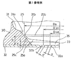
(第1参考例)
本発明の第1参考例として、燃料噴射ノズルをガソリン機関用燃料供給装置の燃料噴射弁に適用したものを図1、図2および図3に示す。
(First Reference Example)
As a first reference example of the present invention, a fuel injection nozzle applied to a fuel injection valve of a fuel supply device for a gasoline engine is shown in FIGS.
図3に示すように、強磁性材料からなる固定コア21は燃料噴射装置としての燃料噴射弁10の樹脂製のハウジングモールド11の内部に収容されている。磁性材料からなる可動コア22は筒状に形成されており、非磁性パイプ23および磁性パイプ24の内部空間に配設されている。可動コア22の外径は非磁性パイ
プ23の内径より僅かに小さく設定され、可動コア22は非磁性パイプ23に摺動可能に支持されている。可動コア22は、固定コア21と軸方向に対向し、固定コア21の下端面と所定の隙間を形成するように配設されている。
As shown in FIG. 3, the fixed
非磁性パイプ23は、固定コア21の可動コア側端部外周に嵌合し、レーザ溶接等により固定されている。非磁性パイプ23の反固定コア側端部には、磁性材料からなり段付きパイプ状に形成された磁性パイプ24が接続されている。なお、非磁性パイプ23の反固定コア側は可動コア22の案内部をなしている。図1に示すように、弁部材としてのニードル弁25の燃料噴射側の先端面25aは燃料流れに向かってその径が徐々に縮小するなだらかな円錐凸状に形成されており、当接部25bがバルブボディ30に設けられた弁座31bに円環状に着座可能である。ニードル弁25の他方の端部には図3に示すように接合部25dが形成されている。そして、接合部25dと可動コア22とがレーザ溶接され、ニードル弁25と可動コア22とが一体に連結される。接合部25dの外周には燃料通路としての二面取りが設けられている。
The
バルブボディ30は、スペーサ28を介して磁性パイプ24に挿入され、磁性パイプ24とレーザ溶接等により固定されている。スペーサ28の厚みは固定コア21と可動コア22とのエアギャップを所定値にするように調節される。
The
ステンレス製のオリフィスプレート32はカップ状に形成されており、ニードル弁25の燃料下流側でバルブボディ30の先端に溶接、例えば全周溶接により接合されている。
The stainless
スリーブ40は樹脂製であり、バルブボディ30およびオリフィスプレート32の外周に圧入され、オリフィスプレート32を保護している。オリフィスプレート32に形成されたオリフィス32a、32bから噴射される燃料はスリーブ40の開口部40aからエンジンに噴射される。
The
圧縮コイルスプリング26の一端は、可動コア22に設けられたスプリング座22aに当接し、圧縮コイルスプリング26の他端は、アジャスティングパイプ27の底部に当接している。圧縮コイルスプリング26は、可動コア22とニードル弁25とを図3の下方、つまり当接部25bがバルブボディ30の弁座31bに着座する方向に付勢している。
One end of the
アジャスティングパイプ27は固定コア21の内周に圧入されている。組付け時にアジャスティングパイプ27の圧入位置を調整することにより圧縮コイルスプリング26の付勢力を調整可能である。
The adjusting
電磁コイル50は樹脂製のスプール51の外周に巻回されており、スプール51は固定コア21、非磁性パイプ23、磁性パイプ24の外周に配設されている。電磁コイル50およびスプール51の外周にハウジングモールド11が樹脂成形され、ハウジングモールド11により電磁コイル50が包囲されている。図示しない電子制御装置によってターミナル52からリード線を介して電磁コイル50に励磁電流が流れると、ニードル弁25および可動コア22が圧縮コイルスプリング26の付勢力に抗して固定コア21の方向へ吸引され、当接部25bが弁座31bから離座する。
The
ターミナル52はハウジングモールド11に埋設されており、電磁コイル50に電気的に接続されている。ターミナル52は図示しない電子制御装置にワイヤハーネスを介して接続されている。
The terminal 52 is embedded in the
2枚の金属プレート61および62は上方の一端が固定コア21の外周に接し、下方の他端が磁性パイプ24の外周に接するように設けられ、電磁コイル50への通電時の磁束を通す磁路を形成する部材である。この2枚の金属プレート61、62により電磁コイル50が保護されている。
The two
フィルタ63は固定コア21の上方に配設されており、燃料タンクから燃料ポンプ等によって圧送され、燃料噴射弁10内に流入する燃料中のゴミ等の異物を除去する。固定コア21内にフィルタ63を通して流入した燃料は、アジャスティングパイプ27からニードル弁25の接合部25dに形成された二面取り部との隙間、さらには、バルブボディ30とニードル弁25との摺動部に形成された四面取り部との隙間を通過し、ニードル弁25の当接部25bと弁座31bとよりなる弁部に到る。図1に示すように、当接部25bが弁座31bから離座すると、当接部25bと弁座31bとが形成する開口部から燃料が燃料室35に流入する。
The
流体室としての燃料室35は、オリフィスプレート32の対向面33と、バルブボディ30の円錐斜面31aと、先端面25aとで仕切られ、略円板状に形成されている。
The
以下、ニードル弁25、バルブボディ30、オリフィスプレート32の構造を順次詳細に説明する。
Hereinafter, the structures of the
(1) ニードル弁25
図1に示すように、ニードル弁25の先端部は先端面25a、当接部25bおよび先端面25aと当接部25bとを連結する円環状曲面25cからなる。先端面25aは当接部25bの内周側に形成され、中心がニードル弁25の軸上に位置している。先端面25aとオリフィスプレート32の対向面33とのニードル開弁時におけるニードル弁の軸方向の距離hとオリフィスプレート32の後述するオリフィス32a、32bの径dとは、次式(1) を満たすように設定されている。
(1)
As shown in FIG. 1, the distal end portion of the
h<l.5d 、d<0.3(mm) ・・・(1)
とりわけ、d<0.25程度の小径オリフィスにして多数のオリフィスを設けることで噴射量を稼ぐようにするとよい。これは、所定流量の燃料が多数のオリフィスを通過するようにすることで、オリフィスから噴射される燃料が空気と接触する面積をより多くして、より微粒化を促進するためである。
h <l. 5d, d <0.3 (mm) (1)
In particular, it is preferable to increase the injection amount by providing a plurality of orifices with a small-diameter orifice of d <0.25. This is because by allowing a predetermined flow rate of fuel to pass through a large number of orifices, the area in which the fuel injected from the orifices comes into contact with air is increased, and atomization is further promoted.
またオリフィス径が小径のため、所定の面積のオリフィスプレートにおいてオリフィス間の燃料の通路を形成しやすい。このため、後述するようにニードル弁25のシート径をDS、各オリフィス間のピッチをDHとしたときのDS/DHの値を広い範囲に設定できる。より好ましくはd=0.15程度であるのがよい。
Further, since the orifice diameter is small, it is easy to form a fuel passage between the orifices in the orifice plate having a predetermined area. Therefore, as will be described later, the DS / DH value can be set in a wide range when the seat diameter of the
式(1)を満たすように距離hおよびオリフィス径dを設定するのは、バルブボディ30の円錐斜面31aからニードル弁25が離間したとき、当接部25bと円錐斜面31aとの隙間をオリフィスプレート32側に燃料が進み、オリフィスプレート32の対向面33に当たることで燃料室35に向けて曲げられ、対向面33に沿った燃料流れを形成するためである。この燃料流れは、直接オリフィスに向かう流れと、オリフィス間を通過する流れとに別れ、オリフィス間を通過した流れはオリフィスプレート中心で対向する流れによりUターンしてオリフィスに向かう流れとなる。これら互いに径方向の反対方向からオリフィスに向かう燃料流れがオリフィス直上で衝突しあい、不安定な流れ状態を作り燃料の微粒化を促進する。
The distance h and the orifice diameter d are set so as to satisfy the expression (1) when the
すなわち距離hと径dとが式(1)を満たすように設定されているので、先端面25aと対向面33との狭い隙間に燃料を流すことができ、対向面33に沿った燃料流れ同士の衝突を誘起することができる。これにより燃料同士の衝突のエネルギーを大きくして燃料の微粒化を促進することができる。
That is, since the distance h and the diameter d are set so as to satisfy the formula (1), the fuel can flow in a narrow gap between the tip surface 25a and the facing
(2) バルブボディ30
バルブボディ30の内径は先端付近からオリフィスプレート32に向かうにしたがい縮径しており、流体通路としての燃料通路を形成する内壁面31のオリフィスプレート32側に円錐斜面31aが形成されている。ニードル弁25の当接部25bは円錐斜面31aに形成された弁座31bに着座可能である。
(2)
The inner diameter of the
弁座31bと対向面33との間の垂直距離Hと、オリフィス32a、32bの径dとは次式(2) を満たすように設定されている。
The vertical distance H between the
H<4d ・・・(2)
すなわち燃料室35への燃料の入口である弁座31bがオリフィスプレート32に近く設定されている。
H <4d (2)
That is, a
燃料下流側に向けて円錐斜面31aを縮径させ、弁座31bと対向面33との間の垂直距離Hとオリフィス32a、32bの径dとを、式(2)を満たすように設定していることにより、ニードル弁25とバルブボディ30とが離間している場合、当接25bと弁座31bとの間から円錐斜面31aに治って燃料室35に流入する燃料を対向面33に沿わせることができる。
The
(3) オリフィスプレート32
噴霧の流れ方向を制御するオリフィスプレート32には、図2の(A)に示すようにオリフィスプレート32を板厚方向に貫通して径dの等しいオリフィス32a、32bが合計12個形成されている。図1に示すように、オリフィス32a、32bは、当接部25bの下流側の燃料主流の方向が対向面33と交差する位置を結んだ仮想包路線、図1では円錐斜面31aと対向面33との交線の内側に形成されている。
(3)
As shown in FIG. 2A, a total of twelve
図2の(A)に示すようにオリフィス32aおよび32bはそれぞれ同心円上に配置されており、オリフィス32aがオリフィス32bの内周側に位置している。さらに、各オリフィスの中心から同一半径で互いに接して円を確保できるように各オリフィスが配置されている。したがって、各オリフィスから噴射される噴霧がほぼ等しい領域を確保できるので、噴射先で噴霧が重複しにくい。
As shown in FIG. 2A, the
また、オリフィス32a、32bは、図2の(B)および(C)に示すようにオリフィスプレート32の燃料下流側に向けて中心軸から遠ざかるように傾斜しており、オリフィスプレート32の板厚方向に対するオリフィス32a、32bの傾斜角度をθ1 、θ2 とすると、θ1 、θ2 は次式(3) を満たしている。
Further, as shown in FIGS. 2B and 2C, the
θ1 <θ2 ・・・(3)
外周側のオリフィス32bの方が傾斜角度が大きいので、傾斜角度θ1、θ2を適切に設定すれば各オリフィス32a、32bから噴射される噴霧が互いに重なることなく均一に微粒化される。
θ1 <θ2 (3)
Since the
また、オリフィス32aの数をn1、オリフィス32bの数をn2とするとn1=n2である。オリフィスの数の配分を前述のように等しくし、中心から同一半径で互いに接して円を確保できるように各オリフィス32a、32bを配置すると、各オリフィスを通らずに線対称の軸を引くことができない。つまり、本参考例の配置によれば噴霧は一方向になる。
If the number of
図1に示すように、各オリフィス32a、32b間のピッチをDH0、DH1、ニードル弁25のシート径をDS とすると、DH0、DH1とDS とは次式(4) を満たしている。
As shown in FIG. 1, when the pitch between the
1.5<DS/DH0<6、1.5<DS/DH1<6・・・(4)
したがって、ニードル弁25とバルブボディ30とが離間している場合、当接部25bと弁座31bとの間から燃料室35へ流入する燃料は円錐斜面31aに沿って流れた後に、オリフィスに直接流入することなくオリフィスプレート32の対向面33により方向転換した後で対向面33と平坦面25aの間を所定距離進む。したがって燃料の主流が直接オリフィス32a、32bに流入することがなく燃料を効率的に微粒化できる。また、式(4)を満たすことにより、オリフィスプレート32の中心に近づき過ぎず、かつオリフィスプレート32の外周側に広がりすぎない範囲内にオリフィス32a、32bを配置できる。したがって、各オリフィス32a、32bに流入する燃料流れの強さを流入方向によらずほぼ均等にすることができる。これにより燃料の内部エネルギーを流れ同士の衝突による乱れという形で効率よく利用することができ、きわめて理想的な微粒化を実現できる。
1.5 <DS / DH0 <6, 1.5 <DS / DH1 <6 (4)
Therefore, when the
また、オリフィスの入口中央で均一な衝突を得ることができるのでオリフィスを形成する側壁全周の傾斜にそってきわめて方向性のいい噴霧を得ることができる。 Further, since a uniform collision can be obtained at the center of the inlet of the orifice, it is possible to obtain a spray with extremely good direction along the inclination of the entire circumference of the side wall forming the orifice.
図4はDS/DH、1.5d−h、4d−Hのそれぞれの値を横軸に、微粒化の度合いを縦軸にグラフに表したものである。オリフィス径d=0.15mmである。図4の(A)、(B)、(C)の測定結果は、式(1)、(2)、(4)の内、他の二つの式を満たす範囲で二式のパラメータを振らせ、その範囲内で残る一つの式のパラメータを振らせたものである。 FIG. 4 is a graph in which the values of DS / DH, 1.5d-h, and 4d-H are plotted on the horizontal axis, and the degree of atomization is plotted on the vertical axis. Orifice diameter d = 0.15 mm. The measurement results of (A), (B), and (C) in FIG. 4 are obtained by changing two parameters within a range that satisfies the other two equations of equations (1), (2), and (4). , The parameters of one expression remaining within the range are swung.
微粒化の度合いはSMD(Sauter Mean Diameter、ザウター平均粒径)で表し、1)図4(A)よりDS/DHの値が1.5〜6の範囲で、2)図4(B)より1.5d−hの値が0以上の範囲で、3)図4(C)より4d−H(mm)の値が0以上の範囲でSMDの値がそれぞれ100μm未満となり、良好な微粒化を実現できることがわかる。 The degree of atomization is represented by SMD (Sauter Mean Diameter, Sauter average particle diameter), 1) DS / DH values in the range of 1.5-6 from FIG. 4 (A), 2) From FIG. 4 (B). The value of 1.5 d-h is in the range of 0 or more, 3) From FIG. 4C, the value of 4d-H (mm) is in the range of 0 or more, the SMD value is less than 100 μm, respectively, and good atomization It can be seen that it can be realized.
燃料噴射弁10を吸気管に取り付けた状態を図5および図6に示す。図5および図6に示すエンジンは3気筒エンジンである。燃料噴射弁10は、吸気流れ下流側で各気筒に接続するインテークマニホールド2の各吸気分配管2a、2b、2cの集合部3よりも上流側、かつ図示しないスロットル弁よりも下流側の吸気管1に搭載されている。図5および図6に示す点線は燃料噴射弁10の噴霧範囲を示している。
A state in which the
本参考例の燃料噴射弁10は、図5および図6に示すように微粒化された燃料を広範囲に渡って噴射することができるので、一つの燃料噴射弁により各気筒に均等に、かつ均一に燃料を供給できる。したがって、各気筒毎に燃料噴射弁を取り付けるものに比べ、部品点数が少なく燃料噴射弁の制御も簡単化されるので製造コストが低減する。特に、小型エンジンに本実施例の燃料噴射弁10を搭載することが効果的である。
Since the
次に、燃料噴射弁10の作動について説明する。
Next, the operation of the
(1) 電磁コイル50への通電オフ時、可動コア22およびニードル弁25は圧縮コイルスプリング26の付勢力により図2の下方に付勢され、ニードル弁25の当接部25bが弁座31bに着座する。これにより、オリフィス32a、32bからの燃料噴射が遮断される。
(1) When energization of the
(2) 電磁コイル50への通電をオンすると、圧縮コイルスプリング26の付勢力に抗して可動コア22が固定コア21に吸引されるので、ニードル弁25の当接部25bが弁座31bから離座する。これにより、当接部25bと弁座31bとの開口部から燃料室35に燃料が流入する。燃料室35に流入した燃料は、燃料室35の中心部に向かう。中心部に向かう燃料は中央部で互いに衝突して径方向外側に向かう流れを生じ、この径方向外側に向かう燃料流れと中心部に向かう燃料流れとがオリフィス32a、32b上で衝突する。そして、微粒化された燃料がオリフィス32a、32bから噴射される。
(2) When energization of the
(変形例1)
図7に本参考例の変形例1を示す。
(Modification 1)
FIG. 7 shows a first modification of the present reference example.
オリフィス71、72は同心円上にそれぞれ4個、合計8個形成されており、オリフィス71はオリフィス72の内周側に位置している。前述した参考例と同量の燃料を噴射するために、各オリフィスの径は前述した参考例よりも大きくなっている。変形例1も、各オリフィスを通らずに線対称の軸を引くことができないので一方向噴射になる。
Four
変形例1でも前述した参考例と同様に、オリフィス71、72から噴射される燃料噴霧の微粒化が促進される。
In the first modification, atomization of the fuel spray injected from the
(変形例2)
図8に本参考例の変形例2を示す。
(Modification 2)
FIG. 8 shows a second modification of the present reference example.
オリフィス73、74は同心円上にそれぞれn1=4個、n2=8個の合計12個形成されており、オリフィス73はオリフィス74の内周側に位置している。各オリフィスの径は前述した参考例と同じである。変形例2では各オリフィスを通らずに線対称の軸を引くことができる。つまり、変形例2の配置によれば噴霧は二方向になる。
A total of 12
変形例2でも前述した参考例と同様に、オリフィス73、74から噴射される燃料噴霧の微粒化が促進される。
Also in the modified example 2, atomization of the fuel spray injected from the
(変形例3)
図9に本参考例の変形例3を示す。
(Modification 3)
FIG. 9 shows a third modification of the present reference example.
オリフィス75、76は同心円上にそれぞれn1=2個、n2=4個の合計6個形成されており、オリフィス75はオリフィス76の内周側に形成されている。前述した参考例と同量の燃料を噴射するために、各オリフィスの径は変形例1よりも大きくなっている。変形例3では各オリフィスを通らずに線対称の軸を引くことができる。つまり、変形例3の配置によれば噴霧は二方向になる。
A total of six
変形例3でも前述した参考例と同様に、オリフィス75、76から噴射される燃料噴霧の微粒化が促進される。
In the modified example 3, as in the reference example described above, atomization of the fuel spray injected from the
以上説明した本発明の第1参考例およびその変形例では、内周側および外周側のオリフィスの径を同じにしたが、内周側と外周側とで異なる値にしてもよい。
また、式(1)、(2)、(4)を満たしていれば、各オリフィスを中心として同一径の円を互いにほぼ接して確保できるようにオリフィスを配置しなくてもよい。また、各オリフィスを中心として同一径の円を互いにほぼ接して確保できるようにオリフィスを配置してあるなら、式(1)、(2)、(4)を満たしていなくてもよい。
In the first reference example of the present invention described above and the modification thereof, the diameters of the orifices on the inner peripheral side and the outer peripheral side are the same, but different values may be used on the inner peripheral side and the outer peripheral side.
In addition, as long as the expressions (1), (2), and (4) are satisfied, the orifices do not have to be arranged so that circles having the same diameter can be secured substantially in contact with each other. Further, if the orifices are arranged so that circles of the same diameter can be ensured almost in contact with each other at the center, the equations (1), (2), and (4) may not be satisfied.
(第2参考例)
本発明の第2参考例を図10に示す。
(Second reference example)
A second reference example of the present invention is shown in FIG.
ニードル弁80の先端部は、先端面80a、当接部80b、および先端面80aと当接部80bとを連結する円環状曲面80cからなる。当接部80bはバルブボディ81の内壁面としての円錐斜面82に設けた弁座82aに着座可能である。先端面80aは、当接部80bの内周側にオリフィスプレート83の対向面83aとほぼ平行、つまり面広がり方向において対向面83aとほぼ等間隔になるように平面状に形成されている。
The distal end portion of the
バルブボディ81の内径は先端付近からオリフィスプレート83に向かうにしたがい縮径しており、流体通路としての燃料通路を形成する内壁面のオリフィスプレート83側に円錐斜面82が形成されている。ニードル弁80の当接部80bは円錐斜面82に形成された弁座82aに着座可能である。
The inner diameter of the
オリフィスプレート83には、オリフィスプレート83を板厚方向に貫通して径dの等しいオリフィス84が合計4個形成されている。オリフィス84は、当接部80bの下流側の燃料主流の方向が対向面83aと交差する位置を結んだ仮想包路線、図10では円錐斜面82の仮想延長面と対向面83aとの交線の内側に形成されている。
The
ニードル開弁時における先端面80aと対向面83aとのニードル弁80の軸方向の距離hとオリフィスプレート83のオリフィス84の径dとは式(1) を満たすように設定されている。弁座82aと対向面83aとの間の垂直距離Hと、オリフィス84の径dとは式(2)を満たすように設定されている。
The distance h in the axial direction of the
また、オリフィス84は、燃料下流側に向かうにしたがいニードル弁80の中心軸から遠ざかるように傾斜している。ニードル弁80の中心軸に対するオリフィス84の傾斜角度をθとすると、θは次式(5)を満たしている。
The
15°≦θ(望ましくは20°≦θ) ・・・(5)
対向面83aにおける各オリフィス84のピッチをDH、ニードル弁80のシート径をDSとすると、DHとDSとは次式(6)を満たしている。
15 ° ≦ θ (desirably 20 ° ≦ θ) (5)
When the pitch of the
1.5<DS/DH<6 ・・・(6)
以上のような構成により、先端面80a、円錐斜面82および対向面83aで区画形成される流体室としての燃料室85に流入した燃料流れは各オリフィス84から直接噴射されることなくオリフィスプレート83に衝突した後に向きを変えてオリフィス直上で互いに衝突してから噴射されるので、第1参考例と同様にオリフィス84から噴射される燃料噴霧の微粒化が促進される。
1.5 <DS / DH <6 (6)
With the above-described configuration, the fuel flow that has flowed into the
(第1実施例)
本発明の第1実施例を図11に示す。尚、以下の実施例では、第1参考例、その各変形例、および第2参考例と同様の構成については説明を省略し、これらと異なる構成のみを説明する。
(First embodiment)
A first embodiment of the present invention is shown in FIG. In the following embodiments, the description of the same configurations as those of the first reference example, the modifications thereof, and the second reference example will be omitted, and only the configurations different from these will be described.
ニードル弁86の先端部は先端面86aおよび当接部86bからなる。先端面86aは、当接部86bの内周側に燃料下流側に突出する凸球面状に形成されている。当接部86bは弁座82aに着座可能である。
The distal end portion of the
オリフィスプレート87は、予めオリフィス88を形成した平板部材を例えば先端が球面状のポンチでプレスして凹ませることにより形成される。オリフィスプレート87の対向面87aは、先端面86aの形状に合わせ先端面86aとのの間隔がほぼ等しくなるように凹球面状に形成されている。ここで対向面87aは、ニードル弁86が弁座82aから離座したときに流入する燃料にオリフィスプレート87が晒される範囲内の面を表す。さらに先端面86aと対向面87aとの間隔がほぼ等しいとは、先端面86aおよび対向面87aに降ろした共通垂線の長さが任意のニードル弁リフト位置における面広がり方向においてほぼ等しいことを表す。オリフィスプレート87には、オリフィスプレート87を板厚方向に貫通して径dの等しいオリフィス88が合計4個形成されている。オリフィス88は、当接部86bの下流側の燃料主流の方向が対向面87aと交差する位置を結んだ仮想包路線、図11では円錐斜面82の仮想延長面と対向面87aとの交線の内側に形成されている。
The
ニードル開弁時における先端面86aと対向面87aとの距離hとオリフィス88の径dとは式(1)を満たすように設定されている。ここで距離hは、ニードル開弁時に先端面86aおよび対向面87aに降ろした最短の共通垂線の長さを表す。弁座82aから対向面87aの外周縁を通りニードル弁86の中心軸と直交する仮想平面までの垂直距離Hと、オリフィス88の径dとは式(2)を満たすように設定されている。
The distance h between the
また、オリフィス88は燃料下流側に向かうにしたがいニードル弁86の中心軸から遠ざかるように傾斜しており、ニードル弁86の中心軸に対するオリフィス88の傾斜角度をθとすると、θは式(5)を満たしている。
対向面87aにおける各オリフィス88のピッチをDH、ニードル弁86のシート径をDSとすると、DHとDSとは式(6)を満たしている。
Further, the
When the pitch of the
第1実施例では、ニードル弁86の先端形状に合わせてオリフィスプレート87を燃料下流側に凹ませているので、予めオリフィスを形成した平板部材を凹ませる際に、ニードル弁86の中心軸からオリフィス88がさらに遠ざかる。これにより、平板状のオリフィスプレートでは加工が困難な傾斜角度の大きいオリフィスであっても、ニードル弁の先端面の形状に合わせてオリフィスプレートを凹ませることによりニードル弁の中心軸に対するオリフィスの傾斜角度を容易に拡大し、燃料噴霧角度を拡大することができる。したがって、吸気弁に近づけて極力ノズル直下の噴霧を燃焼室に噴射するために大きな噴霧角度を必要とする燃料噴射弁を容易に製造できる。
In the first embodiment, since the
さらに、先端面86a、円錐斜面82および対向面87aで区画形成される流体室としての燃料室89に流入した燃料流れは各オリフィス88から直接噴射されることなくオリフィスプレート87に衝突した後に向きを変えてオリフィス直上で互いに衝突してから噴射されるので、第1参考例と同様にオリフィス88から噴射される燃料噴霧の微粒化が促進される。
Further, the fuel flow that has flowed into the
(第2実施例)
本発明の第2実施例を図12に示す。
(Second embodiment)
A second embodiment of the present invention is shown in FIG.
ニードル弁90の先端部は先端面90aおよび当接部90bからなる。先端面90aは、当接部90bの内周側に燃料下流側に突出する凸円錐状に形成されている。当接部90bは弁座82aに着座可能である。
The distal end portion of the
オリフィスプレート91は、予めオリフィス92を形成した平板部材を例えば先端が円錐状のポンチでプレスして凹ませることにより形成される。オリフィスプレート91の対向面91aは、先端面90aの形状に合わせ先端面90aとの間隔がほぼ等しくなるように凹円錐状に形成されている。ここで対向面91aは、ニードル弁90が弁座82aから離座したときに流入する燃料に晒される範囲内の面を表す。さらに先端面90aと対向面91aとの間隔がほぼ等しいとは、先端面90aおよび対向面91aに降ろした共通垂線の長さが任意のニードル弁90のリフト位置における面広がり方向においてほぼ等しいことを表す。オリフィスプレート91には、オリフィスプレート91を板厚方向に貫通して径dの等しいオリフィス92が合計4個形成されている。オリフィス92は、当接部90bの下流側の燃料主流の方向が対向面91aと交差する位置を結んだ仮想包路線、図12では円錐斜面82の仮想延長面と対向面91aとの交線の内側に形成されている。
The
ニードル開弁時における先端面90aと対向面91aとの距離hとオリフィス92の径dとは式(1)を満たすように設定されている。ここで距離hは、ニードル開弁時に先端面90aおよび対向面91aに降ろした最短の共通垂線の長さを表す。弁座82aから対向面91aの外周縁を通りニードル弁90の中心軸と直交する仮想平面までの垂直距離Hと、オリフィス92の径dとは式(2)を満たすように設定されている。
The distance h between the
また、オリフィス92は燃料下流側に向かうにしたがいニードル弁90の中心軸から遠ざかるように傾斜しており、ニードル弁90の中心軸に対するオリフィス92の傾斜角度をθとすると、θは式(5)を満たしている。対向面91aにおける各オリフィス92のピッチをDH、ニードル弁90のシート径をDSとすると、DHとDSとは式(6)を満たしている。
Further, the
第2実施例でも、第1実施例と同様にニードル弁90の先端形状に合わせてオリフィスプレート91を燃料下流側に凹ませているので、ニードル弁の中心軸に対するオリフィスの傾斜角度を容易に拡大し、燃料噴霧角度を拡大することができる。したがって、大きな噴霧角度を必要とする燃料噴射弁を容易に製造できる。
Also in the second embodiment, the
さらに、先端面90a、円錐斜面82および対向面91aで区画形成される流体室としての燃料室93に流入した燃料流れは各オリフィス92から直接噴射されることなくオリフィスプレート91に衝突した後に向きを変えてオリフィス直上で互いに衝突してから噴射されるので、第1実施例と同様にオリフィス92から噴射される燃料噴霧の微粒化が促進される。
Further, the fuel flow that has flowed into the
以上説明した上記各実施例では、ニードル弁とバルブボディとが離間している場合、全周からオリフィスプレートの中央に向かって流れた燃料の一部はオリフィスプレートの中央部において方向を変えられ、Uターンして各オリフィスに向かう。このオリフィスプレートの中央部からUターンする燃料流れは、オリフィスプレート外周からオリフィスヘ流入する流れとオリフィス入口の中央で互いに衝突する。 In each of the embodiments described above, when the needle valve and the valve body are separated from each other, a part of the fuel that has flowed from the entire circumference toward the center of the orifice plate can be changed in direction at the center of the orifice plate. Make a U-turn toward each orifice. The fuel flow that makes a U-turn from the center of the orifice plate collides with the flow that flows from the outer periphery of the orifice plate into the orifice and the center of the orifice inlet.
オリフィスプレート中央でUターンした後にオリフィスヘ流入する流れの強さはオリフィスプレート外周からオリフィスヘ流入する流れとほぼ同じ強さのためオリフィス周囲に渦の生じない均等な衝突を得ることができより効率的な微粒化ができる。同時にオリフィスの入口中央で燃料が衝突し、しかも均一な衝突が得られるので微粒化した燃料はオリフィスにより方向性が良好に制御される。 The strength of the flow that flows into the orifice after making a U-turn in the center of the orifice plate is almost the same as the flow that flows into the orifice from the periphery of the orifice plate, so that it is possible to obtain a uniform collision with no vortex around the orifice. Atomization is possible. At the same time, the fuel collides at the center of the inlet of the orifice, and a uniform collision can be obtained. Therefore, the directionality of the atomized fuel is well controlled by the orifice.
このようにオリフィスから噴射される燃料噴霧の微粒化が促進されることにより、燃料噴霧が広範囲に渡って空気と混合しやすく燃料の燃焼効率が増大するので、排気ガス中に排出される有害物質および燃料消費量を低減することができる。 By promoting atomization of the fuel spray injected from the orifice in this way, the fuel spray is easily mixed with air over a wide range, and the combustion efficiency of the fuel is increased. Therefore, harmful substances discharged into the exhaust gas In addition, fuel consumption can be reduced.
10 燃料噴射弁
21 固定コア
22 可動コア
25、80、86、90 ニードル弁(弁部材)
25a、80a、86a、90a 先端面
25b、80b、86b、90b 当接部
30、81 ノズルボディ
31 内壁面
31a、82 円錐斜面
31b、82a 弁座
32、83、87、91 オリフィスプレート
32a、32b、71、72、73、74、75、76、84、88、92 オリフィス
33、83a、87a、91a 対向面
35、85、89、93 燃料室(流体室)
10
25a, 80a, 86a,
Claims (8)
前記弁座に環状に着座可能な当接部を有し、前記当接部が前記弁座から離座ならびに着座することにより前記流体通路を開閉する弁部材と、
固定コアと、
前記固定コアの外周に配設されるスプールと、
前記スプールの外周に巻回される電磁コイルと、
前記固定コアと軸方向で対向するよう配設されると共に、前記弁部材と一体に連結され、前記電磁コイルに励磁電流が流れると、前記固定コアの方向へ吸引される可動コアと、
前記弁部材よりも流体下流側の前記バルブボディに設けられるオリフィスプレートであって、板厚方向に貫通する複数のオリフィスを有するオリフィスプレートとを備えたガソリン機関用燃料供給装置の燃料噴射ノズルであって、
前記オリフィスプレートの前記弁部材との対向面と、前記弁部材の下流側先端部において前記当接部の内周側に形成される先端面と、前記内壁面とで略円盤状の流体室を形成し、
前記内壁面は、その仮想延長線が前記オリフィスプレートの対向面と交差する円錐斜面を有しており、
前記オリフィスは、前記仮想延長線と前記オリフィスプレートの対向面との交線の内側に形成されており、
前記弁部材の先端面は、前記当接部の内周側に燃料下流側に突出する凸球面状または凸円錐状に形成されており、
前記オリフィスプレートを燃料下流側に凹ませ、前記バルブボディの先端に接合しており、
前記内壁面に沿って前記流体室に流入した燃料が前記オリフィスプレートに衝突し、前記オリフィスから噴射され、
前記オリフィスは、二重同心円上に配置されており、内周側オリフィスと前記オリフィスプレートの中心軸とを結ぶ線が外周側オリフィスと周方向でずれていることを特徴とする燃料噴射ノズル。 A valve body provided with a valve seat on the inner wall surface forming the fluid passage;
A valve member that opens and closes the fluid passage when the contact portion is separated from and seated on the valve seat ;
A fixed core;
A spool disposed on the outer periphery of the fixed core;
An electromagnetic coil wound around the outer periphery of the spool;
A movable core that is disposed so as to face the fixed core in the axial direction, is integrally connected to the valve member, and is attracted in the direction of the fixed core when an excitation current flows through the electromagnetic coil;
A fuel injection nozzle for a fuel supply device for a gasoline engine , comprising an orifice plate provided in the valve body on the fluid downstream side of the valve member, the orifice plate having a plurality of orifices penetrating in the plate thickness direction. hand,
A substantially disk-shaped fluid chamber is formed by a surface of the orifice plate facing the valve member, a distal end surface formed on the inner peripheral side of the contact portion at a downstream distal end portion of the valve member, and the inner wall surface. Forming,
The inner wall surface has a conical slope whose virtual extension line intersects the opposing surface of the orifice plate,
The orifice is formed inside an intersection line between the virtual extension line and the facing surface of the orifice plate,
The front end surface of the valve member is formed in a convex spherical shape or a convex conical shape protruding toward the fuel downstream side on the inner peripheral side of the contact portion,
The orifice plate is recessed to the fuel downstream side and joined to the tip of the valve body,
The fuel that has flowed into the fluid chamber along the inner wall surface collides with the orifice plate, and is injected from the orifice.
The orifice is arranged on a double concentric circle, and a line connecting the inner circumference side orifice and the central axis of the orifice plate is shifted in the circumferential direction from the outer circumference side orifice .
前記弁座に環状に着座可能な当接部を有し、前記当接部が前記弁座から離座ならびに着座することにより前記流体通路を開閉する弁部材と、
固定コアと、
前記固定コアの外周に配設されるスプールと、
前記スプールの外周に巻回される電磁コイルと、
前記固定コアと軸方向で対向するよう配設されると共に、前記弁部材と一体に連結され、前記電磁コイルに励磁電流が流れると、前記固定コアの方向へ吸引される可動コアと、
前記弁部材よりも流体下流側の前記バルブボディに設けられるオリフィスプレートであって、板厚方向に貫通する複数のオリフィスを有するオリフィスプレートとを備えたガソリン機関用燃料供給装置の燃料噴射ノズルであって、
前記オリフィスプレートの前記弁部材との対向面と、前記弁部材の下流側先端部において前記当接部の内周側に形成される先端面と、前記内壁面とで略円盤状の流体室を形成し、
前記弁部材の先端面は、前記当接部の内周側に燃料下流側に突出する凸球面状または凸円錐状に形成されており、
前記オリフィスプレートを燃料下流側に凹ませ、前記バルブボディの先端に接合しており、
前記オリフィスは、二重同心円上に配置されており、内周側オリフィスと前記オリフィスプレートの中心軸とを結ぶ線が外周側オリフィスと周方向でずれていることを特徴とする燃料噴射ノズル。 A valve body provided with a valve seat on the inner wall surface forming the fluid passage;
A valve member that opens and closes the fluid passage when the contact portion is separated from and seated on the valve seat ;
A fixed core;
A spool disposed on the outer periphery of the fixed core;
An electromagnetic coil wound around the outer periphery of the spool;
A movable core that is disposed so as to face the fixed core in the axial direction, is integrally connected to the valve member, and is attracted in the direction of the fixed core when an excitation current flows through the electromagnetic coil;
A fuel injection nozzle for a fuel supply device for a gasoline engine , comprising an orifice plate provided in the valve body on the fluid downstream side of the valve member, the orifice plate having a plurality of orifices penetrating in the plate thickness direction. hand,
A substantially disk-shaped fluid chamber is formed by a surface of the orifice plate facing the valve member, a distal end surface formed on the inner peripheral side of the contact portion at a downstream distal end portion of the valve member, and the inner wall surface. Forming,
The front end surface of the valve member is formed in a convex spherical shape or a convex conical shape protruding toward the fuel downstream side on the inner peripheral side of the contact portion,
The orifice plate is recessed on the fuel downstream side and joined to the tip of the valve body,
The orifice is arranged on a double concentric circle, and a line connecting the inner circumference side orifice and the central axis of the orifice plate is shifted in the circumferential direction from the outer circumference side orifice .
Priority Applications (1)
| Application Number | Priority Date | Filing Date | Title |
|---|---|---|---|
| JP2003305202A JP3726830B2 (en) | 1996-10-25 | 2003-08-28 | Fuel injection nozzle and fuel supply device |
Applications Claiming Priority (3)
| Application Number | Priority Date | Filing Date | Title |
|---|---|---|---|
| JP28379196 | 1996-10-25 | ||
| JP17816197 | 1997-07-03 | ||
| JP2003305202A JP3726830B2 (en) | 1996-10-25 | 2003-08-28 | Fuel injection nozzle and fuel supply device |
Related Parent Applications (1)
| Application Number | Title | Priority Date | Filing Date |
|---|---|---|---|
| JP24509197A Division JP3750768B2 (en) | 1996-10-25 | 1997-09-10 | Fluid injection nozzle |
Publications (3)
| Publication Number | Publication Date |
|---|---|
| JP2004003518A JP2004003518A (en) | 2004-01-08 |
| JP2004003518A5 JP2004003518A5 (en) | 2005-05-26 |
| JP3726830B2 true JP3726830B2 (en) | 2005-12-14 |
Family
ID=30448944
Family Applications (1)
| Application Number | Title | Priority Date | Filing Date |
|---|---|---|---|
| JP2003305202A Expired - Lifetime JP3726830B2 (en) | 1996-10-25 | 2003-08-28 | Fuel injection nozzle and fuel supply device |
Country Status (1)
| Country | Link |
|---|---|
| JP (1) | JP3726830B2 (en) |
Families Citing this family (7)
| Publication number | Priority date | Publication date | Assignee | Title |
|---|---|---|---|---|
| KR100719462B1 (en) | 2006-06-16 | 2007-05-18 | 주식회사 케피코 | Injector for vehicle |
| JP4906466B2 (en) | 2006-10-16 | 2012-03-28 | 日立オートモティブシステムズ株式会社 | Fuel injection valve and fuel injection device for internal combustion engine equipped with the same |
| CN101589222B (en) * | 2007-01-29 | 2012-05-09 | 三菱电机株式会社 | Fuel injection valve |
| JP5161853B2 (en) * | 2009-09-29 | 2013-03-13 | 三菱電機株式会社 | Fuel injection valve |
| JP2014066186A (en) * | 2012-09-26 | 2014-04-17 | Hitachi Automotive Systems Ltd | Fuel injection valve |
| JP2016169739A (en) * | 2016-05-23 | 2016-09-23 | 株式会社デンソー | Fuel injection device |
| JP2024064824A (en) * | 2022-10-28 | 2024-05-14 | 株式会社日立製作所 | Liquid jet device |
-
2003
- 2003-08-28 JP JP2003305202A patent/JP3726830B2/en not_active Expired - Lifetime
Also Published As
| Publication number | Publication date |
|---|---|
| JP2004003518A (en) | 2004-01-08 |
Similar Documents
| Publication | Publication Date | Title |
|---|---|---|
| JP3750768B2 (en) | Fluid injection nozzle | |
| JP3183156B2 (en) | Fluid injection nozzle | |
| EP1581739B1 (en) | Spray pattern control with non-angled orifices formed on dimpled fuel injection metering disc having a sac volume reducer | |
| US7448560B2 (en) | Unitary fluidic flow controller orifice disc for fuel injector | |
| US6405946B1 (en) | Fluid injection nozzle | |
| US6769625B2 (en) | Spray pattern control with non-angled orifices in fuel injection metering disc | |
| US6966505B2 (en) | Spray control with non-angled orifices in fuel injection metering disc and methods | |
| US6929197B2 (en) | Generally circular spray pattern control with non-angled orifices in fuel injection metering disc and method | |
| JP2001317431A (en) | Fluid injection nozzle | |
| US6845930B2 (en) | Spray pattern and spray distribution control with non-angled orifices in fuel injection metering disc and methods | |
| JPH11200998A (en) | Fluid injection nozzle | |
| JP3726830B2 (en) | Fuel injection nozzle and fuel supply device | |
| US6820826B2 (en) | Spray targeting to an arcuate sector with non-angled orifices in fuel injection metering disc and method | |
| JP3377004B2 (en) | Fluid injection nozzle | |
| KR100419183B1 (en) | Fluid injection nozzle | |
| JP3130439B2 (en) | Fluid injection nozzle | |
| JP3707143B2 (en) | Fluid injection nozzle | |
| JPH08232811A (en) | Fluid injection nozzle | |
| JP3129188B2 (en) | Fuel injection device for internal combustion engine | |
| JPH1193807A (en) | Fluid injection nozzle | |
| JP5818856B2 (en) | Fuel injection valve |
Legal Events
| Date | Code | Title | Description |
|---|---|---|---|
| A521 | Written amendment |
Free format text: JAPANESE INTERMEDIATE CODE: A523 Effective date: 20040817 |
|
| A871 | Explanation of circumstances concerning accelerated examination |
Free format text: JAPANESE INTERMEDIATE CODE: A871 Effective date: 20040817 |
|
| A975 | Report on accelerated examination |
Free format text: JAPANESE INTERMEDIATE CODE: A971005 Effective date: 20040924 |
|
| A977 | Report on retrieval |
Free format text: JAPANESE INTERMEDIATE CODE: A971007 Effective date: 20050107 |
|
| A131 | Notification of reasons for refusal |
Free format text: JAPANESE INTERMEDIATE CODE: A131 Effective date: 20050125 |
|
| A521 | Written amendment |
Free format text: JAPANESE INTERMEDIATE CODE: A523 Effective date: 20050316 |
|
| A131 | Notification of reasons for refusal |
Free format text: JAPANESE INTERMEDIATE CODE: A131 Effective date: 20050531 |
|
| A521 | Written amendment |
Free format text: JAPANESE INTERMEDIATE CODE: A523 Effective date: 20050728 |
|
| TRDD | Decision of grant or rejection written | ||
| A01 | Written decision to grant a patent or to grant a registration (utility model) |
Free format text: JAPANESE INTERMEDIATE CODE: A01 Effective date: 20050906 |
|
| A61 | First payment of annual fees (during grant procedure) |
Free format text: JAPANESE INTERMEDIATE CODE: A61 Effective date: 20050919 |
|
| R150 | Certificate of patent or registration of utility model |
Free format text: JAPANESE INTERMEDIATE CODE: R150 |
|
| FPAY | Renewal fee payment (event date is renewal date of database) |
Free format text: PAYMENT UNTIL: 20081007 Year of fee payment: 3 |
|
| FPAY | Renewal fee payment (event date is renewal date of database) |
Free format text: PAYMENT UNTIL: 20091007 Year of fee payment: 4 |
|
| FPAY | Renewal fee payment (event date is renewal date of database) |
Free format text: PAYMENT UNTIL: 20101007 Year of fee payment: 5 |
|
| FPAY | Renewal fee payment (event date is renewal date of database) |
Free format text: PAYMENT UNTIL: 20101007 Year of fee payment: 5 |
|
| FPAY | Renewal fee payment (event date is renewal date of database) |
Free format text: PAYMENT UNTIL: 20111007 Year of fee payment: 6 |
|
| FPAY | Renewal fee payment (event date is renewal date of database) |
Free format text: PAYMENT UNTIL: 20121007 Year of fee payment: 7 |
|
| FPAY | Renewal fee payment (event date is renewal date of database) |
Free format text: PAYMENT UNTIL: 20121007 Year of fee payment: 7 |
|
| FPAY | Renewal fee payment (event date is renewal date of database) |
Free format text: PAYMENT UNTIL: 20131007 Year of fee payment: 8 |
|
| R250 | Receipt of annual fees |
Free format text: JAPANESE INTERMEDIATE CODE: R250 |
|
| R250 | Receipt of annual fees |
Free format text: JAPANESE INTERMEDIATE CODE: R250 |
|
| R250 | Receipt of annual fees |
Free format text: JAPANESE INTERMEDIATE CODE: R250 |
|
| EXPY | Cancellation because of completion of term |