WO2020250507A1 - 自動分析装置、および異常検知方法 - Google Patents
自動分析装置、および異常検知方法 Download PDFInfo
- Publication number
- WO2020250507A1 WO2020250507A1 PCT/JP2020/008937 JP2020008937W WO2020250507A1 WO 2020250507 A1 WO2020250507 A1 WO 2020250507A1 JP 2020008937 W JP2020008937 W JP 2020008937W WO 2020250507 A1 WO2020250507 A1 WO 2020250507A1
- Authority
- WO
- WIPO (PCT)
- Prior art keywords
- reagent
- concentration
- reagent container
- measured
- sample
- Prior art date
- Legal status (The legal status is an assumption and is not a legal conclusion. Google has not performed a legal analysis and makes no representation as to the accuracy of the status listed.)
- Ceased
Links
Images







Classifications
-
- G—PHYSICS
- G01—MEASURING; TESTING
- G01N—INVESTIGATING OR ANALYSING MATERIALS BY DETERMINING THEIR CHEMICAL OR PHYSICAL PROPERTIES
- G01N35/00—Automatic analysis not limited to methods or materials provided for in any single one of groups G01N1/00 - G01N33/00; Handling materials therefor
- G01N35/00584—Control arrangements for automatic analysers
- G01N35/00594—Quality control, including calibration or testing of components of the analyser
- G01N35/00613—Quality control
- G01N35/00663—Quality control of consumables
-
- G—PHYSICS
- G01—MEASURING; TESTING
- G01N—INVESTIGATING OR ANALYSING MATERIALS BY DETERMINING THEIR CHEMICAL OR PHYSICAL PROPERTIES
- G01N35/00—Automatic analysis not limited to methods or materials provided for in any single one of groups G01N1/00 - G01N33/00; Handling materials therefor
- G01N35/10—Devices for transferring samples or any liquids to, in, or from, the analysis apparatus, e.g. suction devices, injection devices
- G01N35/1002—Reagent dispensers
-
- G—PHYSICS
- G01—MEASURING; TESTING
- G01N—INVESTIGATING OR ANALYSING MATERIALS BY DETERMINING THEIR CHEMICAL OR PHYSICAL PROPERTIES
- G01N35/00—Automatic analysis not limited to methods or materials provided for in any single one of groups G01N1/00 - G01N33/00; Handling materials therefor
- G01N35/00584—Control arrangements for automatic analysers
- G01N35/00594—Quality control, including calibration or testing of components of the analyser
- G01N35/00613—Quality control
- G01N35/00663—Quality control of consumables
- G01N2035/00673—Quality control of consumables of reagents
-
- G—PHYSICS
- G01—MEASURING; TESTING
- G01N—INVESTIGATING OR ANALYSING MATERIALS BY DETERMINING THEIR CHEMICAL OR PHYSICAL PROPERTIES
- G01N35/00—Automatic analysis not limited to methods or materials provided for in any single one of groups G01N1/00 - G01N33/00; Handling materials therefor
- G01N35/00584—Control arrangements for automatic analysers
- G01N35/00722—Communications; Identification
- G01N2035/00891—Displaying information to the operator
-
- G—PHYSICS
- G01—MEASURING; TESTING
- G01N—INVESTIGATING OR ANALYSING MATERIALS BY DETERMINING THEIR CHEMICAL OR PHYSICAL PROPERTIES
- G01N35/00—Automatic analysis not limited to methods or materials provided for in any single one of groups G01N1/00 - G01N33/00; Handling materials therefor
- G01N35/02—Automatic analysis not limited to methods or materials provided for in any single one of groups G01N1/00 - G01N33/00; Handling materials therefor using a plurality of sample containers moved by a conveyor system past one or more treatment or analysis stations
- G01N35/04—Details of the conveyor system
- G01N2035/0474—Details of actuating means for conveyors or pipettes
- G01N2035/0491—Position sensing, encoding; closed-loop control
- G01N2035/0494—Detecting or compensating piositioning errors
-
- G—PHYSICS
- G01—MEASURING; TESTING
- G01N—INVESTIGATING OR ANALYSING MATERIALS BY DETERMINING THEIR CHEMICAL OR PHYSICAL PROPERTIES
- G01N35/00—Automatic analysis not limited to methods or materials provided for in any single one of groups G01N1/00 - G01N33/00; Handling materials therefor
- G01N35/10—Devices for transferring samples or any liquids to, in, or from, the analysis apparatus, e.g. suction devices, injection devices
- G01N35/1009—Characterised by arrangements for controlling the aspiration or dispense of liquids
- G01N35/1016—Control of the volume dispensed or introduced
- G01N2035/1018—Detecting inhomogeneities, e.g. foam, bubbles, clots
Definitions
- This disclosure relates to an automatic analyzer and an abnormality detection method.
- an automatic analyzer that analyzes biological samples such as blood and urine
- analysis is performed using different reagents for each analysis item.
- a fixed amount of each of these reagents is stored in a reagent container for each type of reagent, and is usually mounted in a reagent storage of an automatic analyzer.
- quality control is performed to confirm that the analysis performance of the device is normal.
- quality control quality control substances (control samples) are measured at regular time intervals or fixed number of sample intervals between measurements of patient samples, and whether the measurement results are within the control range associated with the control samples or within the day. Fluctuations and daily fluctuations are examined to determine whether the accuracy is within the range.
- the operator investigates the cause from the condition of the automatic analyzer, reagents, and sample. There are various factors such as dirt on the automatic analyzer, bubbles in the reagent container, and bubbles on the sample.
- the operator determines that something is wrong with the reagent container, the operator needs to discharge the reagent container from the automatic analyzer and inspect the container.
- a technique for detecting the cause of some trouble generated in the reagent container for example, there is bubble detection in the reagent container.
- a technique for detecting bubbles in the reagent container there is a method of detecting bubbles from a change in the height of the liquid level (see, for example, Patent Document 1). Further, there are a method of detecting bubbles from the amount of movement of the reagent probe during dispensing and a method of recording the transition of the liquid level from the first dispensing (for the latter, see, for example, Patent Document 2).
- the present disclosure proposes a technique for facilitating the operator's work of investigating the cause of a defect.
- the present disclosure discloses a reagent dispensing unit that sucks a reagent from a reagent container that stores a reagent and discharges the reagent into a reaction container that contains a reaction solution containing a sample, a sample type, and a sample.
- a storage unit that is determined for each type of sample and stores concentration-related information related to the concentration of the measurement target component contained in the sample, and a detection unit that detects the measurement concentration that is the concentration of the measurement target component contained in the reaction solution.
- the operator can easily perform the work of investigating the cause of the defect in the automatic analyzer.
- a block diagram showing the overall configuration of the automatic analyzer The figure which shows the configuration example of the analysis module.
- FIG. 5 is a diagram showing a configuration example of a foam reagent discharge setting screen 900 for setting whether or not to automatically discharge the reagent container when it is determined that “foam is generated” in the target reagent container.
- embodiment of the present disclosure may be implemented by software running on a general-purpose computer, or may be implemented by dedicated hardware or a combination of software and hardware.
- each information of the present disclosure will be described in a "table” format, but these information do not necessarily have to be represented by a data structure by a table, and a data structure such as a list, a DB, a queue, and others. It may be expressed by. Therefore, “table”, “list”, “DB”, “queue”, etc. may be simply referred to as "information" to indicate that they do not depend on the data structure.
- FIG. 1 is a system block diagram showing an overall configuration example of the automatic analyzer 1.
- the automatic analyzer 1 includes a computer 10 for overall management and an analysis module 20.
- the overall management computer 10 includes components of an ordinary computer, and includes, for example, a processor, a memory and a storage device, a communication device, a display device (display unit), an input device, and the like.
- the determination unit 11 in FIG. 1 is composed of a processor
- the storage unit 12 is composed of a memory and a storage device. The determination unit 11 determines the possibility of bubble generation, and the storage unit 12 stores information on the measured concentration received from the analysis module 20 (contents of the tables of FIGS. 4 to 6 described later).
- the analysis module 20 sucks the detection unit 21 for detecting the measured concentration, the moving unit 22 for moving the reagent container, and the reagent contained in the reagent container, and generates a reaction solution composed of the reagent and the sample. It is provided with a reagent dispensing unit 23 for discharging the reagent into the reaction vessel, and an abnormality detecting unit 24 for detecting an abnormality in the analysis module.
- the abnormality detection unit 24 is provided inside, for example, the analysis module 20, includes a sample bubble detection camera 218 (see FIG. 2), and also various sensors for detecting various abnormalities in the mechanism operation, information processing abnormalities, and the like. It can be configured with various software that detects abnormalities in the analysis results.
- FIG. 2 is a diagram showing an overall configuration example of the analysis module 20.
- the analysis module 20 reacts with the transfer rack 201, the sample dispensing nozzle 203, the incubator (reaction disk) 204, the sample dispensing chip and the reaction vessel transfer mechanism 206, the sample dispensing chip and the reaction vessel holding member 207.
- a sample container 202 for holding a sample is erected in the transfer rack 201 of the analysis module 20, and the sample container 202 is moved to the sample dispensing position near the sample dispensing nozzle 203 by the rack transfer line 216.
- a sample foam detection camera 218 is provided above the rack transfer line 216. The sample bubble detection camera 218 confirms the presence or absence of bubbles in the sample, and if there are bubbles, notifies the overall management computer 10 as an abnormality.
- a plurality of reaction vessels 205 can be installed in the incubator 204, and rotational movements for moving each of the reaction vessels 205 installed in the circumferential direction to a predetermined position are possible.
- the sample dispensing chip and the reaction vessel transport mechanism 206 can be moved in three directions of the X-axis, the Y-axis, and the Z-axis, and the sample dispensing chip and the reaction vessel holding member 207, the reaction vessel stirring mechanism 208, and the sample dispensing chip Then, the sample dispensing chip and the reaction vessel are transported by moving within a predetermined range of the reaction vessel disposal hole 209, the sample dispensing chip mounting position 210, and the incubator 204.
- a plurality of unused reaction vessels and sample dispensing tips are installed on the sample dispensing tip and the reaction vessel holding member 207.
- the sample dispensing tip and reaction vessel transfer mechanism 206 moves above the sample dispensing tip and reaction vessel holding member 207, descends to grip an unused reaction vessel, and then rises, and further, a predetermined position of the incubator 204. Move upwards and descend to install the reaction vessel.
- the sample dispensing tip and reaction vessel transfer mechanism 206 then move above the sample dispensing tip and reaction vessel holding member 207, descend to grip the unused sample dispensing tip, and then rise to sample. Move above the tip mounting position 210 and descend to place the sample dispensing tip there.
- the sample dispensing nozzle 203 can be rotated and moved up and down, and after rotating and moving above the sample dispensing tip mounting position 210, it descends and press-fits the sample dispensing tip into the tip of the sample dispensing nozzle 203. And attach it.
- the sample dispensing nozzle 203 equipped with the sample dispensing tip moves above the sample container 202 placed on the transport rack 201 and then lowers to suck a predetermined amount of the sample held in the sample container 202.
- the sample dispensing nozzle 203 that has sucked the sample moves above the incubator 204 and then descends to discharge the sample into the unused reaction vessel 205 held in the incubator 204.
- the sample dispensing nozzle 203 moves above the sample dispensing tip and the reaction vessel disposal hole 209, and the used sample dispensing tip is discarded from the disposal hole.
- a plurality of reagent containers 217 are installed on the reagent disk (reagent installation mechanism) 211.
- a reagent disc cover 212 is provided on the upper part of the reagent disc 211, and the inside of the reagent disc 211 is kept at a predetermined temperature.
- An opening (reagent disc cover opening) may be provided in a part of the reagent disc cover 212.
- the reagent dispensing nozzle 213 can rotate and move up and down, and after rotating and moving above the opening of the reagent disk cover 212, descends to immerse the tip of the reagent dispensing nozzle 213 in the reagent in a predetermined reagent container. Then, a predetermined amount of reagent is sucked.
- the reagent dispensing nozzle 213 detects the liquid level of the liquid in the reagent container and lowers the nozzle at a position where the tip of the nozzle reaches slightly below the liquid level in order to reduce the amount of liquid adhering to the outer wall of the nozzle. Stop and aspirate a predetermined amount of reagent. After rising, the reagent dispensing nozzle 213 rotates and moves above the predetermined position of the incubator 204 to discharge the reagent into the reaction vessel 205.
- the reaction vessel 205 holding the discharged sample and the reagent moves to a predetermined position by the rotation of the incubator 204, and is conveyed to the reaction vessel stirring mechanism 208 by the sample dispensing tip and the reaction vessel transfer mechanism 206.
- the reaction vessel stirring mechanism 208 stirs and mixes the sample and the reagent in the reaction vessel by applying a rotary motion to the reaction vessel.
- the reaction vessel after stirring is returned to a predetermined position in the incubator 204 by the sample dispensing tip and the reaction vessel transfer mechanism 206.
- the reaction solution suction nozzle 214 can be rotated and moved up and down, the sample and the reagent are dispensed, the stirring is completed, and the reaction solution suction nozzle 214 moves above the reaction vessel 205 after a predetermined reaction time has passed in the incubator 204 and descends.
- the reaction solution in the reaction vessel 205 is sucked.
- the reaction liquid sucked by the reaction liquid suction nozzle 214 is analyzed by the detection unit 215.
- the reaction vessel 205 sucked in the reaction solution is moved to a predetermined position by the rotation of the incubator 204, and is moved from the incubator 204 to the sample dispensing tip and above the reaction vessel waste hole 209 by the sample dispensing tip and the reaction vessel transport mechanism 206. Move and dispose of from the disposal hole.
- FIG. 3 is a diagram showing an overall configuration example of the moving unit 22.
- the moving unit 22 constitutes a part of the analysis module 20, and includes a rotary reagent setting mechanism (reagent disk) 211, a reagent dispensing nozzle 213, a reagent stirring mechanism (magnetic particle stirring mechanism) 219, and a reagent loader 220. And the reagent information reading mechanism 221.
- a plurality of reagent containers 217 are installed in the reagent installation mechanism 211 and the reagent loader 220. In the reagent container 217, for example, a set of three liquid reagents necessary for measuring one test item is set. One of them is a reagent containing magnetic particles.
- the reagent information reading mechanism 221 is installed adjacent to the reagent loader 220. Reagent information is given to the reagent container 217, and the reagent information on the reagent loader 220 can be acquired by using the reagent information reading mechanism 221.
- the operator installs the reagent container 217 at a predetermined position on the reagent loader 220 and carries in the reagent. Further, the operator operates the reagent loader 220 using the overall management computer 10 and discharges the reagent container 217 to the reagent discharge preparation position of the reagent loader 220. Normally, the reagent loader 220 is refrigerated.
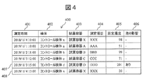
- FIG. 4 is a diagram showing a configuration example of a measurement concentration data table 400 that stores the concentration measured by the detection unit 21 of the analysis module 20.
- the measurement concentration data table 400 includes a measurement time 401, a sample 402 indicating the type of control sample measured, information 403 of the reagent container used in the measurement, measurement item 404, measurement concentration 405, and the influence of bubbles 406. , Is included as a component item.
- a measurement time 401 a sample 402 indicating the type of control sample measured
- information 403 of the reagent container used in the measurement e.g., information 403 of the reagent container used in the measurement
- measurement item 404 e.g., measurement concentration 405
- the influence of bubbles 406. Is included as a component item.
- “Yes" is stored when the determination unit 11 determines that there is an influence of bubbles.
- the measurement concentration data 407 shows that the measurement concentration was 201 when the measurement item DDD was measured using the reagent in the reagent container D for the control sample d, which was affected by bubbles.
- FIG. 5 is a diagram showing a configuration example of a control sample allocation data table 500 that stores information assigned to each control sample.
- the control sample allocation information table 500 measures the control sample 501 indicating the type of the control sample, the measurement item 502, the known concentration 503 indicating the correct concentration of the corresponding control sample, and the allowable lower limit value 504 of the measured concentration.
- the permissible upper limit value 505 of the concentration obtained is included as a component item.
- a quality control process is executed in which each control sample is measured at predetermined intervals (for example, once a day) to confirm the measurement accuracy of the apparatus.
- the measurement item AAA of the “control sample a” is measured, the allowable lower limit value 504 is set to “35” and the allowable upper limit value 505 is set to “65”. Therefore, if the measured concentration of the control sample a is within the range of 35 or more and 65 or less, it is determined that the operation of the analysis module 20 is normal, and if it is not satisfied, it is determined that there is some problem.
- FIG. 6 shows warnings (hereinafter, alarms) of various abnormalities of the device detected by the abnormality detection unit 24 (see FIG. 1).
- alarms warnings
- FIG. 6 shows the configuration example of the warning data table 600 which stores the occurrence warning of the bubble detected by the determination part 11.
- the warning data table 600 includes an alarm occurrence date and time 601, an alarm code 602, and an alarm content 603 as constituent items.
- alarms there are various types of alarms, such as abnormalities in information processing, abnormalities in mechanical operation, and abnormalities in analysis results.
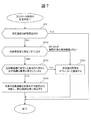
- FIG. 7 is a flowchart for explaining the details of the quality control process of the analysis module 20 by the determination unit 11.
- the quality control process can be executed by the determination unit 11 at the timing when the measurement of one item of one control sample is completed, for example.
- the determination unit 11 determines the possibility of foam generation in the reagent container based on the information of the measurement concentration data table 400, the control sample allocation information table 500, and the warning data table 600 stored in the storage unit 12. ..
- the accuracy control process is performed by taking as an example a case where the measurement of the measurement item "XXX" of the "control sample X" using the "reagent container X" is completed and the information 408 is stored in the measurement concentration data table 400. Will be described.
- the determination unit 11 corresponding to the processor is the main operator of each step.
- the process of each step or the process of a plurality of steps is modularized and the corresponding module is used. It may be the main body of operation.
- the presence or absence of bubbles generated in the reagent container is described here as an example of the abnormality in the reagent container, deterioration of the reagent can also be regarded as an abnormality in the reagent container.
- Step 701 The determination unit 11 acquires the measurement concentration "20" of the "control sample X" measurement item "XXX” from the measurement concentration 405 of the measurement concentration data table 400. Then, the determination unit 11 confirms whether or not the acquired measured concentration (concentration value 20) is within the permissible range defined by the permissible lower limit value 504 and the permissible upper limit value 505 of the control sample allocation information table 500. If the measured concentration is within the permissible range (YES in step 701), it is determined that there is no abnormality, and the quality control process ends. On the other hand, if the measured concentration is out of the permissible range (NO in step 701), the process proceeds to step 702.
- the determination unit 11 will execute step 702.
- Step 702 In order to confirm that there is no problem in the detection unit 21, the determination unit 11 determines whether the measurement concentration of the control sample using the reagent container other than the “reagent container X” is normal, that is, the measurement concentration of each control sample is the control sample. It is confirmed whether or not it is within the allowable range set in the allocation information table 500. At this time, the control sample in which the influence of bubbles 406 is “Yes” in the measurement concentration data table 400 is excluded from the confirmation target. In this case, it is a problem of the reagent container, not a problem of the detection unit 21.
- the user sets the range of the period to be confirmed (for example, whether to confirm the measured concentration up to 1 day before or to confirm the measured concentration up to 2 days ago) using the confirmation range setting screen 800 of FIG. can do.
- FIG. 8 shows an example in which the operator has set to confirm the measured concentration up to 2 days ago.
- step 702 When it is determined that the measured concentration of the control sample using another reagent container (for example, a reagent container other than "reagent container X”) is normal (YES in step 702), the process proceeds to step 703.
- the process proceeds to step 705. Further, even if there is no measurement result to be confirmed, the process proceeds to step 705.
- the process proceeds to step 703. By executing the processes of step 702 and step 703, it is confirmed that no abnormality has occurred other than the reagent container X.
- the determination unit 11 refers to the warning data table 600 and confirms whether or not an abnormality has occurred in the analysis module 20 from the date and time when the measurement can be performed normally.
- the alarm for detecting bubbles in the reagent container shall be excluded from the confirmation target. If the alarm that a bubble was detected in a specific reagent container is set as the confirmation target, it cannot be distinguished from other abnormalities (for example, an abnormality of the device itself such as a sensor abnormality), and the process shifts to step 705 even when bubbles are generated. Because it will be done. In other words, in the case of bubble generation, it is necessary to detect it separately from the problem for other reasons.
- step 703 If it is determined that an abnormality has occurred in the analysis module 20 from the date and time when the measurement can be performed normally (YES in step 703), the process proceeds to step 705. When it is determined that no abnormality has occurred in the analysis module 20 from the date and time when the measurement can be performed normally (NO in step 703), the process proceeds to step 704.
- the determination unit 11 determines that no abnormality has occurred in the analysis module 20 from the date and time that can be measured from these, and shifts the process to step 704.
- Step 704 The determination unit 11 determines that there is no problem with the analysis module 20 and that bubbles may be generated in the target reagent container, and discharges the reagent container to the discharge preparation position. That is, in the case of the above example, the determination unit 11 determines that there is no abnormality in the analysis module 20 and there is a possibility of foam generation in the “reagent container X”, and the reagent container X is placed in the discharge preparation position (refrigerated). Discharge to the reagent loader 220). Further, the determination unit 11 stores the information of "with bubbles" in the influence 406 of bubbles in the measurement concentration data table 400 for the measurement result determined that there is a possibility of bubbles.
- Step 705 If there is an abnormality at another measured concentration, there is a possibility that the abnormality has occurred due to a factor other than the generation of bubbles in the reagent container X. Therefore, the determination unit 11 notifies the operator of the abnormality of the measured value (measured concentration). For the notification, a method using an alarm display on the screen of the display unit may be used, or a method using an alarm sound such as a buzzer may be used.
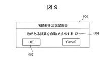
- FIG. 9 is a diagram showing a configuration example of a foam reagent discharge setting screen 900 for setting whether or not to automatically discharge the reagent container when it is determined that the target reagent container has “foam generation”. Is.
- the reagent container determined to have "foam generation” can be automatically discharged. That is, when the determination unit 11 determines that the target reagent container has “foam generation”, the determination unit 11 automatically discharges the reagent container in response to the check item box 901 being checked.
- the determination unit 11 displays the screen illustrated in FIG. 10 described later on the display screen and waits for the operator's instruction input.
- FIG. 10 is a diagram showing a configuration example of the foam reagent discharge selection screen 1000 for inquiring the operator whether to discharge the reagent container determined to have “foam generation”.
- the foam reagent discharge selection screen 1000 is a screen displayed when the check item box 901 is not checked at the timing when the possibility of foam generation is detected in the target reagent container by the determination unit 11. Is.
- the reagent container determined by the determination unit 11 to be “possible to generate bubbles” is discharged.
- the Cancel button 1002 the reagent container determined by the determination unit 11 to be "possible to generate bubbles” is not discharged and remains held on the reagent disk 211.
- FIG. 11 is a diagram showing a configuration example of a cause threshold table 1100 in a reagent container that stores a reagent deterioration threshold and a foam threshold assigned to each control sample and a set of measurement items.
- the reagent container in-threshold threshold table 1100 includes a control sample 1101 indicating the type of control sample, a measurement item 1102, a reagent deterioration threshold 1103 for identifying whether the cause of the measurement concentration abnormality is reagent deterioration, and a measurement concentration abnormality.
- a bubble presence threshold 1104 for identifying whether the cause is bubble generation and a valid previous measurement value 1105 are included as constituent items.
- the cause of the abnormality in the measured concentration is determined by whether the difference between the measured concentration of the previous time and the current measurement exceeds the threshold of the reagent deterioration threshold 1103 and the threshold with bubbles 1104.
- the determination unit 11 determines that there is a possibility of both reagent deterioration and bubbles, assuming that there is no sufficient difference to distinguish them.
- the reagent deterioration threshold 1103 of the measurement item "AAA" of "control sample a” is set to "previous measurement value ⁇ 25"
- the threshold with bubbles is set to "previous measurement value ⁇ 30". Therefore, if -25 ⁇ (current measurement concentration-previous measurement concentration) ⁇ 25, it is judged that there is a possibility of both reagent deterioration and bubbles, assuming that there is no sufficient difference to distinguish them. If -30 ⁇ (current measurement concentration-previous measurement concentration) ⁇ -25 or 25 ⁇ (current measurement concentration-previous measurement concentration) ⁇ 30, it is determined that the reagent may be deteriorated. If -30> (current measurement concentration-previous measurement concentration) or 30 ⁇ (current measurement concentration-previous measurement concentration), it is determined that bubbles are generated in the reagent container.
- the influence of the measured concentration is larger in the generation of bubbles than in the deterioration of the reagent, and the threshold of deterioration of the reagent 1103 is included in the threshold of 1104 with bubbles.
- the reagent deteriorates severely due to exposure of the reagent to room temperature for a long time, the influence of the reagent deterioration on the measured concentration becomes larger than the generation of bubbles, and this nesting relationship may be broken. Therefore, a valid previous measurement value of 1105 is set. Measurements beyond the period of valid previous measurements 1105 are not used as the nesting may be broken.
- FIG. 12 is a flowchart illustrating the details of the process for determining whether the reagent container determined to have an abnormality is due to bubbles in the reagent container or due to reagent deterioration.
- the possibility of foam generation and the possibility of reagent deterioration in the reagent container are determined based on the information of the measurement concentration data table 400 and the cause threshold table 1100 in the reagent container stored in the storage unit 12. ..
- Step 1201 The determination unit 11 determines whether the measurement concentration of the same measurement item of the same sample exists in the past. Since the past measured values are used to distinguish between reagent deterioration and foam generation, if they do not exist, it is impossible to distinguish between foam and reagent deterioration, and the process proceeds to step 1207. If it exists, the process proceeds to step 1202.
- the determination unit 11 determines whether the measurement item "xxx" has been measured in the past by the "control sample x". First, the determination unit 11 acquires a valid previous measurement value 1105 “up to 12 hours ago” of the measurement item “xxx” of the “control sample x” from the cause threshold table 1100 in the reagent container. Therefore, the determination unit 11 acquires the past measured values in the range from 13:00 on January 4, 2019, which is the current measurement date and time, to 12 hours before. Since there is a measured concentration "98" corresponding to 10:00 on January 4, 2019 in the measured concentration data table 400, the process proceeds to step 1202. If there is no past measured concentration, the threshold value cannot be obtained, so the process proceeds to step 1207.
- Step 1202 The determination unit 11 acquires a threshold value for distinguishing between reagent deterioration and bubble generation from the cause threshold value table 1100 in the reagent container. If there is no combination of the corresponding control sample and the measurement item in the cause threshold table 1100 in the reagent container, the threshold cannot be obtained and the process proceeds to step 1207 because it is impossible to distinguish between bubbles and reagent deterioration.
- the reagent deterioration threshold 1103 and the bubble-bearing threshold 1104 of the measurement item "xxx" of the "control sample x" are acquired from the reagent container cause threshold table 1100. Since the reagent deterioration threshold 1103 of the measurement item "xxx” of the "control sample x" can be obtained as the previous value of ⁇ 15 and the threshold value of 1104 with bubbles as the previous value of ⁇ 20, the process proceeds to step 1203.
- Step 1203 The determination unit 11 determines whether the reagent deterioration and bubbles can be distinguished from the measured values this time.
- the reagent deterioration threshold value 1103 is not exceeded, that is, when the difference between the measured concentrations of this time and the previous time does not exceed the reagent deterioration threshold value, it is assumed that there is no difference in the measured concentrations so that the reagent deterioration and the bubbles can be distinguished, and the process proceeds to step 1207. If the threshold of reagent deterioration is exceeded, the measurement proceeds to step 1204, assuming that the measured concentrations are so different that the reagent deterioration and bubbles can be distinguished.
- the measured concentration this time is "20" and the measured concentration last time is “98". Since the difference between the measured concentrations of this time and the previous measurement exceeds "-78" and the reagent deterioration threshold value 1103 "-15", it is assumed that there is a difference in the measured concentrations so that the reagent deterioration and bubbles can be distinguished, and the process proceeds to step 1204.
- Step 1204 From the threshold value acquired in step 1202, the determination unit 11 determines whether the abnormality of the measured concentration this time is due to reagent deterioration or bubble generation. If the difference between the measured concentrations of this time and the previous time exceeds the reagent deterioration threshold 1103 and does not exceed the foam generation threshold 1104, it is determined that there is a possibility of reagent deterioration, and the process proceeds to step 1205. If the difference between the measured concentrations of this time and the previous time exceeds the threshold value of foam generation 1104, it is determined that there is a possibility of foam generation in the reagent container, and the process proceeds to step 1206.
- Step 1205 When it is determined in step 1204 that there is a possibility of reagent deterioration, the determination unit 11 notifies the operator of the possibility of reagent deterioration.
- Step 1206 When it is determined in step 1204 that there is a possibility of foam generation in the reagent container, the determination unit 11 notifies the operator of the possibility of foam generation.
- the operator is notified of the possibility of reagent deterioration or foam generation. It should be noted that the operator may be notified of whether the threshold value has not been registered or whether a large difference has occurred by notifying the step progressed.
- the notifications in steps 1205, 1206, and 1207 may be notified by an alarm display on the screen of the display unit, or by an alarm sound such as a buzzer.
- Step 1208 The determination unit 11 determines that there is no problem with the analysis module 20 and that there is a problem with the target reagent container, and discharges the reagent container to the discharge preparation position.
- FIG. 13 is a diagram showing a configuration example of a liquid level table 1300 in a reagent container that holds the liquid level in each reagent container.
- the reagent container internal liquid level table 1300 includes the reagent container 1301 and the current reagent liquid level 1302 of the reagent container as constituent items.
- the liquid level height 1302 is obtained from the amount of descent of the reagent dispensing nozzle 213 when the reagent is sucked, the amount of suction at that time, and the bottle size.
- the generation of bubbles can be detected. For example, when the liquid level of bubbles is detected during reagent suction, the amount of drop of the reagent dispensing nozzle 213 is small, and the calculated liquid level height is higher than the previous liquid level height. At this time, it can be determined that bubbles are generated.
- the disappearance of bubbles can be detected. For example, if the previous liquid level height is calculated with bubbles and the bubbles disappear during the current reagent dispensing, the liquid level height will be lower than expected.
- the threshold value of the change in the liquid level for identifying the generation or disappearance of bubbles may be set by the operator from the overall management computer 10, or the product designer may set a fixed value in the storage unit 12 in advance. May be good.
- FIG. 14 is a flowchart illustrating a process that combines a mechanism for detecting bubbles from a change in the reagent liquid level and a mechanism for determining reagent deterioration from a reagent deterioration threshold.
- the possibility of foam generation or disappearance in the reagent container, the reagent Judge the possibility of deterioration.
- Step 1401 The determination unit 11 calculates the liquid level height from the amount of the reagent dispensing nozzle 213 lowered by the reagent suction this time and the shape of the reagent bottle.
- the calculated liquid level height is compared with the previous liquid level height 1302 recorded in the reagent container internal liquid level height table 1300. As a result of the comparison, if the liquid level height calculated this time is larger than the liquid level height calculated last time, it is determined that bubbles may be generated, and the process proceeds to step 1402. If the liquid level height calculated this time is smaller than the liquid level height calculated last time, it is determined that there is a possibility of bubbles disappearing, and the process proceeds to step 1403. If there is no difference between the liquid level calculated this time and the liquid level calculated last time, it is determined that there is no possibility of bubble generation or bubble disappearance, and the process proceeds to step 1404.
- the threshold value of the change in the liquid level for identifying the generation of bubbles is set to "2 mm” and the threshold value for the change in the liquid level for identifying the disappearance of bubbles is set to "-4 mm", this time. If the calculated liquid level height of "Reagent Container X" is larger than “2 mm” than the previous liquid level height, it is judged that bubbles are generated, and if it is smaller than "-4 mm", it is judged that it disappears, and "-4 mm or more and 2 mm or less”. If it is, it is judged that bubbles are generated and bubbles do not disappear.
- Step 1402 When it is determined in step 1401 that there is a possibility of foam generation, the determination unit 11 notifies the operator of the possibility of reagent deterioration, and proceeds to step 1407.
- Step 1403 When it is determined in step 1401 that there is a possibility of bubble disappearance, the determination unit 11 notifies the operator of the possibility of bubble disappearance, and proceeds to step 1407.
- the operator may be notified of the previous measurement results using the reagent container.
- Step 1404 When the determination unit 11 determines in step 1401 that there is no possibility of bubble generation or bubble disappearance, the determination unit 11 confirms whether the difference between the measured concentrations of the previous time and the current measurement concentration exceeds the threshold value of reagent deterioration. If the reagent deterioration threshold is exceeded, the process proceeds to step 1405. If it is smaller than the reagent deterioration threshold value, it is assumed that it cannot be determined whether the measurement concentration abnormality is due to bubbles or reagent deterioration at the set threshold value, and the process proceeds to step 1406.
- Step 1405 When the determination unit 11 determines in step 1404 that there is a possibility of reagent deterioration, the determination unit 11 notifies the operator of the possibility of reagent deterioration in the target reagent container.
- Step 1406 the determination unit 11 determines that when the difference between the measured concentration of the previous time and the current measurement concentration is smaller than the threshold value of reagent deterioration, it could not determine whether the abnormality of the measured concentration is due to bubbles or reagent deterioration. Notify to.
- Step 1407 The determination unit 11 determines that there is no problem with the analysis module 20 and that there is a problem with the target reagent container, and discharges the reagent container to the discharge preparation position.
- step 1402, step 1403, step 1405, and step 1406 may be notified by an alarm display on the screen of the display unit, or by an alarm sound such as a buzzer.
- concentration-related information determined for each type of sample for example, various control samples
- the type of sample and related to the concentration of the component to be measured contained in the sample Based on the concentration of the component to be measured contained in the reaction solution (by comparing the two pieces of information), the occurrence of anomalies in the reagent container (generation of bubbles in the reagent container and inclusion in the reagent container). Judge the presence or absence of deterioration of the reagent itself. In this way, when the measurement result of quality control becomes abnormal, it is possible to make it easier for the operator to investigate the cause by detecting whether there is a problem with the reagent and automatically discharging the problematic reagent. It becomes.
- the concentration-related information indicates the permissible range of the concentration of the component to be measured, which is determined to determine the presence or absence of bubbles in the reagent container. Then, the determination unit (processor) determines whether or not bubbles are generated in the reagent container and whether or not the reagent is deteriorated, based on the comparison result of whether or not the measured concentration is within the permissible range.
- the possibility of abnormality of the reagent can be detected only by determining whether the measured concentration is within an appropriate range. That is, it is possible to detect the possibility of abnormality in the reagent by a relatively simple process.
- the judgment unit responds to the instruction (instruction of automatic discharge by the operator or instruction of discharge each time) and puts the reagent container in the discharge preparation position (the reagent container is refrigerated).
- the moving part is controlled so as to move to the position where it is set). In this way, by discharging the reagent container determined to be abnormal to the refrigerated position, the deterioration of the reagent due to temperature changes is eliminated, and the operator can check the discharged reagent container at any time. become able to.
- the abnormality is the generation of bubbles in the reagent container, it is possible to reduce the concern about fraudulent results due to bubbles and improve the reliability of the measurement results by discharging the reagent container that is likely to be bubbles. it can.
- the present invention can determine the cause of the abnormality in the reagent container in more detail by combining with the detection of bubbles due to the change in the reagent liquid level in the reagent container.
- the function of the embodiment can also be realized by the program code of the software.
- a storage medium in which the program code is recorded is provided to the system or device, and the computer (or CPU or MPU) of the system or device reads out the program code stored in the storage medium.
- the program code itself read from the storage medium realizes the function of the above-described embodiment, and the program code itself and the storage medium storing the program code itself constitute the present disclosure.
- Storage media for supplying such program codes include, for example, flexible disks, CD-ROMs, DVD-ROMs, hard disks, optical disks, magneto-optical disks, CD-Rs, magnetic tapes, non-volatile memory cards, and ROMs. Etc. are used.
- the OS operating system
- the processing enables the functions of the above-described embodiment to be realized. You may. Further, after the program code read from the storage medium is written in the memory on the computer, the CPU of the computer or the like performs a part or all of the actual processing based on the instruction of the program code, and the processing is performed. May realize the functions of the above-described embodiment.
- the program code of the software that realizes the function of the embodiment via the network, it is distributed as a storage means such as a hard disk or a memory of the system or a device or a storage medium such as a CD-RW or a CD-R.
- the computer (or CPU or MPU) of the system or device may read and execute the program code stored in the storage means or the storage medium at the time of use.
- Various inventions can be formed by an appropriate combination of a plurality of components disclosed in the present embodiment. For example, some components may be deleted from all the components shown in the present embodiment. In addition, components across different embodiments may be combined as appropriate.
- the techniques of the present disclosure have been described in the context of specific embodiments, but these are for illustration purposes and not to limit the techniques of the present disclosure. Those skilled in the art will find that there are numerous combinations of hardware, software, and firmware suitable for implementing the techniques disclosed.
- the described software can be implemented in a wide range of programs or scripting languages such as assembler, C / C ++, perl, Shell, PHP, Java®.
- control lines and information lines are shown as necessary for explanation, and not all control lines and information lines are necessarily shown in the product. All configurations may be interconnected.
Landscapes
- Physics & Mathematics (AREA)
- Health & Medical Sciences (AREA)
- Life Sciences & Earth Sciences (AREA)
- Chemical & Material Sciences (AREA)
- Analytical Chemistry (AREA)
- Biochemistry (AREA)
- General Health & Medical Sciences (AREA)
- General Physics & Mathematics (AREA)
- Immunology (AREA)
- Pathology (AREA)
- Engineering & Computer Science (AREA)
- Quality & Reliability (AREA)
- Automatic Analysis And Handling Materials Therefor (AREA)
Priority Applications (4)
| Application Number | Priority Date | Filing Date | Title |
|---|---|---|---|
| JP2021525913A JP7270039B2 (ja) | 2019-06-11 | 2020-03-03 | 自動分析装置、および異常検知方法 |
| US17/596,014 US12163972B2 (en) | 2019-06-11 | 2020-03-03 | Automated analysis device, and abnormality detecting method |
| CN202080040309.7A CN113950626B (zh) | 2019-06-11 | 2020-03-03 | 自动分析装置以及异常检测方法 |
| EP20823579.6A EP3985398B1 (en) | 2019-06-11 | 2020-03-03 | Automated analysis device, and abnormality detecting method |
Applications Claiming Priority (2)
| Application Number | Priority Date | Filing Date | Title |
|---|---|---|---|
| JP2019-109032 | 2019-06-11 | ||
| JP2019109032 | 2019-06-11 |
Publications (1)
| Publication Number | Publication Date |
|---|---|
| WO2020250507A1 true WO2020250507A1 (ja) | 2020-12-17 |
Family
ID=73782160
Family Applications (1)
| Application Number | Title | Priority Date | Filing Date |
|---|---|---|---|
| PCT/JP2020/008937 Ceased WO2020250507A1 (ja) | 2019-06-11 | 2020-03-03 | 自動分析装置、および異常検知方法 |
Country Status (5)
| Country | Link |
|---|---|
| US (1) | US12163972B2 (https=) |
| EP (1) | EP3985398B1 (https=) |
| JP (1) | JP7270039B2 (https=) |
| CN (1) | CN113950626B (https=) |
| WO (1) | WO2020250507A1 (https=) |
Cited By (1)
| Publication number | Priority date | Publication date | Assignee | Title |
|---|---|---|---|---|
| EP4459260A4 (en) * | 2021-12-31 | 2025-06-25 | Shenzhen Mindray Animal Medical Technology Co., Ltd. | DEVICE AND METHOD FOR SAMPLE ANALYSIS |
Citations (4)
| Publication number | Priority date | Publication date | Assignee | Title |
|---|---|---|---|---|
| JP2004170279A (ja) | 2002-11-21 | 2004-06-17 | Hitachi High-Technologies Corp | 自動分析装置 |
| JP2007303937A (ja) | 2006-05-10 | 2007-11-22 | Olympus Corp | 自動分析装置 |
| JP2013217741A (ja) * | 2012-04-06 | 2013-10-24 | Hitachi High-Technologies Corp | 自動分析装置 |
| JP2016057228A (ja) * | 2014-09-11 | 2016-04-21 | 日本電子株式会社 | 自動分析装置及び異常判定方法 |
Family Cites Families (17)
| Publication number | Priority date | Publication date | Assignee | Title |
|---|---|---|---|---|
| JPH0815265A (ja) * | 1994-06-30 | 1996-01-19 | Shimadzu Corp | 自動化学分析装置 |
| JP3866446B2 (ja) * | 1999-05-07 | 2007-01-10 | 株式会社東芝 | 自動分析装置 |
| JP2001124788A (ja) * | 1999-10-25 | 2001-05-11 | Hitachi Ltd | 自動分析装置 |
| JP4991586B2 (ja) * | 2008-01-31 | 2012-08-01 | 株式会社日立ハイテクノロジーズ | 自動分析装置 |
| GB0806771D0 (en) * | 2008-04-12 | 2008-05-14 | Spd Swiss Prec Diagnostics Gmb | Assay devices comprising bubble-forming means |
| JP5618489B2 (ja) * | 2009-02-17 | 2014-11-05 | シスメックス株式会社 | 分析装置、分析方法及びコンピュータプログラム |
| JP5331551B2 (ja) | 2009-04-16 | 2013-10-30 | 株式会社日立ハイテクノロジーズ | 分析装置 |
| JP5274436B2 (ja) * | 2009-11-26 | 2013-08-28 | ベックマン コールター, インコーポレイテッド | 自動分析装置 |
| JP5216051B2 (ja) * | 2010-06-23 | 2013-06-19 | 株式会社日立ハイテクノロジーズ | 自動分析装置および自動分析方法 |
| JP5562421B2 (ja) * | 2010-07-14 | 2014-07-30 | 株式会社日立ハイテクノロジーズ | 自動分析装置、分析方法及び情報処理装置 |
| JP5897323B2 (ja) * | 2011-12-26 | 2016-03-30 | 株式会社日立ハイテクノロジーズ | 自動分析装置および測定値異常検出方法 |
| JP6013796B2 (ja) * | 2012-06-25 | 2016-10-25 | 株式会社日立ハイテクノロジーズ | 自動分析装置及び試料測定方法 |
| US10768189B2 (en) * | 2014-01-27 | 2020-09-08 | Hitachi High-Tech Corporation | Automatic analysis apparatus |
| EP3252476B1 (en) * | 2015-01-28 | 2024-10-30 | Hitachi High-Tech Corporation | Liquid surface inspection device, automated analysis device, and processing device |
| JP6649942B2 (ja) * | 2015-02-23 | 2020-02-19 | 株式会社日立ハイテクノロジーズ | 自動分析装置 |
| JP6466752B2 (ja) * | 2015-03-19 | 2019-02-06 | 株式会社日立ハイテクノロジーズ | 自動分析装置及び自動分析方法並びに自動分析システム |
| CN108780102B (zh) * | 2016-03-25 | 2022-05-17 | 株式会社日立高新技术 | 自动分析装置 |
-
2020
- 2020-03-03 EP EP20823579.6A patent/EP3985398B1/en active Active
- 2020-03-03 JP JP2021525913A patent/JP7270039B2/ja active Active
- 2020-03-03 WO PCT/JP2020/008937 patent/WO2020250507A1/ja not_active Ceased
- 2020-03-03 US US17/596,014 patent/US12163972B2/en active Active
- 2020-03-03 CN CN202080040309.7A patent/CN113950626B/zh active Active
Patent Citations (4)
| Publication number | Priority date | Publication date | Assignee | Title |
|---|---|---|---|---|
| JP2004170279A (ja) | 2002-11-21 | 2004-06-17 | Hitachi High-Technologies Corp | 自動分析装置 |
| JP2007303937A (ja) | 2006-05-10 | 2007-11-22 | Olympus Corp | 自動分析装置 |
| JP2013217741A (ja) * | 2012-04-06 | 2013-10-24 | Hitachi High-Technologies Corp | 自動分析装置 |
| JP2016057228A (ja) * | 2014-09-11 | 2016-04-21 | 日本電子株式会社 | 自動分析装置及び異常判定方法 |
Non-Patent Citations (1)
| Title |
|---|
| See also references of EP3985398A4 |
Cited By (1)
| Publication number | Priority date | Publication date | Assignee | Title |
|---|---|---|---|---|
| EP4459260A4 (en) * | 2021-12-31 | 2025-06-25 | Shenzhen Mindray Animal Medical Technology Co., Ltd. | DEVICE AND METHOD FOR SAMPLE ANALYSIS |
Also Published As
| Publication number | Publication date |
|---|---|
| JP7270039B2 (ja) | 2023-05-09 |
| EP3985398A4 (en) | 2023-05-10 |
| EP3985398A1 (en) | 2022-04-20 |
| US20220221477A1 (en) | 2022-07-14 |
| EP3985398B1 (en) | 2024-07-10 |
| JPWO2020250507A1 (https=) | 2020-12-17 |
| US12163972B2 (en) | 2024-12-10 |
| CN113950626A (zh) | 2022-01-18 |
| CN113950626B (zh) | 2025-06-13 |
Similar Documents
| Publication | Publication Date | Title |
|---|---|---|
| JP5517467B2 (ja) | 自動分析装置 | |
| JP4966913B2 (ja) | 液体分注装置 | |
| CN113777338B (zh) | 自动分析装置以及自动分析方法 | |
| JP7182614B2 (ja) | 自動分析装置 | |
| US20100001876A1 (en) | Analyzer and analysis method | |
| JP5331056B2 (ja) | 自動分析装置 | |
| JP2004170279A (ja) | 自動分析装置 | |
| JP6268288B2 (ja) | 血液凝固検査装置 | |
| JP2011149832A (ja) | 自動分析装置 | |
| JP6991363B2 (ja) | 自動分析装置 | |
| JP7461963B2 (ja) | 自動分析装置および試薬の分注方法 | |
| JP7270039B2 (ja) | 自動分析装置、および異常検知方法 | |
| JP2006010363A (ja) | 自動分析装置 | |
| JP2007303937A (ja) | 自動分析装置 | |
| JP7610700B2 (ja) | 自動分析装置及び判定方法 | |
| CN117460958A (zh) | 诊断系统、自动分析装置以及诊断方法 | |
| JP5487275B2 (ja) | 自動分析装置 | |
| JP2016125879A (ja) | 自動分析装置 | |
| JP4713629B2 (ja) | 自動分析装置 | |
| US20240192245A1 (en) | Automatic analysis device and abnormality detection method | |
| CN118311288A (zh) | 试剂盒加载方法、样本分析仪及计算机可读存储介质 | |
| WO2022185919A1 (ja) | 自動分析装置、および検体の分注方法 | |
| CN115867811A (zh) | 自动分析装置 | |
| JP2012189514A (ja) | 自動分析装置 | |
| JP2011085605A (ja) | 自動分析装置 |
Legal Events
| Date | Code | Title | Description |
|---|---|---|---|
| 121 | Ep: the epo has been informed by wipo that ep was designated in this application |
Ref document number: 20823579 Country of ref document: EP Kind code of ref document: A1 |
|
| ENP | Entry into the national phase |
Ref document number: 2021525913 Country of ref document: JP Kind code of ref document: A |
|
| NENP | Non-entry into the national phase |
Ref country code: DE |
|
| ENP | Entry into the national phase |
Ref document number: 2020823579 Country of ref document: EP Effective date: 20220111 |
|
| WWG | Wipo information: grant in national office |
Ref document number: 202080040309.7 Country of ref document: CN |