WO2020250267A1 - 出荷検査装置、これを有する包装装置および包装システム - Google Patents
出荷検査装置、これを有する包装装置および包装システム Download PDFInfo
- Publication number
- WO2020250267A1 WO2020250267A1 PCT/JP2019/022875 JP2019022875W WO2020250267A1 WO 2020250267 A1 WO2020250267 A1 WO 2020250267A1 JP 2019022875 W JP2019022875 W JP 2019022875W WO 2020250267 A1 WO2020250267 A1 WO 2020250267A1
- Authority
- WO
- WIPO (PCT)
- Prior art keywords
- container
- packaging
- light
- sealing
- bag
- Prior art date
- Legal status (The legal status is an assumption and is not a legal conclusion. Google has not performed a legal analysis and makes no representation as to the accuracy of the status listed.)
- Ceased
Links
Images


Classifications
-
- B—PERFORMING OPERATIONS; TRANSPORTING
- B65—CONVEYING; PACKING; STORING; HANDLING THIN OR FILAMENTARY MATERIAL
- B65B—MACHINES, APPARATUS OR DEVICES FOR, OR METHODS OF, PACKAGING ARTICLES OR MATERIALS; UNPACKING
- B65B57/00—Automatic control, checking, warning, or safety devices
- B65B57/10—Automatic control, checking, warning, or safety devices responsive to absence, presence, abnormal feed, or misplacement of articles or materials to be packaged
-
- B—PERFORMING OPERATIONS; TRANSPORTING
- B65—CONVEYING; PACKING; STORING; HANDLING THIN OR FILAMENTARY MATERIAL
- B65B—MACHINES, APPARATUS OR DEVICES FOR, OR METHODS OF, PACKAGING ARTICLES OR MATERIALS; UNPACKING
- B65B51/00—Devices for, or methods of, sealing or securing package folds or closures; Devices for gathering or twisting wrappers, or necks of bags
- B65B51/10—Applying or generating heat or pressure or combinations thereof
-
- B—PERFORMING OPERATIONS; TRANSPORTING
- B65—CONVEYING; PACKING; STORING; HANDLING THIN OR FILAMENTARY MATERIAL
- B65B—MACHINES, APPARATUS OR DEVICES FOR, OR METHODS OF, PACKAGING ARTICLES OR MATERIALS; UNPACKING
- B65B57/00—Automatic control, checking, warning, or safety devices
-
- H—ELECTRICITY
- H01—ELECTRIC ELEMENTS
- H01L—SEMICONDUCTOR DEVICES NOT COVERED BY CLASS H10
- H01L21/00—Processes or apparatus adapted for the manufacture or treatment of semiconductor or solid state devices or of parts thereof
- H01L21/67—Apparatus specially adapted for handling semiconductor or electric solid state devices during manufacture or treatment thereof; Apparatus specially adapted for handling wafers during manufacture or treatment of semiconductor or electric solid state devices or components ; Apparatus not specifically provided for elsewhere
- H01L21/673—Apparatus specially adapted for handling semiconductor or electric solid state devices during manufacture or treatment thereof; Apparatus specially adapted for handling wafers during manufacture or treatment of semiconductor or electric solid state devices or components ; Apparatus not specifically provided for elsewhere using specially adapted carriers or holders; Fixing the workpieces on such carriers or holders
-
- B—PERFORMING OPERATIONS; TRANSPORTING
- B65—CONVEYING; PACKING; STORING; HANDLING THIN OR FILAMENTARY MATERIAL
- B65B—MACHINES, APPARATUS OR DEVICES FOR, OR METHODS OF, PACKAGING ARTICLES OR MATERIALS; UNPACKING
- B65B2220/00—Specific aspects of the packaging operation
- B65B2220/16—Packaging contents into primary and secondary packaging
Definitions
- the present invention relates to, for example, a device for performing a shipment inspection of a container containing a large number of semiconductor wafers, a packaging device having the device, and a packaging system technology.
- the substrate When transporting a substrate such as a semiconductor wafer or a glass substrate (hereinafter, also referred to as a wafer) in order to prevent damage and contamination during transportation, the substrate is first placed in a container, and the container is further made of plastic. It is stored in a packaging bag such as, etc., and is transported after sealing the bag mouth.
- a packaging bag such as, etc.
- the packaging work for transporting the substrate is manually performed, first, the storage container is inserted from the bag mouth of the packaging bag, and the vacuum tube for degassing the inside of the packaging bag is inserted into the packaging bag to degas. Then, after folding the opening into a predetermined shape, the sealing portion is attached to a heat sealing machine to perform fusion sealing. If all of these packaging processes are performed manually, not only does packaging take a considerable amount of time, but "wrinkles" are likely to occur on the sealing surface, resulting in deterioration of the sealing condition and contamination of the substrate during transportation. There is a problem that it will be done.
- the container and packaging device disclosed in Patent Document 1 simplifies the container packaging process and prevents wrinkles in the sealed portion.
- a gusset type bag is used as the packaging bag, and the upper side fixing means and the lower side fixing means provided in the container / packaging device are used for positioning in a state where the opening of the packaging bag is surely opened. ..
- the side folding means by the side folding means, the fold of the folding portion inward at the center of both side surfaces of the packaging bag is pushed from the outside to fold the packaging bag, and then the opening is sealed.
- the folding position is constant at the correct position, the opening can be reliably sealed, and variations in seal quality can be suppressed.
- the container is inserted through the opening of the packaging bag opened by the side surface upper fixing means and the side surface lower fixing means.
- the projected area of the container with respect to the opening is larger than the projected area of the unwrapped container by the amount of the existing packaged bag. Therefore, when the packaging object such as a container is inserted into the packaging bag, the problem remains that the packaging object comes into contact with the opening (bag mouth) and causes troubles such as "bag removal". ..
- the folded portion on the upper surface side and the folded portion on the lower surface side of the packaging bag may be displaced due to the "bag displacement" caused by the contact of the object to be packaged with the bag mouth. ..
- “wrinkles” may occur on the sealing surface when the opening is sealed in the subsequent process, and the sealing quality (sealing property) may deteriorate.
- the process of putting the substrate in the container is often automated, and the bag mouth is sealed and shipped assuming that a large number of wafers are accurately stored in the container.
- the number of wafers registered is insufficient, or multiple wafers are accommodated in one wafer accommodation location, so there is no "wrinkle" on the sealing surface. Both will not be shipped.
- a light-shielding packaging bag is used, it becomes impossible to confirm the container state and the wafer storage state after packaging.
- the conventional automatic inspection of the wafer storage state needs to be performed after opening the lid of the container again, and it is difficult to perform the automatic inspection due to the concern that the inside of the container and the wafer may be contaminated due to the reopening of the lid immediately before shipment. Met. Therefore, in order to ensure the quality at the time of shipment, it is easy to understand that a large number of wafers are correctly housed in the container and that there are no "wrinkles" on the sealing surface, and the evidence is obtained. The problem remains that it cannot be done.
- a main object of the present invention is to provide a shipping inspection apparatus capable of specifying the state of a container accommodating a large number of wafers and making the quality at the time of shipment more reliable. It also provides a packaging device and a packaging system having this shipping inspection device.
- the present invention is a packaging device having a mechanism for holding a container configured to be capable of accommodating a plurality of wafers at a predetermined interval and inserting the container into a packaging bag, from the outside of the container.
- a first light source that irradiates light toward the side surface of the wafer housed in the container, and a second light source that irradiates light toward the side surface of the wafer housed in the container from a direction different from that of the first light source.
- the present invention is also a packaging system including a transport device for transporting a packaging bag for packaging the container to the packaging device and the packaging device for packaging the container, wherein the packaging device includes a plurality of the packaging devices.
- a mechanism for holding a container configured to accommodate wafers at predetermined intervals and inserting the container into a packaging bag, and light from the outside of the container toward the side surface of the wafer accommodated in the container. From the first light source that irradiates the container, the second light source that irradiates light toward the side surface of the wafer housed in the container from a direction different from that of the first light source, and the first and second light sources. It is characterized by having a light receiving means for detecting the reflected light of the irradiated light and a control means for controlling the identification of the wafer enrollment state of the container based on the detection result by the light receiving means.
- the present invention is also an enrollment inspection device for specifying the wafer enrollment state of a container configured to be capable of accommodating a plurality of wafers at predetermined intervals, and is accommodated in the container from the outside of the container.
- a first light source that irradiates light toward the side surface of the wafer
- a second light source that irradiates light toward the side surface of the wafer housed in the container from a direction different from that of the first light source
- the first light source It is characterized by having a light receiving means for detecting the reflected light of the light emitted from the first and second light sources, and a control means for controlling the identification of the wafer enrollment state of the container based on the detection result by the light receiving means. And.
- the present invention is also a sealing state inspection device that detects the sealed state of a packaging bag, and fuses a predetermined portion of a bag mouth that is folded after a container containing a wafer is inserted into the packaging bag. It has a detecting means for detecting the state of the sealed portion of the sealed bag mouth, and the detecting means detects the thickness of the packaging bag at a location separated from the sealing portion by a predetermined distance. It is characterized in that the state of the sealing portion is specified based on the detection result.
- the state of the container accommodating a large number of wafers can be specified to make the quality at the time of shipment more reliable.
- the schematic plan view which shows an example of the whole structure of the packaging system which concerns on this embodiment.
- (A) and (b) are diagrams for explaining the operation of each configuration when opening the bag mouth of the gusset bag on the packaging stage.
- (A) and (b) are diagrams for explaining the operation of each configuration when shaping the bag mouth of the gusset bag on the packaging stage.
- (A) and (b) are diagrams for explaining the operation of each configuration when inserting the storage container into the gusset bag at the packaging stage.
- (A) and (b) are diagrams for explaining the operation of each configuration when the bag mouth is folded on the packaging stage. The figure for demonstrating the operation of each structure at the time of sealing a folded bag mouth in a packaging stage.
- FIG. (A) and (b) are diagrams showing an example of the state of the wafer housed in the container.
- the figure for demonstrating an example of the structure of the wafer registration detection mechanism different from FIG. (A), (b), and (c) are diagrams for explaining an example of the state of the wafer when viewed from above the container.
- (A) and (b) are diagrams for explaining the appearance of the container B and the linear reflected light.
- the flowchart which shows an example of the main control procedure of a packaging apparatus.
- the gusset bag is a bag having a side surface that serves as a "town (gusset portion)", such as a packaging bag for tea. Specifically, a bag mouth is formed at one end, and a crease that folds inward is provided at the center of two facing side surfaces (two facing side surfaces) that are gusset portions, and the two facing side surfaces are V based on this crease. It is a bag that can be folded into a shape.
- the gusset bag has a two-layer structure or a three-layer structure in which different materials are combined. Further, as the material, for example, a polyamide resin, polypropylene, polyethylene, a synthetic resin on which a metal such as aluminum is vapor-deposited, or the like is adopted. However, mass-produced gusset bags have dimensional variations due to errors in cutting and joining each surface, and expansion and contraction due to changes in temperature and humidity during production, storage, and use (for example, elongation of moisture-absorbed polyethylene resin).
- the condition (bag state) of the gusset bag P when packaging the storage container is not always constant.
- this type of material generally has poor extensibility, and has the property of easily wrinkling unless position control is performed with some precision when changing the shape and position reproducibility before and after the change is ensured.
- FIG. 1 is a schematic plan view showing an example of the overall configuration of the packaging system according to the present embodiment.
- the container B containing the substrate is inserted into the gusset bag P, and then the gusset bag P is provided by the packaging stage S1 and the transport arm 10 in which a sealing step of sealing the bag mouth is performed.
- the control unit 20 is a kind of computer that controls each component device deployed in the packaging system S.
- the transport arm 10 shown in FIG. 1 holds the container B stored in the container storage stage S3, and transports the held container B toward the packaging stage S1. Then, the transport arm 10 inserts the container B held from the bag mouth of the gusset bag P. Further, after inserting the container B, the holding thereof is released and the container B is retracted to the transport stage S2.
- the gusset bag P shown in FIG. 1 is stored in the bag storage stage S4 in a folded state as shown in FIG.
- the rear end F of the gusset bag P is pre-sealed, and the gusset portion is provided with a crease G for folding inward.
- An adhesive band D (two-sided joint portion) is formed on each of the two-sided joints of the side surface, the upper surface, and the lower surface, which are gusset portions.
- a pair of adhesive bands D are formed on the upper surface side and the lower surface side of the folded gusset bag P. That is, a total of four adhesive bands D are formed on the gusset bag P.
- a plurality of clamps C connected to a clamp drive mechanism (not shown), a mouthpiece M connected to a mouthpiece drive mechanism (not shown), and both the upper surface side and the lower surface side of the gusset bag P are predetermined.
- a suction mechanism (not shown) that sucks the site is mainly deployed.
- the packaging stage S1 the bag mouth of the gusset bag P transported from the bag storage stage S4 to a predetermined position of the packaging stage S1 is opened, and the container B transported from the transport stage S2 is inserted into the bag mouth.
- the bag mouth of the gusset bag P is opened by a plurality of clamps C sandwiching the adhesive band D on the upper surface side, and the bag mouth is shaped into the projected shape (cross-sectional shape in the insertion direction) of the container B by the mouthpiece M. It is shaped into a suitable shape.
- the clamp C functions as an opening / closing means for opening / closing the bag mouth. Details of these operations will be described later.
- the above-mentioned transport arm 10 is mainly provided on the transport stage S2 shown in FIG.
- the transport arm 10 is a holding mechanism (not shown) for holding the container B stored in the container storage stage S3, changing the direction of the transport arm 10 or transporting the held container B toward the packaging stage S1. It is connected to a transport mechanism (not shown) for the purpose of packing.
- the container storage stage S3 shown in FIG. 1 has a container transport mechanism (for example, a belt conveyor) (for example, a belt conveyor) for sequentially transporting the container B to be stored to a position where it can be held by the transport arm 10 according to the progress of the process. ) Is mainly deployed.
- the container B which is the object to be packaged, is, for example, a container containing a large number of substrates, or an empty container before accommodating a wafer or the like. Further, when one container such as double wrapping is packaged multiple times, the container already packaged is the object to be packaged. Further, in the following description, these packaging objects may be referred to as a work.
- the bag storage stage S4 shown in FIG. 1 is mainly provided with a bag transport mechanism (not shown) for sequentially transporting the gusset bag P to be stored to a predetermined position of the packaging stage S1 according to the progress of the process.
- the gusset bags P are taken out one by one from a bag storage unit (not shown) and placed on a bag transport mechanism. After that, the gusset bag P is positioned, sucked and fixed by a suction mechanism provided in the bag transport mechanism, and the bag transport mechanism is laterally moved from the bag storage stage S4 to a predetermined position in the packaging stage S1 and transported.
- the bag storage stage S4 is a stage that functions as a transport device that takes out the gusset bag P from the bag storage unit and transports it to the packaging stage S1.
- the packaging system S is configured to include four stages. It should be noted that each configuration of the packaging stage S1 and the transport stage S2, that is, a single packaging device including the clamp C, the mouthpiece M, and the transport arm 10 can also be configured. Further, this packaging device includes a wafer registration detection mechanism 300 (first shipping inspection device) and a sealing state detection mechanism 500 (second shipping inspection device), which will be described later. Hereinafter, the configurations and operations of the clamp C and the mouthpiece M of the packaging device will be described.
- FIG. 2 is a diagram for explaining the operation of the gusset bag P until the bag mouth is opened in the packaging stage S1.
- the plurality of clamps C shown in FIG. 1 are designated by reference numerals for each clamp in FIGS. 2 and later, and the detailed configuration and operation thereof will be described. Further, the case where the adhesive band D of the gusset bag P is sandwiched by a total of 16 clamps C will be described as an example.
- a suction mechanism (not shown) provided on the packaging stage S1 starts suction on each surface by pressing, for example, a suction pad against predetermined parts on both the upper surface and the lower surface of the gusset bag P conveyed to the predetermined position of the packaging stage S1. To do. After that, a suction mechanism (not shown) moves the suction pad sucking the upper surface upward. As a result, the gusset portion of the gusset bag P can be opened, that is, the adhesive band D on the upper surface side and the adhesive band D on the lower surface side are slightly separated (for example, a state in which the adhesive band D is floated by about 20 [mm]). .. This operation is a preparatory operation for smoothly performing the clamping operation of the adhesive band D, which will be described later.
- ⁇ Adhesive band clamp operation> The clamps L1U, L2U, L3U, L4U, L1L, L2L, L3L, L4L, R1U, R2U, R3U, R4U, R1L, R2L, R3L, and R4L shown in FIG. 2A have a plurality of clamps C shown in FIG. It is individually specified.
- FIG. 2A When FIG. 2A is viewed from the front, the adhesive band D on the left side of the upper surface of the gusset bag P is clamped by the clamps L1U, L2U, L3U, and L4U. Similarly, when FIG.
- the adhesive band D on the right side of the upper surface is clamped by the clamps R1U, R2U, R3U, and R4U.
- the clamps L1U, L2U, L3U, L4U, R1U, R2U, R3U, and R4U function as the first clamp group that clamps the adhesive band D on the upper surface side.
- FIG. 2A When FIG. 2A is viewed from the front, the adhesive band D on the left side of the lower surface is sandwiched by the clamps L1L, L2L, L3L, and L4L. Similarly, when FIG. 2A is viewed from the front, the adhesive band D on the right side of the lower surface is sandwiched by the clamps R1L, R2L, R3L, and R4L. As described above, the clamps L1L, L2L, L3L, L4L, R1L, R2L, R3L, and R4L function as a second clamp group that clamps the adhesive band D on the lower surface side. Further, the shape of each clamp is formed into a thin shape because the clamps located above and below approach each other in the subsequent process.
- each clamp for example, from the viewpoint of ensuring strength, a thin metal plate is used as the base material, and the contact surface in contact with the adhesive band D is coated with synthetic rubber or the like so that the adhesive band D can be clamped at a predetermined pressure. Is formed by applying.
- Each clamp is independently connected to a clamp drive mechanism (not shown), and the packaging system S accepts in advance the operation of the clamp, for example, the movement or stop of movement in the vertical and horizontal directions, and the start or release of the clamp.
- the control unit 20 controls individually based on the setting information.
- the arrangement position of each clamp that sandwiches the adhesive band D is determined in consideration of the operation such as the size of the container B, the folding of the bag mouth performed in the subsequent process, or the sealing process for sealing the bag mouth.
- the determined information is recorded in the setting information. Specifically, as shown in FIG. 2A, for example, the arrangement positions of the clamps L1L, L1U, R1L, and R1U are set so as to sandwich the bag mouth end of the corresponding adhesive band D. There is.
- each of the clamps L3U, L3L, R3U, and R3L is set to sandwich the adhesive band D at a position where the side surface of the container B inserted into the gusset bag P on the bag mouth side is located.
- each of the clamps L4U, L4L, R4U, and R4L is set to sandwich the adhesive band D at a position where the side surface on the rear end F side of the container B inserted in the gusset bag P is located.
- the clamps L2U, L2L, R2U, and R2L are set to be arranged at positions separated by about 1/2 of W.
- the rectangular surface of the gusset bag P having the clamps L1U, L2U, R1U, and R2U at the four corners is referred to as an upper sealing surface.
- the rectangular surface of the gusset bag P having the clamps L1L, L2L, R1L and R2L at the four corners is referred to as a lower sealing surface.
- the upper sealing surface and the lower sealing surface are surfaces including a portion to be sealed when the bag mouth is sealed.
- the opening of the bag mouth of the gusset bag P is a clamp (clamps L1L to L4L and R1L to R4L holding the adhesive band D on the lower surface side of the gusset bag P fixed, and holding the adhesive band D on the upper left side.
- the clamps L1U, L2U, L3U, L4U) and the clamps (clamps R1U, R2U, R3U, R4U) holding the adhesive band D on the right side of the upper surface are each moved upward by a predetermined distance.
- the predetermined distance is, for example, a distance having the same length as the width of the gusset portion: W.
- FIG. 2B shows, as an example, how the bag mouth is opened in a rectangular shape.
- the gusset portion provided with the crease G changes from the folded state (FIG. 2 (a)) to the unfolded state (FIG. 2 (b)).
- Each clamp that holds the adhesive band D on the upper surface side of the gusset bag P is fixed, and each clamp that holds the adhesive band D on the lower surface side is moved downward to open the bag mouth. You can also. That is, it is also possible to configure the bag mouth to open by moving one of them in opposite directions.
- FIG. 3 is a diagram for explaining an operation of shaping the bag mouth of the gusset bag P in the packaging stage S1.
- the plurality of mouthpieces M shown in FIG. 1 are designated with reference numerals for each individual part constituting the mouthpiece M in FIGS. 3 and 3 and the details of the configuration will be described.
- the mouthpiece M deployed on the packaging stage S1 is mainly composed of four parts (members). Specifically, a shaping part (shaping member) 11a for shaping the upper left side of the bag mouth when viewed from the front of the drawing, a shaping part 11b for shaping the upper right side, and a shaping part 11c for shaping the lower left side. It is configured to include a shaping part 11d for shaping the lower right side.
- each shaping part of the mouthpiece M functions as a shaping means.
- each shaped part (11a to 11d) facing the outer surface of the container B is formed in a shape that avoids contact when the container B is inserted.
- the shaping parts 11a and 11b are formed in a shape in which the upper left and upper right corners of the bag mouth are shaped at right angles according to the cross-sectional shape of the container B in the insertion direction.
- the shaping parts 11c and 11d are formed into a shape in which the lower left and lower right corners of the bag mouth are shaped into a tapered shape that draws a gentle curve according to the cross-sectional shape of the container B in the insertion direction.
- each shaped part (11a to 11d) is such that the total length of the two shaped parts for shaping the arbitrary side is smaller than the length of any one side of the bag mouth.
- a bag mouth lower side protective plate 11e for protecting the lower side of the bag mouth is further provided.
- the lower side protection plate 11e of the bag mouth is transmitted with a driving force from a drive mechanism (not shown) so as to cover the lower side of the bag mouth as shown in FIG. 3 (b). Rotated and mounted.
- the bag mouth lower side protective plate 11e and the mouthpiece M can prevent the container B from being directly caught on the lower side of the bag mouth regardless of the condition of the gusset bag P. Specifically, for example, even if the bag mouth of the gusset bag P has an inward or outward "warp", it can be dealt with.
- the gusset bag P can be configured to be pressed against the packaging stage S1 with a predetermined pressing force by the bag mouth lower side protective plate 11e.
- the pressing surface of the bag mouth lower side protective plate 11e in contact with the inner wall of the gusset bag P is coated with synthetic rubber or the like, or the packaging stage S1 side sandwiching the gusset bag P is coated with synthetic rubber or the like.
- a reference surface (lower reference surface) for inserting the container B is formed, so that the container B can be smoothly inserted. Further, it is possible to more reliably prevent the occurrence of troubles such as "bag removal" or "bag misalignment".
- Each shaped part is connected to a mouthpiece drive mechanism (not shown), and the operation of the shaped part, for example, the movement or stop of the movement in the up / down / left / right direction is controlled by the control unit based on the setting information received in advance by the packaging system S. 20 controls individually. Further, the control unit 20 controls the operation of the bag mouth lower side protection plate 11e, for example, start or stop of rotation, forward rotation or reverse rotation based on the setting information. Further, it can be configured to function as a shaping means including each shaping component of the mouthpiece M and the bag mouth lower side protective plate 11e.
- the mouthpiece M Before being inserted into the bag mouth, the mouthpiece M is placed at a predetermined position (11a to 11d) in a state where the shaped parts (11a to 11d) are gathered near the center of the bag mouth so as to be smaller than the size of the bag mouth. For example, it is arranged in front of the bag mouth as shown in FIG. 3A). The mouthpiece M is inserted from the bag mouth in this state. Then, as shown in FIG. 3B, each shaping part moves toward the four corners of the bag mouth to shape the shape of the bag mouth. That is, the shape of the bag mouth is forcibly shaped by moving each shaped part from the center position of the bag mouth in different radial directions.
- the container B (the packaging bag containing the container B in the case of multiple packaging) is directly placed in the bag opening. Prevent contact. Therefore, for example, it is possible to prevent the occurrence of "bag removal" in the second packaging in the case of double packaging.
- each shaped part that determines the shaped shape of the bag mouth exceeds a predetermined reference value based on the detection result of the tensile force acting on the bag mouth by a tension sensor (not shown) provided in each mouthpiece drive mechanism. It is controlled to stop at the position where the tensile force can be secured.
- the condition of the gusset bag P is not always constant.
- the tensile force applied by the mouthpiece M when shaping the bag mouth causes a frictional force between the outer surface of each shaped part and the inner wall of the gusset bag P.
- the bag mouth is firmly held from the inner surface by this frictional force, and it is possible to prevent the occurrence of "bag detachment" due to the contact friction between the outer surface of the container B and the inner wall of the gusset bag P when the container B is inserted. ..
- the movement control of each shaped part is not limited to the control based on the detection result of the tensile force, and may be controlled by, for example, the position.
- FIG. 4 is a diagram for explaining an operation of inserting the container B into the gusset bag P in the packaging stage S1.
- FIG. 4A shows the container B held by the transport arm 10 (not shown) from the bag mouth shaped by the mouthpiece M (shaped parts 11a, 11b, 11c, 11d) and the bag mouth lower side protective plate 11e. The state of being inserted is schematically shown. In this way, the container B is inserted while the bag mouth of the gusset bag P is held and protected by the mouthpiece M (shaped parts 11a, 11b, 11c, 11d) and the bag mouth lower side protective plate 11e. Therefore, the frequency of serious troubles such as "bag removal" caused by the container B being directly caught in the bag mouth can be dramatically reduced.
- the transport arm 10 whose holding is released after the container B is inserted all the way into the bag retracts to the transport stage S2, and then the bag mouth is shaped by the mouthpiece M and the bag mouth lower side protective plate 11e.
- the mouthpiece M for releasing the shaping of the bag mouth is in a state where each shaping part (11a to 11d) is gathered near the center so as to be smaller than the opening size of the bag mouth, and then the bag mouth is concerned. It works to save from.
- the bag mouth lower side protective plate 11e rotates in the direction opposite to that when covering the lower side of the bag mouth to release the mounted state. In this way, the shaping state of the bag mouth is released by controlling the operation of the mouthpiece M and the bag mouth lower side protection plate 11e.
- FIG. 5 is a diagram for explaining a folding operation of the bag mouth in the packaging stage S1. Folding of the bag mouth is performed by operating the folded plate 12a, the folded plate 12b, and the clamps L1U, L2U, L1L, L2L, R1U, R2U, R1L, and R2L shown in FIG. 5 (a).
- the folded plates 12a and 12b shown in FIG. 5A are arranged on the packaging stage S1 and fold the crease G when the bag mouth is folded.
- Each of the folded plates 12a and 12b is connected to a folded plate driving mechanism (not shown), and these function as side folding means.
- the folded plate 12a is in contact with the outside of the crease G on the left side, and the end portion (tip portion) of the folded plate 12a in the moving direction is on a straight line connecting the clamp L2U and the clamp L2L. Move from the standby position (advance in the storage container insertion direction) until it reaches.
- the folded plate 12a starts the operation of folding the crease G in conjunction with the folding operation of each clamp described later.
- the folded plate 12b is in contact with the outside of the crease G on the right side, and the end portion (tip portion) of the folded plate 12b in the moving direction is on a straight line connecting the clamp R2U and the clamp R2L. Move from the standby position (advance in the storage container insertion direction) until it reaches. After that, as shown in FIG. 5B, the folded plate 12b starts the operation of folding the crease G in conjunction with the folding operation of each clamp described later.
- the operation of the clamps L1U, L2U, R1U, and R2U when folding the bag mouth is stretched with a predetermined tensile force so that the upper sealing surfaces having these four corners do not loosen. It moves integrally while maintaining the state (state where wrinkles do not occur). That is, in the packaging system S of the present embodiment, the operation of each of the clamps L1U, L2U, R1U, and R2U is controlled so that the upper sealing surface moves toward the center of the side surface of the container B on the bag mouth side while maintaining the horizontal state. Will be done.
- the operations of the clamps L1L, L2L, R1L, and R2L move integrally while maintaining a state of being stretched by a predetermined tensile force so that the lower sealing surfaces having these four corners do not loosen. That is, in the packaging system S, the operations of the clamps L1L, L2L, R1L, and R2L are controlled so that the lower sealing surface moves toward the center of the side surface of the container B on the bag mouth side while maintaining the horizontal state.
- the tensile force applied to each surface is set in consideration of the size, thickness, and the like of the gusset bag P.
- the operations of the clamps L1U and L2U on the upper sealing surface and the clamps R1L and R2L on the lower sealing surface when the bag mouth is folded will be described in detail as an example.
- the clamp L2U draws an arc-shaped trajectory with the clamp L3U as a fulcrum, and moves from a state horizontally positioned to a state vertically positioned with respect to the clamp L3U.
- the distance between the clamp L2U and the clamp L3U is approximately 1 ⁇ 2 of the width of the gusset portion: W.
- the operations of the clamp L1U and the clamp L2U are controlled so that the upper sealing surface moves while maintaining the horizontal state. Therefore, as the clamps L1U and the clamps L2U move, the upper sealing surface moves so as to approach the side surface of the container B on the bag mouth side while maintaining the horizontal state, and to descend to the position of the crease G.
- the clamp R1U is controlled to perform the same operation as the clamp L1U
- the clamp R2U is controlled to perform the same operation as the clamp L2U.
- the clamp R2L draws an arc-shaped trajectory with the clamp R3L as a fulcrum, and moves from a state horizontally positioned to a state vertically positioned with respect to the clamp R3L.
- the distance between the clamp R2L and the clamp R3L is 1/2 of the width of the gusset portion: W.
- the operations of the clamps R1L and the clamps R2L are controlled so that the lower sealing surface moves while maintaining the horizontal state. Therefore, as the clamps R1L and the clamps R2L move, the lower sealing surface moves so as to approach the side surface of the container B on the bag mouth side while maintaining the horizontal state and ascend to the position of the crease G.
- the clamp L1L is controlled to perform the same operation as the clamp R1L
- the clamp L2L is controlled to perform the same operation as the clamp R2L.
- the bag mouth is folded by bringing the clamp L1U and the clamp L1L, the clamp L2U and the clamp L2L, the clamp R1U and the clamp R1L, and the clamp R2U and the clamp R2L close to each other. Further, for example, when the distance between the clamp L1U (or the clamp L2U, R1U, R2U) and the clamp L1L (or the clamp L2L, R1L, R2L) is close to, for example, 10 [mm] or less, the folding is completed. And.
- the distance between the clamp L1U and the lamp L1L can be detected by a position sensor (not shown).
- the completion of folding can be detected by the folding plate driving mechanism detecting the stop of the movement of the folded plate 12a and the folded plate 12b for folding the fold G.
- Each of the plates 12a and 12b is controlled so as to be pulled out from the bag mouth and move to the standby position when the bag mouth is completely folded. Further, it is also possible to fold the bag mouth while degassing the air in the gusset bag P by a degassing mechanism (not shown). In this case, at the start of folding the bag mouth, for example, a degassing nozzle connected to the degassing mechanism is inserted from the bag mouth, and after the folding is completed, a predetermined amount of degassing operation is performed, and then the degassing nozzle is inserted into the bag. Control to pull out from the mouth.
- FIG. 6 is a diagram for explaining an operation of sealing the bag mouth in the packaging stage S1.
- the upper seal base 13a and the lower seal base 13b shown in FIG. 6 are arranged on the packaging stage S1 and seal the bag mouth by sandwiching the seal surface of the gusset bag P from above and below and heating it.
- Each of the upper seal base 13a and the lower seal base 13b is connected to a seal base drive mechanism (not shown). Further, a heat generating portion H for heating the seal surface is provided at a portion where each of the upper seal base 13a and the lower seal base 13b abuts on the seal surface.
- the upper seal base 13a moves so as to descend from above the upper seal surface, which is the standby position, toward the upper seal surface.
- the lower seal base 13b moves so as to rise from below the lower seal surface, which is the standby position, toward the lower seal surface.
- the upper seal base 13a and the lower seal base 13b heat and cure the upper seal surface and the lower seal surface for a predetermined time while applying predetermined pressures from above and below to perform fusion seal. ..
- the area to be fused and sealed on the sealing surface, the heating time, the heating temperature, etc. are appropriately set according to the thickness of the gusset bag P, the material of the material, and the like. After the fusion seal is completed, the upper seal base 13a and the lower seal base 13b operate so as to retract to the standby position.
- the packaging device includes a wafer registration detection mechanism 300 and a sealing state detection mechanism 500.
- the wafer registration detection mechanism 300 can also be configured as a single unit (device) that can be operated independently and can be retrofitted to the packaging device.
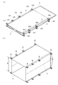
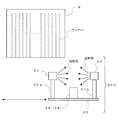
- FIG. 7 is a diagram showing an example of a state of the wafer housed in the container B.
- FIG. 7A shows the appearance of the container B
- FIG. 7B is a schematic vertical sectional view of the container B accommodating a large number of wafers.
- each of a large number of wafers is housed in the container B at a predetermined interval.
- a guide groove (not shown) corresponding to the thickness of the wafer is formed on the inner wall of the container B so that adjacent wafers do not come into contact with each other.
- the guide groove is formed by providing a predetermined clearance so that unnecessary pressure or the like is not applied to the surface of the wafer when the wafer is inserted into or taken out from the container B. In this way, the wafer is housed in the container B in the state shown in FIGS. 7A and 7B.
- the pre-process of the packaging process there may be a case where the number of wafers to be accommodated in the container B is insufficient, or a plurality of wafers are accommodated in one wafer accommodating place. is there.
- the wafer may be accommodated diagonally across the adjacent guide groove. In such a housed state, even if it is sealed with high sealing quality (sealing property), it cannot be shipped.
- the packaged products are managed in lot units, if even one defective product occurs, all the lots will be subject to re-inspection, etc., so it is possible to make the quality at the time of shipment more reliable. You will need it.
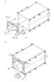
- the wafer registration detection mechanism 300 functions as a registration inspection device, which is the first shipping inspection device.
- the wafer registration detection mechanism 300 included in the packaging device includes a light source 30 (first light source), a light source 31 (second light source), frames 30a and 31a holding each light source, and a light source 30 that irradiate light toward the container B.
- 31 includes light receiving units 35 and 36 that receive the reflected light of the light emitted from the 31 and the base 40.
- the wafer registration detection mechanism 300 can move in parallel with the container B by a driving force from a driving unit (not shown). Further, the start or stop of the movement of the wafer registration detection mechanism 300 is controlled by the control unit 20. Further, the control unit 20 controls to specify the accommodation state of the wafer housed in the container B based on the detection results by the light receiving units 35 and 36.
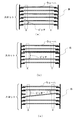
- FIG. 10 is a diagram for explaining an example of the state of the wafer when viewed from above the container.
- FIG. 10A shows a state in which wafers are housed one by one in one-stage slot, and the wafers are normally housed in the container B.
- FIG. 10B shows a state in which a plurality of wafers are stored in one-stage slot (sometimes referred to as a double slot), which is an example of an illegal storage state.
- FIG. 10C shows a state in which one wafer is stored across a plurality of slots (sometimes referred to as a cross slot), which is an example of an illegal storage state.
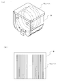
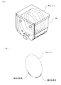
- FIG. 11 is a diagram for explaining the appearance of the container B (FIG. 11 (a)) and the linear reflected light (FIG. 11 (b)) described later.
- the wafer accommodation state is the normal accommodation state or the incorrect accommodation state is determined based on, for example, the detection result of the reflected light in the dotted square areas X and Y shown in FIG. 10, and then the wafer is accommodated. Identify the state.
- the light receiving units 35 and 36 can be configured to receive linear reflected light (linear reflected light). The identification of the accommodation state based on the linear reflected light can be specified with higher accuracy than the identification of the accommodation state based on, for example, the point-shaped reflected light.
- the accommodation state of the wafer is specified based on the detection result of the reflected light in the regions X and Y, the region X and the region Y shown in FIG. Detects the presence or absence of. Therefore, the accommodation state can be specified with higher accuracy when it is performed based on the linear reflected light than when it is performed based on the point-shaped reflected light.
- the end surface (thickness surface) of the detection target (wafer) is curved, and the linear reflected light returned by illuminating the end surface (thickness surface) is emitted. It is used for wafer detection. Since the surface to be detected is a three-dimensional curved surface, linear reflected light may not be detected well depending on the positional relationship between the image pickup device and the illumination. Therefore, auxiliary illumination that follows the scanning operation of the image pickup device is added, and the illumination conditions As a result, the configuration may be such that the stabilization of the reflected light is improved.
- the wafer accommodation state may differ for each container, such as wafers being stored in some slots of the container B. Therefore, information indicating how the wafer is stored in the container B (information indicating in which slot the wafer is stored) is stored in advance in association with information that uniquely identifies each container B, and these are stored. By comparing the information in the above with the detection result of the reflected light, it may be configured to determine whether the wafer accommodating state is a normal accommodating state or an improper accommodating state.
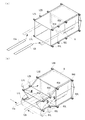
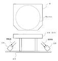
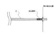
- FIG. 12 is a diagram for explaining the state detection of the sealing portion by the sealing state detection mechanism included in the packaging device according to the present embodiment.
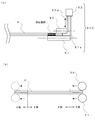
- FIG. 13 is a diagram for explaining an example of the configuration of the sealing state detection mechanism 500.
- the sealing state detection mechanism 500 functions as a sealing state inspection device, which is a second shipping inspection device. The operation of the sealing state detection mechanism will be described with reference to FIGS. 12 and 13.
- the sealing state detection mechanism 500 included in the packaging device includes rollers 50 and 51, guides 50a and 51a, and a sensor 52.
- the sealing state detection mechanism 500 releases the operation of holding the bag mouth between the rollers 50 and 51, the operation of moving along the bag mouth, and the holding of the bag mouth by the driving force from the driving unit (not shown). Performs an operation such as detaching from the bag mouth. Further, these operations are controlled by the control unit 20.
- the sealing state detection mechanism 500 In the confirmation of the sealing state by the sealing state detection mechanism 500, when wrinkles are generated on the sealing surface, detection is performed focusing on the occurrence of "scratch” or “twist” in the vicinity of the sealing surface. It is configured to scan and detect the thickness in the vicinity of the sealing portion (see FIG. 12) which is the sealing surface.
- FIG. 11 shows an example of detecting the thickness in the vicinity of the sealing portion on the bag mouth side, the thickness in the vicinity of the sealing portion on the opposite side may be detected.
- the bag mouth is narrowed by the rollers 50 and 51 included in the sealing state detection mechanism 500. Further, the roller 50 is formed so as to detect the thickness in the vicinity of the sealing portion, and as shown in FIG. 13A, the roller 50 is formed so as to be relatively shorter than the roller 51. To. The roller 50 is connected to the sensor 52 via the guide 50a, and the roller 51 is connected to the sensor 52 via the guide 51a.
- the sensor 52 can detect the thickness in the vicinity of the sealing portion (sealing surface) on the bag mouth side by detecting the vertical movement of the roller 50 with reference to the position of the roller 51. Further, by moving the rollers 50 and 51 horizontally along the bag mouth as shown in FIG. 13B, it is possible to detect a change in the thickness in the vicinity of the sealing portion (sealing surface) on the bag mouth side.
- the thickness of the sealing portion is the thickness of two sheets and the thickness of four sheets (see FIG. 13B).
- the reason why the detection is performed by scanning the vicinity of the sealing location instead of the sealing location is that a predetermined pressure is applied to the upper and lower sealing bases during heating (fusion) by the heating wire during sealing.
- the surface is pressurized to improve the adhesion between the sheets. Therefore, even if there are some wrinkles, they will be crushed by pressurization, the difference in thickness between the wrinkled part and the normal part will be small, and the detection will be very severe when the sealed part is scanned. The point can be mentioned.
- the wrinkles at the sealing portion are crushed by pressure, whereas the molding (wrinkle crushing) action by pressure during sealing is not applied.
- the sealing state detection mechanism 500 is configured to measure not the sealing part itself but the vicinity thereof. Will be done.
- the bag mouth is heated and the sealing surface is fused and cured to be sealed (fused seal). Therefore, the area to be fused and sealed on the sealing surface, the heating time, the heating temperature, etc. are appropriately set according to the thickness of the gusset bag P, the material of the material, etc., but changes in the surrounding environment of the device and variations in the gusset bag P
- the surface condition of the sealing surface may change depending on such factors. In addition, it may be hardened by heating, and in this respect as well, a complicated configuration is required when detecting a change in the thickness of the sealed portion itself.
- the sealing state detection mechanism 500 is configured to detect the presence or absence of "screw” or “twist” generated in the vicinity of the sealing portion (seal surface) as a change in thickness. Therefore, it is less affected by the change caused by the fusion seal as described above, and the structure is relatively simple, and whether the sealing portion (seal surface) is wrinkled. It is also possible to improve the detection accuracy of whether or not. In this way, the seal quality (sealability) can be confirmed.
- the packaging device packaging system
- the tensile force applied by the mouthpiece M when shaping the bag mouth can secure the frictional force between the outer surface of each shaped part and the inner wall of the gusset bag P necessary for holding the gusset bag P. it can.
- the folding of the bag mouth maintains a state in which the upper sealing surface and the lower sealing surface are stretched so as not to loosen (a state in which wrinkles do not occur). This is done by moving each clamp while moving. As a result, it is possible to improve the sealing quality (sealing property) at the time of fusion sealing. Further, when the bag mouth is folded, the gusset bag P containing the work is not dragged and the bag mouth is folded. Therefore, unnecessary tension is not applied to the gusset bag P, and the upper sealing surface and the lower sealing surface can be more reliably maintained in a stretched state so as not to loosen.
- the packaging device (packaging system) according to the present embodiment has a wafer registration detection mechanism 300 and a sealing state detection mechanism 500 as a configuration for making the quality at the time of shipment more reliable. Based on the detection result by the mechanism, it becomes possible to obtain evidence that the shipped product is a normal product.
- the sealing surface (bag mouth pre-length portion) after the fusion sealing is completed is fixed by bending the bag-setting means downward (not shown). In this way, a series of packaging operations is completed.
- FIG. 14 is an explanatory diagram of a main control procedure by the control unit 20 when executing the packaging processing method.
- the control unit 20 starts control when the operator of the packaging system S receives an input of a start instruction.
- the control unit 20 conveys the gusset bag P from the bag storage stage S4 to the packaging stage S1. Further, the transport arm 10 holds the work (container B) stored in the container storage stage S3, and the wafer storage state of the wafer stored in the container B is specified via the wafer registration detection mechanism 300. When the wafer housed in the container B is in the normal state, the control unit 20 then transfers the container B to the transfer stage S2. If the accommodation state is incorrect, for example, the number of wafers to be accommodated in the container B is insufficient, or if a plurality of wafers are accommodated in the accommodation location of one wafer, the operator Notify the abnormality. The control unit 20 determines whether or not the series of preprocessing has been completed (S101).
- the control unit 20 When it is determined that the preprocessing is completed (S101: Yes), the control unit 20 issues an instruction to a clamp drive mechanism (not shown), and each clamp (L1U to L4U, L1L to L4L, R1U to R4U, R1L to R4L), respectively. Is moved to a predetermined arrangement position to start sandwiching (clamping) the adhesive band D (S102). If this is not the case (S101: No), the control unit 20 waits for the transition to the next process until the preprocess is completed.
- the control unit 20 gives an instruction to a clamp drive mechanism (not shown) in order to open (open) the bag mouth of the gusset bag P, and clamps L1U, L2U, L3U, which sandwich the adhesive band D on the upper surface side of the gusset bag P. L4U, R1U, R2U, R3U, and R4U are moved upward (S103).
- a sensor S103: Yes
- the control unit 20 issues an instruction to a mouthpiece drive mechanism (not shown) to insert the mouthpiece M from the bag mouth (S104). If not (S103: No), the process returns to step S103.
- the detection that the bag mouth is opened is, for example, a position sensor that detects that each of the clamps L1U, L2U, L3U, L4U, R1U, R2U, R3U, and R4U has moved to a predetermined position above, or is folded. It can be detected by using a proximity sensor or the like that detects that the gusset portion in the state becomes flat due to the opening of the bag mouth.
- the control unit 20 issues an instruction to a mouthpiece drive mechanism (not shown) to shape the bag mouth with each of the shaping parts (shaped parts 11a to 11d) constituting the mouthpiece M and the bag mouth lower side protective plate 11e (S105).
- a mouthpiece drive mechanism not shown
- the control unit 20 determines that the shaping of the bag mouth is completed based on the detection result of the tension sensor (not shown) (S105: Yes)
- the control unit 20 issues an instruction to the transport mechanism (not shown) and holds the work (container B) held by the transport arm 10. ) To a predetermined position in the gusset bag P (S106). If not (S105: No), the process returns to step S105.
- the control unit 20 issues an instruction to a transfer mechanism (not shown) when the work insertion is completed, releases the work holding of the transfer arm 10 and retracts the work to the transfer stage S2, and then gives an instruction to the mouthpiece drive mechanism (not shown). Take it out and separate the mouthpiece M from the bag mouth (S107).
- the completion of work insertion can be detected by using, for example, a position sensor that detects that the transport arm 10 has moved to a predetermined position.
- the control unit 20 issues an instruction to a folded plate drive mechanism (not shown) and moves the folded plates 12a and 12b to the folding start position (S108).
- the control unit 20 gives an instruction to a clamp drive mechanism (not shown) and a folded plate drive mechanism (not shown) to start folding the bag mouth by each clamp and the folded plates 12a and 12b (S109).
- the control unit 20 determines whether or not the folding of the bag mouth is completed (S110).
- control unit 20 issues an instruction to the folded plate drive mechanism (not shown) to separate the folded plates 12a and 12b from the bag mouth (S111). If not (S110: No), the process returns to step S110.
- the control unit 20 gives an instruction to a seal base drive mechanism (not shown), moves the upper seal base 13a and the lower seal base 13b to the seal start position, and then starts the fusion seal (seal processing) (S112).
- a seal base drive mechanism not shown
- the control unit 20 issues an instruction to a seal base drive mechanism (not shown) to move the upper seal base 13a and the lower seal base 13b to the standby position.
- the control unit 20 detects the state of the sealing portion (sealing surface) via the sealing state detecting mechanism 500. To confirm the seal quality (sealing property), for example, when a thickness change exceeding a predetermined threshold value is detected, the operator is notified of the abnormality as the sealing property may be insufficient.
- the control unit 20 issues an instruction to a clamp drive mechanism (not shown) to release the clamping of the adhesive band D by each clamp (S114). In this way, a series of processes is completed.
- the packaging device (packaging system) has the wafer registration detection mechanism 300 and the sealing state detection mechanism 500, and the shipped product is a normal product based on the detection results by these mechanisms. It is possible to obtain evidence that there is. It should be noted that, not only when the wafer registration detection mechanism 300 and the sealing state detection mechanism 500 are provided, but also when the packaging device (packaging system) is provided with either one, evidence indicating that the shipped product is a normal product is obtained. be able to. Further, the wafer registration detection mechanism 300 and the sealing state detection mechanism 500 are shipped so that the wafer registration detection mechanism 300, the sealing state detection mechanism 500 and the like can be arranged in the packaging device (packaging system) already in operation. It can also be configured as an inspection device.
- the wafer registration detection mechanism 300 has a plurality of light sources and a plurality of receivers, and the light source and the receiver are used properly according to the shape of the container. For example, it is possible to deal with container shapes that have many variations depending on the container manufacturer and product number. In addition, it is possible to prevent reflection (halation) on the surface of the container and to cope with the existence of opaque parts, which cannot be dealt with when a single combination of light source / receiver is used.
- the container has an almost transparent appearance, there are scratches / foreign substances existing on the inner and outer surfaces of the container and dividing lines of the injection molding die generated in the container manufacturing process. Since these are large disturbances to the detection of linear reflected light used for wafer enrollment detection, the false detection rate is high and it is not practical, so it is difficult to carry out automatic inspection from the outside of the container. there were.
- the wafer registration detection mechanism 300 the influence of foreign matter, scratches, and dividing lines that become disturbances can be minimized by devising the illumination / receiver arrangement and scanning operation, and the reliability of wafer registration detection can be raised to a practical level.
Landscapes
- Engineering & Computer Science (AREA)
- Mechanical Engineering (AREA)
- Physics & Mathematics (AREA)
- Condensed Matter Physics & Semiconductors (AREA)
- General Physics & Mathematics (AREA)
- Manufacturing & Machinery (AREA)
- Computer Hardware Design (AREA)
- Microelectronics & Electronic Packaging (AREA)
- Power Engineering (AREA)
- Supplying Of Containers To The Packaging Station (AREA)
- Container, Conveyance, Adherence, Positioning, Of Wafer (AREA)
- Closing Of Containers (AREA)
Priority Applications (4)
| Application Number | Priority Date | Filing Date | Title |
|---|---|---|---|
| JP2021525408A JP7313728B2 (ja) | 2019-06-10 | 2019-06-10 | 出荷検査装置、これを有する包装装置および包装システム |
| CN201980097122.8A CN114007942B (zh) | 2019-06-10 | 2019-06-10 | 一种出厂检查装置、具有该装置的包装装置及包装系统 |
| KR1020227000712A KR102744895B1 (ko) | 2019-06-10 | 2019-06-10 | 출하 검사 장치, 이것을 갖는 포장 장치 및 포장 시스템 |
| PCT/JP2019/022875 WO2020250267A1 (ja) | 2019-06-10 | 2019-06-10 | 出荷検査装置、これを有する包装装置および包装システム |
Applications Claiming Priority (1)
| Application Number | Priority Date | Filing Date | Title |
|---|---|---|---|
| PCT/JP2019/022875 WO2020250267A1 (ja) | 2019-06-10 | 2019-06-10 | 出荷検査装置、これを有する包装装置および包装システム |
Publications (1)
| Publication Number | Publication Date |
|---|---|
| WO2020250267A1 true WO2020250267A1 (ja) | 2020-12-17 |
Family
ID=73782135
Family Applications (1)
| Application Number | Title | Priority Date | Filing Date |
|---|---|---|---|
| PCT/JP2019/022875 Ceased WO2020250267A1 (ja) | 2019-06-10 | 2019-06-10 | 出荷検査装置、これを有する包装装置および包装システム |
Country Status (4)
| Country | Link |
|---|---|
| JP (1) | JP7313728B2 (enExample) |
| KR (1) | KR102744895B1 (enExample) |
| CN (1) | CN114007942B (enExample) |
| WO (1) | WO2020250267A1 (enExample) |
Cited By (4)
| Publication number | Priority date | Publication date | Assignee | Title |
|---|---|---|---|---|
| CN114889867A (zh) * | 2022-05-13 | 2022-08-12 | 漳州佳龙科技股份有限公司 | 一种真空包装二次装袋机及其工作方法 |
| CN114889866A (zh) * | 2022-05-13 | 2022-08-12 | 漳州佳龙科技股份有限公司 | 一种推包机构及其工作方法 |
| EP4273910A1 (de) * | 2022-05-05 | 2023-11-08 | Siltronic AG | Vorrichtung zum verpacken von waferkassetten |
| WO2024048222A1 (ja) * | 2022-08-30 | 2024-03-07 | オリオン機械工業株式会社 | ガセット袋の封止方法 |
Families Citing this family (1)
| Publication number | Priority date | Publication date | Assignee | Title |
|---|---|---|---|---|
| CN114379830B (zh) * | 2022-03-23 | 2022-06-10 | 南京伟测半导体科技有限公司 | 一种晶舟盒内晶圆位置检测装置 |
Citations (4)
| Publication number | Priority date | Publication date | Assignee | Title |
|---|---|---|---|---|
| JPS63253205A (ja) * | 1987-04-09 | 1988-10-20 | Nichizou Tec:Kk | チユ−ブシ−ル等の異常検出装置 |
| JPH04142231A (ja) * | 1990-09-21 | 1992-05-15 | Anritsu Corp | 包装機 |
| JP2005064515A (ja) * | 2003-08-15 | 2005-03-10 | Asm Internatl Nv | 閉じたウェハカセットの内部に配置されたウェハのマッピングのための方法および装置 |
| JP2015058958A (ja) * | 2013-09-19 | 2015-03-30 | ミクロ技研株式会社 | 包装装置および包装システム |
Family Cites Families (4)
| Publication number | Priority date | Publication date | Assignee | Title |
|---|---|---|---|---|
| CN102576687B (zh) * | 2009-11-17 | 2015-11-25 | 昕芙旎雅有限公司 | 晶圆检测装置 |
| JP5407961B2 (ja) | 2010-03-18 | 2014-02-05 | 信越半導体株式会社 | 容器包装装置 |
| JP5639958B2 (ja) * | 2011-05-27 | 2014-12-10 | 日東電工株式会社 | 半導体ウエハマウント方法および半導体ウエハマウント装置 |
| JP2017037910A (ja) * | 2015-08-07 | 2017-02-16 | 日東電工株式会社 | 半導体ウエハの搬送方法および半導体ウエハの搬送装置 |
-
2019
- 2019-06-10 CN CN201980097122.8A patent/CN114007942B/zh active Active
- 2019-06-10 KR KR1020227000712A patent/KR102744895B1/ko active Active
- 2019-06-10 JP JP2021525408A patent/JP7313728B2/ja active Active
- 2019-06-10 WO PCT/JP2019/022875 patent/WO2020250267A1/ja not_active Ceased
Patent Citations (4)
| Publication number | Priority date | Publication date | Assignee | Title |
|---|---|---|---|---|
| JPS63253205A (ja) * | 1987-04-09 | 1988-10-20 | Nichizou Tec:Kk | チユ−ブシ−ル等の異常検出装置 |
| JPH04142231A (ja) * | 1990-09-21 | 1992-05-15 | Anritsu Corp | 包装機 |
| JP2005064515A (ja) * | 2003-08-15 | 2005-03-10 | Asm Internatl Nv | 閉じたウェハカセットの内部に配置されたウェハのマッピングのための方法および装置 |
| JP2015058958A (ja) * | 2013-09-19 | 2015-03-30 | ミクロ技研株式会社 | 包装装置および包装システム |
Cited By (7)
| Publication number | Priority date | Publication date | Assignee | Title |
|---|---|---|---|---|
| EP4273910A1 (de) * | 2022-05-05 | 2023-11-08 | Siltronic AG | Vorrichtung zum verpacken von waferkassetten |
| WO2023213596A1 (de) * | 2022-05-05 | 2023-11-09 | Siltronic Ag | Vorrichtung zum verpacken von waferkassetten |
| JP2025515089A (ja) * | 2022-05-05 | 2025-05-13 | ジルトロニック アクチエンゲゼルシャフト | ウェハカセット梱包装置 |
| CN114889867A (zh) * | 2022-05-13 | 2022-08-12 | 漳州佳龙科技股份有限公司 | 一种真空包装二次装袋机及其工作方法 |
| CN114889866A (zh) * | 2022-05-13 | 2022-08-12 | 漳州佳龙科技股份有限公司 | 一种推包机构及其工作方法 |
| CN114889866B (zh) * | 2022-05-13 | 2024-04-26 | 漳州佳龙科技股份有限公司 | 一种推包机构及其工作方法 |
| WO2024048222A1 (ja) * | 2022-08-30 | 2024-03-07 | オリオン機械工業株式会社 | ガセット袋の封止方法 |
Also Published As
| Publication number | Publication date |
|---|---|
| KR102744895B1 (ko) | 2024-12-19 |
| JP7313728B2 (ja) | 2023-07-25 |
| JPWO2020250267A1 (enExample) | 2020-12-17 |
| CN114007942B (zh) | 2024-07-05 |
| KR20220018043A (ko) | 2022-02-14 |
| CN114007942A (zh) | 2022-02-01 |
Similar Documents
| Publication | Publication Date | Title |
|---|---|---|
| JP7313728B2 (ja) | 出荷検査装置、これを有する包装装置および包装システム | |
| JP5547840B1 (ja) | 包装装置および包装システム | |
| JP3926149B2 (ja) | ロール状物の自動包装方法およびシステム | |
| CN105319038A (zh) | 包装袋的检查方法以及包装袋的检查装置 | |
| AU772942B2 (en) | Heat seal apparatus for lens packages | |
| US6576390B1 (en) | Method of and apparatus for manufacturing instant photographic film units | |
| CN111383984A (zh) | 片状粘合材料的粘贴方法和片状粘合材料的粘贴装置 | |
| JP2021042076A (ja) | フィルムロール粘着テープの剥離装置 | |
| WO2016088713A1 (ja) | チューブ容器検査装置 | |
| JP2009276102A (ja) | ポケット形状検査装置 | |
| US11884436B2 (en) | Apparatus for the packaging of containers of devices for pharmaceutical use | |
| JP7716171B2 (ja) | フィルムロール供給装置、フィルム供給システム、及び、フィルムロール | |
| CN111383982A (zh) | 片状粘合材料的粘贴方法和片状粘合材料的粘贴装置 | |
| CN111383983A (zh) | 片状粘合材料的粘贴方法和片状粘合材料的粘贴装置 | |
| CN111383985A (zh) | 片状粘合材料的切断方法和片状粘合材料的切断装置 | |
| WO2022269460A1 (en) | Apparatus for the packaging of containers of devices for pharmaceutical use | |
| JP2006143231A (ja) | シュリンクフィルム及び物品、並びに、それらに関連する処理装置、検査方法及び製造方法、 | |
| JP4753825B2 (ja) | 箱嵌合方法及び装置、及び外装箱の製造システム | |
| TWI860701B (zh) | 用於包裝晶圓匣的設備及方法 | |
| JP3413310B2 (ja) | 写真フイルムパトローネのフレキシブルディスクの検査方法及び装置 | |
| EP1749749B1 (en) | Horizontal package handling machine | |
| JP2003211809A (ja) | 押印処理機 | |
| JP2024178497A (ja) | 包装体の検査装置 | |
| JP2007085907A (ja) | 充填容器の検査装置 | |
| JP2015129011A (ja) | 多層フィルム製袋品の製造装置 |
Legal Events
| Date | Code | Title | Description |
|---|---|---|---|
| 121 | Ep: the epo has been informed by wipo that ep was designated in this application |
Ref document number: 19932285 Country of ref document: EP Kind code of ref document: A1 |
|
| ENP | Entry into the national phase |
Ref document number: 2021525408 Country of ref document: JP Kind code of ref document: A |
|
| NENP | Non-entry into the national phase |
Ref country code: DE |
|
| ENP | Entry into the national phase |
Ref document number: 20227000712 Country of ref document: KR Kind code of ref document: A |
|
| 122 | Ep: pct application non-entry in european phase |
Ref document number: 19932285 Country of ref document: EP Kind code of ref document: A1 |