WO2020249995A1 - 走行支援方法および走行支援装置 - Google Patents
走行支援方法および走行支援装置 Download PDFInfo
- Publication number
- WO2020249995A1 WO2020249995A1 PCT/IB2019/000634 IB2019000634W WO2020249995A1 WO 2020249995 A1 WO2020249995 A1 WO 2020249995A1 IB 2019000634 W IB2019000634 W IB 2019000634W WO 2020249995 A1 WO2020249995 A1 WO 2020249995A1
- Authority
- WO
- WIPO (PCT)
- Prior art keywords
- static
- route
- dynamic
- vehicle
- travel
- Prior art date
- Legal status (The legal status is an assumption and is not a legal conclusion. Google has not performed a legal analysis and makes no representation as to the accuracy of the status listed.)
- Ceased
Links
Images


Classifications
-
- B—PERFORMING OPERATIONS; TRANSPORTING
- B60—VEHICLES IN GENERAL
- B60W—CONJOINT CONTROL OF VEHICLE SUB-UNITS OF DIFFERENT TYPE OR DIFFERENT FUNCTION; CONTROL SYSTEMS SPECIALLY ADAPTED FOR HYBRID VEHICLES; ROAD VEHICLE DRIVE CONTROL SYSTEMS FOR PURPOSES NOT RELATED TO THE CONTROL OF A PARTICULAR SUB-UNIT
- B60W60/00—Drive control systems specially adapted for autonomous road vehicles
- B60W60/001—Planning or execution of driving tasks
- B60W60/0013—Planning or execution of driving tasks specially adapted for occupant comfort
-
- B—PERFORMING OPERATIONS; TRANSPORTING
- B60—VEHICLES IN GENERAL
- B60W—CONJOINT CONTROL OF VEHICLE SUB-UNITS OF DIFFERENT TYPE OR DIFFERENT FUNCTION; CONTROL SYSTEMS SPECIALLY ADAPTED FOR HYBRID VEHICLES; ROAD VEHICLE DRIVE CONTROL SYSTEMS FOR PURPOSES NOT RELATED TO THE CONTROL OF A PARTICULAR SUB-UNIT
- B60W2520/00—Input parameters relating to overall vehicle dynamics
- B60W2520/10—Longitudinal speed
- B60W2520/105—Longitudinal acceleration
-
- B—PERFORMING OPERATIONS; TRANSPORTING
- B60—VEHICLES IN GENERAL
- B60W—CONJOINT CONTROL OF VEHICLE SUB-UNITS OF DIFFERENT TYPE OR DIFFERENT FUNCTION; CONTROL SYSTEMS SPECIALLY ADAPTED FOR HYBRID VEHICLES; ROAD VEHICLE DRIVE CONTROL SYSTEMS FOR PURPOSES NOT RELATED TO THE CONTROL OF A PARTICULAR SUB-UNIT
- B60W2552/00—Input parameters relating to infrastructure
- B60W2552/50—Barriers
-
- B—PERFORMING OPERATIONS; TRANSPORTING
- B60—VEHICLES IN GENERAL
- B60W—CONJOINT CONTROL OF VEHICLE SUB-UNITS OF DIFFERENT TYPE OR DIFFERENT FUNCTION; CONTROL SYSTEMS SPECIALLY ADAPTED FOR HYBRID VEHICLES; ROAD VEHICLE DRIVE CONTROL SYSTEMS FOR PURPOSES NOT RELATED TO THE CONTROL OF A PARTICULAR SUB-UNIT
- B60W2552/00—Input parameters relating to infrastructure
- B60W2552/53—Road markings, e.g. lane marker or crosswalk
-
- B—PERFORMING OPERATIONS; TRANSPORTING
- B60—VEHICLES IN GENERAL
- B60W—CONJOINT CONTROL OF VEHICLE SUB-UNITS OF DIFFERENT TYPE OR DIFFERENT FUNCTION; CONTROL SYSTEMS SPECIALLY ADAPTED FOR HYBRID VEHICLES; ROAD VEHICLE DRIVE CONTROL SYSTEMS FOR PURPOSES NOT RELATED TO THE CONTROL OF A PARTICULAR SUB-UNIT
- B60W2554/00—Input parameters relating to objects
- B60W2554/20—Static objects
-
- B—PERFORMING OPERATIONS; TRANSPORTING
- B60—VEHICLES IN GENERAL
- B60W—CONJOINT CONTROL OF VEHICLE SUB-UNITS OF DIFFERENT TYPE OR DIFFERENT FUNCTION; CONTROL SYSTEMS SPECIALLY ADAPTED FOR HYBRID VEHICLES; ROAD VEHICLE DRIVE CONTROL SYSTEMS FOR PURPOSES NOT RELATED TO THE CONTROL OF A PARTICULAR SUB-UNIT
- B60W2554/00—Input parameters relating to objects
- B60W2554/40—Dynamic objects, e.g. animals, windblown objects
- B60W2554/404—Characteristics
- B60W2554/4041—Position
-
- B—PERFORMING OPERATIONS; TRANSPORTING
- B60—VEHICLES IN GENERAL
- B60W—CONJOINT CONTROL OF VEHICLE SUB-UNITS OF DIFFERENT TYPE OR DIFFERENT FUNCTION; CONTROL SYSTEMS SPECIALLY ADAPTED FOR HYBRID VEHICLES; ROAD VEHICLE DRIVE CONTROL SYSTEMS FOR PURPOSES NOT RELATED TO THE CONTROL OF A PARTICULAR SUB-UNIT
- B60W2556/00—Input parameters relating to data
- B60W2556/40—High definition maps
-
- B—PERFORMING OPERATIONS; TRANSPORTING
- B60—VEHICLES IN GENERAL
- B60W—CONJOINT CONTROL OF VEHICLE SUB-UNITS OF DIFFERENT TYPE OR DIFFERENT FUNCTION; CONTROL SYSTEMS SPECIALLY ADAPTED FOR HYBRID VEHICLES; ROAD VEHICLE DRIVE CONTROL SYSTEMS FOR PURPOSES NOT RELATED TO THE CONTROL OF A PARTICULAR SUB-UNIT
- B60W2556/00—Input parameters relating to data
- B60W2556/45—External transmission of data to or from the vehicle
- B60W2556/50—External transmission of data to or from the vehicle of positioning data, e.g. GPS [Global Positioning System] data
-
- B—PERFORMING OPERATIONS; TRANSPORTING
- B60—VEHICLES IN GENERAL
- B60W—CONJOINT CONTROL OF VEHICLE SUB-UNITS OF DIFFERENT TYPE OR DIFFERENT FUNCTION; CONTROL SYSTEMS SPECIALLY ADAPTED FOR HYBRID VEHICLES; ROAD VEHICLE DRIVE CONTROL SYSTEMS FOR PURPOSES NOT RELATED TO THE CONTROL OF A PARTICULAR SUB-UNIT
- B60W2720/00—Output or target parameters relating to overall vehicle dynamics
- B60W2720/12—Lateral speed
- B60W2720/125—Lateral acceleration
-
- G—PHYSICS
- G08—SIGNALLING
- G08G—TRAFFIC CONTROL SYSTEMS
- G08G1/00—Traffic control systems for road vehicles
- G08G1/16—Anti-collision systems
- G08G1/166—Anti-collision systems for active traffic, e.g. moving vehicles, pedestrians, bikes
-
- G—PHYSICS
- G08—SIGNALLING
- G08G—TRAFFIC CONTROL SYSTEMS
- G08G1/00—Traffic control systems for road vehicles
- G08G1/16—Anti-collision systems
- G08G1/167—Driving aids for lane monitoring, lane changing, e.g. blind spot detection
Definitions
- the present invention relates to a travel support method and a travel support device that support the travel of a vehicle.
- a driving support device including a travel route information acquisition means for acquiring a plurality of travel route information having different recognition ranges and a route generation means for generating a route of the own vehicle using a plurality of travel route information according to the driving environment is known.
- the plurality of travel route information includes, for example, a wide area map used for determining a rough travel route from the start point of the own vehicle to the destination, and a medium used for recognizing pedestrians and other vehicles and predicting movement. Examples include a local map used for detecting and avoiding the movement of pedestrians and other vehicles that cannot be recognized by the area map and the middle area map.
- the problem to be solved by the present invention is to provide a running support method and a running support device capable of making a running plan that balances the response to the surrounding environment and smooth running.
- the present invention acquires information on the static track boundary, which is the boundary between the track of the own vehicle and other than the track, acquires information on the dynamic track boundary, which is information on the boundary different from the static track boundary, and is static.
- a static driving route is generated as a running route on which the own vehicle can travel, and based on the information on the static driving route and the dynamic driving route boundary, the driving route is shorter than the static driving route and the surrounding area.
- FIG. 1 is a block diagram showing a traveling support device according to an embodiment of the present invention.
- FIG. 2 is a block diagram showing each function included in the control device shown in FIG.
- FIG. 3 is a diagram for explaining a static traveling route.
- FIG. 4 is a diagram for explaining various information used for generating a dynamic traveling route.
- FIG. 5 is a diagram for explaining a method of combining a static traveling route and a dynamic traveling route.
- FIG. 6 is a diagram for explaining an example of a method of calculating a control command value.
- FIG. 7 is a diagram for explaining the calculation cycle and the calculation load of the processor in each process of the control device.
- FIG. 8A is a diagram for explaining a correction process for a static traveling route.
- FIG. 8B is a diagram of a static travel route in each block shown in FIG. 8A.
- FIG. 9 is a block diagram showing a flow of control processing according to the present embodiment.
- FIG. 1 is a diagram showing a configuration of a vehicle traveling support device 100 according to an embodiment of the present invention.
- the traveling support device 100 includes a vehicle position detection device 110, a map database 120, a vehicle speed sensor 130, a distance measurement sensor 140, a camera 150, and a drive mechanism 170.
- the control device 180 and the yaw rate sensor 190 are provided. These devices are connected by a CAN (Control Area Network) or other in-vehicle LAN in order to exchange information with each other.
- CAN Controller Area Network
- the own vehicle position detection device 110 includes a GPS unit.
- the own vehicle position detection device 110 detects radio waves transmitted from a plurality of satellite communications by a locator (GPS antenna), and periodically acquires the position information of the own vehicle.
- the own vehicle position detection device 110 detects the current position of the own vehicle based on the acquired position information of the own vehicle, the angle change information acquired from the gyro sensor (not shown), and the vehicle speed acquired from the vehicle speed sensor 130. To do.
- the own vehicle position detection device 110 can also detect the position of the own vehicle on the map by using a well-known map matching technique.
- the position information of the own vehicle detected by the own vehicle position detection device 110 is output to the control device 180.
- Map information is stored in the map database 120.
- the map information stored in the map database 120 includes road attribute information at each map coordinate. Examples of road attributes include curves, slopes, intersections, interchanges, narrow roads, straight roads, and confluences. These road attributes are examples and do not limit the road attributes.
- Road attributes include information on road shape and road slope.
- the map information also includes information on the center line of the lane and the curvature of the lane.
- the center line of a lane is the center line of a lane along the traveling direction of a vehicle, and is defined in units of lanes.
- the lane curvature is the curvature at the center line of the lane and is defined in lane units.
- the map information includes information on the track boundary.
- the track boundary is the boundary between the track of the own vehicle and the rest.
- the runway of the own vehicle is a road for the own vehicle to travel.
- the track boundary is the boundary that forms the road on which the own vehicle travels.
- the track boundary is located on each of the left and right sides with respect to the traveling direction of the own vehicle.
- the track boundary may be defined in lane units or in road units.
- Examples of the map information including the information on the track boundary include high-precision map information suitable for automatic driving.
- the high-precision map information may be acquired by communication with a server or system provided outside the own vehicle, or may be stored in the map database 120 in advance.
- the static track boundary is composed of road shape and road width information stored as map information.
- the static track boundary is information that is not updated unless the map information is updated.
- the track boundary is set in advance in the map information for a point (for example, inside an intersection) where the track boundary cannot be clearly specified.
- the preset track boundary is a fictitious track boundary, not a road marking or road structure that actually exists.
- the static track boundary may be composed of information on the position on the map in addition to the road shape and the road width.
- the map information also includes traffic rule information that the vehicle must comply with when driving.
- the traffic rule information includes, but is not limited to, for example, pausing on the route, parking / stopping prohibition, slowing down, speed limit (legal speed), and lane change prohibition. Traffic rule information is specified for each lane. Note that these pieces of information included in the map information are defined by nodes and links connecting the nodes (also referred to as road links).
- the vehicle speed sensor 130 measures the rotational speed of a drive system such as a drive shaft, and detects the traveling speed of the own vehicle (hereinafter, also referred to as vehicle speed) based on this.
- the vehicle speed information of the own vehicle detected by the vehicle speed sensor 130 is output to the control device 180.
- the yaw rate sensor 190 is mounted in the vehicle interior, for example, and detects the yaw rate (change speed of the rotation angle in the turning direction) of the own vehicle.
- the yaw rate information of the own vehicle detected by the yaw rate sensor 190 is output to the control device 180. Links are identified at the lane level.
- the ranging sensor 140 detects an object existing around the own vehicle. Further, the distance measuring sensor 140 calculates the relative distance between the own vehicle and the object, the direction in which the object is located with respect to the own vehicle, and the relative speed of the object with respect to the own vehicle.
- Objects include, for example, lane boundaries, centerlines, medians, guardrails, curbs, tunnels or side walls of highways. Examples of other objects include automobiles (other vehicles) other than the own vehicle, motorcycles, bicycles, road signs, traffic lights, pedestrian crossings, and the like. That is, the distance measuring sensor 140 is a kind of sensor that detects the surrounding environment of the own vehicle. The information of the object detected by the distance measuring sensor 140 is output to the control device 180.
- a distance measuring sensor 140 As such a distance measuring sensor 140, a laser radar, a millimeter wave radar, or the like (LRF or the like) can be used.
- the range-finding sensor 140 has a limited range in which an object can be detected, and detects an object existing within a predetermined range.
- the predetermined detection range differs depending on the type of sensor, and is defined for each type of sensor.
- the number of distance measuring sensors 140 is not particularly limited, and the distance measuring sensors 140 are provided, for example, in the front, side, and rear of the own vehicle. As a result, the distance measuring sensor 140 detects an object existing in the entire periphery of the own vehicle.
- the camera 150 captures images of roads and / or objects existing around the vehicle.
- the object imaged by the camera 150 is the same as the object detected by the distance measuring sensor 140.
- the camera 150 images the front of the own vehicle.
- the image information captured by the camera 150 is output to the control device 180.
- the camera 150 is a camera that images the front of the own vehicle and / or a camera that images the side of the own vehicle. Similar to the distance measuring sensor 140, the camera 150 also has a limited range in which an object can be imaged, and an object existing within a predetermined range is imaged.
- the imaging range of the camera 150 is narrower than the detection range of the ranging sensor 140, but in the present embodiment, the relationship between the imaging range of the camera 150 and the detection range of the ranging sensor 140 is particularly important. Not limited.
- the input device 160 is an operating member that can be operated by the driver.
- the driver can set on / off of the automatic driving control by operating the input device 160. Further, the driver can set the destination of the own vehicle by operating the input device 160.
- the drive mechanism 170 includes an engine and / or a motor (power system), a brake (braking system), a steering actuator (steering system), and the like for automatically traveling the own vehicle.
- the operation of the drive mechanism 170 is controlled by the control device 180 when the automatic operation control described later is performed.
- the control device 180 is a computer having a processor, and is a ROM (Read Only Memory) that stores a program for controlling the running of the own vehicle, and a CPU (Central Processing Unit) that executes the program stored in the ROM. ) And a RAM (Random Access Memory) that functions as an accessible storage device.
- ROM Read Only Memory
- CPU Central Processing Unit
- RAM Random Access Memory
- an operation circuit instead of or together with a CPU (Central Processing Unit), MPU (Micro Processing Unit), DSP (Digital Signal Processor), ASIC (Application Special Optical Programmable Circuit Programmable Circuit), etc. Can be used.
- the configuration in which the program executed by the control device 180 is stored in the ROM in advance will be described as an example, but the location where the program is stored is not limited to the ROM.
- the program may be stored on a computer-readable and portable computer-readable recording medium (eg, disk media, flash memory, etc.).
- the control device 180 executes a program downloaded from a computer-readable recording medium.
- the control device 180 may be configured to include only an operating circuit and download a program from the outside.
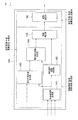
- FIG. 2 is a block diagram showing each function included in the control device 180.
- the control device 180 includes a own lane boundary generation unit 181, a static travel route generation unit 182, a travelable area generation unit 183, a dynamic travel route generation unit 184, and a route coupling unit. 185 and a path following unit 186 are included.
- These blocks realize each function described later by the software established in the ROM.
- the functions of the control device 180 are divided into six functional blocks, and then the functions of the respective functional blocks are described. However, the functions of the control device 180 need to be divided into six blocks. Instead, it may be divided into 5 or less functional blocks or 7 or more functional blocks.
- control device 180 is not limited to the function of the functional block described below, and also has, for example, a control function of the navigation system.
- arithmetic operation cycle also referred to as arithmetic processing time
- the arithmetic operation cycle of the processor in each processing is different depending on the block, but the arithmetic operation cycle of the processor will be described after the function is described.
- the function of the own lane boundary generation unit 181 will be described.
- the own lane boundary generation unit 181 generates a own lane boundary indicating a boundary between the lane in which the own vehicle travels (also referred to as the own lane) and the other lanes.
- the own lane boundary generation unit 181 generates own lane boundaries located on the left and right with respect to the traveling direction of the own vehicle.
- the position information of the own vehicle is input from the own vehicle position detection device 110 to the own lane boundary generation unit 181, the information of the static track boundary included in the map information is input from the map database 120, and the navigation system (not shown).
- the information of the action plan indicating the route plan of the own vehicle is input from.
- the own lane boundary generation unit 181 acquires the current position information of the own vehicle from the own vehicle position detection device 110, acquires the static track boundary information from the map database 120, and the action plan information from the navigation system.
- the information of the action plan includes at least the position information of the destination of the own vehicle, the position information of the passing point where the own vehicle is scheduled to pass to the destination, and the road information where the own vehicle is scheduled to travel.
- the action plan information is rough information about the route for the vehicle to reach the destination.
- the own lane boundary generation unit 181 generates the own lane boundary based on various input information. For example, the own lane boundary generation unit 181 identifies the lane in which the own vehicle travels from the information of the action plan and the current position of the own vehicle. The own lane boundary generation unit 181 acquires the information of the static lane boundary related to the specified lane from the map information, and generates the own lane boundary based on the information of the static lane boundary.
- the static track boundary information may include not only information on the lane in which the own vehicle travels, but also information on a lane different from this lane in which the own vehicle is scheduled to travel.
- the information on the static track boundary includes the information on the lane in which the own vehicle is currently traveling and the branch.
- Information on branch lines which are lanes ahead of the road, is included.
- the information on the static lane boundary includes the information on the lane in which the own vehicle is currently traveling, and the lane to be traveled after the right or left turn.
- Information is included.
- the own lane boundary is based on the information of the static track boundary. The road shape and road width stored in the map information are reflected in the own lane boundary.
- the lane boundary generated by the own lane boundary generation unit 181 is the boundary between the traveling lane of the own vehicle and the rest in the map information.
- the information on the own lane boundary generated by the own lane boundary generation unit 181 is output to the static travel route generation unit 182 and the travelable area generation unit 183.
- the vehicle position information shown in FIG. 2 indicates information input from the vehicle position detection device 110
- the static track boundary information indicates information input from the map database 120
- the action plan information indicates the navigation system. Indicates the information entered from.
- the static travel route generation unit 182 generates a travel route of the own vehicle based on the map information as a static travel route.
- the static travel route is an ideal travel route of the own vehicle that reflects the road shape and road width stored in the map information.
- information on the own lane boundary is input from the own lane boundary generation unit 181 to the static travel route generation unit 182.
- the static travel route generation unit 182 determines a travel route that minimizes the change in lateral acceleration applied to the vehicle when the vehicle travels on the map on the map, based on the information on the boundary of the vehicle and the lane information. Generate as a static driving route.
- the static traveling route is a traveling route on which the own vehicle can travel stably.
- the information of the static travel route generated by the static travel route generation unit 182 is output to the dynamic travel route generation unit 184 and the route coupling unit 185.
- the traveling route in which the change in the lateral acceleration of the own vehicle is minimized when the own vehicle travels on the running route on the map is given as an example, but the static traveling route is limited to this. Not done.
- the static travel route may be any travel route that is stable and allows the own vehicle to travel.
- the static travel route generation unit 182 may generate a static travel route by using another index for enabling stable travel.
- the static travel path may be a travel path that minimizes the change in curvature. Further, the change in lateral acceleration or the change in curvature is not limited to the minimum.
- the static traveling path is a traveling path in which the change in lateral acceleration is equal to or less than a predetermined threshold value or the change in curvature is equal to or less than a threshold value.
- the static travel route does not need to be generated using the other indexes mentioned in the above example.
- the static travel route generation unit 182 is based on the lane information on the map and is the center of the lane on the map. A route along the line may be generated as a static traveling route.
- the static travel route is, for example, a travel route that does not take into consideration changes in the lateral acceleration of the own vehicle.
- the static travel route generation unit 182 selects information on the static track boundary according to the travel scene of the own vehicle, and generates a static travel route based on the information on the selected static track boundary. May be good. For example, in a scene in which the own vehicle travels on a straight road, the static travel route generation unit 182 selects information on the static track boundary including information on the lane in which the own vehicle is currently traveling, and selects static. A static traveling route on a straight route may be generated based on the information of the traveling route boundary.
- the static travel route generation unit 182 is more than the branch road in addition to the lane in which the own vehicle is currently traveling. Select the static track boundary information so that the information of the previous branch line is included, and based on the selected static track boundary information, generate a static drive route from before the branch road to after the branch road. May be good. Further, in a scene in which the own vehicle turns right or left at an intersection or the like, the static travel route generation unit 182 includes information on the lane after the right turn or the left turn in addition to the lane in which the own vehicle is currently traveling. You may select static lane boundary information in, and based on the selected static lane boundary information, generate a static driving route from before turning right or left at an intersection to after turning right or left at the intersection. ..
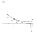
- FIG. 3 is a diagram for explaining a static traveling route.
- 1 indicates a static track boundary on the left side with respect to the traveling direction of the own vehicle
- 2 indicates a static track boundary on the right side with respect to the traveling direction of the own vehicle
- 3 indicates a static traveling route generator.
- the static travel path generated by 182 is shown.
- the static travel route generation unit 182 recognizes the static track boundary 1 on the left side and the static track boundary 2 on the right side from the information of the own lane boundary input from the own lane boundary generation unit 181.
- the static track boundary 1 and the static track boundary 2 are track boundaries that reflect the road shape and road width stored in the map information. That is, the static track boundary 1 and the static track boundary 2 are track boundaries defined as map information.
- the static travel route generation unit 182 sets the route length of the static travel route. For example, the static travel route generation unit 182 sets the route length of the static travel route so that at least two corners are included on the road on which the own vehicle travels. Further, for example, the static travel route generation unit 182 sets the route length of the static travel route so as to include a straight section of a predetermined distance or more after the corner.
- the straight section is a section of a straight road whose curvature is equal to or less than a preset threshold value and greater than or equal to a preset distance.
- the static travel route generation unit 182 sets the route length of the static travel route 3 to about 240 m.
- the static travel route generation unit 182 generates a static travel route by using, for example, an evaluation function which is a quadratic convex function and Newton's method.
- the static travel route generation unit 182 uses an evaluation function satisfying the following equations (1) and (2) as a static travel route.
- J indicates an evaluation function (static travel route), and u (i) indicates the moving distance of the own vehicle from the track center line at each point.
- the distance, y sr indicates the distance between the static track boundary on the right side and the track centerline.
- k ⁇ is a weighting coefficient indicating the magnitude of the influence of the element that relaxes the curvature on the first dynamic traveling path described later.
- the static travel route generation unit 182 calculates u (i) satisfying the above equation (2), and statically travels the evaluation function J when the calculated u (i) is substituted into the above equation (1). Let it be a route.
- the track center line in the above formula (1) is a center line extending along the center of the left and right static track boundaries.
- the potential field potential energy
- the starting point at which the potential energy becomes 0 V at the track center line is calculated using the Newton method.
- An example is a method of searching for a contour line having a potential energy of 0 V using RK4 (Runge-Kutta method).
- the method of generating the track center line is an example, and other methods may be used.
- the function of the travelable area generation unit 183 will be described.
- the travelable area generation unit 183 generates a travelable area as a travelable area with respect to the surrounding environment of the vehicle.
- Information on the relative distance between the own vehicle and the object, the direction in which the object is located with respect to the own vehicle, and the relative speed of the object with respect to the own vehicle is input to the travelable area generation unit 183 from the distance measuring sensor 140. Will be done. Further, the travelable area generation unit 183 receives information on a captured image in which an object existing in the vicinity of the own vehicle moves from the camera 150. Based on these input information, the travelable area generation unit 183 recognizes the dynamic track boundary indicating the boundary between the track of the own vehicle and the rest. In the following description, various information input from the distance measuring sensor 140 and the camera 150 will be referred to as dynamic track boundary information. In other words, the travelable area generation unit 183 acquires information on the dynamic track boundary from the distance measuring sensor 140 and the camera 150 that detect the surrounding environment of the own vehicle. The dynamic track boundary information may be only the information input from the distance measuring sensor 140.
- the dynamic track boundary is composed of information on the object detected by the distance measuring sensor 140 and / or the object imaged by the camera 150.
- the dynamic track boundary is a track boundary according to the surrounding environment of the own vehicle.
- Examples of dynamic track boundaries include road markings, road structures, and obstacles.
- Examples of the dynamic track boundary of the road marking include a lane boundary line and a center line.
- the dynamic track boundary of the road structure includes, for example, a median strip, a guardrail, a curb, a tunnel, or a side wall of a highway.
- Examples of the dynamic track boundary of the obstacle include other vehicles, motorcycles, and bicycles.
- the travelable area generation unit 183 can distinguish the dynamic track boundary into the first dynamic track boundary and the second dynamic track boundary according to the type of the dynamic track boundary.
- the first dynamic track boundary is a dynamic track boundary marked on the road surface. Examples of the first dynamic track boundary include a lane boundary line and a center line.
- the second dynamic track boundary is a dynamic track boundary of an object (obstacle) existing around the road structure and / or the own vehicle. Examples of the second dynamic track boundary include a median strip, a guardrail, a curb, another vehicle, a motorcycle, a bicycle, and the like.
- the travelable area generation unit 183 generates a travelable area of the own vehicle based on the dynamic track boundary information. For example, when the lane in which the own vehicle travels is defined by the left and right lane boundaries (white lines), the travelable area generation unit 183 recognizes the left white line and the right white line as dynamic lane boundaries. Then, the travelable area generation unit 183 generates a region located between the white line on the left side and the white line on the right side as the travelable area of the own vehicle. Further, in the above example, when the parked vehicle exists on the left front side with respect to the traveling direction of the own vehicle, the travelable area generation unit 183 dynamically draws the side surface of the parked vehicle and the white line on the right side detected by the distance measuring sensor 140.
- the travelable area generation unit 183 Recognize as a track boundary. Then, the travelable area generation unit 183 generates an area excluding the area occupied by the parked vehicle as a travelable area in which the own vehicle can overtake the parked vehicle. In this way, the dynamic track boundary is different from the static track boundary in that it changes according to the surrounding environment of the own vehicle. Further, since the dynamic track boundary is based on the information detected by the ranging sensor 140 whose detection range is limited and / or the information captured by the camera 150 whose imaging range is limited, the information on the dynamic track boundary is obtained. It is limited to the information of the track boundary existing in the detection range of the distance measuring sensor 140 and / or the information of the track boundary existing in the imaging range of the camera 150.
- the static track boundary information includes information on the track boundary that exists outside the detection range of the distance measuring sensor 140 and / or the imaging range of the camera 150. Including.
- the travelable area information generated by the travelable area generation unit 183 is output to the dynamic travel path generation unit 184.
- the dynamic travel route generation unit 184 generates a travel route corresponding to the surrounding environment of the own vehicle as a dynamic travel route.
- the dynamic travel route is a travel route different from the static travel route, and is a travel route that reflects the current surrounding environment of the own vehicle.
- the dynamic travel route is a travel route for minimizing the risk that occurs depending on the surrounding environment of the own vehicle. Examples of such a risk include a risk that the own vehicle runs outside the lane boundary line, a risk that the own vehicle approaches an obstacle existing on the road, and the like. As shown in FIG.
- the dynamic travel route generation unit 184 is input with static travel route information from the static travel route generation unit 182 and information on the travelable area from the travelable area generation unit 183. To.
- the dynamic travel route generation unit 184 generates a dynamic travel route using various input information, and outputs the dynamic travel route information to the route coupling unit 185.
- FIG. 4 is a diagram for explaining various information used for generating a dynamic traveling route.
- the various information shown in FIG. 4 is information input to the dynamic travel path generation unit 184 when the own vehicle is traveling at the position P in FIG.
- the x-axis and y-axis shown in FIG. 4 correspond to the x-axis and y-axis shown in FIG.
- 3a corresponds to the static travel path 3 shown in FIG.
- the static travel route 3a is a route in which the static travel route 3 is corrected by the dynamic travel route generation unit 184. Further, in FIG.
- FIG. 4 is white lines (first dynamic lane boundary) that define the lane in which the own vehicle travels, and 6 and 7 are road structures such as shoulders or guardrails (second dynamic lane boundary), 8 Indicates a parked vehicle (second dynamic track boundary).
- the dynamic track boundaries 4 to 8 are displayed as point data detected by the distance measuring sensor 140, but the display form of the data is not limited to the point data.
- FIG. 4 shows the dynamic track boundary itself instead of the travelable area, the dynamic travel path generation unit 184 may generate a dynamic travel path by using the information of the travelable area. .. Further, the correction of the static traveling route will be described later.
- the dynamic travel path generation unit 184 recognizes the dynamic track boundary 4 to the dynamic track boundary 8 from the information input from the distance measuring sensor 140 and the camera 150.
- the dynamic track boundary 4 to the dynamic track boundary 8 are information indicating the surrounding environment of the own vehicle when the own vehicle travels at the position P shown in FIG.
- the dynamic travel route generation unit 184 sets the route length of the dynamic travel route.
- the dynamic travel route generation unit 184 sets the route length of the dynamic travel route to be shorter than the route length of the static travel route shown in FIG. This is based on the viewpoint that the dynamic track boundary 4 to the dynamic track boundary 8 shown in FIG. 4 change with time because the surrounding environment of the own vehicle changes with time.
- the dynamic travel path generation unit 184 sets the dynamic travel path so that the entire dynamic travel path is included in the smaller of the detectable range of the distance measuring sensor 140 and the imageable range of the camera 150.
- the route length of In the example of FIG. 4, the dynamic travel route generation unit 184 sets the route length of the dynamic travel route to 40 m.
- the dynamic travel route generation unit 184 generates a dynamic travel route by using, for example, an evaluation function which is a quadratic convex function and Newton's method.
- the dynamic travel route generation unit 184 uses an evaluation function satisfying the following equations (3) and (4) as the dynamic travel route.
- J indicates an evaluation function (dynamic travel path)
- u (i) indicates the moving distance of the own vehicle from the track center line at each point.
- the distance between the line and y sr indicates the distance between the first dynamic track boundary on the right side and the track center line.
- y hl is the second dynamic track boundary and the track center on the left side.
- the distance between the line and yhr indicates the distance between the second dynamic track boundary on the right side and the track centerline.
- y hp is the distance between the track center line and the static traveling route. Is shown.
- k ⁇ is a weighting coefficient indicating the magnitude of the influence of the element that relaxes the curvature on the first dynamic traveling path.
- the weighting coefficient a s , the weighting coefficient a h , and the weighting coefficient a lp have a relationship of "weighting coefficient a h > weighting coefficient a l > weighting coefficient a lp ". It is preset by the control device 180 so as to satisfy.
- the dynamic travel route generation unit 184 calculates u (i) satisfying the above equation (4), and dynamically travels the evaluation function J when the calculated u (i) is substituted into the above equation (3). Route.
- the above-mentioned explanation is used.
- the route coupling unit 185 generates a target traveling route of the own vehicle by combining the dynamic traveling route and the static traveling route.
- the target travel route of the own vehicle is a travel route for the own vehicle to travel smoothly while responding to the surrounding environment.
- the target travel route is a travel route that extends from the current position of the own vehicle along the dynamic travel route and extends along the static travel route after the end point of the dynamic travel route.
- the target travel route is a travel route that is a combination of a dynamic travel route and a static travel route.
- the static travel route generation unit 182 inputs the static travel route information to the route coupling unit 185
- the dynamic travel route generation unit 184 inputs the dynamic travel route information.
- the route coupling unit 185 combines the static travel route and the dynamic travel route so that the end point of the dynamic travel route (also referred to as the end of the dynamic travel route) is located on the static travel route.
- the route (target traveling route) coupled by the route coupling unit 185 is output to the route following unit 186.
- FIG. 5 is a diagram for explaining a method of combining a static traveling route and a dynamic traveling route.
- 3a corresponds to the static travel path 3 shown in FIG.
- the static travel route 3a is a route in which the static travel route 3 is corrected by the route coupling portion 185.
- 10 indicates a dynamic traveling route
- 11 indicates a parked vehicle (obstacle). The correction of the static travel route will be described later.
- the route connecting portion 185 connects the dynamic traveling route 10 and the static traveling route 3a so that the end point 10a of the dynamic traveling route 10 is located on the static traveling route 3a.
- a target traveling route is generated in which the dynamic traveling route 10 for avoiding the obstacle 11 and the static traveling route 3a for the own vehicle to smoothly travel on the curve are combined.
- the route following unit 186 executes automatic driving control that automatically performs all or part of the traveling of the own vehicle so that the own vehicle travels on the target traveling route.
- the path following unit 186 calculates a control command value for following the target path, and outputs the control command value to the drive mechanism 170.
- Examples of the control command value include a steering angle command value which is a command value for controlling the steering angle of the own vehicle.
- the path following unit 186 can also execute the path following process (for example, feedback control) known at the time of filing the application.
- FIG. 6 is a diagram for explaining an example of a method of calculating a control command value.
- 12 is a target travel path
- 13 is a gaze point (x front , y e ) on the target travel path set by the forward gaze model
- 14 is a circle tangent to the origin O and the gaze point 13.
- the x-axis and y-axis shown in FIG. 6 correspond to the x-axis and y-axis shown in FIG.
- the forward gaze model is a model of a forward point that the driver gazes at when driving, and is a predetermined model. Further, in the example of FIG. 6, it is assumed that the own vehicle V is located at the origin O.
- the path following unit 186 calculates the curvature of the circle 14 by using the following equation (7) in order to travel along the target traveling path 12. Then, the path following unit 186 calculates a steering angle command value for traveling the own vehicle along the target traveling path 12 based on the curvature of the circle 14 shown in FIG.
- FIG. 7 is a diagram for explaining the calculation cycle and the calculation load of the processor in each process of the control device 180. Since FIG. 7 corresponds to FIG. 2, the above-mentioned description is used for the explanation of the function of each block shown in FIG. 7.
- the arithmetic cycle (also referred to as arithmetic processing time) of the processor is divided into three, high speed, medium speed, and low speed, according to the block of the control device 180.
- the arithmetic cycle of the processor in the static travel route generation process is longer than the processor arithmetic cycle in the dynamic travel path generation process and the processor arithmetic cycle in the control command value calculation process.
- the calculation cycle of the processor in the process of generating the dynamic travel path is longer than the calculation cycle of the processor in the process of calculating the control command value.
- the arithmetic load of the processor is divided into three, a high load, a medium load, and a low load, depending on the block of the control device 180.
- the computing load of the processor in the static traveling route generation processing is higher than the computing load of the processor in the dynamic traveling route generation processing and the computing load of the processor in the calculation processing of the control command value.
- the computing load of the processor in the processing of generating the dynamic travel route is higher than the computing load of the processor in the processing of calculating the control command value.
- the processor executes processing for blocks related to static travel routes (own lane boundary generation unit 181 and static travel route generation unit 182) at a low calculation cycle. It is preferable to reduce the update frequency of a static travel route having a relatively long route length while reflecting the map information having a low update frequency.
- the processor for example, executes a process related to a static traveling path in a calculation cycle of 2 Hz. On the other hand, since each process requires a huge amount of data called map information, the computing load of the processor becomes high.
- the processor executes processing on the blocks related to the dynamic travel path (travelable area generation unit 183, dynamic travel route generation unit 184, and route coupling unit 185) in a medium-speed arithmetic cycle. .. It is necessary to update according to the surrounding environment of the own vehicle, and it is preferable to increase the update frequency of the dynamic traveling route having a relatively short route length.
- the processor executes processing related to the dynamic travel path in, for example, a calculation cycle of 10 Hz.
- the calculation load of the processor becomes slightly high.
- the processor executes processing of the block related to path tracking (path tracking unit 186) in a high-speed calculation cycle.
- path tracking unit 186 In the route tracking process that requires feedback control, it is preferable to increase the update frequency.
- the processor executes processing related to path tracking in, for example, a calculation cycle of 100 Hz.
- the computing load of the processor is small.
- the present embodiment by allocating the calculation cycle according to the calculation load to each block, for example, it is possible to prevent the static traveling route having a high calculation load from being updated frequently, and the control device.
- the computing load of the entire 180 can be reduced.
- FIG. 8A shows a block diagram for explaining the correction process for the static traveling route
- FIG. 8B shows the static traveling route in each block shown in FIG. 8A.
- the dynamic travel route generation unit 184 corrects the static travel route by reflecting the travel distance traveled by the own vehicle during the cycle in which the dynamic travel route is generated in the static travel route. Specifically, first, the dynamic travel route generation unit 184 estimates the position of the own vehicle on the map based on the map information and the detection result of the distance measuring sensor 140. Then, as shown in FIG. 8A, the dynamic travel route generation unit 184 sets the coordinates that define the static travel route based on the estimated position of the own vehicle on the map, with the coordinates centered on the position of the own vehicle. Execute the coordinate conversion process to convert the system to the coordinate system centered on the position on the map. The coordinate system centered on the position of the own vehicle is also called the vehicle coordinate system. A coordinate system centered on a position on a map is also called a static coordinate system.
- the coordinate transformation from the vehicle coordinate system to the stationary coordinate system corresponds to the coordinate transformation A.
- the static travel path R0 is defined by the vehicle coordinate system and is updated by the arithmetic cycle (low speed) of the processor in the static travel route generation process.
- the dynamic travel route generation unit 184 executes coordinate conversion processing from the vehicle coordinate system to the static coordinate system for the static travel route, and in the subsequent processing, the calculation of the processor in the dynamic generation processing of the static travel route. Process at a cycle (medium speed). As a result, the update frequency of the static travel route is changed from the arithmetic cycle (low speed) of the processor in the static travel route generation process to the processor arithmetic cycle (medium speed) in the dynamic travel route generation process. In Figure 8B, it is defined in the stationary coordinate system, and the static driving route that is updated by the calculation cycle of the processor in the generation process of the dynamic travel path, indicated by the static traveling path R 1.
- the dynamic travel route generation unit 184 executes a coordinate conversion process for converting the coordinates defining the static travel route from the static coordinate system to the vehicle coordinate system based on the estimated position of the own vehicle on the map.
- Figure 8B is defined by the vehicle coordinate system, and the static driving route that is updated by the calculation cycle of the processor in the generation process of the dynamic travel path, indicated by the static traveling path R 2.
- the static travel route R 2 is a travel route in which the travel distance of the own vehicle is reflected with respect to the static travel route R 0 .
- FIG. 9 is a block diagram showing a flow of control processing according to the present embodiment.
- the travel control process described below is executed by the control device 180. Further, the travel control process described below starts when the ignition switch or the power switch is turned on, and is repeatedly executed at a predetermined cycle (for example, every 10 milliseconds) until the ignition switch or the power switch is turned off. Will be done. Further, the calculation cycle of the processor in each step shown in FIG. 9 satisfies the relationship of the calculation cycle of the processor in each block shown in FIG. 7.
- step S1 the control device 180 generates the own lane boundary.
- the control device 180 acquires the current position information of the own vehicle from the own vehicle position detection device 110, the static track boundary information from the map database 120, and the action plan information from the navigation system. Based on the input information, the control device 180 generates a own lane boundary indicating a boundary between the own lane and the rest.
- step S2 the control device 180 generates a static traveling route based on the information of the own lane boundary generated in step S1.
- the control device 180 sets the path length of the static traveling route.
- the control device 180 sets the route length of the static traveling route so as to include at least two corners on the road on which the own vehicle travels.
- the control device 180 sets the route length of the static traveling route so as to include a straight section of a predetermined distance or more.
- the control device 180 generates, for example, a travel path that minimizes the change in lateral acceleration applied to the own vehicle when the vehicle travels on the track on the map as a static travel route.
- the control device 180 uses the evaluation function, which is a quadratic convex function, and Newton's method to generate a static travel path.
- step S3 the control device 180 generates a travelable area.
- the control device 180 acquires the information of the dynamic track boundary from the distance measuring sensor 140 and the camera 150, and recognizes the dynamic track boundary.
- the control device 180 generates a region defined by the dynamic track boundary as a travelable region in which the own vehicle can travel.
- step S4 the control device 180 generates a dynamic travel path.
- the control device 180 generates a travel route corresponding to the surrounding environment of the own vehicle as a dynamic travel route based on the static travel route generated in step S2 and the travelable area generated in step S3. ..
- the control device 180 executes correction processing for static traveling routes having different update frequencies, and generates a dynamic traveling route using the corrected static traveling route.
- step S5 the control device 180 generates a target travel route by combining the dynamic travel route and the static travel route.
- the control device 180 sets a target travel route composed of a dynamic travel route and a static travel route based on the static travel route generated in step S2 and the dynamic travel route generated in step S4. Generate.
- the control device 180 combines the dynamic travel path and the static travel path so that the end point of the dynamic travel path is located on the static travel path.
- step S6 the control device 180 generates a control command value for traveling the own vehicle along the target travel route.
- the control device 180 generates a control command value (for example, a steering angle command value) based on the target travel path generated in step S5.
- the control device 180 ends the control process shown in FIG.
- the control device 180 acquires information on the static track boundary, which is the boundary between the track of the own vehicle and other than the track, from the map database 120 that stores the map information, and the own vehicle.
- Information on a dynamic track boundary different from the static track boundary is acquired from the distance measuring sensor 140 and the camera 150 that detect the surrounding conditions of the vehicle.
- the control device 180 generates a static traveling route as a traveling route on which the own vehicle can travel based on the information on the static traveling route boundary, and statically based on the information on the static traveling route and the dynamic driving route boundary.
- a dynamic driving route is generated as a driving route that is shorter than the traveling route and corresponds to the surrounding environment of the own vehicle.
- the control device 180 causes the own vehicle to travel along a target travel route including a static travel route and a dynamic travel route. Since the dynamic driving route is based on the static driving route for smoothly traveling the own vehicle while corresponding to the surrounding environment of the own vehicle, it is possible to make a driving plan that balances the correspondence with the surrounding environment and smooth driving. it can.
- the information on the static track boundary since the information on the static track boundary also includes information on a position far away from the own vehicle, it is used to generate a long-term smooth route in consideration of the following driving conditions. There is an advantage that can be done.
- the information on the static track boundary does not include information on the dynamic surrounding conditions, and is unsuitable for traveling according to the surrounding dynamic environment. Therefore, in order to supplement the dynamic surrounding conditions, in the present embodiment, a dynamic traveling route corresponding to the surrounding environment of the own vehicle is generated based on the information of the dynamic driving path boundary.
- the dynamic travel route is generated not only by the information of the dynamic route boundary but also by using the static travel route characterized by smoothness. As a result, it is possible to realize driving that matches the surrounding dynamic environment, which was difficult with a traveling route that uses only static track boundary information.
- the information on the dynamic track boundary includes information on the dynamic surrounding conditions, generates a travel route based on the information on the dynamic track boundary, and travels on the travel route to move the surroundings. You will be able to drive according to the environment.
- the information on the dynamic track boundary is limited to the detection range of the sensor of the own vehicle, the information on the position far away from the own vehicle is acquired, and the traveling route considering the situation of the position far away from the own vehicle. It is not suitable for generating.
- not only the dynamic track boundary but also the static travel route generated by using the static track boundary information including the information outside the detection range of the sensor that detects the dynamic track boundary is considered. To do. As a result, in the present embodiment, it is possible to generate a traveling route that takes into account the situation outside the detection range of the sensor, that is, the situation at a position far away from the own vehicle.
- a dynamic traveling route shorter than the static traveling route is generated.
- a long-term travel route By generating a long-term travel route, it can be used to generate a long-term smooth route in consideration of the following travel conditions.
- the calculation load is high because the long-term route is calculated.
- it is also expensive to calculate the travel route by the same route length as the static travel route based on the information of the dynamic route boundary. Therefore, in the present embodiment, by generating a dynamic travel route shorter than the static travel route, it is possible to suppress the calculation load for calculating the dynamic travel route.
- the static track boundary information includes information outside the detection range of the sensor that detects the dynamic track boundary, and the static travel route is outside the detection range of the sensor that detects the dynamic track boundary. Generated with information.
- data stored in a memory or data already stored in the cloud is used to generate a static travel route using information on a static route boundary. Therefore, information outside the detection range of the sensor can be stably acquired, and a long-term static traveling route can be generated.
- the information on the dynamic track boundary is based on the information detected by the sensor, the information is limited to the information within the detection range of the sensor.
- the dynamic track boundary information includes information in the vicinity of the own vehicle and not included in the static track boundary information (for example, dynamic object information), the dynamic track boundary information is acquired. By generating a dynamic travel route based on the dynamic route boundary information, it is possible to respond according to the surrounding environment.
- the static lane boundary information includes information on the lane in which the own vehicle travels and information on the lane in which the own vehicle is scheduled to travel different from the lane
- the static travel route includes information on the lane in which the own vehicle travels. It is generated using the information of the lane to be driven and the information of the lane in which the own vehicle different from the lane is scheduled to travel.
- the own vehicle merges into the merging lane or when the own vehicle turns left or right, not only the lane in which the own vehicle is currently traveling, but also the lane to which the own vehicle is going to travel or the destination where the vehicle turns left or right. Since it is possible to generate a static driving route in consideration of the situation of the lane of the vehicle, a smoother driving route can be generated.
- control device 180 calculates a control command value for traveling the own vehicle along the target traveling route, and controls the own vehicle based on the control command value. As a result, the own vehicle can be smoothly driven while being compatible with the surrounding environment.
- control device 180 generates a target travel route by combining the dynamic travel route and the static travel route so that the end point of the dynamic travel route is located on the static travel route. To do. As a result, even if the traveling paths generated based on different information are combined, it is possible to suppress the occurrence of a discontinuity of curvature at the connecting portion. As a result, the own vehicle can be smoothly traveled along the target traveling route.
- the arithmetic cycle of the processor in the static travel route generation process is longer than the processor arithmetic cycle in the dynamic travel route generation process.
- the dynamic traveling route can be updated in a short cycle according to the dynamically changing situation around the own vehicle, so that the own vehicle can travel in accordance with the surrounding environment.
- the information on the static track boundary rarely changes dynamically, and the information is stable. Therefore, even if the static travel route is updated frequently, the shape does not change significantly.
- the position of the own vehicle is changed from the position where the static traveling route was calculated last time. It's changing. Therefore, it is also necessary to generate a static traveling route starting from the position of the own vehicle after movement (also referred to as a new position). As described above, even if the static travel route is not calculated frequently, it is necessary to generate the static travel route starting from the position of the own vehicle after the movement. Therefore, in the present embodiment, the static travel route is generated.
- the calculation cycle of the processor in the generation process of is longer than the calculation cycle of the processor in the generation process of the dynamic travel path. As a result, it becomes possible to generate a smooth static traveling route, and thus a dynamic traveling route, while suppressing the calculation load for generating the static traveling route.
- the calculation cycle of the processor in the static travel route generation process is longer than the calculation cycle of the processor in the calculation process of the control command value.
- the frequency of updating the control command value is increased, so that the followability to the generated traveling path can be improved and the follow-up control can be executed.
- the stability of follow-up control can be improved.
- the arithmetic cycle of the processor in the static travel route generation process is longer than the processor arithmetic cycle in the dynamic travel route generation process, and in addition, the processor arithmetic cycle in the static travel route generation process is the control command value. The same effect can be obtained even if the calculation cycle is longer than the calculation cycle of the processor.
- the calculation cycle of the processor in the process of generating the dynamic travel route is longer than the calculation cycle of the processor in the process of calculating the control command value.
- the frequency of updating the control command value is increased, so that the followability to the generated traveling path can be improved and the follow-up control can be executed.
- the stability of follow-up control can be improved.
- the arithmetic cycle of the processor in the static travel route generation process is longer than the processor arithmetic cycle in the dynamic travel route generation process, and in addition, the processor arithmetic cycle in the dynamic travel route generation process is the control command value. The same effect can be obtained even if the calculation cycle is longer than the calculation cycle of the processor.
- the control device 180 in the process of generating the dynamic travel route, the control device 180 reflects the travel distance traveled by the own vehicle during the cycle in which the dynamic travel route is generated in the static travel route. Then, the static driving route is corrected. As a result, even if the update frequency of the static travel route is lower than the update frequency of the dynamic travel route, the dynamic travel route is set based on the information of the static travel route corresponding to the current position of the own vehicle. Can be generated. As a result, the stability of the follow-up control along the target travel path can be improved.
- the control device 180 estimates the position of the own vehicle on the map based on the map information and the detection result of the distance measuring sensor 140, and in the correction processing of the static traveling route, the own vehicle on the map. After executing the coordinate conversion process that converts the coordinates that define the static travel route from the coordinate system centered on the position of the own vehicle to the coordinate system centered on the position on the map based on the position of The static travel path is corrected by the calculation cycle of the processor in the travel route generation process. Since the correction processing of the static traveling route is executed based on the highly accurate map information, the correction accuracy of the static traveling route can be improved.
- control device 180 generates a runway with the minimum change in curvature as a static runway. As a result, the own vehicle can run smoothly regardless of the shape of the road.
- the route length of the static travel route is longer than the route length of the dynamic travel route.
- control device 180 sets the route length of the static traveling route so as to include at least two corners.
- the static traveling path includes the start point and the end point of the corner, it is possible to suppress the occurrence of the discontinuity of curvature at the start point and the end point of the corner.
- the own vehicle can be smoothly traveled along the target traveling route.
- control device 180 sets the route length of the static traveling route so as to include a section of a straight road having a predetermined distance or more after the corner. As a result, it is possible to suppress the occurrence of a discontinuity point of curvature in the section between the corner and the straight road. As a result, the own vehicle can be smoothly traveled along the target traveling route.
- control device 180 sets the path length of the dynamic travel path so that the dynamic travel path is included in the detection range of the distance measuring sensor 140.
- the detection result of the distance measuring sensor 140 can be used in generating the dynamic traveling path.
- the control device 180 recognizes the dynamic track boundary which is a road marking as the first dynamic track boundary, and secondly moves the dynamic track boundary which is an obstacle existing around the own vehicle. Recognize as a target track boundary.
- the degree of influence of the first dynamic track boundary on the dynamic travel path and the degree of influence of the second dynamic track boundary on the dynamic travel path can be changed.
- control device 180 weighting factors a h, using a small relationship in the order of weighting coefficients a s and the weighting coefficients a lp, to generate dynamic driving route.
- a dynamic traveling route for avoiding the obstacle can be generated.
- a dynamic traveling route so as not to cross the white line.
- the route following unit 186 may execute the correction processing of the target traveling route. That is, in the control command value calculation process, the control device 180 corrects the target travel route by reflecting the travel distance traveled by the own vehicle during the cycle in which the control command value is calculated in the target travel route. May be good. As a result, even if the update frequency of the target travel route is lower than the update frequency of the control command value, the control command value can be calculated based on the information of the target travel route corresponding to the current position of the own vehicle. it can. As a result, the stability of the follow-up control along the target travel path can be improved.
- control device 180 estimates the position of the own vehicle on the map based on the map information and the detection result of the distance measuring sensor 140, and in the correction processing of the target travel route, the target travel is based on the position of the own vehicle on the map.
- the processor's calculation in the calculation process of the control command value After executing the coordinate conversion process that converts the coordinates that define the route from the coordinate system centered on the position of the own vehicle to the coordinate system centered on the position on the map, the processor's calculation in the calculation process of the control command value.
- the target travel route may be corrected by the cycle. Since the correction process of the target travel route is executed based on the highly accurate map information, the correction accuracy of the target travel route can be improved.
- the dynamic travel route generation unit 184 dynamically sets a travel route that minimizes the change in lateral acceleration applied to the vehicle when the vehicle travels on the route on the map based on the information of the dynamic route boundary. It may be generated as a traveling route. As a result, for example, when an obstacle exists around the own vehicle, the obstacle can be smoothly avoided (for example, passing through).
- the own vehicle travels at the combination point of the dynamic travel route and the static travel route, the lateral acceleration applied to the own vehicle is suppressed, and the travel of the own vehicle is smoothed from the dynamic travel route to the static travel route. You can make a transition. Similarly, the traveling of the own vehicle can be smoothly transitioned from the static traveling route to the dynamic traveling route. As a result, it is possible to suppress the discomfort given to the occupants of the own vehicle due to the difference in the traveling route.
- Driving support device 110 ... Own vehicle position detection device 120 ... Map database 130 ... Vehicle speed sensor 140 ... Distance measurement sensor 150 ... Camera 160 ... Input device 170 ... Drive mechanism 180 ... Control device (processor) 190 ... Yaw rate sensor
Landscapes
- Engineering & Computer Science (AREA)
- Automation & Control Theory (AREA)
- Human Computer Interaction (AREA)
- Transportation (AREA)
- Mechanical Engineering (AREA)
- Traffic Control Systems (AREA)
- Control Of Driving Devices And Active Controlling Of Vehicle (AREA)
Priority Applications (5)
| Application Number | Priority Date | Filing Date | Title |
|---|---|---|---|
| US17/618,070 US12214803B2 (en) | 2019-06-14 | 2019-06-14 | Travel assistance method and travel assistance device |
| CN201980097468.8A CN114287025B (zh) | 2019-06-14 | 2019-06-14 | 行驶辅助方法及行驶辅助装置 |
| EP19932255.3A EP3985641B1 (en) | 2019-06-14 | 2019-06-14 | Travel assistance method and travel assistance device |
| JP2021525393A JP7226545B2 (ja) | 2019-06-14 | 2019-06-14 | 走行支援方法および走行支援装置 |
| PCT/IB2019/000634 WO2020249995A1 (ja) | 2019-06-14 | 2019-06-14 | 走行支援方法および走行支援装置 |
Applications Claiming Priority (1)
| Application Number | Priority Date | Filing Date | Title |
|---|---|---|---|
| PCT/IB2019/000634 WO2020249995A1 (ja) | 2019-06-14 | 2019-06-14 | 走行支援方法および走行支援装置 |
Publications (1)
| Publication Number | Publication Date |
|---|---|
| WO2020249995A1 true WO2020249995A1 (ja) | 2020-12-17 |
Family
ID=73780694
Family Applications (1)
| Application Number | Title | Priority Date | Filing Date |
|---|---|---|---|
| PCT/IB2019/000634 Ceased WO2020249995A1 (ja) | 2019-06-14 | 2019-06-14 | 走行支援方法および走行支援装置 |
Country Status (5)
| Country | Link |
|---|---|
| US (1) | US12214803B2 (https=) |
| EP (1) | EP3985641B1 (https=) |
| JP (1) | JP7226545B2 (https=) |
| CN (1) | CN114287025B (https=) |
| WO (1) | WO2020249995A1 (https=) |
Cited By (3)
| Publication number | Priority date | Publication date | Assignee | Title |
|---|---|---|---|---|
| JP2023007914A (ja) * | 2021-07-02 | 2023-01-19 | 株式会社デンソー | 推定システム、推定装置、推定方法、推定プログラム |
| EP4438429A4 (en) * | 2021-11-24 | 2025-10-15 | Shanghai Horizon Intelligent Automotive Tech Co Ltd | VEHICLE LANE CHANGE CONTROL METHOD AND APPARATUS, ELECTRONIC DEVICE, AND STORAGE MEDIUM |
| WO2026069625A1 (ja) * | 2024-09-27 | 2026-04-02 | 本田技研工業株式会社 | 移動体制御システム、移動体の制御方法、プログラム、および、移動体 |
Families Citing this family (2)
| Publication number | Priority date | Publication date | Assignee | Title |
|---|---|---|---|---|
| WO2020249995A1 (ja) * | 2019-06-14 | 2020-12-17 | 日産自動車株式会社 | 走行支援方法および走行支援装置 |
| JP7347522B2 (ja) * | 2019-09-27 | 2023-09-20 | 株式会社アイシン | 運転支援装置及びコンピュータプログラム |
Citations (6)
| Publication number | Priority date | Publication date | Assignee | Title |
|---|---|---|---|---|
| JP2005164379A (ja) * | 2003-12-02 | 2005-06-23 | Mitsubishi Electric Corp | 移動体補助案内装置 |
| WO2012014280A1 (ja) | 2010-07-27 | 2012-02-02 | トヨタ自動車株式会社 | 運転支援装置 |
| WO2016189727A1 (ja) * | 2015-05-28 | 2016-12-01 | 日産自動車株式会社 | 走行制御装置及び方法 |
| JP2017016645A (ja) * | 2015-06-29 | 2017-01-19 | 三菱電機株式会社 | 半自律車両、及び、半自律車両を制御する方法 |
| WO2017168662A1 (ja) * | 2016-03-30 | 2017-10-05 | 三菱電機株式会社 | 走行計画生成装置、走行計画生成方法及び走行計画生成プログラム |
| JP2017193189A (ja) * | 2016-04-18 | 2017-10-26 | 日立オートモティブシステムズ株式会社 | 走行制御装置 |
Family Cites Families (37)
| Publication number | Priority date | Publication date | Assignee | Title |
|---|---|---|---|---|
| KR20000014637A (ko) * | 1998-08-22 | 2000-03-15 | 윤종용 | 차량항법 시스템에서의 신규 도로정보 생성조합장치 |
| JP3956838B2 (ja) * | 2002-11-22 | 2007-08-08 | アイシン・エィ・ダブリュ株式会社 | 情報表示システム、情報表示方法及びそのプログラム |
| US7734387B1 (en) * | 2006-03-31 | 2010-06-08 | Rockwell Collins, Inc. | Motion planner for unmanned ground vehicles traversing at high speeds in partially known environments |
| GB201219742D0 (en) * | 2012-11-02 | 2012-12-12 | Tom Tom Int Bv | Methods and systems for generating a horizon for use in an advanced driver assistance system (adas) |
| JP6396645B2 (ja) * | 2013-07-11 | 2018-09-26 | 株式会社Soken | 走行経路生成装置 |
| JP6301713B2 (ja) * | 2013-08-12 | 2018-03-28 | 株式会社Soken | 走行経路生成装置 |
| US9199668B2 (en) * | 2013-10-28 | 2015-12-01 | GM Global Technology Operations LLC | Path planning for evasive steering maneuver employing a virtual potential field technique |
| KR101581286B1 (ko) * | 2014-01-17 | 2015-12-31 | 전남대학교산학협력단 | 무인운전차량의 자율 주행을 위한 경로 추종 시스템 및 방법 |
| US10747234B1 (en) * | 2016-01-22 | 2020-08-18 | State Farm Mutual Automobile Insurance Company | Method and system for enhancing the functionality of a vehicle |
| US11008009B2 (en) * | 2016-10-03 | 2021-05-18 | Honda Motor Co., Ltd. | Vehicle control device |
| WO2018066024A1 (ja) * | 2016-10-03 | 2018-04-12 | 本田技研工業株式会社 | 車両制御装置 |
| KR101916527B1 (ko) * | 2016-10-12 | 2018-11-07 | 국방과학연구소 | 무인차량의 자율주행 제어 방법 |
| US11142197B2 (en) * | 2016-10-18 | 2021-10-12 | Honda Motor Co., Ltd. | Vehicle control device |
| CN106873600A (zh) * | 2017-03-31 | 2017-06-20 | 深圳市靖洲科技有限公司 | 一种面向无人自行车的局部避障路径规划方法 |
| US12033194B2 (en) | 2017-06-15 | 2024-07-09 | Honda Motor Co., Ltd. | Ridesharing management device, ridesharing management method, and program |
| WO2019043832A1 (ja) * | 2017-08-30 | 2019-03-07 | 日産自動車株式会社 | 運転支援車両の走行制御方法及び走行制御装置 |
| JP6972793B2 (ja) * | 2017-09-04 | 2021-11-24 | 日産自動車株式会社 | 運転支援車両の走行制御方法及び走行制御装置 |
| US10754339B2 (en) * | 2017-09-11 | 2020-08-25 | Baidu Usa Llc | Dynamic programming and quadratic programming based decision and planning for autonomous driving vehicles |
| US20180004215A1 (en) * | 2017-09-15 | 2018-01-04 | GM Global Technology Operations LLC | Path planning of an autonomous vehicle for keep clear zones |
| US10571921B2 (en) | 2017-09-18 | 2020-02-25 | Baidu Usa Llc | Path optimization based on constrained smoothing spline for autonomous driving vehicles |
| JP6573222B2 (ja) * | 2017-10-24 | 2019-09-11 | マツダ株式会社 | 車両制御装置 |
| EP3740737A1 (en) * | 2018-04-03 | 2020-11-25 | Mobileye Vision Technologies Ltd. | Systems and methods for determining navigational parameters |
| EP3570206B1 (en) * | 2018-05-15 | 2023-12-06 | Aptiv Technologies Limited | A device and a method for searching for a lane on which a vehicle can drive |
| US12585275B1 (en) * | 2018-06-13 | 2026-03-24 | Nvidia Corporation | Loss scaling for neural networks |
| EP3915849B1 (en) * | 2019-01-22 | 2024-03-13 | NISSAN MOTOR Co., Ltd. | Vehicle travel control method and travel control device |
| CN109782766B (zh) * | 2019-01-25 | 2023-01-03 | 北京百度网讯科技有限公司 | 用于控制车辆行驶的方法和装置 |
| CN109737983B (zh) * | 2019-01-25 | 2022-02-22 | 北京百度网讯科技有限公司 | 用于生成行驶路径的方法和装置 |
| US11567514B2 (en) * | 2019-02-11 | 2023-01-31 | Tesla, Inc. | Autonomous and user controlled vehicle summon to a target |
| WO2020249995A1 (ja) * | 2019-06-14 | 2020-12-17 | 日産自動車株式会社 | 走行支援方法および走行支援装置 |
| US11480962B1 (en) * | 2019-06-28 | 2022-10-25 | Zoox, Inc. | Dynamic lane expansion |
| US11181927B2 (en) * | 2019-06-28 | 2021-11-23 | Nissan North America, Inc. | Automated learning system for improved pickup/dropoff maneuver |
| US11532167B2 (en) * | 2019-10-31 | 2022-12-20 | Zoox, Inc. | State machine for obstacle avoidance |
| CN115397709B (zh) * | 2020-04-06 | 2025-10-24 | 日产自动车株式会社 | 驾驶辅助方法及驾驶辅助装置 |
| WO2021258254A1 (en) * | 2020-06-22 | 2021-12-30 | Nvidia Corporation | Hybrid solution for stereo imaging |
| US12025465B2 (en) * | 2021-10-22 | 2024-07-02 | Zoox, Inc. | Drivable surface map for autonomous vehicle navigation |
| US12134399B2 (en) * | 2021-10-22 | 2024-11-05 | Zoox, Inc. | Drivable surface map for autonomous vehicle navigation |
| US20230222267A1 (en) * | 2022-01-11 | 2023-07-13 | Argo AI, LLC | Uncertainty Based Scenario Simulation Prioritization and Selection |
-
2019
- 2019-06-14 WO PCT/IB2019/000634 patent/WO2020249995A1/ja not_active Ceased
- 2019-06-14 US US17/618,070 patent/US12214803B2/en active Active
- 2019-06-14 JP JP2021525393A patent/JP7226545B2/ja active Active
- 2019-06-14 EP EP19932255.3A patent/EP3985641B1/en active Active
- 2019-06-14 CN CN201980097468.8A patent/CN114287025B/zh active Active
Patent Citations (6)
| Publication number | Priority date | Publication date | Assignee | Title |
|---|---|---|---|---|
| JP2005164379A (ja) * | 2003-12-02 | 2005-06-23 | Mitsubishi Electric Corp | 移動体補助案内装置 |
| WO2012014280A1 (ja) | 2010-07-27 | 2012-02-02 | トヨタ自動車株式会社 | 運転支援装置 |
| WO2016189727A1 (ja) * | 2015-05-28 | 2016-12-01 | 日産自動車株式会社 | 走行制御装置及び方法 |
| JP2017016645A (ja) * | 2015-06-29 | 2017-01-19 | 三菱電機株式会社 | 半自律車両、及び、半自律車両を制御する方法 |
| WO2017168662A1 (ja) * | 2016-03-30 | 2017-10-05 | 三菱電機株式会社 | 走行計画生成装置、走行計画生成方法及び走行計画生成プログラム |
| JP2017193189A (ja) * | 2016-04-18 | 2017-10-26 | 日立オートモティブシステムズ株式会社 | 走行制御装置 |
Cited By (4)
| Publication number | Priority date | Publication date | Assignee | Title |
|---|---|---|---|---|
| JP2023007914A (ja) * | 2021-07-02 | 2023-01-19 | 株式会社デンソー | 推定システム、推定装置、推定方法、推定プログラム |
| JP7647397B2 (ja) | 2021-07-02 | 2025-03-18 | 株式会社デンソー | 推定システム、推定装置、推定方法、推定プログラム |
| EP4438429A4 (en) * | 2021-11-24 | 2025-10-15 | Shanghai Horizon Intelligent Automotive Tech Co Ltd | VEHICLE LANE CHANGE CONTROL METHOD AND APPARATUS, ELECTRONIC DEVICE, AND STORAGE MEDIUM |
| WO2026069625A1 (ja) * | 2024-09-27 | 2026-04-02 | 本田技研工業株式会社 | 移動体制御システム、移動体の制御方法、プログラム、および、移動体 |
Also Published As
| Publication number | Publication date |
|---|---|
| US20220340168A1 (en) | 2022-10-27 |
| EP3985641A1 (en) | 2022-04-20 |
| CN114287025A (zh) | 2022-04-05 |
| EP3985641B1 (en) | 2023-10-04 |
| EP3985641A4 (en) | 2022-06-08 |
| JP7226545B2 (ja) | 2023-02-21 |
| CN114287025B (zh) | 2024-07-05 |
| JPWO2020249995A1 (https=) | 2020-12-17 |
| US12214803B2 (en) | 2025-02-04 |
Similar Documents
| Publication | Publication Date | Title |
|---|---|---|
| JP7052786B2 (ja) | 表示制御装置および表示制御プログラム | |
| EP3524934B1 (en) | Systems and methods for determining a projection of an obstacle trajectory onto a reference line of an autonomous vehicle | |
| JP6477903B2 (ja) | 走行制御方法および走行制御装置 | |
| JP7226545B2 (ja) | 走行支援方法および走行支援装置 | |
| JP7112658B2 (ja) | 車両運転支援システム及び方法 | |
| CN110053619A (zh) | 车辆控制装置 | |
| US11099017B2 (en) | Determining driving paths for autonomous driving vehicles based on offset points | |
| JPWO2020025991A1 (ja) | 走行軌跡補正方法、走行制御方法、及び走行軌跡補正装置 | |
| JP2018192954A (ja) | 運転支援装置 | |
| JP7416114B2 (ja) | 表示制御装置および表示制御プログラム | |
| JP7189087B2 (ja) | 走行支援方法および走行支援装置 | |
| JP2020163970A (ja) | 車両運転支援システム | |
| CN112009487A (zh) | 确定自动驾驶车辆的速度 | |
| CN112272805A (zh) | 连接两条平滑参考线的基于多点增强的拼接方法 | |
| CN111649751A (zh) | 一种用于参考线平滑的超自由缝合方法 | |
| WO2016103921A1 (ja) | 情報処理装置 | |
| WO2018211645A1 (ja) | 運転支援方法及び運転支援装置 | |
| JP2020163975A (ja) | 車両運転支援システム | |
| JP7684776B2 (ja) | 車両制御装置、車両制御方法、及び車両制御システム | |
| JP2023151307A (ja) | 走路推定方法及び走路推定装置 | |
| JP2020163974A (ja) | 車両運転支援システム | |
| JP2023184097A (ja) | 運転支援システム、運転支援方法、及び運転支援プログラム | |
| RU2777141C1 (ru) | Способ помощи при движении и устройство помощи при движении | |
| JP7753958B2 (ja) | 走行制御方法及び走行制御装置 | |
| CN119124186B (zh) | 路口转弯轨迹规划方法、装置、车辆及存储介质 |
Legal Events
| Date | Code | Title | Description |
|---|---|---|---|
| 121 | Ep: the epo has been informed by wipo that ep was designated in this application |
Ref document number: 19932255 Country of ref document: EP Kind code of ref document: A1 |
|
| ENP | Entry into the national phase |
Ref document number: 2021525393 Country of ref document: JP Kind code of ref document: A |
|
| NENP | Non-entry into the national phase |
Ref country code: DE |
|
| WWE | Wipo information: entry into national phase |
Ref document number: 2019932255 Country of ref document: EP |