WO2020241343A1 - 合成物生産システム及び合成物生産方法 - Google Patents
合成物生産システム及び合成物生産方法 Download PDFInfo
- Publication number
- WO2020241343A1 WO2020241343A1 PCT/JP2020/019603 JP2020019603W WO2020241343A1 WO 2020241343 A1 WO2020241343 A1 WO 2020241343A1 JP 2020019603 W JP2020019603 W JP 2020019603W WO 2020241343 A1 WO2020241343 A1 WO 2020241343A1
- Authority
- WO
- WIPO (PCT)
- Prior art keywords
- carbon dioxide
- plant
- product hydrogen
- flow rate
- production system
- Prior art date
- Legal status (The legal status is an assumption and is not a legal conclusion. Google has not performed a legal analysis and makes no representation as to the accuracy of the status listed.)
- Ceased
Links
Images






Classifications
-
- B—PERFORMING OPERATIONS; TRANSPORTING
- B01—PHYSICAL OR CHEMICAL PROCESSES OR APPARATUS IN GENERAL
- B01J—CHEMICAL OR PHYSICAL PROCESSES, e.g. CATALYSIS OR COLLOID CHEMISTRY; THEIR RELEVANT APPARATUS
- B01J12/00—Chemical processes in general for reacting gaseous media with gaseous media; Apparatus specially adapted therefor
-
- C—CHEMISTRY; METALLURGY
- C25—ELECTROLYTIC OR ELECTROPHORETIC PROCESSES; APPARATUS THEREFOR
- C25B—ELECTROLYTIC OR ELECTROPHORETIC PROCESSES FOR THE PRODUCTION OF COMPOUNDS OR NON-METALS; APPARATUS THEREFOR
- C25B1/00—Electrolytic production of inorganic compounds or non-metals
- C25B1/01—Products
- C25B1/34—Simultaneous production of alkali metal hydroxides and chlorine, oxyacids or salts of chlorine, e.g. by chlor-alkali electrolysis
- C25B1/46—Simultaneous production of alkali metal hydroxides and chlorine, oxyacids or salts of chlorine, e.g. by chlor-alkali electrolysis in diaphragm cells
-
- B—PERFORMING OPERATIONS; TRANSPORTING
- B01—PHYSICAL OR CHEMICAL PROCESSES OR APPARATUS IN GENERAL
- B01J—CHEMICAL OR PHYSICAL PROCESSES, e.g. CATALYSIS OR COLLOID CHEMISTRY; THEIR RELEVANT APPARATUS
- B01J4/00—Feed or outlet devices; Feed or outlet control devices
- B01J4/02—Feed or outlet devices; Feed or outlet control devices for feeding measured, i.e. prescribed quantities of reagents
-
- C—CHEMISTRY; METALLURGY
- C07—ORGANIC CHEMISTRY
- C07C—ACYCLIC OR CARBOCYCLIC COMPOUNDS
- C07C1/00—Preparation of hydrocarbons from one or more compounds, none of them being a hydrocarbon
- C07C1/02—Preparation of hydrocarbons from one or more compounds, none of them being a hydrocarbon from oxides of a carbon
- C07C1/12—Preparation of hydrocarbons from one or more compounds, none of them being a hydrocarbon from oxides of a carbon from carbon dioxide with hydrogen
-
- C—CHEMISTRY; METALLURGY
- C07—ORGANIC CHEMISTRY
- C07C—ACYCLIC OR CARBOCYCLIC COMPOUNDS
- C07C29/00—Preparation of compounds having hydroxy or O-metal groups bound to a carbon atom not belonging to a six-membered aromatic ring
- C07C29/15—Preparation of compounds having hydroxy or O-metal groups bound to a carbon atom not belonging to a six-membered aromatic ring by reduction of oxides of carbon exclusively
- C07C29/151—Preparation of compounds having hydroxy or O-metal groups bound to a carbon atom not belonging to a six-membered aromatic ring by reduction of oxides of carbon exclusively with hydrogen or hydrogen-containing gases
- C07C29/152—Preparation of compounds having hydroxy or O-metal groups bound to a carbon atom not belonging to a six-membered aromatic ring by reduction of oxides of carbon exclusively with hydrogen or hydrogen-containing gases characterised by the reactor used
-
- C—CHEMISTRY; METALLURGY
- C07—ORGANIC CHEMISTRY
- C07C—ACYCLIC OR CARBOCYCLIC COMPOUNDS
- C07C41/00—Preparation of ethers; Preparation of compounds having groups, groups or groups
- C07C41/01—Preparation of ethers
-
- C—CHEMISTRY; METALLURGY
- C25—ELECTROLYTIC OR ELECTROPHORETIC PROCESSES; APPARATUS THEREFOR
- C25B—ELECTROLYTIC OR ELECTROPHORETIC PROCESSES FOR THE PRODUCTION OF COMPOUNDS OR NON-METALS; APPARATUS THEREFOR
- C25B1/00—Electrolytic production of inorganic compounds or non-metals
- C25B1/01—Products
- C25B1/02—Hydrogen or oxygen
- C25B1/04—Hydrogen or oxygen by electrolysis of water
-
- C—CHEMISTRY; METALLURGY
- C25—ELECTROLYTIC OR ELECTROPHORETIC PROCESSES; APPARATUS THEREFOR
- C25B—ELECTROLYTIC OR ELECTROPHORETIC PROCESSES FOR THE PRODUCTION OF COMPOUNDS OR NON-METALS; APPARATUS THEREFOR
- C25B15/00—Operating or servicing cells
- C25B15/08—Supplying or removing reactants or electrolytes; Regeneration of electrolytes
- C25B15/081—Supplying products to non-electrochemical reactors that are combined with the electrochemical cell, e.g. Sabatier reactor
-
- Y—GENERAL TAGGING OF NEW TECHNOLOGICAL DEVELOPMENTS; GENERAL TAGGING OF CROSS-SECTIONAL TECHNOLOGIES SPANNING OVER SEVERAL SECTIONS OF THE IPC; TECHNICAL SUBJECTS COVERED BY FORMER USPC CROSS-REFERENCE ART COLLECTIONS [XRACs] AND DIGESTS
- Y02—TECHNOLOGIES OR APPLICATIONS FOR MITIGATION OR ADAPTATION AGAINST CLIMATE CHANGE
- Y02E—REDUCTION OF GREENHOUSE GAS [GHG] EMISSIONS, RELATED TO ENERGY GENERATION, TRANSMISSION OR DISTRIBUTION
- Y02E60/00—Enabling technologies; Technologies with a potential or indirect contribution to GHG emissions mitigation
- Y02E60/30—Hydrogen technology
- Y02E60/36—Hydrogen production from non-carbon containing sources, e.g. by water electrolysis
Definitions
- the present disclosure relates to a compound production system and a compound production method for producing a compound.
- Patent Document 1 describes a system for producing fuel by synthesizing hydrogen obtained by electrolysis of water or seawater and carbon dioxide separated from the exhaust gas of a power generation device. Is disclosed.
- At least one embodiment of the present invention aims to provide a compound production system and a compound production method capable of producing a compound using by-product hydrogen.
- the compound production system is A by-product hydrogen discharge plant that discharges by-product hydrogen and A carbon dioxide emission plant that emits carbon dioxide-containing gas, A synthesis plant that produces a composite by synthesizing the by-product hydrogen and carbon dioxide contained in the carbon dioxide-containing gas, and A flow rate adjusting device configured to guide the carbon dioxide whose flow rate is adjusted with respect to the flow rate of the by-product hydrogen supplied to the synthesis plant to the synthesis plant. To be equipped.
- a composite is produced by using the carbon dioxide-containing gas discharged from the carbon dioxide emitting plant and the by-product hydrogen discharged from the by-product hydrogen discharging plant. In this case, since the acquisition cost of hydrogen is low, the production cost of the composite can be lowered.
- the flow rate adjusting device is configured to guide carbon dioxide whose flow rate is adjusted with respect to the flow rate of by-product hydrogen supplied to the synthesis plant to the synthesis plant.
- the amount of carbon dioxide supplied is adjusted according to the amount of by-product hydrogen supplied, it is possible to increase the hydrogen utilization rate.
- the flow rate adjusting device is A carbon dioxide recovery device that recovers the carbon dioxide from the carbon dioxide-containing gas discharged from the carbon dioxide emission plant, A recovery amount adjusting unit configured to control the recovery amount of the carbon dioxide of the carbon dioxide recovery device, and including.
- the carbon dioxide is controlled to be recovered from the carbon dioxide-containing gas according to the amount of hydrogen generated or supplied so as not to recover an unnecessary amount of carbon dioxide. It becomes possible to. As a result, the cost for recovering high-purity carbon dioxide from the carbon dioxide-containing gas can be reduced.
- the compound production system A by-product hydrogen storage device for accumulating the by-product hydrogen discharged from the by-product hydrogen discharge plant is provided.
- the by-product hydrogen storage device can supply the by-product hydrogen to the synthesis plant.
- the compound production system is A first supply line for supplying the by-product hydrogen discharged from the by-product hydrogen discharge plant to the synthesis plant is provided.
- the by-product hydrogen storage device is provided in the first supply branch line branched from the first supply line.
- the by-product hydrogen storage device since the by-product hydrogen storage device is provided in the first supply branch line branched from the first supply line, the by-product hydrogen is not passed through the by-product hydrogen storage device. It can also be supplied to the synthesis plant from one supply line. In this case, even when the synthesis plant is in operation, the connection between the by-product hydrogen storage device and the first supply line should be disconnected (the first supply branch line should be cut off) to maintain the by-product hydrogen storage device. Is also possible. As a result, the operating rate of the synthesis plant can be improved.
- the flow rate adjusting device is configured to control the flow rate of carbon dioxide according to the remaining amount of the by-product hydrogen storage device.
- the composite production system is: A carbon dioxide storage device for accumulating the carbon dioxide is provided.
- the carbon dioxide storage device is configured to be able to supply the carbon dioxide to the synthesis plant.
- the compound production system is A second supply line for supplying the carbon dioxide contained in the carbon dioxide-containing gas discharged from the carbon dioxide emission plant to the synthesis plant is provided.
- the carbon dioxide storage device is provided in a second supply branch line branched from the second supply line.
- the carbon dioxide storage device is provided in the second supply branch line branched from the second supply line, carbon dioxide is supplied to the second supply line without going through the carbon dioxide storage device. It can also be supplied to the synthesis plant from. In this case, even when the synthesis plant is in operation, it is possible to maintain the carbon dioxide storage device by disconnecting the connection between the carbon dioxide storage device and the second supply line (cutting off the second supply branch line). Become. As a result, the operating rate of the synthesis plant can be improved.
- the flow rate adjusting device is A carbon dioxide capture device that recovers the carbon dioxide from the carbon dioxide-containing gas discharged from the carbon dioxide emission plant and supplies the carbon dioxide to the carbon dioxide storage device and the synthesis plant.
- a recovery amount adjusting unit configured to control the recovery amount of the carbon dioxide of the carbon dioxide recovery device, and Including The flow rate adjusting device is configured to control the amount of carbon dioxide recovered according to the remaining amount of the carbon dioxide storage device.
- carbon dioxide is recovered when the remaining amount of the carbon dioxide storage device (that is, the amount of carbon dioxide stored) falls below the threshold value indicating insufficient remaining amount (for example, 10% of the rating).
- the threshold value indicating insufficient remaining amount (for example, 10% of the rating).
- Control to increase the amount of carbon dioxide more than usual control to reduce the amount of carbon dioxide recovered when the remaining amount of the carbon dioxide storage device exceeds the threshold (for example, 90% of the rating) indicating that the capacity is over. Etc. can be performed. Therefore, it is possible to reduce the possibility that the remaining amount of the carbon dioxide storage device becomes excessively low or excessive.
- the by-product hydrogen discharge plant is a plant that produces caustic soda, and produces the by-product hydrogen in salt electrolysis for producing the caustic soda.
- Carbon dioxide and hydrogen supplied to the synthesis plant must be refined to a high degree of purity.
- impurities are contained in the by-product hydrogen, for example, the reaction rate or the reaction rate at the time of producing the synthetic product may decrease, which may hinder the production of the synthetic product.
- the configuration of (9) above since the by-product hydrogen discharge plant discharges high-purity by-product hydrogen, the cost required for the hydrogen purification process can be reduced.
- At least a part of the generated power of the carbon dioxide emission plant is transferred to the by-product hydrogen emission plant or the synthesis plant. Supply.
- the efficiency of energy utilization can be improved by supplying at least a part of the generated power of the carbon dioxide emission plant to the by-product hydrogen emission plant or the synthesis plant.
- the exhaust heat of the carbon dioxide emission plant is supplied to the synthesis plant in any one of the configurations (1) to (10).
- the efficiency of energy utilization can be improved by utilizing the exhaust heat of the carbon dioxide emission plant in the synthesis plant.
- the exhaust heat of the carbon dioxide emission plant is used for heating in the synthesis plant to react the carbon dioxide with the by-product hydrogen.
- the synthesis plant since the synthesis plant uses the exhaust heat of the carbon dioxide emission plant for heating for reacting carbon dioxide and by-product hydrogen in the synthesis plant, the efficiency of energy utilization should be improved. Can be done.
- the exhaust heat of the carbon dioxide emitting plant purifies the final product from the compound of the synthesis plant. Used in heating for.
- the synthesis plant uses the exhaust heat of the carbon dioxide emission plant for heating for purifying the final product from the synthesis, it is possible to improve the efficiency of energy utilization.
- the by-product hydrogen discharge plant uses pure water supplied from the carbon dioxide discharge plant to use caustic soda. To generate.
- the compound production system is configured to remove impurities in raw water to produce pure water.
- a pure water supply device for supplying the pure water to the by-product hydrogen discharge plant and the carbon dioxide discharge plant is provided.
- the carbon dioxide emission plant emits the carbon dioxide-containing gas obtained by reforming naphtha.
- the by-product hydrogen discharge plant discharges the by-product hydrogen obtained by performing hydrogen purification on the hydrogen-containing gas obtained from the carbon dioxide-containing gas discharged by the carbon dioxide discharge plant.
- the compound production system A carbon dioxide recovery device for recovering the carbon dioxide from the carbon dioxide-containing gas discharged from the carbon dioxide emission plant is provided.
- the by-product hydrogen discharge plant performs hydrogen purification on the hydrogen-containing gas after the carbon dioxide recovery device recovers the carbon dioxide.
- the by-product hydrogen discharge plant performs hydrogen purification on the hydrogen-containing gas (carbon dioxide lean gas) after recovering carbon dioxide, so that by-product hydrogen can be efficiently obtained. .. Further, since the volume processed by the by-product hydrogen discharge plant is smaller than that in the case of processing carbon dioxide-containing gas (carbon dioxide-rich gas), the by-product hydrogen discharge plant can be miniaturized (reduced in capacity).
- the compound production system A carbon dioxide recovery device for recovering the carbon dioxide from the carbon dioxide-containing gas discharged from the carbon dioxide emission plant is provided.
- the by-product hydrogen discharge plant includes a hydrogen purification device provided on a flow path through which the carbon dioxide-containing gas flows from the carbon dioxide discharge plant to the carbon dioxide capture device.
- the carbon dioxide recovery device recovers carbon dioxide from the carbon dioxide-containing gas (hydrogen lean gas) after the by-product hydrogen discharge plant has refined hydrogen, so that the carbon dioxide is efficiently recovered. be able to.
- the volume processed by the carbon dioxide recovery device is smaller than when carbon dioxide is recovered from the carbon dioxide-containing gas (hydrogen-rich gas) before hydrogen purification, so the carbon dioxide recovery device is downsized (small capacity). Can be).
- the flow rate adjusting device guides the carbon dioxide whose flow rate is adjusted with respect to the flow rate of the by-product hydrogen supplied to the synthesis plant to the synthesis plant. It is configured as follows.
- the carbon dioxide recovery rate is controlled based on the amount of carbon dioxide required when producing a compound with the hydrogen recovery rate set to 100%, the carbon dioxide emission plant emits carbon dioxide. Even when the composition of the carbon dioxide-containing gas is changed, the hydrogen recovery rate can be fixed at 100%.
- the compound production system A carbon dioxide recovery device that recovers the carbon dioxide from the carbon dioxide-containing gas, At least one valve for adjusting the flow rate ratio between the mainstream line connected to the carbon capture device and the bypass line bypassing the carbon capture device. To be equipped.
- the volume of the carbon dioxide-containing gas processed by the carbon dioxide recovery device can be reduced by adjusting the flow rate ratio between the mainstream line and the bypass line, so that the carbon dioxide recovery device can be miniaturized (small). Capacity can be increased).
- the flow rate adjusting device is configured to guide the carbon dioxide whose flow rate is adjusted with respect to the flow rate of the by-product hydrogen supplied to the synthesis plant to the synthesis plant by controlling the flow rate ratio. There is.
- the carbon dioxide recovery rate and the hydrogen recovery rate can be fixed by controlling the flow rate ratio.
- the synthesis plant produces at least one of methanol, methane, and dimethyl ether as the synthesis.
- the compound production method is By-product hydrogen discharge step to discharge by-product hydrogen and A carbon dioxide emission step that emits carbon dioxide-containing gas, A compound production step of producing a compound by synthesizing the by-product hydrogen and carbon dioxide contained in the carbon dioxide-containing gas, and A flow rate at which a part of the carbon dioxide emitted in the carbon dioxide emission step is extracted and the flow rate is adjusted with respect to the flow rate of the by-product hydrogen used in the compound production step to lead the carbon dioxide to synthesis. Adjustment steps and To be equipped.
- a composite is produced using the carbon dioxide-containing gas emitted in the carbon dioxide emission step and the by-product hydrogen emitted in the by-product hydrogen discharge step.
- the acquisition cost of hydrogen is low, the production cost of the composite can be lowered.
- carbon dioxide whose flow rate is adjusted with respect to the flow rate of by-product hydrogen used in the compound production step is guided to synthesis.
- the amount of carbon dioxide supplied is adjusted according to the amount of by-product hydrogen supplied, it is possible to increase the hydrogen utilization rate.
- expressions such as “same”, “equal”, and “homogeneous” that indicate that things are in the same state not only represent exactly the same state, but also have tolerances or differences to the extent that the same function can be obtained. It shall also represent the state of existence.
- an expression representing a shape such as a quadrangular shape or a cylindrical shape not only represents a shape such as a quadrangular shape or a cylindrical shape in a geometrically strict sense, but also an uneven portion or chamfering within a range where the same effect can be obtained.
- the shape including the part and the like shall also be represented.
- the expressions “equipped”, “equipped”, “equipped”, “included”, or “have” one component are not exclusive expressions that exclude the existence of other components.
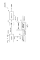
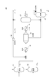
- the compound production system 100 is a system for producing a compound such as a fuel or a chemical material.
- the synthetic product is methanol, methane, dimethyl ether (DME) and the like.
- the composite production system 100 comprises a by-product hydrogen discharge plant 10 that discharges by-product hydrogen and a carbon dioxide-containing gas.
- a carbon dioxide emission plant 20 that emits carbon dioxide
- a synthesis plant 30 that produces a composite by synthesizing by-product hydrogen and carbon dioxide contained in a carbon dioxide-containing gas
- a by-product hydrogen supplied to the synthesis plant 30 is provided.
- the compound production system 100 produces a compound by using the carbon dioxide-containing gas emitted from the carbon dioxide emission plant 20 and the by-product hydrogen emitted from the by-product hydrogen emission plant 10. To do. In this case, since the acquisition cost of hydrogen is low, the production cost of the composite can be lowered.
- the flow rate adjusting device 40 is configured to guide carbon dioxide whose flow rate is adjusted with respect to the flow rate of by-product hydrogen supplied to the synthesis plant 30 to the synthesis plant 30. In this case, since the amount of carbon dioxide supplied is adjusted according to the amount of by-product hydrogen supplied, it is possible to increase the hydrogen utilization rate.
- the flow control device 40 recovers carbon dioxide from the carbon dioxide-containing gas emitted from the carbon dioxide emission plant 20. It includes a carbon dioxide capture device 42 and a recovery amount adjusting unit 41 configured to control the carbon dioxide recovery amount of the carbon dioxide recovery device 42.
- the flow rate adjusting device 40 is, for example, a sensor (not shown) for measuring the hydrogen flow rate of the supply pipe to the synthesis plant 30 and a by-product hydrogen storage device in order to adjust the flow rate of carbon dioxide with respect to the flow rate of by-product hydrogen.
- a sensor (not shown) for measuring the remaining amount of 50 may be provided.
- the carbon dioxide recovery device 42 may be configured to separate and recover carbon dioxide by, for example, a PSA (Pressure Swing Adsorption) method, or may be configured to separate and recover carbon dioxide by an amine absorption method.
- a PSA Pressure Swing Adsorption
- the amount of carbon dioxide recovered or the recovery rate is adjusted by repeating pressurization and depressurization.
- the recovery amount or recovery rate of carbon dioxide is adjusted by adjusting the flow rate of the absorption liquid.
- the recovery amount adjusting unit 41 may be configured to adjust the recovery rate of the carbon dioxide recovery device 42, and is not the recovery rate but the amount of carbon dioxide-containing gas led to the carbon dioxide recovery device 42 and the carbon dioxide recovery device.
- the configuration may be such that the amount of carbon dioxide-containing gas released to the outside without being guided to 42 is adjusted. Therefore, the exhaust gas of the carbon dioxide recovery device 42 may contain a carbon dioxide-containing gas that is released to the outside without being guided to the carbon dioxide recovery device 42, or the carbon dioxide-containing gas guided to the carbon dioxide recovery device 42. Of these, off-gas may be used after carbon dioxide is recovered.
- the composite production system 100 is a by-product hydrogen for accumulating the by-product hydrogen discharged from the by-product hydrogen discharge plant 10.
- a storage device 50 may be provided so that the by-product hydrogen storage device 50 can supply by-product hydrogen to the synthesis plant 30.
- the by-product hydrogen storage device 50 is a device for storing hydrogen, for example, a hydrogen storage alloy, a storage tank, or the like.
- the composite production system 100 provides a first supply line for supplying the by-product hydrogen discharged from the by-product hydrogen discharge plant 10 to the synthesis plant 30.
- the by-product hydrogen storage device 50 may be provided in the first supply branch line branched from the first supply line.
- the supply path from the by-product hydrogen storage device 50 to the synthesis plant 30 is another supply line provided in parallel with the first supply line.
- the supply route from the by-product hydrogen storage device 50 to the synthesis plant 30 may be the first supply line. That is, the by-product hydrogen storage device 50 may have a configuration in which the by-product hydrogen is supplied to the first supply line or the by-product hydrogen is supplied from the first supply line.
- the by-product hydrogen storage device 50 is provided in the first supply branch line branched from the first supply line, the by-product hydrogen is not passed through the by-product hydrogen storage device 50. It is also possible to supply to the synthesis plant 30 from one supply line. In this case, even when the synthesis plant 30 is in operation, the connection between the by-product hydrogen storage device 50 and the first supply line is cut (the first supply branch line is cut off) to maintain the by-product hydrogen storage device 50. It is also possible to do. As a result, the operating rate of the synthesis plant 30 can be improved.
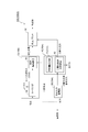
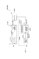
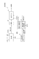
- the flow rate adjusting device 40 shown in FIGS. 1 to 6 and 9 is configured to control the flow rate of carbon dioxide according to the remaining amount of the by-product hydrogen storage device 50. May be good.
- the flow rate of carbon dioxide is reduced.
- the threshold value indicating the insufficient remaining amount (for example, 10% of the rating).
- Control to reduce the amount of carbon dioxide below normal control to increase the flow rate of carbon dioxide more than usual when the remaining amount of the by-product hydrogen storage device 50 exceeds the threshold value (for example, 90% of the rating) indicating that the capacity is over. Can be done. Therefore, it is possible to reduce the possibility that the remaining amount of the by-product hydrogen storage device 50 becomes excessively small or excessive.
- the composite production system 100 comprises a carbon dioxide storage device 60 for storing carbon dioxide, from the carbon dioxide storage device 60 to the synthesis plant 30. It is configured to be able to supply carbon dioxide.
- the carbon dioxide storage device 60 is a device for storing carbon dioxide, for example, a storage tank.
- carbon dioxide can be stably supplied to the synthesis plant 30.
- the carbon dioxide storage device 60 can be used. Therefore, carbon dioxide close to the amount of carbon dioxide corresponding to the amount of by-product hydrogen can be supplied to the synthesis plant 30. As a result, the operating rate of the synthesis plant 30 can be improved.
- the composite production system 100 supplies carbon dioxide contained in the carbon dioxide-containing gas emitted from the carbon dioxide emission plant 20 to the synthesis plant 30.
- a second supply line is provided, and the carbon dioxide storage device 60 may be provided in the second supply branch line branched from the second supply line.
- the supply path from the carbon dioxide storage device 60 to the synthesis plant 30 is another supply line provided in parallel with the second supply line.
- the supply route from the carbon dioxide storage device 60 to the synthesis plant 30 may be the second supply line. That is, the carbon dioxide storage device 60 may have a configuration in which carbon dioxide is supplied to the second supply line or carbon dioxide is supplied from the second supply line.
- the carbon dioxide storage device 60 is provided in the second supply branch line branched from the second supply line, carbon dioxide is synthesized from the second supply line without going through the carbon dioxide storage device 60. It can also be supplied to the plant 30. In this case, even when the synthesis plant 30 is in operation, the connection between the carbon dioxide storage device 60 and the second supply line is cut (the second supply branch line is cut off) to maintain the carbon dioxide storage device 60. It is also possible. As a result, the operating rate of the synthesis plant can be improved.
- the flow control device 40 shown in FIGS. 1 and 2 recovers carbon dioxide from the carbon dioxide-containing gas discharged from the carbon dioxide emission plant 20 and supplies carbon dioxide to the carbon dioxide storage device 60 and the synthesis plant 30. It includes a carbon capture device 42 and a recovery amount adjusting unit 41 configured to control the carbon dioxide recovery amount of the carbon dioxide recovery device 42.
- the flow rate regulator 40 may be configured to control the amount of carbon dioxide recovered according to the remaining amount of the carbon dioxide storage device 60.
- the flow rate adjusting device 40 includes a sensor (not shown) for measuring the remaining amount of the carbon dioxide storage device 60, a supply amount of carbon dioxide to the carbon dioxide storage device 60, and a supply amount of carbon dioxide from the carbon dioxide storage device 60. A sensor (not shown) or the like for measuring carbon dioxide may be provided.
- the amount of carbon dioxide recovered is usually taken.
- Control to increase the amount of carbon dioxide control to reduce the amount of carbon dioxide recovered when the remaining amount of the carbon dioxide storage device 60 exceeds the threshold (for example, 90% of the rating) indicating that the capacity is over. It becomes possible to do. Therefore, it is possible to reduce the possibility that the remaining amount of the carbon dioxide storage device 60 becomes excessively low or excessive.
- the by-product hydrogen discharge plant 10 is a plant that produces caustic soda, such as the by-product hydrogen discharge plant 10 (10A) shown in FIGS. 3 to 6 and 9, for example. It may be configured to produce by-product hydrogen in salt electrolysis for production.
- Carbon dioxide and hydrogen supplied to the synthesis plant 30 need to be refined with high purity.
- impurities are contained in the by-product hydrogen, for example, the reaction rate or the reaction rate at the time of producing the synthetic product may decrease, which may hinder the production of the synthetic product.
- the by-product hydrogen discharge plant 10 (10A) discharges high-purity by-product hydrogen, the cost required for the hydrogen purification process can be reduced.
- At least a part of the generated power of the carbon dioxide emission plant 20 is supplied to the by-product hydrogen emission plant 10 or the synthesis plant 30.
- the carbon dioxide emission plant 20 is a cement factory 20 (20B), and at least a part of the generated power of the power generation device 90 using the exhaust heat of the cement factory 20 (20B) is by-product hydrogen. It may be supplied to the discharge plant 10 or the synthesis plant 30.
- the carbon dioxide emission plant 20 is a coal-fired power plant 20 (20A), and at least a part of the generated power is supplied to the by-product hydrogen emission plant 10 or the synthesis plant 30. Will be done.
- the efficiency of energy utilization can be improved by supplying at least a part of the generated power of the carbon dioxide emission plant 20 to the by-product hydrogen emission plant 10 or the synthesis plant 30.
- the composite production system 100 is configured to supply the waste heat of the carbon dioxide emission plant 20 to the synthesis plant 30, as in the composite production system 100 (100I) shown in FIG. 9, for example. It may have been done.
- the synthesis plant 30 can utilize the exhaust heat of the carbon dioxide emission plant 20 to improve the efficiency of energy utilization.
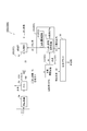
- FIG. 10 is a diagram schematically showing the configuration of the synthesis plant 30 according to the embodiment.
- the synthesis plant 30 includes a hydrogen purification unit 31 for purifying hydrogen and a carbon dioxide purification unit 32 for purifying carbon dioxide. When high-purity by-product hydrogen and carbon dioxide are supplied, these configurations are unnecessary.
- the synthesis plant 30 has a heating unit 33 for heating a gas in which hydrogen and carbon dioxide are mixed, a catalyst 34 for chemically reacting hydrogen and carbon dioxide to produce a compound (methanol), and distillation.
- a distillation unit 36 configured to perform the above is provided.
- the synthesis plant 30 includes a cooling unit 35 for circulating a gas that did not contribute to the production of the composite, a flash tank 37, and a compressor 38.
- Hydrogen and carbon dioxide supplied from the hydrogen refining unit 31 and the carbon dioxide refining unit 32 are heated by the heating unit 33 in a mixed state and guided to the catalyst 34.
- the catalyst 34 the gas in which hydrogen and carbon dioxide are mixed chemically reacts. This produces a composite.
- the produced synthetic product is separated into water and the final product (high-purity methanol) by distillation in the distillation unit 36. In such a synthesis plant 30, heating is required in the heating unit 33 and the distillation unit 36.
- the exhaust heat of the carbon dioxide emission plant 20 in the compound production system 100 (100I) shown in FIG. 9 is heating for reacting carbon dioxide and by-product hydrogen in the synthesis plant 30 ( That is, it may be used for heating by the heating unit 33 before leading to the catalyst 34).
- the synthesis plant 30 uses the exhaust heat of the carbon dioxide emission plant 20 for heating for reacting carbon dioxide and by-product hydrogen in the synthesis plant 30, it is possible to improve the efficiency of energy utilization. it can.
- the exhaust heat of the carbon dioxide emission plant 20 in the composition production system 100 (100I) shown in FIG. 9 is heating (ie,) for purifying the final product from the composition of the synthesis plant 30. It is used in the heating required for distillation of the distillation unit 36).
- the synthesis plant 30 uses the waste heat of the carbon dioxide emission plant 20 for heating to purify the final product from the synthesis, so that the efficiency of energy utilization can be improved.
- the by-product hydrogen discharge plant 10 (10A) is configured to use pure water supplied from the carbon dioxide discharge plant 20 to produce caustic soda. May be.
- the by-product hydrogen discharge plant 10 and the carbon dioxide discharge plant 20 share pure water, so that the equipment for supplying pure water can be simplified.
- the coal-fired power plant 20 (20A) steam is generated by a boiler and a generator is driven by a steam turbine. Pure water is used to supply water to this boiler.
- the coal-fired power plant 20 (20A) is equipped with a pure water supply line (not shown) for replenishing the water supply used in the boiler.
- the cement factory 20 (20B) steam is generated by the exhaust heat generated in the cement manufacturing process, and the power generation device 90 is driven by the steam turbine to use the electric power in the factory. Therefore, the cement factory 20 (20B) is provided with a pure water supply line for supplying pure water for generating steam to the steam turbine.
- the carbon dioxide emission plant 20 for example, the coal-fired power plant 20 (20A) and the cement plant 20 (20B)
- the compound production system 100 may include a pure water supply device 91, for example, as in the compound production system 100 (100F) shown in FIG.
- the pure water supply device 91 is configured to remove impurities in raw water to produce pure water, and is configured to supply pure water to the by-product hydrogen discharge plant 10 and the carbon dioxide discharge plant 20.
- the carbon dioxide emission plant 20 (20C) is obtained by modifying naphtha, for example, as in the compound production system 100 (100J, 100K, 100L, 100M) shown in FIGS. 11-14. It may be configured to emit carbon dioxide-containing gas.
- the carbon dioxide emission plant 20 (20C) has a reformer 94 for reforming naphtha, a PSA device 95 for separating hydrogen from the reformed naphtha by the PSA method, and a PSA off gas of the PSA device 95. Is provided with a three-way valve 96 for dividing the flow into the heating furnace 97 and the flow rate adjusting device 40 (40B), and a heating furnace 97 for performing oil refining.
- the hydrogen separated by the PSA device 95 is not used in the synthetic product, but is provided as a product to a hydrogen station or the like.
- the by-product hydrogen discharge plant 10 (10C) is a hydrogen generator, and is a hydrogen-containing gas (carbon dioxide lean gas) obtained from the carbon dioxide-containing gas (carbon dioxide rich gas) discharged by the carbon dioxide discharge plant 20 (20C). On the other hand, it is configured to discharge by-product hydrogen obtained by performing hydrogen purification.
- the numerical value not represented by the symbol exemplifies the ratio of the gas amount of each flow path to the gas amount of PSA off gas discharged from the PSA device 95 as 100%.
- the composition of PSA off-gas is, for example, 50% by volume of carbon dioxide, 40% by volume of hydrogen, 10% by volume of methane and the like.
- the composite production system 100 is a carbon dioxide capture device 42 that recovers carbon dioxide from a carbon dioxide-containing gas emitted from the carbon dioxide emission plant 20 (20C).
- the by-product hydrogen discharge plant 10 (10C) may be configured such that the carbon dioxide recovery device 42 performs hydrogen purification on the hydrogen-containing gas after the carbon dioxide is recovered.
- the by-product hydrogen discharge plant 10 (10C) performs hydrogen purification on the hydrogen-containing gas (carbon dioxide lean gas) after recovering carbon dioxide, so that by-product hydrogen can be efficiently obtained. Can be done. Further, since the volume processed by the by-product hydrogen discharge plant 10 (10C) is smaller than that when the carbon dioxide-containing gas (carbon dioxide-rich gas) is processed, the by-product hydrogen discharge plant 10 (10C) is downsized (small). Capacity can be increased).
- the composite production system 100 is a carbon dioxide capture device 42 that recovers carbon dioxide from a carbon dioxide-containing gas emitted from the carbon dioxide emission plant 20 (20C).
- the by-product hydrogen discharge plant 10 (10C) includes a hydrogen purification device provided on the flow path through which the carbon dioxide-containing gas flows from the carbon dioxide discharge plant 20 (20C) to the carbon dioxide recovery device 42. Good.
- the carbon dioxide recovery device 42 recovers carbon dioxide from the carbon dioxide-containing gas (hydrogen lean gas) after the by-product hydrogen discharge plant 10 (10C) purifies hydrogen, so that the carbon dioxide is efficient. It can be recovered well. Further, since the volume processed by the carbon dioxide recovery device 42 is smaller than that in the case of recovering carbon dioxide from the carbon dioxide-containing gas (hydrogen-rich gas) before hydrogen purification, the carbon dioxide recovery device 42 is downsized (). Can be reduced in capacity).
- the flow rate regulator 40 (40A) is supplied to the synthesis plant 30 by controlling the recovery rate of the carbon dioxide capture device 42. It is configured to guide carbon dioxide whose flow rate is adjusted with respect to the flow rate of raw hydrogen to the synthesis plant 30.
- the carbon dioxide recovery rate is controlled based on the amount of carbon dioxide required when producing a compound with the hydrogen recovery rate set to 100%, the carbon dioxide emission plant 20 (20C) Even when the composition of the carbon dioxide-containing gas emitted by the gas changes, the hydrogen recovery rate can be fixed at 100%.
- the composite production system 100 is connected to a carbon dioxide capture device 42 that recovers carbon dioxide from a carbon dioxide-containing gas and a carbon dioxide capture device 42. It is provided with at least one valve 43 for adjusting the flow ratio between the mainstream line to be used and the bypass line that bypasses the carbon dioxide capture device 42. At least one valve 43 is one three-way valve in the example shown in FIGS. 13 and 14. The valve 43 may be not a three-way valve but two valves for adjusting the flow rates of the mainstream line and the bypass line.
- the compound production system 100 (100L) shown in FIG. 13 includes a carbon dioxide recovery device 42 that recovers carbon dioxide from one of the carbon dioxide-containing gases separated by the valve 43, and is a by-product hydrogen discharge plant.
- No. 10 (10C) hydrogen purification is performed on the carbon dioxide-containing gas after the carbon dioxide recovery device 42 has recovered the carbon dioxide and the other carbon dioxide-containing gas separated by the valve 43.
- the by-product hydrogen discharge plant 10 performs hydrogen purification on the carbon dioxide-containing gas after the carbon dioxide recovery device 42 has recovered the carbon dioxide and the other carbon dioxide-containing gas separated by the valve 43, By-product hydrogen can be obtained efficiently.
- the by-product hydrogen discharge plant 10 (10C) purifies the carbon dioxide-containing gas discharged from the carbon dioxide emission plant 20 (20C) with a valve.
- the carbon dioxide-containing gas after hydrogen purification by the by-product hydrogen discharge plant 10 (10C) is divided into two, and the carbon dioxide recovery device 42 divides one of the carbon dioxide-containing gases separated by the valve 43.
- the carbon dioxide recovery device 42 recovers carbon dioxide from one of the carbon dioxide-containing gases separated by the valve 43 after the by-product hydrogen discharge plant 10 has refined hydrogen, so that carbon dioxide is efficiently acquired. can do.
- the volume of the carbon dioxide-containing gas processed by the carbon dioxide recovery device can be reduced by adjusting the flow rate ratio between the mainstream line and the bypass line, so that the carbon dioxide recovery device can be miniaturized (small). Capacity can be increased).
- the flow rate regulator 40 (40B) has a flow rate relative to the flow rate of by-product hydrogen supplied to the synthesis plant 30 by controlling the flow rate ratio. It may be configured to lead the adjusted carbon dioxide to the synthesis plant 30.
- the carbon dioxide recovery rate and the hydrogen recovery rate can be fixed by controlling the flow rate ratio.
- the synthesis plant 30 is configured to produce at least one of methanol, methane, and dimethyl ether as the compound. According to such a configuration, it is possible to produce a compound having excellent storage stability as compared with hydrogen gas.
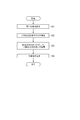
- FIG. 15 is a flowchart showing a compound production method according to an embodiment of the present invention.
- the compound production system 100 discharges by-product hydrogen (step S1).
- the composite production system 100 emits a carbon dioxide-containing gas (step S2). It should be noted that these steps may be performed at the same time, or there may be a time difference.
- the composite production system 100 extracts a part from the carbon dioxide emitted in the carbon dioxide emission step, and synthesizes carbon dioxide whose flow rate is adjusted with respect to the flow rate of by-product hydrogen used in the next step S4. Guide (step S3).
- the composite product production system 100 produces a composite product by synthesizing by-product hydrogen and carbon dioxide contained in the carbon dioxide-containing gas (step S4).
- a compound is produced by using the carbon dioxide-containing gas emitted in the carbon dioxide emission step (step S1) and the by-product hydrogen emitted in the by-product hydrogen emission step (step S2). Produce.
- the acquisition cost of hydrogen is low, the production cost of the composite can be lowered.
- the flow rate adjusting step (step S3) carbon dioxide whose flow rate is adjusted with respect to the flow rate of by-product hydrogen used in the compound production step (step S4) is guided to synthesis.
- the amount of carbon dioxide supplied is adjusted according to the amount of by-product hydrogen supplied, it is possible to increase the hydrogen utilization rate.
- the present invention is not limited to the above-described embodiment, and includes a modified form of the above-described embodiment and a combination of these embodiments as appropriate.
Landscapes
- Chemical & Material Sciences (AREA)
- Organic Chemistry (AREA)
- Chemical Kinetics & Catalysis (AREA)
- Engineering & Computer Science (AREA)
- Electrochemistry (AREA)
- Metallurgy (AREA)
- Materials Engineering (AREA)
- Inorganic Chemistry (AREA)
- General Chemical & Material Sciences (AREA)
- Oil, Petroleum & Natural Gas (AREA)
- Organic Low-Molecular-Weight Compounds And Preparation Thereof (AREA)
- Carbon And Carbon Compounds (AREA)
- Hydrogen, Water And Hydrids (AREA)
Priority Applications (2)
| Application Number | Priority Date | Filing Date | Title |
|---|---|---|---|
| CN202080033023.6A CN113784785A (zh) | 2019-05-24 | 2020-05-18 | 合成物生产系统及合成物生产方法 |
| DE112020001970.5T DE112020001970T5 (de) | 2019-05-24 | 2020-05-18 | Synthetik-Produkt-Herstellungssystem und Synthetik-Produktherstellungsverfahren |
Applications Claiming Priority (2)
| Application Number | Priority Date | Filing Date | Title |
|---|---|---|---|
| JP2019-097275 | 2019-05-24 | ||
| JP2019097275A JP7432997B2 (ja) | 2019-05-24 | 2019-05-24 | 合成物生産システム及び合成物生産方法 |
Publications (1)
| Publication Number | Publication Date |
|---|---|
| WO2020241343A1 true WO2020241343A1 (ja) | 2020-12-03 |
Family
ID=73454321
Family Applications (1)
| Application Number | Title | Priority Date | Filing Date |
|---|---|---|---|
| PCT/JP2020/019603 Ceased WO2020241343A1 (ja) | 2019-05-24 | 2020-05-18 | 合成物生産システム及び合成物生産方法 |
Country Status (4)
| Country | Link |
|---|---|
| JP (1) | JP7432997B2 (https=) |
| CN (1) | CN113784785A (https=) |
| DE (1) | DE112020001970T5 (https=) |
| WO (1) | WO2020241343A1 (https=) |
Cited By (1)
| Publication number | Priority date | Publication date | Assignee | Title |
|---|---|---|---|---|
| WO2021166983A1 (ja) * | 2020-02-20 | 2021-08-26 | 三菱パワー株式会社 | 合成物生産システム |
Families Citing this family (2)
| Publication number | Priority date | Publication date | Assignee | Title |
|---|---|---|---|---|
| JP7817011B2 (ja) | 2022-02-25 | 2026-02-18 | 三菱重工業株式会社 | プラント |
| WO2023195266A1 (ja) * | 2022-04-08 | 2023-10-12 | 株式会社Ihi | 反応システム |
Citations (2)
| Publication number | Priority date | Publication date | Assignee | Title |
|---|---|---|---|---|
| JPH10263400A (ja) * | 1997-03-24 | 1998-10-06 | Ishii Iron Works Co Ltd | 炭化水素改質ガス用アモルファス合金触媒とその用法 |
| JP2015109767A (ja) * | 2013-12-05 | 2015-06-11 | 株式会社Ihi | 発電システム |
Family Cites Families (24)
| Publication number | Priority date | Publication date | Assignee | Title |
|---|---|---|---|---|
| JP3479950B1 (ja) | 2003-03-04 | 2003-12-15 | スガ試験機株式会社 | 環境浄化循環型水電解装置 |
| JP2006137620A (ja) | 2004-11-10 | 2006-06-01 | Toshiba Corp | 排ガス中の二酸化炭素の回収システムおよび回収方法 |
| JP5082254B2 (ja) | 2005-02-18 | 2012-11-28 | 三菱化学株式会社 | 芳香族化合物の製造方法及び水素化芳香族化合物の製造方法 |
| EP2228358A1 (en) | 2009-03-13 | 2010-09-15 | Methanol Casale S.A. | Recovery of CO2 in a process for synthesis of methanol |
| JP2012076065A (ja) | 2010-10-06 | 2012-04-19 | Ihi Corp | 二酸化炭素の回収方法及び回収装置 |
| JP2012184139A (ja) | 2011-03-07 | 2012-09-27 | Hitachi Ltd | 二酸化炭素分離装置 |
| CN102351624B (zh) | 2011-08-24 | 2013-12-11 | 西安交通大学 | 一种co2加氢制取低碳烯烃的系统 |
| CN103773524A (zh) | 2012-10-19 | 2014-05-07 | 中冶焦耐工程技术有限公司 | 液化天然气的制造方法 |
| DE102013002583A1 (de) * | 2013-02-14 | 2014-08-14 | Etogas Gmbh | Umwandlungsverfahren und Reaktorsystem dafür |
| KR102225779B1 (ko) | 2013-07-09 | 2021-03-11 | 미츠비시 히타치 파워 시스템스 유럽 게엠베하 | 융통성있게 작동가능한 발전 플랜트 및 그의 작동 방법 |
| WO2015033583A1 (ja) * | 2013-09-09 | 2015-03-12 | 千代田化工建設株式会社 | 水素及び合成天然ガスの製造装置及び製造方法 |
| JP6299347B2 (ja) * | 2014-04-01 | 2018-03-28 | 株式会社Ihi | 二酸化炭素固定システム |
| DE102014112580B4 (de) | 2014-09-01 | 2019-01-24 | Mitsubishi Hitachi Power Systems Europe Gmbh | Industrielle Produktionsanlage mit minimalem Treibhausgasausstoß, insbesondere Kohlendioxidausstoß, und Verfahren zum Betrieb desselben |
| CN104371780B (zh) | 2014-11-03 | 2016-06-08 | 中国华能集团清洁能源技术研究院有限公司 | 风、光弃电和工业有机废水用于煤制天然气的系统及方法 |
| CN104725179A (zh) * | 2015-01-08 | 2015-06-24 | 江苏省宏观经济研究院 | 一种基于非并网风电的二氧化碳循环利用的方法 |
| CN104974780B (zh) | 2015-06-09 | 2017-03-08 | 武汉凯迪工程技术研究总院有限公司 | 氯碱法与费托合成综合利用调节工艺及其设备 |
| FR3038908A1 (fr) | 2015-07-16 | 2017-01-20 | Gdf Suez | Dispositif et procede de production de gaz de synthese |
| CN105296033A (zh) | 2015-11-03 | 2016-02-03 | 中海石油气电集团有限责任公司 | 一种高效利用液化工序弛放气的焦炉煤气制lng的方法 |
| CA3005639C (en) * | 2015-11-16 | 2021-05-18 | Fuelcell Energy, Inc. | Energy storage using an rep with an engine |
| FR3050206B1 (fr) * | 2016-04-15 | 2018-05-11 | Engie | Dispositif et procede d'hydrogenation pour produire du methanol et dispositif et procede de cogeneration de methanol et de methane de synthese |
| CN105779047A (zh) | 2016-04-22 | 2016-07-20 | 北京中科瑞奥能源科技股份有限公司 | 利用烟道气制液化天然气的工艺与系统 |
| CN106831326A (zh) | 2016-12-22 | 2017-06-13 | 赛鼎工程有限公司 | 一种焦炉煤气合成甲醇并联产液化天然气的综合利用工艺 |
| JP2018135283A (ja) | 2017-02-21 | 2018-08-30 | 株式会社日立製作所 | メタン製造方法及びメタン製造装置 |
| JP7028600B2 (ja) | 2017-10-10 | 2022-03-02 | 株式会社日立製作所 | メタン製造システム及びメタン製造方法 |
-
2019
- 2019-05-24 JP JP2019097275A patent/JP7432997B2/ja active Active
-
2020
- 2020-05-18 DE DE112020001970.5T patent/DE112020001970T5/de active Pending
- 2020-05-18 WO PCT/JP2020/019603 patent/WO2020241343A1/ja not_active Ceased
- 2020-05-18 CN CN202080033023.6A patent/CN113784785A/zh active Pending
Patent Citations (2)
| Publication number | Priority date | Publication date | Assignee | Title |
|---|---|---|---|---|
| JPH10263400A (ja) * | 1997-03-24 | 1998-10-06 | Ishii Iron Works Co Ltd | 炭化水素改質ガス用アモルファス合金触媒とその用法 |
| JP2015109767A (ja) * | 2013-12-05 | 2015-06-11 | 株式会社Ihi | 発電システム |
Non-Patent Citations (1)
| Title |
|---|
| FUKUOKA, MASAO: "Utilization of Hydrogen from Chlor-Alkali Industry in Japan", JOURNAL OF THE HYDROGEN ENERGY SYSTEMS SOCIETY OF JAPAN, vol. 28, no. 1, 2003, pages 16 - 22 * |
Cited By (1)
| Publication number | Priority date | Publication date | Assignee | Title |
|---|---|---|---|---|
| WO2021166983A1 (ja) * | 2020-02-20 | 2021-08-26 | 三菱パワー株式会社 | 合成物生産システム |
Also Published As
| Publication number | Publication date |
|---|---|
| CN113784785A (zh) | 2021-12-10 |
| JP7432997B2 (ja) | 2024-02-19 |
| JP2020189817A (ja) | 2020-11-26 |
| DE112020001970T5 (de) | 2021-12-30 |
Similar Documents
| Publication | Publication Date | Title |
|---|---|---|
| KR102243776B1 (ko) | 발전 플랜트 연도 가스의 co₂ 메탄화를 포함하는 메탄화 방법 및 발전 플랜트 | |
| EP2196448B1 (en) | Method of coproducing methanol and ammonia | |
| JP7353163B2 (ja) | アンモニア誘導体製造プラント及びアンモニア誘導体の製造方法 | |
| JP6603607B2 (ja) | メタノール合成システム | |
| JP2024503997A (ja) | メタノールおよび炭化水素生成物を製造するための二酸化炭素と水の合成ガスへの変換 | |
| HU222969B1 (hu) | Eljárás villamos energia, gőz és szén-dioxid termelésére szénhidrogén nyersanyagból | |
| JP6263029B2 (ja) | メタン製造方法並びにメタン製造装置及びこれを用いたガス化システム | |
| JP5636059B2 (ja) | ナトリウムイオン分離膜を用いて水素を産生するための方法およびシステム | |
| EP3403291A1 (en) | System for capturing co2 from a fuel cell | |
| WO2020241343A1 (ja) | 合成物生産システム及び合成物生産方法 | |
| JP7686552B2 (ja) | 二酸化炭素変換装置及び二酸化炭素変換方法 | |
| DK181576B1 (en) | Conversion of carbon dioxide and water to synthesis gas | |
| JP2013119556A (ja) | 燃料製造方法及び燃料製造装置 | |
| US12391636B2 (en) | Method and system to produce hydrocarbon feedstocks | |
| JP4030846B2 (ja) | メタノールの製造方法および装置 | |
| WO2019073722A1 (ja) | メタン製造システム及びメタン製造方法 | |
| AU2022290085A1 (en) | Method for recycling unused gas in membrane reactor | |
| KR20230122589A (ko) | 탄소 산화물을 올레핀으로 전환하기 위한 방법 및 시스템 | |
| CA3022543A1 (en) | Carbon dioxide capturing steam methane reformer | |
| JP2012188360A (ja) | 排熱・再生可能エネルギ利用反応物製造方法および製造システム | |
| JP4473223B2 (ja) | 改良されたシフト転化の構成と方法 | |
| CA3247308A1 (en) | METHOD AND SYSTEM FOR CAPTURING AND USING CARBON DIOXIDE | |
| CN113423869B (zh) | 用于氨合成气生产的环境空气分离和soec前端 | |
| JP2016184550A (ja) | ガス製造装置 | |
| JP6863124B2 (ja) | 燃料電池発電システム |
Legal Events
| Date | Code | Title | Description |
|---|---|---|---|
| 121 | Ep: the epo has been informed by wipo that ep was designated in this application |
Ref document number: 20813701 Country of ref document: EP Kind code of ref document: A1 |
|
| 122 | Ep: pct application non-entry in european phase |
Ref document number: 20813701 Country of ref document: EP Kind code of ref document: A1 |