WO2020230312A1 - 運転支援方法及び運転支援システム - Google Patents
運転支援方法及び運転支援システム Download PDFInfo
- Publication number
- WO2020230312A1 WO2020230312A1 PCT/JP2019/019406 JP2019019406W WO2020230312A1 WO 2020230312 A1 WO2020230312 A1 WO 2020230312A1 JP 2019019406 W JP2019019406 W JP 2019019406W WO 2020230312 A1 WO2020230312 A1 WO 2020230312A1
- Authority
- WO
- WIPO (PCT)
- Prior art keywords
- driver
- lane change
- vehicle
- controller
- hands
- Prior art date
- Legal status (The legal status is an assumption and is not a legal conclusion. Google has not performed a legal analysis and makes no representation as to the accuracy of the status listed.)
- Ceased
Links
Images


Classifications
-
- H—ELECTRICITY
- H04—ELECTRIC COMMUNICATION TECHNIQUE
- H04W—WIRELESS COMMUNICATION NETWORKS
- H04W4/00—Services specially adapted for wireless communication networks; Facilities therefor
- H04W4/30—Services specially adapted for particular environments, situations or purposes
- H04W4/40—Services specially adapted for particular environments, situations or purposes for vehicles, e.g. vehicle-to-pedestrians [V2P]
-
- B—PERFORMING OPERATIONS; TRANSPORTING
- B60—VEHICLES IN GENERAL
- B60W—CONJOINT CONTROL OF VEHICLE SUB-UNITS OF DIFFERENT TYPE OR DIFFERENT FUNCTION; CONTROL SYSTEMS SPECIALLY ADAPTED FOR HYBRID VEHICLES; ROAD VEHICLE DRIVE CONTROL SYSTEMS FOR PURPOSES NOT RELATED TO THE CONTROL OF A PARTICULAR SUB-UNIT
- B60W40/00—Estimation or calculation of non-directly measurable driving parameters for road vehicle drive control systems not related to the control of a particular sub unit, e.g. by using mathematical models
- B60W40/08—Estimation or calculation of non-directly measurable driving parameters for road vehicle drive control systems not related to the control of a particular sub unit, e.g. by using mathematical models related to drivers or passengers
-
- B—PERFORMING OPERATIONS; TRANSPORTING
- B60—VEHICLES IN GENERAL
- B60W—CONJOINT CONTROL OF VEHICLE SUB-UNITS OF DIFFERENT TYPE OR DIFFERENT FUNCTION; CONTROL SYSTEMS SPECIALLY ADAPTED FOR HYBRID VEHICLES; ROAD VEHICLE DRIVE CONTROL SYSTEMS FOR PURPOSES NOT RELATED TO THE CONTROL OF A PARTICULAR SUB-UNIT
- B60W50/00—Details of control systems for road vehicle drive control not related to the control of a particular sub-unit, e.g. process diagnostic or vehicle driver interfaces
- B60W50/08—Interaction between the driver and the control system
- B60W50/14—Means for informing the driver, warning the driver or prompting a driver intervention
- B60W50/16—Tactile feedback to the driver, e.g. vibration or force feedback to the driver on the steering wheel or the accelerator pedal
-
- B—PERFORMING OPERATIONS; TRANSPORTING
- B60—VEHICLES IN GENERAL
- B60W—CONJOINT CONTROL OF VEHICLE SUB-UNITS OF DIFFERENT TYPE OR DIFFERENT FUNCTION; CONTROL SYSTEMS SPECIALLY ADAPTED FOR HYBRID VEHICLES; ROAD VEHICLE DRIVE CONTROL SYSTEMS FOR PURPOSES NOT RELATED TO THE CONTROL OF A PARTICULAR SUB-UNIT
- B60W60/00—Drive control systems specially adapted for autonomous road vehicles
- B60W60/001—Planning or execution of driving tasks
-
- G—PHYSICS
- G08—SIGNALLING
- G08B—SIGNALLING SYSTEMS, e.g. PERSONAL CALLING SYSTEMS; ORDER TELEGRAPHS; ALARM SYSTEMS
- G08B21/00—Alarms responsive to a single specified undesired or abnormal condition and not otherwise provided for
- G08B21/02—Alarms for ensuring the safety of persons
- G08B21/06—Alarms for ensuring the safety of persons indicating a condition of sleep, e.g. anti-dozing alarms
-
- G—PHYSICS
- G08—SIGNALLING
- G08G—TRAFFIC CONTROL SYSTEMS
- G08G1/00—Traffic control systems for road vehicles
- G08G1/16—Anti-collision systems
-
- B—PERFORMING OPERATIONS; TRANSPORTING
- B60—VEHICLES IN GENERAL
- B60W—CONJOINT CONTROL OF VEHICLE SUB-UNITS OF DIFFERENT TYPE OR DIFFERENT FUNCTION; CONTROL SYSTEMS SPECIALLY ADAPTED FOR HYBRID VEHICLES; ROAD VEHICLE DRIVE CONTROL SYSTEMS FOR PURPOSES NOT RELATED TO THE CONTROL OF A PARTICULAR SUB-UNIT
- B60W2520/00—Input parameters relating to overall vehicle dynamics
- B60W2520/04—Vehicle stop
-
- B—PERFORMING OPERATIONS; TRANSPORTING
- B60—VEHICLES IN GENERAL
- B60W—CONJOINT CONTROL OF VEHICLE SUB-UNITS OF DIFFERENT TYPE OR DIFFERENT FUNCTION; CONTROL SYSTEMS SPECIALLY ADAPTED FOR HYBRID VEHICLES; ROAD VEHICLE DRIVE CONTROL SYSTEMS FOR PURPOSES NOT RELATED TO THE CONTROL OF A PARTICULAR SUB-UNIT
- B60W2540/00—Input parameters relating to occupants
- B60W2540/223—Posture, e.g. hand, foot, or seat position, turned or inclined
-
- B—PERFORMING OPERATIONS; TRANSPORTING
- B60—VEHICLES IN GENERAL
- B60W—CONJOINT CONTROL OF VEHICLE SUB-UNITS OF DIFFERENT TYPE OR DIFFERENT FUNCTION; CONTROL SYSTEMS SPECIALLY ADAPTED FOR HYBRID VEHICLES; ROAD VEHICLE DRIVE CONTROL SYSTEMS FOR PURPOSES NOT RELATED TO THE CONTROL OF A PARTICULAR SUB-UNIT
- B60W2552/00—Input parameters relating to infrastructure
- B60W2552/10—Number of lanes
-
- B—PERFORMING OPERATIONS; TRANSPORTING
- B60—VEHICLES IN GENERAL
- B60W—CONJOINT CONTROL OF VEHICLE SUB-UNITS OF DIFFERENT TYPE OR DIFFERENT FUNCTION; CONTROL SYSTEMS SPECIALLY ADAPTED FOR HYBRID VEHICLES; ROAD VEHICLE DRIVE CONTROL SYSTEMS FOR PURPOSES NOT RELATED TO THE CONTROL OF A PARTICULAR SUB-UNIT
- B60W2710/00—Output or target parameters relating to a particular sub-units
- B60W2710/18—Braking system
Definitions
- the present invention relates to a driving support method and a driving support system.
- JP2018-151765A discloses a visual recognition support device that issues a warning when the driver has not visually observed the part to be monitored for a predetermined time.
- the outside camera detects an object existing around the vehicle, the type of the detected object is specified, and the in-vehicle camera detects the visual state of the driver. Then, based on the type of the target and the visual condition of the driver, it is determined whether or not the visual inspection of the driver is appropriate, and if it is determined to be inappropriate, a warning is issued.
- an object of the present invention is to provide a driving support method and a driving support system capable of reducing unnecessary warnings by a simple method.
- the controller acquires the state information of the driver during automatic driving, and when it is determined that the driver is facing other than the front based on the state information of the driver, the driver A driving assistance method that gives a warning is provided.
- this driving support method a warning is prohibited when the driver is facing the lane change direction during automatic driving.
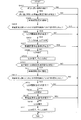
- FIG. 1 is a schematic configuration diagram of a driving support system according to the present embodiment.
- FIG. 2 is a flowchart showing vehicle speed control according to the present embodiment.
- FIG. 3 is a flowchart showing the lane center maintenance control of the present embodiment.
- FIG. 4 is a diagram showing lane change control when the driver starts a winker operation as a trigger.
- FIG. 5 is a flowchart showing lane change control when the driver starts a winker operation as a trigger.
- FIG. 6 is a diagram showing lane change control by the overtaking support function.
- FIG. 7 is a flowchart showing lane change control by the overtaking support function.
- FIG. 8 is a diagram showing lane change control by the route traveling support function.
- FIG. 1 is a schematic configuration diagram of a driving support system according to the present embodiment.
- FIG. 2 is a flowchart showing vehicle speed control according to the present embodiment.
- FIG. 3 is a flowchart showing the lane center maintenance control of the present embodiment
- FIG. 9 is a flowchart showing lane change control by the route traveling support function.
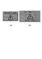
- FIG. 10 is a diagram showing an example of a warning screen for a forward gaze warning.
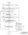
- FIG. 11 is a flowchart showing control of the notification operation of the forward gaze alarm.
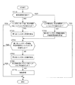
- FIG. 12 is a diagram showing an example of a warning screen of the first hands-on alarm.
- FIG. 13 is a diagram showing an example of a warning screen for the second hands-on alarm.
- FIG. 14 is a flowchart showing the control of the notification operation of the hands-on alarm that is started when the mode is switched to the hands-on mode.
- FIG. 15 is a flowchart showing control of the notification operation of the hands-on alarm that is started when the forward gaze alarm is notified in the hands-off mode.
- FIG. 1 is a schematic configuration diagram of the driving support system 100 according to the first embodiment.
- the driver assistance system 100 includes an external sensor 1, an internal sensor 2, a navigation system 3, an in-vehicle device 4, a presentation device 5, an input device 6, and an actuator 7. And a controller 8.
- the driving support system 100 is mounted on a vehicle (own vehicle) 10 having an automatic driving function.
- the external sensor 1 is a detection device that detects an external situation that is peripheral information of the own vehicle 10.
- the external sensor 1 detects, for example, other vehicles around the own vehicle 10, lane markers, road types (motorways, general roads, etc.) and the like.
- the external sensor 1 includes an external camera 11 and a radar 12.
- the vehicle outside camera 11 is an imaging device that images the external situation of the own vehicle 10, and acquires imaging information about the external situation of the own vehicle 10.
- the vehicle exterior camera 11 is, for example, an around view monitor camera provided on the front, rear, and left and right doors of the vehicle interior of the vehicle 10, a front camera provided on the windshield of the vehicle interior or outside, and behind the vehicle 10.
- the rear camera to be installed.
- the radar 12 detects an object outside the own vehicle 10 using radio waves.
- the radio wave is, for example, millimeter wave. More specifically, the radar 12 transmits radio waves around the own vehicle 10 and receives the radio waves reflected by the object to detect the object.
- the radar 12 can acquire, for example, the distance or direction to an object as object information.
- the external sensor 1 outputs the acquired peripheral information (imaging information, object information) of the own vehicle 10 to the controller 8.
- the internal sensor 2 is a detection device that detects the state of the driver.
- the internal sensor 2 includes a driver monitor camera 21, a touch sensor 22, and the like.
- the driver monitor camera 21 is a monitor unit that captures the state of the driver and performs image processing, and detects the direction of the driver's face and the open / closed state of the eyes while driving.
- the driver monitor camera 21 is, for example, an infrared camera unit installed on the dashboard of the own vehicle 10, and includes an infrared camera 211 composed of an infrared emitting LED, an optical filter, a lens, and an image sensor, and an image processing chip 212. It is composed.
- the infrared camera 211 images the driver's face.
- the image processing chip 212 extracts the driver's facial organs (eyes, nose, mouth) from the driver image of the infrared camera 211 by pattern matching, and determines the orientation of the driver's face from the size and positional relationship of the facial organs.
- the image processing chip 212 acquires the determined driver's face orientation as face recognition information. Further, the image processing chip 212 determines the open / closed state of the eyes from the image of the peripheral portion of the driver's eyes, and acquires the open / closed state information as face recognition information.
- the touch sensor 22 is a detection device (detection means) that detects that the driver is holding his / her hand on the steering wheel.
- the touch sensor 22 is provided on the steering wheel, and the capacitance sensor detects that the driver is touching the steering wheel.
- the touch sensor 22 acquires as handle grip information whether or not it is detected that the driver is touching the steering wheel.
- the internal sensor 2 may include, for example, a seating sensor that detects that the driver is seated by a weight sensor, a seatbelt sensor that detects that the seatbelt is locked, and the like.
- the internal sensor 2 outputs the acquired face recognition information and steering wheel grip information to the controller 8 as driver status information.
- the navigation system 3 is a device that guides the driver to the destination set on the map by the driver or the like.
- the navigation system 3 includes a vehicle position detection device 31, a display 32, a speaker 33, and the like.
- the own vehicle position detection device 31 is a device for acquiring the position information of the own vehicle 10, and includes a GPS receiver (GNSS) 311, a gyro sensor 312, a vehicle speed sensor 313, and the like.
- the GPS receiver 311 periodically receives signals (GPS data) transmitted from GPS satellites.
- the gyro sensor 312 detects the orientation of the own vehicle 10.
- the vehicle speed sensor 313 detects the vehicle speed of the own vehicle 10.
- the own vehicle position detection device 31 outputs the received GPS data and the detected direction and vehicle speed of the own vehicle 10 to the controller 8 as position information of the own vehicle 10.
- the controller 8 constantly grasps the accurate current position, vehicle speed, and traveling direction of the own vehicle 10 from the received position information of the own vehicle 10. Further, the controller 8 calculates a target route to the destination of the own vehicle 10 based on the current position and the traveling direction of the own vehicle 10 and the map information of the map database (not shown). The calculated target route is transmitted to the display 32 and the speaker 33 as navigation information.
- the map database includes road speed limit information, and the navigation system 3 acquires information on the speed limit of the road on which the own vehicle 10 is traveling and outputs the information to the controller 8.
- the display 32 and the speaker 33 are devices that notify the driver of the target route information.
- the display 32 displays the target route information based on the navigation information from the controller 8.
- the speaker 33 outputs the target route information by voice based on the navigation information from the controller 8.
- the navigation system 3 may use information stored in a computer of a facility outside the vehicle such as an information processing center capable of communicating with the own vehicle 10. For example, the navigation system 3 may acquire traffic congestion information indicating road congestion and road speed limit information as navigation information from a computer of a facility via communication. Further, the processing executed by the navigation system 3 may be distributed and executed by the computer mounted on the own vehicle 10 and the computer outside the vehicle.
- the in-vehicle device 4 is various devices mounted on the vehicle and operates by the operation of the driver.
- the in-vehicle device 4 includes a steering wheel (handle) 41, an accelerator pedal 42, a brake pedal 43, and the like.
- the operation information is output to the controller 8.
- the controller 8 receives the operation information from the in-vehicle device 4, it transmits a command based on the operation information to the actuator 7 described later, and the actuator 7 executes the traveling control of the own vehicle 10 based on the command from the controller 8.
- the in-vehicle device 4 further includes devices such as a direction indicator (winker) 44, an audio device, an air conditioner, a hands-free switch, a power window, a wiper, a light, and a horn.
- a direction indicator (winker) 44 an audio device
- an air conditioner an air conditioner
- a hands-free switch a power window
- a wiper a light
- a horn a horn.
- the in-vehicle device 4 such as the winker 44 can be automatically started and stopped by the command of the controller 8 without the operation of the driver.
- the presentation device 5 is a device for notifying the driver of various notification information based on the control of the controller 8, which will be described later.
- the presentation device 5 includes a meter display 51, a head-up display 52, a speaker 53, and the like.
- the meter display 51 is a display device incorporated in the meter unit, and displays various notification information to the driver.
- the notification information includes running state information and warning information of the vehicle.
- the running state information of the vehicle includes, for example, the vehicle speed, fuel consumption and cruising distance of the own vehicle 10, ON / OFF of automatic driving control, type of driving control mode, speed limit sign, and status of other vehicles around the own vehicle 10.
- Lane information around the own vehicle 10 is displayed.
- the warning information for example, a forward gaze warning, a hands-on warning, an approach warning, and the like are displayed.
- the forward gaze alarm is displayed when it is determined that the driver is not gaze forward.
- the hands-on alarm is displayed when it is detected that the driver has released the steering wheel in the hands-on mode described later.
- the approach warning is displayed when it is determined that there is a risk of collision with another vehicle in front. The details of the warning information will be described later.
- the head-up display 52 is a display device that displays various notification information for the driver on the windshield.
- the notification information includes running state information and warning information of the vehicle.
- the head-up display 52 more easily displays the same information as the meter display 51.
- the speaker 53 is a notification device that outputs various notification information to the driver by voice.
- the speaker 53 notifies the driver of lane changes and various warning information during automatic driving, for example, by voice.
- the input device 6 is a switch operated by the driver, and is provided at a position on the steering wheel where the driver can easily operate, for example.
- the input device 6 includes a main switch 61, a set / coast switch 62, a resume / accelerate switch 63, a cancel switch 64, a speed limit support switch 65, an inter-vehicle distance adjustment switch 66, a lane change support switch 67, a steering control switch 68, and the like. ..
- the main switch 61 is a changeover switch for switching ON / OFF of the power supply of the driving support system 100.
- the set / coast switch 62 is a switch for starting vehicle speed control and reducing the set vehicle speed.
- the resume / accelerate switch 63 is a switch that has both a resume operation for restarting the operation at the set vehicle speed before the release and an acceleration operation for increasing the set vehicle speed after the vehicle speed control is released.
- the cancel switch 64 is a switch that cancels the operation of various controls related to automatic driving such as vehicle speed control and steering control.
- the speed limit support switch 65 is a switch for automatically setting the target vehicle speed to the speed limit during the vehicle speed control operation.
- the inter-vehicle distance adjustment switch 66 is a switch for changing the inter-vehicle distance (target inter-vehicle distance) to the preceding vehicle while the vehicle speed control is operating.
- the lane change support switch 67 determines that the driving support system 100 needs to change the lane of the own vehicle 10 while executing steering control, and when the presenting device 5 notifies the driver to change lanes, the driver lanes. A switch to allow changes to be made.
- the steering control switch 68 is, for example, a touch panel on the screen of the display 32 in the navigation system 3, and is a changeover switch for switching ON / OFF of the steering control function.
- the vehicle speed control and steering control will be described later.
- the input device 6 may be a device such as a push-type switch capable of manually inputting by the driver, a touch panel arranged on the display screen, a dial switch, or a microphone capable of inputting by the driver's voice. ..
- the information (input information) input to the input device 6 is output to the controller 8.
- the actuator 7 is a device that executes running control of the own vehicle 10 based on a command from the controller 8.
- the actuator 7 includes a drive actuator 71, a brake actuator 72, a steering actuator 73, and the like.
- the drive actuator 71 is a device for adjusting the driving force of the own vehicle 10.
- the drive actuator 71 is a throttle actuator that adjusts the amount of air supplied to the engine (throttle opening) and fuel for the engine. It consists of a fuel injection valve that adjusts the supply amount (fuel injection amount).
- the drive actuator 71 is a circuit (inverter, converter, etc.) capable of adjusting the electric power supplied to the motor. It is composed.
- the brake actuator 72 is a device that operates the brake system in response to a command from the controller 8 to adjust the braking force applied to the wheels of the own vehicle 10.
- the brake actuator 72 is composed of a hydraulic brake, a regenerative brake, or the like.
- the steering actuator 73 is composed of an assist motor or the like that controls the steering torque in the electric power steering system. By controlling the operation of the steering actuator 73 by the controller 8 and controlling the operation of the wheels, the steering control of the own vehicle 10 described later is executed.
- the controller 8 is composed of a computer equipped with a central processing unit (CPU), a read-only memory (ROM), a random access memory (R ⁇ M), and an input / output interface (I / O interface). By executing a specific program, the controller 8 executes a process for realizing the automatic driving control (driving support control) of the present embodiment. For example, the controller 8 executes vehicle speed control, steering control, control of notification operation of various warnings, and the like, which will be described below.
- the controller 8 may be configured by one computer or may be configured by a plurality of computers.
- the controller 8 is configured to be capable of communicating various signals with the external sensor 1, the internal sensor 2, the navigation system 3, the in-vehicle device 4, the presenting device 5, and the input device 6.
- the controller 8 receives various information acquired by the external sensor 1, the internal sensor 2, and the navigation system 3, as well as operation information from the in-vehicle device 4 and input information from the input device 6. Then, the controller 8 is programmed to acquire such information as the traveling information of the own vehicle 10 and appropriately operate the actuator 7 based on the traveling information to execute the driving support control of the present embodiment.
- the automatic driving control (driving support control) included in the driving support system 100 includes a vehicle speed control function and a steering control function.
- the vehicle speed control function is a function that controls the running speed of the vehicle so that it reaches the target value.
- vehicle speed control when there is no other vehicle in front, the vehicle is controlled to maintain the set target vehicle speed.
- control is performed so that the inter-vehicle distance is kept constant up to the target vehicle speed.
- the vehicle speed control function includes a function that automatically sets the legal speed as the target vehicle speed.
- FIG. 2 is a flowchart showing vehicle speed control according to this embodiment. All of the following vehicle speed controls are repeatedly executed by the controller 8.
- the driver can change the target vehicle speed at any time by operating the set / coast switch 62 or the resume / accelerate switch 63. Further, the driver can stop the automatic setting of the speed limit to the target vehicle speed at any time by turning off the speed limit support switch 65. Further, the driver can stop the vehicle speed control at any time by switching the main switch 61 to OFF, pressing the cancel switch 64, depressing the brake pedal 43, or the like.
- Vehicle speed control is control performed when the driving support system 100 is operating.
- the main switch 61 of the input device 6 is switched to ON, a start command of the driving support system 100 is transmitted to the controller 8.
- the controller 8 Upon receiving the start command, the controller 8 activates the driving support system 100.
- a vehicle speed control start command is transmitted to the controller 8.
- the controller 8 receives the vehicle speed control start command, the controller 8 starts the vehicle speed control.
- step S110 the controller 8 determines whether or not the navigation system 3 detects the speed limit of the road on which the own vehicle 10 is traveling, and the speed limit support switch 65 is turned on. Determine if it exists.
- the process proceeds to step S120.
- the speed limit on the road on which the own vehicle 10 is traveling may be detected by imaging a speed limit sign with the external sensor 1.
- step S120 the controller 8 sets the detected speed limit as the target vehicle speed.
- step S110 if the speed limit is not detected in step S110 or the speed limit support switch 65 is OFF, the process proceeds to step S121.
- step S121 the controller 8 sets the vehicle speed at the time when the set / coast switch 62 is pressed and the vehicle speed control is started as the target vehicle speed.
- step S130 the controller 8 controls the actuator 7 so that the vehicle speed of the own vehicle 10 becomes the set target vehicle speed.
- step S140 the controller 8 determines whether or not there is another vehicle in front of the own vehicle 10 based on the peripheral information of the own vehicle 10 acquired by the external sensor 1.
- step S140 If it is determined in step S140 that there is no other vehicle in front of the own vehicle 10, the controller 8 controls the actuator 7 so as to maintain the vehicle speed of the own vehicle 10 at the set target vehicle speed in step S150.
- step S140 determines that another vehicle is in front of the own vehicle 10
- the controller 8 shifts to the process of step S151.
- step S151 the controller 8 controls the actuator 7 so that the vehicle speed keeps the inter-vehicle distance constant with the set target vehicle speed as the upper limit speed.
- step S150 or step S151 the controller 8 returns to step S110 again. If the speed limit is not detected in step S110, or if the speed limit support switch 65 is OFF, the process proceeds to step S121. In this case, since the target vehicle speed has already been set, the controller 8 determines. Maintain the set target vehicle speed.
- the controller 8 displays information such as whether or not the vehicle speed control is executed, the target vehicle speed, the speed limit, and the like on the meter display 51 and the head-up display 52 of the presentation device 5. Further, for example, when the target vehicle speed is changed or a new speed limit is detected, characters are displayed on the meter display 51 and the head-up display 52, or the driver is notified by voice from the speaker 53. It may be set.
- the steering control function of the present embodiment includes a lane center maintenance (lane keep) support function and a lane change (lane change) support function.
- the lane center maintenance support function is a function that controls the steering so that the own vehicle 10 runs near the center of the lane and assists the driver in operating the steering wheel.
- the lane center maintenance control is started by switching the touch panel type steering control switch 68 of the navigation system 3 to ON while the vehicle speed control is being executed.
- Lane center maintenance control is started with the driver holding his hand on the steering wheel (hands mode), but the driver can take his hand off the steering wheel when certain conditions are met (hands-off mode).
- FIG. 3 is a flowchart showing the lane center maintenance control of the present embodiment. All of the following lane center maintenance controls are repeatedly executed by the controller 8.
- the driver can stop the lane center maintenance control at any time by turning off the steering control switch 68. Further, the driver can stop the lane center maintenance control and the vehicle speed control at any time by switching the main switch 61 to OFF, pressing the cancel switch 64, depressing the brake pedal 43, or the like.
- a start command for lane center maintenance control is transmitted to the controller 8.
- the controller 8 starts lane center maintenance control.
- the controller 8 displays on the meter display 51 and the head-up display 52 of the presentation device 5 that the steering control has been activated.
- step S210 the controller 8 acquires the traveling information of the own vehicle 10 and determines whether or not the lane center maintenance support function operating condition is satisfied based on the acquired traveling information. Specifically, for example, it is determined whether all of the following conditions are satisfied. (1) Lane markers on both sides are detected (2) The driver is holding his hand on the steering wheel (3) Driving near the center of the lane (4) The winker is not working (5) The wiper Not operating at high speed (6) If there is a high-precision map, there are no tollhouses, motorway exits, confluences, intersections, or lane reduction points within a predetermined distance (for example, about 200 m) ahead. All of these conditions are met. If so, the controller 8 activates the lane center maintenance support function in step S220. On the other hand, the controller 8 does not activate the lane center maintenance support function until all the above conditions are satisfied.
- the above-mentioned lane center maintenance support function operating conditions are examples, and are not limited to these conditions.
- the lane center maintenance support function is appropriately set so as to operate if certain predetermined conditions are satisfied depending on the situation. be able to.
- step S220 the lane center maintenance support function is activated, and the operation of the steering actuator 73 is controlled so that the own vehicle 10 travels in the center of the lane.
- the controller 8 activates the lane center maintenance support function, and notifies the driver to maintain the state in which the steering wheel is touched by the meter display 51 and the head-up display 52 of the presentation device 5. That is, the driver is notified that the driver is in the hands-on mode in which the driver executes driving assistance (automatic driving) with his / her hand on the steering wheel.
- step S230 the controller 8 determines whether or not the hands-off condition in which the driver may take his / her hand off the steering wheel is satisfied based on the traveling information of the own vehicle 10. Specifically, for example, it is determined whether all of the following conditions are satisfied.
- step S210 the controller 8 continues to operate the lane center maintenance support function and notify the hands-on mode in step S220. If the lane center maintenance support function operating condition is not satisfied in step S210, the controller 8 stops the operation of the lane center maintenance support function until the lane center maintenance support function operating condition is satisfied.
- step S240 the controller 8 notifies the driver that the driver may take his / her hand off the steering wheel by the meter display 51 and the head-up display 52 of the presenting device 5. That is, the driver is notified that the driver has switched to the hands-off mode in which driving assistance (automatic driving) is executed with the driver releasing his / her hand from the steering wheel.
- driving assistance automated driving
- hands-off conditions are examples, and are not limited to these conditions, and can be appropriately set so as to switch to the hands-off mode if certain predetermined conditions are satisfied depending on the situation.
- step S250 the controller 8 determines whether or not the condition for releasing the hands-off for switching from the hands-off mode to the hands-on mode is satisfied based on the traveling information. Specifically, for example, it is determined whether any one of the following conditions is satisfied. (1) Driving on a road other than a motorway (2) Driving on a two-way traffic section (3) Driving on a road without a high-precision map (4) Driving at a vehicle speed exceeding the speed limit (5)
- the GPS receiver (GNSS) 311 can no longer receive the signal.
- the driver did not turn to the front within a predetermined time (for example, 5 seconds) after the forward gaze alarm was activated (7). ) The driver cannot be detected by the driver monitor camera 21.
- a tollgate There is a tollgate, a motorway exit, a confluence, an intersection, or a point where the number of lanes is reduced within a predetermined distance (for example, 800 m) ahead.
- Vehicle speed When the vehicle is traveling at a speed of less than a predetermined speed (for example, about 40 km / h), there is a sharp curve (for example, a radius of curvature R of 100 m or less) within a predetermined distance (for example, 200 m) ahead.
- the vehicle speed is predetermined.
- the hands-off mode is not released until a predetermined time elapses after the forward gaze alarm is activated. That is, under the hands-off condition, the driver is facing forward (7) as a switching condition to the hands-off mode, whereas under the hands-off release condition, the hands-off mode is immediately canceled even if the driver is not facing forward. Not done. As a result, it is possible to prevent the hands-off mode from being canceled when, for example, the driver simply checks the left and right instead of looking aside.
- the controller 8 releases the hands-off mode and returns to step S210.
- the controller 8 continues the operation of the lane center maintenance support function in step S220 and notifies that the mode has been switched to the hands-on mode. If the lane center maintenance support function operating condition is not satisfied in step S210, the controller 8 stops the operation of the lane center maintenance support function until the lane center maintenance support function operating condition is satisfied.
- step S250 the controller 8 continues the hands-off mode (step S260) and returns to the process of step S250. That is, the controller 8 continues the hands-off mode until the hands-off release condition is satisfied.
- the above hands-off release conditions are examples, and are not limited to these conditions, and can be appropriately set so that the hands-off mode is canceled if certain predetermined conditions are satisfied depending on the situation.
- step S210 to step S260 are repeatedly executed until the driver stops the lane center maintenance control.
- the driver is started or switched by displaying characters on the meter display 51 and the head-up display 52 or by voice from the speaker 53. May be notified.
- the lane change support function is a function that controls the steering when the driver operates the winker 44 or when the driving support system 100 proposes a lane change and the driver presses the lane change support switch 67 to support the lane change.
- Lane change control is one of steering controls, and is driving support (automatic driving) control executed in a state where the driver puts his / her hand on the steering wheel, that is, in a hands-on mode.
- FIG. 4 is a diagram showing lane change control when the driver starts a winker operation as a trigger.
- the lane change operation (LCM) is started at a time t 2 several seconds after the start of the LCP, the lane change is performed, and the LCM is completed at a time t 3 within a few seconds from the start of the LCM.
- flasher 44 automatically or slotted in number within seconds t 4 is turned off, LCP is completed.
- the time from t 1 (winker lit) to t 2 (LCM start) and t 3 (LCM completed), and the time from t 3 (LCM completed) to t 4 (winker turned off) are all about several seconds.
- the present invention is not limited to this, and can be arbitrarily set depending on the situation.
- FIG. 5 is a flowchart showing lane change control when the driver starts a winker operation as a trigger. The following lane change control is executed by the controller 8.
- a lane change support process (LCP) start command is transmitted to the controller 8.
- the controller 8 determines in step S310 whether or not the LCP start condition is satisfied based on the travel information of the own vehicle 10. Specifically, for example, it is determined whether all of the following conditions are satisfied. (1) The driver puts his hand on the steering wheel within a predetermined time (for example, about 2 seconds) after the start of LCP. (2) The vehicle speed is equal to or higher than the predetermined speed (for example, about 60 km / h). (3) The destination to change lanes.
- a predetermined time for example, about 2 seconds
- the vehicle speed is equal to or higher than the predetermined speed (for example, about 60 km / h).
- the controller 8 cancels the lane change support process (LCP).
- step S320 the controller 8 starts the lane change support process (LCP) and controls the operation of the actuator 7 (particularly the steering actuator 73) so as to support the steering wheel operation required for the lane change. Further, the controller 8 displays information such as the start of the lane change support process (LCP) and the direction of the lane change on the meter display 51 and the head-up display 52 of the presentation device 5. In addition to the display on the meter display 51 and the head-up display 52, the driver may be notified that the lane change support process (LCP) has started by the voice from the speaker 53.
- LCP lane change support process
- LCP start conditions are examples, and are not limited to these conditions, and can be appropriately set so that LCP is started if certain predetermined conditions are satisfied depending on the situation.
- step S330 the controller 8 determines whether or not the lane change stop condition is satisfied based on the travel information of the own vehicle 10. Specifically, for example, it is determined whether any one of the following conditions is satisfied.
- the lane change operation could not be started within a predetermined time (for example, 5 seconds) after the start of LCP.
- Lane markers are not detected before starting LCM.
- step S340 the controller 8 controls the operation of the actuator 7 (particularly the steering actuator 73) and executes the lane change operation (LCM) of the own vehicle 10.
- the controller 8 turns off the winker 44 in step S350.
- the winker 44 goes out, the LCP ends.
- the blinker 44 may be turned off by a driver operation.
- lane change cancellation conditions are examples, and are not limited to these conditions, and can be appropriately set so that the lane change is canceled if certain predetermined conditions are met depending on the situation.
- the lane change support function proposed by the driving support system 100 includes an overtaking support function for overtaking a slow-speed vehicle and a route running support function for traveling according to a route to a destination.
- the overtaking support function is a function that controls the steering when a vehicle slower than the set speed is detected in front of the vehicle to support the overtaking operation.
- the route driving support function is a function that controls steering when the driver has set a destination and assists in changing lanes necessary for driving according to the route.
- FIG. 6 is a diagram showing lane change control by the overtaking support function.
- the lane change control by the overtaking support function is a lane change control that is started with the proposal of the driving support system 100 as a trigger when there is a vehicle in front of the vehicle whose speed is slower than the set speed.
- the presenting device 5 moves to the overtaking lane for the driver at time t 1-1 . You will be notified to change lanes.
- the winker 44 is turned on at the time t 1-3 within a few seconds, and the lane change support process ( LCP) is started.
- the lane change operation (LCM) is started within a few seconds from the start of the LCP at time t 1-4 , and the lane change to the overtaking lane is performed. Will be done.
- the lane change operation to the passing lane (LCM) is completed, at time t 1-6 of LCM after completion within a few seconds, turn signal 44 is turned off automatically or slotted , LCP is completed.
- t 1-2 when the lane change support switch 67 is pressed
- t 1-3 winker lights
- t 1-4 t 1-4
- t 1-5 LCM start
- the time to LCM completion) and the time from t 1-5 (LCM completion) to t 1-6 (winker off) are preferably about several seconds, but the time is not limited to this and can be set arbitrarily according to the situation. it can.
- the presenting device 5 notifies the driver to change lanes to the traveling lane at time t 2-1 .
- the winker 44 is turned on at time t 2-3 within a few seconds, and the lane change support process (LCP) starts again. Will be done.
- t 2-3 winker lights
- t 2-3 winker lights
- t 2-3 winker lights
- t 2-4 t 2-5
- the time to LCM completion) and the time from t 2-5 (LCM completion) to t 2-6 (winker off) are preferably about several seconds, but it is not limited to this and can be set arbitrarily according to the situation. it can.
- FIG. 7 is a flowchart showing lane change control by the overtaking support function. The following lane change control is executed by the controller 8.
- step S401 while the steering control is operating (the steering control switch 68 is ON), the controller 8 determines whether or not a vehicle slower than the set speed is detected in front of the own vehicle 10 based on the traveling information of the own vehicle 10. To do.
- step S402 the controller 8 determines whether or not the condition for proposing a lane change to the overtaking lane is satisfied based on the traveling information of the own vehicle 10. judge. Specifically, for example, it is determined whether all of the following conditions are satisfied.
- the vehicle speed is at least a predetermined speed (for example, about 60 km / h) (3) There is a space where the lane can be changed after 5 seconds (4) There is a lane in the direction of changing lanes (4) 5) The lane marker in the direction of changing lanes is a broken line (6)
- the vehicle is traveling on a straight line or a gentle curve (for example, the radius of curvature R is 250 m or more) (7)
- the target vehicle speed at which the vehicle speed of the own vehicle 10 is set It is slower than a predetermined speed (for example, 5 km / h) or more (8)
- the vehicle speed of the preceding vehicle is slower than a predetermined speed (for example, 10 km / h) or more than the set target vehicle speed (9)
- the distance between the own vehicle 10 and the preceding vehicle is When the inter-vehicle distance is less than the set inter-vehicle distance from the speed difference (for example, when the inter-vehicle distance is set to 50 m when traveling
- the speed of the preceding vehicle after changing lanes is faster than the preceding vehicle in the running lane by a predetermined speed (for example, about 5 km / h) or more If all of these conditions are met, it is necessary to change lanes. Presumed.
- the above conditions for proposing a lane change to an overtaking lane are examples, and are not limited to these conditions. It is presumed that a lane change is necessary if certain predetermined conditions are met depending on the situation. It can be set as appropriate.
- the controller 8 prompts the driver to change lanes by the notification of the presenting device 5 in step S403.
- step S404 when the controller 8 detects that the lane change support switch 67 has been pressed by the driver, the process proceeds to step S405. On the other hand, if the lane change support switch 67 is not pressed within a predetermined time, the controller 8 stops the lane change control.
- step S405 the controller 8 determines whether or not the lane change support process (LCP) start condition is satisfied based on the travel information of the own vehicle 10. Specifically, for example, it is determined whether all of the following conditions are satisfied. (1) The driver puts his hand on the steering wheel within a predetermined time after the lane change support switch 67 is pressed. (2) The vehicle speed is equal to or higher than the predetermined speed (for example, about 60 km / h). (3) The destination to change lanes.
- LCP lane change support process
- No vehicle is detected in (there is a space in the direction of changing lanes) (4) There is a lane in the direction of changing lanes (5)
- the lane marker in the direction of changing lanes is a broken line (6)
- the vehicle is traveling on a straight line or a gentle curve (for example, the radius of curvature R is 250 m or more) (7)
- the vehicle speed of the own vehicle 10 is slower than the set target vehicle speed (for example, 5 km / h) or more (8)
- the vehicle speed of the preceding vehicle is slower than the set target vehicle speed (for example, 10 km / h) or more (9)
- the speed of the preceding vehicle after changing lanes is faster than the preceding vehicle in the running lane by a predetermined speed (for example, about 5 km / h) or more.
- a predetermined speed for example, about 5 km / h
- step S406 the controller 8 turns on the winker 44 within a predetermined time within a few seconds after the driver presses the lane change support switch 67, and performs the lane change support process (LCP). ) Is started.
- the controller 8 controls the operation of the actuator 7 (particularly the steering actuator 73) so as to support the steering wheel operation required for the lane change.
- the controller 8 displays information such as the start of the lane change support process (LCP) and the direction of the lane change on the meter display 51 and the head-up display 52 of the presentation device 5.
- the driver may be notified that the lane change support process (LCP) has started by the voice from the speaker 53.
- LCP start conditions are examples, and are not limited to these conditions, and can be appropriately set so that LCP is started if certain predetermined conditions are satisfied depending on the situation.
- step S407 the controller 8 determines whether or not the lane change canceling condition is satisfied based on the traveling information of the own vehicle 10. Specifically, for example, it is determined whether any one of the following conditions is satisfied.
- the vehicle speed exceeded the speed limit before the start of LCP (2)
- the driver put his hand on the steering wheel and stepped on the accelerator pedal before the start of LCP (3)
- the predetermined time was exceeded after the start of LCP (LCP) LCM could not be started within the specified time after the start) (4)
- Hands-on alarm was activated (12) The driver When any one of these conditions for turning off the winker is satisfied, the controller 8 cancels the lane change control.
- the hands-on alarm is activated when the driver does not touch the steering wheel within a predetermined time after the lane change support switch 67 is pressed.
- step S408 the controller 8 controls the operation of the actuator 7 (particularly the steering actuator 73) to laterally move the own vehicle 10 and then change the lane to the overtaking lane. Perform an operation (LCM).
- the controller 8 After completing the lane change operation (LCM) to the overtaking lane, the controller 8 turns off the winker 44 and ends the LCP in step S409.
- the blinker 44 may be turned off by a driver operation.
- lane change cancellation conditions are examples, and are not limited to these conditions, and can be appropriately set so that the lane change is canceled if certain predetermined conditions are met depending on the situation.
- step S410 it is determined whether or not the condition for proposing a lane change to the traveling lane is satisfied. Specifically, for example, it is determined whether all of the following conditions are satisfied.
- the vehicle speed is at least a predetermined speed (for example, about 60 km / h) (2) There is a space where the lane can be changed after a predetermined time (3) There is a lane in the direction of changing lanes (4) A lane in the direction of changing lanes The marker is a broken line (5)
- the vehicle is traveling on a straight line or a gentle curve (for example, the radius of curvature R is 250 m or more) (6)
- the vehicle speed of the own vehicle 10 is a predetermined speed (for example, 5 km / h) from the set target vehicle speed.
- the above conditions for proposing a lane change to the driving lane are examples, and are not limited to these conditions. It is presumed that it is necessary to change the lane to return to the driving lane if certain predetermined conditions are met depending on the situation. It can be set as appropriate.
- step S411 the controller 8 prompts the driver to change lanes to the driving lane by the notification of the presenting device 5.
- step S412 when the controller 8 detects that the lane change support switch 67 has been pressed by the driver, the controller 8 shifts to the process of step S413. On the other hand, if the lane change support switch 67 is not pressed within a predetermined time after prompting the lane change, the controller 8 cancels the lane change control.
- step S413 the controller 8 determines whether or not the lane change support process (LCP) start condition is satisfied based on the traveling information of the own vehicle 10.
- the LCP start condition here is the same as in step S405. If even one of the LCP start conditions is not satisfied, the controller 8 cancels the lane change control to the traveling lane.
- step S414 the controller 8 turns on the winker 44 within a predetermined time after the driver presses the lane change support switch 67, and starts the lane change support process (LCP). ..
- the controller 8 controls the operation of the actuator 7 so as to support the steering wheel operation required for changing lanes, and the presenting device 5 informs the driver of information such as the start of LCP and the direction of changing lanes. Notify against.
- step S415 the controller 8 determines whether or not the lane change canceling condition is met based on the traveling information of the own vehicle 10.
- the lane change canceling condition is the same as in step S409. If any one of the lane change canceling conditions is satisfied, the controller 8 cancels the lane change control.
- step S416 the controller 8 laterally moves the own vehicle 10 and then executes a lane change operation (LCM) to the overtaking lane.
- LCD lane change operation
- the controller 8 turns off the winker 44 and ends the LCP in step S417.
- the blinker 44 may be turned off by a driver operation.
- the route driving support function is a function that controls steering when an occupant such as a driver sets a destination and supports a lane change necessary for driving according to the route.
- FIG. 8 is a diagram showing lane change control by the route traveling support function.
- the lane change control by the route driving support function triggers the proposal of the driving support system 100 when the driver reaches the lane change point necessary for driving according to the route when the destination is set by the navigation system 3. It is a lane change control started as.
- the time when the lane change point required for traveling according to the route is reached is, for example, when approaching an exit road, a branch road, or a lane reduction point.
- the presenting device 5 Will notify the driver to change lanes.
- the winker 44 is turned on at time 1-3 within a few seconds, and the lane change support process (LCP) is started. ..
- the steering control is executed.
- LCP start the predetermined condition is satisfied
- the lane change operation to the time t 1-4 within a few seconds (LCM) is started, the lane change is made, LCM at time t 1-5 within a few seconds after the LCM start Is completed.
- the winker 44 is turned off automatically or by the driver operation at time 1-6 , and the LCP is completed.
- t 1-2 when the lane change support switch 67 is pressed
- t 1-3 winker lights
- t 1-4 t 1-4
- t 1-5 LCM start
- the time to LCM completion) and the time from t 1-5 (LCM completion) to t 1-6 (winker off) are preferably about several seconds, but the time is not limited to this and can be set arbitrarily according to the situation. it can.
- FIG. 9 is a flowchart showing lane change control by the route driving support function. The following lane change control is executed by the controller 8.
- step S501 while the steering control is operating (the steering control switch 68 is ON), the controller 8 determines whether or not it is necessary to change lanes in order for the own vehicle 10 to travel according to the route to the set destination based on the travel information. Is determined. If lane change is not required, lane change control is stopped.
- the controller 8 determines in step S502 whether or not the proposed condition for changing the lane along the route is satisfied. Specifically, for example, it is determined whether all of the following conditions are satisfied. (1) The destination is set in the navigation system 3 (2) Hands-off mode (3) The vehicle speed is at least a predetermined speed (for example, about 60 km / h) (4) Change lane to the target lane Is possible (lane change is not prohibited) (5) If all the proposed conditions for changing lanes along a route traveling on a straight line or a gentle curve (for example, radius of curvature R is 250 m or more) are satisfied, it is necessary to change lanes along the route. Estimating, in step S503, the controller 8 prompts the driver to change lanes by notifying the presenting device 5.
- the proposed conditions for changing lanes along the above route are examples, and the conditions are not limited to these conditions, and it is necessary to change lanes along the route if certain conditions are met depending on the situation. It can be set as appropriate so that it can be estimated.
- step S504 when the controller 8 detects that the lane change support switch 67 has been pressed by the driver, the process proceeds to step S505. On the other hand, if the lane change support switch 67 is not pressed within a predetermined time, the controller 8 stops the lane change control.
- step S505 the controller 8 determines whether or not the lane change support process (LCP) start condition is satisfied based on the travel information of the own vehicle 10. Specifically, for example, it is determined whether all of the following conditions are satisfied. (1) The driver put his hand on the steering wheel within a predetermined time (for example, within about 2 seconds) after the lane change support switch 67 is pressed. (2) The vehicle speed is equal to or higher than the predetermined speed (for example, about 60 km / h). (3) The vehicle is not detected before changing lanes (there is a space in the direction of changing lanes).
- LCP lane change support process
- the lane marker in the direction of changing lanes is a broken line (6)
- the vehicle is traveling on a straight line or a gentle curve (for example, the radius of curvature R is 250 m or more). If even one is not satisfied, the controller 8 cancels the lane change control.
- step S506 the controller 8 lights the winker 44 within a predetermined time within a few seconds after the driver presses the lane change support switch 67, and performs the lane change support process (LCP).
- the controller 8 controls the operation of the actuator 7 (particularly the steering actuator 73) so as to support the steering wheel operation required for the lane change. Further, the controller 8 displays information such as the start of the lane change support process (LCP) and the direction of the lane change on the meter display 51 and the head-up display 52 of the presentation device 5.
- the driver may be notified that the lane change support process (LCP) has started by the voice from the speaker 53.
- LCP start conditions are examples, and are not limited to these conditions, and can be appropriately set so that LCP is started if certain predetermined conditions are satisfied depending on the situation.
- step S507 the controller 8 determines whether or not the lane change canceling condition is satisfied based on the traveling information of the own vehicle 10. Specifically, for example, it is determined whether or not any one of the following conditions is satisfied.
- the vehicle speed exceeded the speed limit before the start of LCP
- the driver put his hand on the steering wheel and stepped on the accelerator pedal before the start of LCP
- the predetermined time was exceeded after the start of LCP (LCP) LCM could not be started within the specified time after the start)
- the hands-on alarm is activated (12) The driver turns off the winker. When any one of these conditions is satisfied, the controller 8 determines. Stop lane change control. The hands-on alarm is activated when the driver does not touch the steering wheel within a predetermined time within a few seconds after the lane change support switch 67 is pressed.
- step S508 the controller 8 controls the operation of the actuator 7 (particularly the steering actuator 73), moves the own vehicle 10 laterally, and then performs the lane change operation (LCM). To execute.
- the controller 8 controls the operation of the actuator 7 (particularly the steering actuator 73), moves the own vehicle 10 laterally, and then performs the lane change operation (LCM). To execute.
- lane change cancellation conditions are examples, and are not limited to these conditions, and can be appropriately set so that the lane change is canceled if certain predetermined conditions are met depending on the situation.
- the controller 8 turns off the winker 44 and ends the LCP in step S509.
- the blinker 44 may be turned off by a driver operation.
- step S501 the controller 8 determines whether or not further lane change is necessary in order to travel according to the route based on the travel information of the own vehicle 10. If it is necessary to further change lanes, the control from step S502 to step S510 is performed again. On the other hand, if no further lane change is required, the lane change control is terminated.
- the vehicle speed limit control function and steering control function provided in the driving support system 100 have been described above, but these are examples of automatic driving control, and are not necessarily limited to the above configuration and flow. That is, the driving support system in which the control of the notification operation of various alarms described below is used is not limited to the driving support system that executes the above-mentioned automatic driving control.
- the warning information notified to the driver by the presenting device 5 includes forward gaze warning, first hands-on warning, second hands-on warning, steering control release warning, vehicle speed control / steering control release warning, approach warning, collision warning, and so on. It includes lane departure warnings.
- the forward gaze warning is notified when the driver determines that he is not gaze forward.
- the first hands-on alarm is notified when the driver detects that the driver has released the steering wheel in the hands-on mode.
- the second hands-on alarm is a state in which the driver does not hold the driver handle after the forward gaze alarm is notified and the driver is not gazing forward for a predetermined time, or after the first hands-on alarm is notified. Is notified when is continued for a predetermined time.
- the steering control release warning is notified when the steering control is released during the hands-off mode, and prompts the driver to operate the steering wheel.
- the vehicle speed control / steering control release warning is notified when the vehicle speed control and steering control are released during the hands-off mode, and prompts the driver to operate the steering wheel and pedals.
- the approach warning is issued when it is determined that there is a risk of collision with a vehicle in front.
- the collision warning is notified when the emergency brake (automatic brake control) is activated.
- the lane departure warning is notified when it is determined that the driver has approached the lane marker on the right or left side of the driving lane.
- the forward gaze warning is to gaze forward to the driver by sound or display. Is an alarm that requires.
- a warning screen as shown in FIG. 10 is displayed on the meter display 51 and the head-up display 52, and the driver is warned by the voice of the speaker 53.
- FIG. 10 (a) is an example of a warning screen displayed on the head-up display 52, and (b) is an example of a warning screen displayed on the meter display 51.
- the forward gaze warning In the hands-on mode, only the forward gaze warning is notified, but if the driver does not gaze forward even after a predetermined time (for example, about 5 seconds) has elapsed after the forward gaze warning is notified in the hands-off mode, The second hands-on alarm, which will be described later, is notified.
- a predetermined time for example, about 5 seconds
- a warning is always given to the driver when the driver is facing other than the front, for example, when the driver is facing the lane direction when a lane change is planned, or when the driver is simply checking.
- a warning will also be sent when the driver turns to the left or right. That is, an unnecessary warning is issued.
- the notification (warning) of the forward gaze warning is prohibited. That is, in the present embodiment, during the lane change control, if the driver is facing the lane change direction even if the driver is not gazing ahead, the forward gaze warning by the presenting device 5 is not notified. This reduces unnecessary warnings.
- the lighting direction (operating direction) of the winker 44 is estimated to be the lane change direction. In this way, the necessity of prohibiting the warning can be determined only from the information on the lighting direction of the winker 44 and the direction of the driver's face, and complicated processing is not required.
- the driving support system 100 proposes a lane change
- the driver confirms the lane change direction before the winker 44 is activated. Therefore, in the present embodiment, when the driving support system 100 proposes a lane change, the driver is facing the direction of the lane change proposed by the system even before the winker 44 is activated. , It was decided to prohibit the notification of the forward gaze warning. This further reduces unnecessary warnings.
- the forward gaze warning is not notified until the time when the driver is facing other than the front exceeds a predetermined time. That is, in the present embodiment, when the time when the driver is facing other than the front is short, such as when the driver is simply facing left and right for confirmation, that is, the time when the driver is facing other than the front is not continued for a predetermined time. As long as the forward gaze warning is not notified. This further reduces unnecessary warnings.
- FIG. 11 is a flowchart showing the control of the notification operation of the forward gaze alarm. The control of the following notification operations is repeatedly executed by the controller 8.
- step S601 the controller 8 determines whether or not the driver has closed his eyes for a predetermined time (for example, about 5 seconds) based on the face recognition information acquired by the driver monitor camera 21. ..
- step S608 the controller 8 notifies the driver of the forward gaze warning by the presentation device 5.
- the forward gaze warning is notified by the display on the meter display 51 and the head-up display 52 and the voice by the speaker 53.
- step S601 if it is determined in step S601 that the time when the driver has his eyes open or his eyes are closed does not exceed the predetermined time, the controller 8 shifts to the process of step S602.
- step S602 the controller 8 determines whether or not the driver's face orientation changes and the eyes open and close for a predetermined time (for example, about 60 seconds) based on the face recognition information acquired by the driver monitor camera 21. When there is no change in the direction of the driver's face and no opening / closing of the eyes for a predetermined time, the controller 8 presumes that the driver is not gazing forward and proceeds to the process of step S608. In step S608, the controller 8 notifies the driver of the forward gaze warning by display and voice by the presentation device 5.
- a predetermined time for example, about 60 seconds
- step S603 the controller 8 continuously advances forward (the traveling direction of the own vehicle 10) for a predetermined time (set as a first predetermined time, for example, about 5 seconds) based on the face recognition information acquired by the driver monitor camera 21. ) Is not facing. Specifically, when the following conditions are satisfied, the controller 8 determines that the driver is facing other than the front continuously for a predetermined time. (1) The driver faces the left and right predetermined angle (for example, about 20 degrees) or more outward for a predetermined time (for example, about 5 seconds) with respect to the traveling direction of the vehicle. (2) The vertical predetermined angle (for example) with respect to the horizontal direction of the vehicle. For example, when any of the above conditions is satisfied, the driver faces outward for a predetermined time (for example, about 5 seconds) or more, and the controller 8 determines that the driver is facing other than the front continuously for a predetermined time.
- a predetermined time for example, about 5 seconds
- step S603 If it is determined in step S603 that the driver is facing other than the front continuously for a predetermined time, the process proceeds to step S604. On the other hand, when it is determined that the time when the driver is facing forward or not facing forward exceeds a predetermined time, the forward gaze warning is not notified, and the controller 8 controls the notification operation of the forward gaze warning. To finish.
- the above conditions used to determine whether the driver is facing other than the front are examples, and are not limited to these conditions. If certain predetermined conditions are met depending on the situation, the driver faces other than the front. It can be appropriately set so as to determine that.
- step S604 the controller 8 determines whether or not lane change control is in progress based on the traveling information of the own vehicle 10.
- the lane change control is started when the driver performs a winker operation or when the driving support system 100 proposes a lane change. Therefore, the controller 8 determines the lane depending on whether the winker 44 operation is detected based on the operation information of the in-vehicle device 4 in the driving information of the own vehicle 10 and whether the driving support system 100 proposes the lane change to the driver. Determines whether change control is in progress.
- step S604 If it is determined in step S604 that the lane change control is not in progress, the controller 8 shifts to the process of step S608 and notifies the driver of the forward gaze warning by the display and voice of the presenting device 5.
- step S604 determines whether or not the driver is facing a lane change based on the traveling information of the own vehicle 10.
- the controller 8 estimates that the lighting direction of the winker 44 is the lane change direction.
- the controller 8 sets the direction of the lane to be changed proposed by the driving support system 100 as the lane change direction.
- the orientation of the driver's face is determined based on the face recognition information acquired by the driver monitor camera 21.
- step S605 If it is determined in step S605 that the driver is not facing the lane change direction, the controller 8 shifts to the process of step S608 and notifies the driver of the forward gaze warning by the display and voice of the presentation device 5.
- step S605 if it is determined in step S605 that the driver is facing the lane change direction, the controller 8 does not notify the driver of the forward gaze warning and proceeds to the process of step S606.
- step S606 the controller 8 determines whether or not the driver is continuously facing the lane change direction for a predetermined time (set as a second predetermined time) based on the traveling information of the own vehicle 10.
- the controller 8 shifts to the process of step S608 and notifies the forward gaze warning. This is because even if the driver is facing a lane change direction, if it exceeds a certain period of time, it is as dangerous as driving aside.
- the predetermined time (second predetermined time) here is set to be longer than the predetermined time (first predetermined time, for example, about 5 seconds) in step S603.
- step S606 If it is detected in step S606 that the driver turns his face forward within a predetermined time (second predetermined time), the controller 8 prohibits the notification of the forward gaze warning in step S607.
- the controller 8 detects that the winker 44 has been activated, and if the driver is facing the lane change direction after the winker 44 is activated, a forward caution warning is issued. Prohibit notification (warning).
- the controller 8 determines whether or not the lane change is necessary, determines that the lane change is necessary, and notifies the driver of the lane change, that is, when the driving support system 100 proposes the lane change, the driver is notified. If the driver is facing the lane change direction after notifying the lane change, the notification (warning) of the forward caution warning is prohibited.
- step S609 After notifying the forward gaze alarm in step S608, the controller 8 determines in step S609 whether or not it is in the hands-off mode. In the hands-off mode, the process shifts to the control of the hands-on alarm notification operation (step S810) described later. On the other hand, in the hands-on mode (the driver is holding his / her hand on the steering wheel), the controller 8 stops the notification of the forward gaze warning when it detects that the driver has gazed at the front in step S610.
- the control of the notification operation of the forward gaze alarm it is based on whether the driver has closed his eyes, whether the driver's face direction changes and the eyes do not open and close for a predetermined time, and whether the driver is facing forward. It is determined whether the driver is looking ahead.
- the conditions for determining whether or not the driver is gazing ahead are not limited to these, and it may be appropriately set so that the driver determines that the driver is not gazing ahead if certain predetermined conditions are met depending on the situation. it can.
- step S601 (whether the driver has closed his eyes) or step S602 (whether the driver's face orientation changes and the eyes do not open or close for a predetermined time) may be omitted as appropriate, or steps S601, S602 and steps S603 to The processing order of S606 may be changed.
- the hands-on warning is a warning given during automatic driving (during steering control operation), and includes a first hands-on warning and a second hands-on warning.
- the first hands-on alarm is notified when it detects that the driver has released the steering wheel in the hands-on mode, and requests the driver to operate the steering wheel by display.
- the first hands-on alarm prompts the driver to operate the steering wheel by displaying a warning screen as shown in FIG. 12, for example, on the meter display 51 and the head-up display 52.
- FIG. 12 (a) is an example of a head-up display 52, and (b) is an example of a warning screen displayed on the meter display 51.
- the second hands-on alarm is when the driver is not gazing forward for a predetermined time (fourth predetermined time, for example, about 5 seconds) after the forward gaze alarm is notified, or the first hands-on alarm is given. Is notified when the driver does not have a handle for a predetermined time (fourth predetermined time, for example, about 5 seconds).
- the second hands-on alarm requires the driver to operate the steering wheel by displaying, sounding, and alarming the brake (relaxing the brake multiple times for a short time).
- the warning screen as shown in FIG. 13 displays the meter display 51 and the head-up display 52, and the driver is urged to operate the steering wheel by the voice of the speaker 53 and the slow braking (alarm brake) for a short time.
- (a) is an example of a head-up display 52
- (b) is an example of a warning screen displayed on the meter display 51.
- the second hands-on alarm is always notified after the front gaze warning is notified, in the hands-off mode, even when the driver gazes forward immediately after the front gaze warning is notified.
- the second hands-on warning is notified. That is, an unnecessary warning is issued. Therefore, in the present embodiment, in the hands-off mode, the driver gazes forward within a predetermined time (third predetermined time) shorter than the fourth predetermined time even after the forward gaze warning is notified. In that case, it was decided not to notify the second hands-on alarm. That is, as described above, when the forward gaze alarm is notified in the hands-off mode, the hands-off mode is not released if the driver gazes ahead within a predetermined time.
- the hands-off mode is performed if the driver gazes at the front within a predetermined time (third predetermined time) even after the forward gaze warning is notified. It is not released and the second hands-on alarm is not notified. This further reduces unnecessary warnings.
- the control of the notification operation of the hands-on alarm is started when the mode is switched to the hands-on mode (or the steering control is started and the hands-on mode is started) and when the forward gaze alarm is notified in the hands-off mode.
- FIG. 14 is a flowchart showing the control of the notification operation of the hands-on alarm that is started when the mode is switched to the hands-on mode. The control of the following notification operations is repeatedly executed by the controller 8.
- step S710 the controller 8 determines whether or not the lane change control is being performed based on the running information.
- the lane change control is started when the driver performs an operation or when the driving support system 100 proposes a lane change. If the lane change control is not in progress (that is, the lane center maintenance control is in progress), the process proceeds to step S720.
- step S720 the controller 8 determines whether or not the driver touches the steering wheel within a predetermined time (for example, within about 5 seconds) in the hands-on mode based on the driving information (driver status information by the touch sensor 22).
- a predetermined time for example, within about 5 seconds
- the controller 8 ends the control of the notification operation of the hands-on alarm.
- the controller 8 notifies the first hands-on alarm in step S730.
- the first hands-on alarm prompts the driver to operate the steering wheel by displaying the display on the presentation device 5.
- step S740 the controller 8 receives the driver within a predetermined time (for example, within about 5 seconds) after the notification of the first hands-on alarm based on the driving information of the own vehicle 10 (driver status information by the touch sensor 22). Determine if you have touched the handle.
- a predetermined time for example, within about 5 seconds
- step S740 if it is determined that the driver puts his / her hand on the steering wheel within a predetermined time after the notification of the first hands-on alarm, the controller 8 stops the first hands-on alarm.
- step S740 if the driver continuously releases his / her hand from the steering wheel for a predetermined time, the process proceeds to step S750 and the second hands-on alarm is notified.
- the second hands-on alarm is given by display, voice, and alarm brake. That is, the controller 8 prompts the driver to operate the steering wheel by notifying the driver by the display and voice of the presenting device 5 and by controlling the brake actuator 72 to operate the brake a plurality of times.
- step S760 the controller 8 determines whether or not the driver touches the steering wheel within a predetermined time (for example, within about 5 seconds) based on the driving information (driver status information by the touch sensor 22).
- a predetermined time for example, within about 5 seconds
- the controller 8 stops the second hands-on alarm.
- step S760 determines whether the driver has continuously released his hand from the steering wheel for a predetermined time. If it is determined in step S760 that the driver has continuously released his hand from the steering wheel for a predetermined time, the controller 8 controls the brake actuator 72 in step S770 to decelerate the own vehicle 10 and forcibly stop the vehicle.
- step S804 the controller 8 touches the steering wheel within a predetermined time (fifth predetermined time, for example, within about 5 seconds) based on the driving information (driver status information by the touch sensor 22). Judge whether or not. When the driver puts his / her hand on the steering wheel (operates the steering wheel) within the predetermined time, the controller 8 stops the second hands-on alarm.
- a predetermined time for example, within about 5 seconds
- step S710 If it is determined in step S710 that the controller 8 is in lane change control, the process proceeds to step S721.
- step S721 the controller 8 determines whether or not the driver touches the steering wheel within a predetermined time (for example, within about 2 seconds) after the start of the lane change support process (LCP) based on the driving information. If the driver touches the steering wheel within a predetermined time after the start of the LCP, the controller 8 ends the control of the hands-on alarm notification operation.
- a predetermined time for example, within about 2 seconds
- step S722 the controller 8 notifies the first hands-on alarm and cancels the lane change control.
- step S722 the controller 8 then shifts to the process of step S740, and based on the traveling information of the own vehicle 10, the controller 8 is within a predetermined time (for example, after the notification of the first hands-on warning). Within about 5 seconds) it is determined whether the driver has touched the steering wheel. If the driver continuously releases his / her hand from the steering wheel for a predetermined time, the process proceeds to step S750, and the second hands-on alarm is notified. When the driver releases the steering wheel continuously for a predetermined time even when the second hands-on alarm is notified, the controller 8 forcibly stops the own vehicle 10 (step S770).
- FIG. 15 is a flowchart showing the control of the notification operation of the hands-on alarm that is started when the forward gaze alarm is notified in the hands-off mode.
- the case where the forward gaze warning is notified in the hands-off mode is a case where it is determined in the hands-off mode in step S609 of FIG.
- the controller 8 repeatedly executes the control of the following notification operations.
- step S810 the controller 8 moves the driver forward within a predetermined time after the forward gaze warning is notified based on the face recognition information acquired by the driver monitor camera 21. It is determined whether or not (the traveling direction of the own vehicle 10) is watched. Whether or not the driver gazes ahead is determined by whether the driver has changed the direction of his face in the direction of travel of the vehicle, whether his eyes have been closed for a predetermined time or more, and the like. If the driver changes the direction of the face in the direction of travel and the eyes are not closed for a predetermined time or more, it is determined that the driver is looking forward.
- step S810 when the driver gazes forward within a predetermined time (third predetermined time), the controller 8 stops the forward gaze alarm, prohibits the notification of the hands-on alarm, and continues the hands-off mode. .. On the other hand, in step S810, if the driver does not gaze at the front continuously for a predetermined time, the process proceeds to step S820.
- step S820 the controller 8 is within a predetermined time (within a fourth predetermined time) after a third predetermined time has elapsed after the forward gaze warning is notified based on the face recognition information acquired by the driver monitor camera 21. ) To determine whether the driver is looking ahead. When the driver gazes forward within the fourth predetermined time, the controller 8 switches to the hands-on mode in step S851 and stops the notification of the forward gaze warning.
- step 820 if the driver does not gaze forward within the fourth predetermined time, the process proceeds to step S830.
- step S830 the controller 8 notifies the driver of the second hands-on alarm.
- the second hands-on alarm is performed by the display and voice of the presentation device 5 and the alarm brake.
- step S840 the controller 8 touches the steering wheel within a predetermined time (fifth predetermined time, for example, within about 5 seconds) based on the driving information (driver status information by the touch sensor 22). Judge whether or not.
- the controller 8 stops the forward gaze alarm and the second hands-on alarm in step S851 and continues the automatic operation in the hands-on mode.
- step S840 when it is determined that the driver has continuously released the steering wheel for a predetermined time (fifth predetermined time), the controller 8 controls the brake actuator 72 in step S850 to control the own vehicle 10. Decelerate and forcibly stop.
- the controller 8 acquires the state information of the driver during automatic driving (during steering control execution), and when the driver is facing other than the front based on the state information of the driver, the driver is notified. Give a forward gaze warning (warning). However, if the driver is facing the lane change direction, the forward gaze warning is prohibited. That is, even when the driver is facing other than the front, the forward gaze warning is not notified (warning) when the driver is facing the lane change direction. This reduces unnecessary warnings. In addition, the necessity of prohibiting the forward gaze warning (warning) is determined only from the direction of lane change and the driver's status information (direction of the driver's face), and complicated processing is required to prohibit the warning. do not do. Therefore, it is possible to provide a driving support method and a driving support system that can reduce unnecessary warnings by a simple method.
- the driving support system 100 issues a forward gaze warning (warning) when the driver is facing a direction other than the front and the lane change direction when changing lanes. If all forward gaze warnings (warnings) are prohibited when the driver is facing a direction other than the front when changing lanes, the warning is also prohibited when the driver is facing a direction other than the front or the lane change direction.
- the driving support system 100 of the present embodiment gives a forward gaze warning (warning) to a sideways act in which the driver turns to a direction other than the front and the lane change direction even when the lane is changed. As a result, it is possible to prevent the driver from looking aside in a direction other than the front and the lane change direction, as compared with the case where all warnings are prohibited when changing lanes.
- the driving support system 100 detects the operating state of the winker 44 and prohibits a forward gaze warning (warning) when the driver is facing the lighting (operating) direction of the winker 44.
- a forward gaze warning warning
- the necessity of prohibiting the forward gaze warning (warning) is determined only from the lighting direction of the winker 44 and the driver's state information (direction of the driver's face), and complicated processing is performed to determine whether or not the warning is prohibited. do not need. Therefore, unnecessary warnings can be reduced by a simpler method.
- the driving support system 100 issues a forward gaze warning (warning) when the driver is facing a direction other than the front and the winker lighting direction when the winker 44 is lit.
- a forward gaze warning warning
- the driver it is possible to prevent the driver from looking aside in a direction other than the forward direction and the winker lighting direction, as compared with the case where all warnings are prohibited when the winker is lit.
- the driving support system 100 determines whether or not the vehicle needs to change lanes, and proposes (notifies) the driver to change lanes when it is determined that the vehicle needs to change lanes. Then, after notifying the driver of the lane change, if the driver is facing the lane change direction, the forward gaze warning (warning) is prohibited.
- the driving support system 100 proposes a lane change in this way, the forward gaze warning (warning) is prohibited if the driver is facing the lane change direction even before the winker 44 is turned on. Therefore, unnecessary warnings can be further reduced.
- the driving support system 100 issues a forward gaze warning (warning) to the driver when the driver drives the vehicle in a direction other than the front for the first predetermined time or longer.
- the forward gaze warning is not notified until the time when the driver is facing other than the front becomes the first predetermined time or more. Therefore, it is possible to prevent the warning from being given when the driver is facing other than the front for a short time, for example, when the driver is facing left and right for confirmation. That is, unnecessary warnings can be further reduced.
- the driving support system 100 does not notify the forward gaze warning until the time when the driver is facing the lane direction exceeds the second predetermined time, which is longer than the first predetermined time. (Prohibit warnings).
- the driving support system 100 includes a hands-off mode executed with the driver releasing his / her hand from the steering wheel and a hands-on mode executed with the driver holding his / her hand on the steering wheel. Then, in the hands-off mode, after issuing a forward gaze warning (warning) to the driver, if the driver turns to the front within a predetermined time, the hands-off mode is continued. In addition, when the driver turns to the front after a lapse of a predetermined time, the automatic driving is continued in the hands-on mode. In this way, after the forward gaze warning is notified, if the driver turns to the front within a predetermined time, the hands-off mode is continued, so that an unnecessary hands-on warning (warning prompting the steering wheel operation) is notified. Can be reduced. Therefore, unnecessary warnings can be further reduced.
- the driver assistance system 100 activates the brake a plurality of times to warn the driver if the driver is facing other than the front even after a predetermined time has elapsed after issuing a forward gaze warning (warning) to the driver. To do. If the driver releases the steering wheel after a predetermined time has passed after the brake is activated a plurality of times to warn the driver, the brake is further activated to forcibly stop the vehicle. As a result, it is possible to prevent an accident that may occur when the driver does not look ahead.
Landscapes
- Engineering & Computer Science (AREA)
- Automation & Control Theory (AREA)
- Transportation (AREA)
- Mechanical Engineering (AREA)
- Human Computer Interaction (AREA)
- Physics & Mathematics (AREA)
- General Physics & Mathematics (AREA)
- Mathematical Physics (AREA)
- Signal Processing (AREA)
- Computer Networks & Wireless Communication (AREA)
- Business, Economics & Management (AREA)
- Emergency Management (AREA)
- Traffic Control Systems (AREA)
- Control Of Driving Devices And Active Controlling Of Vehicle (AREA)
Priority Applications (7)
| Application Number | Priority Date | Filing Date | Title |
|---|---|---|---|
| EP19928310.2A EP3971858B1 (en) | 2019-05-15 | 2019-05-15 | Driving assistance method and driving assistance system |
| CN201980096420.5A CN113841190A (zh) | 2019-05-15 | 2019-05-15 | 驾驶辅助方法及驾驶辅助系统 |
| JP2021519222A JP7484902B2 (ja) | 2019-05-15 | 2019-05-15 | 運転支援方法及び運転支援システム |
| US17/610,632 US20220234607A1 (en) | 2019-05-15 | 2019-05-15 | Driving Assistance Method and Driving Assistance System |
| PCT/JP2019/019406 WO2020230312A1 (ja) | 2019-05-15 | 2019-05-15 | 運転支援方法及び運転支援システム |
| EP23203944.6A EP4287161A1 (en) | 2019-05-15 | 2019-05-15 | Driving assistance method and driving assistance system |
| JP2024072991A JP7677493B2 (ja) | 2019-05-15 | 2024-04-26 | 運転支援方法及び運転支援システム |
Applications Claiming Priority (1)
| Application Number | Priority Date | Filing Date | Title |
|---|---|---|---|
| PCT/JP2019/019406 WO2020230312A1 (ja) | 2019-05-15 | 2019-05-15 | 運転支援方法及び運転支援システム |
Publications (1)
| Publication Number | Publication Date |
|---|---|
| WO2020230312A1 true WO2020230312A1 (ja) | 2020-11-19 |
Family
ID=73289575
Family Applications (1)
| Application Number | Title | Priority Date | Filing Date |
|---|---|---|---|
| PCT/JP2019/019406 Ceased WO2020230312A1 (ja) | 2019-05-15 | 2019-05-15 | 運転支援方法及び運転支援システム |
Country Status (5)
| Country | Link |
|---|---|
| US (1) | US20220234607A1 (https=) |
| EP (2) | EP3971858B1 (https=) |
| JP (2) | JP7484902B2 (https=) |
| CN (1) | CN113841190A (https=) |
| WO (1) | WO2020230312A1 (https=) |
Cited By (7)
| Publication number | Priority date | Publication date | Assignee | Title |
|---|---|---|---|---|
| WO2022107442A1 (ja) * | 2020-11-20 | 2022-05-27 | 株式会社デンソー | Hmi制御装置および運転制御装置 |
| CN115140087A (zh) * | 2021-03-29 | 2022-10-04 | 本田技研工业株式会社 | 车辆控制装置、车辆控制方法及存储介质 |
| WO2023002797A1 (ja) * | 2021-07-20 | 2023-01-26 | 株式会社デンソー | 制御装置 |
| TWI797526B (zh) * | 2020-12-25 | 2023-04-01 | 歐特明電子股份有限公司 | 多感測器自動駕駛系統 |
| CN116135659A (zh) * | 2021-11-16 | 2023-05-19 | 通用汽车环球科技运作有限责任公司 | 用于在离手车道居中应用中接合的系统和方法 |
| JP2023141164A (ja) * | 2022-03-23 | 2023-10-05 | 本田技研工業株式会社 | 制御装置、制御方法、およびプログラム |
| JP2023143152A (ja) * | 2022-03-25 | 2023-10-06 | 本田技研工業株式会社 | 運転支援装置、車両、運転支援方法、およびプログラム |
Families Citing this family (17)
| Publication number | Priority date | Publication date | Assignee | Title |
|---|---|---|---|---|
| US11488424B2 (en) | 2020-03-19 | 2022-11-01 | Toyota Motor North America, Inc. | Motion-based transport assessment |
| US11097735B1 (en) * | 2020-03-19 | 2021-08-24 | Toyota Motor North America, Inc. | Transport lane usage |
| US11720114B2 (en) | 2020-03-19 | 2023-08-08 | Toyota Motor North America, Inc. | Safety of transport maneuvering |
| JP7484590B2 (ja) * | 2020-08-31 | 2024-05-16 | トヨタ自動車株式会社 | 車両用表示制御装置、車両用表示システム、車両用表示制御方法及び車両用表示制御プログラム |
| JP7453897B2 (ja) * | 2020-11-13 | 2024-03-21 | 本田技研工業株式会社 | 車両用電源装置、及び車両用電源装置の制御方法 |
| JP7220192B2 (ja) * | 2020-12-28 | 2023-02-09 | 本田技研工業株式会社 | 車両制御装置、車両制御方法、およびプログラム |
| KR20220094298A (ko) * | 2020-12-28 | 2022-07-06 | 주식회사 에이치엘클레무브 | 차량 및 차량의 운전 보조 제어 방법 |
| KR20230021304A (ko) * | 2021-08-05 | 2023-02-14 | 현대모비스 주식회사 | 차량의 음주운전 방지 시스템 및 방법 |
| JP7747776B2 (ja) * | 2021-12-13 | 2025-10-01 | 三菱電機株式会社 | 基準値作成装置、覚醒度推定装置、および、基準値作成方法 |
| FR3132479B1 (fr) * | 2022-02-04 | 2023-12-22 | Continental Automotive Gmbh | Procede d’activation d’une fonction vehicule et dispositif d’activation associe |
| MX2024010835A (es) * | 2022-03-18 | 2024-09-17 | Nissan Motor | Metodo de asistencia a la conduccion y dispositivo de asistencia a la conduccion. |
| JP7570369B2 (ja) * | 2022-03-31 | 2024-10-21 | 本田技研工業株式会社 | 制御装置、制御方法、およびプログラム |
| JP7677226B2 (ja) * | 2022-05-09 | 2025-05-15 | トヨタ自動車株式会社 | 情報処理装置、情報処理システム、情報処理方法、及び情報処理プログラム |
| JP7673713B2 (ja) * | 2022-08-22 | 2025-05-09 | トヨタ自動車株式会社 | 操舵制御装置、操舵制御方法、および操舵制御用コンピュータプログラム |
| US11840265B1 (en) * | 2023-05-02 | 2023-12-12 | Plusai, Inc. | Variable safe steering hands-off time and warning |
| JP7840301B2 (ja) * | 2023-09-29 | 2026-04-03 | 本田技研工業株式会社 | 車両用制御装置、車両制御方法、およびプログラム |
| JP2025063584A (ja) * | 2023-10-04 | 2025-04-16 | 株式会社Subaru | 車両の乗員監視装置 |
Citations (6)
| Publication number | Priority date | Publication date | Assignee | Title |
|---|---|---|---|---|
| JP2013517575A (ja) * | 2010-01-14 | 2013-05-16 | トヨタ モーター エンジニアリング アンド マニュファクチャリング ノース アメリカ,インコーポレイティド | 輸送手段の安全な運転を補助する装置及び方法 |
| JP2014181020A (ja) * | 2013-03-21 | 2014-09-29 | Denso Corp | 走行制御装置 |
| WO2018150485A1 (ja) * | 2017-02-15 | 2018-08-23 | 三菱電機株式会社 | 運転状態判定装置および運転状態判定方法 |
| JP2018151765A (ja) | 2017-03-10 | 2018-09-27 | オムロン株式会社 | 視認支援装置、方法およびプログラム |
| JP2019006275A (ja) * | 2017-06-26 | 2019-01-17 | 本田技研工業株式会社 | 車両制御システム、車両制御方法、および車両制御プログラム |
| JP2019087029A (ja) * | 2017-11-07 | 2019-06-06 | トヨタ自動車株式会社 | ドライバ状態検出装置 |
Family Cites Families (15)
| Publication number | Priority date | Publication date | Assignee | Title |
|---|---|---|---|---|
| CN1033965C (zh) * | 1990-03-26 | 1997-02-05 | 林英郎 | 实用多功能车辆避撞系统 |
| JP4995046B2 (ja) * | 2007-11-21 | 2012-08-08 | 株式会社日立製作所 | 自動車保険料設定システム |
| CN102667888B (zh) * | 2009-11-27 | 2014-12-31 | 丰田自动车株式会社 | 驾驶辅助装置以及驾驶辅助方法 |
| US9047780B2 (en) * | 2012-11-16 | 2015-06-02 | Robert Bosch Gmbh | Collision mitigation systems and methods using driver attentiveness |
| WO2017051478A1 (ja) * | 2015-09-25 | 2017-03-30 | 三菱電機株式会社 | 運転支援装置および運転支援方法 |
| FR3046769B1 (fr) * | 2016-01-14 | 2019-05-31 | Valeo Schalter Und Sensoren Gmbh | Procede et systeme d'assistance au changement de voie de roulage pour vehicule automobile |
| JP6455456B2 (ja) * | 2016-02-16 | 2019-01-23 | トヨタ自動車株式会社 | 車両制御装置 |
| JP6540663B2 (ja) * | 2016-11-18 | 2019-07-10 | トヨタ自動車株式会社 | 車両システム |
| JP6897453B2 (ja) * | 2017-09-26 | 2021-06-30 | トヨタ自動車株式会社 | 運転支援装置 |
| JP6705437B2 (ja) * | 2017-11-15 | 2020-06-03 | オムロン株式会社 | 脇見判定装置、脇見判定方法及び脇見判定のためのプログラム |
| JP6965727B2 (ja) * | 2017-12-21 | 2021-11-10 | 株式会社デンソー | 居眠り警報装置 |
| US11351989B2 (en) * | 2018-04-11 | 2022-06-07 | Hyundai Motor Company | Vehicle driving controller, system including the same, and method thereof |
| JP7111510B2 (ja) * | 2018-06-01 | 2022-08-02 | フォルシアクラリオン・エレクトロニクス株式会社 | 状態判定装置、運転支援装置、状態判定方法、及び、運転支援方法 |
| US11661075B2 (en) * | 2018-09-11 | 2023-05-30 | NetraDyne, Inc. | Inward/outward vehicle monitoring for remote reporting and in-cab warning enhancements |
| GB2577270B (en) * | 2018-09-19 | 2021-04-07 | Jaguar Land Rover Ltd | Apparatus and method for monitoring vehicle operation |
-
2019
- 2019-05-15 US US17/610,632 patent/US20220234607A1/en active Pending
- 2019-05-15 CN CN201980096420.5A patent/CN113841190A/zh active Pending
- 2019-05-15 EP EP19928310.2A patent/EP3971858B1/en active Active
- 2019-05-15 WO PCT/JP2019/019406 patent/WO2020230312A1/ja not_active Ceased
- 2019-05-15 JP JP2021519222A patent/JP7484902B2/ja active Active
- 2019-05-15 EP EP23203944.6A patent/EP4287161A1/en active Pending
-
2024
- 2024-04-26 JP JP2024072991A patent/JP7677493B2/ja active Active
Patent Citations (6)
| Publication number | Priority date | Publication date | Assignee | Title |
|---|---|---|---|---|
| JP2013517575A (ja) * | 2010-01-14 | 2013-05-16 | トヨタ モーター エンジニアリング アンド マニュファクチャリング ノース アメリカ,インコーポレイティド | 輸送手段の安全な運転を補助する装置及び方法 |
| JP2014181020A (ja) * | 2013-03-21 | 2014-09-29 | Denso Corp | 走行制御装置 |
| WO2018150485A1 (ja) * | 2017-02-15 | 2018-08-23 | 三菱電機株式会社 | 運転状態判定装置および運転状態判定方法 |
| JP2018151765A (ja) | 2017-03-10 | 2018-09-27 | オムロン株式会社 | 視認支援装置、方法およびプログラム |
| JP2019006275A (ja) * | 2017-06-26 | 2019-01-17 | 本田技研工業株式会社 | 車両制御システム、車両制御方法、および車両制御プログラム |
| JP2019087029A (ja) * | 2017-11-07 | 2019-06-06 | トヨタ自動車株式会社 | ドライバ状態検出装置 |
Cited By (12)
| Publication number | Priority date | Publication date | Assignee | Title |
|---|---|---|---|---|
| WO2022107442A1 (ja) * | 2020-11-20 | 2022-05-27 | 株式会社デンソー | Hmi制御装置および運転制御装置 |
| TWI797526B (zh) * | 2020-12-25 | 2023-04-01 | 歐特明電子股份有限公司 | 多感測器自動駕駛系統 |
| CN115140087A (zh) * | 2021-03-29 | 2022-10-04 | 本田技研工业株式会社 | 车辆控制装置、车辆控制方法及存储介质 |
| WO2023002797A1 (ja) * | 2021-07-20 | 2023-01-26 | 株式会社デンソー | 制御装置 |
| JP2023015596A (ja) * | 2021-07-20 | 2023-02-01 | 株式会社デンソー | 制御装置 |
| JP7528884B2 (ja) | 2021-07-20 | 2024-08-06 | 株式会社デンソー | 制御装置 |
| CN116135659A (zh) * | 2021-11-16 | 2023-05-19 | 通用汽车环球科技运作有限责任公司 | 用于在离手车道居中应用中接合的系统和方法 |
| JP2023141164A (ja) * | 2022-03-23 | 2023-10-05 | 本田技研工業株式会社 | 制御装置、制御方法、およびプログラム |
| JP7433354B2 (ja) | 2022-03-23 | 2024-02-19 | 本田技研工業株式会社 | 制御装置、制御方法、およびプログラム |
| US12415529B2 (en) | 2022-03-23 | 2025-09-16 | Honda Motor Co., Ltd. | Control device, control method, and storage medium |
| JP2023143152A (ja) * | 2022-03-25 | 2023-10-06 | 本田技研工業株式会社 | 運転支援装置、車両、運転支援方法、およびプログラム |
| JP7422798B2 (ja) | 2022-03-25 | 2024-01-26 | 本田技研工業株式会社 | 運転支援装置、車両、運転支援方法、およびプログラム |
Also Published As
| Publication number | Publication date |
|---|---|
| CN113841190A (zh) | 2021-12-24 |
| EP3971858A1 (en) | 2022-03-23 |
| JP7484902B2 (ja) | 2024-05-16 |
| US20220234607A1 (en) | 2022-07-28 |
| EP3971858B1 (en) | 2025-01-15 |
| EP4287161A1 (en) | 2023-12-06 |
| JP7677493B2 (ja) | 2025-05-15 |
| JP2024102178A (ja) | 2024-07-30 |
| EP3971858A4 (en) | 2022-04-20 |
| JPWO2020230312A1 (https=) | 2020-11-19 |
Similar Documents
| Publication | Publication Date | Title |
|---|---|---|
| JP7677493B2 (ja) | 運転支援方法及び運転支援システム | |
| JP7124963B2 (ja) | 運転支援方法及び運転支援装置 | |
| CN112533812B (zh) | 车辆的行驶控制方法及行驶控制装置 | |
| JP7287498B2 (ja) | 運転制御方法及び運転制御装置 | |
| JP7143946B2 (ja) | 車両の走行制御方法及び走行制御装置 | |
| WO2020230551A1 (ja) | 車両の走行制御方法及び走行制御装置 | |
| US20210146962A1 (en) | Vehicle control system, vehicle control method, and vehicle control program | |
| CN112638749A (zh) | 车辆的行驶控制方法及行驶控制装置 | |
| US11964668B2 (en) | Vehicle travel control method and travel control device | |
| JP7157780B2 (ja) | 自動運転車用情報提示装置 | |
| CN113811933A (zh) | 车辆的行驶控制方法及行驶控制装置 | |
| JP7201576B2 (ja) | 自動運転車用情報提示装置 | |
| CN113811934A (zh) | 车辆的行驶控制方法及行驶控制装置 | |
| JP7331450B2 (ja) | 車両の走行制御方法及び走行制御装置 | |
| JP7597097B2 (ja) | 提示制御装置、提示制御プログラム、自動運転制御装置、及び自動運転制御プログラム | |
| WO2020230300A1 (ja) | 車両の走行制御方法及び走行制御装置 | |
| US20200307636A1 (en) | Control device installed in autonomous driving vehicle and control method | |
| WO2022107277A1 (ja) | 車両の走行制御方法及び走行制御装置 | |
| US20250249929A1 (en) | Vehicle control device and vehicle control method | |
| JP7622900B2 (ja) | 運転支援方法及び運転支援装置 | |
| RU2778327C1 (ru) | Способ помощи при вождении и система помощи при вождении | |
| JP2023059551A (ja) | 運転支援方法及び運転支援装置 | |
| JP2022079948A (ja) | 車両の走行制御方法及び走行制御装置 | |
| JP7484959B2 (ja) | 車両用報知制御装置及び車両用報知制御方法 | |
| US20250249924A1 (en) | Notification control device, notification control method and medium storing notification control program |
Legal Events
| Date | Code | Title | Description |
|---|---|---|---|
| 121 | Ep: the epo has been informed by wipo that ep was designated in this application |
Ref document number: 19928310 Country of ref document: EP Kind code of ref document: A1 |
|
| ENP | Entry into the national phase |
Ref document number: 2021519222 Country of ref document: JP Kind code of ref document: A |
|
| NENP | Non-entry into the national phase |
Ref country code: DE |
|
| ENP | Entry into the national phase |
Ref document number: 2019928310 Country of ref document: EP Effective date: 20211215 |