WO2020230312A1 - Driving assistance method and driving assistance system - Google Patents
Driving assistance method and driving assistance system Download PDFInfo
- Publication number
- WO2020230312A1 WO2020230312A1 PCT/JP2019/019406 JP2019019406W WO2020230312A1 WO 2020230312 A1 WO2020230312 A1 WO 2020230312A1 JP 2019019406 W JP2019019406 W JP 2019019406W WO 2020230312 A1 WO2020230312 A1 WO 2020230312A1
- Authority
- WO
- WIPO (PCT)
- Prior art keywords
- driver
- lane change
- vehicle
- controller
- hands
- Prior art date
Links
- 238000000034 method Methods 0.000 title claims abstract description 81
- 230000008859 change Effects 0.000 claims abstract description 239
- 125000002066 L-histidyl group Chemical group [H]N1C([H])=NC(C([H])([H])[C@](C(=O)[*])([H])N([H])[H])=C1[H] 0.000 claims description 16
- 238000001514 detection method Methods 0.000 claims description 8
- 230000006870 function Effects 0.000 description 58
- 230000008569 process Effects 0.000 description 54
- 238000012423 maintenance Methods 0.000 description 33
- 238000012545 processing Methods 0.000 description 13
- 238000010586 diagram Methods 0.000 description 11
- 239000003550 marker Substances 0.000 description 9
- 238000013459 approach Methods 0.000 description 5
- 239000000446 fuel Substances 0.000 description 4
- 238000003384 imaging method Methods 0.000 description 4
- 230000002093 peripheral effect Effects 0.000 description 4
- 230000000007 visual effect Effects 0.000 description 4
- 238000012790 confirmation Methods 0.000 description 2
- 230000000881 depressing effect Effects 0.000 description 2
- 210000000887 face Anatomy 0.000 description 2
- 230000001815 facial effect Effects 0.000 description 2
- 238000002347 injection Methods 0.000 description 2
- 239000007924 injection Substances 0.000 description 2
- 210000000056 organ Anatomy 0.000 description 2
- 230000009467 reduction Effects 0.000 description 2
- 238000011179 visual inspection Methods 0.000 description 2
- 230000001133 acceleration Effects 0.000 description 1
- 238000002485 combustion reaction Methods 0.000 description 1
- 238000004891 communication Methods 0.000 description 1
- 230000000994 depressogenic effect Effects 0.000 description 1
- 230000000694 effects Effects 0.000 description 1
- 239000000284 extract Substances 0.000 description 1
- 230000010365 information processing Effects 0.000 description 1
- 230000000977 initiatory effect Effects 0.000 description 1
- 230000003287 optical effect Effects 0.000 description 1
- 230000001172 regenerating effect Effects 0.000 description 1
- 230000002040 relaxant effect Effects 0.000 description 1
- 230000004044 response Effects 0.000 description 1
- 230000007704 transition Effects 0.000 description 1
Images


Classifications
-
- H—ELECTRICITY
- H04—ELECTRIC COMMUNICATION TECHNIQUE
- H04W—WIRELESS COMMUNICATION NETWORKS
- H04W4/00—Services specially adapted for wireless communication networks; Facilities therefor
- H04W4/30—Services specially adapted for particular environments, situations or purposes
- H04W4/40—Services specially adapted for particular environments, situations or purposes for vehicles, e.g. vehicle-to-pedestrians [V2P]
-
- B—PERFORMING OPERATIONS; TRANSPORTING
- B60—VEHICLES IN GENERAL
- B60W—CONJOINT CONTROL OF VEHICLE SUB-UNITS OF DIFFERENT TYPE OR DIFFERENT FUNCTION; CONTROL SYSTEMS SPECIALLY ADAPTED FOR HYBRID VEHICLES; ROAD VEHICLE DRIVE CONTROL SYSTEMS FOR PURPOSES NOT RELATED TO THE CONTROL OF A PARTICULAR SUB-UNIT
- B60W40/00—Estimation or calculation of non-directly measurable driving parameters for road vehicle drive control systems not related to the control of a particular sub unit, e.g. by using mathematical models
- B60W40/08—Estimation or calculation of non-directly measurable driving parameters for road vehicle drive control systems not related to the control of a particular sub unit, e.g. by using mathematical models related to drivers or passengers
-
- B—PERFORMING OPERATIONS; TRANSPORTING
- B60—VEHICLES IN GENERAL
- B60W—CONJOINT CONTROL OF VEHICLE SUB-UNITS OF DIFFERENT TYPE OR DIFFERENT FUNCTION; CONTROL SYSTEMS SPECIALLY ADAPTED FOR HYBRID VEHICLES; ROAD VEHICLE DRIVE CONTROL SYSTEMS FOR PURPOSES NOT RELATED TO THE CONTROL OF A PARTICULAR SUB-UNIT
- B60W50/00—Details of control systems for road vehicle drive control not related to the control of a particular sub-unit, e.g. process diagnostic or vehicle driver interfaces
- B60W50/08—Interaction between the driver and the control system
- B60W50/14—Means for informing the driver, warning the driver or prompting a driver intervention
- B60W50/16—Tactile feedback to the driver, e.g. vibration or force feedback to the driver on the steering wheel or the accelerator pedal
-
- B—PERFORMING OPERATIONS; TRANSPORTING
- B60—VEHICLES IN GENERAL
- B60W—CONJOINT CONTROL OF VEHICLE SUB-UNITS OF DIFFERENT TYPE OR DIFFERENT FUNCTION; CONTROL SYSTEMS SPECIALLY ADAPTED FOR HYBRID VEHICLES; ROAD VEHICLE DRIVE CONTROL SYSTEMS FOR PURPOSES NOT RELATED TO THE CONTROL OF A PARTICULAR SUB-UNIT
- B60W60/00—Drive control systems specially adapted for autonomous road vehicles
- B60W60/001—Planning or execution of driving tasks
-
- G—PHYSICS
- G08—SIGNALLING
- G08B—SIGNALLING OR CALLING SYSTEMS; ORDER TELEGRAPHS; ALARM SYSTEMS
- G08B21/00—Alarms responsive to a single specified undesired or abnormal condition and not otherwise provided for
- G08B21/02—Alarms for ensuring the safety of persons
- G08B21/06—Alarms for ensuring the safety of persons indicating a condition of sleep, e.g. anti-dozing alarms
-
- G—PHYSICS
- G08—SIGNALLING
- G08G—TRAFFIC CONTROL SYSTEMS
- G08G1/00—Traffic control systems for road vehicles
- G08G1/16—Anti-collision systems
-
- B—PERFORMING OPERATIONS; TRANSPORTING
- B60—VEHICLES IN GENERAL
- B60W—CONJOINT CONTROL OF VEHICLE SUB-UNITS OF DIFFERENT TYPE OR DIFFERENT FUNCTION; CONTROL SYSTEMS SPECIALLY ADAPTED FOR HYBRID VEHICLES; ROAD VEHICLE DRIVE CONTROL SYSTEMS FOR PURPOSES NOT RELATED TO THE CONTROL OF A PARTICULAR SUB-UNIT
- B60W2520/00—Input parameters relating to overall vehicle dynamics
- B60W2520/04—Vehicle stop
-
- B—PERFORMING OPERATIONS; TRANSPORTING
- B60—VEHICLES IN GENERAL
- B60W—CONJOINT CONTROL OF VEHICLE SUB-UNITS OF DIFFERENT TYPE OR DIFFERENT FUNCTION; CONTROL SYSTEMS SPECIALLY ADAPTED FOR HYBRID VEHICLES; ROAD VEHICLE DRIVE CONTROL SYSTEMS FOR PURPOSES NOT RELATED TO THE CONTROL OF A PARTICULAR SUB-UNIT
- B60W2540/00—Input parameters relating to occupants
- B60W2540/223—Posture, e.g. hand, foot, or seat position, turned or inclined
-
- B—PERFORMING OPERATIONS; TRANSPORTING
- B60—VEHICLES IN GENERAL
- B60W—CONJOINT CONTROL OF VEHICLE SUB-UNITS OF DIFFERENT TYPE OR DIFFERENT FUNCTION; CONTROL SYSTEMS SPECIALLY ADAPTED FOR HYBRID VEHICLES; ROAD VEHICLE DRIVE CONTROL SYSTEMS FOR PURPOSES NOT RELATED TO THE CONTROL OF A PARTICULAR SUB-UNIT
- B60W2552/00—Input parameters relating to infrastructure
- B60W2552/10—Number of lanes
-
- B—PERFORMING OPERATIONS; TRANSPORTING
- B60—VEHICLES IN GENERAL
- B60W—CONJOINT CONTROL OF VEHICLE SUB-UNITS OF DIFFERENT TYPE OR DIFFERENT FUNCTION; CONTROL SYSTEMS SPECIALLY ADAPTED FOR HYBRID VEHICLES; ROAD VEHICLE DRIVE CONTROL SYSTEMS FOR PURPOSES NOT RELATED TO THE CONTROL OF A PARTICULAR SUB-UNIT
- B60W2710/00—Output or target parameters relating to a particular sub-units
- B60W2710/18—Braking system
Definitions
- the present invention relates to a driving support method and a driving support system.
- JP2018-151765A discloses a visual recognition support device that issues a warning when the driver has not visually observed the part to be monitored for a predetermined time.
- the outside camera detects an object existing around the vehicle, the type of the detected object is specified, and the in-vehicle camera detects the visual state of the driver. Then, based on the type of the target and the visual condition of the driver, it is determined whether or not the visual inspection of the driver is appropriate, and if it is determined to be inappropriate, a warning is issued.
- an object of the present invention is to provide a driving support method and a driving support system capable of reducing unnecessary warnings by a simple method.
- the controller acquires the state information of the driver during automatic driving, and when it is determined that the driver is facing other than the front based on the state information of the driver, the driver A driving assistance method that gives a warning is provided.
- this driving support method a warning is prohibited when the driver is facing the lane change direction during automatic driving.
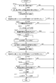
- FIG. 1 is a schematic configuration diagram of a driving support system according to the present embodiment.
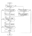
- FIG. 2 is a flowchart showing vehicle speed control according to the present embodiment.
- FIG. 3 is a flowchart showing the lane center maintenance control of the present embodiment.
- FIG. 4 is a diagram showing lane change control when the driver starts a winker operation as a trigger.
- FIG. 5 is a flowchart showing lane change control when the driver starts a winker operation as a trigger.
- FIG. 6 is a diagram showing lane change control by the overtaking support function.
- FIG. 7 is a flowchart showing lane change control by the overtaking support function.
- FIG. 8 is a diagram showing lane change control by the route traveling support function.
- FIG. 1 is a schematic configuration diagram of a driving support system according to the present embodiment.
- FIG. 2 is a flowchart showing vehicle speed control according to the present embodiment.
- FIG. 3 is a flowchart showing the lane center maintenance control of the present embodiment
- FIG. 9 is a flowchart showing lane change control by the route traveling support function.
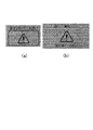
- FIG. 10 is a diagram showing an example of a warning screen for a forward gaze warning.
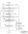
- FIG. 11 is a flowchart showing control of the notification operation of the forward gaze alarm.
- FIG. 12 is a diagram showing an example of a warning screen of the first hands-on alarm.
- FIG. 13 is a diagram showing an example of a warning screen for the second hands-on alarm.
- FIG. 14 is a flowchart showing the control of the notification operation of the hands-on alarm that is started when the mode is switched to the hands-on mode.
- FIG. 15 is a flowchart showing control of the notification operation of the hands-on alarm that is started when the forward gaze alarm is notified in the hands-off mode.
- FIG. 1 is a schematic configuration diagram of the driving support system 100 according to the first embodiment.
- the driver assistance system 100 includes an external sensor 1, an internal sensor 2, a navigation system 3, an in-vehicle device 4, a presentation device 5, an input device 6, and an actuator 7. And a controller 8.
- the driving support system 100 is mounted on a vehicle (own vehicle) 10 having an automatic driving function.
- the external sensor 1 is a detection device that detects an external situation that is peripheral information of the own vehicle 10.
- the external sensor 1 detects, for example, other vehicles around the own vehicle 10, lane markers, road types (motorways, general roads, etc.) and the like.
- the external sensor 1 includes an external camera 11 and a radar 12.
- the vehicle outside camera 11 is an imaging device that images the external situation of the own vehicle 10, and acquires imaging information about the external situation of the own vehicle 10.
- the vehicle exterior camera 11 is, for example, an around view monitor camera provided on the front, rear, and left and right doors of the vehicle interior of the vehicle 10, a front camera provided on the windshield of the vehicle interior or outside, and behind the vehicle 10.
- the rear camera to be installed.
- the radar 12 detects an object outside the own vehicle 10 using radio waves.
- the radio wave is, for example, millimeter wave. More specifically, the radar 12 transmits radio waves around the own vehicle 10 and receives the radio waves reflected by the object to detect the object.
- the radar 12 can acquire, for example, the distance or direction to an object as object information.
- the external sensor 1 outputs the acquired peripheral information (imaging information, object information) of the own vehicle 10 to the controller 8.
- the internal sensor 2 is a detection device that detects the state of the driver.
- the internal sensor 2 includes a driver monitor camera 21, a touch sensor 22, and the like.
- the driver monitor camera 21 is a monitor unit that captures the state of the driver and performs image processing, and detects the direction of the driver's face and the open / closed state of the eyes while driving.
- the driver monitor camera 21 is, for example, an infrared camera unit installed on the dashboard of the own vehicle 10, and includes an infrared camera 211 composed of an infrared emitting LED, an optical filter, a lens, and an image sensor, and an image processing chip 212. It is composed.
- the infrared camera 211 images the driver's face.
- the image processing chip 212 extracts the driver's facial organs (eyes, nose, mouth) from the driver image of the infrared camera 211 by pattern matching, and determines the orientation of the driver's face from the size and positional relationship of the facial organs.
- the image processing chip 212 acquires the determined driver's face orientation as face recognition information. Further, the image processing chip 212 determines the open / closed state of the eyes from the image of the peripheral portion of the driver's eyes, and acquires the open / closed state information as face recognition information.
- the touch sensor 22 is a detection device (detection means) that detects that the driver is holding his / her hand on the steering wheel.
- the touch sensor 22 is provided on the steering wheel, and the capacitance sensor detects that the driver is touching the steering wheel.
- the touch sensor 22 acquires as handle grip information whether or not it is detected that the driver is touching the steering wheel.
- the internal sensor 2 may include, for example, a seating sensor that detects that the driver is seated by a weight sensor, a seatbelt sensor that detects that the seatbelt is locked, and the like.
- the internal sensor 2 outputs the acquired face recognition information and steering wheel grip information to the controller 8 as driver status information.
- the navigation system 3 is a device that guides the driver to the destination set on the map by the driver or the like.
- the navigation system 3 includes a vehicle position detection device 31, a display 32, a speaker 33, and the like.
- the own vehicle position detection device 31 is a device for acquiring the position information of the own vehicle 10, and includes a GPS receiver (GNSS) 311, a gyro sensor 312, a vehicle speed sensor 313, and the like.
- the GPS receiver 311 periodically receives signals (GPS data) transmitted from GPS satellites.
- the gyro sensor 312 detects the orientation of the own vehicle 10.
- the vehicle speed sensor 313 detects the vehicle speed of the own vehicle 10.
- the own vehicle position detection device 31 outputs the received GPS data and the detected direction and vehicle speed of the own vehicle 10 to the controller 8 as position information of the own vehicle 10.
- the controller 8 constantly grasps the accurate current position, vehicle speed, and traveling direction of the own vehicle 10 from the received position information of the own vehicle 10. Further, the controller 8 calculates a target route to the destination of the own vehicle 10 based on the current position and the traveling direction of the own vehicle 10 and the map information of the map database (not shown). The calculated target route is transmitted to the display 32 and the speaker 33 as navigation information.
- the map database includes road speed limit information, and the navigation system 3 acquires information on the speed limit of the road on which the own vehicle 10 is traveling and outputs the information to the controller 8.
- the display 32 and the speaker 33 are devices that notify the driver of the target route information.
- the display 32 displays the target route information based on the navigation information from the controller 8.
- the speaker 33 outputs the target route information by voice based on the navigation information from the controller 8.
- the navigation system 3 may use information stored in a computer of a facility outside the vehicle such as an information processing center capable of communicating with the own vehicle 10. For example, the navigation system 3 may acquire traffic congestion information indicating road congestion and road speed limit information as navigation information from a computer of a facility via communication. Further, the processing executed by the navigation system 3 may be distributed and executed by the computer mounted on the own vehicle 10 and the computer outside the vehicle.
- the in-vehicle device 4 is various devices mounted on the vehicle and operates by the operation of the driver.
- the in-vehicle device 4 includes a steering wheel (handle) 41, an accelerator pedal 42, a brake pedal 43, and the like.
- the operation information is output to the controller 8.
- the controller 8 receives the operation information from the in-vehicle device 4, it transmits a command based on the operation information to the actuator 7 described later, and the actuator 7 executes the traveling control of the own vehicle 10 based on the command from the controller 8.
- the in-vehicle device 4 further includes devices such as a direction indicator (winker) 44, an audio device, an air conditioner, a hands-free switch, a power window, a wiper, a light, and a horn.
- a direction indicator (winker) 44 an audio device
- an air conditioner an air conditioner
- a hands-free switch a power window
- a wiper a light
- a horn a horn.
- the in-vehicle device 4 such as the winker 44 can be automatically started and stopped by the command of the controller 8 without the operation of the driver.
- the presentation device 5 is a device for notifying the driver of various notification information based on the control of the controller 8, which will be described later.
- the presentation device 5 includes a meter display 51, a head-up display 52, a speaker 53, and the like.
- the meter display 51 is a display device incorporated in the meter unit, and displays various notification information to the driver.
- the notification information includes running state information and warning information of the vehicle.
- the running state information of the vehicle includes, for example, the vehicle speed, fuel consumption and cruising distance of the own vehicle 10, ON / OFF of automatic driving control, type of driving control mode, speed limit sign, and status of other vehicles around the own vehicle 10.
- Lane information around the own vehicle 10 is displayed.
- the warning information for example, a forward gaze warning, a hands-on warning, an approach warning, and the like are displayed.
- the forward gaze alarm is displayed when it is determined that the driver is not gaze forward.
- the hands-on alarm is displayed when it is detected that the driver has released the steering wheel in the hands-on mode described later.
- the approach warning is displayed when it is determined that there is a risk of collision with another vehicle in front. The details of the warning information will be described later.
- the head-up display 52 is a display device that displays various notification information for the driver on the windshield.
- the notification information includes running state information and warning information of the vehicle.
- the head-up display 52 more easily displays the same information as the meter display 51.
- the speaker 53 is a notification device that outputs various notification information to the driver by voice.
- the speaker 53 notifies the driver of lane changes and various warning information during automatic driving, for example, by voice.
- the input device 6 is a switch operated by the driver, and is provided at a position on the steering wheel where the driver can easily operate, for example.
- the input device 6 includes a main switch 61, a set / coast switch 62, a resume / accelerate switch 63, a cancel switch 64, a speed limit support switch 65, an inter-vehicle distance adjustment switch 66, a lane change support switch 67, a steering control switch 68, and the like. ..
- the main switch 61 is a changeover switch for switching ON / OFF of the power supply of the driving support system 100.
- the set / coast switch 62 is a switch for starting vehicle speed control and reducing the set vehicle speed.
- the resume / accelerate switch 63 is a switch that has both a resume operation for restarting the operation at the set vehicle speed before the release and an acceleration operation for increasing the set vehicle speed after the vehicle speed control is released.
- the cancel switch 64 is a switch that cancels the operation of various controls related to automatic driving such as vehicle speed control and steering control.
- the speed limit support switch 65 is a switch for automatically setting the target vehicle speed to the speed limit during the vehicle speed control operation.
- the inter-vehicle distance adjustment switch 66 is a switch for changing the inter-vehicle distance (target inter-vehicle distance) to the preceding vehicle while the vehicle speed control is operating.
- the lane change support switch 67 determines that the driving support system 100 needs to change the lane of the own vehicle 10 while executing steering control, and when the presenting device 5 notifies the driver to change lanes, the driver lanes. A switch to allow changes to be made.
- the steering control switch 68 is, for example, a touch panel on the screen of the display 32 in the navigation system 3, and is a changeover switch for switching ON / OFF of the steering control function.
- the vehicle speed control and steering control will be described later.
- the input device 6 may be a device such as a push-type switch capable of manually inputting by the driver, a touch panel arranged on the display screen, a dial switch, or a microphone capable of inputting by the driver's voice. ..
- the information (input information) input to the input device 6 is output to the controller 8.
- the actuator 7 is a device that executes running control of the own vehicle 10 based on a command from the controller 8.
- the actuator 7 includes a drive actuator 71, a brake actuator 72, a steering actuator 73, and the like.
- the drive actuator 71 is a device for adjusting the driving force of the own vehicle 10.
- the drive actuator 71 is a throttle actuator that adjusts the amount of air supplied to the engine (throttle opening) and fuel for the engine. It consists of a fuel injection valve that adjusts the supply amount (fuel injection amount).
- the drive actuator 71 is a circuit (inverter, converter, etc.) capable of adjusting the electric power supplied to the motor. It is composed.
- the brake actuator 72 is a device that operates the brake system in response to a command from the controller 8 to adjust the braking force applied to the wheels of the own vehicle 10.
- the brake actuator 72 is composed of a hydraulic brake, a regenerative brake, or the like.
- the steering actuator 73 is composed of an assist motor or the like that controls the steering torque in the electric power steering system. By controlling the operation of the steering actuator 73 by the controller 8 and controlling the operation of the wheels, the steering control of the own vehicle 10 described later is executed.
- the controller 8 is composed of a computer equipped with a central processing unit (CPU), a read-only memory (ROM), a random access memory (R ⁇ M), and an input / output interface (I / O interface). By executing a specific program, the controller 8 executes a process for realizing the automatic driving control (driving support control) of the present embodiment. For example, the controller 8 executes vehicle speed control, steering control, control of notification operation of various warnings, and the like, which will be described below.
- the controller 8 may be configured by one computer or may be configured by a plurality of computers.
- the controller 8 is configured to be capable of communicating various signals with the external sensor 1, the internal sensor 2, the navigation system 3, the in-vehicle device 4, the presenting device 5, and the input device 6.
- the controller 8 receives various information acquired by the external sensor 1, the internal sensor 2, and the navigation system 3, as well as operation information from the in-vehicle device 4 and input information from the input device 6. Then, the controller 8 is programmed to acquire such information as the traveling information of the own vehicle 10 and appropriately operate the actuator 7 based on the traveling information to execute the driving support control of the present embodiment.
- the automatic driving control (driving support control) included in the driving support system 100 includes a vehicle speed control function and a steering control function.
- the vehicle speed control function is a function that controls the running speed of the vehicle so that it reaches the target value.
- vehicle speed control when there is no other vehicle in front, the vehicle is controlled to maintain the set target vehicle speed.
- control is performed so that the inter-vehicle distance is kept constant up to the target vehicle speed.
- the vehicle speed control function includes a function that automatically sets the legal speed as the target vehicle speed.
- FIG. 2 is a flowchart showing vehicle speed control according to this embodiment. All of the following vehicle speed controls are repeatedly executed by the controller 8.
- the driver can change the target vehicle speed at any time by operating the set / coast switch 62 or the resume / accelerate switch 63. Further, the driver can stop the automatic setting of the speed limit to the target vehicle speed at any time by turning off the speed limit support switch 65. Further, the driver can stop the vehicle speed control at any time by switching the main switch 61 to OFF, pressing the cancel switch 64, depressing the brake pedal 43, or the like.
- Vehicle speed control is control performed when the driving support system 100 is operating.
- the main switch 61 of the input device 6 is switched to ON, a start command of the driving support system 100 is transmitted to the controller 8.
- the controller 8 Upon receiving the start command, the controller 8 activates the driving support system 100.
- a vehicle speed control start command is transmitted to the controller 8.
- the controller 8 receives the vehicle speed control start command, the controller 8 starts the vehicle speed control.
- step S110 the controller 8 determines whether or not the navigation system 3 detects the speed limit of the road on which the own vehicle 10 is traveling, and the speed limit support switch 65 is turned on. Determine if it exists.
- the process proceeds to step S120.
- the speed limit on the road on which the own vehicle 10 is traveling may be detected by imaging a speed limit sign with the external sensor 1.
- step S120 the controller 8 sets the detected speed limit as the target vehicle speed.
- step S110 if the speed limit is not detected in step S110 or the speed limit support switch 65 is OFF, the process proceeds to step S121.
- step S121 the controller 8 sets the vehicle speed at the time when the set / coast switch 62 is pressed and the vehicle speed control is started as the target vehicle speed.
- step S130 the controller 8 controls the actuator 7 so that the vehicle speed of the own vehicle 10 becomes the set target vehicle speed.
- step S140 the controller 8 determines whether or not there is another vehicle in front of the own vehicle 10 based on the peripheral information of the own vehicle 10 acquired by the external sensor 1.
- step S140 If it is determined in step S140 that there is no other vehicle in front of the own vehicle 10, the controller 8 controls the actuator 7 so as to maintain the vehicle speed of the own vehicle 10 at the set target vehicle speed in step S150.
- step S140 determines that another vehicle is in front of the own vehicle 10
- the controller 8 shifts to the process of step S151.
- step S151 the controller 8 controls the actuator 7 so that the vehicle speed keeps the inter-vehicle distance constant with the set target vehicle speed as the upper limit speed.
- step S150 or step S151 the controller 8 returns to step S110 again. If the speed limit is not detected in step S110, or if the speed limit support switch 65 is OFF, the process proceeds to step S121. In this case, since the target vehicle speed has already been set, the controller 8 determines. Maintain the set target vehicle speed.
- the controller 8 displays information such as whether or not the vehicle speed control is executed, the target vehicle speed, the speed limit, and the like on the meter display 51 and the head-up display 52 of the presentation device 5. Further, for example, when the target vehicle speed is changed or a new speed limit is detected, characters are displayed on the meter display 51 and the head-up display 52, or the driver is notified by voice from the speaker 53. It may be set.
- the steering control function of the present embodiment includes a lane center maintenance (lane keep) support function and a lane change (lane change) support function.
- the lane center maintenance support function is a function that controls the steering so that the own vehicle 10 runs near the center of the lane and assists the driver in operating the steering wheel.
- the lane center maintenance control is started by switching the touch panel type steering control switch 68 of the navigation system 3 to ON while the vehicle speed control is being executed.
- Lane center maintenance control is started with the driver holding his hand on the steering wheel (hands mode), but the driver can take his hand off the steering wheel when certain conditions are met (hands-off mode).
- FIG. 3 is a flowchart showing the lane center maintenance control of the present embodiment. All of the following lane center maintenance controls are repeatedly executed by the controller 8.
- the driver can stop the lane center maintenance control at any time by turning off the steering control switch 68. Further, the driver can stop the lane center maintenance control and the vehicle speed control at any time by switching the main switch 61 to OFF, pressing the cancel switch 64, depressing the brake pedal 43, or the like.
- a start command for lane center maintenance control is transmitted to the controller 8.
- the controller 8 starts lane center maintenance control.
- the controller 8 displays on the meter display 51 and the head-up display 52 of the presentation device 5 that the steering control has been activated.
- step S210 the controller 8 acquires the traveling information of the own vehicle 10 and determines whether or not the lane center maintenance support function operating condition is satisfied based on the acquired traveling information. Specifically, for example, it is determined whether all of the following conditions are satisfied. (1) Lane markers on both sides are detected (2) The driver is holding his hand on the steering wheel (3) Driving near the center of the lane (4) The winker is not working (5) The wiper Not operating at high speed (6) If there is a high-precision map, there are no tollhouses, motorway exits, confluences, intersections, or lane reduction points within a predetermined distance (for example, about 200 m) ahead. All of these conditions are met. If so, the controller 8 activates the lane center maintenance support function in step S220. On the other hand, the controller 8 does not activate the lane center maintenance support function until all the above conditions are satisfied.
- the above-mentioned lane center maintenance support function operating conditions are examples, and are not limited to these conditions.
- the lane center maintenance support function is appropriately set so as to operate if certain predetermined conditions are satisfied depending on the situation. be able to.
- step S220 the lane center maintenance support function is activated, and the operation of the steering actuator 73 is controlled so that the own vehicle 10 travels in the center of the lane.
- the controller 8 activates the lane center maintenance support function, and notifies the driver to maintain the state in which the steering wheel is touched by the meter display 51 and the head-up display 52 of the presentation device 5. That is, the driver is notified that the driver is in the hands-on mode in which the driver executes driving assistance (automatic driving) with his / her hand on the steering wheel.
- step S230 the controller 8 determines whether or not the hands-off condition in which the driver may take his / her hand off the steering wheel is satisfied based on the traveling information of the own vehicle 10. Specifically, for example, it is determined whether all of the following conditions are satisfied.
- step S210 the controller 8 continues to operate the lane center maintenance support function and notify the hands-on mode in step S220. If the lane center maintenance support function operating condition is not satisfied in step S210, the controller 8 stops the operation of the lane center maintenance support function until the lane center maintenance support function operating condition is satisfied.
- step S240 the controller 8 notifies the driver that the driver may take his / her hand off the steering wheel by the meter display 51 and the head-up display 52 of the presenting device 5. That is, the driver is notified that the driver has switched to the hands-off mode in which driving assistance (automatic driving) is executed with the driver releasing his / her hand from the steering wheel.
- driving assistance automated driving
- hands-off conditions are examples, and are not limited to these conditions, and can be appropriately set so as to switch to the hands-off mode if certain predetermined conditions are satisfied depending on the situation.
- step S250 the controller 8 determines whether or not the condition for releasing the hands-off for switching from the hands-off mode to the hands-on mode is satisfied based on the traveling information. Specifically, for example, it is determined whether any one of the following conditions is satisfied. (1) Driving on a road other than a motorway (2) Driving on a two-way traffic section (3) Driving on a road without a high-precision map (4) Driving at a vehicle speed exceeding the speed limit (5)
- the GPS receiver (GNSS) 311 can no longer receive the signal.
- the driver did not turn to the front within a predetermined time (for example, 5 seconds) after the forward gaze alarm was activated (7). ) The driver cannot be detected by the driver monitor camera 21.
- a tollgate There is a tollgate, a motorway exit, a confluence, an intersection, or a point where the number of lanes is reduced within a predetermined distance (for example, 800 m) ahead.
- Vehicle speed When the vehicle is traveling at a speed of less than a predetermined speed (for example, about 40 km / h), there is a sharp curve (for example, a radius of curvature R of 100 m or less) within a predetermined distance (for example, 200 m) ahead.
- the vehicle speed is predetermined.
- the hands-off mode is not released until a predetermined time elapses after the forward gaze alarm is activated. That is, under the hands-off condition, the driver is facing forward (7) as a switching condition to the hands-off mode, whereas under the hands-off release condition, the hands-off mode is immediately canceled even if the driver is not facing forward. Not done. As a result, it is possible to prevent the hands-off mode from being canceled when, for example, the driver simply checks the left and right instead of looking aside.
- the controller 8 releases the hands-off mode and returns to step S210.
- the controller 8 continues the operation of the lane center maintenance support function in step S220 and notifies that the mode has been switched to the hands-on mode. If the lane center maintenance support function operating condition is not satisfied in step S210, the controller 8 stops the operation of the lane center maintenance support function until the lane center maintenance support function operating condition is satisfied.
- step S250 the controller 8 continues the hands-off mode (step S260) and returns to the process of step S250. That is, the controller 8 continues the hands-off mode until the hands-off release condition is satisfied.
- the above hands-off release conditions are examples, and are not limited to these conditions, and can be appropriately set so that the hands-off mode is canceled if certain predetermined conditions are satisfied depending on the situation.
- step S210 to step S260 are repeatedly executed until the driver stops the lane center maintenance control.
- the driver is started or switched by displaying characters on the meter display 51 and the head-up display 52 or by voice from the speaker 53. May be notified.
- the lane change support function is a function that controls the steering when the driver operates the winker 44 or when the driving support system 100 proposes a lane change and the driver presses the lane change support switch 67 to support the lane change.
- Lane change control is one of steering controls, and is driving support (automatic driving) control executed in a state where the driver puts his / her hand on the steering wheel, that is, in a hands-on mode.
- FIG. 4 is a diagram showing lane change control when the driver starts a winker operation as a trigger.
- the lane change operation (LCM) is started at a time t 2 several seconds after the start of the LCP, the lane change is performed, and the LCM is completed at a time t 3 within a few seconds from the start of the LCM.
- flasher 44 automatically or slotted in number within seconds t 4 is turned off, LCP is completed.
- the time from t 1 (winker lit) to t 2 (LCM start) and t 3 (LCM completed), and the time from t 3 (LCM completed) to t 4 (winker turned off) are all about several seconds.
- the present invention is not limited to this, and can be arbitrarily set depending on the situation.
- FIG. 5 is a flowchart showing lane change control when the driver starts a winker operation as a trigger. The following lane change control is executed by the controller 8.
- a lane change support process (LCP) start command is transmitted to the controller 8.
- the controller 8 determines in step S310 whether or not the LCP start condition is satisfied based on the travel information of the own vehicle 10. Specifically, for example, it is determined whether all of the following conditions are satisfied. (1) The driver puts his hand on the steering wheel within a predetermined time (for example, about 2 seconds) after the start of LCP. (2) The vehicle speed is equal to or higher than the predetermined speed (for example, about 60 km / h). (3) The destination to change lanes.
- a predetermined time for example, about 2 seconds
- the vehicle speed is equal to or higher than the predetermined speed (for example, about 60 km / h).
- the controller 8 cancels the lane change support process (LCP).
- step S320 the controller 8 starts the lane change support process (LCP) and controls the operation of the actuator 7 (particularly the steering actuator 73) so as to support the steering wheel operation required for the lane change. Further, the controller 8 displays information such as the start of the lane change support process (LCP) and the direction of the lane change on the meter display 51 and the head-up display 52 of the presentation device 5. In addition to the display on the meter display 51 and the head-up display 52, the driver may be notified that the lane change support process (LCP) has started by the voice from the speaker 53.
- LCP lane change support process
- LCP start conditions are examples, and are not limited to these conditions, and can be appropriately set so that LCP is started if certain predetermined conditions are satisfied depending on the situation.
- step S330 the controller 8 determines whether or not the lane change stop condition is satisfied based on the travel information of the own vehicle 10. Specifically, for example, it is determined whether any one of the following conditions is satisfied.
- the lane change operation could not be started within a predetermined time (for example, 5 seconds) after the start of LCP.
- Lane markers are not detected before starting LCM.
- step S340 the controller 8 controls the operation of the actuator 7 (particularly the steering actuator 73) and executes the lane change operation (LCM) of the own vehicle 10.
- the controller 8 turns off the winker 44 in step S350.
- the winker 44 goes out, the LCP ends.
- the blinker 44 may be turned off by a driver operation.
- lane change cancellation conditions are examples, and are not limited to these conditions, and can be appropriately set so that the lane change is canceled if certain predetermined conditions are met depending on the situation.
- the lane change support function proposed by the driving support system 100 includes an overtaking support function for overtaking a slow-speed vehicle and a route running support function for traveling according to a route to a destination.
- the overtaking support function is a function that controls the steering when a vehicle slower than the set speed is detected in front of the vehicle to support the overtaking operation.
- the route driving support function is a function that controls steering when the driver has set a destination and assists in changing lanes necessary for driving according to the route.
- FIG. 6 is a diagram showing lane change control by the overtaking support function.
- the lane change control by the overtaking support function is a lane change control that is started with the proposal of the driving support system 100 as a trigger when there is a vehicle in front of the vehicle whose speed is slower than the set speed.
- the presenting device 5 moves to the overtaking lane for the driver at time t 1-1 . You will be notified to change lanes.
- the winker 44 is turned on at the time t 1-3 within a few seconds, and the lane change support process ( LCP) is started.
- the lane change operation (LCM) is started within a few seconds from the start of the LCP at time t 1-4 , and the lane change to the overtaking lane is performed. Will be done.
- the lane change operation to the passing lane (LCM) is completed, at time t 1-6 of LCM after completion within a few seconds, turn signal 44 is turned off automatically or slotted , LCP is completed.
- t 1-2 when the lane change support switch 67 is pressed
- t 1-3 winker lights
- t 1-4 t 1-4
- t 1-5 LCM start
- the time to LCM completion) and the time from t 1-5 (LCM completion) to t 1-6 (winker off) are preferably about several seconds, but the time is not limited to this and can be set arbitrarily according to the situation. it can.
- the presenting device 5 notifies the driver to change lanes to the traveling lane at time t 2-1 .
- the winker 44 is turned on at time t 2-3 within a few seconds, and the lane change support process (LCP) starts again. Will be done.
- t 2-3 winker lights
- t 2-3 winker lights
- t 2-3 winker lights
- t 2-4 t 2-5
- the time to LCM completion) and the time from t 2-5 (LCM completion) to t 2-6 (winker off) are preferably about several seconds, but it is not limited to this and can be set arbitrarily according to the situation. it can.
- FIG. 7 is a flowchart showing lane change control by the overtaking support function. The following lane change control is executed by the controller 8.
- step S401 while the steering control is operating (the steering control switch 68 is ON), the controller 8 determines whether or not a vehicle slower than the set speed is detected in front of the own vehicle 10 based on the traveling information of the own vehicle 10. To do.
- step S402 the controller 8 determines whether or not the condition for proposing a lane change to the overtaking lane is satisfied based on the traveling information of the own vehicle 10. judge. Specifically, for example, it is determined whether all of the following conditions are satisfied.
- the vehicle speed is at least a predetermined speed (for example, about 60 km / h) (3) There is a space where the lane can be changed after 5 seconds (4) There is a lane in the direction of changing lanes (4) 5) The lane marker in the direction of changing lanes is a broken line (6)
- the vehicle is traveling on a straight line or a gentle curve (for example, the radius of curvature R is 250 m or more) (7)
- the target vehicle speed at which the vehicle speed of the own vehicle 10 is set It is slower than a predetermined speed (for example, 5 km / h) or more (8)
- the vehicle speed of the preceding vehicle is slower than a predetermined speed (for example, 10 km / h) or more than the set target vehicle speed (9)
- the distance between the own vehicle 10 and the preceding vehicle is When the inter-vehicle distance is less than the set inter-vehicle distance from the speed difference (for example, when the inter-vehicle distance is set to 50 m when traveling
- the speed of the preceding vehicle after changing lanes is faster than the preceding vehicle in the running lane by a predetermined speed (for example, about 5 km / h) or more If all of these conditions are met, it is necessary to change lanes. Presumed.
- the above conditions for proposing a lane change to an overtaking lane are examples, and are not limited to these conditions. It is presumed that a lane change is necessary if certain predetermined conditions are met depending on the situation. It can be set as appropriate.
- the controller 8 prompts the driver to change lanes by the notification of the presenting device 5 in step S403.
- step S404 when the controller 8 detects that the lane change support switch 67 has been pressed by the driver, the process proceeds to step S405. On the other hand, if the lane change support switch 67 is not pressed within a predetermined time, the controller 8 stops the lane change control.
- step S405 the controller 8 determines whether or not the lane change support process (LCP) start condition is satisfied based on the travel information of the own vehicle 10. Specifically, for example, it is determined whether all of the following conditions are satisfied. (1) The driver puts his hand on the steering wheel within a predetermined time after the lane change support switch 67 is pressed. (2) The vehicle speed is equal to or higher than the predetermined speed (for example, about 60 km / h). (3) The destination to change lanes.
- LCP lane change support process
- No vehicle is detected in (there is a space in the direction of changing lanes) (4) There is a lane in the direction of changing lanes (5)
- the lane marker in the direction of changing lanes is a broken line (6)
- the vehicle is traveling on a straight line or a gentle curve (for example, the radius of curvature R is 250 m or more) (7)
- the vehicle speed of the own vehicle 10 is slower than the set target vehicle speed (for example, 5 km / h) or more (8)
- the vehicle speed of the preceding vehicle is slower than the set target vehicle speed (for example, 10 km / h) or more (9)
- the speed of the preceding vehicle after changing lanes is faster than the preceding vehicle in the running lane by a predetermined speed (for example, about 5 km / h) or more.
- a predetermined speed for example, about 5 km / h
- step S406 the controller 8 turns on the winker 44 within a predetermined time within a few seconds after the driver presses the lane change support switch 67, and performs the lane change support process (LCP). ) Is started.
- the controller 8 controls the operation of the actuator 7 (particularly the steering actuator 73) so as to support the steering wheel operation required for the lane change.
- the controller 8 displays information such as the start of the lane change support process (LCP) and the direction of the lane change on the meter display 51 and the head-up display 52 of the presentation device 5.
- the driver may be notified that the lane change support process (LCP) has started by the voice from the speaker 53.
- LCP start conditions are examples, and are not limited to these conditions, and can be appropriately set so that LCP is started if certain predetermined conditions are satisfied depending on the situation.
- step S407 the controller 8 determines whether or not the lane change canceling condition is satisfied based on the traveling information of the own vehicle 10. Specifically, for example, it is determined whether any one of the following conditions is satisfied.
- the vehicle speed exceeded the speed limit before the start of LCP (2)
- the driver put his hand on the steering wheel and stepped on the accelerator pedal before the start of LCP (3)
- the predetermined time was exceeded after the start of LCP (LCP) LCM could not be started within the specified time after the start) (4)
- Hands-on alarm was activated (12) The driver When any one of these conditions for turning off the winker is satisfied, the controller 8 cancels the lane change control.
- the hands-on alarm is activated when the driver does not touch the steering wheel within a predetermined time after the lane change support switch 67 is pressed.
- step S408 the controller 8 controls the operation of the actuator 7 (particularly the steering actuator 73) to laterally move the own vehicle 10 and then change the lane to the overtaking lane. Perform an operation (LCM).
- the controller 8 After completing the lane change operation (LCM) to the overtaking lane, the controller 8 turns off the winker 44 and ends the LCP in step S409.
- the blinker 44 may be turned off by a driver operation.
- lane change cancellation conditions are examples, and are not limited to these conditions, and can be appropriately set so that the lane change is canceled if certain predetermined conditions are met depending on the situation.
- step S410 it is determined whether or not the condition for proposing a lane change to the traveling lane is satisfied. Specifically, for example, it is determined whether all of the following conditions are satisfied.
- the vehicle speed is at least a predetermined speed (for example, about 60 km / h) (2) There is a space where the lane can be changed after a predetermined time (3) There is a lane in the direction of changing lanes (4) A lane in the direction of changing lanes The marker is a broken line (5)
- the vehicle is traveling on a straight line or a gentle curve (for example, the radius of curvature R is 250 m or more) (6)
- the vehicle speed of the own vehicle 10 is a predetermined speed (for example, 5 km / h) from the set target vehicle speed.
- the above conditions for proposing a lane change to the driving lane are examples, and are not limited to these conditions. It is presumed that it is necessary to change the lane to return to the driving lane if certain predetermined conditions are met depending on the situation. It can be set as appropriate.
- step S411 the controller 8 prompts the driver to change lanes to the driving lane by the notification of the presenting device 5.
- step S412 when the controller 8 detects that the lane change support switch 67 has been pressed by the driver, the controller 8 shifts to the process of step S413. On the other hand, if the lane change support switch 67 is not pressed within a predetermined time after prompting the lane change, the controller 8 cancels the lane change control.
- step S413 the controller 8 determines whether or not the lane change support process (LCP) start condition is satisfied based on the traveling information of the own vehicle 10.
- the LCP start condition here is the same as in step S405. If even one of the LCP start conditions is not satisfied, the controller 8 cancels the lane change control to the traveling lane.
- step S414 the controller 8 turns on the winker 44 within a predetermined time after the driver presses the lane change support switch 67, and starts the lane change support process (LCP). ..
- the controller 8 controls the operation of the actuator 7 so as to support the steering wheel operation required for changing lanes, and the presenting device 5 informs the driver of information such as the start of LCP and the direction of changing lanes. Notify against.
- step S415 the controller 8 determines whether or not the lane change canceling condition is met based on the traveling information of the own vehicle 10.
- the lane change canceling condition is the same as in step S409. If any one of the lane change canceling conditions is satisfied, the controller 8 cancels the lane change control.
- step S416 the controller 8 laterally moves the own vehicle 10 and then executes a lane change operation (LCM) to the overtaking lane.
- LCD lane change operation
- the controller 8 turns off the winker 44 and ends the LCP in step S417.
- the blinker 44 may be turned off by a driver operation.
- the route driving support function is a function that controls steering when an occupant such as a driver sets a destination and supports a lane change necessary for driving according to the route.
- FIG. 8 is a diagram showing lane change control by the route traveling support function.
- the lane change control by the route driving support function triggers the proposal of the driving support system 100 when the driver reaches the lane change point necessary for driving according to the route when the destination is set by the navigation system 3. It is a lane change control started as.
- the time when the lane change point required for traveling according to the route is reached is, for example, when approaching an exit road, a branch road, or a lane reduction point.
- the presenting device 5 Will notify the driver to change lanes.
- the winker 44 is turned on at time 1-3 within a few seconds, and the lane change support process (LCP) is started. ..
- the steering control is executed.
- LCP start the predetermined condition is satisfied
- the lane change operation to the time t 1-4 within a few seconds (LCM) is started, the lane change is made, LCM at time t 1-5 within a few seconds after the LCM start Is completed.
- the winker 44 is turned off automatically or by the driver operation at time 1-6 , and the LCP is completed.
- t 1-2 when the lane change support switch 67 is pressed
- t 1-3 winker lights
- t 1-4 t 1-4
- t 1-5 LCM start
- the time to LCM completion) and the time from t 1-5 (LCM completion) to t 1-6 (winker off) are preferably about several seconds, but the time is not limited to this and can be set arbitrarily according to the situation. it can.
- FIG. 9 is a flowchart showing lane change control by the route driving support function. The following lane change control is executed by the controller 8.
- step S501 while the steering control is operating (the steering control switch 68 is ON), the controller 8 determines whether or not it is necessary to change lanes in order for the own vehicle 10 to travel according to the route to the set destination based on the travel information. Is determined. If lane change is not required, lane change control is stopped.
- the controller 8 determines in step S502 whether or not the proposed condition for changing the lane along the route is satisfied. Specifically, for example, it is determined whether all of the following conditions are satisfied. (1) The destination is set in the navigation system 3 (2) Hands-off mode (3) The vehicle speed is at least a predetermined speed (for example, about 60 km / h) (4) Change lane to the target lane Is possible (lane change is not prohibited) (5) If all the proposed conditions for changing lanes along a route traveling on a straight line or a gentle curve (for example, radius of curvature R is 250 m or more) are satisfied, it is necessary to change lanes along the route. Estimating, in step S503, the controller 8 prompts the driver to change lanes by notifying the presenting device 5.
- the proposed conditions for changing lanes along the above route are examples, and the conditions are not limited to these conditions, and it is necessary to change lanes along the route if certain conditions are met depending on the situation. It can be set as appropriate so that it can be estimated.
- step S504 when the controller 8 detects that the lane change support switch 67 has been pressed by the driver, the process proceeds to step S505. On the other hand, if the lane change support switch 67 is not pressed within a predetermined time, the controller 8 stops the lane change control.
- step S505 the controller 8 determines whether or not the lane change support process (LCP) start condition is satisfied based on the travel information of the own vehicle 10. Specifically, for example, it is determined whether all of the following conditions are satisfied. (1) The driver put his hand on the steering wheel within a predetermined time (for example, within about 2 seconds) after the lane change support switch 67 is pressed. (2) The vehicle speed is equal to or higher than the predetermined speed (for example, about 60 km / h). (3) The vehicle is not detected before changing lanes (there is a space in the direction of changing lanes).
- LCP lane change support process
- the lane marker in the direction of changing lanes is a broken line (6)
- the vehicle is traveling on a straight line or a gentle curve (for example, the radius of curvature R is 250 m or more). If even one is not satisfied, the controller 8 cancels the lane change control.
- step S506 the controller 8 lights the winker 44 within a predetermined time within a few seconds after the driver presses the lane change support switch 67, and performs the lane change support process (LCP).
- the controller 8 controls the operation of the actuator 7 (particularly the steering actuator 73) so as to support the steering wheel operation required for the lane change. Further, the controller 8 displays information such as the start of the lane change support process (LCP) and the direction of the lane change on the meter display 51 and the head-up display 52 of the presentation device 5.
- the driver may be notified that the lane change support process (LCP) has started by the voice from the speaker 53.
- LCP start conditions are examples, and are not limited to these conditions, and can be appropriately set so that LCP is started if certain predetermined conditions are satisfied depending on the situation.
- step S507 the controller 8 determines whether or not the lane change canceling condition is satisfied based on the traveling information of the own vehicle 10. Specifically, for example, it is determined whether or not any one of the following conditions is satisfied.
- the vehicle speed exceeded the speed limit before the start of LCP
- the driver put his hand on the steering wheel and stepped on the accelerator pedal before the start of LCP
- the predetermined time was exceeded after the start of LCP (LCP) LCM could not be started within the specified time after the start)
- the hands-on alarm is activated (12) The driver turns off the winker. When any one of these conditions is satisfied, the controller 8 determines. Stop lane change control. The hands-on alarm is activated when the driver does not touch the steering wheel within a predetermined time within a few seconds after the lane change support switch 67 is pressed.
- step S508 the controller 8 controls the operation of the actuator 7 (particularly the steering actuator 73), moves the own vehicle 10 laterally, and then performs the lane change operation (LCM). To execute.
- the controller 8 controls the operation of the actuator 7 (particularly the steering actuator 73), moves the own vehicle 10 laterally, and then performs the lane change operation (LCM). To execute.
- lane change cancellation conditions are examples, and are not limited to these conditions, and can be appropriately set so that the lane change is canceled if certain predetermined conditions are met depending on the situation.
- the controller 8 turns off the winker 44 and ends the LCP in step S509.
- the blinker 44 may be turned off by a driver operation.
- step S501 the controller 8 determines whether or not further lane change is necessary in order to travel according to the route based on the travel information of the own vehicle 10. If it is necessary to further change lanes, the control from step S502 to step S510 is performed again. On the other hand, if no further lane change is required, the lane change control is terminated.
- the vehicle speed limit control function and steering control function provided in the driving support system 100 have been described above, but these are examples of automatic driving control, and are not necessarily limited to the above configuration and flow. That is, the driving support system in which the control of the notification operation of various alarms described below is used is not limited to the driving support system that executes the above-mentioned automatic driving control.
- the warning information notified to the driver by the presenting device 5 includes forward gaze warning, first hands-on warning, second hands-on warning, steering control release warning, vehicle speed control / steering control release warning, approach warning, collision warning, and so on. It includes lane departure warnings.
- the forward gaze warning is notified when the driver determines that he is not gaze forward.
- the first hands-on alarm is notified when the driver detects that the driver has released the steering wheel in the hands-on mode.
- the second hands-on alarm is a state in which the driver does not hold the driver handle after the forward gaze alarm is notified and the driver is not gazing forward for a predetermined time, or after the first hands-on alarm is notified. Is notified when is continued for a predetermined time.
- the steering control release warning is notified when the steering control is released during the hands-off mode, and prompts the driver to operate the steering wheel.
- the vehicle speed control / steering control release warning is notified when the vehicle speed control and steering control are released during the hands-off mode, and prompts the driver to operate the steering wheel and pedals.
- the approach warning is issued when it is determined that there is a risk of collision with a vehicle in front.
- the collision warning is notified when the emergency brake (automatic brake control) is activated.
- the lane departure warning is notified when it is determined that the driver has approached the lane marker on the right or left side of the driving lane.
- the forward gaze warning is to gaze forward to the driver by sound or display. Is an alarm that requires.
- a warning screen as shown in FIG. 10 is displayed on the meter display 51 and the head-up display 52, and the driver is warned by the voice of the speaker 53.
- FIG. 10 (a) is an example of a warning screen displayed on the head-up display 52, and (b) is an example of a warning screen displayed on the meter display 51.
- the forward gaze warning In the hands-on mode, only the forward gaze warning is notified, but if the driver does not gaze forward even after a predetermined time (for example, about 5 seconds) has elapsed after the forward gaze warning is notified in the hands-off mode, The second hands-on alarm, which will be described later, is notified.
- a predetermined time for example, about 5 seconds
- a warning is always given to the driver when the driver is facing other than the front, for example, when the driver is facing the lane direction when a lane change is planned, or when the driver is simply checking.
- a warning will also be sent when the driver turns to the left or right. That is, an unnecessary warning is issued.
- the notification (warning) of the forward gaze warning is prohibited. That is, in the present embodiment, during the lane change control, if the driver is facing the lane change direction even if the driver is not gazing ahead, the forward gaze warning by the presenting device 5 is not notified. This reduces unnecessary warnings.
- the lighting direction (operating direction) of the winker 44 is estimated to be the lane change direction. In this way, the necessity of prohibiting the warning can be determined only from the information on the lighting direction of the winker 44 and the direction of the driver's face, and complicated processing is not required.
- the driving support system 100 proposes a lane change
- the driver confirms the lane change direction before the winker 44 is activated. Therefore, in the present embodiment, when the driving support system 100 proposes a lane change, the driver is facing the direction of the lane change proposed by the system even before the winker 44 is activated. , It was decided to prohibit the notification of the forward gaze warning. This further reduces unnecessary warnings.
- the forward gaze warning is not notified until the time when the driver is facing other than the front exceeds a predetermined time. That is, in the present embodiment, when the time when the driver is facing other than the front is short, such as when the driver is simply facing left and right for confirmation, that is, the time when the driver is facing other than the front is not continued for a predetermined time. As long as the forward gaze warning is not notified. This further reduces unnecessary warnings.
- FIG. 11 is a flowchart showing the control of the notification operation of the forward gaze alarm. The control of the following notification operations is repeatedly executed by the controller 8.
- step S601 the controller 8 determines whether or not the driver has closed his eyes for a predetermined time (for example, about 5 seconds) based on the face recognition information acquired by the driver monitor camera 21. ..
- step S608 the controller 8 notifies the driver of the forward gaze warning by the presentation device 5.
- the forward gaze warning is notified by the display on the meter display 51 and the head-up display 52 and the voice by the speaker 53.
- step S601 if it is determined in step S601 that the time when the driver has his eyes open or his eyes are closed does not exceed the predetermined time, the controller 8 shifts to the process of step S602.
- step S602 the controller 8 determines whether or not the driver's face orientation changes and the eyes open and close for a predetermined time (for example, about 60 seconds) based on the face recognition information acquired by the driver monitor camera 21. When there is no change in the direction of the driver's face and no opening / closing of the eyes for a predetermined time, the controller 8 presumes that the driver is not gazing forward and proceeds to the process of step S608. In step S608, the controller 8 notifies the driver of the forward gaze warning by display and voice by the presentation device 5.
- a predetermined time for example, about 60 seconds
- step S603 the controller 8 continuously advances forward (the traveling direction of the own vehicle 10) for a predetermined time (set as a first predetermined time, for example, about 5 seconds) based on the face recognition information acquired by the driver monitor camera 21. ) Is not facing. Specifically, when the following conditions are satisfied, the controller 8 determines that the driver is facing other than the front continuously for a predetermined time. (1) The driver faces the left and right predetermined angle (for example, about 20 degrees) or more outward for a predetermined time (for example, about 5 seconds) with respect to the traveling direction of the vehicle. (2) The vertical predetermined angle (for example) with respect to the horizontal direction of the vehicle. For example, when any of the above conditions is satisfied, the driver faces outward for a predetermined time (for example, about 5 seconds) or more, and the controller 8 determines that the driver is facing other than the front continuously for a predetermined time.
- a predetermined time for example, about 5 seconds
- step S603 If it is determined in step S603 that the driver is facing other than the front continuously for a predetermined time, the process proceeds to step S604. On the other hand, when it is determined that the time when the driver is facing forward or not facing forward exceeds a predetermined time, the forward gaze warning is not notified, and the controller 8 controls the notification operation of the forward gaze warning. To finish.
- the above conditions used to determine whether the driver is facing other than the front are examples, and are not limited to these conditions. If certain predetermined conditions are met depending on the situation, the driver faces other than the front. It can be appropriately set so as to determine that.
- step S604 the controller 8 determines whether or not lane change control is in progress based on the traveling information of the own vehicle 10.
- the lane change control is started when the driver performs a winker operation or when the driving support system 100 proposes a lane change. Therefore, the controller 8 determines the lane depending on whether the winker 44 operation is detected based on the operation information of the in-vehicle device 4 in the driving information of the own vehicle 10 and whether the driving support system 100 proposes the lane change to the driver. Determines whether change control is in progress.
- step S604 If it is determined in step S604 that the lane change control is not in progress, the controller 8 shifts to the process of step S608 and notifies the driver of the forward gaze warning by the display and voice of the presenting device 5.
- step S604 determines whether or not the driver is facing a lane change based on the traveling information of the own vehicle 10.
- the controller 8 estimates that the lighting direction of the winker 44 is the lane change direction.
- the controller 8 sets the direction of the lane to be changed proposed by the driving support system 100 as the lane change direction.
- the orientation of the driver's face is determined based on the face recognition information acquired by the driver monitor camera 21.
- step S605 If it is determined in step S605 that the driver is not facing the lane change direction, the controller 8 shifts to the process of step S608 and notifies the driver of the forward gaze warning by the display and voice of the presentation device 5.
- step S605 if it is determined in step S605 that the driver is facing the lane change direction, the controller 8 does not notify the driver of the forward gaze warning and proceeds to the process of step S606.
- step S606 the controller 8 determines whether or not the driver is continuously facing the lane change direction for a predetermined time (set as a second predetermined time) based on the traveling information of the own vehicle 10.
- the controller 8 shifts to the process of step S608 and notifies the forward gaze warning. This is because even if the driver is facing a lane change direction, if it exceeds a certain period of time, it is as dangerous as driving aside.
- the predetermined time (second predetermined time) here is set to be longer than the predetermined time (first predetermined time, for example, about 5 seconds) in step S603.
- step S606 If it is detected in step S606 that the driver turns his face forward within a predetermined time (second predetermined time), the controller 8 prohibits the notification of the forward gaze warning in step S607.
- the controller 8 detects that the winker 44 has been activated, and if the driver is facing the lane change direction after the winker 44 is activated, a forward caution warning is issued. Prohibit notification (warning).
- the controller 8 determines whether or not the lane change is necessary, determines that the lane change is necessary, and notifies the driver of the lane change, that is, when the driving support system 100 proposes the lane change, the driver is notified. If the driver is facing the lane change direction after notifying the lane change, the notification (warning) of the forward caution warning is prohibited.
- step S609 After notifying the forward gaze alarm in step S608, the controller 8 determines in step S609 whether or not it is in the hands-off mode. In the hands-off mode, the process shifts to the control of the hands-on alarm notification operation (step S810) described later. On the other hand, in the hands-on mode (the driver is holding his / her hand on the steering wheel), the controller 8 stops the notification of the forward gaze warning when it detects that the driver has gazed at the front in step S610.
- the control of the notification operation of the forward gaze alarm it is based on whether the driver has closed his eyes, whether the driver's face direction changes and the eyes do not open and close for a predetermined time, and whether the driver is facing forward. It is determined whether the driver is looking ahead.
- the conditions for determining whether or not the driver is gazing ahead are not limited to these, and it may be appropriately set so that the driver determines that the driver is not gazing ahead if certain predetermined conditions are met depending on the situation. it can.
- step S601 (whether the driver has closed his eyes) or step S602 (whether the driver's face orientation changes and the eyes do not open or close for a predetermined time) may be omitted as appropriate, or steps S601, S602 and steps S603 to The processing order of S606 may be changed.
- the hands-on warning is a warning given during automatic driving (during steering control operation), and includes a first hands-on warning and a second hands-on warning.
- the first hands-on alarm is notified when it detects that the driver has released the steering wheel in the hands-on mode, and requests the driver to operate the steering wheel by display.
- the first hands-on alarm prompts the driver to operate the steering wheel by displaying a warning screen as shown in FIG. 12, for example, on the meter display 51 and the head-up display 52.
- FIG. 12 (a) is an example of a head-up display 52, and (b) is an example of a warning screen displayed on the meter display 51.
- the second hands-on alarm is when the driver is not gazing forward for a predetermined time (fourth predetermined time, for example, about 5 seconds) after the forward gaze alarm is notified, or the first hands-on alarm is given. Is notified when the driver does not have a handle for a predetermined time (fourth predetermined time, for example, about 5 seconds).
- the second hands-on alarm requires the driver to operate the steering wheel by displaying, sounding, and alarming the brake (relaxing the brake multiple times for a short time).
- the warning screen as shown in FIG. 13 displays the meter display 51 and the head-up display 52, and the driver is urged to operate the steering wheel by the voice of the speaker 53 and the slow braking (alarm brake) for a short time.
- (a) is an example of a head-up display 52
- (b) is an example of a warning screen displayed on the meter display 51.
- the second hands-on alarm is always notified after the front gaze warning is notified, in the hands-off mode, even when the driver gazes forward immediately after the front gaze warning is notified.
- the second hands-on warning is notified. That is, an unnecessary warning is issued. Therefore, in the present embodiment, in the hands-off mode, the driver gazes forward within a predetermined time (third predetermined time) shorter than the fourth predetermined time even after the forward gaze warning is notified. In that case, it was decided not to notify the second hands-on alarm. That is, as described above, when the forward gaze alarm is notified in the hands-off mode, the hands-off mode is not released if the driver gazes ahead within a predetermined time.
- the hands-off mode is performed if the driver gazes at the front within a predetermined time (third predetermined time) even after the forward gaze warning is notified. It is not released and the second hands-on alarm is not notified. This further reduces unnecessary warnings.
- the control of the notification operation of the hands-on alarm is started when the mode is switched to the hands-on mode (or the steering control is started and the hands-on mode is started) and when the forward gaze alarm is notified in the hands-off mode.
- FIG. 14 is a flowchart showing the control of the notification operation of the hands-on alarm that is started when the mode is switched to the hands-on mode. The control of the following notification operations is repeatedly executed by the controller 8.
- step S710 the controller 8 determines whether or not the lane change control is being performed based on the running information.
- the lane change control is started when the driver performs an operation or when the driving support system 100 proposes a lane change. If the lane change control is not in progress (that is, the lane center maintenance control is in progress), the process proceeds to step S720.
- step S720 the controller 8 determines whether or not the driver touches the steering wheel within a predetermined time (for example, within about 5 seconds) in the hands-on mode based on the driving information (driver status information by the touch sensor 22).
- a predetermined time for example, within about 5 seconds
- the controller 8 ends the control of the notification operation of the hands-on alarm.
- the controller 8 notifies the first hands-on alarm in step S730.
- the first hands-on alarm prompts the driver to operate the steering wheel by displaying the display on the presentation device 5.
- step S740 the controller 8 receives the driver within a predetermined time (for example, within about 5 seconds) after the notification of the first hands-on alarm based on the driving information of the own vehicle 10 (driver status information by the touch sensor 22). Determine if you have touched the handle.
- a predetermined time for example, within about 5 seconds
- step S740 if it is determined that the driver puts his / her hand on the steering wheel within a predetermined time after the notification of the first hands-on alarm, the controller 8 stops the first hands-on alarm.
- step S740 if the driver continuously releases his / her hand from the steering wheel for a predetermined time, the process proceeds to step S750 and the second hands-on alarm is notified.
- the second hands-on alarm is given by display, voice, and alarm brake. That is, the controller 8 prompts the driver to operate the steering wheel by notifying the driver by the display and voice of the presenting device 5 and by controlling the brake actuator 72 to operate the brake a plurality of times.
- step S760 the controller 8 determines whether or not the driver touches the steering wheel within a predetermined time (for example, within about 5 seconds) based on the driving information (driver status information by the touch sensor 22).
- a predetermined time for example, within about 5 seconds
- the controller 8 stops the second hands-on alarm.
- step S760 determines whether the driver has continuously released his hand from the steering wheel for a predetermined time. If it is determined in step S760 that the driver has continuously released his hand from the steering wheel for a predetermined time, the controller 8 controls the brake actuator 72 in step S770 to decelerate the own vehicle 10 and forcibly stop the vehicle.
- step S804 the controller 8 touches the steering wheel within a predetermined time (fifth predetermined time, for example, within about 5 seconds) based on the driving information (driver status information by the touch sensor 22). Judge whether or not. When the driver puts his / her hand on the steering wheel (operates the steering wheel) within the predetermined time, the controller 8 stops the second hands-on alarm.
- a predetermined time for example, within about 5 seconds
- step S710 If it is determined in step S710 that the controller 8 is in lane change control, the process proceeds to step S721.
- step S721 the controller 8 determines whether or not the driver touches the steering wheel within a predetermined time (for example, within about 2 seconds) after the start of the lane change support process (LCP) based on the driving information. If the driver touches the steering wheel within a predetermined time after the start of the LCP, the controller 8 ends the control of the hands-on alarm notification operation.
- a predetermined time for example, within about 2 seconds
- step S722 the controller 8 notifies the first hands-on alarm and cancels the lane change control.
- step S722 the controller 8 then shifts to the process of step S740, and based on the traveling information of the own vehicle 10, the controller 8 is within a predetermined time (for example, after the notification of the first hands-on warning). Within about 5 seconds) it is determined whether the driver has touched the steering wheel. If the driver continuously releases his / her hand from the steering wheel for a predetermined time, the process proceeds to step S750, and the second hands-on alarm is notified. When the driver releases the steering wheel continuously for a predetermined time even when the second hands-on alarm is notified, the controller 8 forcibly stops the own vehicle 10 (step S770).
- FIG. 15 is a flowchart showing the control of the notification operation of the hands-on alarm that is started when the forward gaze alarm is notified in the hands-off mode.
- the case where the forward gaze warning is notified in the hands-off mode is a case where it is determined in the hands-off mode in step S609 of FIG.
- the controller 8 repeatedly executes the control of the following notification operations.
- step S810 the controller 8 moves the driver forward within a predetermined time after the forward gaze warning is notified based on the face recognition information acquired by the driver monitor camera 21. It is determined whether or not (the traveling direction of the own vehicle 10) is watched. Whether or not the driver gazes ahead is determined by whether the driver has changed the direction of his face in the direction of travel of the vehicle, whether his eyes have been closed for a predetermined time or more, and the like. If the driver changes the direction of the face in the direction of travel and the eyes are not closed for a predetermined time or more, it is determined that the driver is looking forward.
- step S810 when the driver gazes forward within a predetermined time (third predetermined time), the controller 8 stops the forward gaze alarm, prohibits the notification of the hands-on alarm, and continues the hands-off mode. .. On the other hand, in step S810, if the driver does not gaze at the front continuously for a predetermined time, the process proceeds to step S820.
- step S820 the controller 8 is within a predetermined time (within a fourth predetermined time) after a third predetermined time has elapsed after the forward gaze warning is notified based on the face recognition information acquired by the driver monitor camera 21. ) To determine whether the driver is looking ahead. When the driver gazes forward within the fourth predetermined time, the controller 8 switches to the hands-on mode in step S851 and stops the notification of the forward gaze warning.
- step 820 if the driver does not gaze forward within the fourth predetermined time, the process proceeds to step S830.
- step S830 the controller 8 notifies the driver of the second hands-on alarm.
- the second hands-on alarm is performed by the display and voice of the presentation device 5 and the alarm brake.
- step S840 the controller 8 touches the steering wheel within a predetermined time (fifth predetermined time, for example, within about 5 seconds) based on the driving information (driver status information by the touch sensor 22). Judge whether or not.
- the controller 8 stops the forward gaze alarm and the second hands-on alarm in step S851 and continues the automatic operation in the hands-on mode.
- step S840 when it is determined that the driver has continuously released the steering wheel for a predetermined time (fifth predetermined time), the controller 8 controls the brake actuator 72 in step S850 to control the own vehicle 10. Decelerate and forcibly stop.
- the controller 8 acquires the state information of the driver during automatic driving (during steering control execution), and when the driver is facing other than the front based on the state information of the driver, the driver is notified. Give a forward gaze warning (warning). However, if the driver is facing the lane change direction, the forward gaze warning is prohibited. That is, even when the driver is facing other than the front, the forward gaze warning is not notified (warning) when the driver is facing the lane change direction. This reduces unnecessary warnings. In addition, the necessity of prohibiting the forward gaze warning (warning) is determined only from the direction of lane change and the driver's status information (direction of the driver's face), and complicated processing is required to prohibit the warning. do not do. Therefore, it is possible to provide a driving support method and a driving support system that can reduce unnecessary warnings by a simple method.
- the driving support system 100 issues a forward gaze warning (warning) when the driver is facing a direction other than the front and the lane change direction when changing lanes. If all forward gaze warnings (warnings) are prohibited when the driver is facing a direction other than the front when changing lanes, the warning is also prohibited when the driver is facing a direction other than the front or the lane change direction.
- the driving support system 100 of the present embodiment gives a forward gaze warning (warning) to a sideways act in which the driver turns to a direction other than the front and the lane change direction even when the lane is changed. As a result, it is possible to prevent the driver from looking aside in a direction other than the front and the lane change direction, as compared with the case where all warnings are prohibited when changing lanes.
- the driving support system 100 detects the operating state of the winker 44 and prohibits a forward gaze warning (warning) when the driver is facing the lighting (operating) direction of the winker 44.
- a forward gaze warning warning
- the necessity of prohibiting the forward gaze warning (warning) is determined only from the lighting direction of the winker 44 and the driver's state information (direction of the driver's face), and complicated processing is performed to determine whether or not the warning is prohibited. do not need. Therefore, unnecessary warnings can be reduced by a simpler method.
- the driving support system 100 issues a forward gaze warning (warning) when the driver is facing a direction other than the front and the winker lighting direction when the winker 44 is lit.
- a forward gaze warning warning
- the driver it is possible to prevent the driver from looking aside in a direction other than the forward direction and the winker lighting direction, as compared with the case where all warnings are prohibited when the winker is lit.
- the driving support system 100 determines whether or not the vehicle needs to change lanes, and proposes (notifies) the driver to change lanes when it is determined that the vehicle needs to change lanes. Then, after notifying the driver of the lane change, if the driver is facing the lane change direction, the forward gaze warning (warning) is prohibited.
- the driving support system 100 proposes a lane change in this way, the forward gaze warning (warning) is prohibited if the driver is facing the lane change direction even before the winker 44 is turned on. Therefore, unnecessary warnings can be further reduced.
- the driving support system 100 issues a forward gaze warning (warning) to the driver when the driver drives the vehicle in a direction other than the front for the first predetermined time or longer.
- the forward gaze warning is not notified until the time when the driver is facing other than the front becomes the first predetermined time or more. Therefore, it is possible to prevent the warning from being given when the driver is facing other than the front for a short time, for example, when the driver is facing left and right for confirmation. That is, unnecessary warnings can be further reduced.
- the driving support system 100 does not notify the forward gaze warning until the time when the driver is facing the lane direction exceeds the second predetermined time, which is longer than the first predetermined time. (Prohibit warnings).
- the driving support system 100 includes a hands-off mode executed with the driver releasing his / her hand from the steering wheel and a hands-on mode executed with the driver holding his / her hand on the steering wheel. Then, in the hands-off mode, after issuing a forward gaze warning (warning) to the driver, if the driver turns to the front within a predetermined time, the hands-off mode is continued. In addition, when the driver turns to the front after a lapse of a predetermined time, the automatic driving is continued in the hands-on mode. In this way, after the forward gaze warning is notified, if the driver turns to the front within a predetermined time, the hands-off mode is continued, so that an unnecessary hands-on warning (warning prompting the steering wheel operation) is notified. Can be reduced. Therefore, unnecessary warnings can be further reduced.
- the driver assistance system 100 activates the brake a plurality of times to warn the driver if the driver is facing other than the front even after a predetermined time has elapsed after issuing a forward gaze warning (warning) to the driver. To do. If the driver releases the steering wheel after a predetermined time has passed after the brake is activated a plurality of times to warn the driver, the brake is further activated to forcibly stop the vehicle. As a result, it is possible to prevent an accident that may occur when the driver does not look ahead.
Abstract
Provided is a driving assistance method involving, by means of a controller, acquiring state information for a driver during autonomous driving travel and alerting the driver if it is determined on the basis of the state information for the driver that the driver is facing a direction other than the forward direction. In this driving assistance method, the alert is prohibited if the driver is facing a lane change direction during the autonomous driving travel.
Description
本発明は、運転支援方法及び運転支援システムに関する。
The present invention relates to a driving support method and a driving support system.
JP2018-151765Aには、ドライバが監視すべき箇所を所定時間目視していない場合に警告を発する視認支援装置が開示されている。この装置では、車外カメラで車両の周辺に存在する対象を検知し、検知した対象の種類を特定し、車内カメラでドライバの目視の状態を検知する。そして対象の種類とドライバの目視の状態に基づき、ドライバの目視が適切であったか否かを判定し、不適切と判定した場合に警告を発する。
JP2018-151765A discloses a visual recognition support device that issues a warning when the driver has not visually observed the part to be monitored for a predetermined time. In this device, the outside camera detects an object existing around the vehicle, the type of the detected object is specified, and the in-vehicle camera detects the visual state of the driver. Then, based on the type of the target and the visual condition of the driver, it is determined whether or not the visual inspection of the driver is appropriate, and if it is determined to be inappropriate, a warning is issued.
しかしながら、車外カメラで目視すべき箇所を検出するとともに車内カメラでドライバの目視箇所を検出して目視の適不適を判定し、警告の要否を判断するのは、判断が複雑になる。一方、車内カメラで検知したドライバの顔や目の向きのみで警告の要否を判断すると、不要な警告が発せられる恐れがある。
However, it is complicated to detect the part to be visually observed by the camera outside the vehicle and detect the visual part of the driver by the camera inside the vehicle to judge the suitability of the visual inspection and to judge the necessity of the warning. On the other hand, if the necessity of a warning is determined only by the direction of the driver's face or eyes detected by the in-vehicle camera, an unnecessary warning may be issued.
本発明は、上記課題に鑑み、簡易な方法で不要な警告を低減できる運転支援方法及び運転支援システムを提供することを目的とする。
In view of the above problems, an object of the present invention is to provide a driving support method and a driving support system capable of reducing unnecessary warnings by a simple method.
本発明の一態様によれば、コントローラにより、自動運転走行中のドライバの状態情報を取得し、ドライバの状態情報に基づいて、ドライバが前方以外を向いていると判定された場合にドライバに対し警告を行う運転支援方法が提供される。この運転支援方法では、自動運転走行中にドライバが車線変更方向を向いている場合には警告を禁止する。
According to one aspect of the present invention, the controller acquires the state information of the driver during automatic driving, and when it is determined that the driver is facing other than the front based on the state information of the driver, the driver A driving assistance method that gives a warning is provided. In this driving support method, a warning is prohibited when the driver is facing the lane change direction during automatic driving.
以下、図面等を参照しながら、本発明の実施形態について説明する。
Hereinafter, embodiments of the present invention will be described with reference to the drawings and the like.
(第1実施形態)
図1は、第1実施形態による運転支援システム100の概略構成図である。 (First Embodiment)
FIG. 1 is a schematic configuration diagram of thedriving support system 100 according to the first embodiment.
図1は、第1実施形態による運転支援システム100の概略構成図である。 (First Embodiment)
FIG. 1 is a schematic configuration diagram of the
図1に示すように、本実施形態に係る運転支援システム100は、外部センサ1と、内部センサ2と、ナビゲーションシステム3と、車載機器4と、提示装置5と、入力装置6と、アクチュエータ7と、コントローラ8とを備える。運転支援システム100は、自動運転機能を有する車両(自車両)10に搭載される。
As shown in FIG. 1, the driver assistance system 100 according to the present embodiment includes an external sensor 1, an internal sensor 2, a navigation system 3, an in-vehicle device 4, a presentation device 5, an input device 6, and an actuator 7. And a controller 8. The driving support system 100 is mounted on a vehicle (own vehicle) 10 having an automatic driving function.
外部センサ1は、自車両10の周辺情報である外部状況を検出する検出機器である。外部センサ1は、例えば自車両10周辺の他車両、レーンマーカー、道路種別(自動車専用道路、一般道路等)などを検出する。外部センサ1は、車外カメラ11及びレーダー12を含む。
The external sensor 1 is a detection device that detects an external situation that is peripheral information of the own vehicle 10. The external sensor 1 detects, for example, other vehicles around the own vehicle 10, lane markers, road types (motorways, general roads, etc.) and the like. The external sensor 1 includes an external camera 11 and a radar 12.
車外カメラ11は、自車両10の外部状況を撮像する撮像機器であり、自車両10の外部状況に関する撮像情報を取得する。車外カメラ11は、例えば、自車両10のフロント、リア、左右ドアの車室外側に設けられるアラウンドビューモニタカメラ、フロントガラスの車室内側または外側に設けられるフロントカメラ、及び自車両10の後方に設置されるリアカメラなどである。
The vehicle outside camera 11 is an imaging device that images the external situation of the own vehicle 10, and acquires imaging information about the external situation of the own vehicle 10. The vehicle exterior camera 11 is, for example, an around view monitor camera provided on the front, rear, and left and right doors of the vehicle interior of the vehicle 10, a front camera provided on the windshield of the vehicle interior or outside, and behind the vehicle 10. The rear camera to be installed.
レーダー12は、電波を利用して自車両10の外部の物体を検出する。電波は、例えばミリ波である。より詳細には、レーダー12は、電波を自車両10の周囲に送信し、物体で反射された電波を受信して物体を検出する。レーダー12は、例えば物体までの距離または方向を物体情報として取得することができる。
The radar 12 detects an object outside the own vehicle 10 using radio waves. The radio wave is, for example, millimeter wave. More specifically, the radar 12 transmits radio waves around the own vehicle 10 and receives the radio waves reflected by the object to detect the object. The radar 12 can acquire, for example, the distance or direction to an object as object information.
外部センサ1は、取得した自車両10の周辺情報(撮像情報、物体情報)をコントローラ8へ出力する。
The external sensor 1 outputs the acquired peripheral information (imaging information, object information) of the own vehicle 10 to the controller 8.
内部センサ2は、ドライバの状態を検知する検出機器である。内部センサ2は、ドライバモニタカメラ21、タッチセンサ22などを含む。
The internal sensor 2 is a detection device that detects the state of the driver. The internal sensor 2 includes a driver monitor camera 21, a touch sensor 22, and the like.
ドライバモニタカメラ21は、ドライバの状態を撮像し、画像処理を行うモニタユニットであり、走行中のドライバの顔の向き及び目の開閉状態を検出する。ドライバモニタカメラ21は、例えば自車両10のダッシュボード上に設置される赤外線カメラユニットであり、赤外線を発するLED、光学フィルタ、レンズ、イメージセンサから構成される赤外線カメラ211、及び画像処理チップ212で構成される。
The driver monitor camera 21 is a monitor unit that captures the state of the driver and performs image processing, and detects the direction of the driver's face and the open / closed state of the eyes while driving. The driver monitor camera 21 is, for example, an infrared camera unit installed on the dashboard of the own vehicle 10, and includes an infrared camera 211 composed of an infrared emitting LED, an optical filter, a lens, and an image sensor, and an image processing chip 212. It is composed.
赤外線カメラ211は、ドライバの顔を撮像する。画像処理チップ212は、赤外線カメラ211のドライバ画像からドライバの顔の器官(目、鼻、口)をパターンマッチングにより抽出し、顔の器官の大きさや位置関係からドライバの顔の向きを判定する。画像処理チップ212は、判定したドライバの顔の向きを顔認識情報として取得する。また、画像処理チップ212は、ドライバの目の周辺部の画像から、目の開閉状態を判定し、開閉状態情報も顔認識情報として取得する。
The infrared camera 211 images the driver's face. The image processing chip 212 extracts the driver's facial organs (eyes, nose, mouth) from the driver image of the infrared camera 211 by pattern matching, and determines the orientation of the driver's face from the size and positional relationship of the facial organs. The image processing chip 212 acquires the determined driver's face orientation as face recognition information. Further, the image processing chip 212 determines the open / closed state of the eyes from the image of the peripheral portion of the driver's eyes, and acquires the open / closed state information as face recognition information.
タッチセンサ22は、ドライバがハンドルに手を添えていることを検出する検出機器(検出手段)である。タッチセンサ22はハンドルに備えられ、静電容量センサによりドライバがハンドルに手を添えていることを検出する。タッチセンサ22は、ドライバがハンドルに手を添えていることが検出されたか否かをハンドル把持情報として取得する。
The touch sensor 22 is a detection device (detection means) that detects that the driver is holding his / her hand on the steering wheel. The touch sensor 22 is provided on the steering wheel, and the capacitance sensor detects that the driver is touching the steering wheel. The touch sensor 22 acquires as handle grip information whether or not it is detected that the driver is touching the steering wheel.
なお、内部センサ2はこの他、例えば重量センサでドライバが着座していることを検出する着座センサや、シートベルトがロックされていることを検出するシートベルトセンサなどを含んでもよい。
In addition to this, the internal sensor 2 may include, for example, a seating sensor that detects that the driver is seated by a weight sensor, a seatbelt sensor that detects that the seatbelt is locked, and the like.
内部センサ2は、取得した顔認識情報及びハンドル把持情報をドライバ状態情報としてコントローラ8へ出力する。
The internal sensor 2 outputs the acquired face recognition information and steering wheel grip information to the controller 8 as driver status information.
ナビゲーションシステム3は、ドライバ等によって地図上に設定された目的地までの案内をドライバに対して行う装置である。ナビゲーションシステム3は、自車位置検出装置31、ディスプレイ32、スピーカ33などを含む。
The navigation system 3 is a device that guides the driver to the destination set on the map by the driver or the like. The navigation system 3 includes a vehicle position detection device 31, a display 32, a speaker 33, and the like.
自車位置検出装置31は自車両10の位置情報を取得するための装置であり、GPS受信機(GNSS)311、ジャイロセンサ312、及び車速センサ313などを含む。GPS受信機311は、GPS衛星から送信される信号(GPSデータ)を周期的に受信する。ジャイロセンサ312は自車両10の方位を検出する。車速センサ313は自車両10の車速を検出する。
The own vehicle position detection device 31 is a device for acquiring the position information of the own vehicle 10, and includes a GPS receiver (GNSS) 311, a gyro sensor 312, a vehicle speed sensor 313, and the like. The GPS receiver 311 periodically receives signals (GPS data) transmitted from GPS satellites. The gyro sensor 312 detects the orientation of the own vehicle 10. The vehicle speed sensor 313 detects the vehicle speed of the own vehicle 10.
自車位置検出装置31は、受信されたGPSデータと、検出された自車両10の方位及び車速とを自車両10の位置情報としてコントローラ8へ出力する。コントローラ8は、受信した自車両10の位置情報から自車両10の正確な現在位置、車速及び進行方位を常時把握する。また、コントローラ8は、自車両10の現在位置及び進行方位と図示しない地図データベースの地図情報とに基づいて、自車両10の目的地までの目標ルートを算出する。算出した目標ルートは、ナビゲーション情報としてディスプレイ32及びスピーカ33に送信される。なお、地図データベースには、道路の制限速度情報が含まれており、ナビゲーションシステム3は自車両10が走行している道路の制限速度の情報を取得し、コントローラ8へ出力する。
The own vehicle position detection device 31 outputs the received GPS data and the detected direction and vehicle speed of the own vehicle 10 to the controller 8 as position information of the own vehicle 10. The controller 8 constantly grasps the accurate current position, vehicle speed, and traveling direction of the own vehicle 10 from the received position information of the own vehicle 10. Further, the controller 8 calculates a target route to the destination of the own vehicle 10 based on the current position and the traveling direction of the own vehicle 10 and the map information of the map database (not shown). The calculated target route is transmitted to the display 32 and the speaker 33 as navigation information. The map database includes road speed limit information, and the navigation system 3 acquires information on the speed limit of the road on which the own vehicle 10 is traveling and outputs the information to the controller 8.
ディスプレイ32及びスピーカ33は、ドライバに対して目標ルート情報の報知を行う機器である。ディスプレイ32は、コントローラ8からのナビゲーション情報に基づき、目標ルート情報を表示する。スピーカ33は、コントローラ8からのナビゲーション情報に基づき、目標ルート情報を音声出力する。
The display 32 and the speaker 33 are devices that notify the driver of the target route information. The display 32 displays the target route information based on the navigation information from the controller 8. The speaker 33 outputs the target route information by voice based on the navigation information from the controller 8.
なお、ナビゲーションシステム3は、自車両10と通信可能な情報処理センターなどの車両外部の施設のコンピュータに記憶された情報を用いてもよい。例えば、ナビゲーションシステム3は、施設のコンピュータから通信を介して道路の混雑を示す渋滞情報、道路の制限速度情報をナビゲーション情報として取得してもよい。また、ナビゲーションシステム3が実行する処理を、自車両10に搭載されるコンピュータと、車両外部のコンピュータとで分散して実行する構成をとっても良い。
Note that the navigation system 3 may use information stored in a computer of a facility outside the vehicle such as an information processing center capable of communicating with the own vehicle 10. For example, the navigation system 3 may acquire traffic congestion information indicating road congestion and road speed limit information as navigation information from a computer of a facility via communication. Further, the processing executed by the navigation system 3 may be distributed and executed by the computer mounted on the own vehicle 10 and the computer outside the vehicle.
車載機器4は、車両に搭載された各種機器であり、ドライバの操作により動作する。車載機器4は、ステアリングホイール(ハンドル)41、アクセルペダル42、ブレーキペダル43等を含む。これらの車載機器4がドライバにより操作された場合、その操作情報はコントローラ8に出力される。コントローラ8は車載機器4からの操作情報を受信すると、後述するアクチュエータ7に操作情報に基づく指令を送信し、アクチュエータ7はコントローラ8からの指令に基づき自車両10の走行制御を実行する。
The in-vehicle device 4 is various devices mounted on the vehicle and operates by the operation of the driver. The in-vehicle device 4 includes a steering wheel (handle) 41, an accelerator pedal 42, a brake pedal 43, and the like. When these in-vehicle devices 4 are operated by the driver, the operation information is output to the controller 8. When the controller 8 receives the operation information from the in-vehicle device 4, it transmits a command based on the operation information to the actuator 7 described later, and the actuator 7 executes the traveling control of the own vehicle 10 based on the command from the controller 8.
また、車載機器4は、さらに方向指示器(ウィンカ)44、オーディオ装置、エアーコンディショナー、ハンズフリースイッチ、パワーウィンドウ、ワイパ、ライト、クラクションなどの機器を含む。これらの機器がドライバにより操作された場合、その操作情報はコントローラ8に出力される。
Further, the in-vehicle device 4 further includes devices such as a direction indicator (winker) 44, an audio device, an air conditioner, a hands-free switch, a power window, a wiper, a light, and a horn. When these devices are operated by the driver, the operation information is output to the controller 8.
なお、後述する自動運転制御(運転支援制御)においては、ウィンカ44などの車載機器4は、ドライバの操作によらずにコントローラ8の指令により自動で作動及び停止させることもできる。
In the automatic driving control (driving support control) described later, the in-vehicle device 4 such as the winker 44 can be automatically started and stopped by the command of the controller 8 without the operation of the driver.
提示装置5は、後述するコントローラ8の制御に基づく各種報知情報をドライバに報知するための装置である。提示装置5は、メータディスプレイ51、ヘッドアップディスプレイ52、スピーカ53などを含む。
The presentation device 5 is a device for notifying the driver of various notification information based on the control of the controller 8, which will be described later. The presentation device 5 includes a meter display 51, a head-up display 52, a speaker 53, and the like.
メータディスプレイ51はメータ部に組み込まれた表示装置であり、ドライバに対する各種報知情報を表示する。報知情報は、車両の走行状態情報及び警告情報を含む。車両の走行状態情報としては、例えば自車両10の車速、燃費及び航続可能距離や、自動運転制御のON/OFF、運転制御モードの種類、制限速度標識、自車両10の周辺の他車両の状況、自車両10周辺のレーン情報等が表示される。警告情報としては、例えば前方注視警報、ハンズオン警報、接近警報等が表示される。前方注視警報は、ドライバが前方を注視していないと判定されたときに表示される。ハンズオン警報は、後述するハンズオンモードにおいてドライバがハンドルから手を離していることが検出された場合に表示される。接近警報は、前方の他車両に衝突する恐れがあると判断された場合に表示される。なお、警告情報の詳細は後述する。
The meter display 51 is a display device incorporated in the meter unit, and displays various notification information to the driver. The notification information includes running state information and warning information of the vehicle. The running state information of the vehicle includes, for example, the vehicle speed, fuel consumption and cruising distance of the own vehicle 10, ON / OFF of automatic driving control, type of driving control mode, speed limit sign, and status of other vehicles around the own vehicle 10. , Lane information around the own vehicle 10 is displayed. As the warning information, for example, a forward gaze warning, a hands-on warning, an approach warning, and the like are displayed. The forward gaze alarm is displayed when it is determined that the driver is not gaze forward. The hands-on alarm is displayed when it is detected that the driver has released the steering wheel in the hands-on mode described later. The approach warning is displayed when it is determined that there is a risk of collision with another vehicle in front. The details of the warning information will be described later.
ヘッドアップディスプレイ52はドライバに対する各種報知情報をフロントガラスに映し出す表示装置である。報知情報は、車両の走行状態情報及び警告情報を含む。ヘッドアップディスプレイ52は、メータディスプレイ51と同様の情報をより簡易に表示する。
The head-up display 52 is a display device that displays various notification information for the driver on the windshield. The notification information includes running state information and warning information of the vehicle. The head-up display 52 more easily displays the same information as the meter display 51.
スピーカ53は、ドライバに対する各種報知情報を音声出力する報知装置である。スピーカ53は、例えば自動運転走行時における車線変更や各種警告情報をドライバに対し、音声により報知する。
The speaker 53 is a notification device that outputs various notification information to the driver by voice. The speaker 53 notifies the driver of lane changes and various warning information during automatic driving, for example, by voice.
入力装置6は、ドライバにより操作されるスイッチであり、例えばステアリング上のドライバが操作しやすい位置等に設けられる。入力装置6は、メインスイッチ61、セット/コーストスイッチ62、リジューム/アクセラレートスイッチ63、キャンセルスイッチ64、制限速度支援スイッチ65、車間調整スイッチ66、車線変更支援スイッチ67、操舵制御スイッチ68等を含む。
The input device 6 is a switch operated by the driver, and is provided at a position on the steering wheel where the driver can easily operate, for example. The input device 6 includes a main switch 61, a set / coast switch 62, a resume / accelerate switch 63, a cancel switch 64, a speed limit support switch 65, an inter-vehicle distance adjustment switch 66, a lane change support switch 67, a steering control switch 68, and the like. ..
メインスイッチ61は、運転支援システム100の電源のON/OFFを切り替える切替スイッチである。
The main switch 61 is a changeover switch for switching ON / OFF of the power supply of the driving support system 100.
セット/コーストスイッチ62は、車速制御の開始及び設定車速を減少させるためのスイッチである。
The set / coast switch 62 is a switch for starting vehicle speed control and reducing the set vehicle speed.
リジューム/アクセラレートスイッチ63は、車速制御が解除された後、解除前の設定車速で作動を再開するリジューム操作と、設定車速を上昇させるアクセラレート操作を兼ねたスイッチである。
The resume / accelerate switch 63 is a switch that has both a resume operation for restarting the operation at the set vehicle speed before the release and an acceleration operation for increasing the set vehicle speed after the vehicle speed control is released.
キャンセルスイッチ64は、車速制御や操舵制御等の自動運転に関する各種制御の作動を解除するスイッチである。
The cancel switch 64 is a switch that cancels the operation of various controls related to automatic driving such as vehicle speed control and steering control.
制限速度支援スイッチ65は、車速制御作動中において、目標車速を自動的に制限速度に設定するためのスイッチである。
The speed limit support switch 65 is a switch for automatically setting the target vehicle speed to the speed limit during the vehicle speed control operation.
車間調整スイッチ66は、車速制御作動中において、先行車までの車間距離(目標車間距離)を変更するためのスイッチである。
The inter-vehicle distance adjustment switch 66 is a switch for changing the inter-vehicle distance (target inter-vehicle distance) to the preceding vehicle while the vehicle speed control is operating.
車線変更支援スイッチ67は、操舵制御を実行中、運転支援システム100が自車両10の車線変更が必要と判定し、提示装置5によりドライバに車線変更を促す報知がなされた場合に、ドライバが車線変更の実行を許可するためのスイッチである。
The lane change support switch 67 determines that the driving support system 100 needs to change the lane of the own vehicle 10 while executing steering control, and when the presenting device 5 notifies the driver to change lanes, the driver lanes. A switch to allow changes to be made.
操舵制御スイッチ68は、例えばナビゲーションシステム3におけるディスプレイ32の画面上のタッチパネルであり、操舵制御機能のON/OFFを切り替える切替スイッチである。
The steering control switch 68 is, for example, a touch panel on the screen of the display 32 in the navigation system 3, and is a changeover switch for switching ON / OFF of the steering control function.
なお、車速制御及び操舵制御については後述する。
The vehicle speed control and steering control will be described later.
入力装置6は、ドライバの手操作による入力が可能なプッシュ式スイッチやディスプレイ画面上に配置されたタッチパネルのほか、ダイヤルスイッチ、あるいはドライバの音声による入力が可能なマイクなどの装置であってもよい。
The input device 6 may be a device such as a push-type switch capable of manually inputting by the driver, a touch panel arranged on the display screen, a dial switch, or a microphone capable of inputting by the driver's voice. ..
入力装置6に入力された情報(入力情報)は、コントローラ8に出力される。
The information (input information) input to the input device 6 is output to the controller 8.
アクチュエータ7は、コントローラ8からの指令に基づいて自車両10の走行制御を実行する装置である。アクチュエータ7は、駆動アクチュエータ71、ブレーキアクチュエータ72、及びステアリングアクチュエータ73等を含む。
The actuator 7 is a device that executes running control of the own vehicle 10 based on a command from the controller 8. The actuator 7 includes a drive actuator 71, a brake actuator 72, a steering actuator 73, and the like.
駆動アクチュエータ71は、自車両10の駆動力を調節するための装置である。
The drive actuator 71 is a device for adjusting the driving force of the own vehicle 10.
特に、自車両10が走行駆動源としてのエンジンを搭載している内燃機関自動車である場合には、駆動アクチュエータ71はエンジンに対する空気の供給量(スロットル開度)を調節するスロットルアクチュエータ及びエンジンに対する燃料供給量(燃料噴射量)を調節する燃料噴射弁などで構成される。
In particular, when the own vehicle 10 is an internal combustion engine vehicle equipped with an engine as a traveling drive source, the drive actuator 71 is a throttle actuator that adjusts the amount of air supplied to the engine (throttle opening) and fuel for the engine. It consists of a fuel injection valve that adjusts the supply amount (fuel injection amount).
一方、自車両10が走行駆動源としてのモータを搭載しているハイブリッド車両または電気自動車である場合には、駆動アクチュエータ71はモータに供給する電力を調節可能な回路(インバータ及びコンバータなど)等で構成される。
On the other hand, when the own vehicle 10 is a hybrid vehicle or an electric vehicle equipped with a motor as a traveling drive source, the drive actuator 71 is a circuit (inverter, converter, etc.) capable of adjusting the electric power supplied to the motor. It is composed.
ブレーキアクチュエータ72は、コントローラ8からの指令に応じてブレーキシステムを操作し、自車両10の車輪へ付与する制動力を調節する装置である。ブレーキアクチュエータ72は、油圧ブレーキまたは回生ブレーキ等で構成される。
The brake actuator 72 is a device that operates the brake system in response to a command from the controller 8 to adjust the braking force applied to the wheels of the own vehicle 10. The brake actuator 72 is composed of a hydraulic brake, a regenerative brake, or the like.
ステアリングアクチュエータ73は、電動パワーステアリングシステムのうちステアリングトルクを制御するアシストモータ等で構成される。コントローラ8によりステアリングアクチュエータ73の動作を制御して、車輪の動作を制御することで、後述する自車両10の操舵制御を実行する。
The steering actuator 73 is composed of an assist motor or the like that controls the steering torque in the electric power steering system. By controlling the operation of the steering actuator 73 by the controller 8 and controlling the operation of the wheels, the steering control of the own vehicle 10 described later is executed.
コントローラ8は、中央演算装置(CPU)、読み出し専用メモリ(ROM)、ランダムアクセスメモリ(RΑM)及び入出力インタフェース(I/Oインタフェース)を備えたコンピュータで構成される。コントローラ8は特定のプログラムを実行することにより、本実施形態の自動運転制御(運転支援制御)を実現するための処理を実行する。例えば、コントローラ8は、以下で説明する車速制御、操舵制御、各種警報の報知動作の制御などを実行する。なお、コントローラ8は、一つのコンピュータで構成しても良いし、複数のコンピュータで構成しても良い。
The controller 8 is composed of a computer equipped with a central processing unit (CPU), a read-only memory (ROM), a random access memory (RΑM), and an input / output interface (I / O interface). By executing a specific program, the controller 8 executes a process for realizing the automatic driving control (driving support control) of the present embodiment. For example, the controller 8 executes vehicle speed control, steering control, control of notification operation of various warnings, and the like, which will be described below. The controller 8 may be configured by one computer or may be configured by a plurality of computers.
コントローラ8は、外部センサ1、内部センサ2、ナビゲーションシステム3、車載機器4、提示装置5及び入力装置6との間で各種信号を通信可能に構成される。コントローラ8は、外部センサ1、内部センサ2及びナビゲーションシステム3において取得された各種の情報、並びに車載機器4からの操作情報及び入力装置6からの入力情報を受信する。そしてコントローラ8は、これらの情報を自車両10の走行情報として取得し、走行情報に基づき適宜アクチュエータ7を操作して、本実施形態の運転支援制御を実行するようにプログラムされている。
The controller 8 is configured to be capable of communicating various signals with the external sensor 1, the internal sensor 2, the navigation system 3, the in-vehicle device 4, the presenting device 5, and the input device 6. The controller 8 receives various information acquired by the external sensor 1, the internal sensor 2, and the navigation system 3, as well as operation information from the in-vehicle device 4 and input information from the input device 6. Then, the controller 8 is programmed to acquire such information as the traveling information of the own vehicle 10 and appropriately operate the actuator 7 based on the traveling information to execute the driving support control of the present embodiment.
以下、本実施形態による運転支援システム100が備える自動運転制御(運転支援制御)及び各種警報の報知動作の制御について説明する。
Hereinafter, the automatic driving control (driving support control) provided in the driving support system 100 according to the present embodiment and the control of the notification operation of various alarms will be described.
運転支援システム100が備える自動運転制御(運転支援制御)には、車速制御機能及び操舵制御機能が含まれる。
The automatic driving control (driving support control) included in the driving support system 100 includes a vehicle speed control function and a steering control function.
車速制御機能は、車両の走行速度が目標値になるように制御する機能である。車速制御において、前方に他車両がいない場合には、設定された目標車速を維持するように制御する。一方、前方に車両がいる場合には、目標車速を上限として車間距離を一定に保つように制御する。
The vehicle speed control function is a function that controls the running speed of the vehicle so that it reaches the target value. In vehicle speed control, when there is no other vehicle in front, the vehicle is controlled to maintain the set target vehicle speed. On the other hand, when there is a vehicle in front, control is performed so that the inter-vehicle distance is kept constant up to the target vehicle speed.
また、車速制御機能は、法定速度を自動的に目標車速として設定する機能を含む。
In addition, the vehicle speed control function includes a function that automatically sets the legal speed as the target vehicle speed.
図2は、本実施形態の車速制御を示すフローチャートである。以下の車速制御はいずれもコントローラ8により繰り返し実行される。
FIG. 2 is a flowchart showing vehicle speed control according to this embodiment. All of the following vehicle speed controls are repeatedly executed by the controller 8.
なお、以下で説明する車速制御中、ドライバはセット/コーストスイッチ62またはリジューム/アクセラレートスイッチ63を操作することで、いつでも目標車速を変更することができる。また、ドライバは、制限速度支援スイッチ65をOFFにすることで、制限速度が自動的に目標車速に設定されるのをいつでも中止することができる。さらに、ドライバはメインスイッチ61をOFFに切り替えること、またはキャンセルスイッチ64を押すこと、或いはブレーキペダル43を踏むことなどにより、いつでも車速制御を中止させることができる。
During the vehicle speed control described below, the driver can change the target vehicle speed at any time by operating the set / coast switch 62 or the resume / accelerate switch 63. Further, the driver can stop the automatic setting of the speed limit to the target vehicle speed at any time by turning off the speed limit support switch 65. Further, the driver can stop the vehicle speed control at any time by switching the main switch 61 to OFF, pressing the cancel switch 64, depressing the brake pedal 43, or the like.
車速制御は、運転支援システム100が作動している際に行われる制御である。入力装置6のメインスイッチ61がONに切り替えられると、運転支援システム100の開始指令がコントローラ8に対して送信される。コントローラ8は、開始指令を受信すると、運転支援システム100を起動する。
Vehicle speed control is control performed when the driving support system 100 is operating. When the main switch 61 of the input device 6 is switched to ON, a start command of the driving support system 100 is transmitted to the controller 8. Upon receiving the start command, the controller 8 activates the driving support system 100.
運転支援システム100の作動中に、ドライバによりセット/コーストスイッチ62が押されると、車速制御の開始指令がコントローラ8に対して送信される。コントローラ8は、車速制御の開始指令を受信すると、車速制御を開始する。
When the set / coast switch 62 is pressed by the driver while the driving support system 100 is operating, a vehicle speed control start command is transmitted to the controller 8. When the controller 8 receives the vehicle speed control start command, the controller 8 starts the vehicle speed control.
車速制御が開始されると、ステップS110において、コントローラ8は、ナビゲーションシステム3が、自車両10が走行している道路の制限速度を検出しているか否か、及び制限速度支援スイッチ65がONであるか否かを判定する。ナビゲーションシステム3により制限速度が検出されており、且つ制限速度支援スイッチ65がONである場合、ステップS120の処理に移行する。
When the vehicle speed control is started, in step S110, the controller 8 determines whether or not the navigation system 3 detects the speed limit of the road on which the own vehicle 10 is traveling, and the speed limit support switch 65 is turned on. Determine if it exists. When the speed limit is detected by the navigation system 3 and the speed limit support switch 65 is ON, the process proceeds to step S120.
なお、自車両10が走行している道路の制限速度は、外部センサ1により制限速度標識を撮像して検出してもよい。
The speed limit on the road on which the own vehicle 10 is traveling may be detected by imaging a speed limit sign with the external sensor 1.
ステップS120において、コントローラ8は、検出された制限速度を目標車速として設定する。
In step S120, the controller 8 sets the detected speed limit as the target vehicle speed.
一方、ステップS110において、制限速度が検出されていない、または制限速度支援スイッチ65がOFFである場合、ステップS121の処理に移行する。
On the other hand, if the speed limit is not detected in step S110 or the speed limit support switch 65 is OFF, the process proceeds to step S121.
ステップS121において、コントローラ8は、セット/コーストスイッチ62が押されて車速制御が開始された際の車速を目標車速として設定する。
In step S121, the controller 8 sets the vehicle speed at the time when the set / coast switch 62 is pressed and the vehicle speed control is started as the target vehicle speed.
ステップS120またはステップS121において目標車速が設定されると、ステップS130において、コントローラ8は、自車両10の車速が設定された目標車速になるようにアクチュエータ7を制御する。
When the target vehicle speed is set in step S120 or step S121, in step S130, the controller 8 controls the actuator 7 so that the vehicle speed of the own vehicle 10 becomes the set target vehicle speed.
次にステップS140において、コントローラ8は、外部センサ1により取得された自車両10の周辺情報に基づき自車両10の前方に他車両がいないかを判定する。
Next, in step S140, the controller 8 determines whether or not there is another vehicle in front of the own vehicle 10 based on the peripheral information of the own vehicle 10 acquired by the external sensor 1.
ステップS140において、自車両10の前方に他車両がいないと判定すると、ステップS150において、コントローラ8は、自車両10の車速を設定されている目標車速に維持するようにアクチュエータ7を制御する。
If it is determined in step S140 that there is no other vehicle in front of the own vehicle 10, the controller 8 controls the actuator 7 so as to maintain the vehicle speed of the own vehicle 10 at the set target vehicle speed in step S150.
一方、ステップS140において、自車両10の前方に他車両がいると判定すると、コントローラ8は、ステップS151の処理に移行する。ステップS151において、コントローラ8は、設定されている目標車速を上限速度として、車間距離を一定に保つような車速になるようにアクチュエータ7を制御する。
On the other hand, if it is determined in step S140 that another vehicle is in front of the own vehicle 10, the controller 8 shifts to the process of step S151. In step S151, the controller 8 controls the actuator 7 so that the vehicle speed keeps the inter-vehicle distance constant with the set target vehicle speed as the upper limit speed.
ステップS150またはステップS151における処理を実行した後、コントローラ8は、再びステップS110に戻る。ステップS110において、制限速度が検出されていない、または制限速度支援スイッチ65がOFFである場合、ステップS121の処理に移行するが、この場合、既に目標車速が設定されているため、コントローラ8は、設定されている目標車速を維持する。
After executing the process in step S150 or step S151, the controller 8 returns to step S110 again. If the speed limit is not detected in step S110, or if the speed limit support switch 65 is OFF, the process proceeds to step S121. In this case, since the target vehicle speed has already been set, the controller 8 determines. Maintain the set target vehicle speed.
なお、コントローラ8は、車速制御の実行の有無、目標車速及び制限速度等の情報を提示装置5のメータディスプレイ51及びヘッドアップディスプレイ52に表示する。また、例えば目標車速が変更された場合や新しい制限速度が検出された場合等には、メータディスプレイ51及びヘッドアップディスプレイ52に文字表示をすることやスピーカ53による音声によりドライバに対し報知するように設定してもよい。
Note that the controller 8 displays information such as whether or not the vehicle speed control is executed, the target vehicle speed, the speed limit, and the like on the meter display 51 and the head-up display 52 of the presentation device 5. Further, for example, when the target vehicle speed is changed or a new speed limit is detected, characters are displayed on the meter display 51 and the head-up display 52, or the driver is notified by voice from the speaker 53. It may be set.
次に操舵制御機能について説明する。本実施形態の操舵制御機能には、車線中央維持(レーンキープ)支援機能及び車線変更(レーンチェンジ)支援機能が含まれる。
Next, the steering control function will be described. The steering control function of the present embodiment includes a lane center maintenance (lane keep) support function and a lane change (lane change) support function.
車線中央維持支援機能は、自車両10が車線の中央付近を走行するようにステアリングを制御し、ドライバのハンドル操作を支援する機能である。車線中央維持制御は、車速制御が実行されている状態において、ナビゲーションシステム3のタッチパネル式の操舵制御スイッチ68がONに切り替えられることで開始される。車線中央維持制御は、ドライバがハンドルに手を添えた状態(ハンズモード)で開始されるが、所定の条件が満たされるとドライバはハンドルから手を離すことができる(ハンズオフモード)。
The lane center maintenance support function is a function that controls the steering so that the own vehicle 10 runs near the center of the lane and assists the driver in operating the steering wheel. The lane center maintenance control is started by switching the touch panel type steering control switch 68 of the navigation system 3 to ON while the vehicle speed control is being executed. Lane center maintenance control is started with the driver holding his hand on the steering wheel (hands mode), but the driver can take his hand off the steering wheel when certain conditions are met (hands-off mode).
図3は、本実施形態の車線中央維持制御を示すフローチャートである。以下の車線中央維持制御はいずれもコントローラ8により繰り返し実行される。
FIG. 3 is a flowchart showing the lane center maintenance control of the present embodiment. All of the following lane center maintenance controls are repeatedly executed by the controller 8.
なお、以下で説明する車線中央維持制御中、ドライバは操舵制御スイッチ68をOFFにすることで、車線中央維持制御をいつでも中止することができる。また、ドライバはメインスイッチ61をOFFに切り替えること、またはキャンセルスイッチ64を押すこと、或いはブレーキペダル43を踏むこと等により、いつでも車線中央維持制御及び車速制御を中止させることができる。
During the lane center maintenance control described below, the driver can stop the lane center maintenance control at any time by turning off the steering control switch 68. Further, the driver can stop the lane center maintenance control and the vehicle speed control at any time by switching the main switch 61 to OFF, pressing the cancel switch 64, depressing the brake pedal 43, or the like.
車速制御機能の作動中に、ドライバにより操舵制御スイッチ68がONに切り替えられると、車線中央維持制御の開始指令がコントローラ8に対して送信される。コントローラ8は、開始指令を受信すると、車線中央維持制御を開始する。
When the steering control switch 68 is switched ON by the driver while the vehicle speed control function is operating, a start command for lane center maintenance control is transmitted to the controller 8. Upon receiving the start command, the controller 8 starts lane center maintenance control.
車線中央維持制御が開始されると、コントローラ8は、操舵制御が作動したことを提示装置5のメータディスプレイ51及びヘッドアップディスプレイ52に表示する。
When the lane center maintenance control is started, the controller 8 displays on the meter display 51 and the head-up display 52 of the presentation device 5 that the steering control has been activated.
続いてステップS210において、コントローラ8は、自車両10の走行情報を取得し、取得した走行情報に基づき、車線中央維持支援機能作動条件を満たしているか否かを判定する。具体的には、例えば以下の条件がすべて満たされているかを判定する。
(1)両側のレーンマーカーが検出されている
(2)ドライバがハンドルに手を添えている
(3)車線の中央付近を走行している
(4)ウィンカが作動していない
(5)ワイパが高速で作動していない
(6)高精度地図がある場合、前方所定の距離(例えば約200m)以内に料金所、自動車専用道路出口、合流、交差点、車線数減少地点がない
これらの条件がすべて満たされている場合、コントローラ8は、ステップS220において車線中央維持支援機能を作動させる。一方、上記の条件がすべて満たされるまで、コントローラ8は、車線中央維持支援機能を作動させない。 Subsequently, in step S210, thecontroller 8 acquires the traveling information of the own vehicle 10 and determines whether or not the lane center maintenance support function operating condition is satisfied based on the acquired traveling information. Specifically, for example, it is determined whether all of the following conditions are satisfied.
(1) Lane markers on both sides are detected (2) The driver is holding his hand on the steering wheel (3) Driving near the center of the lane (4) The winker is not working (5) The wiper Not operating at high speed (6) If there is a high-precision map, there are no tollhouses, motorway exits, confluences, intersections, or lane reduction points within a predetermined distance (for example, about 200 m) ahead. All of these conditions are met. If so, thecontroller 8 activates the lane center maintenance support function in step S220. On the other hand, the controller 8 does not activate the lane center maintenance support function until all the above conditions are satisfied.
(1)両側のレーンマーカーが検出されている
(2)ドライバがハンドルに手を添えている
(3)車線の中央付近を走行している
(4)ウィンカが作動していない
(5)ワイパが高速で作動していない
(6)高精度地図がある場合、前方所定の距離(例えば約200m)以内に料金所、自動車専用道路出口、合流、交差点、車線数減少地点がない
これらの条件がすべて満たされている場合、コントローラ8は、ステップS220において車線中央維持支援機能を作動させる。一方、上記の条件がすべて満たされるまで、コントローラ8は、車線中央維持支援機能を作動させない。 Subsequently, in step S210, the
(1) Lane markers on both sides are detected (2) The driver is holding his hand on the steering wheel (3) Driving near the center of the lane (4) The winker is not working (5) The wiper Not operating at high speed (6) If there is a high-precision map, there are no tollhouses, motorway exits, confluences, intersections, or lane reduction points within a predetermined distance (for example, about 200 m) ahead. All of these conditions are met. If so, the
なお、上記の車線中央維持支援機能作動条件は例示であり、これらの条件に限られるものではなく、状況に応じてある所定の条件を満たせば車線中央維持支援機能を作動させるように適宜設定することができる。
The above-mentioned lane center maintenance support function operating conditions are examples, and are not limited to these conditions. The lane center maintenance support function is appropriately set so as to operate if certain predetermined conditions are satisfied depending on the situation. be able to.
ステップS220において、車線中央維持支援機能を作動させ、自車両10が車線の中央を走行するようにステアリングアクチュエータ73の動作を制御する。また、コントローラ8は、車線中央維持支援機能を作動させるとともに、提示装置5のメータディスプレイ51及びヘッドアップディスプレイ52により、ドライバに対しハンドルに手を添えた状態を維持するよう報知する。即ち、ドライバに対し、ドライバがハンドルに手を添えた状態で運転支援(自動運転)を実行するハンズオンモードであることを報知する。
In step S220, the lane center maintenance support function is activated, and the operation of the steering actuator 73 is controlled so that the own vehicle 10 travels in the center of the lane. In addition, the controller 8 activates the lane center maintenance support function, and notifies the driver to maintain the state in which the steering wheel is touched by the meter display 51 and the head-up display 52 of the presentation device 5. That is, the driver is notified that the driver is in the hands-on mode in which the driver executes driving assistance (automatic driving) with his / her hand on the steering wheel.
次にステップS230において、コントローラ8は、自車両10の走行情報に基づき、ドライバがハンドルから手を離してもよいハンズオフ条件を満たしているか否かを判定する。具体的には、例えば以下の条件がすべて満たされているかを判定する。
(1)自動車専用道路を走行している
(2)対向車線と構造的に分離された道路を走行している
(3)高精度地図がある道路を走行している
(4)制限速度以下の車速で走行している
(5)GPS受信機(GNSS)311の受信信号が有効である
(6)ドライバがハンドルに手を添えている
(7)ドライバが前を向いている
(8)前方所定の距離(例えば800m)以内に料金所、自動車専用道路出口、合流、交差点、車線数減少地点がない
(9)前方所定の距離(例えば500m)以内に急なカーブ(例えば曲率半径Rが100m以下)がない
(10)トンネル内(例えばトンネル入り口から500mを超えた箇所)を走行していない
(11)アクセルペダルが踏まれていない
これらの条件がすべて満たされている場合、ステップS240の処理に移行する。 Next, in step S230, thecontroller 8 determines whether or not the hands-off condition in which the driver may take his / her hand off the steering wheel is satisfied based on the traveling information of the own vehicle 10. Specifically, for example, it is determined whether all of the following conditions are satisfied.
(1) Driving on a motorway (2) Driving on a road structurally separated from the oncoming lane (3) Driving on a road with a high-precision map (4) Below the speed limit Driving at vehicle speed (5) The received signal of the GPS receiver (GNSS) 311 is valid (6) The driver is holding his hand on the steering wheel (7) The driver is facing forward (8) Predetermined forward There are no toll stations, motorway exits, confluences, intersections, or points where the number of lanes is reduced within the distance (for example, 800 m). (9) A sharp curve (for example, radius of curvature R is 100 m or less) within a predetermined distance (for example, 500 m) ahead. ) Is not (10) The vehicle is not traveling in the tunnel (for example, a place exceeding 500 m from the tunnel entrance) (11) The accelerator pedal is not depressed When all of these conditions are satisfied, the process of step S240 is performed. Transition.
(1)自動車専用道路を走行している
(2)対向車線と構造的に分離された道路を走行している
(3)高精度地図がある道路を走行している
(4)制限速度以下の車速で走行している
(5)GPS受信機(GNSS)311の受信信号が有効である
(6)ドライバがハンドルに手を添えている
(7)ドライバが前を向いている
(8)前方所定の距離(例えば800m)以内に料金所、自動車専用道路出口、合流、交差点、車線数減少地点がない
(9)前方所定の距離(例えば500m)以内に急なカーブ(例えば曲率半径Rが100m以下)がない
(10)トンネル内(例えばトンネル入り口から500mを超えた箇所)を走行していない
(11)アクセルペダルが踏まれていない
これらの条件がすべて満たされている場合、ステップS240の処理に移行する。 Next, in step S230, the
(1) Driving on a motorway (2) Driving on a road structurally separated from the oncoming lane (3) Driving on a road with a high-precision map (4) Below the speed limit Driving at vehicle speed (5) The received signal of the GPS receiver (GNSS) 311 is valid (6) The driver is holding his hand on the steering wheel (7) The driver is facing forward (8) Predetermined forward There are no toll stations, motorway exits, confluences, intersections, or points where the number of lanes is reduced within the distance (for example, 800 m). (9) A sharp curve (for example, radius of curvature R is 100 m or less) within a predetermined distance (for example, 500 m) ahead. ) Is not (10) The vehicle is not traveling in the tunnel (for example, a place exceeding 500 m from the tunnel entrance) (11) The accelerator pedal is not depressed When all of these conditions are satisfied, the process of step S240 is performed. Transition.
一方、上記のハンズオフ条件が一つでも満たされていない場合、ステップS210に戻る。ステップS210において車線中央維持支援機能作動条件が満たされている場合、ステップS220においてコントローラ8は、車線中央維持支援機能の作動及びハンズオンモードの報知を継続する。ステップS210において車線中央維持支援機能作動条件が満たされていない場合は、コントローラ8は、車線中央維持支援機能作動条件が満たされるまで車線中央維持支援機能の作動を停止する。
On the other hand, if even one of the above hands-off conditions is not satisfied, the process returns to step S210. When the lane center maintenance support function operating condition is satisfied in step S210, the controller 8 continues to operate the lane center maintenance support function and notify the hands-on mode in step S220. If the lane center maintenance support function operating condition is not satisfied in step S210, the controller 8 stops the operation of the lane center maintenance support function until the lane center maintenance support function operating condition is satisfied.
ハンズオフ条件が満たされている場合、コントローラ8は、ステップS240において、提示装置5のメータディスプレイ51及びヘッドアップディスプレイ52により、ドライバに対しハンドルから手を離してもよいことを報知する。即ち、ドライバに対し、ドライバがハンドルから手を離した状態で運転支援(自動運転)を実行するハンズオフモードに切り替わったことを報知する。
When the hands-off condition is satisfied, in step S240, the controller 8 notifies the driver that the driver may take his / her hand off the steering wheel by the meter display 51 and the head-up display 52 of the presenting device 5. That is, the driver is notified that the driver has switched to the hands-off mode in which driving assistance (automatic driving) is executed with the driver releasing his / her hand from the steering wheel.
なお、上記のハンズオフ条件は例示であり、これらの条件に限られるものではなく、状況に応じてある所定の条件を満たせばハンズオフモードに切り替わるように適宜設定することができる。
Note that the above hands-off conditions are examples, and are not limited to these conditions, and can be appropriately set so as to switch to the hands-off mode if certain predetermined conditions are satisfied depending on the situation.
次にステップS250において、コントローラ8は、走行情報に基づき、ハンズオフモードからハンズオンモードに切り替わるハンズオフ解除条件に該当するか否かを判定する。具体的には、例えば以下の条件の何れか一つが成立しているかを判定する。
(1)自動車専用道路以外の道路を走行している
(2)対面通行区間を走行している
(3)高精度地図がない道路を走行している
(4)制限速度を超えた車速で走行している
(5)GPS受信機(GNSS)311が信号を受信できなくなった
(6)前方注視警報が作動した後、所定時間(例えば5秒)以内にドライバが前を向かなかった
(7)ドライバモニタカメラ21でドライバを検知できなくなった
(8)前方所定の距離(例えば800m)以内に料金所、自動車専用道路出口、合流、交差点、車線数減少地点のいずれかがある
(9)車速が所定の速度(例えば約40km/h)未満で走行している場合、前方所定の距離(例えば200m)以内に急なカーブ(例えば曲率半径Rが100m以下)がある
(10)車速が所定の速度(例えば約40km/h)以上で走行している場合、前方所定の距離(例えば200m)以内に急なカーブ(例えば曲率半径Rが170m以下)がある
(11)トンネル内(例えばトンネル入り口から500mを超えた箇所)を走行している
(12)ドライバがハンドルを持って、アクセルペダルを踏んだ
(13)接近警報が作動した
これらの条件の何れか一つが成立している場合、コントローラ8は、ハンズオンモードを解除する。 Next, in step S250, thecontroller 8 determines whether or not the condition for releasing the hands-off for switching from the hands-off mode to the hands-on mode is satisfied based on the traveling information. Specifically, for example, it is determined whether any one of the following conditions is satisfied.
(1) Driving on a road other than a motorway (2) Driving on a two-way traffic section (3) Driving on a road without a high-precision map (4) Driving at a vehicle speed exceeding the speed limit (5) The GPS receiver (GNSS) 311 can no longer receive the signal. (6) The driver did not turn to the front within a predetermined time (for example, 5 seconds) after the forward gaze alarm was activated (7). ) The driver cannot be detected by thedriver monitor camera 21. (8) There is a tollgate, a motorway exit, a confluence, an intersection, or a point where the number of lanes is reduced within a predetermined distance (for example, 800 m) ahead. (9) Vehicle speed When the vehicle is traveling at a speed of less than a predetermined speed (for example, about 40 km / h), there is a sharp curve (for example, a radius of curvature R of 100 m or less) within a predetermined distance (for example, 200 m) ahead. (10) The vehicle speed is predetermined. When traveling at a speed (for example, about 40 km / h) or higher, there is a sharp curve (for example, the radius of curvature R is 170 m or less) within a predetermined distance (for example, 200 m) ahead. (11) Inside the tunnel (for example, from the tunnel entrance) (12) The driver holds the steering wheel and depresses the accelerator pedal (13) The approach alarm is activated. If any one of these conditions is satisfied, the controller 8 Releases hands-on mode.
(1)自動車専用道路以外の道路を走行している
(2)対面通行区間を走行している
(3)高精度地図がない道路を走行している
(4)制限速度を超えた車速で走行している
(5)GPS受信機(GNSS)311が信号を受信できなくなった
(6)前方注視警報が作動した後、所定時間(例えば5秒)以内にドライバが前を向かなかった
(7)ドライバモニタカメラ21でドライバを検知できなくなった
(8)前方所定の距離(例えば800m)以内に料金所、自動車専用道路出口、合流、交差点、車線数減少地点のいずれかがある
(9)車速が所定の速度(例えば約40km/h)未満で走行している場合、前方所定の距離(例えば200m)以内に急なカーブ(例えば曲率半径Rが100m以下)がある
(10)車速が所定の速度(例えば約40km/h)以上で走行している場合、前方所定の距離(例えば200m)以内に急なカーブ(例えば曲率半径Rが170m以下)がある
(11)トンネル内(例えばトンネル入り口から500mを超えた箇所)を走行している
(12)ドライバがハンドルを持って、アクセルペダルを踏んだ
(13)接近警報が作動した
これらの条件の何れか一つが成立している場合、コントローラ8は、ハンズオンモードを解除する。 Next, in step S250, the
(1) Driving on a road other than a motorway (2) Driving on a two-way traffic section (3) Driving on a road without a high-precision map (4) Driving at a vehicle speed exceeding the speed limit (5) The GPS receiver (GNSS) 311 can no longer receive the signal. (6) The driver did not turn to the front within a predetermined time (for example, 5 seconds) after the forward gaze alarm was activated (7). ) The driver cannot be detected by the
ここでハンズオフ解除条件の(6)において、前方注視警報が作動した後、所定時間が経過するまではハンズオフモードは解除されない。即ちハンズオフ条件ではドライバが前方を向いていること(7)をハンズオフモードへの切替条件とするのに対し、ハンズオフ解除条件ではドライバが前方を向いていなくてもすぐにはハンズオフモードが解除されない。これにより、例えばドライバがわき見運転ではなく、単に左右を確認した場合等にハンズオフモードが解除されてしてしまうことを回避できる。
Here, in the hands-off release condition (6), the hands-off mode is not released until a predetermined time elapses after the forward gaze alarm is activated. That is, under the hands-off condition, the driver is facing forward (7) as a switching condition to the hands-off mode, whereas under the hands-off release condition, the hands-off mode is immediately canceled even if the driver is not facing forward. Not done. As a result, it is possible to prevent the hands-off mode from being canceled when, for example, the driver simply checks the left and right instead of looking aside.
ハンズオフ解除条件の何れか一つが成立している場合、コントローラ8は、ハンズオフモードを解除し、ステップS210に戻る。ステップS210において車線中央維持支援機能作動条件が満たされている場合、ステップS220においてコントローラ8は、車線中央維持支援機能の作動を継続するとともに、ハンズオンモードに切り替わったことを報知する。ステップS210において車線中央維持支援機能作動条件が満たされていない場合は、コントローラ8は、車線中央維持支援機能作動条件が満たされるまで車線中央維持支援機能の作動を停止する。
If any one of the hands-off release conditions is satisfied, the controller 8 releases the hands-off mode and returns to step S210. When the lane center maintenance support function operating condition is satisfied in step S210, the controller 8 continues the operation of the lane center maintenance support function in step S220 and notifies that the mode has been switched to the hands-on mode. If the lane center maintenance support function operating condition is not satisfied in step S210, the controller 8 stops the operation of the lane center maintenance support function until the lane center maintenance support function operating condition is satisfied.
一方、ステップS250においてハンズオフ解除条件が成立していない場合、コントローラ8は、ハンズオフモードを継続し(ステップS260)、ステップS250の処理に戻る。即ち、コントローラ8は、ハンズオフ解除条件が成立するまでハンズオフモードを継続する。
On the other hand, if the hands-off release condition is not satisfied in step S250, the controller 8 continues the hands-off mode (step S260) and returns to the process of step S250. That is, the controller 8 continues the hands-off mode until the hands-off release condition is satisfied.
なお、上記のハンズオフ解除条件は例示であり、これらの条件に限られるものではなく、状況に応じてある所定の条件を満たせばハンズオフモードが解除されるように適宜設定することができる。
Note that the above hands-off release conditions are examples, and are not limited to these conditions, and can be appropriately set so that the hands-off mode is canceled if certain predetermined conditions are satisfied depending on the situation.
上記のステップS210からステップS260までの処理は、ドライバが車線中央維持制御を中止させるまで繰り返し実行される。
The above processes from step S210 to step S260 are repeatedly executed until the driver stops the lane center maintenance control.
なお、車線中央維持制御が開始した場合やハンズオンモードとハンズオフモードとが切り替わった場合等に、メータディスプレイ51及びヘッドアップディスプレイ52への文字表示や、スピーカ53による音声によりドライバに対し開始や切替を報知してもよい。
When the lane center maintenance control is started or when the hands-on mode and the hands-off mode are switched, the driver is started or switched by displaying characters on the meter display 51 and the head-up display 52 or by voice from the speaker 53. May be notified.
次に、車線変更支援機能について説明する。
Next, the lane change support function will be explained.
車線変更支援機能は、ドライバがウィンカ44を操作した場合、または運転支援システム100が車線変更を提案し、ドライバが車線変更支援スイッチ67を押した場合にステアリングを制御し、車線変更を支援する機能である。車線変更制御は操舵制御の1つであり、ドライバがハンドルに手を添えた状態、即ちハンズオンモードで実行される運転支援(自動運転)制御である。
The lane change support function is a function that controls the steering when the driver operates the winker 44 or when the driving support system 100 proposes a lane change and the driver presses the lane change support switch 67 to support the lane change. Is. Lane change control is one of steering controls, and is driving support (automatic driving) control executed in a state where the driver puts his / her hand on the steering wheel, that is, in a hands-on mode.
図4は、ドライバによるウィンカ操作をトリガとして開始される場合の車線変更制御を示す図である。
FIG. 4 is a diagram showing lane change control when the driver starts a winker operation as a trigger.
図4に示すように、操舵制御作動中の時間t1においてドライバがウィンカ44を点灯させると、所定の条件を満たす場合、車線変更支援処理(LCP)が開始され、ステアリングの制御が実行される。
As shown in FIG. 4, when the driver turns on the turn signal 44 at time t 1 in the steering control operation, when a predetermined condition is satisfied, the lane change assist processing (LCP) is started, the control of the steering is performed ..
LCP開始後、所定の条件を満たすと、LCP開始から数秒後の時間t2において車線変更操作(LCM)が開始され、車線変更が行われ、LCM開始から数秒以内の時間t3においてLCMが完了する。
When a predetermined condition is satisfied after the start of the LCP, the lane change operation (LCM) is started at a time t 2 several seconds after the start of the LCP, the lane change is performed, and the LCM is completed at a time t 3 within a few seconds from the start of the LCM. To do.
LCM完了後、数秒以内の時間t4において自動またはドライバ操作によりウィンカ44が消灯され、LCPが完了する。
After LCM completed, flasher 44 automatically or slotted in number within seconds t 4 is turned off, LCP is completed.
なお、t1(ウィンカ点灯)からt2(LCM開始)及びt3(LCM完了)までの時間、t3(LCM完了)からt4(ウィンカ消灯)までの時間はいずれも数秒程度であることが好ましいが、これに限られず状況に応じて任意に設定できる。
The time from t 1 (winker lit) to t 2 (LCM start) and t 3 (LCM completed), and the time from t 3 (LCM completed) to t 4 (winker turned off) are all about several seconds. However, the present invention is not limited to this, and can be arbitrarily set depending on the situation.
図5は、ドライバによるウィンカ操作をトリガとして開始される場合の車線変更制御を示すフローチャートである。以下の車線変更制御は、いずれもコントローラ8により実行される。
FIG. 5 is a flowchart showing lane change control when the driver starts a winker operation as a trigger. The following lane change control is executed by the controller 8.
操舵制御作動中(操舵制御スイッチ68がONの状態)で、ドライバがウィンカ44を操作すると、車線変更支援処理(LCP)の開始指令がコントローラ8に対して送信される。
When the driver operates the winker 44 while the steering control is operating (the steering control switch 68 is ON), a lane change support process (LCP) start command is transmitted to the controller 8.
コントローラ8は、LCP開始指令を受信すると、ステップS310において、自車両10の走行情報に基づき、LCP開始条件を満たしているか否かを判定する。具体的には、例えば以下の条件がすべて満たされているかを判定する。
(1)LCP開始後、所定時間(例えば約2秒)以内にドライバがハンドルに手を添えた
(2)車速が所定の速度(例えば約60km/h)以上である
(3)車線変更する先に車両を検出していない(車線変更する方向にスペースがある)
(4)車線変更する方向に車線がある
(5)車線変更する方向のレーンマーカーが破線である
(6)直線または緩やかなカーブ(例えば曲率半径Rが250m以上)を走行している
(7)ドライバがウィンカ操作をしてから所定時間内(例えば約1秒以内)である
これらの条件がすべて満たされている場合、ステップS320においてコントローラ8は、車線変更支援処理(LCP)を開始する。 Upon receiving the LCP start command, thecontroller 8 determines in step S310 whether or not the LCP start condition is satisfied based on the travel information of the own vehicle 10. Specifically, for example, it is determined whether all of the following conditions are satisfied.
(1) The driver puts his hand on the steering wheel within a predetermined time (for example, about 2 seconds) after the start of LCP. (2) The vehicle speed is equal to or higher than the predetermined speed (for example, about 60 km / h). (3) The destination to change lanes. No vehicle is detected in (there is a space in the direction of changing lanes)
(4) There is a lane in the direction of changing lanes (5) The lane marker in the direction of changing lanes is a broken line (6) The vehicle is traveling on a straight line or a gentle curve (for example, the radius of curvature R is 250 m or more) (7) Within a predetermined time (for example, within about 1 second) after the driver operates the winker If all of these conditions are satisfied, thecontroller 8 starts the lane change support process (LCP) in step S320.
(1)LCP開始後、所定時間(例えば約2秒)以内にドライバがハンドルに手を添えた
(2)車速が所定の速度(例えば約60km/h)以上である
(3)車線変更する先に車両を検出していない(車線変更する方向にスペースがある)
(4)車線変更する方向に車線がある
(5)車線変更する方向のレーンマーカーが破線である
(6)直線または緩やかなカーブ(例えば曲率半径Rが250m以上)を走行している
(7)ドライバがウィンカ操作をしてから所定時間内(例えば約1秒以内)である
これらの条件がすべて満たされている場合、ステップS320においてコントローラ8は、車線変更支援処理(LCP)を開始する。 Upon receiving the LCP start command, the
(1) The driver puts his hand on the steering wheel within a predetermined time (for example, about 2 seconds) after the start of LCP. (2) The vehicle speed is equal to or higher than the predetermined speed (for example, about 60 km / h). (3) The destination to change lanes. No vehicle is detected in (there is a space in the direction of changing lanes)
(4) There is a lane in the direction of changing lanes (5) The lane marker in the direction of changing lanes is a broken line (6) The vehicle is traveling on a straight line or a gentle curve (for example, the radius of curvature R is 250 m or more) (7) Within a predetermined time (for example, within about 1 second) after the driver operates the winker If all of these conditions are satisfied, the
一方、LCP開始条件が一つでも満たされていない場合、コントローラ8は、車線変更支援処理(LCP)を中止する。
On the other hand, if even one of the LCP start conditions is not satisfied, the controller 8 cancels the lane change support process (LCP).
ステップS320において、コントローラ8は、車線変更支援処理(LCP)を開始し、車線変更に必要なハンドル操作を支援するようにアクチュエータ7(特にステアリングアクチュエータ73)の動作を制御する。また、コントローラ8は、車線変更支援処理(LCP)が開始したことや車線変更の方向などの情報を提示装置5のメータディスプレイ51及びヘッドアップディスプレイ52に表示する。なお、メータディスプレイ51及びヘッドアップディスプレイ52への表示に加え、スピーカ53からの音声により車線変更支援処理(LCP)が開始したことをドライバに対し報知してもよい。
In step S320, the controller 8 starts the lane change support process (LCP) and controls the operation of the actuator 7 (particularly the steering actuator 73) so as to support the steering wheel operation required for the lane change. Further, the controller 8 displays information such as the start of the lane change support process (LCP) and the direction of the lane change on the meter display 51 and the head-up display 52 of the presentation device 5. In addition to the display on the meter display 51 and the head-up display 52, the driver may be notified that the lane change support process (LCP) has started by the voice from the speaker 53.
なお、上記のLCP開始条件は例示であり、これらの条件に限られるものではなく、状況に応じてある所定の条件を満たせばLCPが開始されるように適宜設定することができる。
Note that the above LCP start conditions are examples, and are not limited to these conditions, and can be appropriately set so that LCP is started if certain predetermined conditions are satisfied depending on the situation.
次に、ステップS330において、コントローラ8は、自車両10の走行情報に基づき、車線変更中止条件が成立しないかを判定する。具体的には、例えば以下の条件の何れか一つが成立していないかにより判定される。
(1)LCP開始後、所定時間(例えば5秒)内に車線変更操作(LCM)を開始できなかった
(2)LCP開始後、LCM開始前に車速が所定の速度を下回った(例えば約50km/h)
(3)LCP開始後、LCM開始前に車線変更に必要な隣車線のスペースがなくなった
(4)LCM開始前にレーンマーカーが非検知となった
(5)LCM開始前に、車線変更する方向に隣車線がない、または、前方一定距離内にその隣車線がなくなると判断した
(6)LCM開始前に、前方一定距離内に所定の曲率半径のカーブ(例えば曲率半径Rが250m以下)があると判断した
(7)LCM開始前に、前方一定距離内にレーンマーカーの種類が車線変更する方向の隣接車線への車線変更を禁止している区間があると判断した
(8)LCM開始前に、レーダー12が遮蔽、電波障害または軸ずれを検出した
(9)ハンズオン警報が作動した
(10)ドライバがウィンカを消した
これらの条件の何れか一つが成立している場合、コントローラ8は、車線変更支援制御を中止する。なお、ハンズオン警報は、LCP開始後、所定時間(例えば約2秒)以内にドライバがハンドルに手を添えなかった場合に作動する。 Next, in step S330, thecontroller 8 determines whether or not the lane change stop condition is satisfied based on the travel information of the own vehicle 10. Specifically, for example, it is determined whether any one of the following conditions is satisfied.
(1) The lane change operation (LCM) could not be started within a predetermined time (for example, 5 seconds) after the start of LCP. (2) The vehicle speed fell below the predetermined speed after the start of LCP and before the start of LCM (for example, about 50 km). / H)
(3) After the start of LCP, there is no space in the adjacent lane required for changing lanes before starting LCM. (4) Lane markers are not detected before starting LCM. (5) Direction to change lanes before starting LCM. It is determined that there is no adjacent lane in the vehicle, or that there will be no adjacent lane within a certain distance ahead. (6) Before the start of LCM, a curve with a predetermined radius of curvature (for example, a radius of curvature R of 250 m or less) appears within a certain distance ahead. (7) Before the start of LCM, it was judged that there was a section within a certain distance ahead where the type of lane marker prohibited the change of lane to the adjacent lane in the direction of changing lanes (8) Before the start of LCM. (9) The hands-on alarm is activated (10) The driver turns off the winker. If any one of these conditions is satisfied, thecontroller 8 determines. Stop lane change support control. The hands-on alarm is activated when the driver does not touch the steering wheel within a predetermined time (for example, about 2 seconds) after the start of LCP.
(1)LCP開始後、所定時間(例えば5秒)内に車線変更操作(LCM)を開始できなかった
(2)LCP開始後、LCM開始前に車速が所定の速度を下回った(例えば約50km/h)
(3)LCP開始後、LCM開始前に車線変更に必要な隣車線のスペースがなくなった
(4)LCM開始前にレーンマーカーが非検知となった
(5)LCM開始前に、車線変更する方向に隣車線がない、または、前方一定距離内にその隣車線がなくなると判断した
(6)LCM開始前に、前方一定距離内に所定の曲率半径のカーブ(例えば曲率半径Rが250m以下)があると判断した
(7)LCM開始前に、前方一定距離内にレーンマーカーの種類が車線変更する方向の隣接車線への車線変更を禁止している区間があると判断した
(8)LCM開始前に、レーダー12が遮蔽、電波障害または軸ずれを検出した
(9)ハンズオン警報が作動した
(10)ドライバがウィンカを消した
これらの条件の何れか一つが成立している場合、コントローラ8は、車線変更支援制御を中止する。なお、ハンズオン警報は、LCP開始後、所定時間(例えば約2秒)以内にドライバがハンドルに手を添えなかった場合に作動する。 Next, in step S330, the
(1) The lane change operation (LCM) could not be started within a predetermined time (for example, 5 seconds) after the start of LCP. (2) The vehicle speed fell below the predetermined speed after the start of LCP and before the start of LCM (for example, about 50 km). / H)
(3) After the start of LCP, there is no space in the adjacent lane required for changing lanes before starting LCM. (4) Lane markers are not detected before starting LCM. (5) Direction to change lanes before starting LCM. It is determined that there is no adjacent lane in the vehicle, or that there will be no adjacent lane within a certain distance ahead. (6) Before the start of LCM, a curve with a predetermined radius of curvature (for example, a radius of curvature R of 250 m or less) appears within a certain distance ahead. (7) Before the start of LCM, it was judged that there was a section within a certain distance ahead where the type of lane marker prohibited the change of lane to the adjacent lane in the direction of changing lanes (8) Before the start of LCM. (9) The hands-on alarm is activated (10) The driver turns off the winker. If any one of these conditions is satisfied, the
一方、上記の車線変更中止条件が成立しない場合、ステップS340において、コントローラ8は、アクチュエータ7(特にステアリングアクチュエータ73)の動作を制御し、自車両10の車線変更操作(LCM)を実行する。
On the other hand, if the above lane change canceling condition is not satisfied, in step S340, the controller 8 controls the operation of the actuator 7 (particularly the steering actuator 73) and executes the lane change operation (LCM) of the own vehicle 10.
LCMが完了すると、コントローラ8はステップS350において、ウィンカ44を消灯させる。ウィンカ44が消灯するとLCPを終了する。なお、ウィンカ44の消灯はドライバ操作によってもよい。
When the LCM is completed, the controller 8 turns off the winker 44 in step S350. When the winker 44 goes out, the LCP ends. The blinker 44 may be turned off by a driver operation.
なお、上記の車線変更中止条件は例示であり、これらの条件に限られるものではなく、状況に応じてある所定の条件を満たせば車線変更が中止されるように適宜設定することができる。
Note that the above lane change cancellation conditions are examples, and are not limited to these conditions, and can be appropriately set so that the lane change is canceled if certain predetermined conditions are met depending on the situation.
次に、運転支援システム100の提案による車線変更制御を説明する。運転支援システム100の提案による車線変更支援機能には、速度の遅い車両を追い越すための追い越し支援機能と、目的地までのルートに従って走行するためのルート走行支援機能が含まれる。追い越し支援機能は、設定速度よりも遅い車両を前方に検出した場合にステアリングを制御し、追い越し操作を支援する機能である。ルート走行支援機能は、ドライバが目的地を設定している場合にステアリングを制御し、ルートに従って走行するために必要な車線変更を支援する機能である。
Next, lane change control based on the proposal of the driving support system 100 will be described. The lane change support function proposed by the driving support system 100 includes an overtaking support function for overtaking a slow-speed vehicle and a route running support function for traveling according to a route to a destination. The overtaking support function is a function that controls the steering when a vehicle slower than the set speed is detected in front of the vehicle to support the overtaking operation. The route driving support function is a function that controls steering when the driver has set a destination and assists in changing lanes necessary for driving according to the route.
図6は、追い越し支援機能による車線変更制御を示す図である。追い越し支援機能による車線変更制御は、前方に設定速度よりも遅い車両がいる場合に運転支援システム100の提案をトリガとして開始される車線変更制御である。
FIG. 6 is a diagram showing lane change control by the overtaking support function. The lane change control by the overtaking support function is a lane change control that is started with the proposal of the driving support system 100 as a trigger when there is a vehicle in front of the vehicle whose speed is slower than the set speed.
自動運転走行(操舵制御作動)中、自車両10の前方に設定速度よりも遅い車両を検出すると、所定の条件を満たす場合、時間t1-1において、提示装置5によりドライバに対し追い越し車線への車線変更を促す報知がなされる。車線変更の報知後、所定の時間内の時間t1-2において、ドライバにより車線変更支援スイッチ67が押されると、数秒以内の時間t1-3においてウィンカ44が点灯され、車線変更支援処理(LCP)が開始される。
When a vehicle slower than the set speed is detected in front of the own vehicle 10 during automatic driving (steering control operation), if a predetermined condition is satisfied, the presenting device 5 moves to the overtaking lane for the driver at time t 1-1 . You will be notified to change lanes. When the driver presses the lane change support switch 67 at the time t 1-2 within a predetermined time after the notification of the lane change, the winker 44 is turned on at the time t 1-3 within a few seconds, and the lane change support process ( LCP) is started.
LCPが開始されると、ステアリングの制御が実行され、所定の条件を満たすと、LCP開始から数秒以内の時間t1-4において車線変更操作(LCM)が開始され、追い越し車線への車線変更が行われる。LCM開始後数秒以内の時間t1-5において、追い越し車線への車線変更操作(LCM)が完了し、LCM完了後数秒内の時間t1-6において、自動またはドライバ操作によりウィンカ44が消灯され、LCPが完了する。
When the LCP is started, steering control is executed, and when a predetermined condition is satisfied, the lane change operation (LCM) is started within a few seconds from the start of the LCP at time t 1-4 , and the lane change to the overtaking lane is performed. Will be done. At time t 1-5 within a few seconds after LCM started, the lane change operation to the passing lane (LCM) is completed, at time t 1-6 of LCM after completion within a few seconds, turn signal 44 is turned off automatically or slotted , LCP is completed.
なお、t1-2(車線変更支援スイッチ67を押したとき)からt1-3(ウィンカ点灯)、t1-3(ウィンカ点灯)からt1-4(LCM開始)及びt1-5(LCM完了)までの時間、t1-5(LCM完了)からt1-6(ウィンカ消灯)までの時間はいずれも数秒程度であることが好ましいが、これに限られず状況に応じて任意に設定できる。
From t 1-2 (when the lane change support switch 67 is pressed) to t 1-3 (winker lights), from t 1-3 (winker lights) to t 1-4 (LCM start) and t 1-5 (LCM start). The time to LCM completion) and the time from t 1-5 (LCM completion) to t 1-6 (winker off) are preferably about several seconds, but the time is not limited to this and can be set arbitrarily according to the situation. it can.
次に、自車両10が先行車両を追い抜くと、所定の条件を満たす場合、時間t2-1において、提示装置5によりドライバに対し走行車線への車線変更を促す報知がなされる。車線変更の報知後、時間t1-2において、ドライバにより車線変更支援スイッチ67が押されると、数秒以内の時間t2-3においてウィンカ44が点灯され、再び車線変更支援処理(LCP)が開始される。
Next, when the own vehicle 10 overtakes the preceding vehicle, if a predetermined condition is satisfied, the presenting device 5 notifies the driver to change lanes to the traveling lane at time t 2-1 . When the driver presses the lane change support switch 67 at time t 1-2 after the notification of the lane change, the winker 44 is turned on at time t 2-3 within a few seconds, and the lane change support process (LCP) starts again. Will be done.
LCPが開始されると、ステアリングの制御が実行され、所定の条件を満たすと、LCP開始から数秒以内の時間t2-4において車線変更操作(LCM)が開始され、走行車線への車線変更が行わる。LCM開始後数秒以内の時間t2-5において、走行車線への車線変更操作(LCM)が完了し、LCM完了後数秒内の時間t2-6において、自動またはドライバ操作によりウィンカ44が消灯され、LCPが完了する。
When the LCP is started, steering control is executed, and when a predetermined condition is satisfied, the lane change operation (LCM) is started within a few seconds from the start of the LCP at time t 2-4 , and the lane change to the driving lane is performed. Do. At time t 2-5 within a few seconds after LCM initiation, to complete the lane change operation to the driving lane (LCM) is, at time t 2-6 of LCM after completion within a few seconds, turn signal 44 is turned off automatically or slotted , LCP is completed.
なお、t2-2(車線変更支援スイッチ67を押したとき)からt2-3(ウィンカ点灯)、t2-3(ウィンカ点灯)からt2-4(LCM開始)及びt2-5(LCM完了)までの時間、t2-5(LCM完了)からt2-6(ウィンカ消灯)までの時間はいずれも数秒程度であることが好ましいが、これに限られず状況に応じて任意に設定できる。
From t 2-2 (when the lane change support switch 67 is pressed) to t 2-3 (winker lights), from t 2-3 (winker lights) to t 2-4 (LCM start) and t 2-5 (LCM start). The time to LCM completion) and the time from t 2-5 (LCM completion) to t 2-6 (winker off) are preferably about several seconds, but it is not limited to this and can be set arbitrarily according to the situation. it can.
図7は、追い越し支援機能による車線変更制御を示すフローチャートである。以下の車線変更制御は、いずれもコントローラ8により実行される。
FIG. 7 is a flowchart showing lane change control by the overtaking support function. The following lane change control is executed by the controller 8.
ステップS401において、操舵制御作動中(操舵制御スイッチ68がONの状態)、コントローラ8は自車両10の走行情報に基づき自車両10の前方に設定速度よりも遅い車両が検出されたか否かを判定する。
In step S401, while the steering control is operating (the steering control switch 68 is ON), the controller 8 determines whether or not a vehicle slower than the set speed is detected in front of the own vehicle 10 based on the traveling information of the own vehicle 10. To do.
自車両10の前方に設定速度よりも遅い車両が検出されると、ステップS402において、コントローラ8は、自車両10の走行情報に基づき、追い越し車線への車線変更提案条件を満たしているか否かを判定する。具体的には、例えば以下の条件がすべて満たされているかを判定する。
(1)ハンズオフモードである
(2)車速が所定の速度(例えば約60km/h)以上である
(3)5秒後に車線変更できるスペースがある
(4)車線変更する方向に車線がある
(5)車線変更する方向のレーンマーカーが破線である
(6)直線または緩やかなカーブ(例えば曲率半径Rが250m以上)を走行している
(7)自車両10の車速が設定されている目標車速より所定速度(例えば5km/h)以上遅い
(8)先行車両の車速が設定されている目標車速より所定速度(例えば10km/h)以上遅い
(9)自車両10と先行車両の車間距離が、速度差から設定された車間距離を下回った(例えば100km/h走行時、速度差10km/hのときの車間距離を50mと設定した場合、100km/h走行時に自車両と先行車両の速度差が10km/hのとき車間距離が50mを下回った場合)
(10)車線変更後の先行車両の速度が走行中の車線の先行車よりも所定速度(例えば約5km/h)以上速い
これらの条件がすべて満たされている場合、車線変更が必要であると推定される。 When a vehicle slower than the set speed is detected in front of the own vehicle 10, in step S402, thecontroller 8 determines whether or not the condition for proposing a lane change to the overtaking lane is satisfied based on the traveling information of the own vehicle 10. judge. Specifically, for example, it is determined whether all of the following conditions are satisfied.
(1) Hands-off mode (2) The vehicle speed is at least a predetermined speed (for example, about 60 km / h) (3) There is a space where the lane can be changed after 5 seconds (4) There is a lane in the direction of changing lanes (4) 5) The lane marker in the direction of changing lanes is a broken line (6) The vehicle is traveling on a straight line or a gentle curve (for example, the radius of curvature R is 250 m or more) (7) The target vehicle speed at which the vehicle speed of the own vehicle 10 is set It is slower than a predetermined speed (for example, 5 km / h) or more (8) The vehicle speed of the preceding vehicle is slower than a predetermined speed (for example, 10 km / h) or more than the set target vehicle speed (9) The distance between the own vehicle 10 and the preceding vehicle is When the inter-vehicle distance is less than the set inter-vehicle distance from the speed difference (for example, when the inter-vehicle distance is set to 50 m when traveling at 100 km / h and the speed difference is 10 km / h, the speed difference between the own vehicle and the preceding vehicle is set when traveling at 100 km / h. When the inter-vehicle distance is less than 50m at 10km / h)
(10) The speed of the preceding vehicle after changing lanes is faster than the preceding vehicle in the running lane by a predetermined speed (for example, about 5 km / h) or more If all of these conditions are met, it is necessary to change lanes. Presumed.
(1)ハンズオフモードである
(2)車速が所定の速度(例えば約60km/h)以上である
(3)5秒後に車線変更できるスペースがある
(4)車線変更する方向に車線がある
(5)車線変更する方向のレーンマーカーが破線である
(6)直線または緩やかなカーブ(例えば曲率半径Rが250m以上)を走行している
(7)自車両10の車速が設定されている目標車速より所定速度(例えば5km/h)以上遅い
(8)先行車両の車速が設定されている目標車速より所定速度(例えば10km/h)以上遅い
(9)自車両10と先行車両の車間距離が、速度差から設定された車間距離を下回った(例えば100km/h走行時、速度差10km/hのときの車間距離を50mと設定した場合、100km/h走行時に自車両と先行車両の速度差が10km/hのとき車間距離が50mを下回った場合)
(10)車線変更後の先行車両の速度が走行中の車線の先行車よりも所定速度(例えば約5km/h)以上速い
これらの条件がすべて満たされている場合、車線変更が必要であると推定される。 When a vehicle slower than the set speed is detected in front of the own vehicle 10, in step S402, the
(1) Hands-off mode (2) The vehicle speed is at least a predetermined speed (for example, about 60 km / h) (3) There is a space where the lane can be changed after 5 seconds (4) There is a lane in the direction of changing lanes (4) 5) The lane marker in the direction of changing lanes is a broken line (6) The vehicle is traveling on a straight line or a gentle curve (for example, the radius of curvature R is 250 m or more) (7) The target vehicle speed at which the vehicle speed of the own vehicle 10 is set It is slower than a predetermined speed (for example, 5 km / h) or more (8) The vehicle speed of the preceding vehicle is slower than a predetermined speed (for example, 10 km / h) or more than the set target vehicle speed (9) The distance between the own vehicle 10 and the preceding vehicle is When the inter-vehicle distance is less than the set inter-vehicle distance from the speed difference (for example, when the inter-vehicle distance is set to 50 m when traveling at 100 km / h and the speed difference is 10 km / h, the speed difference between the own vehicle and the preceding vehicle is set when traveling at 100 km / h. When the inter-vehicle distance is less than 50m at 10km / h)
(10) The speed of the preceding vehicle after changing lanes is faster than the preceding vehicle in the running lane by a predetermined speed (for example, about 5 km / h) or more If all of these conditions are met, it is necessary to change lanes. Presumed.
なお、上記の追い越し車線への車線変更提案条件は例示であり、これらの条件に限られるものではなく、状況に応じてある所定の条件を満たせば車線変更が必要であると推定されるように適宜設定することができる。
The above conditions for proposing a lane change to an overtaking lane are examples, and are not limited to these conditions. It is presumed that a lane change is necessary if certain predetermined conditions are met depending on the situation. It can be set as appropriate.
追い越し車線への車線変更提案条件がすべて満たされている場合、ステップS403においてコントローラ8は、提示装置5の報知によりドライバに対し車線変更を促す。
When all the conditions for proposing a lane change to the overtaking lane are satisfied, the controller 8 prompts the driver to change lanes by the notification of the presenting device 5 in step S403.
続いてステップS404において、コントローラ8はドライバにより車線変更支援スイッチ67が押されたことを検出すると、ステップS405の処理に移行する。一方、所定の時間内に車線変更支援スイッチ67が押されなかった場合、コントローラ8は車線変更制御を中止する。
Subsequently, in step S404, when the controller 8 detects that the lane change support switch 67 has been pressed by the driver, the process proceeds to step S405. On the other hand, if the lane change support switch 67 is not pressed within a predetermined time, the controller 8 stops the lane change control.
ステップS405において、コントローラ8は、自車両10の走行情報に基づき、車線変更支援処理(LCP)開始条件を満たしているか否かを判定する。具体的には、例えば以下の条件がすべて満たされているかを判定する。
(1)車線変更支援スイッチ67が押されてから所定時間内にドライバがハンドルに手を添えた
(2)車速が所定の速度(例えば約60km/h)以上である
(3)車線変更する先に車両を検出していない(車線変更する方向にスペースがある)
(4)車線変更する方向に車線がある
(5)車線変更する方向のレーンマーカーが破線である
(6)直線または緩やかなカーブ(例えば曲率半径Rが250m以上)を走行している
(7)自車両10の車速が設定されている目標車速より所定速度(例えば5km/h)以上遅い
(8)先行車両の車速が設定されている目標車速より所定速度(例えば10km/h)以上遅い
(9)車線変更後の先行車両の速度が走行中の車線の先行車よりも所定速度(例えば約5km/h)以上速い
(10)車線変更支援スイッチ67が押されてから所定時間以内である
LCP開始条件が一つでも満たされていない場合、コントローラ8は、車線変更制御を中止する。 In step S405, thecontroller 8 determines whether or not the lane change support process (LCP) start condition is satisfied based on the travel information of the own vehicle 10. Specifically, for example, it is determined whether all of the following conditions are satisfied.
(1) The driver puts his hand on the steering wheel within a predetermined time after the lanechange support switch 67 is pressed. (2) The vehicle speed is equal to or higher than the predetermined speed (for example, about 60 km / h). (3) The destination to change lanes. No vehicle is detected in (there is a space in the direction of changing lanes)
(4) There is a lane in the direction of changing lanes (5) The lane marker in the direction of changing lanes is a broken line (6) The vehicle is traveling on a straight line or a gentle curve (for example, the radius of curvature R is 250 m or more) (7) The vehicle speed of the own vehicle 10 is slower than the set target vehicle speed (for example, 5 km / h) or more (8) The vehicle speed of the preceding vehicle is slower than the set target vehicle speed (for example, 10 km / h) or more (9) ) The speed of the preceding vehicle after changing lanes is faster than the preceding vehicle in the running lane by a predetermined speed (for example, about 5 km / h) or more. (10) Within a predetermined time after the lanechange support switch 67 is pressed. If any of the conditions is not satisfied, the controller 8 cancels the lane change control.
(1)車線変更支援スイッチ67が押されてから所定時間内にドライバがハンドルに手を添えた
(2)車速が所定の速度(例えば約60km/h)以上である
(3)車線変更する先に車両を検出していない(車線変更する方向にスペースがある)
(4)車線変更する方向に車線がある
(5)車線変更する方向のレーンマーカーが破線である
(6)直線または緩やかなカーブ(例えば曲率半径Rが250m以上)を走行している
(7)自車両10の車速が設定されている目標車速より所定速度(例えば5km/h)以上遅い
(8)先行車両の車速が設定されている目標車速より所定速度(例えば10km/h)以上遅い
(9)車線変更後の先行車両の速度が走行中の車線の先行車よりも所定速度(例えば約5km/h)以上速い
(10)車線変更支援スイッチ67が押されてから所定時間以内である
LCP開始条件が一つでも満たされていない場合、コントローラ8は、車線変更制御を中止する。 In step S405, the
(1) The driver puts his hand on the steering wheel within a predetermined time after the lane
(4) There is a lane in the direction of changing lanes (5) The lane marker in the direction of changing lanes is a broken line (6) The vehicle is traveling on a straight line or a gentle curve (for example, the radius of curvature R is 250 m or more) (7) The vehicle speed of the own vehicle 10 is slower than the set target vehicle speed (for example, 5 km / h) or more (8) The vehicle speed of the preceding vehicle is slower than the set target vehicle speed (for example, 10 km / h) or more (9) ) The speed of the preceding vehicle after changing lanes is faster than the preceding vehicle in the running lane by a predetermined speed (for example, about 5 km / h) or more. (10) Within a predetermined time after the lane
一方、LCP開始条件がすべて満たされている場合、ステップS406において、コントローラ8は、ドライバが車線変更支援スイッチ67を押してから数秒以内の所定時間内にウィンカ44を点灯させ、車線変更支援処理(LCP)を開始する。車線変更支援処理(LCP)が開始されると、コントローラ8は、車線変更に必要なハンドル操作を支援するようにアクチュエータ7(特にステアリングアクチュエータ73)の動作を制御する。また、コントローラ8は、車線変更支援処理(LCP)が開始したことや車線変更の方向などの情報を提示装置5のメータディスプレイ51及びヘッドアップディスプレイ52に表示する。なお、メータディスプレイ51及びヘッドアップディスプレイ52への表示に加え、スピーカ53からの音声により車線変更支援処理(LCP)が開始したことをドライバに対し報知してもよい。
On the other hand, when all the LCP start conditions are satisfied, in step S406, the controller 8 turns on the winker 44 within a predetermined time within a few seconds after the driver presses the lane change support switch 67, and performs the lane change support process (LCP). ) Is started. When the lane change support process (LCP) is started, the controller 8 controls the operation of the actuator 7 (particularly the steering actuator 73) so as to support the steering wheel operation required for the lane change. Further, the controller 8 displays information such as the start of the lane change support process (LCP) and the direction of the lane change on the meter display 51 and the head-up display 52 of the presentation device 5. In addition to the display on the meter display 51 and the head-up display 52, the driver may be notified that the lane change support process (LCP) has started by the voice from the speaker 53.
なお、上記のLCP開始条件は例示であり、これらの条件に限られるものではなく、状況に応じてある所定の条件を満たせばLCPが開始されるように適宜設定することができる。
Note that the above LCP start conditions are examples, and are not limited to these conditions, and can be appropriately set so that LCP is started if certain predetermined conditions are satisfied depending on the situation.
次に、ステップS407において、コントローラ8は、自車両10の走行情報に基づき、車線変更中止条件が成立しないかを判定する。具体的には、例えば以下の条件の何れか一つが成立していないかにより判定される。
(1)LCP開始前に、車速が制限速度を超えた
(2)LCP開始前に、ドライバがハンドルに手を添えてアクセルペダルを踏んだ
(3)LCP開始後、所定時間を超えた(LCP開始後、所定時間内にLCMを開始できなかった)
(4)LCM開始前に車速が所定の速度(例えば約50km/h)を下回った
(5)LCP開始後、LCM開始前に車線変更に必要な隣車線のスペースがなくなった
(6)LCM開始前にレーンマーカーが非検知となった
(7)LCM開始前に、車線変更する方向に隣車線がない、または、前方一定距離内にその隣車線がなくなると判断した
(8)LCM開始前に、前方一定距離内に所定の曲率半径のカーブ(例えば曲率半径Rが250m以下)があると判断した
(9)LCM開始前に、前方一定距離内にレーンマーカーの種類が車線変更する方向の隣接車線への車線変更を禁止している区間があると判断した
(10)LCM開始前に、レーダー12が遮蔽、電波障害または軸ずれを検出した
(11)ハンズオン警報が作動した
(12)ドライバがウィンカを消した
これらの条件の何れか一つが成立している場合、コントローラ8は、車線変更制御を中止する。なお、ハンズオン警報は、車線変更支援スイッチ67が押されてから所定時間内にドライバがハンドルに手を添えなかった場合に作動する。 Next, in step S407, thecontroller 8 determines whether or not the lane change canceling condition is satisfied based on the traveling information of the own vehicle 10. Specifically, for example, it is determined whether any one of the following conditions is satisfied.
(1) The vehicle speed exceeded the speed limit before the start of LCP (2) The driver put his hand on the steering wheel and stepped on the accelerator pedal before the start of LCP (3) The predetermined time was exceeded after the start of LCP (LCP) LCM could not be started within the specified time after the start)
(4) The vehicle speed fell below a predetermined speed (for example, about 50 km / h) before the start of LCM. (5) After the start of LCP, there was no space in the adjacent lane required for changing lanes before the start of LCM. (6) Start of LCM Before the start of LCM, it was determined that there was no adjacent lane in the direction of changing lanes, or that there would be no adjacent lane within a certain distance ahead (8) before the start of LCM. , It is determined that there is a curve with a predetermined radius of curvature within a certain distance ahead (for example, the radius of curvature R is 250 m or less). (9) Before the start of LCM, the type of lane marker is adjacent in the direction of changing lanes within a certain distance ahead. Judging that there is a section that prohibits changing lanes to lanes (10) Before the start of LCM, the radar 12 detected shielding, radio interference or misalignment (11) Hands-on alarm was activated (12) The driver When any one of these conditions for turning off the winker is satisfied, thecontroller 8 cancels the lane change control. The hands-on alarm is activated when the driver does not touch the steering wheel within a predetermined time after the lane change support switch 67 is pressed.
(1)LCP開始前に、車速が制限速度を超えた
(2)LCP開始前に、ドライバがハンドルに手を添えてアクセルペダルを踏んだ
(3)LCP開始後、所定時間を超えた(LCP開始後、所定時間内にLCMを開始できなかった)
(4)LCM開始前に車速が所定の速度(例えば約50km/h)を下回った
(5)LCP開始後、LCM開始前に車線変更に必要な隣車線のスペースがなくなった
(6)LCM開始前にレーンマーカーが非検知となった
(7)LCM開始前に、車線変更する方向に隣車線がない、または、前方一定距離内にその隣車線がなくなると判断した
(8)LCM開始前に、前方一定距離内に所定の曲率半径のカーブ(例えば曲率半径Rが250m以下)があると判断した
(9)LCM開始前に、前方一定距離内にレーンマーカーの種類が車線変更する方向の隣接車線への車線変更を禁止している区間があると判断した
(10)LCM開始前に、レーダー12が遮蔽、電波障害または軸ずれを検出した
(11)ハンズオン警報が作動した
(12)ドライバがウィンカを消した
これらの条件の何れか一つが成立している場合、コントローラ8は、車線変更制御を中止する。なお、ハンズオン警報は、車線変更支援スイッチ67が押されてから所定時間内にドライバがハンドルに手を添えなかった場合に作動する。 Next, in step S407, the
(1) The vehicle speed exceeded the speed limit before the start of LCP (2) The driver put his hand on the steering wheel and stepped on the accelerator pedal before the start of LCP (3) The predetermined time was exceeded after the start of LCP (LCP) LCM could not be started within the specified time after the start)
(4) The vehicle speed fell below a predetermined speed (for example, about 50 km / h) before the start of LCM. (5) After the start of LCP, there was no space in the adjacent lane required for changing lanes before the start of LCM. (6) Start of LCM Before the start of LCM, it was determined that there was no adjacent lane in the direction of changing lanes, or that there would be no adjacent lane within a certain distance ahead (8) before the start of LCM. , It is determined that there is a curve with a predetermined radius of curvature within a certain distance ahead (for example, the radius of curvature R is 250 m or less). (9) Before the start of LCM, the type of lane marker is adjacent in the direction of changing lanes within a certain distance ahead. Judging that there is a section that prohibits changing lanes to lanes (10) Before the start of LCM, the radar 12 detected shielding, radio interference or misalignment (11) Hands-on alarm was activated (12) The driver When any one of these conditions for turning off the winker is satisfied, the
一方、上記の車線変更中止条件が成立しない場合、ステップS408において、コントローラ8は、アクチュエータ7(特にステアリングアクチュエータ73)の動作を制御し、自車両10を横移動させてから追い越し車線への車線変更操作(LCM)を実行する。
On the other hand, when the above lane change canceling condition is not satisfied, in step S408, the controller 8 controls the operation of the actuator 7 (particularly the steering actuator 73) to laterally move the own vehicle 10 and then change the lane to the overtaking lane. Perform an operation (LCM).
追い越し車線への車線変更操作(LCM)完了後、コントローラ8はステップS409において、ウィンカ44を消灯させ、LCPを終了する。なお、ウィンカ44の消灯はドライバ操作によってもよい。
After completing the lane change operation (LCM) to the overtaking lane, the controller 8 turns off the winker 44 and ends the LCP in step S409. The blinker 44 may be turned off by a driver operation.
なお、上記の車線変更中止条件は例示であり、これらの条件に限られるものではなく、状況に応じてある所定の条件を満たせば車線変更が中止されるように適宜設定することができる。
Note that the above lane change cancellation conditions are examples, and are not limited to these conditions, and can be appropriately set so that the lane change is canceled if certain predetermined conditions are met depending on the situation.
次にステップS410において、走行車線への車線変更提案条件を満たしているか否かを判定する。具体的には、例えば以下の条件がすべて満たされているかを判定する。
(1)車速が所定の速度(例えば約60km/h)以上である
(2)所定時間後に車線変更できるスペースがある
(3)車線変更する方向に車線がある
(4)車線変更する方向のレーンマーカーが破線である
(5)直線または緩やかなカーブ(例えば曲率半径Rが250m以上)を走行している
(6)自車両10の車速が設定されている目標車速より所定速度(例えば5km/h)以上遅い
(7)先行車両の車速が設定されている目標車速より所定速度(例えば10km/h)以上遅い
(8)車線変更後の先行車両の車速と自車両の車速との速度差が所定速度(例えば約5km/h)以内
これらの条件がすべて満たされている場合、走行車線に戻る車線変更が必要であると推定される。 Next, in step S410, it is determined whether or not the condition for proposing a lane change to the traveling lane is satisfied. Specifically, for example, it is determined whether all of the following conditions are satisfied.
(1) The vehicle speed is at least a predetermined speed (for example, about 60 km / h) (2) There is a space where the lane can be changed after a predetermined time (3) There is a lane in the direction of changing lanes (4) A lane in the direction of changing lanes The marker is a broken line (5) The vehicle is traveling on a straight line or a gentle curve (for example, the radius of curvature R is 250 m or more) (6) The vehicle speed of the own vehicle 10 is a predetermined speed (for example, 5 km / h) from the set target vehicle speed. ) Slower than (7) Slower than the target vehicle speed for which the vehicle speed of the preceding vehicle is set (for example, 10 km / h) or more (8) The speed difference between the vehicle speed of the preceding vehicle and the vehicle speed of the own vehicle after changing lanes is specified. Within speed (eg, about 5 km / h) If all of these conditions are met, it is presumed that it is necessary to change lanes back to the driving lane.
なお、上記の走行車線への車線変更提案条件は例示であり、これらの条件に限られるものではなく、状況に応じてある所定の条件を満たせば走行車線に戻る車線変更が必要であると推定されるように適宜設定することができる。
The above conditions for proposing a lane change to the driving lane are examples, and are not limited to these conditions. It is presumed that it is necessary to change the lane to return to the driving lane if certain predetermined conditions are met depending on the situation. It can be set as appropriate.
走行車線への車線変更提案条件がすべて満たされている場合、ステップS411において、コントローラ8は、提示装置5の報知によりドライバに対し走行車線への車線変更を促す。
When all the conditions for proposing a lane change to the driving lane are satisfied, in step S411, the controller 8 prompts the driver to change lanes to the driving lane by the notification of the presenting device 5.
続いてステップS412において、コントローラ8は、ドライバにより車線変更支援スイッチ67が押されたことを検知すると、ステップS413の処理に移行する。一方、車線変更を促してから所定時間内に、車線変更支援スイッチ67が押されない場合は、コントローラ8は、車線変更制御を中止する。
Subsequently, in step S412, when the controller 8 detects that the lane change support switch 67 has been pressed by the driver, the controller 8 shifts to the process of step S413. On the other hand, if the lane change support switch 67 is not pressed within a predetermined time after prompting the lane change, the controller 8 cancels the lane change control.
ステップS413において、コントローラ8は、自車両10の走行情報に基づき、車線変更支援処理(LCP)開始条件を満たしているか否かを判定する。ここでのLCP開始条件はステップS405と同様である。LCP開始条件が一つでも満たされていない場合、コントローラ8は、走行車線への車線変更制御を中止する。
In step S413, the controller 8 determines whether or not the lane change support process (LCP) start condition is satisfied based on the traveling information of the own vehicle 10. The LCP start condition here is the same as in step S405. If even one of the LCP start conditions is not satisfied, the controller 8 cancels the lane change control to the traveling lane.
一方、LCP開始条件がすべて満たされている場合、ステップS414においてコントローラ8は、ドライバが車線変更支援スイッチ67を押してから所定時間内にウィンカ44を点灯させ、車線変更支援処理(LCP)を開始する。LCPが開始すると、コントローラ8は、車線変更に必要なハンドル操作を支援するようにアクチュエータ7の動作を制御するとともに、LCPが開始したことや車線変更の方向などの情報を提示装置5によりドライバに対し報知する。
On the other hand, when all the LCP start conditions are satisfied, in step S414, the controller 8 turns on the winker 44 within a predetermined time after the driver presses the lane change support switch 67, and starts the lane change support process (LCP). .. When the LCP starts, the controller 8 controls the operation of the actuator 7 so as to support the steering wheel operation required for changing lanes, and the presenting device 5 informs the driver of information such as the start of LCP and the direction of changing lanes. Notify against.
次に、ステップS415において、コントローラ8は、自車両10の走行情報に基づき、車線変更中止条件に該当するか否かを判定する。車線変更中止条件はステップS409と同様である。車線変更中止条件の何れか一つでも成立している場合、コントローラ8は、車線変更制御を中止する。
Next, in step S415, the controller 8 determines whether or not the lane change canceling condition is met based on the traveling information of the own vehicle 10. The lane change canceling condition is the same as in step S409. If any one of the lane change canceling conditions is satisfied, the controller 8 cancels the lane change control.
一方、上記の車線変更中止条件が成立しない場合、ステップS416において、コントローラ8は、自車両10を横移動させてから追い越し車線への車線変更操作(LCM)を実行する。
On the other hand, if the above lane change canceling condition is not satisfied, in step S416, the controller 8 laterally moves the own vehicle 10 and then executes a lane change operation (LCM) to the overtaking lane.
LCMが完了すると、コントローラ8はステップS417において、ウィンカ44を消灯し、LCPを終了する。なお、ウィンカ44の消灯はドライバ操作によってもよい。
When the LCM is completed, the controller 8 turns off the winker 44 and ends the LCP in step S417. The blinker 44 may be turned off by a driver operation.
次に、目的地までのルートに従って走行するためのルード走行支援機能を説明する。ルート走行支援機能は、ドライバ等の乗員が目的地を設定している場合にステアリングを制御し、ルートに従って走行するために必要な車線変更を支援する機能である。
Next, the lude driving support function for traveling according to the route to the destination will be explained. The route driving support function is a function that controls steering when an occupant such as a driver sets a destination and supports a lane change necessary for driving according to the route.
図8は、ルート走行支援機能による車線変更制御を示す図である。ルート走行支援機能による車線変更制御は、ドライバがナビゲーションシステム3で目的地を設定している場合に、ルートに従って走行するために必要な車線変更地点に到達した際に運転支援システム100の提案をトリガとして開始される車線変更制御である。ルートに従って走行するために必要な車線変更地点に到達した際とは、例えば出口路、分岐路または、車線減少地点に近づいた場合などである。
FIG. 8 is a diagram showing lane change control by the route traveling support function. The lane change control by the route driving support function triggers the proposal of the driving support system 100 when the driver reaches the lane change point necessary for driving according to the route when the destination is set by the navigation system 3. It is a lane change control started as. The time when the lane change point required for traveling according to the route is reached is, for example, when approaching an exit road, a branch road, or a lane reduction point.
自動運転走行(操舵制御作動)中、時間t1-1においてドライバ等が設定した目的地に向かうルートに従って走行するために必要な車線変更地点に到達すると、所定の条件を満たす場合、提示装置5によりドライバに対し車線変更を促す報知がなされる。車線変更の報知後、時間t1-2において、ドライバにより車線変更支援スイッチ67が押されると、数秒以内の時間1-3においてウィンカ44が点灯され、車線変更支援処理(LCP)が開始される。
When the lane change point required for driving according to the route set by the driver or the like at time t 1-1 is reached during the automatic driving (steering control operation), the presenting device 5 Will notify the driver to change lanes. When the driver presses the lane change support switch 67 at time t 1-2 after the notification of the lane change, the winker 44 is turned on at time 1-3 within a few seconds, and the lane change support process (LCP) is started. ..
追い越し支援機能による車線変更制御と同様に、時間1-3においてLCPが開始されると、ステアリングの制御が実行される。LCP開始後、所定の条件を満たすと、数秒以内の時間t1-4においてに車線変更操作(LCM)が開始され、車線変更が行われ、LCM開始後数秒以内の時間t1-5においてLCMが完了する。LCM完了後、時間1-6において自動またはドライバ操作によりウィンカ44が消灯され、LCPが完了する。
Similar to the lane change control by the overtaking support function, when the LCP is started at time 1-3 , the steering control is executed. After LCP start, the predetermined condition is satisfied, the lane change operation to the time t 1-4 within a few seconds (LCM) is started, the lane change is made, LCM at time t 1-5 within a few seconds after the LCM start Is completed. After the LCM is completed, the winker 44 is turned off automatically or by the driver operation at time 1-6 , and the LCP is completed.
複数回車線変更する必要がある場合、図8に示すように同様の制御が複数回行われる。
When it is necessary to change lanes multiple times, the same control is performed multiple times as shown in FIG.
なお、t1-2(車線変更支援スイッチ67を押したとき)からt1-3(ウィンカ点灯)、t1-3(ウィンカ点灯)からt1-4(LCM開始)及びt1-5(LCM完了)までの時間、t1-5(LCM完了)からt1-6(ウィンカ消灯)までの時間はいずれも数秒程度であることが好ましいが、これに限られず状況に応じて任意に設定できる。
From t 1-2 (when the lane change support switch 67 is pressed) to t 1-3 (winker lights), from t 1-3 (winker lights) to t 1-4 (LCM start) and t 1-5 (LCM start). The time to LCM completion) and the time from t 1-5 (LCM completion) to t 1-6 (winker off) are preferably about several seconds, but the time is not limited to this and can be set arbitrarily according to the situation. it can.
図9は、ルート走行支援機能による車線変更制御を示すフローチャートである。以下の車線変更制御は、いずれもコントローラ8により実行される。
FIG. 9 is a flowchart showing lane change control by the route driving support function. The following lane change control is executed by the controller 8.
ステップS501において、操舵制御作動中(操舵制御スイッチ68がONの状態)、コントローラ8は走行情報に基づき、設定されている目的地まで自車両10がルートに従って走行するために車線変更が必要か否かを判定する。車線変更が必要ない場合、車線変更制御を中止する。
In step S501, while the steering control is operating (the steering control switch 68 is ON), the controller 8 determines whether or not it is necessary to change lanes in order for the own vehicle 10 to travel according to the route to the set destination based on the travel information. Is determined. If lane change is not required, lane change control is stopped.
自車両10がルートに従って走行するために車線変更が必要であると判定した場合、コントローラ8は、ステップS502において、ルートに沿った車線変更の提案条件を満たしているか否かを判定する。具体的には、例えば以下の条件がすべて満たされているかを判定する。
(1)ナビゲーションシステム3に目的地が設定されている
(2)ハンズオフモードである
(3)車速が所定の速度(例えば約60km/h)以上である
(4)目的の車線への車線変更が可能(車線変更が禁止されていない)
(5)直線または緩やかなカーブ(例えば曲率半径Rが250m以上)を走行している
ルートに沿った車線変更の提案条件がすべて満たされている場合、ルートに沿った車線変更が必要であると推定し、ステップS503においてコントローラ8は、提示装置5の報知によりドライバに対し車線変更を促す。 When it is determined that the lane change is necessary for the own vehicle 10 to travel according to the route, thecontroller 8 determines in step S502 whether or not the proposed condition for changing the lane along the route is satisfied. Specifically, for example, it is determined whether all of the following conditions are satisfied.
(1) The destination is set in the navigation system 3 (2) Hands-off mode (3) The vehicle speed is at least a predetermined speed (for example, about 60 km / h) (4) Change lane to the target lane Is possible (lane change is not prohibited)
(5) If all the proposed conditions for changing lanes along a route traveling on a straight line or a gentle curve (for example, radius of curvature R is 250 m or more) are satisfied, it is necessary to change lanes along the route. Estimating, in step S503, thecontroller 8 prompts the driver to change lanes by notifying the presenting device 5.
(1)ナビゲーションシステム3に目的地が設定されている
(2)ハンズオフモードである
(3)車速が所定の速度(例えば約60km/h)以上である
(4)目的の車線への車線変更が可能(車線変更が禁止されていない)
(5)直線または緩やかなカーブ(例えば曲率半径Rが250m以上)を走行している
ルートに沿った車線変更の提案条件がすべて満たされている場合、ルートに沿った車線変更が必要であると推定し、ステップS503においてコントローラ8は、提示装置5の報知によりドライバに対し車線変更を促す。 When it is determined that the lane change is necessary for the own vehicle 10 to travel according to the route, the
(1) The destination is set in the navigation system 3 (2) Hands-off mode (3) The vehicle speed is at least a predetermined speed (for example, about 60 km / h) (4) Change lane to the target lane Is possible (lane change is not prohibited)
(5) If all the proposed conditions for changing lanes along a route traveling on a straight line or a gentle curve (for example, radius of curvature R is 250 m or more) are satisfied, it is necessary to change lanes along the route. Estimating, in step S503, the
なお、上記のルートに沿った車線変更の提案条件は例示であり、これらの条件に限られるものではなく、状況に応じてある所定の条件を満たせばルートに沿った車線変更が必要であると推定されるように適宜設定することができる。
The proposed conditions for changing lanes along the above route are examples, and the conditions are not limited to these conditions, and it is necessary to change lanes along the route if certain conditions are met depending on the situation. It can be set as appropriate so that it can be estimated.
続いてステップS504において、コントローラ8はドライバにより車線変更支援スイッチ67が押されたことを検出すると、ステップS505の処理に移行する。一方、所定の時間内に車線変更支援スイッチ67が押されなかった場合、コントローラ8は車線変更制御を中止する。
Subsequently, in step S504, when the controller 8 detects that the lane change support switch 67 has been pressed by the driver, the process proceeds to step S505. On the other hand, if the lane change support switch 67 is not pressed within a predetermined time, the controller 8 stops the lane change control.
ステップS505において、コントローラ8は、自車両10の走行情報に基づき、車線変更支援処理(LCP)開始条件を満たしているか否かを判定する。具体的には、例えば以下の条件がすべて満たされているかを判定する。
(1)車線変更支援スイッチ67が押されてから所定時間内(例えば約2秒以内)にドライバがハンドルに手を添えた
(2)車速が所定の速度(例えば約60km/h)以上である
(3)車線変更する先に車両を検出していない(車線変更する方向にスペースがある)
(4)車線変更する方向に車線がある
(5)車線変更する方向のレーンマーカーが破線である
(6)直線または緩やかなカーブ(例えば曲率半径Rが250m以上)を走行している
これらの条件が一つでも満たされていない場合、コントローラ8は、車線変更制御を中止する。 In step S505, thecontroller 8 determines whether or not the lane change support process (LCP) start condition is satisfied based on the travel information of the own vehicle 10. Specifically, for example, it is determined whether all of the following conditions are satisfied.
(1) The driver put his hand on the steering wheel within a predetermined time (for example, within about 2 seconds) after the lanechange support switch 67 is pressed. (2) The vehicle speed is equal to or higher than the predetermined speed (for example, about 60 km / h). (3) The vehicle is not detected before changing lanes (there is a space in the direction of changing lanes).
(4) There is a lane in the direction of changing lanes (5) The lane marker in the direction of changing lanes is a broken line (6) The vehicle is traveling on a straight line or a gentle curve (for example, the radius of curvature R is 250 m or more). If even one is not satisfied, thecontroller 8 cancels the lane change control.
(1)車線変更支援スイッチ67が押されてから所定時間内(例えば約2秒以内)にドライバがハンドルに手を添えた
(2)車速が所定の速度(例えば約60km/h)以上である
(3)車線変更する先に車両を検出していない(車線変更する方向にスペースがある)
(4)車線変更する方向に車線がある
(5)車線変更する方向のレーンマーカーが破線である
(6)直線または緩やかなカーブ(例えば曲率半径Rが250m以上)を走行している
これらの条件が一つでも満たされていない場合、コントローラ8は、車線変更制御を中止する。 In step S505, the
(1) The driver put his hand on the steering wheel within a predetermined time (for example, within about 2 seconds) after the lane
(4) There is a lane in the direction of changing lanes (5) The lane marker in the direction of changing lanes is a broken line (6) The vehicle is traveling on a straight line or a gentle curve (for example, the radius of curvature R is 250 m or more). If even one is not satisfied, the
一方、LCP開始条件がすべて満たされている場合、ステップS506においてコントローラ8は、ドライバが車線変更支援スイッチ67を押してから数秒以内の所定時間内にウィンカ44を点灯させ、車線変更支援処理(LCP)を開始する。車線変更支援処理(LCP)が開始されると、コントローラ8は、車線変更に必要なハンドル操作を支援するようにアクチュエータ7(特にステアリングアクチュエータ73)の動作を制御する。また、コントローラ8は、車線変更支援処理(LCP)が開始したことや車線変更の方向などの情報を提示装置5のメータディスプレイ51及びヘッドアップディスプレイ52に表示する。なお、メータディスプレイ51及びヘッドアップディスプレイ52への表示に加え、スピーカ53からの音声により車線変更支援処理(LCP)が開始したことをドライバに対し報知してもよい。
On the other hand, when all the LCP start conditions are satisfied, in step S506, the controller 8 lights the winker 44 within a predetermined time within a few seconds after the driver presses the lane change support switch 67, and performs the lane change support process (LCP). To start. When the lane change support process (LCP) is started, the controller 8 controls the operation of the actuator 7 (particularly the steering actuator 73) so as to support the steering wheel operation required for the lane change. Further, the controller 8 displays information such as the start of the lane change support process (LCP) and the direction of the lane change on the meter display 51 and the head-up display 52 of the presentation device 5. In addition to the display on the meter display 51 and the head-up display 52, the driver may be notified that the lane change support process (LCP) has started by the voice from the speaker 53.
なお、上記のLCP開始条件は例示であり、これらの条件に限られるものではなく、状況に応じてある所定の条件を満たせばLCPが開始されるように適宜設定することができる。
Note that the above LCP start conditions are examples, and are not limited to these conditions, and can be appropriately set so that LCP is started if certain predetermined conditions are satisfied depending on the situation.
次に、ステップS507において、コントローラ8は、自車両10の走行情報に基づき、車線変更中止条件に該当するか否かを判定する。具体的には、例えば以下の条件の何れか一つが成立しているか否かにより判定される。
(1)LCP開始前に、車速が制限速度を超えた
(2)LCP開始前に、ドライバがハンドルに手を添えてアクセルペダルを踏んだ
(3)LCP開始後、所定時間を超えた(LCP開始後、所定時間内にLCMを開始できなかった)
(4)LCM開始前に車速が所定の速度を下回った(例えば約50km/h)
(5)LCP開始後、LCM開始前に車線変更に必要な隣車線のスペースがなくなった
(6)LCM開始前にレーンマーカーが非検知となった
(7)LCM開始前に、車線変更する方向に隣車線がない、または、前方一定距離内にその隣車線がなくなると判断した
(8)LCM開始前に、前方一定距離内に所定の曲率半径のカーブ(例えば曲率半径Rが250m以下)があると判断した
(9)LCM開始前に、前方一定距離内にレーンマーカーの種類が車線変更する方向の隣接車線への車線変更を禁止している区間があると判断した
(10)LCM開始前に、レーダー12が遮蔽、電波障害または軸ずれを検出した
(11)ハンズオン警報が作動した
(12)ドライバがウィンカを消した
これらの条件の何れか一つが成立している場合、コントローラ8は、車線変更制御を中止する。なお、ハンズオン警報は、車線変更支援スイッチ67が押されてから数秒以内の所定時間内にドライバがハンドルに手を添えなかった場合に作動する。 Next, in step S507, thecontroller 8 determines whether or not the lane change canceling condition is satisfied based on the traveling information of the own vehicle 10. Specifically, for example, it is determined whether or not any one of the following conditions is satisfied.
(1) The vehicle speed exceeded the speed limit before the start of LCP (2) The driver put his hand on the steering wheel and stepped on the accelerator pedal before the start of LCP (3) The predetermined time was exceeded after the start of LCP (LCP) LCM could not be started within the specified time after the start)
(4) The vehicle speed fell below the predetermined speed before the start of LCM (for example, about 50 km / h).
(5) After the start of LCP, there is no space in the adjacent lane required for changing lanes before starting LCM (6) Lane markers are not detected before starting LCM (7) Direction to change lanes before starting LCM It is determined that there is no adjacent lane or there will be no adjacent lane within a certain distance ahead. (8) Before the start of LCM, a curve with a predetermined radius of curvature (for example, a radius of curvature R of 250 m or less) appears within a certain distance ahead. (9) Before the start of LCM, it was judged that there was a section within a certain distance ahead where the type of lane marker prohibited the change of lane to the adjacent lane in the direction of changing lanes (10) Before the start of LCM. (11) The hands-on alarm is activated (12) The driver turns off the winker. When any one of these conditions is satisfied, thecontroller 8 determines. Stop lane change control. The hands-on alarm is activated when the driver does not touch the steering wheel within a predetermined time within a few seconds after the lane change support switch 67 is pressed.
(1)LCP開始前に、車速が制限速度を超えた
(2)LCP開始前に、ドライバがハンドルに手を添えてアクセルペダルを踏んだ
(3)LCP開始後、所定時間を超えた(LCP開始後、所定時間内にLCMを開始できなかった)
(4)LCM開始前に車速が所定の速度を下回った(例えば約50km/h)
(5)LCP開始後、LCM開始前に車線変更に必要な隣車線のスペースがなくなった
(6)LCM開始前にレーンマーカーが非検知となった
(7)LCM開始前に、車線変更する方向に隣車線がない、または、前方一定距離内にその隣車線がなくなると判断した
(8)LCM開始前に、前方一定距離内に所定の曲率半径のカーブ(例えば曲率半径Rが250m以下)があると判断した
(9)LCM開始前に、前方一定距離内にレーンマーカーの種類が車線変更する方向の隣接車線への車線変更を禁止している区間があると判断した
(10)LCM開始前に、レーダー12が遮蔽、電波障害または軸ずれを検出した
(11)ハンズオン警報が作動した
(12)ドライバがウィンカを消した
これらの条件の何れか一つが成立している場合、コントローラ8は、車線変更制御を中止する。なお、ハンズオン警報は、車線変更支援スイッチ67が押されてから数秒以内の所定時間内にドライバがハンドルに手を添えなかった場合に作動する。 Next, in step S507, the
(1) The vehicle speed exceeded the speed limit before the start of LCP (2) The driver put his hand on the steering wheel and stepped on the accelerator pedal before the start of LCP (3) The predetermined time was exceeded after the start of LCP (LCP) LCM could not be started within the specified time after the start)
(4) The vehicle speed fell below the predetermined speed before the start of LCM (for example, about 50 km / h).
(5) After the start of LCP, there is no space in the adjacent lane required for changing lanes before starting LCM (6) Lane markers are not detected before starting LCM (7) Direction to change lanes before starting LCM It is determined that there is no adjacent lane or there will be no adjacent lane within a certain distance ahead. (8) Before the start of LCM, a curve with a predetermined radius of curvature (for example, a radius of curvature R of 250 m or less) appears within a certain distance ahead. (9) Before the start of LCM, it was judged that there was a section within a certain distance ahead where the type of lane marker prohibited the change of lane to the adjacent lane in the direction of changing lanes (10) Before the start of LCM. (11) The hands-on alarm is activated (12) The driver turns off the winker. When any one of these conditions is satisfied, the
一方、上記の車線変更中止条件が成立しない場合、ステップS508において、コントローラ8は、アクチュエータ7(特にステアリングアクチュエータ73)の動作を制御し、自車両10を横移動させてから車線変更操作(LCM)を実行する。
On the other hand, when the above lane change canceling condition is not satisfied, in step S508, the controller 8 controls the operation of the actuator 7 (particularly the steering actuator 73), moves the own vehicle 10 laterally, and then performs the lane change operation (LCM). To execute.
なお、上記の車線変更中止条件は例示であり、これらの条件に限られるものではなく、状況に応じてある所定の条件を満たせば車線変更が中止されるように適宜設定することができる。
Note that the above lane change cancellation conditions are examples, and are not limited to these conditions, and can be appropriately set so that the lane change is canceled if certain predetermined conditions are met depending on the situation.
LCMが完了すると、コントローラ8はステップS509において、ウィンカ44を消灯し、LCPを終了する。なお、ウィンカ44の消灯はドライバ操作によってもよい。
When the LCM is completed, the controller 8 turns off the winker 44 and ends the LCP in step S509. The blinker 44 may be turned off by a driver operation.
LCPを終了すると、ステップS501に戻り、コントローラ8は、自車両10の走行情報に基づき、ルートに従って走行するためにさらに車線変更が必要か否かを判定する。さらに車線変更が必要な場合、再びステップS502からステップS510の制御を行う。一方、さらなる車線変更が必要ない場合、車線変更制御を終了する。
When the LCP is completed, the process returns to step S501, and the controller 8 determines whether or not further lane change is necessary in order to travel according to the route based on the travel information of the own vehicle 10. If it is necessary to further change lanes, the control from step S502 to step S510 is performed again. On the other hand, if no further lane change is required, the lane change control is terminated.
以上、運転支援システム100が備える車速制限制御機能及び操舵制御機能を説明したが、これらは自動運転制御の一例であり、必ずしも上記構成、フローに限定されるものではない。即ち、以下で説明する各種警報の報知動作の制御が用いられる運転支援システムは、上記の自動運転制御を実行する運転支援システムに限定されるものではない。
The vehicle speed limit control function and steering control function provided in the driving support system 100 have been described above, but these are examples of automatic driving control, and are not necessarily limited to the above configuration and flow. That is, the driving support system in which the control of the notification operation of various alarms described below is used is not limited to the driving support system that executes the above-mentioned automatic driving control.
次に、各種警報の報知動作の制御について説明する。
Next, the control of the notification operation of various alarms will be described.
提示装置5によりドライバに対し報知される警告情報には、前方注視警報、第1次ハンズオン警報、第2次ハンズオン警報、操舵制御解除警報、車速制御/操舵制御解除警報、接近警報、衝突警報、車線逸脱警報等が含まれる。
The warning information notified to the driver by the presenting device 5 includes forward gaze warning, first hands-on warning, second hands-on warning, steering control release warning, vehicle speed control / steering control release warning, approach warning, collision warning, and so on. It includes lane departure warnings.
前方注視警報は、ドライバが前方を注視していないと判定したときに報知される。第1次ハンズオン警報は、ハンズオンモードにおいて、ドライバがハンドルから手を離していることを検出した場合に報知される。第2次ハンズオン警報は、前方注視警報が報知された後、ドライバが前方を注視していない状態が所定時間継続したとき、または第1次ハンズオン警報が報知された後、ドライバハンドルを持たない状態が所定時間継続したときに報知される。操舵制御解除警報は、ハンズオフモード中に操舵制御が解除されたときに報知され、ドライバにハンドル操作を促す。車速制御/操舵制御解除警報は、ハンズオフモード中に車速制御と操舵制御が解除されたときに報知され、ドライバにハンドル及びペダル操作を促す。接近警報は、前方の車両に衝突する恐れがあると判断したときに報知される。衝突警報は、エマージェンシーブレーキ(自動ブレーキ制御)が作動したときに報知される。車線逸脱警報は、走行車線の右側または左側のレーンマーカーに近づいたと判断されたときに報知される。
The forward gaze warning is notified when the driver determines that he is not gaze forward. The first hands-on alarm is notified when the driver detects that the driver has released the steering wheel in the hands-on mode. The second hands-on alarm is a state in which the driver does not hold the driver handle after the forward gaze alarm is notified and the driver is not gazing forward for a predetermined time, or after the first hands-on alarm is notified. Is notified when is continued for a predetermined time. The steering control release warning is notified when the steering control is released during the hands-off mode, and prompts the driver to operate the steering wheel. The vehicle speed control / steering control release warning is notified when the vehicle speed control and steering control are released during the hands-off mode, and prompts the driver to operate the steering wheel and pedals. The approach warning is issued when it is determined that there is a risk of collision with a vehicle in front. The collision warning is notified when the emergency brake (automatic brake control) is activated. The lane departure warning is notified when it is determined that the driver has approached the lane marker on the right or left side of the driving lane.
次に前方注視警報の詳細を説明する。
Next, the details of the forward gaze warning will be explained.
前方注視警報は、自動運転走行中(操舵制御作動中)にドライバが前方(自車両10の進行方向)を注視していないことを検出した場合、音、表示によりドライバに対し前方を注視することを要求する警報である。例えば、メータディスプレイ51及びヘッドアップディスプレイ52に、図10に示すような警告画面を表示するとともに、スピーカ53による音声によりドライバに対し警告する。図10において、(a)はヘッドアップディスプレイ52、(b)はメータディスプレイ51に表示される警告画面の例である。
When it is detected that the driver is not gazing ahead (the direction of travel of the own vehicle 10) during automatic driving (while steering control is operating), the forward gaze warning is to gaze forward to the driver by sound or display. Is an alarm that requires. For example, a warning screen as shown in FIG. 10 is displayed on the meter display 51 and the head-up display 52, and the driver is warned by the voice of the speaker 53. In FIG. 10, (a) is an example of a warning screen displayed on the head-up display 52, and (b) is an example of a warning screen displayed on the meter display 51.
なお、ハンズオンモード中は前方注視警報のみが報知されるが、ハンズオフモード中において前方注視警報が報知された後、所定時間(例えば約5秒)経過後にもドライバが前方を注視しない場合は、後述する第2次ハンズオン警報が報知される。
In the hands-on mode, only the forward gaze warning is notified, but if the driver does not gaze forward even after a predetermined time (for example, about 5 seconds) has elapsed after the forward gaze warning is notified in the hands-off mode, The second hands-on alarm, which will be described later, is notified.
ここで、ドライバが前方以外を向いている場合に常にドライバに対し警告が行われると、例えば車線変更が予定されている場合にドライバが車線方向を向いている場合や、ドライバが単に確認のために左右方向を向いた場合などにも警告が報知されてしまう。即ち、不要な警告が発せられることになる。
Here, if a warning is always given to the driver when the driver is facing other than the front, for example, when the driver is facing the lane direction when a lane change is planned, or when the driver is simply checking. A warning will also be sent when the driver turns to the left or right. That is, an unnecessary warning is issued.
そこで本実施形態では、まず、ドライバが前方以外を向いている場合であっても、ドライバが車線変更方向を向いている場合には前方注視警報の報知(警告)を禁止することとした。即ち、本実施形態では、車線変更制御中は、ドライバが前方を注視していなくてもドライバが車線変更方向を向いている場合は、提示装置5による前方注視警報が報知されない。これにより、不要な警告が低減される。
Therefore, in the present embodiment, first, even if the driver is facing other than the front, if the driver is facing the lane change direction, the notification (warning) of the forward gaze warning is prohibited. That is, in the present embodiment, during the lane change control, if the driver is facing the lane change direction even if the driver is not gazing ahead, the forward gaze warning by the presenting device 5 is not notified. This reduces unnecessary warnings.
車線変更方向は、ウィンカ44が作動している場合ウィンカ44の点灯方向(作動方向)を車線変更方向と推定する。このように、ウィンカ44の点灯方向と、ドライバの顔の向きの情報のみから警告の禁止の要否を判断でき、複雑な処理を必要としない。
As for the lane change direction, when the winker 44 is operating, the lighting direction (operating direction) of the winker 44 is estimated to be the lane change direction. In this way, the necessity of prohibiting the warning can be determined only from the information on the lighting direction of the winker 44 and the direction of the driver's face, and complicated processing is not required.
また、運転支援システム100が車線変更を提案している場合、ウィンカ44作動前にドライバが車線変更方向を確認することが考えられる。従って、本実施形態では、運転支援システム100が車線変更を提案している場合、ウィンカ44が作動する前であっても、システムが提案している車線変更の方向をドライバが向いている場合は、前方注視警報の報知を禁止することとした。これにより、不要な警告がより低減される。
Further, when the driving support system 100 proposes a lane change, it is conceivable that the driver confirms the lane change direction before the winker 44 is activated. Therefore, in the present embodiment, when the driving support system 100 proposes a lane change, the driver is facing the direction of the lane change proposed by the system even before the winker 44 is activated. , It was decided to prohibit the notification of the forward gaze warning. This further reduces unnecessary warnings.
さらに、本実施形態では、ドライバが前方以外を向いている時間が所定時間を超えるまでは前方注視警報を報知しないこととした。即ち、本実施形態では、ドライバが単に確認のために左右方向を向いた場合のように前方以外を向いている時間が短時間である場合、つまり前方以外を向いている時間が所定時間継続されない限り、前方注視警報は報知されない。これにより、不要な警告がさらに低減される。
Further, in the present embodiment, the forward gaze warning is not notified until the time when the driver is facing other than the front exceeds a predetermined time. That is, in the present embodiment, when the time when the driver is facing other than the front is short, such as when the driver is simply facing left and right for confirmation, that is, the time when the driver is facing other than the front is not continued for a predetermined time. As long as the forward gaze warning is not notified. This further reduces unnecessary warnings.
図11は前方注視警報の報知動作の制御を示すフローチャートである。以下の報知動作の制御はいずれもコントローラ8により繰り返し実行される。
FIG. 11 is a flowchart showing the control of the notification operation of the forward gaze alarm. The control of the following notification operations is repeatedly executed by the controller 8.
自動運転走行(運転支援制御)中、ステップS601において、コントローラ8は、ドライバモニタカメラ21で取得した顔認識情報に基づき、ドライバが目を所定時間(例えば約5秒間)閉じているか否か判定する。
During automatic driving (driving support control), in step S601, the controller 8 determines whether or not the driver has closed his eyes for a predetermined time (for example, about 5 seconds) based on the face recognition information acquired by the driver monitor camera 21. ..
ドライバが目を所定時間継続して閉じていると判定した場合、コントローラ8は、ドライバが前方を注視していないと推定し、ステップS608の処理に移行する。コントローラ8は、ステップS608において、提示装置5によりドライバに対し前方注視警報を報知する。前方注視警報はメータディスプレイ51及びヘッドアップディスプレイ52への表示及びスピーカ53による音声により報知される。
When the driver determines that the eyes are continuously closed for a predetermined time, the controller 8 presumes that the driver is not gazing ahead and proceeds to the process of step S608. In step S608, the controller 8 notifies the driver of the forward gaze warning by the presentation device 5. The forward gaze warning is notified by the display on the meter display 51 and the head-up display 52 and the voice by the speaker 53.
一方、ステップS601において、ドライバが目を開けている、または目を閉じている時間が所定時間を超えていないと判定した場合、コントローラ8は、ステップS602の処理に移行する。
On the other hand, if it is determined in step S601 that the time when the driver has his eyes open or his eyes are closed does not exceed the predetermined time, the controller 8 shifts to the process of step S602.
ステップS602において、コントローラ8は、ドライバモニタカメラ21で取得した顔認識情報に基づき、ドライバの顔の向きの変化及び目の開閉が所定時間(例えば約60秒間)無いか否かを判定する。ドライバの顔の向きの変化及び目の開閉が所定時間無い場合、コントローラ8は、ドライバが前方を注視していないと推定し、ステップS608の処理に移行する。ステップS608において、コントローラ8は、提示装置5によりドライバに対し表示及び音声により前方注視警報を報知する。
In step S602, the controller 8 determines whether or not the driver's face orientation changes and the eyes open and close for a predetermined time (for example, about 60 seconds) based on the face recognition information acquired by the driver monitor camera 21. When there is no change in the direction of the driver's face and no opening / closing of the eyes for a predetermined time, the controller 8 presumes that the driver is not gazing forward and proceeds to the process of step S608. In step S608, the controller 8 notifies the driver of the forward gaze warning by display and voice by the presentation device 5.
一方、所定時間内にドライバが顔の向きを変化させた、またはドライバの目の開閉があった場合、コントローラ8は、ステップS603の処理に移行する。
On the other hand, if the driver changes the direction of the face or the driver's eyes are opened or closed within a predetermined time, the controller 8 shifts to the process of step S603.
ステップS603において、コントローラ8は、ドライバモニタカメラ21で取得した顔認識情報に基づき、ドライバが所定時間(第1の所定時間とする。例えば約5秒間)継続して前方(自車両10の進行方向)以外を向いているか否かを判定する。具体的には、以下の条件を満たす場合に、コントローラ8は、ドライバが所定時間継続して前方以外を向いていると判定する。
(1)車両の進行方向に対し、ドライバが左右所定の角度(例えば約20度)以上外側に所定時間(例えば約5秒間)向いた
(2)車両の水平方向に対し、上下所定の角度(例えば約20度)以上外側に所定時間(例えば約5秒間)向いた
上記の条件のいずれかを満たす場合、コントローラ8は、ドライバが所定時間継続して前方以外を向いていると判定する。 In step S603, thecontroller 8 continuously advances forward (the traveling direction of the own vehicle 10) for a predetermined time (set as a first predetermined time, for example, about 5 seconds) based on the face recognition information acquired by the driver monitor camera 21. ) Is not facing. Specifically, when the following conditions are satisfied, the controller 8 determines that the driver is facing other than the front continuously for a predetermined time.
(1) The driver faces the left and right predetermined angle (for example, about 20 degrees) or more outward for a predetermined time (for example, about 5 seconds) with respect to the traveling direction of the vehicle. (2) The vertical predetermined angle (for example) with respect to the horizontal direction of the vehicle. For example, when any of the above conditions is satisfied, the driver faces outward for a predetermined time (for example, about 5 seconds) or more, and thecontroller 8 determines that the driver is facing other than the front continuously for a predetermined time.
(1)車両の進行方向に対し、ドライバが左右所定の角度(例えば約20度)以上外側に所定時間(例えば約5秒間)向いた
(2)車両の水平方向に対し、上下所定の角度(例えば約20度)以上外側に所定時間(例えば約5秒間)向いた
上記の条件のいずれかを満たす場合、コントローラ8は、ドライバが所定時間継続して前方以外を向いていると判定する。 In step S603, the
(1) The driver faces the left and right predetermined angle (for example, about 20 degrees) or more outward for a predetermined time (for example, about 5 seconds) with respect to the traveling direction of the vehicle. (2) The vertical predetermined angle (for example) with respect to the horizontal direction of the vehicle. For example, when any of the above conditions is satisfied, the driver faces outward for a predetermined time (for example, about 5 seconds) or more, and the
ステップS603において、ドライバが所定時間継続して前方以外を向いていると判定した場合、ステップS604の処理に移行する。一方、ドライバが前方を向いている、または前方を向いていない時間が所定時間を超えていないと判定された場合、前方注視警報は報知されず、コントローラ8は、前方注視警報の報知動作の制御を終了する。
If it is determined in step S603 that the driver is facing other than the front continuously for a predetermined time, the process proceeds to step S604. On the other hand, when it is determined that the time when the driver is facing forward or not facing forward exceeds a predetermined time, the forward gaze warning is not notified, and the controller 8 controls the notification operation of the forward gaze warning. To finish.
なお、ドライバが前方以外を向いているかの判定に用いた上記の条件は例示であり、これらの条件に限られるものではなく、状況に応じてある所定の条件を満たせばドライバが前方以外を向いていると判定するように適宜設定することができる。
The above conditions used to determine whether the driver is facing other than the front are examples, and are not limited to these conditions. If certain predetermined conditions are met depending on the situation, the driver faces other than the front. It can be appropriately set so as to determine that.
ステップS604において、コントローラ8は自車両10の走行情報に基づき、車線変更制御中であるか否かを判定する。前述のとおり、車線変更制御は、ドライバがウィンカ操作を行った際、または運転支援システム100が車線変更を提案した際に開始される。従って、コントローラ8は、自車両10の走行情報のうち車載機器4の操作情報に基づきウィンカ44操作が検知されたか、及び運転支援システム100がドライバに対し車線変更の提案を行っているか、により車線変更制御中であるか否かを判定する。
In step S604, the controller 8 determines whether or not lane change control is in progress based on the traveling information of the own vehicle 10. As described above, the lane change control is started when the driver performs a winker operation or when the driving support system 100 proposes a lane change. Therefore, the controller 8 determines the lane depending on whether the winker 44 operation is detected based on the operation information of the in-vehicle device 4 in the driving information of the own vehicle 10 and whether the driving support system 100 proposes the lane change to the driver. Determines whether change control is in progress.
ステップS604において、車線変更制御中ではないと判定すると、コントローラ8は、ステップS608の処理に移行し、提示装置5の表示及び音声によりドライバに対し前方注視警報を報知する。
If it is determined in step S604 that the lane change control is not in progress, the controller 8 shifts to the process of step S608 and notifies the driver of the forward gaze warning by the display and voice of the presenting device 5.
一方、ステップS604において、車線変更制御中であると判定されると、ステップS605の処理に移行する。ステップS605において、コントローラ8は、自車両10の走行情報に基づき、ドライバが車線変更を向いているか否かを判定する。コントローラ8は、ウィンカ44が作動している場合はウィンカ44の点灯方向を車線変更方向であると推定する。一方、ウィンカ44が点灯していない場合、コントローラ8は、運転支援システム100が提案する変更先の車線の方向を車線変更方向とする。ドライバの顔の向きは、ドライバモニタカメラ21で取得した顔認識情報に基づき判定される。
On the other hand, if it is determined in step S604 that the lane change control is in progress, the process proceeds to step S605. In step S605, the controller 8 determines whether or not the driver is facing a lane change based on the traveling information of the own vehicle 10. When the winker 44 is operating, the controller 8 estimates that the lighting direction of the winker 44 is the lane change direction. On the other hand, when the winker 44 is not lit, the controller 8 sets the direction of the lane to be changed proposed by the driving support system 100 as the lane change direction. The orientation of the driver's face is determined based on the face recognition information acquired by the driver monitor camera 21.
ステップS605において、ドライバが車線変更方向を向いていないと判定された場合、コントローラ8は、ステップS608の処理に移行し、提示装置5の表示及び音声によりドライバに対し前方注視警報を報知する。
If it is determined in step S605 that the driver is not facing the lane change direction, the controller 8 shifts to the process of step S608 and notifies the driver of the forward gaze warning by the display and voice of the presentation device 5.
一方、ステップS605において、ドライバが車線変更方向を向いていると判定された場合、コントローラ8は、ドライバに対する前方注視警報を報知せず、ステップS606の処理に移行する。
On the other hand, if it is determined in step S605 that the driver is facing the lane change direction, the controller 8 does not notify the driver of the forward gaze warning and proceeds to the process of step S606.
ステップS606において、コントローラ8は、自車両10の走行情報に基づき、ドライバが所定時間(第2の所定時間とする)継続して車線変更方向を向いているか否かを判定する。ドライバが所定時間継続して車線変更方向を向いていると判定された場合、コントローラ8は、ステップS608の処理に移行し、前方注視警報を報知する。これは、例え車線変更方向を向いているとしても、それが一定時間を超えれば、わき見運転と同様に危険だからである。
In step S606, the controller 8 determines whether or not the driver is continuously facing the lane change direction for a predetermined time (set as a second predetermined time) based on the traveling information of the own vehicle 10. When it is determined that the driver is facing the lane change direction continuously for a predetermined time, the controller 8 shifts to the process of step S608 and notifies the forward gaze warning. This is because even if the driver is facing a lane change direction, if it exceeds a certain period of time, it is as dangerous as driving aside.
なお、ここでの所定時間(第2の所定時間)は、ステップS603における所定時間(第1の所定時間、例えば約5秒間)よりも長い時間が設定される。
The predetermined time (second predetermined time) here is set to be longer than the predetermined time (first predetermined time, for example, about 5 seconds) in step S603.
ステップS606において、ドライバが所定時間(第2の所定時間)内に、前方に顔を向けたことが検知された場合、コントローラ8は、ステップS607において前方注視警報の報知を禁止する。
If it is detected in step S606 that the driver turns his face forward within a predetermined time (second predetermined time), the controller 8 prohibits the notification of the forward gaze warning in step S607.
以上の通り、ドライバがウィンカ操作を行った場合、コントローラ8は、ウィンカ44が作動したことを検知し、ウィンカ44が作動した後にドライバが車線変更方向を向いている場合には、前方注意警報の報知(警告)を禁止する。一方、コントローラ8は、車線変更が必要か否かを判定し、車線変更が必要と判定してドライバに車線変更を報知した場合、即ち運転支援システム100が車線変更を提案した場合は、ドライバに車線変更を報知した後、ドライバが車線変更方向を向いている場合には、前方注意警報の報知(警告)を禁止する。
As described above, when the driver operates the winker, the controller 8 detects that the winker 44 has been activated, and if the driver is facing the lane change direction after the winker 44 is activated, a forward caution warning is issued. Prohibit notification (warning). On the other hand, the controller 8 determines whether or not the lane change is necessary, determines that the lane change is necessary, and notifies the driver of the lane change, that is, when the driving support system 100 proposes the lane change, the driver is notified. If the driver is facing the lane change direction after notifying the lane change, the notification (warning) of the forward caution warning is prohibited.
ステップS608において前方注視警報を報知した後、コントローラ8は、ステップS609においてハンズオフモードであるか否かを判定する。ハンズオフモードである場合、後述するハンズオン警報の報知動作の制御(ステップS810)に移行する。一方、ハンズオンモードである(ドライバがハンドルに手を添えている)場合、コントローラ8は、ステップS610において、ドライバが前方を注視したことを検出すると、前方注視警報の報知を停止する。
After notifying the forward gaze alarm in step S608, the controller 8 determines in step S609 whether or not it is in the hands-off mode. In the hands-off mode, the process shifts to the control of the hands-on alarm notification operation (step S810) described later. On the other hand, in the hands-on mode (the driver is holding his / her hand on the steering wheel), the controller 8 stops the notification of the forward gaze warning when it detects that the driver has gazed at the front in step S610.
なお、上記の前方注視警報の報知動作の制御では、ドライバが目を閉じているか、ドライバの顔の向きの変化及び目の開閉が所定時間無いかどうか、及びドライバが前方を向いているかに基づきドライバが前方を注視しているかを判定している。しかし前方を注視しているか否かの判定条件はこれらに限られるものではなく、状況に応じてある所定の条件を満たせばドライバが前方を注視していないと判定するように適宜設定することができる。例えば、ステップS601(ドライバが目を閉じているか)やステップS602(ドライバの顔の向きの変化及び目の開閉が所定時間無いかどうか)を適宜省略したり、ステップS601、ステップS602及びステップS603~S606の処理の順序を変更してもよい。
In the control of the notification operation of the forward gaze alarm, it is based on whether the driver has closed his eyes, whether the driver's face direction changes and the eyes do not open and close for a predetermined time, and whether the driver is facing forward. It is determined whether the driver is looking ahead. However, the conditions for determining whether or not the driver is gazing ahead are not limited to these, and it may be appropriately set so that the driver determines that the driver is not gazing ahead if certain predetermined conditions are met depending on the situation. it can. For example, step S601 (whether the driver has closed his eyes) or step S602 (whether the driver's face orientation changes and the eyes do not open or close for a predetermined time) may be omitted as appropriate, or steps S601, S602 and steps S603 to The processing order of S606 may be changed.
次にハンズオン警報の詳細を説明する。ハンズオン警報には、自動運転走行中(操舵制御作動中)になされる警告であり、第1次ハンズオン警報及び第2次ハンズオン警報が含まれる。
Next, the details of the hands-on alarm will be explained. The hands-on warning is a warning given during automatic driving (during steering control operation), and includes a first hands-on warning and a second hands-on warning.
第1次ハンズオン警報は、ハンズオンモードにおいて、ドライバがハンドルから手を離していることを検出した場合に報知され、表示によりドライバにハンドル操作を要求する。第1次ハンズオン警報は、例えば図12に示すような警告画面をメータディスプレイ51及びヘッドアップディスプレイ52に表示することで、ドライバにハンドル操作を促す。図12における(a)はヘッドアップディスプレイ52、(b)はメータディスプレイ51に表示される警告画面の例である。
The first hands-on alarm is notified when it detects that the driver has released the steering wheel in the hands-on mode, and requests the driver to operate the steering wheel by display. The first hands-on alarm prompts the driver to operate the steering wheel by displaying a warning screen as shown in FIG. 12, for example, on the meter display 51 and the head-up display 52. In FIG. 12, (a) is an example of a head-up display 52, and (b) is an example of a warning screen displayed on the meter display 51.
第2次ハンズオン警報は、前方注視警報が報知された後、ドライバが前方を注視していない状態が所定時間(第4の所定時間、例えば約5秒間)継続したとき、または第1次ハンズオン警報が報知された後、ドライバがハンドルを持たない状態が所定時間(第4の所定時間、例えば約5秒間)継続したときに報知される。第2次ハンズオン警報では表示、音、及び警報ブレーキ(ブレーキを複数回短時間緩作動させること)により、ドライバのハンドル操作を要求する。例えば図13に示すような警告画面をメータディスプレイ51及びヘッドアップディスプレイ52を表示するとともに、スピーカ53による音声及び短時間の緩制動(警報ブレーキ)により、ドライバにハンドル操作を促す。なお、図13における(a)はヘッドアップディスプレイ52、(b)はメータディスプレイ51に表示される警告画面の例である。
The second hands-on alarm is when the driver is not gazing forward for a predetermined time (fourth predetermined time, for example, about 5 seconds) after the forward gaze alarm is notified, or the first hands-on alarm is given. Is notified when the driver does not have a handle for a predetermined time (fourth predetermined time, for example, about 5 seconds). The second hands-on alarm requires the driver to operate the steering wheel by displaying, sounding, and alarming the brake (relaxing the brake multiple times for a short time). For example, the warning screen as shown in FIG. 13 displays the meter display 51 and the head-up display 52, and the driver is urged to operate the steering wheel by the voice of the speaker 53 and the slow braking (alarm brake) for a short time. In FIG. 13, (a) is an example of a head-up display 52, and (b) is an example of a warning screen displayed on the meter display 51.
ここで、前方注視警報が報知された後、常に第2次ハンズオン警報が報知されると、ハンズオフモードにおいて、前方注視警報が報知された後、すぐにドライバが前方を注視した場合等にも第2次ハンズオン警告が報知されてしまう。即ち、不要な警告が発せられることになる。従って、本実施形態では、ハンズオフモードにおいては、前方注視警報が報知された後であっても、第4の所定時間より短い所定の時間(第3の所定時間)内にドライバが前方を注視した場合には、第2次ハンズオン警報を報知しないこととした。即ち、前述のとおり、ハンズオフモードにおいて前方注視警報が報知された場合、ドライバは所定の時間内に前方を注視すればハンズオフモードは解除されない。このように、本実施形態では、ハンズオフモードにおいては、前方注視警報が報知された後であっても所定の時間(第3の所定時間)内にドライバが前方を注視すればハンズオフモードは解除されず、第2次ハンズオン警報は報知されない。これにより、不要な警告がより低減される。
Here, if the second hands-on alarm is always notified after the front gaze warning is notified, in the hands-off mode, even when the driver gazes forward immediately after the front gaze warning is notified. The second hands-on warning is notified. That is, an unnecessary warning is issued. Therefore, in the present embodiment, in the hands-off mode, the driver gazes forward within a predetermined time (third predetermined time) shorter than the fourth predetermined time even after the forward gaze warning is notified. In that case, it was decided not to notify the second hands-on alarm. That is, as described above, when the forward gaze alarm is notified in the hands-off mode, the hands-off mode is not released if the driver gazes ahead within a predetermined time. As described above, in the present embodiment, in the hands-off mode, the hands-off mode is performed if the driver gazes at the front within a predetermined time (third predetermined time) even after the forward gaze warning is notified. It is not released and the second hands-on alarm is not notified. This further reduces unnecessary warnings.
図14、図15はハンズオン警報の報知動作の制御を示すフローチャートである。ハンズオン警報の報知動作の制御は、ハンズオンモードに切り替わった(または操舵制御が開始され、ハンズオンモードが開始された)場合及びハンズオフモードにおいて前方注視警報が報知された場合に開始される。
14 and 15 are flowcharts showing control of the notification operation of the hands-on alarm. The control of the notification operation of the hands-on alarm is started when the mode is switched to the hands-on mode (or the steering control is started and the hands-on mode is started) and when the forward gaze alarm is notified in the hands-off mode.
図14は、ハンズオンモードに切り替わった場合に開始されるハンズオン警報の報知動作の制御を示すフローチャートである。以下の報知動作の制御はいずれもコントローラ8により繰り返し実行される。
FIG. 14 is a flowchart showing the control of the notification operation of the hands-on alarm that is started when the mode is switched to the hands-on mode. The control of the following notification operations is repeatedly executed by the controller 8.
自動運動走行中、ハンズオンモードに切り替わる(またはハンズオンモードが開始される)と、ステップS710において、コントローラ8は走行情報に基づき、車線変更制御中であるか否かを判定する。前述のとおり、車線変更制御は、ドライバが操作を行った際、または運転支援システム100が車線変更を提案した際に開始される。車線変更制御中ではない場合(即ち、車線中央維持制御中である場合)、ステップS720の処理に移行する。
When the mode is switched to the hands-on mode (or the hands-on mode is started) during the automatic exercise running, in step S710, the controller 8 determines whether or not the lane change control is being performed based on the running information. As described above, the lane change control is started when the driver performs an operation or when the driving support system 100 proposes a lane change. If the lane change control is not in progress (that is, the lane center maintenance control is in progress), the process proceeds to step S720.
ステップS720において、コントローラ8は、走行情報(タッチセンサ22によるドライバ状態情報)に基づき、ハンズオンモードにおいて所定時間内(例えば約5秒以内)にドライバがハンドルに手を添えたか否かを判定する。ドライバが所定時間内にハンドルに手を添えた場合、ハンズオン警報を報知する必要はないため、コントローラ8はハンズオン警報の報知動作の制御を終了する。
In step S720, the controller 8 determines whether or not the driver touches the steering wheel within a predetermined time (for example, within about 5 seconds) in the hands-on mode based on the driving information (driver status information by the touch sensor 22). When the driver touches the steering wheel within a predetermined time, it is not necessary to notify the hands-on alarm, so that the controller 8 ends the control of the notification operation of the hands-on alarm.
一方、ハンズオンモードにおいて所定時間継続してドライバがハンドルから手を離している場合、コントローラ8は、ステップS730において、第1次ハンズオン警報を報知する。第1次ハンズオン警報は、提示装置5への表示によりドライバにハンドル操作を促す。
On the other hand, when the driver releases the steering wheel continuously for a predetermined time in the hands-on mode, the controller 8 notifies the first hands-on alarm in step S730. The first hands-on alarm prompts the driver to operate the steering wheel by displaying the display on the presentation device 5.
次にステップS740において、コントローラ8は、自車両10の走行情報(タッチセンサ22によるドライバ状態情報)に基づき、第1次ハンズオン警報の報知後、所定時間内(例えば約5秒内)にドライバがハンドルに手を添えたか否かを判定する。
Next, in step S740, the controller 8 receives the driver within a predetermined time (for example, within about 5 seconds) after the notification of the first hands-on alarm based on the driving information of the own vehicle 10 (driver status information by the touch sensor 22). Determine if you have touched the handle.
ステップS740において、第1次ハンズオン警報の報知後、所定時間内にドライバがハンドルに手を添えた判定された場合、コントローラ8は第1次ハンズオン警報を停止する。
In step S740, if it is determined that the driver puts his / her hand on the steering wheel within a predetermined time after the notification of the first hands-on alarm, the controller 8 stops the first hands-on alarm.
一方、ステップS740において、ドライバが所定時間継続してハンドルから手を離している場合は、ステップS750の処理に移行し、第2次ハンズオン警報が報知される。第2次ハンズオン警報は、表示、音声、及び警報ブレーキにより行われる。即ち、コントローラ8は、提示装置5の表示及び音声により報知すること、及びブレーキアクチュエータ72を制御してブレーキを複数回作動させることにより、ドライバにハンドル操作を促す。
On the other hand, in step S740, if the driver continuously releases his / her hand from the steering wheel for a predetermined time, the process proceeds to step S750 and the second hands-on alarm is notified. The second hands-on alarm is given by display, voice, and alarm brake. That is, the controller 8 prompts the driver to operate the steering wheel by notifying the driver by the display and voice of the presenting device 5 and by controlling the brake actuator 72 to operate the brake a plurality of times.
次に、ステップS760において、コントローラ8は、走行情報(タッチセンサ22によるドライバ状態情報)に基づき、ドライバが所定時間内(例えば約5秒以内)にハンドルに手を添えたか否かを判定する。ドライバ所定時間内にハンドルに手を添える(ハンドル操作を行う)と、コントローラ8は、第2次ハンズオン警報を停止する。
Next, in step S760, the controller 8 determines whether or not the driver touches the steering wheel within a predetermined time (for example, within about 5 seconds) based on the driving information (driver status information by the touch sensor 22). When the driver puts his / her hand on the steering wheel (operates the steering wheel) within the predetermined time, the controller 8 stops the second hands-on alarm.
一方、ステップS760において、ドライバが所定時間継続してハンドルから手を離していると判定すると、コントローラ8は、ステップS770において、ブレーキアクチュエータ72を制御し、自車両10を減速させ強制停車させる。
On the other hand, if it is determined in step S760 that the driver has continuously released his hand from the steering wheel for a predetermined time, the controller 8 controls the brake actuator 72 in step S770 to decelerate the own vehicle 10 and forcibly stop the vehicle.
次に、ステップS804において、コントローラ8は、走行情報(タッチセンサ22によるドライバ状態情報)に基づき、ドライバが所定時間内(第5の所定時間、例えば約5秒以内)にハンドルに手を添えたか否かを判定する。ドライバ所定時間内にハンドルに手を添える(ハンドル操作を行う)と、コントローラ8は、第2次ハンズオン警報を停止する。
Next, in step S804, the controller 8 touches the steering wheel within a predetermined time (fifth predetermined time, for example, within about 5 seconds) based on the driving information (driver status information by the touch sensor 22). Judge whether or not. When the driver puts his / her hand on the steering wheel (operates the steering wheel) within the predetermined time, the controller 8 stops the second hands-on alarm.
なお、ステップS710において、コントローラ8が車線変更制御中であると判定した場合、ステップS721の処理に移行する。
If it is determined in step S710 that the controller 8 is in lane change control, the process proceeds to step S721.
ステップS721において、コントローラ8は、走行情報に基づき、車線変更支援処理(LCP)開始後、所定時間内(例えば約2秒以内)にドライバがハンドルに手を添えたか否かを判定する。LCP開始後、所定時間内にドライバがハンドルに手を添えた場合、コントローラ8はハンズオン警報の報知動作の制御を終了する。
In step S721, the controller 8 determines whether or not the driver touches the steering wheel within a predetermined time (for example, within about 2 seconds) after the start of the lane change support process (LCP) based on the driving information. If the driver touches the steering wheel within a predetermined time after the start of the LCP, the controller 8 ends the control of the hands-on alarm notification operation.
一方、LCP開始後、所定時間継続してドライバがハンドルから手を離している場合、ステップS722において、コントローラ8は、第1次ハンズオン警報を報知するとともに、車線変更制御を中止する。
On the other hand, if the driver has released his hand from the steering wheel continuously for a predetermined time after the start of LCP, in step S722, the controller 8 notifies the first hands-on alarm and cancels the lane change control.
ステップS722において、第1次ハンズオン警報を報知すると、コントローラ8は、次にステップS740の処理に移行し、自車両10の走行情報に基づき、第1次ハンズオン警報の報知後、所定時間内(例えば約5秒内)にドライバがハンドルに手を添えたか否かを判定する。ドライバが所定時間継続してハンドルから手を離している場合は、ステップS750の処理に移行し、第2次ハンズオン警報が報知される。第2次ハンズオン警報が報知されても所定時間継続してドライバがハンドルから手を離している場合、コントローラ8は自車両10を強制停車させる(ステップS770)。
When the first hands-on alarm is notified in step S722, the controller 8 then shifts to the process of step S740, and based on the traveling information of the own vehicle 10, the controller 8 is within a predetermined time (for example, after the notification of the first hands-on warning). Within about 5 seconds) it is determined whether the driver has touched the steering wheel. If the driver continuously releases his / her hand from the steering wheel for a predetermined time, the process proceeds to step S750, and the second hands-on alarm is notified. When the driver releases the steering wheel continuously for a predetermined time even when the second hands-on alarm is notified, the controller 8 forcibly stops the own vehicle 10 (step S770).
図15は、ハンズオフモードにおいて前方注視警報が報知された場合に開始されるハンズオン警報の報知動作の制御を示すフローチャートである。ハンズオフモードにおいて前方注視警報が報知された場合とは、即ち、図11のステップS609においてハンズオフモードであると判定された場合のことである。なお、以下の報知動作の制御はいずれもコントローラ8により繰り返し実行される。
FIG. 15 is a flowchart showing the control of the notification operation of the hands-on alarm that is started when the forward gaze alarm is notified in the hands-off mode. The case where the forward gaze warning is notified in the hands-off mode is a case where it is determined in the hands-off mode in step S609 of FIG. The controller 8 repeatedly executes the control of the following notification operations.
ハンズオフモードにおいて前方注視警報が報知されると、ステップS810において、コントローラ8は、ドライバモニタカメラ21で取得した顔認識情報に基づき、前方注視警報が報知された後所定の時間内にドライバが前方(自車両10の進行方向)を注視したか否かを判定する。前方を注視したかは、ドライバが車両の進行方向に顔の向きを変化させたか、目を所定時間以上閉じていないか等により判定する。ドライバが進行方向に顔の向きを変化させ、且つ目を所定時間以上閉じていない場合、ドライバが前方を注視したものと判定される。
When the forward gaze warning is notified in the hands-off mode, in step S810, the controller 8 moves the driver forward within a predetermined time after the forward gaze warning is notified based on the face recognition information acquired by the driver monitor camera 21. It is determined whether or not (the traveling direction of the own vehicle 10) is watched. Whether or not the driver gazes ahead is determined by whether the driver has changed the direction of his face in the direction of travel of the vehicle, whether his eyes have been closed for a predetermined time or more, and the like. If the driver changes the direction of the face in the direction of travel and the eyes are not closed for a predetermined time or more, it is determined that the driver is looking forward.
ステップS810において、ドライバが所定の時間(第3の所定時間)内に前方を注視した場合、コントローラ8は、前方注視警報を停止するとともにハンズオン警報の報知を禁止し、ハンズオフモードが継続される。一方、ステップS810において、ドライバが所定の時間継続して前方を注視しない場合、ステップS820の処理に移行する。
In step S810, when the driver gazes forward within a predetermined time (third predetermined time), the controller 8 stops the forward gaze alarm, prohibits the notification of the hands-on alarm, and continues the hands-off mode. .. On the other hand, in step S810, if the driver does not gaze at the front continuously for a predetermined time, the process proceeds to step S820.
ステップS820において、コントローラ8は、ドライバモニタカメラ21で取得した顔認識情報に基づき、前方注視警報が報知された後、第3の所定の時間が経過後、所定時間内(第4の所定時間内)にドライバが前方を注視したか否かを判定する。第4の所定時間内にドライバが前方を注視した場合、コントローラ8はステップS851においてハンズオンモードに切り替え、前方注視警報の報知を停止する。
In step S820, the controller 8 is within a predetermined time (within a fourth predetermined time) after a third predetermined time has elapsed after the forward gaze warning is notified based on the face recognition information acquired by the driver monitor camera 21. ) To determine whether the driver is looking ahead. When the driver gazes forward within the fourth predetermined time, the controller 8 switches to the hands-on mode in step S851 and stops the notification of the forward gaze warning.
一方、ステップ820において、第4の所定時間内にドライバが前方を注視しない場合、ステップS830の処理に移行する。
On the other hand, in step 820, if the driver does not gaze forward within the fourth predetermined time, the process proceeds to step S830.
ステップS830において、コントローラ8は、ドライバに対し第2次ハンズオン警報を報知する。第2次ハンズオン警報は、提示装置5の表示及び音声、及び警報ブレーキにより行われる。
In step S830, the controller 8 notifies the driver of the second hands-on alarm. The second hands-on alarm is performed by the display and voice of the presentation device 5 and the alarm brake.
次に、ステップS840において、コントローラ8は、走行情報(タッチセンサ22によるドライバ状態情報)に基づき、ドライバが所定時間内(第5の所定時間、例えば約5秒以内)にハンドルに手を添えたか否かを判定する。ドライバ所定時間内にハンドルに手を添える(ハンドル操作を行う)と、コントローラ8は、ステップS851において前方注視警報及び第2次ハンズオン警報を停止するとともにハンズオンモードとして自動運転を継続する。
Next, in step S840, the controller 8 touches the steering wheel within a predetermined time (fifth predetermined time, for example, within about 5 seconds) based on the driving information (driver status information by the touch sensor 22). Judge whether or not. When the driver puts his / her hand on the steering wheel (operates the steering wheel) within the predetermined time, the controller 8 stops the forward gaze alarm and the second hands-on alarm in step S851 and continues the automatic operation in the hands-on mode.
一方、ステップS840において、ドライバが所定時間(第5の所定時間)継続してハンドルから手を離していると判定すると、コントローラ8は、ステップS850において、ブレーキアクチュエータ72を制御し、自車両10を減速させ強制停車させる。
On the other hand, in step S840, when it is determined that the driver has continuously released the steering wheel for a predetermined time (fifth predetermined time), the controller 8 controls the brake actuator 72 in step S850 to control the own vehicle 10. Decelerate and forcibly stop.
上記した実施形態の運転支援システム100によれば、以下の効果を得ることができる。
According to the driving support system 100 of the above-described embodiment, the following effects can be obtained.
運転支援システム100においては、コントローラ8により、自動運転走行中(操舵制御実行中)のドライバの状態情報を取得し、ドライバの状態情報に基づいてドライバが前方以外を向いている場合にドライバに対し前方注視警報(警告)を行う。しかしドライバが車線変更方向を向いている場合には前方注視警報を禁止する。即ち、ドライバが前方以外を向いている場合であっても、ドライバが車線変更方向を向いている場合には前方注視警報が報知(警告)されない。これにより、不要な警告が低減される。また、車線変更の方向とドライバの状態情報(ドライバの顔の向き)のみから前方注視警報(警告)の禁止の要否を判定しており、警告の禁止の要否に複雑な処理を必要としない。従って、簡易な方法で不要な警告を低減できる運転支援方法及び運転支援システムを提供することができる。
In the driving support system 100, the controller 8 acquires the state information of the driver during automatic driving (during steering control execution), and when the driver is facing other than the front based on the state information of the driver, the driver is notified. Give a forward gaze warning (warning). However, if the driver is facing the lane change direction, the forward gaze warning is prohibited. That is, even when the driver is facing other than the front, the forward gaze warning is not notified (warning) when the driver is facing the lane change direction. This reduces unnecessary warnings. In addition, the necessity of prohibiting the forward gaze warning (warning) is determined only from the direction of lane change and the driver's status information (direction of the driver's face), and complicated processing is required to prohibit the warning. do not do. Therefore, it is possible to provide a driving support method and a driving support system that can reduce unnecessary warnings by a simple method.
また、運転支援システム100は、車線変更時に、ドライバが前方および車線変更方向以外を向いている場合には、前方注視警報(警告)を行う。車線変更時に前方以外を向いている場合に、すべて前方注視警報(警告)を禁止してしまうと、前方及び車線変更方向以外を向いている場合にも警告が禁止されてしまう。これに対し、本実施形態の運転支援システム100は、車線変更時であっても、ドライバが前方及び車線変更方向以外を向くようなわき見行為に対しては前方注視警報(警告)を行う。これにより、車線変更時にすべて警告を禁止する場合と比較して、ドライバが前方及び車線変更方向以外を向くようなわき見行為を防止することができる。
In addition, the driving support system 100 issues a forward gaze warning (warning) when the driver is facing a direction other than the front and the lane change direction when changing lanes. If all forward gaze warnings (warnings) are prohibited when the driver is facing a direction other than the front when changing lanes, the warning is also prohibited when the driver is facing a direction other than the front or the lane change direction. On the other hand, the driving support system 100 of the present embodiment gives a forward gaze warning (warning) to a sideways act in which the driver turns to a direction other than the front and the lane change direction even when the lane is changed. As a result, it is possible to prevent the driver from looking aside in a direction other than the front and the lane change direction, as compared with the case where all warnings are prohibited when changing lanes.
運転支援システム100は、ウィンカ44の作動状態を検知し、ドライバがウィンカ44の点灯(作動)方向を向いている場合には前方注視警報(警告)を禁止する。このようにウィンカ44の点灯方向とドライバの状態情報(ドライバの顔の向き)のみから前方注視警報(警告)の禁止の要否を判定しており、警告の禁止の要否に複雑な処理を必要としない。従って、より簡易な方法で不要な警告を低減できる。
The driving support system 100 detects the operating state of the winker 44 and prohibits a forward gaze warning (warning) when the driver is facing the lighting (operating) direction of the winker 44. In this way, the necessity of prohibiting the forward gaze warning (warning) is determined only from the lighting direction of the winker 44 and the driver's state information (direction of the driver's face), and complicated processing is performed to determine whether or not the warning is prohibited. do not need. Therefore, unnecessary warnings can be reduced by a simpler method.
また、運転支援システム100は、ウィンカ44点灯時に、ドライバが前方およびウィンカ点灯方向以外を向いている場合には、前方注視警報(警告)を行う。これにより、ウィンカ点灯時にすべて警告を禁止する場合と比較して、ドライバが前方及びウィンカ点灯方向以外を向くようなわき見行為を防止することができる。
Further, the driving support system 100 issues a forward gaze warning (warning) when the driver is facing a direction other than the front and the winker lighting direction when the winker 44 is lit. As a result, it is possible to prevent the driver from looking aside in a direction other than the forward direction and the winker lighting direction, as compared with the case where all warnings are prohibited when the winker is lit.
運転支援システム100は、車両の車線変更が必要か否かを判定し、車線変更が必要と判定された場合にドライバに車線変更を提案(報知)する。そしてドライバに車線変更を報知した後、ドライバが車線変更方向を向いている場合には前方注視警報(警告)を禁止する。このように運転支援システム100により車線変更が提案された場合は、ウィンカ44点灯前であってもドライバが車線変更方向を向いている場合、前方注視警報(警告)を禁止する。従って、不要な警告をより低減することができる。
The driving support system 100 determines whether or not the vehicle needs to change lanes, and proposes (notifies) the driver to change lanes when it is determined that the vehicle needs to change lanes. Then, after notifying the driver of the lane change, if the driver is facing the lane change direction, the forward gaze warning (warning) is prohibited. When the driving support system 100 proposes a lane change in this way, the forward gaze warning (warning) is prohibited if the driver is facing the lane change direction even before the winker 44 is turned on. Therefore, unnecessary warnings can be further reduced.
運転支援システム100は、ドライバが第1の所定時間以上前方以外を向いて車両を走行させた場合にドライバに対し前方注視警報(警告)を行う。このようにドライバが前方以外を向いている時間が第1の所定時間以上になるまでは前方注視警報を報知しない。このため、例えばドライバが単に確認のために左右方向を向いた場合のように前方以外を向いている時間が短時間である場合に警告がなされることを防止できる。即ち不要な警告をより低減することができる。また、運転支援システム100は、ドライバが車線変更方向を向いている場合、車線方向を向いている時間が第1の所定時間よりも長い第2の所定時間を超えるまでは前方注視警報を報知しない(警告を禁止する)。このようにドライバが車線変更方向を向いている場合、第1の所定時間より長い第2の所定時間が超えるまで警告を禁止している。従って、不要な警告が低減される。一方、ドライバが第2の所定時間を超えて車線変更方向を向いている場合には前方注視警報(警告)を行う。これにより、車線変更の際にドライバが長時間前方を注視しないことを防止することができる。
The driving support system 100 issues a forward gaze warning (warning) to the driver when the driver drives the vehicle in a direction other than the front for the first predetermined time or longer. In this way, the forward gaze warning is not notified until the time when the driver is facing other than the front becomes the first predetermined time or more. Therefore, it is possible to prevent the warning from being given when the driver is facing other than the front for a short time, for example, when the driver is facing left and right for confirmation. That is, unnecessary warnings can be further reduced. Further, when the driver is facing the lane change direction, the driving support system 100 does not notify the forward gaze warning until the time when the driver is facing the lane direction exceeds the second predetermined time, which is longer than the first predetermined time. (Prohibit warnings). When the driver is facing the lane change direction in this way, the warning is prohibited until the second predetermined time, which is longer than the first predetermined time, is exceeded. Therefore, unnecessary warnings are reduced. On the other hand, if the driver is facing the lane change direction beyond the second predetermined time, a forward gaze warning (warning) is issued. This makes it possible to prevent the driver from not looking ahead for a long time when changing lanes.
運転支援システム100は、ドライバがハンドルから手を放した状態で実行されるハンズオフモードとドライバがハンドルに手を添えた状態で実行されるハンズオンモードとを含む。そしてハンズオフモードにおいて、ドライバに対し前方注視警報(警告)を行った後、ドライバが所定時間内に前方を向いた場合はハンズオフモードを継続する。また、所定時間経過後にドライバが前方を向いた場合、ハンズオンモードとして自動運転走行を継続する。このように、前方注視警報が報知された後、ドライバが所定時間内に前方を向いた場合ハンズオフモードが継続されるため、不要なハンズオン警報(ハンドル操作を促す警告)が報知されることを低減できる。従って、不要な警告をさらに低減することができる。
The driving support system 100 includes a hands-off mode executed with the driver releasing his / her hand from the steering wheel and a hands-on mode executed with the driver holding his / her hand on the steering wheel. Then, in the hands-off mode, after issuing a forward gaze warning (warning) to the driver, if the driver turns to the front within a predetermined time, the hands-off mode is continued. In addition, when the driver turns to the front after a lapse of a predetermined time, the automatic driving is continued in the hands-on mode. In this way, after the forward gaze warning is notified, if the driver turns to the front within a predetermined time, the hands-off mode is continued, so that an unnecessary hands-on warning (warning prompting the steering wheel operation) is notified. Can be reduced. Therefore, unnecessary warnings can be further reduced.
運転支援システム100は、ハンズオフモードにおいて、ドライバに対し前方注視警報(警告)を行った後、所定時間経過後にもドライバが前方以外を向いている場合、ブレーキを複数回作動してドライバに警告する。また、ブレーキを複数回作動させてドライバに警告した後、所定時間経過後にもドライバがハンドルを手放している場合は、さらにブレーキを作動して強制停車する。これにより、ドライバが前方を注視していないことにより発生し得る事故を未然に防ぐことができる。
In the hands-off mode, the driver assistance system 100 activates the brake a plurality of times to warn the driver if the driver is facing other than the front even after a predetermined time has elapsed after issuing a forward gaze warning (warning) to the driver. To do. If the driver releases the steering wheel after a predetermined time has passed after the brake is activated a plurality of times to warn the driver, the brake is further activated to forcibly stop the vehicle. As a result, it is possible to prevent an accident that may occur when the driver does not look ahead.
なお、本実施形態で説明した各制御フローのステップは必ずしもすべてを実行しなければならないわけではなく、発明の実現に際し、適宜省略し得るものである。また、処理の順序も適宜入れ替え得るものである。
Note that all the steps of each control flow described in the present embodiment do not necessarily have to be executed, and may be omitted as appropriate when the invention is realized. In addition, the order of processing can be changed as appropriate.
以上、本発明の実施形態について説明したが、上記実施形態は本発明の適用例の一部を示したに過ぎず、本発明の技術的範囲を上記実施形態の具体的構成に限定する趣旨ではない。
Although the embodiments of the present invention have been described above, the above embodiments are only a part of the application examples of the present invention, and the technical scope of the present invention is limited to the specific configurations of the above embodiments. Absent.
Claims (9)
- コントローラにより、自動運転走行中のドライバの状態情報を取得し、前記ドライバの状態情報に基づいてドライバが前方以外を向いていると判定された場合にドライバに対し警告を行う運転支援方法であって、
自動運転走行中にドライバが車線変更方向を向いている場合には前記警告を禁止する、
運転支援方法。 It is a driving support method that acquires the state information of the driver during automatic driving by the controller and warns the driver when it is determined that the driver is facing other than the front based on the state information of the driver. ,
If the driver is facing a lane change direction during autonomous driving, the warning is prohibited.
Driving support method. - 請求項1に記載の運転支援方法であって、
車両の車線変更が必要か否かを判定し、
車線変更が必要と判定された場合にドライバに車線変更を報知し、
ドライバに車線変更を報知した後、ドライバが車線変更方向を向いている場合には前記警告を禁止する、
運転支援方法。 The driving support method according to claim 1.
Determine if the vehicle needs to change lanes
When it is determined that a lane change is necessary, the driver is notified of the lane change and the lane change is notified.
After notifying the driver of the lane change, if the driver is facing the lane change direction, the warning is prohibited.
Driving support method. - 請求項1に記載の運転支援方法であって、
ウィンカの作動状態を検知し、
ウィンカが作動した後、ドライバが前記車線変更方向を向いている場合には前記警告を禁止し、
前記車線変更方向はウィンカの作動方向である、
運転支援方法。 The driving support method according to claim 1.
Detects the operating status of the winker and
If the driver is facing the lane change direction after the winker is activated, the warning is prohibited.
The lane change direction is the operating direction of the winker.
Driving support method. - 請求項1から3のいずれか一つに記載の運転支援方法であって、
ドライバが第1の所定時間以上前方以外を向いて車両を走行させた場合にドライバに対し前記警告を行い、
ドライバが前記車線変更方向を向いている場合、ドライバが前記車線変更方向を向いている時間が第1の所定時間よりも長い第2の所定時間を超えるまでは前記警告を禁止する、
運転支援方法。 The driving support method according to any one of claims 1 to 3.
When the driver runs the vehicle facing other than the front for the first predetermined time or more, the above warning is given to the driver.
When the driver is facing the lane change direction, the warning is prohibited until the time when the driver is facing the lane change direction exceeds the second predetermined time, which is longer than the first predetermined time.
Driving support method. - 請求項1から4のいずれか一つに記載の運転支援方法であって、
前記自動運転走行は、ドライバがハンドルから手を放した状態で実行されるハンズオフモードを含み、
ドライバに対し前記警告を行っていない間は前記ハンズオフモードを許容する、
運転支援方法。 The driving support method according to any one of claims 1 to 4.
The autonomous driving includes a hands-off mode in which the driver releases his hand from the steering wheel.
Allow the hands-off mode while not issuing the warning to the driver.
Driving support method. - 請求項5に記載の運転支援方法であって、
前記自動運転走行は、ドライバがハンドルに手を添えた状態で実行されるハンズオンモードをさらに含み、
前記ハンズオフモードにおいて、ドライバに対し前記警告を行った後、ドライバが第3の所定時間内に前方を向いた場合は前記ハンズオフモードを継続し、ドライバが前記第3の所定時間経過後、第4の所定時間内に前方を向いた場合は前記ハンズオンモードとして前記自動運転走行を継続する、
運転支援方法。 The driving support method according to claim 5.
The autonomous driving further includes a hands-on mode in which the driver is performed with his / her hand on the steering wheel.
In the hands-off mode, after issuing the warning to the driver, if the driver turns to the front within the third predetermined time, the hands-off mode is continued, and after the third predetermined time elapses, the driver continues. When facing forward within the fourth predetermined time, the automatic driving is continued in the hands-on mode.
Driving support method. - 請求項5または6に記載の運転支援方法であって、
前記ハンズオフモードにおいて、ドライバに対し前記警告を行った後、前記第4の所定時間経過後にもドライバが前方以外を向いている場合、ブレーキを複数回作動してドライバに警告する、
運転支援方法。 The driving support method according to claim 5 or 6.
In the hands-off mode, after giving the warning to the driver, if the driver is facing other than the front even after the lapse of the fourth predetermined time, the brake is activated a plurality of times to warn the driver.
Driving support method. - 請求項7に記載の運転支援方法であって、
ドライバがハンドルに手を添えていることを検知する検出手段を備え、
前記ブレーキを複数回作動させてドライバに警告した後、第5の所定時間経過後にもドライバがハンドルを手放している場合は、さらにブレーキを作動して強制停車する、
運転支援方法。 The driving support method according to claim 7.
Equipped with a detection means to detect that the driver is touching the steering wheel
If the driver has let go of the steering wheel even after the lapse of the fifth predetermined time after the brake is activated a plurality of times to warn the driver, the brake is further activated to force the vehicle to stop.
Driving support method. - 自動運転走行中のドライバの状態を検知するセンサと、
前記センサにより検知したドライバの状態に基づいてドライバが前方以外を向いていると判定された場合にドライバに対し警告を行うコントローラと、
を備える運転支援システムであって、
前記コントローラは、
自動運転走行中にドライバが車線変更方向を向いている場合には、前記警告を禁止する、
運転支援システム。 A sensor that detects the driver's condition during autonomous driving and
A controller that warns the driver when it is determined that the driver is facing other than the front based on the driver status detected by the sensor.
It is a driving support system equipped with
The controller
If the driver is facing a lane change direction during autonomous driving, the warning is prohibited.
Driving support system.
Priority Applications (6)
| Application Number | Priority Date | Filing Date | Title |
|---|---|---|---|
| CN201980096420.5A CN113841190A (en) | 2019-05-15 | 2019-05-15 | Driving assistance method and driving assistance system |
| JP2021519222A JPWO2020230312A1 (en) | 2019-05-15 | 2019-05-15 | |
| EP19928310.2A EP3971858A4 (en) | 2019-05-15 | 2019-05-15 | Driving assistance method and driving assistance system |
| US17/610,632 US20220234607A1 (en) | 2019-05-15 | 2019-05-15 | Driving Assistance Method and Driving Assistance System |
| PCT/JP2019/019406 WO2020230312A1 (en) | 2019-05-15 | 2019-05-15 | Driving assistance method and driving assistance system |
| EP23203944.6A EP4287161A1 (en) | 2019-05-15 | 2019-05-15 | Driving assistance method and driving assistance system |
Applications Claiming Priority (1)
| Application Number | Priority Date | Filing Date | Title |
|---|---|---|---|
| PCT/JP2019/019406 WO2020230312A1 (en) | 2019-05-15 | 2019-05-15 | Driving assistance method and driving assistance system |
Publications (1)
| Publication Number | Publication Date |
|---|---|
| WO2020230312A1 true WO2020230312A1 (en) | 2020-11-19 |
Family
ID=73289575
Family Applications (1)
| Application Number | Title | Priority Date | Filing Date |
|---|---|---|---|
| PCT/JP2019/019406 WO2020230312A1 (en) | 2019-05-15 | 2019-05-15 | Driving assistance method and driving assistance system |
Country Status (5)
| Country | Link |
|---|---|
| US (1) | US20220234607A1 (en) |
| EP (2) | EP4287161A1 (en) |
| JP (1) | JPWO2020230312A1 (en) |
| CN (1) | CN113841190A (en) |
| WO (1) | WO2020230312A1 (en) |
Cited By (5)
| Publication number | Priority date | Publication date | Assignee | Title |
|---|---|---|---|---|
| WO2022107442A1 (en) * | 2020-11-20 | 2022-05-27 | 株式会社デンソー | Hmi control device and drive control device |
| WO2023002797A1 (en) * | 2021-07-20 | 2023-01-26 | 株式会社デンソー | Control device |
| TWI797526B (en) * | 2020-12-25 | 2023-04-01 | 歐特明電子股份有限公司 | Multi-sensor autonomous system |
| JP7422798B2 (en) | 2022-03-25 | 2024-01-26 | 本田技研工業株式会社 | Driving support devices, vehicles, driving support methods, and programs |
| JP7433354B2 (en) | 2022-03-23 | 2024-02-19 | 本田技研工業株式会社 | Control device, control method, and program |
Families Citing this family (6)
| Publication number | Priority date | Publication date | Assignee | Title |
|---|---|---|---|---|
| US11488424B2 (en) | 2020-03-19 | 2022-11-01 | Toyota Motor North America, Inc. | Motion-based transport assessment |
| US11720114B2 (en) | 2020-03-19 | 2023-08-08 | Toyota Motor North America, Inc. | Safety of transport maneuvering |
| JP7220192B2 (en) * | 2020-12-28 | 2023-02-09 | 本田技研工業株式会社 | VEHICLE CONTROL DEVICE, VEHICLE CONTROL METHOD, AND PROGRAM |
| KR20220094298A (en) * | 2020-12-28 | 2022-07-06 | 주식회사 에이치엘클레무브 | Vehicle and vehicle driving assistance control method |
| JP2022152694A (en) * | 2021-03-29 | 2022-10-12 | 本田技研工業株式会社 | Vehicle control device, vehicle control method, and program |
| US20230150494A1 (en) * | 2021-11-16 | 2023-05-18 | GM Global Technology Operations LLC | System and methods for engagement in hands-off lane centering applications |
Citations (6)
| Publication number | Priority date | Publication date | Assignee | Title |
|---|---|---|---|---|
| JP2013517575A (en) * | 2010-01-14 | 2013-05-16 | トヨタ モーター エンジニアリング アンド マニュファクチャリング ノース アメリカ,インコーポレイティド | Apparatus and method for assisting safe operation of transportation means |
| JP2014181020A (en) * | 2013-03-21 | 2014-09-29 | Denso Corp | Travel control device |
| WO2018150485A1 (en) * | 2017-02-15 | 2018-08-23 | 三菱電機株式会社 | Driving state determination device and driving state determination method |
| JP2018151765A (en) | 2017-03-10 | 2018-09-27 | オムロン株式会社 | Visual recognition support device, method and program |
| JP2019006275A (en) * | 2017-06-26 | 2019-01-17 | 本田技研工業株式会社 | Vehicle control system, vehicle control method, and vehicle control program |
| JP2019087029A (en) * | 2017-11-07 | 2019-06-06 | トヨタ自動車株式会社 | Driver state detection apparatus |
Family Cites Families (11)
| Publication number | Priority date | Publication date | Assignee | Title |
|---|---|---|---|---|
| CN1033965C (en) * | 1990-03-26 | 1997-02-05 | 林英郎 | Multifunctional collision-proof system for vehicles |
| JP4995046B2 (en) * | 2007-11-21 | 2012-08-08 | 株式会社日立製作所 | Auto insurance premium setting system |
| KR101424421B1 (en) * | 2009-11-27 | 2014-08-01 | 도요타지도샤가부시키가이샤 | Drive assistance device and drive assistance method |
| US9047780B2 (en) * | 2012-11-16 | 2015-06-02 | Robert Bosch Gmbh | Collision mitigation systems and methods using driver attentiveness |
| FR3046769B1 (en) * | 2016-01-14 | 2019-05-31 | Valeo Schalter Und Sensoren Gmbh | METHOD AND SYSTEM FOR ASSISTING THE CHANGE OF THE TRACK TRACK FOR A MOTOR VEHICLE |
| JP6540663B2 (en) * | 2016-11-18 | 2019-07-10 | トヨタ自動車株式会社 | Vehicle system |
| JP6897453B2 (en) * | 2017-09-26 | 2021-06-30 | トヨタ自動車株式会社 | Driving support device |
| JP6705437B2 (en) * | 2017-11-15 | 2020-06-03 | オムロン株式会社 | Inattentive judgment device, inattentive judgment method, and program for inattentive judgment |
| JP6965727B2 (en) * | 2017-12-21 | 2021-11-10 | 株式会社デンソー | Doze alarm device |
| US11351989B2 (en) * | 2018-04-11 | 2022-06-07 | Hyundai Motor Company | Vehicle driving controller, system including the same, and method thereof |
| EP3849865A4 (en) * | 2018-09-11 | 2022-06-29 | Netradyne, Inc. | Inward/outward vehicle monitoring for remote reporting and in-cab warning enhancements |
-
2019
- 2019-05-15 US US17/610,632 patent/US20220234607A1/en active Pending
- 2019-05-15 CN CN201980096420.5A patent/CN113841190A/en active Pending
- 2019-05-15 EP EP23203944.6A patent/EP4287161A1/en active Pending
- 2019-05-15 EP EP19928310.2A patent/EP3971858A4/en active Pending
- 2019-05-15 JP JP2021519222A patent/JPWO2020230312A1/ja active Pending
- 2019-05-15 WO PCT/JP2019/019406 patent/WO2020230312A1/en unknown
Patent Citations (6)
| Publication number | Priority date | Publication date | Assignee | Title |
|---|---|---|---|---|
| JP2013517575A (en) * | 2010-01-14 | 2013-05-16 | トヨタ モーター エンジニアリング アンド マニュファクチャリング ノース アメリカ,インコーポレイティド | Apparatus and method for assisting safe operation of transportation means |
| JP2014181020A (en) * | 2013-03-21 | 2014-09-29 | Denso Corp | Travel control device |
| WO2018150485A1 (en) * | 2017-02-15 | 2018-08-23 | 三菱電機株式会社 | Driving state determination device and driving state determination method |
| JP2018151765A (en) | 2017-03-10 | 2018-09-27 | オムロン株式会社 | Visual recognition support device, method and program |
| JP2019006275A (en) * | 2017-06-26 | 2019-01-17 | 本田技研工業株式会社 | Vehicle control system, vehicle control method, and vehicle control program |
| JP2019087029A (en) * | 2017-11-07 | 2019-06-06 | トヨタ自動車株式会社 | Driver state detection apparatus |
Cited By (5)
| Publication number | Priority date | Publication date | Assignee | Title |
|---|---|---|---|---|
| WO2022107442A1 (en) * | 2020-11-20 | 2022-05-27 | 株式会社デンソー | Hmi control device and drive control device |
| TWI797526B (en) * | 2020-12-25 | 2023-04-01 | 歐特明電子股份有限公司 | Multi-sensor autonomous system |
| WO2023002797A1 (en) * | 2021-07-20 | 2023-01-26 | 株式会社デンソー | Control device |
| JP7433354B2 (en) | 2022-03-23 | 2024-02-19 | 本田技研工業株式会社 | Control device, control method, and program |
| JP7422798B2 (en) | 2022-03-25 | 2024-01-26 | 本田技研工業株式会社 | Driving support devices, vehicles, driving support methods, and programs |
Also Published As
| Publication number | Publication date |
|---|---|
| EP3971858A4 (en) | 2022-04-20 |
| JPWO2020230312A1 (en) | 2020-11-19 |
| CN113841190A (en) | 2021-12-24 |
| EP3971858A1 (en) | 2022-03-23 |
| US20220234607A1 (en) | 2022-07-28 |
| EP4287161A1 (en) | 2023-12-06 |
Similar Documents
| Publication | Publication Date | Title |
|---|---|---|
| WO2020230312A1 (en) | Driving assistance method and driving assistance system | |
| CN112638749B (en) | Vehicle travel control method and travel control device | |
| JP7347503B2 (en) | Vehicle running control method and running control device | |
| KR20180019058A (en) | Control system for and control method of autonomous driving vehicle | |
| JP7143946B2 (en) | VEHICLE TRIP CONTROL METHOD AND TRIP CONTROL DEVICE | |
| CN112533812A (en) | Vehicle travel control method and travel control device | |
| CN113811933B (en) | Vehicle travel control method and travel control device | |
| JP7124963B2 (en) | Driving support method and driving support device | |
| CN113811934B (en) | Vehicle travel control method and travel control device | |
| JP7331450B2 (en) | VEHICLE TRIP CONTROL METHOD AND TRIP CONTROL DEVICE | |
| WO2020230300A1 (en) | Vehicle travel control method and vehicle travel control device | |
| JP7287498B2 (en) | Operation control method and operation control device | |
| JP7201576B2 (en) | Information presentation device for self-driving cars | |
| JP2021172096A (en) | Vehicle control system | |
| US20200307636A1 (en) | Control device installed in autonomous driving vehicle and control method | |
| JP7157780B2 (en) | Information presentation device for self-driving cars | |
| EP3838701B1 (en) | Vehicle travel control method and travel control device | |
| RU2778327C1 (en) | Driving assistance method and driving assistance system | |
| WO2022107277A1 (en) | Vehicle travel control method and travel control device | |
| WO2023166623A1 (en) | Driving assistance method and driving assistance device | |
| RU2792474C1 (en) | Driving control method and driving control device | |
| US11964668B2 (en) | Vehicle travel control method and travel control device | |
| RU2798793C2 (en) | Driving assistance method and device | |
| WO2023002543A1 (en) | Driving mode switch control method and driving mode switch control device for vehicle | |
| WO2022249469A1 (en) | Driving assistance method and driving assistance device |
Legal Events
| Date | Code | Title | Description |
|---|---|---|---|
| 121 | Ep: the epo has been informed by wipo that ep was designated in this application |
Ref document number: 19928310 Country of ref document: EP Kind code of ref document: A1 |
|
| ENP | Entry into the national phase |
Ref document number: 2021519222 Country of ref document: JP Kind code of ref document: A |
|
| NENP | Non-entry into the national phase |
Ref country code: DE |
|
| ENP | Entry into the national phase |
Ref document number: 2019928310 Country of ref document: EP Effective date: 20211215 |