WO2020217870A1 - レンズ鏡筒及び撮像装置 - Google Patents
レンズ鏡筒及び撮像装置 Download PDFInfo
- Publication number
- WO2020217870A1 WO2020217870A1 PCT/JP2020/014586 JP2020014586W WO2020217870A1 WO 2020217870 A1 WO2020217870 A1 WO 2020217870A1 JP 2020014586 W JP2020014586 W JP 2020014586W WO 2020217870 A1 WO2020217870 A1 WO 2020217870A1
- Authority
- WO
- WIPO (PCT)
- Prior art keywords
- lens barrel
- lens
- contact
- substrate
- optical axis
- Prior art date
- Legal status (The legal status is an assumption and is not a legal conclusion. Google has not performed a legal analysis and makes no representation as to the accuracy of the status listed.)
- Ceased
Links
Images





Classifications
-
- G—PHYSICS
- G02—OPTICS
- G02B—OPTICAL ELEMENTS, SYSTEMS OR APPARATUS
- G02B7/00—Mountings, adjusting means, or light-tight connections, for optical elements
- G02B7/02—Mountings, adjusting means, or light-tight connections, for optical elements for lenses
- G02B7/04—Mountings, adjusting means, or light-tight connections, for optical elements for lenses with mechanism for focusing or varying magnification
-
- G—PHYSICS
- G03—PHOTOGRAPHY; CINEMATOGRAPHY; ANALOGOUS TECHNIQUES USING WAVES OTHER THAN OPTICAL WAVES; ELECTROGRAPHY; HOLOGRAPHY
- G03B—APPARATUS OR ARRANGEMENTS FOR TAKING PHOTOGRAPHS OR FOR PROJECTING OR VIEWING THEM; APPARATUS OR ARRANGEMENTS EMPLOYING ANALOGOUS TECHNIQUES USING WAVES OTHER THAN OPTICAL WAVES; ACCESSORIES THEREFOR
- G03B17/00—Details of cameras or camera bodies; Accessories therefor
- G03B17/02—Bodies
- G03B17/12—Bodies with means for supporting objectives, supplementary lenses, filters, masks, or turrets
- G03B17/14—Bodies with means for supporting objectives, supplementary lenses, filters, masks, or turrets interchangeably
-
- G—PHYSICS
- G03—PHOTOGRAPHY; CINEMATOGRAPHY; ANALOGOUS TECHNIQUES USING WAVES OTHER THAN OPTICAL WAVES; ELECTROGRAPHY; HOLOGRAPHY
- G03B—APPARATUS OR ARRANGEMENTS FOR TAKING PHOTOGRAPHS OR FOR PROJECTING OR VIEWING THEM; APPARATUS OR ARRANGEMENTS EMPLOYING ANALOGOUS TECHNIQUES USING WAVES OTHER THAN OPTICAL WAVES; ACCESSORIES THEREFOR
- G03B5/00—Adjustment of optical system relative to image or object surface other than for focusing
Definitions
- the present invention relates to a lens barrel and an imaging device including the lens barrel.
- lens barrels such as single-lens reflex cameras are equipped with a circuit board and a lens mount. Further, the lens barrel is required to be smaller and thinner.
- One aspect of the lens barrel of the present disclosure is a lens barrel that can be attached to and detached from the camera body, and has a mount portion having a contact surface that contacts the camera body and a contact that transmits and receives information to and from the camera body.
- the configuration includes a portion and a substrate portion connected to the contact portion and arranged on the inner peripheral side of the contact surface of the mount portion.
- One aspect of the imaging device of the present disclosure is configured to include the above lens barrel.
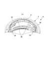
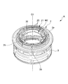
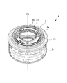
- FIG. 6A It is a perspective view seen from the image plane side which shows the main board (board part) of the lens barrel which concerns on one Embodiment. It is a perspective view which showed the main board (board part) of the lens barrel which concerns on one Embodiment, and was seen from the subject side. It is a perspective view which shows around the mount part of the lens barrel which concerns on one Embodiment. It is a figure which shows the circumference of the mount part of the lens barrel which concerns on one Embodiment, and is the perspective view which shows the state which the main board (board part) and the contact block (contact part) are assembled with FIG. 6A.
- the lens barrel is assumed to be the lens barrel of an imaging device such as a digital single-lens reflex camera, but the lens barrel is a single-lens reflex camera such as a digital video camera or a mirrorless camera. It is also applicable to the lens barrel of other imaging devices other than the above.
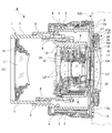
- the camera A which is the image pickup apparatus of the present embodiment, includes a camera body 100 and a lens barrel 1 that can be attached to and detached from the camera body 100.
- the camera body 100 contains, for example, an image sensor such as a CCD that captures a subject image via the lens barrel 1, an AF circuit for performing a focus operation, a camera CPU that controls the operation of the camera A, and various data. It is equipped with a microprocessor having a memory for storing.
- the lens barrel 1 of the present embodiment is provided on the image plane side / imaging side on the rear side in the axis O1 direction (optical axis O1 direction), and has a substantially annular mount portion 2 for connecting to the camera body 100 and a mount.
- a fixed cylinder 3 is coaxially provided by connecting and fixing the rear end portion to the portion 2, and the fixed cylinder 3 is coaxially arranged on the outer side in the radial direction and rotates at a predetermined angle (zoom rotation angle) around the axis O1.
- a zoom operation ring 4 provided as possible, a zoom ring interlocking ring 5 coaxially arranged inside the fixed cylinder 3 in the radial direction and rotating in conjunction with the zoom operation ring 4, and a radial direction of the zoom ring interlocking ring 5.
- a straight-moving cylinder 6 coaxially arranged on the inside and movable forward and backward in the axis O1 direction, and a first coaxially arranged on the inside in the radial direction of the straight cylinder 6 and movable forward and backward in the axis O1 direction.
- the moving cylinder 7 and the cam cylinder 8 coaxially arranged inside the first moving cylinder 7 in the radial direction and movable forward and backward in the axis O1 direction, and arranged coaxially inside the cam cylinder 8 in the radial direction.
- the second moving cylinder 9 is provided so as to be able to move forward and backward in the axis O1 direction
- the third movement is coaxially arranged inside the second moving cylinder 9 in the radial direction and is provided so as to be movable forward and backward in the axis O1 direction. It is provided with a cylinder 10.
- the lens barrel 1 of the present embodiment has four lenses, the first lens group L1, the second lens group L2, the third lens group L3, and the fourth lens group L4, in order from the subject side on the front side in the axis O1 direction. It has a group.
- the fixed cylinder 3 is formed by providing a straight groove extending along the axis O1 direction.
- the straight cylinder 6 is provided with a cam groove and a straight key on the inner diameter side.
- the cam cylinder 8 is provided with a first cam groove for moving the first lens group L1 forward and backward in the axis O1 direction on the outer diameter side, and the second lens group L2 and the third lens group L3 are provided on the inner diameter side, respectively.
- a second cam groove and a third cam groove for moving forward and backward in the axis O1 direction are provided.
- the cam cylinder 8 is provided with a follower that slides in contact with the cam groove of the straight cylinder 6.
- the first lens group L1 includes a lens and a first lens holding frame 15 for holding the lens, and has a first moving cylinder 7 provided with a follower engaged with a first cam groove of the cam cylinder 8. 1
- the lens holding frame 15 is screw-fixed and arranged.
- the second lens group L2 includes a lens and a second lens holding frame 16 for holding the lens, and has a third moving cylinder 10 provided with a follower engaged with a second cam groove of the cam cylinder 8. 2
- the lens holding frame 16 is fixed and arranged with screws.
- the third lens group L3 is a focus lens group, and includes a lens and a third lens holding frame 17 for holding the lens, and is provided by engaging a follower with a third cam groove of the cam cylinder 8.
- a third lens holding frame 17 is screw-fixed to the moving cylinder 9 and arranged.
- the fourth lens group L4 includes a lens and a fourth lens holding frame 18 for holding the lens, and the fourth lens holding frame 18 is screw-fixed to a mount portion 2 or the like.
- the second lens group L2 is provided with an aperture unit (aperture mechanism) 20 and a VR unit (camera shake correction mechanism) 21 controlled by a motor drive.
- the diaphragm unit 20 includes, for example, an annular press plate, an annular rotating member that rotates forward and reverse around the axis O1 by driving a stepping motor (aperture drive unit), and an opening that follows the rotation of the rotating member.
- the size, that is, the diaphragm is adjusted.
- nine diaphragm blades and an annular cam member are provided, and the diaphragm blades are interlocked with the drive of the diaphragm drive unit to adjust the size of the opening.
- a control device (CPU, control unit) 30 for controlling the drive of the aperture drive unit is arranged (mounted) on the main board M2 described later (FIG. 5A, etc.). Further, the main board M2 and the diaphragm drive unit are connected by a flexible board.
- the VR unit 21 reduces the image blur of the subject image caused by the vibration of the lens barrel 1 by shifting the VR lens of the second lens group L2 in the direction orthogonal to the optical axis.
- VR It includes a position detection sensor that detects the position of the lens and an actuator (VR drive unit) that displaces the VR lens according to the detection result of the position detection sensor.
- the VR drive unit includes, for example, a magnet and a coil, and is configured so that the VR lens can be shifted and moved in a direction perpendicular to the optical axis by controlling the energization of the coil.
- the control device (CPU, control unit) 30 for controlling the drive of the VR drive unit is arranged (mounted) on the main board M2 described later. Further, the main board M2 and the VR drive unit are connected by a flexible board.
- the third lens group L3 of the focus lens group includes a stepping motor (focus drive unit), a lead screw, a rack, etc., and is located in the optical axis direction of the lens barrel relative to the other lens groups.
- a focus drive mechanism 22 for driving forward and backward is provided.
- the control device (CPU, control unit) 30 for controlling the drive of the focus drive unit is arranged (mounted) on the main board M2 described later. Further, the main board M2 and the focus drive unit are connected by a flexible board.
- the control device for controlling the aperture drive unit, the control device for controlling the VR drive unit, and the control device for controlling the focus drive unit may be the same or may be provided separately.
- the first lens group L1, the second lens group L2, and the third lens group L3 move in the axis O1 direction along the first cam groove, the second cam groove, and the third cam groove, respectively. Move forward and backward. In this way, the first lens group L1, the second lens group L2, and the third lens group L3 move in the optical axis direction in the axis O1 direction, and the distance between the lens groups L1 to L4 fluctuates to zoom. ..
- the positions of the lens groups L1 to L4 and the in-line cylinder 6 by zooming are determined by the sum of the extension amount of the cam cylinder 8 and the extension amount of each lens group L1 to L4 with respect to the cam cylinder 8.
- the fourth lens group L4 is fixed.
- the lens barrel 1 is mechanically connected to the camera body 100 via the mount portion 2, and is provided as a contact terminal connected and supported by the mount portion 2.
- the (contact, contact portion) 25 (see FIGS. 5 and 6) and the contact terminal (contact, contact portion) of the camera body 100 are in contact with each other and are electrically connected, and power is supplied from the camera body 100.
- a communication unit is connected to the contact terminal 25, and information is transmitted and received between the lens barrel 1 and the camera body 100 via the contact terminal 25.
- the lens barrel 1 has a contact block having a plurality of contact terminals 25 and pins 26 for electrically and mechanically connecting the contact terminals 25 to the main substrate M2 described later.
- 27 is provided by positioning and fixing to the mount portion 2.
- the contact portion is composed of the contact terminal 25 and the pin 26 (contact block 27).
- a contact block receiver 31 that supports the contact block 27, a substrate receiver 32 that supports the main substrate M2, and an elastic member are arranged on the inner diameter side of the mount portion 2.
- the cushion base 33 is formed so as to project in the radial direction.
- the contact block 27 is arranged so as to be supported by the contact block receiver 31, and is screwed to the mount portion 2 by the contact block screw hole 34.
- the main board M2 is soldered to the contact block 27 as described later, and is arranged on the inner diameter side of the contact surface 2a described later as shown in FIG. 6B. Further, an elastic member (not shown) is arranged on the cushion base 33, and the main substrate M2 is arranged with the elastic member sandwiched between the elastic member and the cushion base 33 in the optical axis direction O1.
- the cushion base 33 is provided at three places.
- the main board M2 has a gap between it and the board receiver 32.
- the main substrate M2 is stably fixed by the substrate retainer 35. Specifically, the substrate retainer 35 is arranged so as to press the main substrate M2 from the image plane side to the subject side.
- the elastic member arranged on the cushion base 33 is crushed, and the main substrate M2 and the substrate receiver 32 come into contact with each other. As long as the main board M2 is stably held, there may be a gap between the main board M2 and the board receiver 32.
- the substrate retainer 35 is screwed to the mount portion 2 by the substrate retainer screw holes 36 in a state where the main substrate M2 is pressed in the optical axis direction O1.
- the main board M2 and the contact block 27 can be stably attached to the mount portion 2. Further, since the main substrate M2 is not fixed with screws or the like, it becomes thin in the optical axis direction. Further, since the main board M2 is attached by being sandwiched between the board holder 35 and the mount portion 2 (an elastic member placed on the cushion base 33), vibration such as a shutter shock is not easily transmitted to the main board M2, and the control unit 30 Noise is hard to get on.
- the fourth lens holding frame 18 is arranged on the inner diameter side of the substrate retainer 35, and is screwed to the substrate retainer 35 and the mount portion 2.
- the lens barrel 1 is connected to the contact terminal 25, and for example, power supply, zooming (in the case of power zoom, the zoom motor (zoom drive unit) is controlled), focusing, aperture adjustment, and camera shake.
- a main board (board part) M2 equipped with wiring and a control device (CPU or the like) 30 for performing operation control (control of various drive parts) such as correction is housed.
- the main board M2 may have one control device 30 or a plurality of control devices 30.
- the main substrate M2 is formed in a substantially annular plate shape, is arranged coaxially with the lens barrel 1, and has a mount portion 2. It is provided so as to be arranged on the inner diameter side of the contact surface (surface, mount surface) 2a that comes into contact with the camera body 100 of the above. Further, the main substrate M2 is arranged on the image plane side of the contact surface 2a of the mount portion 2 in the optical axis direction in the axis O1 direction. Further, the main substrate M2 is arranged between the fourth lens group L4 and the contact surface 2a in the radial direction centered on the optical axis.
- the main substrate M2 does not necessarily have to be formed in a substantially annular plate shape.
- the surface 2a is an annular surface, which is a reference surface that comes into contact with each other when the lens barrel 1 and the camera body 100 are mounted.
- the fixed cylinder 3 and the mount portion 2 are connected via the surface 2a. For example, when the fixing cylinder 3 and the mounting portion 2 are fixed with screws, a hole through which the screws penetrate is provided in the mounting portion 2a.
- the pin 26 of the contact block 27 is directly connected to the main board M2, and the pin 26 is soldered to the main board M2.
- the contact block 27 and thus the plurality of contact terminals 25 are connected to the main board M2 via the pins 26.
- the contact block 27 has a radius of curvature substantially equal to the radius of curvature of the main board M2 and is formed in a substantially arc shape, and the outer peripheral edge 27a of the contact block 27 is placed at the position of the outer peripheral edge m1 of the main board M2.
- the contact block 27 is mounted on the main board M2 so as to be substantially matched.
- the pin 26 and the main board M2 do not necessarily have to be directly connected, and may be connected via a flexible board.
- the lens barrel 1 of the present embodiment requires a shorter flexible substrate than the conventional one, and the arrangement area (occupied area) of the flexible substrate is small. It's done.
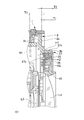
- the distance T1 in the axis O1 direction from one end 25a on the subject side of the contact terminal 25 to one end (one surface) m2 on the image plane side of the main substrate M2 is on the image plane side of the mount portion 2.
- the distance from one end 2b to the contact surface (surface, mount surface) 2a of the mount portion 2 is shorter than the distance T2. In other words, the distance from the contact terminal 25 to the main board M2 is smaller than the width of the mount portion 2.
- the main board M2 is arranged on the inner diameter side of the contact surface 2a of the mount portion 2 in contact with the camera body 100, and is arranged on the image plane side of the contact surface 2a of the mount portion 2.
- the main substrate M2 arranged in this way can be attached to and detached from the lens barrel 1 even when the plurality of cylinders 3 to 10 and the mount portion 2 constituting the lens barrel 1 are assembled. it can. That is, the main substrate M2 can be attached to and detached from the lens barrel 1 without disassembling the plurality of cylinders 3 to 10 and the mount portion 2.
- the components for example, the fixed cylinder 3, the zoom operation ring 4, and the like
- the zoom ring interlocking ring 5, the straight-ahead cylinder 6, the cam cylinder 8, each group moving cylinder 7, 9, 10, etc. move in the image plane direction, but from the main board M2 in order to avoid collision with the main board M2. It cannot move to the image plane side.
- each configuration is configured. Since the parts cannot be moved to the image plane side from the main board, the length of the product of the lens barrel 1 becomes longer than that when the main board is arranged at the position of M2. For example, the length of the lens barrel 1 becomes longer as T3 shown in FIG. 4A.
- the main substrate M2 is provided so as to be arranged on the inner diameter side of the contact surface 2a in contact with the camera body 100 of the mount portion 2. ing. Further, the main substrate M2 is arranged on the image plane side of the contact surface 2a of the mount portion 2 in the optical axis direction in the axis O1 direction.
- the lens barrel 1 is secured while securing the area required for extending each lens group L1 to L3 (L4) to the optimum position. It becomes possible to make the length of the lens smaller than before.
- the lens barrel 1 and the camera A of the present embodiment it is possible to further reduce the size, thickness, and weight as compared with the conventional case.
- the lens barrel 1 and the camera A of the present embodiment are configured by directly connecting the pin 26 (contact portion) to the main board M2, a flexible board connecting the pin 26 and the main board M2 becomes unnecessary. can do. As a result, it is not necessary to consider the arrangement / movable area (occupied area) of the flexible substrate, and the lens barrel 1 can be made smaller, thinner, and lighter. In addition, it is possible to reduce the cost by eliminating the need for a flexible substrate.
- the flexible board is shorter than the conventional one, and the arrangement area (occupied area) of the flexible board is small. Therefore, the lens barrel 1 is still used. Can be made smaller, thinner, and lighter.
- the contact block 27 is mounted on the main board M2 so that the outer peripheral edge 27a of the contact block 27 is substantially aligned with the position of the outer peripheral edge m1 of the main board M2.
- the contact block 27 and the main substrate M2 can be handled integrally, and the ease of handling and fitting of the lens barrel 1 for assembly and removal can be improved.
- the distance T1 in the axis O1 direction from one end 25b on the subject side of the contact terminal 25 to one end (one surface) m2 on the image plane side of the main substrate M2 is the mount portion 2.
- the distance from one end 2b on the image plane side to the contact surface (plane, mount surface) 2a of the mount portion 2 is shorter than the distance T2.
- one ends 8a and 9a on the image plane side of the cylinders are mounted on the mount portion 2 in the retracted state shown in FIG. It can be arranged on the image plane side in the optical axis O1 direction rather than one end 2c on the subject side. This makes it possible to further reduce the size, thickness, and weight.
- the main board M2 is arranged on the inner diameter side of the contact surface 2a of the mount portion 2 in contact with the camera body 100, and is arranged on the image plane side of the contact surface 2a of the mount portion 2. There is. As a result, the main substrate M2 can be individually attached to and detached from the state in which the plurality of cylinders 3 to 10 and the mount portion 2 constituting the lens barrel 1 are assembled.
- the main substrate M2 after assembling the various cylinders 3 to 10 and the mount portion 2, which facilitates the assembly of the lens barrel 1. Can be done. Further, when performing maintenance or parts replacement of the lens barrel 1, especially when replacing the main board M2, the main board M2 is removed without disassembling and removing the various cylinders 3 to 10 and the mount portion 2. Will be possible. This makes it possible to improve the efficiency of the manufacturing process and maintainability.
- the present invention is not limited to the above-mentioned one embodiment, and can be appropriately changed without departing from the spirit thereof, and any combination can be used. Good.
- a biaxial gyro sensor, an acceleration sensor, or the like is mounted on the main substrate M2 arranged on the rear side of the lens barrel 1 of the present embodiment in the optical axis O1 direction, camera shake can be prevented more accurately and accurately. It becomes possible to plan. That is, it is possible to realize more accurate and highly reliable detection performance and camera shake correction performance.
- the number and configuration of the lens group and the tubular body (ring body) do not need to be limited as in the present embodiment.
- Lens barrel 2 Mount 2a surface (contact surface, mount surface) 2b One end on the imaging surface side 2c One end on the subject side 3 Fixed cylinder 4 Zoom operation ring 5 Zoom ring interlocking ring 6 Straight cylinder 7 First moving cylinder (first moving ring) 8 Cam cylinder (cam ring) 9 Second moving cylinder (second moving ring) 10 Third moving cylinder (third moving ring) 20 Aperture unit (aperture mechanism) 21 VR unit (camera shake correction mechanism) 22 Focus drive mechanism 25 Contact terminals (contacts, contacts) 25a One end of the contact terminal on the subject side, pin 26 (contact part) 27 Contact block 27a Outer peripheral edge 27b One end on the subject side 30 Control device (control unit) 31 Contact block receiver 32 Board receiver 33 Cushion stand 34 Contact block screw hole 35 Board retainer 36 Board retainer screw hole 100 Camera body A Camera (imaging device) M1 Conventional main board M2 Main board (board part) m1 Outer peripheral edge m2 One end on the image plane side O1 Axis line, optical axis L1 1s
Landscapes
- Physics & Mathematics (AREA)
- General Physics & Mathematics (AREA)
- Optics & Photonics (AREA)
- Lens Barrels (AREA)
Abstract
さらなる小型化(薄型化)を可能にするレンズ鏡筒及び撮像装置を提供する。カメラボディ100と着脱可能なレンズ鏡筒1であって、カメラボディ100と接触する接触面2aを有するマウント部2と、マウント部2の接触面2aより内径側に配置される基板部M2とを備える。また、基板部M2を、光軸O1方向において、マウント部2の接触面2aより像面側に配置する。
Description
本発明は、レンズ鏡筒及びこれを備えた撮像装置に関する。
従来、一眼レフなどのレンズ鏡筒は、回路基板やレンズマウントが具備されている。また、レンズ鏡筒は、小型や薄型化が求められている。
本開示のレンズ鏡筒の一態様は、カメラボディに対して着脱可能なレンズ鏡筒であって、前記カメラボディと接触する接触面を有するマウント部と、前記カメラボディと情報の送受信を行う接点部と、前記接点部と接続し、前記マウント部の前記接触面より内周側に配置される基板部と、を備える構成とした。
本開示の撮像装置の一態様は、上記のレンズ鏡筒を備える構成とした。
以下、図1から図6を参照し、一実施形態に係るレンズ鏡筒及び撮像装置について説明する。
ここで、本実施形態では、レンズ鏡筒がデジタル一眼レフカメラなどの撮像装置のレンズ鏡筒であるものとして説明を行うが、レンズ鏡筒は、デジタルビデオカメラやミラーレスカメラなど、一眼レフカメラ以外の他の撮像装置のレンズ鏡筒に対しても適用可能である。
本実施形態の撮像装置であるカメラAは、図1から図3に示すように、カメラボディ100と、カメラボディ100に対して着脱可能なレンズ鏡筒1とを備えて構成されている。
カメラボディ100は、例えば、レンズ鏡筒1を介して被写体像を撮像するCCDなどの撮像素子と、フォーカス動作を行うためのAF回路と、カメラAの動作を制御するカメラCPU及び各種のデータを保存するメモリを有するマイクロプロセッサとを備えている。
本実施形態のレンズ鏡筒1は、軸線O1方向(光軸O1方向)後方側の像面側/撮像側に設けられ、カメラボディ100と接続するための略円環状のマウント部2と、マウント部2に後端部を接続固定して同軸上に設けられた固定筒3と、固定筒3の径方向外側に同軸上に配され、軸線O1周りに所定の角度(ズーム回転角)で回転可能に設けられたズーム操作環4と、固定筒3の径方向内側に同軸上に配され、ズーム操作環4に連動して回転するズームリング連動環5と、ズームリング連動環5の径方向内側に同軸上に配され、軸線O1方向に進退移動可能に設けられた直進筒6と、直進筒6の径方向内側に同軸上に配され、軸線O1方向に進退移動可能に設けられた第1移動筒7と、第1移動筒7の径方向内側に同軸上に配され、軸線O1方向に進退移動可能に設けられたカム筒8と、カム筒8の径方向内側に同軸上に配され、軸線O1方向に進退移動可能に設けられた第2移動筒9と、第2移動筒9の径方向内側に同軸上に配され、軸線O1方向に進退移動可能に設けられた第3移動筒10とを備えている。
また、本実施形態のレンズ鏡筒1は、軸線O1方向前方側の被写体側から順に、第1レンズ群L1、第2レンズ群L2、第3レンズ群L3、第4レンズ群L4の4つのレンズ群を備えている。
固定筒3は、軸線O1方向に沿って延びる直進溝を設けて形成されている。
直進筒6は、内径側に、カム溝と直進キーが設けられている。
直進筒6は、内径側に、カム溝と直進キーが設けられている。
カム筒8は、外径側に、第1レンズ群L1を軸線O1方向に進退移動させるための第1カム溝が設けられ、内径側に、第2レンズ群L2と第3レンズ群L3をそれぞれ軸線O1方向に進退移動させるための第2カム溝、第3カム溝が設けられている。カム筒8には、直進筒6のカム溝と接触摺動するフォロアが設けられている。
そして、カム筒8のフォロアが直進筒6の内径側のカム溝に係合してこのカム溝に沿って摺動し、直進筒6の直進キーが固定筒3の直進溝に係合して回転止め規制されている。
第1レンズ群L1は、レンズと、レンズを保持する第1レンズ保持枠15とを備え、フォロアをカム筒8の第1カム溝に係合して設けられた第1移動筒7に、第1レンズ保持枠15をねじ固定して配設されている。
第2レンズ群L2は、レンズと、レンズを保持する第2レンズ保持枠16とを備え、フォロアをカム筒8の第2カム溝に係合して設けられた第3移動筒10に、第2レンズ保持枠16をねじ固定して配設されている。
第3レンズ群L3は、フォーカスレンズ群であり、レンズと、レンズを保持する第3レンズ保持枠17とを備え、フォロアをカム筒8の第3カム溝に係合して設けられた第2移動筒9に、第3レンズ保持枠17をねじ固定して配設されている。
第4レンズ群L4は、レンズと、レンズを保持する第4レンズ保持枠18とを備え、第4レンズ保持枠18をマウント部2などにねじ固定して配設されている。
第2レンズ群L2には、モータ駆動で制御される絞りユニット(絞り機構)20、VRユニット(手ぶれ補正機構)21が設けられている。
絞りユニット20は、例えば、円環状のプレス板と、ステッピングモータ(絞り駆動部)の駆動によって軸線O1周りに正逆回転する円環状の回転部材と、回転部材の回転に従動して開口部の大きさ、すなわち絞りを調整する例えば9枚の複数の絞り羽根と、円環状のカム部材とを備え、絞り駆動部の駆動に絞り羽根を連動させて開口部の大きさを調整するように構成されている。また、本実施形態では、絞り駆動部の駆動を制御する制御装置(CPU、制御部)30が後述のメイン基板M2上に配置(実装)されている(図5A等)。さらに、メイン基板M2と絞り駆動部とがフレキシブル基板で接続されている。
VRユニット21は、第2レンズ群L2のVRレンズを光軸と直交する方向に変位させることによって、レンズ鏡筒1の振動に起因する被写体像の像ブレを低減するものであり、例えば、VRレンズの位置を検出する位置検出センサと、位置検出センサの検出結果に応じてVRレンズを変位させるアクチュエータ(VR駆動部)とを備えている。
VR駆動部は、例えば、マグネットとコイルとを備え、コイルへの通電を制御することでVRレンズを光軸と垂直な方向にシフト移動させることができるように構成されている。また、本実施形態では、VR駆動部の駆動を制御する制御装置(CPU、制御部)30が後述のメイン基板M2上に配置(実装)されている。さらに、メイン基板M2とVR駆動部とがフレキシブル基板で接続されている。
VR駆動部は、例えば、マグネットとコイルとを備え、コイルへの通電を制御することでVRレンズを光軸と垂直な方向にシフト移動させることができるように構成されている。また、本実施形態では、VR駆動部の駆動を制御する制御装置(CPU、制御部)30が後述のメイン基板M2上に配置(実装)されている。さらに、メイン基板M2とVR駆動部とがフレキシブル基板で接続されている。
また、フォーカスレンズ群の第3レンズ群L3には、ステッピングモータ(フォーカス駆動部)、リードスクリュー、ラックなどからなり、他のレンズ群に対し相対的にレンズ鏡筒の軸線方向の光軸方向に進退駆動させるためのフォーカス駆動機構22が設けられている。また、本実施形態では、フォーカス駆動部の駆動を制御する制御装置(CPU、制御部)30が後述のメイン基板M2上に配置(実装)されている。さらに、メイン基板M2とフォーカス駆動部とがフレキシブル基板で接続されている。
なお、絞り駆動部を制御する制御装置とVR駆動部を制御する制御装置とフォーカス駆動部を制御する制御装置は、同一であってもよいし、それぞれ別で備えられていてもよい。
なお、絞り駆動部を制御する制御装置とVR駆動部を制御する制御装置とフォーカス駆動部を制御する制御装置は、同一であってもよいし、それぞれ別で備えられていてもよい。
そして、上記構成からなる本実施形態のレンズ鏡筒1においては、ズーム操作環4を軸線O1周りに正逆回転させると、カム筒8が同量軸線O1周りに正逆回転し、カム筒8が正逆回転するとともに直進筒6が軸線O1方向に進退移動する。
カム筒8が正逆回転するとともに、第1レンズ群L1、第2レンズ群L2、第3レンズ群L3が、第1カム溝、第2カム溝、第3カム溝に沿ってそれぞれ軸線O1方向に進退移動する。このように、第1レンズ群L1、第2レンズ群L2、第3レンズ群L3が軸線O1方向の光軸方向に移動し、レンズ群L1~L4の相互の距離が変動することによってズーミングされる。
なお、ズーミングによる各レンズ群L1~L4と直進筒6の位置は、カム筒8の繰り出し量と、カム筒8に対する各レンズ群L1~L4の繰り出し量の和によって決まる。本実施形態において、第4レンズ群L4は固定している。
一方、レンズ鏡筒1は、図1から図3等に示すように、カメラボディ100にマウント部2を介して機械的に接続されるとともに、マウント部2に接続支持して設けられた接触端子(接点、接点部)25(図5、6参照)とカメラボディ100の接触端子(接点、接点部)が接触して電気的に接続され、カメラボディ100から電力が供給される。また、接触端子25には通信ユニットが接続され、接触端子25を介してレンズ鏡筒1とカメラボディ100の間で情報の送受信を行うように構成されている。
レンズ鏡筒1には、図5、6に示すように、複数の接触端子25と、接触端子25を後述のメイン基板M2に電気的及び機械的に接続するためのピン26とを有する接点ブロック27がマウント部2に位置決め固定して具備されている。なお、本実施形態では、接触端子25とピン26(接点ブロック27)によって接点部が構成されている。
具体的には、図6Aに示すように、マウント部2の内径側には、接点ブロック27を支持する接点ブロック受け31と、メイン基板M2を支持する基板受け32と、弾性部材が配置されるクッション台33と、が径方向に突出して形成されている。接点ブロック27は、接点ブロック受け31に支持されるように配置され、接点ブロック用ビス穴34によってマウント部2にビス止めされる。
また、メイン基板M2は、後述するように接点ブロック27と半田付けされており、図6Bに示すように後述する接触面2aよりも内径側に配置される。さらに、クッション台33には弾性部材(図示せず)が配置されており、メイン基板M2は光軸方向O1において弾性部材をクッション台33との間に挟んで配置されている。クッション台33は3箇所設けられている。メイン基板M2は、図6Bの状態では、基板受け32との間には隙間を有している。メイン基板M2は、図6Cに示すように、基板押え35によって安定して固定される。具体的には、基板押え35は像面側から被写体側へメイン基板M2を押し付けるように配置される。このときクッション台33に配置された弾性部材が押しつぶされ、メイン基板M2と基板受け32とが当接する。なお、メイン基板M2が安定して保持されていれば、メイン基板M2と基板受け32との間に隙間があってもよい。基板押え35は、メイン基板M2を光軸方向O1に押し付けた状態で、基板押え用ビス穴36によってマウント部2にビス止めされる。
上記構成によって、マウント部2に対して、メイン基板M2及び接点ブロック27を安定して取り付けることができる。また、メイン基板M2はビス等で固定されていないため光軸方向に薄型となる。さらに、メイン基板M2は基板押え35とマウント部2(クッション台33に置かれた弾性部材)とに挟んで取り付けられているので、シャッターショック等の振動がメイン基板M2に伝わりにくく、制御部30にノイズがのりにくい。
また、図6Dに示すように、第4レンズ保持枠18は、基板押え35の内径側に配置され、基板押え35及びマウント部2にビス止めされる。
また図5に示すように、レンズ鏡筒1には、接触端子25と接続し、例えば、給電、ズーミング(パワーズームの場合、ズームモータ(ズーム駆動部)を制御)、フォーカシング、絞り調整、手ぶれ補正などの動作制御(各種駆動部の制御)などを行うための配線、制御装置(CPUなど)30を実装して備えたメイン基板(基板部)M2が収容されている。なお、メイン基板M2の制御装置30は1つでも良いし、複数あってもよい。
本実施形態のレンズ鏡筒1においては図1~図3等に示すように、メイン基板M2が、略円環板状に形成され、レンズ鏡筒1と同軸上に配され、且つマウント部2のカメラボディ100と接触する接触面(面、マウント面)2aよりも内径側に配置して設けられている。さらに、メイン基板M2は、軸線O1方向の光軸方向において、マウント部2の接触面2aより像面側に配置されている。また、メイン基板M2は、光軸を中心とする径方向において、第4レンズ群L4と接触面2aとの間に配置されている。なお、メイン基板M2は必ずしも略円環板状に形成されていなくてもよい。
また、面2aは円環状の面であり、レンズ鏡筒1とカメラボディ100とが装着されている場合に互いに接触する基準面である。固定筒3とマウント部2とは、面2aを介して接続される。例えば、固定筒3とマウント部2とがネジで固定される場合は、マウント部2aにネジが貫通する穴が設けられる。
また、面2aは円環状の面であり、レンズ鏡筒1とカメラボディ100とが装着されている場合に互いに接触する基準面である。固定筒3とマウント部2とは、面2aを介して接続される。例えば、固定筒3とマウント部2とがネジで固定される場合は、マウント部2aにネジが貫通する穴が設けられる。
また、図5に示すように接点ブロック27のピン26をメイン基板M2に直接接続し、メイン基板M2にピン26が半田付けされる。これによって、接点ブロック27ひいては複数の接触端子25がピン26を介してメイン基板M2に接続される。
このとき、例えば、接点ブロック27がメイン基板M2の曲率半径と略同等の曲率半径を有して略円弧状に形成され、メイン基板M2の外周縁m1の位置に接点ブロック27の外周縁27aを略一致させるなどして、メイン基板M2に接点ブロック27が実装されている。
これにより、本実施形態では、ピン26とメイン基板M2を接続するフレキシブル基板が不要となる。
なお、必ずしもピン26とメイン基板M2を直接接続しなくてもよく、フレキシブル基板を介して接続してもよい。本実施形態のレンズ鏡筒1は、このようにフレキシブル基板を用いてピン26とメイン基板M2を接続する場合に、従来よりも短いフレキシブル基板で済み、フレキシブル基板の配置領域(占有領域)が小さくて済む。
さらに、図4Bに示すように、接触端子25の被写体側の一端25aからメイン基板M2の像面側の一端(一面)m2までの軸線O1方向の距離T1は、マウント部2の像面側の一端2bからマウント部2の接触面(面、マウント面)2aまでの距離T2より短くなっている。言い換えると、接触端子25からメイン基板M2までの距離は、マウント部2の幅よりも小さい。
本実施形態では、メイン基板M2がマウント部2のカメラボディ100と接触する接触面2aよりも内径側に配置し、マウント部2の接触面2aより像面側に配置して設けられている。このように配置されたメイン基板M2は、レンズ鏡筒1を構成する上記の複数の筒3~10やマウント部2を組み付けた状態であっても、レンズ鏡筒1に対して着脱することができる。すなわち、複数の筒3~10やマウント部2を分解することなく、メイン基板M2はレンズ鏡筒1に対して着脱可能とされている。
ここで、撮影状態から沈胴状態へした場合、レンズ群L1~L3(L4)を光軸方向の軸線O1方向に進退駆動させるために必要な構成部品(例えば、固定筒3、ズーム操作環4、ズームリング連動環5、直進筒6、カム筒8、各群移動筒7、9、10など)は、像面方向へ移動するが、メイン基板M2との衝突を回避するためにメイン基板M2より像面側へは移動できない。
よって、メイン基板M2がマウント部2より被写体側にある場合や、マウント部2より内径側にない場合(例えば図1、図4AのM1で示す位置にメイン基板がある場合)には、各構成部品がメイン基板より像面側に移動できないため、メイン基板がM2の位置に配置されている場合と比べてレンズ鏡筒1の製品の長さが長くなってしまう。例えば、図4Aに示すT3程、レンズ鏡筒1の長さが長くなってしまう。
これに対し、本実施形態のレンズ鏡筒1及びカメラ(撮像装置)Aにおいては、メイン基板M2が、マウント部2のカメラボディ100と接触する接触面2aよりも内径側に配置して設けられている。さらに、メイン基板M2は、軸線O1方向の光軸方向において、マウント部2の接触面2aより像面側に配置されている。
このようにメイン基板M2が配置されていることにより、図1に示すように、各レンズ群L1~L3(L4)を最適な位置まで繰り出すために必要な領域を確保しつつ、レンズ鏡筒1の長さを従来より小さくすることが可能になる。
したがって、本実施形態のレンズ鏡筒1及びカメラAによれば、従来と比較し、さらなる小型化、薄型化、軽量化を図ることが可能になる。
本実施形態のレンズ鏡筒1及びカメラAにおいては、ピン26(接点部)をメイン基板M2に直接接続して構成されていることにより、ピン26とメイン基板M2を接続するフレキシブル基板を不要にすることができる。これにより、フレキシブル基板の配置/可動領域(占有領域)を考慮する必要がなく、レンズ鏡筒1をより小型化、薄型化、軽量化することが可能になる。また、フレキシブル基板を不要にすることで低コスト化を図ることも可能になる。
フレキシブル基板を用いてピン26とメイン基板M2を接続した場合であっても、従来よりも短いフレキシブル基板で済み、フレキシブル基板の配置領域(占有領域)が小さくて済むため、やはり、レンズ鏡筒1をより小型化、薄型化、軽量化することが可能になる。
本実施形態のレンズ鏡筒1及びカメラAにおいては、メイン基板M2の外周縁m1の位置に接点ブロック27の外周縁27aを略一致させて、メイン基板M2に接点ブロック27が実装されている。これにより、接点ブロック27とメイン基板M2を一体にして取り扱うことができ、レンズ鏡筒1への組み付け、取り外しの取扱性や納まりをよくすることができる。
本実施形態のレンズ鏡筒1及びカメラAにおいては、接触端子25の被写体側の一端25bからメイン基板M2の像面側の一端(一面)m2までの軸線O1方向の距離T1が、マウント部2の像面側の一端2bからマウント部2の接触面(面、マウント面)2aまでの距離T2より短くなっている。
これにより、メイン基板M2及び接点ブロック27の納まりを良くすることができ、レンズ鏡筒1をより小型化、薄型化、軽量化することが可能になる。
これにより、メイン基板M2及び接点ブロック27の納まりを良くすることができ、レンズ鏡筒1をより小型化、薄型化、軽量化することが可能になる。
また、本実施形態のようなメイン基板M2の配置位置によって、図1に示す沈胴状態において、筒(カム筒8、第2移動筒9)の像面側の一端8a、9aがマウント部2の被写体側の一端2cよりも光軸O1方向において像面側に配置することができる。
これにより、さらに小型化、薄型化、軽量化を図ることが可能になる。
これにより、さらに小型化、薄型化、軽量化を図ることが可能になる。
また、本実施形態では、メイン基板M2がマウント部2のカメラボディ100と接触する接触面2aよりも内径側に配置し、マウント部2の接触面2aより像面側に配置して設けられている。これにより、レンズ鏡筒1を構成する上記の複数の筒3~10やマウント部2を組み付けた状態で、メイン基板M2を個別に着脱することも可能になる。
よって、レンズ鏡筒1の製造時等において、各種筒3~10やマウント部2を組み付けた後、メイン基板M2を最後に組み込むことが可能になり、レンズ鏡筒1の組み立てを容易にすることができる。また、レンズ鏡筒1のメンテナンス、部品交換などを行う際に、特にメイン基板M2を交換する場合などにおいて、各種筒3~10やマウント部2を分解、取り外しすることなく、メイン基板M2を取り外すことが可能になる。これにより、製造工程の効率化、メンテナンス性の向上等を図ることが可能になる。
以上、レンズ鏡筒及び撮像装置の一実施形態について説明したが、本発明は上記の一実施形態に限定されるものではなく、その趣旨を逸脱しない範囲で適宜変更可能であり、任意の組み合わせでもよい。
例えば、本実施形態のレンズ鏡筒1の光軸O1方向後方側に配設されるメイン基板M2に、二軸ジャイロセンサ、加速度センサなどを実装するようにすれば、より正確で精度よく手ぶれ防止を図ることが可能になる。すなわち、より高精度で信頼性の高い検知性能、手ぶれ補正性能を実現することができる。
また、レンズ群や筒体(環体)の数、構成は本実施形態のように限定する必要はない。
1 レンズ鏡筒
2 マウント部
2a 面(接触面、マウント面)
2b 撮像面側の一端
2c 被写体側の一端
3 固定筒
4 ズーム操作環
5 ズームリング連動環
6 直進筒
7 第1移動筒(第1移動環)
8 カム筒(カム環)
9 第2移動筒(第2移動環)
10 第3移動筒(第3移動環)
20 絞りユニット(絞り機構)
21 VRユニット(手ぶれ補正機構)
22 フォーカス駆動機構
25 接触端子(接点、接点部)
25a 接触端子の被写体側の一端
26 ピン(接点部)
27 接点ブロック
27a 外周縁
27b 被写体側の一端
30 制御装置(制御部)
31 接点ブロック受け
32 基板受け
33 クッション台
34 接点ブロック用ビス穴
35 基板押え
36 基板押え用ビス穴
100 カメラボディ
A カメラ(撮像装置)
M1 従来のメイン基板
M2 メイン基板(基板部)
m1 外周縁
m2 像面側の一端
O1 軸線、光軸
L1 第1レンズ群
L2 第2レンズ群
L3 第3レンズ群
L4 第4レンズ群
Claims (14)
- カメラボディに対して着脱可能なレンズ鏡筒であって、
前記カメラボディと接触する接触面を有するマウント部と、
前記カメラボディと情報の送受信を行う接点部と、
前記接点部と接続し、前記マウント部の前記接触面より内周側に配置される基板部と、を備えるレンズ鏡筒。 - 前記基板部は、光軸方向において、前記マウント部の前記接触面より像面側に配置される、請求項1に記載のレンズ鏡筒。
- 前記接点部と前記基板部とは直接的に接続されている、請求項1または請求項2に記載のレンズ鏡筒。
- 前記接点部の被写体側の一端から前記基板部の像面側の一端までの距離は、前記マウント部の像面側の一端から前記マウント部の前記接触面までの距離より短い、請求項3に記載のレンズ鏡筒。
- 光軸方向において、前記接点部と前記基板部との間には、フレキシブル基板が配置されない、請求項3又は請求項4に記載のレンズ鏡筒。
- 複数のレンズを備え、
前記基板部は、光軸を中心とする径方向において、前記複数のレンズのうち少なくとも1つと前記接触面との間に配置される
請求項1から請求項5の何れか1項に記載のレンズ鏡筒。 - 光軸方向又は光軸と交差する方向に移動可能なレンズと、
前記レンズを駆動する駆動部と、
前記基板部上に配置され、前記駆動部を制御する制御部と、を備える、請求項1から請求項5の何れか1項に記載のレンズ鏡筒。 - 絞り機構と、
前記絞りを駆動する駆動部と、
前記基板上に配置され、前記駆動部を制御する制御部と、を備える、請求項1から請求項6の何れか1項に記載のレンズ鏡筒。 - 前記基板部と前記駆動部とを接続するフレキシブル基板を備える、請求項6又は請求項7に記載のレンズ鏡筒。
- レンズを保持する複数の筒を備え、
前記基板部は、前記複数の筒を分解せずに取り外し可能である、請求項1から請求項8のいずれか1項に記載のレンズ鏡筒。 - レンズを保持する複数の筒を備え、
前記複数の筒と前記マウント部とが組み立てられた後に、前記基板部を取り付け可能である、請求項1から請求項9の何れか1項に記載のレンズ鏡筒。 - 前記接触面は、円環状である
請求項1から請求項11の何れか1項に記載のレンズ鏡筒。 - 光軸方向に移動可能な筒を備え、
沈胴状態において、前記筒の像面側の一端は、前記マウント部の被写体側の一端よりも光軸方向において像面側に配置される
請求項1から請求項9の何れか1項に記載のレンズ鏡筒。 - 請求項1から請求項13の何れか1項に記載のレンズ鏡筒を備える撮像装置。
Priority Applications (1)
| Application Number | Priority Date | Filing Date | Title |
|---|---|---|---|
| JP2021515916A JPWO2020217870A1 (ja) | 2019-04-22 | 2020-03-30 |
Applications Claiming Priority (2)
| Application Number | Priority Date | Filing Date | Title |
|---|---|---|---|
| JP2019-081112 | 2019-04-22 | ||
| JP2019081112 | 2019-04-22 |
Publications (1)
| Publication Number | Publication Date |
|---|---|
| WO2020217870A1 true WO2020217870A1 (ja) | 2020-10-29 |
Family
ID=72942528
Family Applications (1)
| Application Number | Title | Priority Date | Filing Date |
|---|---|---|---|
| PCT/JP2020/014586 Ceased WO2020217870A1 (ja) | 2019-04-22 | 2020-03-30 | レンズ鏡筒及び撮像装置 |
Country Status (2)
| Country | Link |
|---|---|
| JP (1) | JPWO2020217870A1 (ja) |
| WO (1) | WO2020217870A1 (ja) |
Cited By (1)
| Publication number | Priority date | Publication date | Assignee | Title |
|---|---|---|---|---|
| CN113114918A (zh) * | 2021-04-30 | 2021-07-13 | 维沃移动通信有限公司 | 一种摄像头及电子设备 |
Citations (2)
| Publication number | Priority date | Publication date | Assignee | Title |
|---|---|---|---|---|
| JP2006267697A (ja) * | 2005-03-24 | 2006-10-05 | Fuji Photo Film Co Ltd | デジタルカメラ及びレンズユニット |
| WO2014115760A1 (ja) * | 2013-01-25 | 2014-07-31 | オリンパスイメージング株式会社 | レンズ鏡筒 |
Family Cites Families (9)
| Publication number | Priority date | Publication date | Assignee | Title |
|---|---|---|---|---|
| JP2001116972A (ja) * | 1999-10-19 | 2001-04-27 | Canon Inc | 交換レンズ鏡筒の電気配線装置 |
| JP2007288359A (ja) * | 2006-04-13 | 2007-11-01 | Fujifilm Corp | デジタルカメラ |
| JP2008046332A (ja) * | 2006-08-15 | 2008-02-28 | Fujifilm Corp | レンズユニット及びデジタルカメラ |
| JP2010164872A (ja) * | 2009-01-19 | 2010-07-29 | Sigma Corp | 交換レンズ |
| JP2011145322A (ja) * | 2010-01-12 | 2011-07-28 | Panasonic Corp | 交換レンズユニットおよびデジタルカメラ |
| US8502900B2 (en) * | 2010-01-14 | 2013-08-06 | Panasonic Corporation | Digital camera and interchangeable lens unit |
| WO2012107965A1 (ja) * | 2011-02-09 | 2012-08-16 | パナソニック株式会社 | レンズ鏡筒および撮像装置 |
| JP6084524B2 (ja) * | 2013-06-25 | 2017-02-22 | 株式会社シグマ | 交換レンズ |
| JP6485026B2 (ja) * | 2014-12-16 | 2019-03-20 | コニカミノルタ株式会社 | レンズ鏡胴 |
-
2020
- 2020-03-30 WO PCT/JP2020/014586 patent/WO2020217870A1/ja not_active Ceased
- 2020-03-30 JP JP2021515916A patent/JPWO2020217870A1/ja active Pending
Patent Citations (2)
| Publication number | Priority date | Publication date | Assignee | Title |
|---|---|---|---|---|
| JP2006267697A (ja) * | 2005-03-24 | 2006-10-05 | Fuji Photo Film Co Ltd | デジタルカメラ及びレンズユニット |
| WO2014115760A1 (ja) * | 2013-01-25 | 2014-07-31 | オリンパスイメージング株式会社 | レンズ鏡筒 |
Cited By (2)
| Publication number | Priority date | Publication date | Assignee | Title |
|---|---|---|---|---|
| CN113114918A (zh) * | 2021-04-30 | 2021-07-13 | 维沃移动通信有限公司 | 一种摄像头及电子设备 |
| CN113114918B (zh) * | 2021-04-30 | 2022-12-23 | 维沃移动通信有限公司 | 一种摄像头及电子设备 |
Also Published As
| Publication number | Publication date |
|---|---|
| JPWO2020217870A1 (ja) | 2020-10-29 |
Similar Documents
| Publication | Publication Date | Title |
|---|---|---|
| JP7157314B2 (ja) | カメラモジュール、及びカメラ搭載装置 | |
| US7414802B2 (en) | Lens apparatus and camera | |
| JP4764075B2 (ja) | 像ぶれ補正装置、該像ぶれ補正装置を備えたレンズ鏡筒 | |
| CN103748492A (zh) | 透镜镜筒 | |
| JP2021103271A (ja) | 手振れ補正機能付き撮像装置 | |
| JP4750402B2 (ja) | 光学機器 | |
| WO2019064946A1 (ja) | レンズ鏡筒及び撮像装置 | |
| US9936136B2 (en) | Lens barrel | |
| US11487075B2 (en) | Lens apparatus and imaging apparatus | |
| JP2016109750A (ja) | レンズ鏡胴及び撮像装置 | |
| JP2025047841A (ja) | 光学機器 | |
| JP7566644B2 (ja) | レンズ装置、撮像装置、及び撮像システム | |
| JP6448186B2 (ja) | レンズ鏡筒およびこれを備えた光学機器 | |
| JP2008107533A (ja) | レンズ鏡筒の調整構造 | |
| US10025059B2 (en) | Optical apparatus | |
| JP7616318B2 (ja) | レンズ鏡筒及び撮像装置 | |
| JP2015203751A (ja) | レンズ鏡筒および撮像装置 | |
| JP2019159081A (ja) | レンズ装置およびそれを備えた撮像装置 | |
| JP7721361B2 (ja) | 光学機器、レンズ鏡筒及び撮像装置 | |
| JP2007241103A (ja) | 撮像装置およびレンズ装置 | |
| JP2020034854A (ja) | レンズ装置、及び、カメラシステム | |
| JP2002196206A (ja) | レンズ鏡筒およびカメラ | |
| JP4731854B2 (ja) | 光学機器 | |
| JP2025047840A (ja) | 光学機器 | |
| JP2016130763A (ja) | レンズ鏡筒、光学機器、および、撮像装置 |
Legal Events
| Date | Code | Title | Description |
|---|---|---|---|
| 121 | Ep: the epo has been informed by wipo that ep was designated in this application |
Ref document number: 20794726 Country of ref document: EP Kind code of ref document: A1 |
|
| ENP | Entry into the national phase |
Ref document number: 2021515916 Country of ref document: JP Kind code of ref document: A |
|
| NENP | Non-entry into the national phase |
Ref country code: DE |
|
| 122 | Ep: pct application non-entry in european phase |
Ref document number: 20794726 Country of ref document: EP Kind code of ref document: A1 |