WO2020217756A1 - 液滴吐出装置および液滴吐出方法 - Google Patents
液滴吐出装置および液滴吐出方法 Download PDFInfo
- Publication number
- WO2020217756A1 WO2020217756A1 PCT/JP2020/010369 JP2020010369W WO2020217756A1 WO 2020217756 A1 WO2020217756 A1 WO 2020217756A1 JP 2020010369 W JP2020010369 W JP 2020010369W WO 2020217756 A1 WO2020217756 A1 WO 2020217756A1
- Authority
- WO
- WIPO (PCT)
- Prior art keywords
- droplet
- liquid
- droplet ejection
- tip
- ejection
- Prior art date
Links
Images


Classifications
-
- B—PERFORMING OPERATIONS; TRANSPORTING
- B05—SPRAYING OR ATOMISING IN GENERAL; APPLYING FLUENT MATERIALS TO SURFACES, IN GENERAL
- B05D—PROCESSES FOR APPLYING FLUENT MATERIALS TO SURFACES, IN GENERAL
- B05D1/00—Processes for applying liquids or other fluent materials
- B05D1/26—Processes for applying liquids or other fluent materials performed by applying the liquid or other fluent material from an outlet device in contact with, or almost in contact with, the surface
-
- B—PERFORMING OPERATIONS; TRANSPORTING
- B05—SPRAYING OR ATOMISING IN GENERAL; APPLYING FLUENT MATERIALS TO SURFACES, IN GENERAL
- B05B—SPRAYING APPARATUS; ATOMISING APPARATUS; NOZZLES
- B05B1/00—Nozzles, spray heads or other outlets, with or without auxiliary devices such as valves, heating means
- B05B1/02—Nozzles, spray heads or other outlets, with or without auxiliary devices such as valves, heating means designed to produce a jet, spray, or other discharge of particular shape or nature, e.g. in single drops, or having an outlet of particular shape
- B05B1/08—Nozzles, spray heads or other outlets, with or without auxiliary devices such as valves, heating means designed to produce a jet, spray, or other discharge of particular shape or nature, e.g. in single drops, or having an outlet of particular shape of pulsating nature, e.g. delivering liquid in successive separate quantities
- B05B1/083—Nozzles, spray heads or other outlets, with or without auxiliary devices such as valves, heating means designed to produce a jet, spray, or other discharge of particular shape or nature, e.g. in single drops, or having an outlet of particular shape of pulsating nature, e.g. delivering liquid in successive separate quantities the pulsating mechanism comprising movable parts
-
- B—PERFORMING OPERATIONS; TRANSPORTING
- B05—SPRAYING OR ATOMISING IN GENERAL; APPLYING FLUENT MATERIALS TO SURFACES, IN GENERAL
- B05B—SPRAYING APPARATUS; ATOMISING APPARATUS; NOZZLES
- B05B12/00—Arrangements for controlling delivery; Arrangements for controlling the spray area
- B05B12/14—Arrangements for controlling delivery; Arrangements for controlling the spray area for supplying a selected one of a plurality of liquids or other fluent materials or several in selected proportions to a spray apparatus, e.g. to a single spray outlet
- B05B12/1472—Arrangements for controlling delivery; Arrangements for controlling the spray area for supplying a selected one of a plurality of liquids or other fluent materials or several in selected proportions to a spray apparatus, e.g. to a single spray outlet separate supply lines supplying different materials to separate outlets of the spraying apparatus
-
- B—PERFORMING OPERATIONS; TRANSPORTING
- B05—SPRAYING OR ATOMISING IN GENERAL; APPLYING FLUENT MATERIALS TO SURFACES, IN GENERAL
- B05B—SPRAYING APPARATUS; ATOMISING APPARATUS; NOZZLES
- B05B5/00—Electrostatic spraying apparatus; Spraying apparatus with means for charging the spray electrically; Apparatus for spraying liquids or other fluent materials by other electric means
- B05B5/025—Discharge apparatus, e.g. electrostatic spray guns
- B05B5/0255—Discharge apparatus, e.g. electrostatic spray guns spraying and depositing by electrostatic forces only
-
- B—PERFORMING OPERATIONS; TRANSPORTING
- B05—SPRAYING OR ATOMISING IN GENERAL; APPLYING FLUENT MATERIALS TO SURFACES, IN GENERAL
- B05C—APPARATUS FOR APPLYING FLUENT MATERIALS TO SURFACES, IN GENERAL
- B05C5/00—Apparatus in which liquid or other fluent material is projected, poured or allowed to flow on to the surface of the work
-
- B—PERFORMING OPERATIONS; TRANSPORTING
- B05—SPRAYING OR ATOMISING IN GENERAL; APPLYING FLUENT MATERIALS TO SURFACES, IN GENERAL
- B05C—APPARATUS FOR APPLYING FLUENT MATERIALS TO SURFACES, IN GENERAL
- B05C9/00—Apparatus or plant for applying liquid or other fluent material to surfaces by means not covered by any preceding group, or in which the means of applying the liquid or other fluent material is not important
- B05C9/06—Apparatus or plant for applying liquid or other fluent material to surfaces by means not covered by any preceding group, or in which the means of applying the liquid or other fluent material is not important for applying two different liquids or other fluent materials, or the same liquid or other fluent material twice, to the same side of the work
-
- B—PERFORMING OPERATIONS; TRANSPORTING
- B05—SPRAYING OR ATOMISING IN GENERAL; APPLYING FLUENT MATERIALS TO SURFACES, IN GENERAL
- B05D—PROCESSES FOR APPLYING FLUENT MATERIALS TO SURFACES, IN GENERAL
- B05D1/00—Processes for applying liquids or other fluent materials
- B05D1/36—Successively applying liquids or other fluent materials, e.g. without intermediate treatment
-
- B—PERFORMING OPERATIONS; TRANSPORTING
- B41—PRINTING; LINING MACHINES; TYPEWRITERS; STAMPS
- B41J—TYPEWRITERS; SELECTIVE PRINTING MECHANISMS, i.e. MECHANISMS PRINTING OTHERWISE THAN FROM A FORME; CORRECTION OF TYPOGRAPHICAL ERRORS
- B41J2/00—Typewriters or selective printing mechanisms characterised by the printing or marking process for which they are designed
- B41J2/005—Typewriters or selective printing mechanisms characterised by the printing or marking process for which they are designed characterised by bringing liquid or particles selectively into contact with a printing material
- B41J2/01—Ink jet
- B41J2/015—Ink jet characterised by the jet generation process
- B41J2/04—Ink jet characterised by the jet generation process generating single droplets or particles on demand
- B41J2/045—Ink jet characterised by the jet generation process generating single droplets or particles on demand by pressure, e.g. electromechanical transducers
- B41J2/04501—Control methods or devices therefor, e.g. driver circuits, control circuits
- B41J2/04576—Control methods or devices therefor, e.g. driver circuits, control circuits controlling heads of electrostatic type
-
- B—PERFORMING OPERATIONS; TRANSPORTING
- B41—PRINTING; LINING MACHINES; TYPEWRITERS; STAMPS
- B41J—TYPEWRITERS; SELECTIVE PRINTING MECHANISMS, i.e. MECHANISMS PRINTING OTHERWISE THAN FROM A FORME; CORRECTION OF TYPOGRAPHICAL ERRORS
- B41J2/00—Typewriters or selective printing mechanisms characterised by the printing or marking process for which they are designed
- B41J2/005—Typewriters or selective printing mechanisms characterised by the printing or marking process for which they are designed characterised by bringing liquid or particles selectively into contact with a printing material
- B41J2/01—Ink jet
- B41J2/015—Ink jet characterised by the jet generation process
- B41J2/04—Ink jet characterised by the jet generation process generating single droplets or particles on demand
- B41J2/045—Ink jet characterised by the jet generation process generating single droplets or particles on demand by pressure, e.g. electromechanical transducers
- B41J2/04501—Control methods or devices therefor, e.g. driver circuits, control circuits
- B41J2/04581—Control methods or devices therefor, e.g. driver circuits, control circuits controlling heads based on piezoelectric elements
-
- B—PERFORMING OPERATIONS; TRANSPORTING
- B41—PRINTING; LINING MACHINES; TYPEWRITERS; STAMPS
- B41J—TYPEWRITERS; SELECTIVE PRINTING MECHANISMS, i.e. MECHANISMS PRINTING OTHERWISE THAN FROM A FORME; CORRECTION OF TYPOGRAPHICAL ERRORS
- B41J2/00—Typewriters or selective printing mechanisms characterised by the printing or marking process for which they are designed
- B41J2/005—Typewriters or selective printing mechanisms characterised by the printing or marking process for which they are designed characterised by bringing liquid or particles selectively into contact with a printing material
- B41J2/01—Ink jet
- B41J2/135—Nozzles
- B41J2/14—Structure thereof only for on-demand ink jet heads
- B41J2/14201—Structure of print heads with piezoelectric elements
-
- B—PERFORMING OPERATIONS; TRANSPORTING
- B41—PRINTING; LINING MACHINES; TYPEWRITERS; STAMPS
- B41J—TYPEWRITERS; SELECTIVE PRINTING MECHANISMS, i.e. MECHANISMS PRINTING OTHERWISE THAN FROM A FORME; CORRECTION OF TYPOGRAPHICAL ERRORS
- B41J2/00—Typewriters or selective printing mechanisms characterised by the printing or marking process for which they are designed
- B41J2/005—Typewriters or selective printing mechanisms characterised by the printing or marking process for which they are designed characterised by bringing liquid or particles selectively into contact with a printing material
- B41J2/01—Ink jet
- B41J2/135—Nozzles
- B41J2/14—Structure thereof only for on-demand ink jet heads
- B41J2/14314—Structure of ink jet print heads with electrostatically actuated membrane
Definitions
- the present invention relates to a droplet ejection device and a droplet ejection method.
- inkjet printing technology For example, a color filter manufacturing process for a liquid crystal display is an example.
- a so-called piezo type inkjet head that ejects droplets by conventional mechanical pressure or vibration is used.
- an inkjet with a droplet amount of 4 picolitres has a droplet diameter of about 20 ⁇ m, and it is difficult to support pixel formation on a QD (quantum dot) display having a pitch of several ⁇ m.
- QD quantum dot
- Patent Document 1 discloses an electrostatic discharge type inkjet recording device.
- the electrostatic discharge type inkjet method has a problem in that the processing time is shortened.
- clogging may occur due to drying of the nozzle.
- one of the objects of the present invention is to provide a droplet ejection technique having a high processing capacity while improving the position accuracy.
- a first liquid holding portion for holding the first liquid and a first tip portion for discharging the first liquid of the first liquid holding portion as first droplets are included.
- the second droplet ejection portion including the two tip portions, the object holding portion for holding the first liquid and the object to which the second liquid is discharged, and the object holding portion the first The inner diameter of the second tip portion is larger than the inner diameter of the first tip portion, and includes the first tip portion and the driving portion for relatively moving the second tip portion in the first direction.
- a droplet ejection device is provided in which one tip portion and the second tip portion are arranged along the first direction, and the second tip portion is arranged rearward with respect to the first tip portion. The liquid.
- the ejection amount of the second droplet ejection portion per unit time may be larger than the ejection amount of the first droplet ejection portion per unit time.
- the first droplet ejection unit may have an electrostatic discharge type nozzle head
- the second droplet ejection unit may have a piezo type nozzle head
- the first droplet ejection portion and the second droplet ejection portion are in a direction in which the first droplet ejection portion and the second droplet ejection portion intersect with respect to the first direction. May be provided in plurality.
- the first droplet is ejected into the first region of the object, and the first droplet is brought into contact with the ejected first droplet in the first region.
- the second droplet different from the first droplet is ejected with a larger ejection amount, and the second droplet different from the first region is ejected in synchronization with the ejection of the second droplet to the first region.
- a droplet ejection method for ejecting a first droplet is provided.
- At least a part of the first droplet may be fixed to the object before the second droplet is ejected.
- the size of the ejected first droplet may be 100 nm or more and 500 ⁇ m or less.
- the solvent of the first droplet and the solvent of the second droplet may be the same kind of liquid.
- the first droplet does not contain particles, and the second droplet may contain particles.
- a structure is provided on the object so as to surround each of the first region and the second region of the object, and the surface of the structure has positivity.
- the surface of the structure may have liquid repellency.
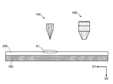
- FIG. 1 is a schematic view of a droplet ejection device 100 according to an embodiment of the present invention.
- the droplet ejection device 100 includes a control unit 110, a storage unit 115, a power supply unit 120, a driving unit 130, a first droplet ejection unit 140, a second droplet ejection unit 150, and an object holding unit 160.
- the control unit 110 includes a CPU (Central Processing Unit), an ASIC (Application Specific Integrated Circuit), an FPGA (Field Programmable Gate Array), or other arithmetic processing circuits.
- the control unit 110 controls the ejection process of the first droplet ejection unit 140 and the second droplet ejection unit 150 by using a preset droplet ejection program.
- the control unit 110 ejects the first droplet 147 (see FIG. 3) of the first droplet ejection unit 140 and the second droplet 157 (see FIG. 5) of the second droplet ejection unit 150. To control. Although the details will be described later, the ejection of the first droplet 147 by the first droplet ejection unit 140 and the ejection of the second droplet 157 of the second droplet ejection unit 150 are synchronized. "Synchronizing" in the present embodiment means that the first droplet and the second droplet are ejected at a constant cycle. In this example, the first droplet 147 and the second droplet 157 are ejected at the same time.
- the second droplet ejection unit 150 moves. It moves to the first region and is controlled to eject the second droplet 157.
- the storage unit 115 has a function as a droplet ejection program and a database for storing various information used in the droplet ejection program.
- a memory, SSD, or a storable element is used for the storage unit 115.
- the power supply unit 120 is connected to the control unit 110, the drive unit 130, the first droplet ejection unit 140, and the second droplet ejection unit 150.
- the power supply unit 120 applies a voltage to the first droplet ejection unit 140 and the second droplet ejection unit 150 based on the signal input from the control unit 110.
- the power supply unit 120 applies a pulsed voltage to the first droplet ejection unit 140.
- the voltage is not limited to the pulse voltage, and a constant voltage may be constantly applied.
- the drive unit 130 is composed of drive members such as a motor, a belt, and a gear. Based on the instruction from the control unit 110, the drive unit 130 moves the first droplet ejection unit 140 and the second droplet ejection unit 150 to predetermined positions on the object 200 in this example.
- the first droplet ejection unit 140 includes a first droplet nozzle 141 and a first ink tank 143 (also referred to as a first liquid holding unit).
- An electrostatic discharge type inkjet nozzle is used for the first droplet nozzle 141.
- the inner diameter of the nozzle tip portion 141a of the first droplet nozzle 141 is 100 nm or more and 30 ⁇ m or less, preferably 0.5 ⁇ m or more and 20 ⁇ m or less, and more preferably 1.5 ⁇ m or more and 10 ⁇ m or less.
- the first droplet nozzle 141 has a glass tube, and an electrode 145 is provided inside the glass tube.
- an electrode 145 is provided inside the glass tube.
- a thin tungsten wire is used for the electrode 145.
- the electrode 145 is not limited to tungsten, and nickel, molybdenum, titanium, gold, silver, copper, platinum, or the like may be provided.
- the electrode 145 of the first droplet nozzle 141 is electrically connected to the power supply unit 120.
- the first liquid held in the first ink tank 143 by the voltage (1000 V in this example) applied from the power supply unit 120 to the inside of the first droplet nozzle 141 and the electrode 145 is the first liquid droplet nozzle 141.
- the first droplet 147 is discharged from the nozzle tip 141a (also referred to as the first tip). By controlling the voltage applied from the power supply unit 120, the shape of the droplet (pattern) formed by the first droplet 147 can be controlled.
- the second droplet ejection unit 150 includes the second droplet nozzle 151 and the second ink tank 153.
- a piezo type inkjet nozzle is used for the second droplet nozzle 151.
- a piezoelectric element 155 is provided above the second droplet nozzle 151.
- the piezoelectric element 155 is electrically connected to the power supply unit 120.
- the piezoelectric element 155 presses the second liquid with the voltage applied from the power supply unit 120 to transfer the second liquid held in the second ink tank 153 to the nozzle tip portion 151a (first portion 151a) of the second droplet nozzle 151.
- the second droplet 157 is discharged from the tip portion).
- the second droplet nozzle 151 of the second droplet ejection unit 150 is provided perpendicular to the surface of the object 200.
- the inner diameter of the nozzle tip portion 151a of the second droplet nozzle 151 is wider than the inner diameter of the nozzle tip portion 151a of the second droplet nozzle 151. Therefore, the discharge amount of the second droplet discharge unit 150 per unit time can be made larger than the discharge amount of the first droplet discharge unit 140 per unit time.
- the object holding unit 160 has a function of holding the object 200.
- a stage is used in this example.
- the mechanism by which the object holding unit 160 holds the object 200 is not particularly limited, and a general holding mechanism is used.
- the object 200 is vacuum-sucked to the object holding portion 160.
- the object holding unit 160 may hold the object 200 by using a fixture.
- the first droplet ejection unit 140 and the second droplet ejection unit 150 are in the direction in which the first droplet ejection unit 140 and the second droplet ejection unit 150 move with respect to the object holding unit 160 (in this example, the first It is arranged along the direction (D1 direction)).
- the second droplet ejection portion 150 (more specifically, the nozzle tip portion 151a of the second droplet nozzle 151) is the first droplet ejection portion 140 (more specifically, the first droplet ejection portion 140) in the D1 direction. It is arranged behind the nozzle tip 141a) of the droplet nozzle 141.
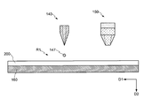
- the distance L between the first droplet ejection portion 140 and the second droplet ejection portion 150 can be appropriately adjusted.
- the first droplet ejection unit 140 and the second droplet ejection unit 150 move onto the object 200 prepared in the droplet ejection device 100 by the control unit 110 and the driving unit 130.
- the first droplet ejection portion 140 is arranged on the first region R1 of the object 200 at a certain distance from the surface.
- the object 200 refers to a member on which the first droplet 147 and the second droplet 157 are ejected.
- a flat glass plate is used for the object 200.
- the object 200 is not limited to a flat glass plate.
- it may be a metal plate or an organic resin member.
- the object 200 may be appropriately provided with a counter electrode.
- the first droplet ejection unit 140 ejects the first droplet 147 into the first region R1 in the D2 direction.
- a liquid material containing no particles is used for the first droplet 147.
- an organic solvent that does not contain particles such as pigments is used.
- the discharge amount of the first droplet 147 is preferably 0.1fl or more and 100pl or less, preferably 0.1fl or more and 10pl or less, and more preferably 0.3fl or more and 1pl or less. At this time, it is desirable that the size of the first droplet 147 landed on the object 200 is 100 nm or more and 500 ⁇ m or less.
- the first droplet 147 dropped on the object 200 is fixed to the object 200 before the second droplet 157 is discharged.
- the first droplet 147 is subjected to a pinning process. It is desirable that a light irradiation process is used for the pinning process. The wavelength of the emitted light is appropriately adjusted according to the material to be discharged.
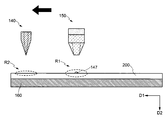
- the first droplet ejection portion 140 moves from the first region R1 to the second region R2 of the object 200.
- the second droplet ejection unit 150 moves on the first region R1 in which the first droplet 147 is ejected in accordance with the movement of the first droplet ejection unit 140.
- the moving speeds of the first droplet ejection unit 140 and the second droplet ejection unit 150 are the drying time of the first droplet 147 and the distance L between the first droplet ejection unit 140 and the second droplet ejection unit 150. It is desirable to set in advance in consideration of such factors.
- the first droplet ejection unit 140 ejects the first droplet 147 in the D2 direction to the second region R2 of the object 200, similarly to the first region R1.
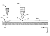
- the second droplet ejection unit 150 ejects the second droplet 157 to the first region R1 in the D2 direction in synchronization with the first droplet ejection unit 140 ejecting the first droplet 147 to the second region R2.
- the second droplet ejection unit 150 ejects the second droplet 157 at the same time that the first droplet ejection unit 140 ejects the first droplet 147.
- the second droplet 157 a material having a viscosity higher than that of the first droplet 147 is used. Specifically, a pattern-forming ink containing a pigment is used for the second droplet 157. It is desirable that the solvent of the first droplet 147 and the solvent of the second droplet 157 are the same kind of liquid. Further, the first droplet 147 does not contain the pigment particles, and the second droplet 157 may contain particles such as the pigment.
- the size of the second droplet 157 to be ejected is wider than the size of the first droplet 147. Further, it is desirable that the second droplet 157 is discharged so as to come into contact with the first droplet 147. Further, the surface of the object 200 preferably has liquid repellency against the second droplet 157.
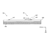
- FIG. 7 is a cross-sectional view when the second droplet 157 is ejected in the first region R1 with a deviation from a predetermined position.
- the surface energy is minimized.
- the second droplet 157 can be moved and repositioned (realigned) so as to capture the pinned first droplet 147 in order to achieve the conversion. As a result, even if the ejection position of the second droplet 157 deviates, the alignment can be performed at the target position.
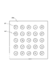
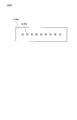
- FIG. 8 is a top view of the object 200 after the droplet is discharged. As shown in FIG. 8, the pattern (first droplet and second droplet 157) can be arranged at a desired position of the object 200.
- the electrostatic ejection type inkjet method is a technology capable of ejecting minute droplets and having excellent position accuracy and resolution, but there is a trade-off between reduction of tact time and increase of throughput.
- the position of the large second droplet ejected by the piezo inkjet head is controlled by the first droplet whose position is controlled with high accuracy by the electrostatic ejection type inkjet and landed. It becomes. That is, by using this embodiment, it is possible to achieve both high definition, high precision, and high productivity.
- a solvent containing no particles is discharged as the first droplet from the electrostatic discharge type inkjet head.
- the liquid (ink) having particles for pattern formation is discharged from the piezo type inkjet head having an inner diameter larger than the inner diameter of the tip portion of the electrostatic discharge type inkjet nozzle. Therefore, it is possible to prevent clogging of the inkjet nozzle due to particles (solid matter).
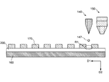
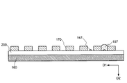
- the structure 170 (also referred to as a pattern or structure) provided on the surface of the object 200 is provided as an organic insulating layer.
- the organic insulating layer used for the structure 170 is not particularly limited, but in this example, a polyimide resin is used for the structure 170.
- the structure 170 may be an organic resin such as an acrylic resin or an epoxy resin, or an inorganic material such as silicon oxide (SiO x ), silicon nitride (SiN x ), or aluminum oxide (AlO x ) is used. May be good.
- the structure 170 is provided in a grid shape so as to expose a part of the surface of the object 200. Therefore, each of the first region R1 and the second region R2 from which the first droplet 147 and the second droplet 157 are discharged is surrounded by the structure 170.
- the surface of the object 200 has a liquid-like property and the surface of the structure 170 has a liquid-repellent property. Therefore, it is desirable to appropriately select the optimum material for the object 200.
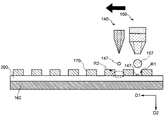
- the first droplet ejection portion 140 is arranged on the first region R1.
- the first droplet ejection unit 140 ejects the first droplet 147 into the first region R1.
- the first droplet 147 lands on the first region R1 (more specifically, a preset position within the first region R1) on the surface of the object 200.
- the first droplet ejection portion 140 moves from the first region R1 to the second region R2 of the object 200.
- the second droplet ejection unit 150 moves onto the first region R1 where the first droplet 147 is ejected.
- the first droplet ejection unit 140 ejects the first droplet 147 to the second region R2 of the object 200 in the same manner as the first region R1.
- the second droplet ejection unit 150 ejects the second droplet 157 to the first region R1 in synchronization with the first droplet ejection unit 140 ejecting the first droplet 147 to the second region R2.
- the second droplet ejection unit 150 ejects the second droplet 157 at the same time that the first droplet ejection unit 140 ejects the first droplet. At this time, it is desirable that the second droplet 157 is ejected so as to come into contact with the first droplet 147.
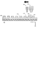
- the second droplet 157 When the second droplet 157 is ejected at a predetermined position, as shown in FIG. 12, the second droplet 157 lands on the surface of the object 200 inside the grid structure provided by the structure 170. .. On the other hand, as shown in FIG. 13, the second droplet 157 may be ejected at a position deviated from a predetermined position. In this case, when the second droplet 157 is in contact with the first droplet 147, the second droplet 157 is taken in so as to take in the pinned first droplet 147 in order to minimize the surface energy. The portion existing on the structure 170 of the above moves to the object 200, and the position of the entire second droplet 157 is changed (realigned).
- the second droplet 157 can be aligned with the target position. This phenomenon is effective when the surface of the object 200 is liquid-repellent and the surface of the structure is liquid-repellent, because the second droplet 157 easily moves.
- the first droplet ejection unit 140 and the second droplet ejection unit 150 target the first droplet 147 and the second droplet 157, not on the structure 170, as shown in FIG. It is provided on the surface of the object 200.
- a pattern forming apparatus different from that of the first embodiment will be described. Specifically, an example in which a plurality of first droplet nozzles 141 and second droplet nozzles 151 are provided will be described. For the sake of explanation, the members will be omitted as appropriate.
- FIG. 15 is a schematic view of the droplet ejection device 100A according to the embodiment of the present invention.
- the droplet ejection device 100A includes a control unit 110, a storage unit 115, a power supply unit 120, a driving unit 130, a first droplet ejection unit 140A, and a second droplet ejection unit 150A.
- FIG. 16 is a top view of the first droplet nozzle 141C.
- FIG. 17 is an enlarged top view and cross-sectional view of a part of the first droplet nozzle 141C.
- the first droplet nozzle 141B has a plurality of nozzle portions 141Bb and a plate portion 141Bc.
- a plurality of nozzle portions 141Bb are arranged side by side in one row, but they may be arranged side by side in a plurality of rows.
- a metal material such as nickel is used for the nozzle portion 141Bb.
- the nozzle portion 141Bb is formed, for example, by an electroforming method so as to have a tapered shape.
- a metal material such as stainless steel is used for the plate portion 141Bc.
- the plate portion 141Bc has a hole having an inner diameter r141Bc larger than the inner diameter r141Ba of the nozzle tip portion 141Ba of the nozzle portion 141Bb in a portion overlapping the nozzle portion 141Bb.
- the nozzle portion 141Bb may be welded to the plate portion 141Bc, or may be fixed with an adhesive.
- a voltage may be applied to the nozzle portion 141Bb, or a voltage may be applied to the plate portion 141Bc (or the first ink tank 143).
- the present invention is not limited thereto.
- the drive unit 130 may move the object 200.
- the first droplet ejection portion 140 and the second droplet ejection portion 150 may be fixed at the same position.
- the structure 170 may have a wiring pattern or an inorganic material may be used.
- the object 200 itself may be processed to provide a structure.
- the object 200 may be a wiring board on which wirings are laminated.
- the second droplet 157 is discharged so as to come into contact with the first droplet 147, but the present invention is not limited to this.
- the second droplet 157 is also applicable when it is ejected in the vicinity of the first droplet 147.
- an electrostatic discharge type nozzle is used for the first droplet nozzle 141
- the present invention is not limited to this.
- a piezo type inkjet nozzle may be used for the first droplet nozzle 141 as long as the position can be controlled.
- the pinning process may be performed using heat.
- an aqueous solution containing a metal salt may be used for the first droplet 147.
- the metal salt a calcium salt, a sodium salt and the like are used. Since the first droplet contains a metal salt, the metal salt is deposited when the water content of the first droplet evaporates, and the pinning property is enhanced.
- Droplet ejection device 110 ... Control unit, 115 ... Storage unit, 120 ... Power supply unit, 130 ... Drive unit, 140 ... First droplet ejection unit, 141. .. 1st droplet nozzle, 141a ... nozzle tip, 143 ... 1st ink tank, 145 ... electrode, 147 ... 1st droplet, 150 ... 2nd droplet ejection part , 151 ... second droplet nozzle, 151a ... nozzle tip, 153 ... second ink tank, 155 ... piezoelectric element, 157 ... second droplet, 160 ... object Holding part, 170 ... structure, 200 ... object
Landscapes
- Coating Apparatus (AREA)
- Application Of Or Painting With Fluid Materials (AREA)
- Ink Jet (AREA)
Priority Applications (5)
| Application Number | Priority Date | Filing Date | Title |
|---|---|---|---|
| CN202080003001.5A CN112166040B (zh) | 2019-04-25 | 2020-03-10 | 液滴喷出装置以及液滴喷出方法 |
| KR1020207032373A KR102381833B1 (ko) | 2019-04-25 | 2020-03-10 | 액적 토출 장치 및 액적 토출 방법 |
| EP20795860.4A EP3960466A4 (en) | 2019-04-25 | 2020-03-10 | LIQUID DROP EJECTING DEVICE AND LIQUID DROP EJECTING METHOD |
| US17/100,193 US11351784B2 (en) | 2019-04-25 | 2020-11-20 | Liquid droplet ejection device and liquid droplet ejection method |
| IL287162A IL287162B2 (en) | 2019-04-25 | 2021-10-11 | Liquid droplet release device and liquid droplet release method |
Applications Claiming Priority (2)
| Application Number | Priority Date | Filing Date | Title |
|---|---|---|---|
| JP2019-084650 | 2019-04-25 | ||
| JP2019084650A JP7351501B2 (ja) | 2019-04-25 | 2019-04-25 | 液滴吐出装置および液滴吐出方法 |
Related Child Applications (1)
| Application Number | Title | Priority Date | Filing Date |
|---|---|---|---|
| US17/100,193 Continuation US11351784B2 (en) | 2019-04-25 | 2020-11-20 | Liquid droplet ejection device and liquid droplet ejection method |
Publications (1)
| Publication Number | Publication Date |
|---|---|
| WO2020217756A1 true WO2020217756A1 (ja) | 2020-10-29 |
Family
ID=72942453
Family Applications (1)
| Application Number | Title | Priority Date | Filing Date |
|---|---|---|---|
| PCT/JP2020/010369 WO2020217756A1 (ja) | 2019-04-25 | 2020-03-10 | 液滴吐出装置および液滴吐出方法 |
Country Status (7)
Cited By (1)
| Publication number | Priority date | Publication date | Assignee | Title |
|---|---|---|---|---|
| WO2023181683A1 (ja) * | 2022-03-23 | 2023-09-28 | 株式会社Sijテクノロジ | 液滴吐出装置および液滴吐出方法 |
Citations (6)
| Publication number | Priority date | Publication date | Assignee | Title |
|---|---|---|---|---|
| JPH1034967A (ja) | 1996-07-19 | 1998-02-10 | Fuji Xerox Co Ltd | インクジェット記録装置 |
| JP2004114380A (ja) * | 2002-09-24 | 2004-04-15 | Konica Minolta Holdings Inc | 溶液吐出式医用画像記録方法及び溶液吐出式医用画像記録装置 |
| JP2008213221A (ja) * | 2007-03-01 | 2008-09-18 | Seiko Epson Corp | 液体吐出装置、液体吐出方法、及び、プログラム |
| WO2010028712A1 (en) * | 2008-09-11 | 2010-03-18 | ETH Zürich | Capillarity-assisted, mask-less, nano-/micro-scale spray deposition of particle based functional 0d to 3d micro- and nanostructures on flat or curved substrates with or without added electrocapillarity effect |
| WO2016124814A1 (en) * | 2015-02-06 | 2016-08-11 | Nokia Technologies Oy | A quantum dot apparatus and associated methods and apparatus |
| JP2016210184A (ja) * | 2015-05-11 | 2016-12-15 | 株式会社リコー | 液体を吐出する装置 |
Family Cites Families (17)
| Publication number | Priority date | Publication date | Assignee | Title |
|---|---|---|---|---|
| JPH1086363A (ja) * | 1996-09-11 | 1998-04-07 | Minolta Co Ltd | インクジェット記録ヘッドおよびインクジェット記録装置 |
| JPH10130558A (ja) * | 1996-09-03 | 1998-05-19 | Fujitsu Isotec Ltd | 水性顔料系インク及びインクジェットプリンタ |
| DE60330297D1 (de) * | 2002-07-30 | 2010-01-14 | Fujifilm Corp | Elektrostatischer Tintenstrahldruckkopf |
| EP1550556B1 (en) | 2002-09-24 | 2010-02-24 | Konica Minolta Holdings, Inc. | Method for manufacturing electrostatic attraction type liquid discharge head, method for manufacturing nozzle plate. |
| JP4397642B2 (ja) * | 2003-08-08 | 2010-01-13 | シャープ株式会社 | 静電吸引型流体吐出方法およびその装置 |
| US7712874B2 (en) | 2003-08-08 | 2010-05-11 | Sharp Kabushiki Kaisha | Electrostatic suction type fluid discharge device, electrostatic suction type fluid discharge method, and plot pattern formation method using the same |
| KR100678419B1 (ko) | 2005-04-01 | 2007-02-02 | 삼성전기주식회사 | 기판의 표면처리방법, 배선형성방법 및 배선기판 |
| JP2007271811A (ja) * | 2006-03-30 | 2007-10-18 | Dainippon Printing Co Ltd | カラーフィルターの製造方法 |
| JP2008168438A (ja) | 2007-01-09 | 2008-07-24 | Seiko Epson Corp | 静電アクチュエータ、液滴吐出ヘッド及びそれらの製造方法並びに液滴吐出装置 |
| WO2009057464A1 (ja) * | 2007-11-01 | 2009-05-07 | Konica Minolta Holdings, Inc. | 塗布方法及び塗布装置 |
| KR101567506B1 (ko) | 2009-02-04 | 2015-11-10 | 삼성전자주식회사 | 잉크젯 프린팅 장치 및 그 구동 방법 |
| JP5413826B2 (ja) * | 2009-02-17 | 2014-02-12 | 株式会社マイクロジェット | 吐出装置 |
| JP5376136B2 (ja) * | 2009-04-02 | 2013-12-25 | ソニー株式会社 | パターン形成方法 |
| JP5189664B2 (ja) * | 2011-03-07 | 2013-04-24 | 富士フイルム株式会社 | 画像処理装置及び方法、並びに画像形成装置 |
| JP5899794B2 (ja) * | 2011-10-21 | 2016-04-06 | セイコーエプソン株式会社 | 印刷物の製造方法、印刷物 |
| KR20150144257A (ko) * | 2014-10-21 | 2015-12-24 | 김영 | 도트 방식으로 코팅된 주방기구 및 그 제조방법 |
| KR20160080452A (ko) * | 2014-12-29 | 2016-07-08 | 주식회사 케이씨텍 | 기판 코터 장치 및 이를 이용한 기판 코팅방법 |
-
2019
- 2019-04-25 JP JP2019084650A patent/JP7351501B2/ja active Active
-
2020
- 2020-03-10 WO PCT/JP2020/010369 patent/WO2020217756A1/ja unknown
- 2020-03-10 EP EP20795860.4A patent/EP3960466A4/en active Pending
- 2020-03-10 KR KR1020207032373A patent/KR102381833B1/ko active Active
- 2020-03-10 CN CN202080003001.5A patent/CN112166040B/zh active Active
- 2020-11-20 US US17/100,193 patent/US11351784B2/en active Active
-
2021
- 2021-10-11 IL IL287162A patent/IL287162B2/en unknown
Patent Citations (6)
| Publication number | Priority date | Publication date | Assignee | Title |
|---|---|---|---|---|
| JPH1034967A (ja) | 1996-07-19 | 1998-02-10 | Fuji Xerox Co Ltd | インクジェット記録装置 |
| JP2004114380A (ja) * | 2002-09-24 | 2004-04-15 | Konica Minolta Holdings Inc | 溶液吐出式医用画像記録方法及び溶液吐出式医用画像記録装置 |
| JP2008213221A (ja) * | 2007-03-01 | 2008-09-18 | Seiko Epson Corp | 液体吐出装置、液体吐出方法、及び、プログラム |
| WO2010028712A1 (en) * | 2008-09-11 | 2010-03-18 | ETH Zürich | Capillarity-assisted, mask-less, nano-/micro-scale spray deposition of particle based functional 0d to 3d micro- and nanostructures on flat or curved substrates with or without added electrocapillarity effect |
| WO2016124814A1 (en) * | 2015-02-06 | 2016-08-11 | Nokia Technologies Oy | A quantum dot apparatus and associated methods and apparatus |
| JP2016210184A (ja) * | 2015-05-11 | 2016-12-15 | 株式会社リコー | 液体を吐出する装置 |
Non-Patent Citations (1)
| Title |
|---|
| See also references of EP3960466A4 |
Cited By (1)
| Publication number | Priority date | Publication date | Assignee | Title |
|---|---|---|---|---|
| WO2023181683A1 (ja) * | 2022-03-23 | 2023-09-28 | 株式会社Sijテクノロジ | 液滴吐出装置および液滴吐出方法 |
Also Published As
| Publication number | Publication date |
|---|---|
| EP3960466A4 (en) | 2022-12-28 |
| KR20200140892A (ko) | 2020-12-16 |
| EP3960466A1 (en) | 2022-03-02 |
| US20210070047A1 (en) | 2021-03-11 |
| US11351784B2 (en) | 2022-06-07 |
| CN112166040B (zh) | 2022-05-13 |
| CN112166040A (zh) | 2021-01-01 |
| JP2020179602A (ja) | 2020-11-05 |
| JP7351501B2 (ja) | 2023-09-27 |
| KR102381833B1 (ko) | 2022-04-01 |
| IL287162A (en) | 2021-12-01 |
| IL287162B2 (en) | 2025-08-01 |
| IL287162B1 (en) | 2025-04-01 |
Similar Documents
| Publication | Publication Date | Title |
|---|---|---|
| JP4437805B2 (ja) | インク吐出装置及びインク吐出制御方法 | |
| JP2008094044A (ja) | ヘッドユニットおよび液滴吐出装置、液状体の吐出方法、カラーフィルタの製造方法、有機el素子の製造方法、配線基板の製造方法 | |
| US11376847B2 (en) | Liquid droplet ejection device and liquid droplet ejection method | |
| CN100333908C (zh) | 喷出装置、材料涂覆方法、滤色片基板的制造方法 | |
| JP2017056402A (ja) | 液滴吐出方法、液滴吐出プログラム、液滴吐出装置 | |
| JP6052617B2 (ja) | インクジェット装置 | |
| CN114423614B (zh) | 液滴喷出装置及液滴喷出方法 | |
| US20170062719A1 (en) | Droplet discharge method, program, manufacturing method of organic el device, forming method of color filter | |
| WO2020217756A1 (ja) | 液滴吐出装置および液滴吐出方法 | |
| US9533498B2 (en) | Printing method and printing device | |
| JP2012148213A (ja) | インクジェット塗布方法および塗布装置 | |
| JP2017094235A (ja) | 液滴吐出方法および液滴吐出プログラム | |
| JP2009198938A (ja) | 液滴吐出装置、液状体の吐出方法、カラーフィルタの製造方法、有機el素子の製造方法 | |
| US20250214338A1 (en) | Liquid droplet ejection device, liquid droplet ejection nozzle head, and liquid droplet ejection method | |
| WO2023181683A1 (ja) | 液滴吐出装置および液滴吐出方法 | |
| WO2013084640A1 (ja) | 回路基板及び回路パターンの形成方法 | |
| WO2024080118A1 (ja) | 液滴吐出方法および液滴吐出装置 | |
| JP2016155062A (ja) | 液滴吐出方法、有機半導体素子の製造方法、制御プログラム | |
| JP2003255848A (ja) | 機能性素子基板の製造装置および機能性素子基板、ならびに該機能性素子基板を用いた画像表示装置 | |
| KR20120079733A (ko) | 박막트랜지스터 인쇄장치 및 이를 이용한 박막트랜지스터 인쇄방법 | |
| JP2003251244A (ja) | 機能性素子基板及び画像表示装置 | |
| JP2017125945A (ja) | 液滴吐出方法 | |
| JP2003257616A (ja) | 機能性素子基板および該機能性素子基板を用いた画像表示装置 |
Legal Events
| Date | Code | Title | Description |
|---|---|---|---|
| ENP | Entry into the national phase |
Ref document number: 20207032373 Country of ref document: KR Kind code of ref document: A |
|
| 121 | Ep: the epo has been informed by wipo that ep was designated in this application |
Ref document number: 20795860 Country of ref document: EP Kind code of ref document: A1 |
|
| NENP | Non-entry into the national phase |
Ref country code: DE |
|
| ENP | Entry into the national phase |
Ref document number: 2020795860 Country of ref document: EP Effective date: 20211125 |