EP1550556B1 - Method for manufacturing electrostatic attraction type liquid discharge head, method for manufacturing nozzle plate. - Google Patents
Method for manufacturing electrostatic attraction type liquid discharge head, method for manufacturing nozzle plate. Download PDFInfo
- Publication number
- EP1550556B1 EP1550556B1 EP03798450A EP03798450A EP1550556B1 EP 1550556 B1 EP1550556 B1 EP 1550556B1 EP 03798450 A EP03798450 A EP 03798450A EP 03798450 A EP03798450 A EP 03798450A EP 1550556 B1 EP1550556 B1 EP 1550556B1
- Authority
- EP
- European Patent Office
- Prior art keywords
- nozzle
- jetting
- liquid solution
- liquid
- voltage
- Prior art date
- Legal status (The legal status is an assumption and is not a legal conclusion. Google has not performed a legal analysis and makes no representation as to the accuracy of the status listed.)
- Expired - Lifetime
Links
- 238000000034 method Methods 0.000 title claims abstract description 57
- 239000007788 liquid Substances 0.000 title claims description 243
- 238000004519 manufacturing process Methods 0.000 title description 11
- 239000006193 liquid solution Substances 0.000 claims description 421
- 229920005989 resin Polymers 0.000 claims description 108
- 239000011347 resin Substances 0.000 claims description 108
- 230000005499 meniscus Effects 0.000 claims description 69
- 239000000463 material Substances 0.000 claims description 59
- YCKRFDGAMUMZLT-UHFFFAOYSA-N Fluorine atom Chemical compound [F] YCKRFDGAMUMZLT-UHFFFAOYSA-N 0.000 claims description 24
- 229910052731 fluorine Inorganic materials 0.000 claims description 24
- 239000011737 fluorine Substances 0.000 claims description 24
- 238000004891 communication Methods 0.000 claims description 8
- 230000008569 process Effects 0.000 abstract description 5
- 238000005530 etching Methods 0.000 abstract description 3
- 238000000206 photolithography Methods 0.000 abstract description 3
- 239000000758 substrate Substances 0.000 abstract 3
- 238000004140 cleaning Methods 0.000 description 116
- 239000010410 layer Substances 0.000 description 104
- 230000005684 electric field Effects 0.000 description 94
- XLYOFNOQVPJJNP-UHFFFAOYSA-N water Substances O XLYOFNOQVPJJNP-UHFFFAOYSA-N 0.000 description 85
- 238000000576 coating method Methods 0.000 description 83
- 239000011248 coating agent Substances 0.000 description 78
- 239000002904 solvent Substances 0.000 description 71
- 230000002940 repellent Effects 0.000 description 59
- 239000005871 repellent Substances 0.000 description 59
- 235000021251 pulses Nutrition 0.000 description 50
- 230000015572 biosynthetic process Effects 0.000 description 34
- 230000004888 barrier function Effects 0.000 description 30
- PPBRXRYQALVLMV-UHFFFAOYSA-N Styrene Chemical compound C=CC1=CC=CC=C1 PPBRXRYQALVLMV-UHFFFAOYSA-N 0.000 description 28
- 229920001577 copolymer Polymers 0.000 description 28
- 239000010419 fine particle Substances 0.000 description 28
- -1 polymethylsiloxane Polymers 0.000 description 24
- 230000000694 effects Effects 0.000 description 23
- 230000004043 responsiveness Effects 0.000 description 20
- 239000006185 dispersion Substances 0.000 description 19
- 238000009826 distribution Methods 0.000 description 19
- 229920000642 polymer Polymers 0.000 description 17
- 238000012545 processing Methods 0.000 description 16
- 239000002344 surface layer Substances 0.000 description 16
- 229920002554 vinyl polymer Polymers 0.000 description 16
- ISWSIDIOOBJBQZ-UHFFFAOYSA-N Phenol Chemical compound OC1=CC=CC=C1 ISWSIDIOOBJBQZ-UHFFFAOYSA-N 0.000 description 14
- OISVCGZHLKNMSJ-UHFFFAOYSA-N 2,6-dimethylpyridine Chemical compound CC1=CC=CC(C)=N1 OISVCGZHLKNMSJ-UHFFFAOYSA-N 0.000 description 12
- QTBSBXVTEAMEQO-UHFFFAOYSA-N Acetic acid Chemical compound CC(O)=O QTBSBXVTEAMEQO-UHFFFAOYSA-N 0.000 description 12
- CSCPPACGZOOCGX-UHFFFAOYSA-N Acetone Chemical compound CC(C)=O CSCPPACGZOOCGX-UHFFFAOYSA-N 0.000 description 12
- WEVYAHXRMPXWCK-UHFFFAOYSA-N Acetonitrile Chemical compound CC#N WEVYAHXRMPXWCK-UHFFFAOYSA-N 0.000 description 12
- UHOVQNZJYSORNB-UHFFFAOYSA-N Benzene Chemical compound C1=CC=CC=C1 UHOVQNZJYSORNB-UHFFFAOYSA-N 0.000 description 12
- XEKOWRVHYACXOJ-UHFFFAOYSA-N Ethyl acetate Chemical compound CCOC(C)=O XEKOWRVHYACXOJ-UHFFFAOYSA-N 0.000 description 12
- LYCAIKOWRPUZTN-UHFFFAOYSA-N Ethylene glycol Chemical compound OCCO LYCAIKOWRPUZTN-UHFFFAOYSA-N 0.000 description 12
- OKKJLVBELUTLKV-UHFFFAOYSA-N Methanol Chemical compound OC OKKJLVBELUTLKV-UHFFFAOYSA-N 0.000 description 12
- ZMXDDKWLCZADIW-UHFFFAOYSA-N N,N-Dimethylformamide Chemical compound CN(C)C=O ZMXDDKWLCZADIW-UHFFFAOYSA-N 0.000 description 12
- AFBPFSWMIHJQDM-UHFFFAOYSA-N N-methylaniline Chemical compound CNC1=CC=CC=C1 AFBPFSWMIHJQDM-UHFFFAOYSA-N 0.000 description 12
- JFDZBHWFFUWGJE-UHFFFAOYSA-N benzonitrile Chemical compound N#CC1=CC=CC=C1 JFDZBHWFFUWGJE-UHFFFAOYSA-N 0.000 description 12
- MTHSVFCYNBDYFN-UHFFFAOYSA-N diethylene glycol Chemical compound OCCOCCO MTHSVFCYNBDYFN-UHFFFAOYSA-N 0.000 description 12
- 229910052751 metal Inorganic materials 0.000 description 12
- 239000002184 metal Substances 0.000 description 12
- 238000007639 printing Methods 0.000 description 12
- 238000007747 plating Methods 0.000 description 11
- 230000008859 change Effects 0.000 description 10
- 239000004020 conductor Substances 0.000 description 10
- 239000011810 insulating material Substances 0.000 description 10
- XUIMIQQOPSSXEZ-UHFFFAOYSA-N Silicon Chemical compound [Si] XUIMIQQOPSSXEZ-UHFFFAOYSA-N 0.000 description 9
- 230000007423 decrease Effects 0.000 description 9
- 238000002474 experimental method Methods 0.000 description 9
- 239000011159 matrix material Substances 0.000 description 9
- 238000000059 patterning Methods 0.000 description 9
- 229910052710 silicon Inorganic materials 0.000 description 9
- 239000010703 silicon Substances 0.000 description 9
- 238000012360 testing method Methods 0.000 description 9
- ZWEHNKRNPOVVGH-UHFFFAOYSA-N 2-Butanone Chemical compound CCC(C)=O ZWEHNKRNPOVVGH-UHFFFAOYSA-N 0.000 description 8
- BSKHPKMHTQYZBB-UHFFFAOYSA-N 2-methylpyridine Chemical compound CC1=CC=CC=N1 BSKHPKMHTQYZBB-UHFFFAOYSA-N 0.000 description 8
- RSWGJHLUYNHPMX-UHFFFAOYSA-N Abietic-Saeure Natural products C12CCC(C(C)C)=CC2=CCC2C1(C)CCCC2(C)C(O)=O RSWGJHLUYNHPMX-UHFFFAOYSA-N 0.000 description 8
- DLFVBJFMPXGRIB-UHFFFAOYSA-N Acetamide Chemical compound CC(N)=O DLFVBJFMPXGRIB-UHFFFAOYSA-N 0.000 description 8
- KWOLFJPFCHCOCG-UHFFFAOYSA-N Acetophenone Chemical compound CC(=O)C1=CC=CC=C1 KWOLFJPFCHCOCG-UHFFFAOYSA-N 0.000 description 8
- PAYRUJLWNCNPSJ-UHFFFAOYSA-N Aniline Chemical compound NC1=CC=CC=C1 PAYRUJLWNCNPSJ-UHFFFAOYSA-N 0.000 description 8
- XTHFKEDIFFGKHM-UHFFFAOYSA-N Dimethoxyethane Chemical compound COCCOC XTHFKEDIFFGKHM-UHFFFAOYSA-N 0.000 description 8
- NIQCNGHVCWTJSM-UHFFFAOYSA-N Dimethyl phthalate Chemical compound COC(=O)C1=CC=CC=C1C(=O)OC NIQCNGHVCWTJSM-UHFFFAOYSA-N 0.000 description 8
- IAZDPXIOMUYVGZ-UHFFFAOYSA-N Dimethylsulphoxide Chemical compound CS(C)=O IAZDPXIOMUYVGZ-UHFFFAOYSA-N 0.000 description 8
- VGGSQFUCUMXWEO-UHFFFAOYSA-N Ethene Chemical compound C=C VGGSQFUCUMXWEO-UHFFFAOYSA-N 0.000 description 8
- QUSNBJAOOMFDIB-UHFFFAOYSA-N Ethylamine Chemical compound CCN QUSNBJAOOMFDIB-UHFFFAOYSA-N 0.000 description 8
- 239000005977 Ethylene Substances 0.000 description 8
- ZHNUHDYFZUAESO-UHFFFAOYSA-N Formamide Chemical compound NC=O ZHNUHDYFZUAESO-UHFFFAOYSA-N 0.000 description 8
- PEDCQBHIVMGVHV-UHFFFAOYSA-N Glycerine Chemical compound OCC(O)CO PEDCQBHIVMGVHV-UHFFFAOYSA-N 0.000 description 8
- KFZMGEQAYNKOFK-UHFFFAOYSA-N Isopropanol Chemical compound CC(C)O KFZMGEQAYNKOFK-UHFFFAOYSA-N 0.000 description 8
- JLTDJTHDQAWBAV-UHFFFAOYSA-N N,N-dimethylaniline Chemical compound CN(C)C1=CC=CC=C1 JLTDJTHDQAWBAV-UHFFFAOYSA-N 0.000 description 8
- LRHPLDYGYMQRHN-UHFFFAOYSA-N N-Butanol Chemical compound CCCCO LRHPLDYGYMQRHN-UHFFFAOYSA-N 0.000 description 8
- ATHHXGZTWNVVOU-UHFFFAOYSA-N N-methylformamide Chemical compound CNC=O ATHHXGZTWNVVOU-UHFFFAOYSA-N 0.000 description 8
- UFWIBTONFRDIAS-UHFFFAOYSA-N Naphthalene Chemical compound C1=CC=CC2=CC=CC=C21 UFWIBTONFRDIAS-UHFFFAOYSA-N 0.000 description 8
- NQRYJNQNLNOLGT-UHFFFAOYSA-N Piperidine Chemical compound C1CCNCC1 NQRYJNQNLNOLGT-UHFFFAOYSA-N 0.000 description 8
- XBDQKXXYIPTUBI-UHFFFAOYSA-M Propionate Chemical compound CCC([O-])=O XBDQKXXYIPTUBI-UHFFFAOYSA-M 0.000 description 8
- JUJWROOIHBZHMG-UHFFFAOYSA-N Pyridine Chemical compound C1=CC=NC=C1 JUJWROOIHBZHMG-UHFFFAOYSA-N 0.000 description 8
- SMWDFEZZVXVKRB-UHFFFAOYSA-N Quinoline Chemical compound N1=CC=CC2=CC=CC=C21 SMWDFEZZVXVKRB-UHFFFAOYSA-N 0.000 description 8
- KHPCPRHQVVSZAH-HUOMCSJISA-N Rosin Natural products O(C/C=C/c1ccccc1)[C@H]1[C@H](O)[C@@H](O)[C@@H](O)[C@@H](CO)O1 KHPCPRHQVVSZAH-HUOMCSJISA-N 0.000 description 8
- DKGAVHZHDRPRBM-UHFFFAOYSA-N Tert-Butanol Chemical compound CC(C)(C)O DKGAVHZHDRPRBM-UHFFFAOYSA-N 0.000 description 8
- 239000011230 binding agent Substances 0.000 description 8
- DIKBFYAXUHHXCS-UHFFFAOYSA-N bromoform Chemical compound BrC(Br)Br DIKBFYAXUHHXCS-UHFFFAOYSA-N 0.000 description 8
- DKPFZGUDAPQIHT-UHFFFAOYSA-N butyl acetate Chemical compound CCCCOC(C)=O DKPFZGUDAPQIHT-UHFFFAOYSA-N 0.000 description 8
- FLKPEMZONWLCSK-UHFFFAOYSA-N diethyl phthalate Chemical compound CCOC(=O)C1=CC=CC=C1C(=O)OCC FLKPEMZONWLCSK-UHFFFAOYSA-N 0.000 description 8
- 150000002148 esters Chemical class 0.000 description 8
- LZCLXQDLBQLTDK-UHFFFAOYSA-N ethyl 2-hydroxypropanoate Chemical compound CCOC(=O)C(C)O LZCLXQDLBQLTDK-UHFFFAOYSA-N 0.000 description 8
- FKRCODPIKNYEAC-UHFFFAOYSA-N ethyl propionate Chemical compound CCOC(=O)CC FKRCODPIKNYEAC-UHFFFAOYSA-N 0.000 description 8
- 238000001704 evaporation Methods 0.000 description 8
- HYBBIBNJHNGZAN-UHFFFAOYSA-N furfural Chemical compound O=CC1=CC=CO1 HYBBIBNJHNGZAN-UHFFFAOYSA-N 0.000 description 8
- 229920001519 homopolymer Polymers 0.000 description 8
- ZXEKIIBDNHEJCQ-UHFFFAOYSA-N isobutanol Chemical compound CC(C)CO ZXEKIIBDNHEJCQ-UHFFFAOYSA-N 0.000 description 8
- 150000002576 ketones Chemical class 0.000 description 8
- 239000004973 liquid crystal related substance Substances 0.000 description 8
- RLSSMJSEOOYNOY-UHFFFAOYSA-N m-cresol Chemical compound CC1=CC=CC(O)=C1 RLSSMJSEOOYNOY-UHFFFAOYSA-N 0.000 description 8
- BDAGIHXWWSANSR-UHFFFAOYSA-N methanoic acid Natural products OC=O BDAGIHXWWSANSR-UHFFFAOYSA-N 0.000 description 8
- TZIHFWKZFHZASV-UHFFFAOYSA-N methyl formate Chemical compound COC=O TZIHFWKZFHZASV-UHFFFAOYSA-N 0.000 description 8
- LQNUZADURLCDLV-UHFFFAOYSA-N nitrobenzene Chemical compound [O-][N+](=O)C1=CC=CC=C1 LQNUZADURLCDLV-UHFFFAOYSA-N 0.000 description 8
- QWVGKYWNOKOFNN-UHFFFAOYSA-N o-cresol Chemical compound CC1=CC=CC=C1O QWVGKYWNOKOFNN-UHFFFAOYSA-N 0.000 description 8
- RNVCVTLRINQCPJ-UHFFFAOYSA-N o-toluidine Chemical compound CC1=CC=CC=C1N RNVCVTLRINQCPJ-UHFFFAOYSA-N 0.000 description 8
- IWDCLRJOBJJRNH-UHFFFAOYSA-N p-cresol Chemical compound CC1=CC=C(O)C=C1 IWDCLRJOBJJRNH-UHFFFAOYSA-N 0.000 description 8
- HFPZCAJZSCWRBC-UHFFFAOYSA-N p-cymene Chemical compound CC(C)C1=CC=C(C)C=C1 HFPZCAJZSCWRBC-UHFFFAOYSA-N 0.000 description 8
- RZXMPPFPUUCRFN-UHFFFAOYSA-N p-toluidine Chemical compound CC1=CC=C(N)C=C1 RZXMPPFPUUCRFN-UHFFFAOYSA-N 0.000 description 8
- PGMYKACGEOXYJE-UHFFFAOYSA-N pentyl acetate Chemical compound CCCCCOC(C)=O PGMYKACGEOXYJE-UHFFFAOYSA-N 0.000 description 8
- 229920003229 poly(methyl methacrylate) Polymers 0.000 description 8
- 239000004926 polymethyl methacrylate Substances 0.000 description 8
- 239000011118 polyvinyl acetate Substances 0.000 description 8
- 229940075065 polyvinyl acetate Drugs 0.000 description 8
- 229920002689 polyvinyl acetate Polymers 0.000 description 8
- BDERNNFJNOPAEC-UHFFFAOYSA-N propan-1-ol Chemical compound CCCO BDERNNFJNOPAEC-UHFFFAOYSA-N 0.000 description 8
- 239000004065 semiconductor Substances 0.000 description 8
- FYSNRJHAOHDILO-UHFFFAOYSA-N thionyl chloride Chemical compound ClS(Cl)=O FYSNRJHAOHDILO-UHFFFAOYSA-N 0.000 description 8
- KHPCPRHQVVSZAH-UHFFFAOYSA-N trans-cinnamyl beta-D-glucopyranoside Natural products OC1C(O)C(O)C(CO)OC1OCC=CC1=CC=CC=C1 KHPCPRHQVVSZAH-UHFFFAOYSA-N 0.000 description 8
- 239000000853 adhesive Substances 0.000 description 7
- 230000001070 adhesive effect Effects 0.000 description 7
- 238000010586 diagram Methods 0.000 description 7
- 239000011521 glass Substances 0.000 description 7
- 238000011144 upstream manufacturing Methods 0.000 description 7
- QPFMBZIOSGYJDE-UHFFFAOYSA-N 1,1,2,2-tetrachloroethane Chemical compound ClC(Cl)C(Cl)Cl QPFMBZIOSGYJDE-UHFFFAOYSA-N 0.000 description 6
- 239000000919 ceramic Substances 0.000 description 6
- 235000013870 dimethyl polysiloxane Nutrition 0.000 description 6
- 238000011156 evaluation Methods 0.000 description 6
- 239000010408 film Substances 0.000 description 6
- 238000010030 laminating Methods 0.000 description 6
- 238000012423 maintenance Methods 0.000 description 6
- 229920000435 poly(dimethylsiloxane) Polymers 0.000 description 6
- 150000003377 silicon compounds Chemical class 0.000 description 6
- 230000001419 dependent effect Effects 0.000 description 5
- 238000010894 electron beam technology Methods 0.000 description 5
- 230000001965 increasing effect Effects 0.000 description 5
- 239000002245 particle Substances 0.000 description 5
- 229920001343 polytetrafluoroethylene Polymers 0.000 description 5
- 239000004810 polytetrafluoroethylene Substances 0.000 description 5
- 238000003672 processing method Methods 0.000 description 5
- 150000003839 salts Chemical class 0.000 description 5
- WUOACPNHFRMFPN-SECBINFHSA-N (S)-(-)-alpha-terpineol Chemical compound CC1=CC[C@@H](C(C)(C)O)CC1 WUOACPNHFRMFPN-SECBINFHSA-N 0.000 description 4
- QVLAWKAXOMEXPM-UHFFFAOYSA-N 1,1,1,2-tetrachloroethane Chemical compound ClCC(Cl)(Cl)Cl QVLAWKAXOMEXPM-UHFFFAOYSA-N 0.000 description 4
- UOCLXMDMGBRAIB-UHFFFAOYSA-N 1,1,1-trichloroethane Chemical compound CC(Cl)(Cl)Cl UOCLXMDMGBRAIB-UHFFFAOYSA-N 0.000 description 4
- AVQQQNCBBIEMEU-UHFFFAOYSA-N 1,1,3,3-tetramethylurea Chemical compound CN(C)C(=O)N(C)C AVQQQNCBBIEMEU-UHFFFAOYSA-N 0.000 description 4
- SCYULBFZEHDVBN-UHFFFAOYSA-N 1,1-Dichloroethane Chemical compound CC(Cl)Cl SCYULBFZEHDVBN-UHFFFAOYSA-N 0.000 description 4
- WSLDOOZREJYCGB-UHFFFAOYSA-N 1,2-Dichloroethane Chemical compound ClCCCl WSLDOOZREJYCGB-UHFFFAOYSA-N 0.000 description 4
- IXPNQXFRVYWDDI-UHFFFAOYSA-N 1-methyl-2,4-dioxo-1,3-diazinane-5-carboximidamide Chemical compound CN1CC(C(N)=N)C(=O)NC1=O IXPNQXFRVYWDDI-UHFFFAOYSA-N 0.000 description 4
- LTMRRSWNXVJMBA-UHFFFAOYSA-L 2,2-diethylpropanedioate Chemical compound CCC(CC)(C([O-])=O)C([O-])=O LTMRRSWNXVJMBA-UHFFFAOYSA-L 0.000 description 4
- VXQBJTKSVGFQOL-UHFFFAOYSA-N 2-(2-butoxyethoxy)ethyl acetate Chemical compound CCCCOCCOCCOC(C)=O VXQBJTKSVGFQOL-UHFFFAOYSA-N 0.000 description 4
- XNWFRZJHXBZDAG-UHFFFAOYSA-N 2-METHOXYETHANOL Chemical compound COCCO XNWFRZJHXBZDAG-UHFFFAOYSA-N 0.000 description 4
- POAOYUHQDCAZBD-UHFFFAOYSA-N 2-butoxyethanol Chemical compound CCCCOCCO POAOYUHQDCAZBD-UHFFFAOYSA-N 0.000 description 4
- BSPCSKHALVHRSR-UHFFFAOYSA-N 2-chlorobutane Chemical compound CCC(C)Cl BSPCSKHALVHRSR-UHFFFAOYSA-N 0.000 description 4
- ZNQVEEAIQZEUHB-UHFFFAOYSA-N 2-ethoxyethanol Chemical compound CCOCCO ZNQVEEAIQZEUHB-UHFFFAOYSA-N 0.000 description 4
- SVONRAPFKPVNKG-UHFFFAOYSA-N 2-ethoxyethyl acetate Chemical compound CCOCCOC(C)=O SVONRAPFKPVNKG-UHFFFAOYSA-N 0.000 description 4
- WDQMWEYDKDCEHT-UHFFFAOYSA-N 2-ethylhexyl 2-methylprop-2-enoate Chemical compound CCCCC(CC)COC(=O)C(C)=C WDQMWEYDKDCEHT-UHFFFAOYSA-N 0.000 description 4
- 229940044192 2-hydroxyethyl methacrylate Drugs 0.000 description 4
- XWKFPIODWVPXLX-UHFFFAOYSA-N 2-methyl-5-methylpyridine Natural products CC1=CC=C(C)N=C1 XWKFPIODWVPXLX-UHFFFAOYSA-N 0.000 description 4
- QMYGFTJCQFEDST-UHFFFAOYSA-N 3-methoxybutyl acetate Chemical compound COC(C)CCOC(C)=O QMYGFTJCQFEDST-UHFFFAOYSA-N 0.000 description 4
- OSWFIVFLDKOXQC-UHFFFAOYSA-N 4-(3-methoxyphenyl)aniline Chemical compound COC1=CC=CC(C=2C=CC(N)=CC=2)=C1 OSWFIVFLDKOXQC-UHFFFAOYSA-N 0.000 description 4
- WVYWICLMDOOCFB-UHFFFAOYSA-N 4-methyl-2-pentanol Chemical compound CC(C)CC(C)O WVYWICLMDOOCFB-UHFFFAOYSA-N 0.000 description 4
- GZVHEAJQGPRDLQ-UHFFFAOYSA-N 6-phenyl-1,3,5-triazine-2,4-diamine Chemical compound NC1=NC(N)=NC(C=2C=CC=CC=2)=N1 GZVHEAJQGPRDLQ-UHFFFAOYSA-N 0.000 description 4
- 240000005959 Abelmoschus manihot Species 0.000 description 4
- 244000215068 Acacia senegal Species 0.000 description 4
- HRPVXLWXLXDGHG-UHFFFAOYSA-N Acrylamide Chemical compound NC(=O)C=C HRPVXLWXLXDGHG-UHFFFAOYSA-N 0.000 description 4
- 239000004925 Acrylic resin Substances 0.000 description 4
- NLHHRLWOUZZQLW-UHFFFAOYSA-N Acrylonitrile Chemical compound C=CC#N NLHHRLWOUZZQLW-UHFFFAOYSA-N 0.000 description 4
- 229920001817 Agar Polymers 0.000 description 4
- 102000009027 Albumins Human genes 0.000 description 4
- 108010088751 Albumins Proteins 0.000 description 4
- 235000006481 Colocasia esculenta Nutrition 0.000 description 4
- 244000205754 Colocasia esculenta Species 0.000 description 4
- 229920002261 Corn starch Polymers 0.000 description 4
- 239000004375 Dextrin Substances 0.000 description 4
- 229920001353 Dextrin Polymers 0.000 description 4
- OIFBSDVPJOWBCH-UHFFFAOYSA-N Diethyl carbonate Chemical compound CCOC(=O)OCC OIFBSDVPJOWBCH-UHFFFAOYSA-N 0.000 description 4
- BRLQWZUYTZBJKN-UHFFFAOYSA-N Epichlorohydrin Chemical compound ClCC1CO1 BRLQWZUYTZBJKN-UHFFFAOYSA-N 0.000 description 4
- JIGUQPWFLRLWPJ-UHFFFAOYSA-N Ethyl acrylate Chemical compound CCOC(=O)C=C JIGUQPWFLRLWPJ-UHFFFAOYSA-N 0.000 description 4
- 239000001856 Ethyl cellulose Substances 0.000 description 4
- ZZSNKZQZMQGXPY-UHFFFAOYSA-N Ethyl cellulose Chemical compound CCOCC1OC(OC)C(OCC)C(OCC)C1OC1C(O)C(O)C(OC)C(CO)O1 ZZSNKZQZMQGXPY-UHFFFAOYSA-N 0.000 description 4
- KMTRUDSVKNLOMY-UHFFFAOYSA-N Ethylene carbonate Chemical compound O=C1OCCO1 KMTRUDSVKNLOMY-UHFFFAOYSA-N 0.000 description 4
- PIICEJLVQHRZGT-UHFFFAOYSA-N Ethylenediamine Chemical compound NCCN PIICEJLVQHRZGT-UHFFFAOYSA-N 0.000 description 4
- 229910052688 Gadolinium Inorganic materials 0.000 description 4
- 108010010803 Gelatin Proteins 0.000 description 4
- 229920002907 Guar gum Polymers 0.000 description 4
- 229920000084 Gum arabic Polymers 0.000 description 4
- 235000001642 Hibiscus manihot Nutrition 0.000 description 4
- CPELXLSAUQHCOX-UHFFFAOYSA-N Hydrogen bromide Chemical compound Br CPELXLSAUQHCOX-UHFFFAOYSA-N 0.000 description 4
- 239000004354 Hydroxyethyl cellulose Substances 0.000 description 4
- 229920000663 Hydroxyethyl cellulose Polymers 0.000 description 4
- RRHGJUQNOFWUDK-UHFFFAOYSA-N Isoprene Natural products CC(=C)C=C RRHGJUQNOFWUDK-UHFFFAOYSA-N 0.000 description 4
- 229920000161 Locust bean gum Polymers 0.000 description 4
- 239000004640 Melamine resin Substances 0.000 description 4
- 229920000877 Melamine resin Polymers 0.000 description 4
- SUAKHGWARZSWIH-UHFFFAOYSA-N N,N‐diethylformamide Chemical compound CCN(CC)C=O SUAKHGWARZSWIH-UHFFFAOYSA-N 0.000 description 4
- SECXISVLQFMRJM-UHFFFAOYSA-N N-Methylpyrrolidone Chemical compound CN1CCCC1=O SECXISVLQFMRJM-UHFFFAOYSA-N 0.000 description 4
- OHLUUHNLEMFGTQ-UHFFFAOYSA-N N-methylacetamide Chemical compound CNC(C)=O OHLUUHNLEMFGTQ-UHFFFAOYSA-N 0.000 description 4
- 229910018104 Ni-P Inorganic materials 0.000 description 4
- GRYLNZFGIOXLOG-UHFFFAOYSA-N Nitric acid Chemical compound O[N+]([O-])=O GRYLNZFGIOXLOG-UHFFFAOYSA-N 0.000 description 4
- 239000000020 Nitrocellulose Substances 0.000 description 4
- 229910018536 Ni—P Inorganic materials 0.000 description 4
- RFFFKMOABOFIDF-UHFFFAOYSA-N Pentanenitrile Chemical compound CCCCC#N RFFFKMOABOFIDF-UHFFFAOYSA-N 0.000 description 4
- CYTYCFOTNPOANT-UHFFFAOYSA-N Perchloroethylene Chemical group ClC(Cl)=C(Cl)Cl CYTYCFOTNPOANT-UHFFFAOYSA-N 0.000 description 4
- YGYAWVDWMABLBF-UHFFFAOYSA-N Phosgene Chemical compound ClC(Cl)=O YGYAWVDWMABLBF-UHFFFAOYSA-N 0.000 description 4
- NBIIXXVUZAFLBC-UHFFFAOYSA-N Phosphoric acid Chemical compound OP(O)(O)=O NBIIXXVUZAFLBC-UHFFFAOYSA-N 0.000 description 4
- 229930182556 Polyacetal Natural products 0.000 description 4
- 239000002202 Polyethylene glycol Substances 0.000 description 4
- 229920002873 Polyethylenimine Polymers 0.000 description 4
- 239000004743 Polypropylene Substances 0.000 description 4
- 239000004793 Polystyrene Substances 0.000 description 4
- 239000004372 Polyvinyl alcohol Substances 0.000 description 4
- 229920001328 Polyvinylidene chloride Polymers 0.000 description 4
- 239000004373 Pullulan Substances 0.000 description 4
- 229920001218 Pullulan Polymers 0.000 description 4
- 229910006124 SOCl2 Inorganic materials 0.000 description 4
- BQCADISMDOOEFD-UHFFFAOYSA-N Silver Chemical compound [Ag] BQCADISMDOOEFD-UHFFFAOYSA-N 0.000 description 4
- 108010073771 Soybean Proteins Proteins 0.000 description 4
- 229920002472 Starch Polymers 0.000 description 4
- 229910000831 Steel Inorganic materials 0.000 description 4
- NINIDFKCEFEMDL-UHFFFAOYSA-N Sulfur Chemical compound [S] NINIDFKCEFEMDL-UHFFFAOYSA-N 0.000 description 4
- QAOWNCQODCNURD-UHFFFAOYSA-N Sulfuric acid Chemical compound OS(O)(=O)=O QAOWNCQODCNURD-UHFFFAOYSA-N 0.000 description 4
- 238000003854 Surface Print Methods 0.000 description 4
- 229920001807 Urea-formaldehyde Polymers 0.000 description 4
- BZHJMEDXRYGGRV-UHFFFAOYSA-N Vinyl chloride Chemical compound ClC=C BZHJMEDXRYGGRV-UHFFFAOYSA-N 0.000 description 4
- 235000010489 acacia gum Nutrition 0.000 description 4
- 239000000205 acacia gum Substances 0.000 description 4
- DHKHKXVYLBGOIT-UHFFFAOYSA-N acetaldehyde Diethyl Acetal Natural products CCOC(C)OCC DHKHKXVYLBGOIT-UHFFFAOYSA-N 0.000 description 4
- 150000001241 acetals Chemical class 0.000 description 4
- 229960000583 acetic acid Drugs 0.000 description 4
- KXKVLQRXCPHEJC-UHFFFAOYSA-N acetic acid trimethyl ester Natural products COC(C)=O KXKVLQRXCPHEJC-UHFFFAOYSA-N 0.000 description 4
- 239000012790 adhesive layer Substances 0.000 description 4
- 239000008272 agar Substances 0.000 description 4
- 150000001298 alcohols Chemical class 0.000 description 4
- 125000001931 aliphatic group Chemical group 0.000 description 4
- 229920000180 alkyd Polymers 0.000 description 4
- 125000002947 alkylene group Chemical group 0.000 description 4
- OVKDFILSBMEKLT-UHFFFAOYSA-N alpha-Terpineol Natural products CC(=C)C1(O)CCC(C)=CC1 OVKDFILSBMEKLT-UHFFFAOYSA-N 0.000 description 4
- 229940088601 alpha-terpineol Drugs 0.000 description 4
- 150000001408 amides Chemical class 0.000 description 4
- 229950005228 bromoform Drugs 0.000 description 4
- GZUXJHMPEANEGY-UHFFFAOYSA-N bromomethane Chemical compound BrC GZUXJHMPEANEGY-UHFFFAOYSA-N 0.000 description 4
- 238000004364 calculation method Methods 0.000 description 4
- 150000007942 carboxylates Chemical class 0.000 description 4
- 235000010418 carrageenan Nutrition 0.000 description 4
- 239000000679 carrageenan Substances 0.000 description 4
- 229920001525 carrageenan Polymers 0.000 description 4
- 229940113118 carrageenan Drugs 0.000 description 4
- 239000005018 casein Substances 0.000 description 4
- BECPQYXYKAMYBN-UHFFFAOYSA-N casein, tech. Chemical compound NCCCCC(C(O)=O)N=C(O)C(CC(O)=O)N=C(O)C(CCC(O)=N)N=C(O)C(CC(C)C)N=C(O)C(CCC(O)=O)N=C(O)C(CC(O)=O)N=C(O)C(CCC(O)=O)N=C(O)C(C(C)O)N=C(O)C(CCC(O)=N)N=C(O)C(CCC(O)=N)N=C(O)C(CCC(O)=N)N=C(O)C(CCC(O)=O)N=C(O)C(CCC(O)=O)N=C(O)C(COP(O)(O)=O)N=C(O)C(CCC(O)=N)N=C(O)C(N)CC1=CC=CC=C1 BECPQYXYKAMYBN-UHFFFAOYSA-N 0.000 description 4
- 235000021240 caseins Nutrition 0.000 description 4
- 229920002678 cellulose Polymers 0.000 description 4
- 239000001913 cellulose Substances 0.000 description 4
- 229920002301 cellulose acetate Polymers 0.000 description 4
- KFUSEUYYWQURPO-UPHRSURJSA-N cis-1,2-dichloroethene Chemical compound Cl\C=C/Cl KFUSEUYYWQURPO-UPHRSURJSA-N 0.000 description 4
- 229920006026 co-polymeric resin Polymers 0.000 description 4
- 239000011362 coarse particle Substances 0.000 description 4
- 238000004040 coloring Methods 0.000 description 4
- 150000001875 compounds Chemical class 0.000 description 4
- 239000012141 concentrate Substances 0.000 description 4
- 239000008120 corn starch Substances 0.000 description 4
- HMKJMFKGFGKCPL-UHFFFAOYSA-N ctk1a7051 Chemical compound OS(F)=O HMKJMFKGFGKCPL-UHFFFAOYSA-N 0.000 description 4
- HHNHBFLGXIUXCM-GFCCVEGCSA-N cyclohexylbenzene Chemical compound [CH]1CCCC[C@@H]1C1=CC=CC=C1 HHNHBFLGXIUXCM-GFCCVEGCSA-N 0.000 description 4
- 230000007850 degeneration Effects 0.000 description 4
- 235000019425 dextrin Nutrition 0.000 description 4
- 238000003745 diagnosis Methods 0.000 description 4
- 229940120124 dichloroacetate Drugs 0.000 description 4
- JXTHNDFMNIQAHM-UHFFFAOYSA-N dichloroacetic acid Chemical compound OC(=O)C(Cl)Cl JXTHNDFMNIQAHM-UHFFFAOYSA-N 0.000 description 4
- HPNMFZURTQLUMO-UHFFFAOYSA-N diethylamine Chemical compound CCNCC HPNMFZURTQLUMO-UHFFFAOYSA-N 0.000 description 4
- XXJWXESWEXIICW-UHFFFAOYSA-N diethylene glycol monoethyl ether Chemical compound CCOCCOCCO XXJWXESWEXIICW-UHFFFAOYSA-N 0.000 description 4
- FBSAITBEAPNWJG-UHFFFAOYSA-N dimethyl phthalate Natural products CC(=O)OC1=CC=CC=C1OC(C)=O FBSAITBEAPNWJG-UHFFFAOYSA-N 0.000 description 4
- 229960001826 dimethylphthalate Drugs 0.000 description 4
- GMSCBRSQMRDRCD-UHFFFAOYSA-N dodecyl 2-methylprop-2-enoate Chemical compound CCCCCCCCCCCCOC(=O)C(C)=C GMSCBRSQMRDRCD-UHFFFAOYSA-N 0.000 description 4
- 239000003814 drug Substances 0.000 description 4
- 230000002708 enhancing effect Effects 0.000 description 4
- 239000003822 epoxy resin Substances 0.000 description 4
- 150000002170 ethers Chemical class 0.000 description 4
- ZIUSEGSNTOUIPT-UHFFFAOYSA-N ethyl 2-cyanoacetate Chemical compound CCOC(=O)CC#N ZIUSEGSNTOUIPT-UHFFFAOYSA-N 0.000 description 4
- XYIBRDXRRQCHLP-UHFFFAOYSA-N ethyl acetoacetate Chemical compound CCOC(=O)CC(C)=O XYIBRDXRRQCHLP-UHFFFAOYSA-N 0.000 description 4
- 235000019325 ethyl cellulose Nutrition 0.000 description 4
- 229920001249 ethyl cellulose Polymers 0.000 description 4
- 229940116333 ethyl lactate Drugs 0.000 description 4
- 230000008020 evaporation Effects 0.000 description 4
- 239000004744 fabric Substances 0.000 description 4
- 235000019253 formic acid Nutrition 0.000 description 4
- 229940013688 formic acid Drugs 0.000 description 4
- WBJINCZRORDGAQ-UHFFFAOYSA-N formic acid ethyl ester Natural products CCOC=O WBJINCZRORDGAQ-UHFFFAOYSA-N 0.000 description 4
- 229920000159 gelatin Polymers 0.000 description 4
- 239000008273 gelatin Substances 0.000 description 4
- 235000019322 gelatine Nutrition 0.000 description 4
- 235000011852 gelatine desserts Nutrition 0.000 description 4
- 239000003292 glue Substances 0.000 description 4
- 235000011187 glycerol Nutrition 0.000 description 4
- 235000010417 guar gum Nutrition 0.000 description 4
- 239000000665 guar gum Substances 0.000 description 4
- 229960002154 guar gum Drugs 0.000 description 4
- 150000008282 halocarbons Chemical class 0.000 description 4
- LNEPOXFFQSENCJ-UHFFFAOYSA-N haloperidol Chemical compound C1CC(O)(C=2C=CC(Cl)=CC=2)CCN1CCCC(=O)C1=CC=C(F)C=C1 LNEPOXFFQSENCJ-UHFFFAOYSA-N 0.000 description 4
- 229930195733 hydrocarbon Natural products 0.000 description 4
- 150000002430 hydrocarbons Chemical class 0.000 description 4
- 235000019447 hydroxyethyl cellulose Nutrition 0.000 description 4
- GJRQTCIYDGXPES-UHFFFAOYSA-N iso-butyl acetate Natural products CC(C)COC(C)=O GJRQTCIYDGXPES-UHFFFAOYSA-N 0.000 description 4
- QTBFPMKWQKYFLR-UHFFFAOYSA-N isobutyl chloride Chemical compound CC(C)CCl QTBFPMKWQKYFLR-UHFFFAOYSA-N 0.000 description 4
- FGKJLKRYENPLQH-UHFFFAOYSA-M isocaproate Chemical compound CC(C)CCC([O-])=O FGKJLKRYENPLQH-UHFFFAOYSA-M 0.000 description 4
- OQAGVSWESNCJJT-UHFFFAOYSA-N isovaleric acid methyl ester Natural products COC(=O)CC(C)C OQAGVSWESNCJJT-UHFFFAOYSA-N 0.000 description 4
- 239000004816 latex Substances 0.000 description 4
- 229920000126 latex Polymers 0.000 description 4
- 235000010420 locust bean gum Nutrition 0.000 description 4
- 239000000711 locust bean gum Substances 0.000 description 4
- 239000000696 magnetic material Substances 0.000 description 4
- 230000007246 mechanism Effects 0.000 description 4
- 229940117841 methacrylic acid copolymer Drugs 0.000 description 4
- 229920003145 methacrylic acid copolymer Polymers 0.000 description 4
- 229920000609 methyl cellulose Polymers 0.000 description 4
- ANGDWNBGPBMQHW-UHFFFAOYSA-N methyl cyanoacetate Chemical compound COC(=O)CC#N ANGDWNBGPBMQHW-UHFFFAOYSA-N 0.000 description 4
- 125000002496 methyl group Chemical group [H]C([H])([H])* 0.000 description 4
- 239000001923 methylcellulose Substances 0.000 description 4
- 235000010981 methylcellulose Nutrition 0.000 description 4
- 238000002156 mixing Methods 0.000 description 4
- 239000000178 monomer Substances 0.000 description 4
- 229940088644 n,n-dimethylacrylamide Drugs 0.000 description 4
- YLGYACDQVQQZSW-UHFFFAOYSA-N n,n-dimethylprop-2-enamide Chemical compound CN(C)C(=O)C=C YLGYACDQVQQZSW-UHFFFAOYSA-N 0.000 description 4
- QJQAMHYHNCADNR-UHFFFAOYSA-N n-methylpropanamide Chemical compound CCC(=O)NC QJQAMHYHNCADNR-UHFFFAOYSA-N 0.000 description 4
- QNILTEGFHQSKFF-UHFFFAOYSA-N n-propan-2-ylprop-2-enamide Chemical compound CC(C)NC(=O)C=C QNILTEGFHQSKFF-UHFFFAOYSA-N 0.000 description 4
- 229910017604 nitric acid Inorganic materials 0.000 description 4
- 229920001220 nitrocellulos Polymers 0.000 description 4
- QJGQUHMNIGDVPM-UHFFFAOYSA-N nitrogen group Chemical group [N] QJGQUHMNIGDVPM-UHFFFAOYSA-N 0.000 description 4
- LYGJENNIWJXYER-UHFFFAOYSA-N nitromethane Chemical compound C[N+]([O-])=O LYGJENNIWJXYER-UHFFFAOYSA-N 0.000 description 4
- 229920001277 pectin Polymers 0.000 description 4
- 239000001814 pectin Substances 0.000 description 4
- 235000010987 pectin Nutrition 0.000 description 4
- 229960000292 pectin Drugs 0.000 description 4
- 230000000149 penetrating effect Effects 0.000 description 4
- PNJWIWWMYCMZRO-UHFFFAOYSA-N pent‐4‐en‐2‐one Natural products CC(=O)CC=C PNJWIWWMYCMZRO-UHFFFAOYSA-N 0.000 description 4
- 150000002989 phenols Chemical class 0.000 description 4
- WVDDGKGOMKODPV-ZQBYOMGUSA-N phenyl(114C)methanol Chemical compound O[14CH2]C1=CC=CC=C1 WVDDGKGOMKODPV-ZQBYOMGUSA-N 0.000 description 4
- 239000000049 pigment Substances 0.000 description 4
- 238000005268 plasma chemical vapour deposition Methods 0.000 description 4
- 229920001467 poly(styrenesulfonates) Polymers 0.000 description 4
- 229920002037 poly(vinyl butyral) polymer Polymers 0.000 description 4
- 229920002432 poly(vinyl methyl ether) polymer Polymers 0.000 description 4
- 229920001515 polyalkylene glycol Polymers 0.000 description 4
- 229920005668 polycarbonate resin Polymers 0.000 description 4
- 239000004431 polycarbonate resin Substances 0.000 description 4
- 229920000647 polyepoxide Polymers 0.000 description 4
- 229920001223 polyethylene glycol Polymers 0.000 description 4
- 229920013716 polyethylene resin Polymers 0.000 description 4
- 229920005862 polyol Polymers 0.000 description 4
- 229920005672 polyolefin resin Polymers 0.000 description 4
- 150000003077 polyols Chemical class 0.000 description 4
- 229920006324 polyoxymethylene Polymers 0.000 description 4
- 229920001155 polypropylene Polymers 0.000 description 4
- 229920001451 polypropylene glycol Polymers 0.000 description 4
- 229920002223 polystyrene Polymers 0.000 description 4
- 229960002796 polystyrene sulfonate Drugs 0.000 description 4
- 239000011970 polystyrene sulfonate Substances 0.000 description 4
- 229920005749 polyurethane resin Polymers 0.000 description 4
- 229920002451 polyvinyl alcohol Polymers 0.000 description 4
- 239000004800 polyvinyl chloride Substances 0.000 description 4
- 229920000915 polyvinyl chloride Polymers 0.000 description 4
- 239000005033 polyvinylidene chloride Substances 0.000 description 4
- 239000001267 polyvinylpyrrolidone Substances 0.000 description 4
- 229920000036 polyvinylpyrrolidone Polymers 0.000 description 4
- 235000013855 polyvinylpyrrolidone Nutrition 0.000 description 4
- FVSKHRXBFJPNKK-UHFFFAOYSA-N propionitrile Chemical compound CCC#N FVSKHRXBFJPNKK-UHFFFAOYSA-N 0.000 description 4
- RUOJZAUFBMNUDX-UHFFFAOYSA-N propylene carbonate Chemical compound CC1COC(=O)O1 RUOJZAUFBMNUDX-UHFFFAOYSA-N 0.000 description 4
- AOHJOMMDDJHIJH-UHFFFAOYSA-N propylenediamine Chemical compound CC(N)CN AOHJOMMDDJHIJH-UHFFFAOYSA-N 0.000 description 4
- 108090000623 proteins and genes Proteins 0.000 description 4
- 235000019423 pullulan Nutrition 0.000 description 4
- UMJSCPRVCHMLSP-UHFFFAOYSA-N pyridine Natural products COC1=CC=CN=C1 UMJSCPRVCHMLSP-UHFFFAOYSA-N 0.000 description 4
- 229920006395 saturated elastomer Polymers 0.000 description 4
- 229910052709 silver Inorganic materials 0.000 description 4
- 239000004332 silver Substances 0.000 description 4
- 235000010413 sodium alginate Nutrition 0.000 description 4
- 239000000661 sodium alginate Substances 0.000 description 4
- 229940005550 sodium alginate Drugs 0.000 description 4
- 235000019710 soybean protein Nutrition 0.000 description 4
- 125000006850 spacer group Chemical group 0.000 description 4
- 230000006641 stabilisation Effects 0.000 description 4
- 238000011105 stabilization Methods 0.000 description 4
- 235000019698 starch Nutrition 0.000 description 4
- 239000010959 steel Substances 0.000 description 4
- 239000000126 substance Substances 0.000 description 4
- IAHFWCOBPZCAEA-UHFFFAOYSA-N succinonitrile Chemical compound N#CCCC#N IAHFWCOBPZCAEA-UHFFFAOYSA-N 0.000 description 4
- HXJUTPCZVOIRIF-UHFFFAOYSA-N sulfolane Chemical compound O=S1(=O)CCCC1 HXJUTPCZVOIRIF-UHFFFAOYSA-N 0.000 description 4
- BDHFUVZGWQCTTF-UHFFFAOYSA-M sulfonate Chemical compound [O-]S(=O)=O BDHFUVZGWQCTTF-UHFFFAOYSA-M 0.000 description 4
- 229910052717 sulfur Inorganic materials 0.000 description 4
- 239000011593 sulfur Substances 0.000 description 4
- 150000003505 terpenes Chemical class 0.000 description 4
- 235000007586 terpenes Nutrition 0.000 description 4
- NBRKLOOSMBRFMH-UHFFFAOYSA-N tert-butyl chloride Chemical compound CC(C)(C)Cl NBRKLOOSMBRFMH-UHFFFAOYSA-N 0.000 description 4
- 229950011008 tetrachloroethylene Drugs 0.000 description 4
- VZCYOOQTPOCHFL-UHFFFAOYSA-N trans-butenedioic acid Natural products OC(=O)C=CC(O)=O VZCYOOQTPOCHFL-UHFFFAOYSA-N 0.000 description 4
- 229940066528 trichloroacetate Drugs 0.000 description 4
- YNJBWRMUSHSURL-UHFFFAOYSA-N trichloroacetic acid Chemical compound OC(=O)C(Cl)(Cl)Cl YNJBWRMUSHSURL-UHFFFAOYSA-N 0.000 description 4
- ZIBGPFATKBEMQZ-UHFFFAOYSA-N triethylene glycol Chemical compound OCCOCCOCCO ZIBGPFATKBEMQZ-UHFFFAOYSA-N 0.000 description 4
- 229920006337 unsaturated polyester resin Polymers 0.000 description 4
- 125000000391 vinyl group Chemical group [H]C([*])=C([H])[H] 0.000 description 4
- 229910052844 willemite Inorganic materials 0.000 description 4
- UHVMMEOXYDMDKI-JKYCWFKZSA-L zinc;1-(5-cyanopyridin-2-yl)-3-[(1s,2s)-2-(6-fluoro-2-hydroxy-3-propanoylphenyl)cyclopropyl]urea;diacetate Chemical compound [Zn+2].CC([O-])=O.CC([O-])=O.CCC(=O)C1=CC=C(F)C([C@H]2[C@H](C2)NC(=O)NC=2N=CC(=CC=2)C#N)=C1O UHVMMEOXYDMDKI-JKYCWFKZSA-L 0.000 description 4
- 239000004593 Epoxy Substances 0.000 description 3
- 229920006358 Fluon Polymers 0.000 description 3
- NTIZESTWPVYFNL-UHFFFAOYSA-N Methyl isobutyl ketone Chemical compound CC(C)CC(C)=O NTIZESTWPVYFNL-UHFFFAOYSA-N 0.000 description 3
- VYPSYNLAJGMNEJ-UHFFFAOYSA-N Silicium dioxide Chemical compound O=[Si]=O VYPSYNLAJGMNEJ-UHFFFAOYSA-N 0.000 description 3
- CDBYLPFSWZWCQE-UHFFFAOYSA-L Sodium Carbonate Chemical compound [Na+].[Na+].[O-]C([O-])=O CDBYLPFSWZWCQE-UHFFFAOYSA-L 0.000 description 3
- 230000002411 adverse Effects 0.000 description 3
- 229910000808 amorphous metal alloy Inorganic materials 0.000 description 3
- 125000000129 anionic group Chemical group 0.000 description 3
- 125000002091 cationic group Chemical group 0.000 description 3
- 239000004205 dimethyl polysiloxane Substances 0.000 description 3
- 238000007772 electroless plating Methods 0.000 description 3
- 239000012535 impurity Substances 0.000 description 3
- 238000001459 lithography Methods 0.000 description 3
- 238000002844 melting Methods 0.000 description 3
- 230000008018 melting Effects 0.000 description 3
- UGFMBZYKVQSQFX-UHFFFAOYSA-N para-methoxy-n-methylamphetamine Chemical compound CNC(C)CC1=CC=C(OC)C=C1 UGFMBZYKVQSQFX-UHFFFAOYSA-N 0.000 description 3
- BNIXVQGCZULYKV-UHFFFAOYSA-N pentachloroethane Chemical compound ClC(Cl)C(Cl)(Cl)Cl BNIXVQGCZULYKV-UHFFFAOYSA-N 0.000 description 3
- 239000002243 precursor Substances 0.000 description 3
- 229910052594 sapphire Inorganic materials 0.000 description 3
- 238000005245 sintering Methods 0.000 description 3
- 238000003756 stirring Methods 0.000 description 3
- 230000009471 action Effects 0.000 description 2
- 230000004931 aggregating effect Effects 0.000 description 2
- 238000013459 approach Methods 0.000 description 2
- 230000008901 benefit Effects 0.000 description 2
- 238000005229 chemical vapour deposition Methods 0.000 description 2
- 239000000356 contaminant Substances 0.000 description 2
- 238000005520 cutting process Methods 0.000 description 2
- 230000003247 decreasing effect Effects 0.000 description 2
- 238000010292 electrical insulation Methods 0.000 description 2
- 238000004070 electrodeposition Methods 0.000 description 2
- 239000012530 fluid Substances 0.000 description 2
- UQEAIHBTYFGYIE-UHFFFAOYSA-N hexamethyldisiloxane Chemical compound C[Si](C)(C)O[Si](C)(C)C UQEAIHBTYFGYIE-UHFFFAOYSA-N 0.000 description 2
- 230000006872 improvement Effects 0.000 description 2
- 230000006698 induction Effects 0.000 description 2
- 230000001678 irradiating effect Effects 0.000 description 2
- 239000012528 membrane Substances 0.000 description 2
- 239000007787 solid Substances 0.000 description 2
- 238000012546 transfer Methods 0.000 description 2
- OKTJSMMVPCPJKN-UHFFFAOYSA-N Carbon Chemical compound [C] OKTJSMMVPCPJKN-UHFFFAOYSA-N 0.000 description 1
- 239000004642 Polyimide Substances 0.000 description 1
- 239000004721 Polyphenylene oxide Substances 0.000 description 1
- 229910052581 Si3N4 Inorganic materials 0.000 description 1
- RTAQQCXQSZGOHL-UHFFFAOYSA-N Titanium Chemical compound [Ti] RTAQQCXQSZGOHL-UHFFFAOYSA-N 0.000 description 1
- 230000001133 acceleration Effects 0.000 description 1
- 230000003213 activating effect Effects 0.000 description 1
- 239000012190 activator Substances 0.000 description 1
- 238000005452 bending Methods 0.000 description 1
- 238000009835 boiling Methods 0.000 description 1
- 239000002041 carbon nanotube Substances 0.000 description 1
- 229910021393 carbon nanotube Inorganic materials 0.000 description 1
- 239000000969 carrier Substances 0.000 description 1
- 230000003197 catalytic effect Effects 0.000 description 1
- 229910010293 ceramic material Inorganic materials 0.000 description 1
- 238000006243 chemical reaction Methods 0.000 description 1
- 229910052681 coesite Inorganic materials 0.000 description 1
- 229910052906 cristobalite Inorganic materials 0.000 description 1
- 238000001514 detection method Methods 0.000 description 1
- 239000010432 diamond Substances 0.000 description 1
- 229910003460 diamond Inorganic materials 0.000 description 1
- 238000007606 doctor blade method Methods 0.000 description 1
- 230000005670 electromagnetic radiation Effects 0.000 description 1
- 238000005516 engineering process Methods 0.000 description 1
- 230000002349 favourable effect Effects 0.000 description 1
- 230000005621 ferroelectricity Effects 0.000 description 1
- 230000004992 fission Effects 0.000 description 1
- 229910052737 gold Inorganic materials 0.000 description 1
- 238000002347 injection Methods 0.000 description 1
- 239000007924 injection Substances 0.000 description 1
- 239000012212 insulator Substances 0.000 description 1
- 238000002955 isolation Methods 0.000 description 1
- 239000011344 liquid material Substances 0.000 description 1
- 238000011068 loading method Methods 0.000 description 1
- 239000011325 microbead Substances 0.000 description 1
- 239000000203 mixture Substances 0.000 description 1
- 229910052759 nickel Inorganic materials 0.000 description 1
- 238000012856 packing Methods 0.000 description 1
- 229920003023 plastic Polymers 0.000 description 1
- 239000004033 plastic Substances 0.000 description 1
- 229910052697 platinum Inorganic materials 0.000 description 1
- 230000010287 polarization Effects 0.000 description 1
- 229920000052 poly(p-xylylene) Polymers 0.000 description 1
- 229920000570 polyether Polymers 0.000 description 1
- 229920001721 polyimide Polymers 0.000 description 1
- 238000010079 rubber tapping Methods 0.000 description 1
- 238000007650 screen-printing Methods 0.000 description 1
- 150000003376 silicon Chemical class 0.000 description 1
- 239000000377 silicon dioxide Substances 0.000 description 1
- 239000002210 silicon-based material Substances 0.000 description 1
- 229910052682 stishovite Inorganic materials 0.000 description 1
- 229910052905 tridymite Inorganic materials 0.000 description 1
Images


Classifications
-
- B—PERFORMING OPERATIONS; TRANSPORTING
- B41—PRINTING; LINING MACHINES; TYPEWRITERS; STAMPS
- B41J—TYPEWRITERS; SELECTIVE PRINTING MECHANISMS, i.e. MECHANISMS PRINTING OTHERWISE THAN FROM A FORME; CORRECTION OF TYPOGRAPHICAL ERRORS
- B41J2/00—Typewriters or selective printing mechanisms characterised by the printing or marking process for which they are designed
- B41J2/005—Typewriters or selective printing mechanisms characterised by the printing or marking process for which they are designed characterised by bringing liquid or particles selectively into contact with a printing material
- B41J2/01—Ink jet
- B41J2/135—Nozzles
- B41J2/14—Structure thereof only for on-demand ink jet heads
- B41J2/14201—Structure of print heads with piezoelectric elements
- B41J2/14209—Structure of print heads with piezoelectric elements of finger type, chamber walls consisting integrally of piezoelectric material
-
- B—PERFORMING OPERATIONS; TRANSPORTING
- B05—SPRAYING OR ATOMISING IN GENERAL; APPLYING FLUENT MATERIALS TO SURFACES, IN GENERAL
- B05B—SPRAYING APPARATUS; ATOMISING APPARATUS; NOZZLES
- B05B17/00—Apparatus for spraying or atomising liquids or other fluent materials, not covered by the preceding groups
- B05B17/04—Apparatus for spraying or atomising liquids or other fluent materials, not covered by the preceding groups operating with special methods
- B05B17/06—Apparatus for spraying or atomising liquids or other fluent materials, not covered by the preceding groups operating with special methods using ultrasonic or other kinds of vibrations
- B05B17/0607—Apparatus for spraying or atomising liquids or other fluent materials, not covered by the preceding groups operating with special methods using ultrasonic or other kinds of vibrations generated by electrical means, e.g. piezoelectric transducers
-
- B—PERFORMING OPERATIONS; TRANSPORTING
- B05—SPRAYING OR ATOMISING IN GENERAL; APPLYING FLUENT MATERIALS TO SURFACES, IN GENERAL
- B05B—SPRAYING APPARATUS; ATOMISING APPARATUS; NOZZLES
- B05B5/00—Electrostatic spraying apparatus; Spraying apparatus with means for charging the spray electrically; Apparatus for spraying liquids or other fluent materials by other electric means
- B05B5/025—Discharge apparatus, e.g. electrostatic spray guns
- B05B5/0255—Discharge apparatus, e.g. electrostatic spray guns spraying and depositing by electrostatic forces only
-
- B—PERFORMING OPERATIONS; TRANSPORTING
- B41—PRINTING; LINING MACHINES; TYPEWRITERS; STAMPS
- B41J—TYPEWRITERS; SELECTIVE PRINTING MECHANISMS, i.e. MECHANISMS PRINTING OTHERWISE THAN FROM A FORME; CORRECTION OF TYPOGRAPHICAL ERRORS
- B41J2/00—Typewriters or selective printing mechanisms characterised by the printing or marking process for which they are designed
- B41J2/005—Typewriters or selective printing mechanisms characterised by the printing or marking process for which they are designed characterised by bringing liquid or particles selectively into contact with a printing material
- B41J2/01—Ink jet
- B41J2/015—Ink jet characterised by the jet generation process
- B41J2/04—Ink jet characterised by the jet generation process generating single droplets or particles on demand
- B41J2/045—Ink jet characterised by the jet generation process generating single droplets or particles on demand by pressure, e.g. electromechanical transducers
- B41J2/04501—Control methods or devices therefor, e.g. driver circuits, control circuits
- B41J2/04576—Control methods or devices therefor, e.g. driver circuits, control circuits controlling heads of electrostatic type
-
- B—PERFORMING OPERATIONS; TRANSPORTING
- B41—PRINTING; LINING MACHINES; TYPEWRITERS; STAMPS
- B41J—TYPEWRITERS; SELECTIVE PRINTING MECHANISMS, i.e. MECHANISMS PRINTING OTHERWISE THAN FROM A FORME; CORRECTION OF TYPOGRAPHICAL ERRORS
- B41J2/00—Typewriters or selective printing mechanisms characterised by the printing or marking process for which they are designed
- B41J2/005—Typewriters or selective printing mechanisms characterised by the printing or marking process for which they are designed characterised by bringing liquid or particles selectively into contact with a printing material
- B41J2/01—Ink jet
- B41J2/015—Ink jet characterised by the jet generation process
- B41J2/04—Ink jet characterised by the jet generation process generating single droplets or particles on demand
- B41J2/045—Ink jet characterised by the jet generation process generating single droplets or particles on demand by pressure, e.g. electromechanical transducers
- B41J2/04501—Control methods or devices therefor, e.g. driver circuits, control circuits
- B41J2/04588—Control methods or devices therefor, e.g. driver circuits, control circuits using a specific waveform
-
- B—PERFORMING OPERATIONS; TRANSPORTING
- B41—PRINTING; LINING MACHINES; TYPEWRITERS; STAMPS
- B41J—TYPEWRITERS; SELECTIVE PRINTING MECHANISMS, i.e. MECHANISMS PRINTING OTHERWISE THAN FROM A FORME; CORRECTION OF TYPOGRAPHICAL ERRORS
- B41J2/00—Typewriters or selective printing mechanisms characterised by the printing or marking process for which they are designed
- B41J2/005—Typewriters or selective printing mechanisms characterised by the printing or marking process for which they are designed characterised by bringing liquid or particles selectively into contact with a printing material
- B41J2/01—Ink jet
- B41J2/015—Ink jet characterised by the jet generation process
- B41J2/04—Ink jet characterised by the jet generation process generating single droplets or particles on demand
- B41J2/06—Ink jet characterised by the jet generation process generating single droplets or particles on demand by electric or magnetic field
-
- B—PERFORMING OPERATIONS; TRANSPORTING
- B41—PRINTING; LINING MACHINES; TYPEWRITERS; STAMPS
- B41J—TYPEWRITERS; SELECTIVE PRINTING MECHANISMS, i.e. MECHANISMS PRINTING OTHERWISE THAN FROM A FORME; CORRECTION OF TYPOGRAPHICAL ERRORS
- B41J2/00—Typewriters or selective printing mechanisms characterised by the printing or marking process for which they are designed
- B41J2/005—Typewriters or selective printing mechanisms characterised by the printing or marking process for which they are designed characterised by bringing liquid or particles selectively into contact with a printing material
- B41J2/01—Ink jet
- B41J2/135—Nozzles
- B41J2/14—Structure thereof only for on-demand ink jet heads
- B41J2/1433—Structure of nozzle plates
-
- B—PERFORMING OPERATIONS; TRANSPORTING
- B41—PRINTING; LINING MACHINES; TYPEWRITERS; STAMPS
- B41J—TYPEWRITERS; SELECTIVE PRINTING MECHANISMS, i.e. MECHANISMS PRINTING OTHERWISE THAN FROM A FORME; CORRECTION OF TYPOGRAPHICAL ERRORS
- B41J2/00—Typewriters or selective printing mechanisms characterised by the printing or marking process for which they are designed
- B41J2/005—Typewriters or selective printing mechanisms characterised by the printing or marking process for which they are designed characterised by bringing liquid or particles selectively into contact with a printing material
- B41J2/01—Ink jet
- B41J2/135—Nozzles
- B41J2/16—Production of nozzles
- B41J2/162—Manufacturing of the nozzle plates
-
- B—PERFORMING OPERATIONS; TRANSPORTING
- B41—PRINTING; LINING MACHINES; TYPEWRITERS; STAMPS
- B41J—TYPEWRITERS; SELECTIVE PRINTING MECHANISMS, i.e. MECHANISMS PRINTING OTHERWISE THAN FROM A FORME; CORRECTION OF TYPOGRAPHICAL ERRORS
- B41J2/00—Typewriters or selective printing mechanisms characterised by the printing or marking process for which they are designed
- B41J2/005—Typewriters or selective printing mechanisms characterised by the printing or marking process for which they are designed characterised by bringing liquid or particles selectively into contact with a printing material
- B41J2/01—Ink jet
- B41J2/135—Nozzles
- B41J2/16—Production of nozzles
- B41J2/1621—Manufacturing processes
- B41J2/1623—Manufacturing processes bonding and adhesion
-
- B—PERFORMING OPERATIONS; TRANSPORTING
- B41—PRINTING; LINING MACHINES; TYPEWRITERS; STAMPS
- B41J—TYPEWRITERS; SELECTIVE PRINTING MECHANISMS, i.e. MECHANISMS PRINTING OTHERWISE THAN FROM A FORME; CORRECTION OF TYPOGRAPHICAL ERRORS
- B41J2/00—Typewriters or selective printing mechanisms characterised by the printing or marking process for which they are designed
- B41J2/005—Typewriters or selective printing mechanisms characterised by the printing or marking process for which they are designed characterised by bringing liquid or particles selectively into contact with a printing material
- B41J2/01—Ink jet
- B41J2/135—Nozzles
- B41J2/16—Production of nozzles
- B41J2/1621—Manufacturing processes
- B41J2/1631—Manufacturing processes photolithography
-
- B—PERFORMING OPERATIONS; TRANSPORTING
- B41—PRINTING; LINING MACHINES; TYPEWRITERS; STAMPS
- B41J—TYPEWRITERS; SELECTIVE PRINTING MECHANISMS, i.e. MECHANISMS PRINTING OTHERWISE THAN FROM A FORME; CORRECTION OF TYPOGRAPHICAL ERRORS
- B41J2/00—Typewriters or selective printing mechanisms characterised by the printing or marking process for which they are designed
- B41J2/005—Typewriters or selective printing mechanisms characterised by the printing or marking process for which they are designed characterised by bringing liquid or particles selectively into contact with a printing material
- B41J2/01—Ink jet
- B41J2/135—Nozzles
- B41J2/16—Production of nozzles
- B41J2/1621—Manufacturing processes
- B41J2/164—Manufacturing processes thin film formation
- B41J2/1642—Manufacturing processes thin film formation thin film formation by CVD [chemical vapor deposition]
-
- B—PERFORMING OPERATIONS; TRANSPORTING
- B41—PRINTING; LINING MACHINES; TYPEWRITERS; STAMPS
- B41J—TYPEWRITERS; SELECTIVE PRINTING MECHANISMS, i.e. MECHANISMS PRINTING OTHERWISE THAN FROM A FORME; CORRECTION OF TYPOGRAPHICAL ERRORS
- B41J2/00—Typewriters or selective printing mechanisms characterised by the printing or marking process for which they are designed
- B41J2/005—Typewriters or selective printing mechanisms characterised by the printing or marking process for which they are designed characterised by bringing liquid or particles selectively into contact with a printing material
- B41J2/01—Ink jet
- B41J2/135—Nozzles
- B41J2/16—Production of nozzles
- B41J2/1621—Manufacturing processes
- B41J2/164—Manufacturing processes thin film formation
- B41J2/1643—Manufacturing processes thin film formation thin film formation by plating
-
- B—PERFORMING OPERATIONS; TRANSPORTING
- B41—PRINTING; LINING MACHINES; TYPEWRITERS; STAMPS
- B41J—TYPEWRITERS; SELECTIVE PRINTING MECHANISMS, i.e. MECHANISMS PRINTING OTHERWISE THAN FROM A FORME; CORRECTION OF TYPOGRAPHICAL ERRORS
- B41J2/00—Typewriters or selective printing mechanisms characterised by the printing or marking process for which they are designed
- B41J2/005—Typewriters or selective printing mechanisms characterised by the printing or marking process for which they are designed characterised by bringing liquid or particles selectively into contact with a printing material
- B41J2/01—Ink jet
- B41J2/135—Nozzles
- B41J2/14—Structure thereof only for on-demand ink jet heads
- B41J2002/14395—Electrowetting
Definitions
- the present invention relates to a method for producing nozzles on a plate for jetting droplets to a base member, in particular for an electrostatic sucking type liquid jetting head comprising such nozzle plate.
- a piezo method for jetting ink droplets by changing the shape of an ink passage according to vibration of a piezoelectric element As conventional inkjet recording methods, a piezo method for jetting ink droplets by changing the shape of an ink passage according to vibration of a piezoelectric element, a thermal method for making a heat generator provided in an ink passage heat to generate air bubbles and jetting ink droplets according to a pressure change by the air bubbles in the ink passage, and an electrostatic sucking method for charging ink in an ink passage to jet ink droplets by electrostatic sucking power of the ink are known (for example, JP-A-8-238774 , JP-C-2000-127410 and JP-A-11-277747 ( FIG. 2 and FIG. 3 )).
- an inkjet recording apparatus for forming an image by supplying ink in which a color material is dispersed into a solvent, by liberating an electrostatic force to the color material component in the ink and by making an ink droplets fly to a recording medium
- the inkjet recording apparatus comprising a voltage applying section for applying a voltage to a plurality of electrodes provided on a head base, the voltage stirring the color material component in the ink (for example, JP-A-9-193392 (page 3 to 6, FIG. 2 )).
- a cleaning mechanism which is effective to an electrostatic sucking type inkjet array, represented by a slit jet, comprises at least one ink container volume change generating section for changing a meniscus position of ink of a common opening part (slit), and a section for wiping the common opening part with an elastic cleaning member in a slit direction on a regular or sequential basis, wherein, before the wiping by the wiping section, the volume of the ink container is increased, the meniscus position is drawn back more than a slit width length, preferably three times more than the slit width, from a slit position, and the section performs the wiping in the slit direction under the condition that ink liquid is not contacted with the cleaning member to eliminate stain and foreign material existing on a slit surface, for preventing clogging.
- an electrostatic sucking type inkjet of a type comprising a minute nozzle or comprising a minute nozzle with an edge portion thereof protruding in the present invention such a cleaning method generates unevenness of a cleaning property and therefore it is not preferable, and further, it is not possible to manage cleaning in the minute nozzle and cleaning a passage. Further, in regard to a nozzle hole type electrostatic sucking type inkjet array, there is a method for cleaning a nozzle outside surface.
- the liquid jetting apparatus is not used for a long time or a specific nozzle is not used for a long time due to an operational circumstance, there is the case that aggregates of fine particles are formed by aggregating fine particles contained in liquid solution in the nozzle or in a supplying passage for supplying the liquid solution to the nozzle.
- the aggregates are clogged at a liquid solution jet opening of the nozzle, and clogging of the nozzle occurs.
- the aggregates are formed in the supplying passage, in conjunction with liquid solution supply to the nozzle at the time of image formation or the like, the aggregates are carried to a liquid solution jet opening of the nozzle, and the aggregates are clogged at the nozzle jet opening.
- jetting nozzles having a diameter of 10 ⁇ m to 200 ⁇ m ( US-A-5,477,249 ) and US-A-4,246,076 ). Furthermore, it is known to provide an orifice plate of an inkjet recording head using an electric thermal conversion element with on orifice diameter of 4 ⁇ m ( JP-A-2002-154211 ).
- a liquid jetting apparatus capable of jetting a minute droplet is a first object.
- a liquid jetting apparatus capable of jetting a stable droplet is a second object.
- a liquid jetting apparatus capable of jetting a minute droplet and having good jetting accuracy is a third object.
- a liquid jetting apparatus in which it is possible to reduce an applying voltage, the liquid jetting apparatus being cheap and having high safety is a fourth object.
- a nozzle diameter of each nozzle provided in an electrostatic sucking type liquid jetting apparatus and a liquid jetting apparatus described in the following embodiments is preferably not more than 30[ ⁇ m], more preferably less than 20[ ⁇ m], even more preferably not more than 10[ ⁇ m], even more preferably not more than 8[ ⁇ m], even more preferably not more than 4[ ⁇ m].
- FIG. 1A to FIG. 6A and FIG. 1B to FIG. 6B In correspondence with FIG. 1A to FIG.
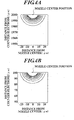
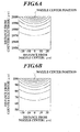
- a nozzle center position indicates a center position of a liquid jetting surface of a liquid jetting hole at a nozzle edge.
- FIG. 1A to FIG. 6A indicate electric field intensity distributions when a distance between a nozzle and a counter electrode is set to 2000[ ⁇ m]
- FIG. 1B to FIG. 6B indicate electric field intensity distributions when a distance between a nozzle and a counter electrode is set to 100[ ⁇ m].
- an applying voltage is set constant to 200[ V] in each condition.
- a distribution line in the drawings indicates a range of electric charge intensity from 1 x 10 6 [ V/m] to 1 x 10 7 [ V/m].
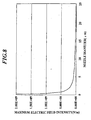
- FIG. 7 shows a chart indicating a maximum electric field under each condition.
- FIG. 1A to FIG. 6A and FIG. 1B to FIG. 6B the fact that an electric field intensity distribution spreads to a large area if the nozzle diameter is not less than ⁇ 20[ ⁇ m] (see FIG. 5A and FIG. 5B ), was comprehended. Further, according to the chart of FIG. 7 , the fact that a distance between a nozzle and a counter electrode has an influence on an electric field intensity was comprehended.
- FIG. 8 a relation between the nozzle diameter of a nozzle and a maximum electric field intensity when a liquid level is at an edge position of the nozzle is shown in FIG. 8 .
- Electric charge amount chargeable to a droplet is shown as the following equation (3), in consideration of Rayleigh fission (Rayleigh limit) of a droplet.
- q 8 ⁇ ⁇ ⁇ ⁇ 0 ⁇ ⁇ ⁇ d 0 3 8
- q electric charge amount [C] giving Rayleigh limit
- ⁇ 0 electric constant [F/m]
- ⁇ surface tension of the liquid solution [N/m]
- d 0 diameter [ m] of the droplet.
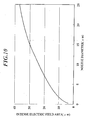
- FIG. 9 is a graph showing a relation among the nozzle diameter of the nozzle, a jetting start voltage at which a droplet jetted at a nozzle edge portion starts flying, a voltage value at Rayleigh limit of the initial jetted droplet, and a ratio of the jetting start voltage to the Rayleigh limit voltage.
- the nozzle diameter is set to more than ⁇ 0.2[ ⁇ m].
- a first embodiment will be described with reference to FIG. 11 to FIG. 21 .
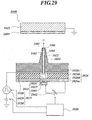
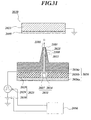
- An electrostatic sucking type droplet jetting apparatus as an embodiment to which the present invention is applied, as shown in FIG. 11 , comprises an electrostatic sucking type liquid jetting head 100 having first liquid room barriers 106, 106, ... and second liquid room barriers 107, 107, ..., as a convex meniscus forming section; a supplying pump for giving a supplying pressure of the liquid solution to each liquid solution supplying channel 101 of the liquid jetting head 100; and a circuit (jetting voltage applying section 25 and counter electrode 23 shown in FIG. 13 and FIG. 14 ) for driving the liquid jetting head 100.
- FIG. 11 is a perspective view showing a bottom surface of the liquid jetting head 100 as the embodiment to which the present invention is applied, with the bottom surface located at the front side of the paper and with a part thereof cut out.
- the liquid jetting head 100 comprises a liquid room structure 102 in which a plurality of liquid solution supplying channels are formed as liquid rooms, and a nozzle plate 104 having nozzles 103 being attached to a bottom portion of the liquid room structure 102, jetting chargeable liquid solution as a droplet from an edge portion thereof, having a super minute diameter and corresponding to the respective liquid solution supplying channels 101.
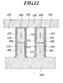
- FIG. 12 is a cross-sectional view mainly showing one liquid solution supplying channel 101 by seeing the liquid room structure 102 from its bottom surface direction.
- the liquid room structure 102 comprises a liquid room side wall 105, wherein a plurality of first liquid room barriers 106, 106, ... formed convexly with respect to the liquid room side wall 105 are placed in parallel with each other to the liquid room side wall 105.
- Second liquid room barriers 107 are respectively piled up on the first liquid room barriers 106, and the second liquid room barriers 107 adhere to and are fixed to the first liquid room barriers 106 via an adhesive layer 108.
- a plurality of grooves are formed by arranging a plurality of pairs of protrusions each of which comprises the first liquid room barrier 106 and the second liquid room barrier 107 in parallel with each other. Then, a cover plate 110 so adheres to and is fixed to the second liquid side walls 107, 107, ... via an adhesive layer 109 as to face the liquid room side wall 105 and to cover the plurality of grooves.
- a plurality of sectioned liquid solution supplying channels 101 are formed by a pair of 106 liquid room barrier 106, a pair of 107 liquid room barrier 107, the liquid room side wall 105 and the cover plate 110.
- each liquid solution supplying channel 101 is opened at a bottom surface of this liquid room structure 102, and each liquid solution supplying channel 101 is blocked by having a nozzle plate 104, which will be described later, adhere to and fixed to the bottom surface of the liquid room structure 102.
- a nozzle 103 is formed at the nozzle plate 104 in correspondence with each liquid solution supplying channel 101.
- Each liquid solution supplying channel 101 becomes shallow when being close to an upper edge surface 111 of the liquid room side wall 105, and a shallow groove 118 is formed in the vicinity of the upper edge surface 111.
- a liquid entrance opening 119 and a manifold 120 connected thereto are formed at an upper portion of the cover plate 110. Then, with each liquid solution supplying channel 101 covered with the cover plate 110, the upper edge portion of each liquid solution supplying channel 101 is connected to a liquid supplying source in which the liquid solution is stored, via the manifold 120 and the liquid entrance opening 119.
- This liquid jetting head 100 comprises a supplying pump (liquid solution supplying section) for giving a supplying pressure of the liquid solution to each liquid solution supplying channel 101, and the liquid supplying source supplies the liquid solution to each liquid solution supplying channel 101 by the pressure given by this supplying pump.
- This supplying pump supplies the liquid solution by maintaining a supplying pressure in a range within which the liquid solution does not spill out from an edge portion of the nozzle 103, which will be described later.
- a control electrode 121 is provided with the side walls of the liquid room barriers 106 and 107, and an insulating layer 125 is provided on the control electrode 121. Covering the control electrode 121 with the insulating layer 125 to make an internal wall of the liquid solution supplying channel 101 insulating prevents stroke from being generated through the liquid solution existing between a jetting electrode of the nozzle plate 104, which will be described later, and the control electrode 121.
- material and thickness of the insulating layer 125 it is necessary to determine them in consideration of conductivity of the liquid solution and an applying voltage.
- the insulating layer 125 one formed from parylene resin according to an evaporation method, and one formed from S i O 2 , S i3 N 4 according to a CVD method are suitable.
- a conduction pattern 123 corresponding to each liquid solution supplying channel 101 is formed, and the conduction pattern 123 and the control electrode 121 are connected by a conductor wire 124 according to a wire bonding method.
- the liquid room barriers 106 and 107 are piezoelectric ceramic plates, formed from piezoelectric ceramic material of lead zirconate titanates (PZT) having ferroelectricity, and dielectrically polarized in a laminating direction and in a direction opposing to each other.
- the liquid room barriers 106 and 107 change shapes by applying a voltage to the control electrode 121, and pressure is given to the liquid solution in the liquid solution supplying channel 101.
- a droplet is not jetted from the edge portion of the nozzle 103, which will be described later, and nothing but convex meniscus protruding to outside from the edge portion of the nozzle 103 is formed.
- these liquid room barriers 106, 106, ... and the liquid room barriers 107, 107, ... structure a convex meniscus forming section for forming a state where the liquid solution of each in-nozzle passage 145 rises in a convex form.
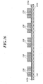
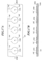
- FIG. 13 is a view showing a bottom surface of the nozzle plate 104
- FIG. 14 is a cross-sectional view taken along a cutting line XIV-XVI shown in FIG. 13 .
- the nozzle plate 104 comprises a base plate 141 as a base being electrically insulating; a plurality of jetting electrodes 142, 142, ... formed on a surface 141a of the base plate 141; and a nozzle layer 143 laminated over the whole surface 141a of the base plate 141 via the plurality of jetting electrodes 142, 142, ....
- a back surface 141b of the base plate 141 is fixed to the bottom surface of the above-mentioned liquid room structure 102 by adhesive or the like. Further, a plurality of through holes 141c, 141c, ... are formed at the base plate 141, and these through holes 141c, 141c, ... are so arranged as to correspond to the liquid solution supplying channels 101 respectively, to be communicated to the respective liquid solution supplying channels 101. In other words, the through holes 141c structure a lower portion of the liquid solution supplying channels 101.
- the jetting electrodes 142, 142, ... are so formed as to correspond to respective through holes 141c.
- Each jetting electrode 142 is formed on the surface 141a of the base plate so as to block the corresponding through hole 141c, and each jetting electrode 142 overlaps with the corresponding through hole 141c when being seen from the bottom surface.
- each jetting electrode 142 faces the corresponding liquid solution supplying channel 101, and structures the bottom surface of the corresponding liquid solution supplying channel 101.
- a through hole 142a is formed at the overlapping portion, and this through hole 142a is communicated to the corresponding liquid solution supplying channel 101.
- each jetting electrode 142 is connected to a bias power source 30, which will be described later.
- the jetting electrodes 142 have a ring shape and the wirings 144 have a rectangular shape, the present invention is not limited to such shapes.
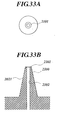
- a plurality of nozzles 103, 103, ... are integrally formed at the nozzle layer 143, and the plurality of nozzle 103, 103, ... are arranged in line.
- Each nozzle 103 is so formed as to stand (be suspended) perpendicularly with respect to the base plate 141.
- These nozzles 103, 103, ... are so arranged as to correspond to the liquid solution supplying channels 101 respectively, and each nozzle 103 overlaps with the corresponding through hole 141c when being seen from the bottom surface.
- An in-nozzle passage 145 penetrating from its edge portion along its center line is formed at each nozzle, and a jet opening 103a being an end of the in-nozzle passage 145 is formed at the edge portion of each nozzle 103.
- the in-nozzle passage 145 is communicated to the corresponding liquid solution supplying channel 101 through the through hole 142a of the jetting electrode 142, and the jetting electrode 142 faces the in-nozzle passage 145.
- the liquid solution supplied to each liquid solution supplying channel 101 is also supplied to the through hole 141c and in the in-nozzle passage 145, and is directly contacted to the jetting electrode 142 in each liquid solution supplying channel 101 and the in-nozzle passage 145.
- the plurality of nozzles 103, 103, ... are arranged in line. However, they may be arranged in two lines, or arranged in a matrix form.
- the nozzle layer 143 including these nozzles 103, 103, ... has electrical insulation properties, and an inside surface of the in-nozzle passage 145 also has electrical insulation properties. Further, the nozzle layer 143 including these nozzles 103, 103, ... may have water repellent properties (for example, the nozzle layer 143 is formed by resin having fluorine), or a water repellent layer having water repellent properties may be formed on a surface layer of the nozzles 103, 103, ... (for example, a metal layer is formed on the surface layer of the nozzles 103, 103, ..., and further on the metal layer, a water repellent layer by eutectoid plating between the metal and water repellent resin is formed).
- water repellent properties for example, the nozzle layer 143 is formed by resin having fluorine
- a water repellent layer having water repellent properties may be formed on a surface layer of the nozzles 103, 103, ... (for example, a metal layer is formed on the surface layer
- the water repellent properties are properties to repel the liquid solution jetted by the nozzle 103. Further, by selecting a water repellent processing method corresponding to liquid solution, it is possible to control water repellent properties of the nozzle layer 143.
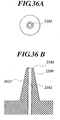
- an opening diameter at its edge portion and the in-nozzle passage 22 are constant, and as mentioned, these are formed as a super minute diameter.
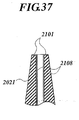
- a shape of the nozzle 103 is formed so that a diameter thereof is narrowed toward the edge portion, and is formed as a conic trapezoid shape being boundlessly close to a conic shape.
- an inside diameter of the in-nozzle passage 145 (that is, a diameter of the jet opening 103a) is not more than 30[ ⁇ m], further less than 20[ ⁇ m], further not more than 10[ ⁇ m], further not more than 8[ ⁇ m] and further not more than 4[ ⁇ m], and an inside diameter of the in-nozzle passage 145 is set to 1[ ⁇ m] in the present embodiment.
- an external diameter of the edge portion of the nozzle 103 is set to 2[ ⁇ m]
- a diameter of a root of the nozzle 103 is set to 5[ ⁇ m]
- a height of the nozzle 103 is set to 100[ ⁇ m].
- each dimension of the nozzle 103 is not limited to the above-mentioned one example.
- the nozzle inside diameter is in the range for realizing a jetting voltage being less than 1000[ V], the jetting voltage enabling droplet jetting by an effect of electric field concentration, which will be described later, for example, the nozzle diameter is not more than 70[ ⁇ m], more preferably, the diameter is not more than 20[ ⁇ m] and a diameter by which it is possible to realize the formation of a through hole for passing the liquid solution according to a current nozzle formation technology is set to its lower limit value.
- shapes of these nozzles 103, 103, ... are equal to each other, different shapes are allowable.
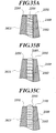
- a shape of the in-nozzle passage 145 may not be formed linearly with the inside diameter constant as shown in FIG. 14 .
- it may be so formed as to give roundness to a cross-section shape at the edge portion of the liquid solution supplying channel 101 side of the in-nozzle passage 145.
- an inside diameter at the edge portion of the liquid solution supplying channel 101 side of the in-nozzle passage 145 may be made larger than an inside diameter of the edge portion of the jetting side, and an inside surface of the in-nozzle passage 145 may be formed in a tapered circumferential surface shape.
- FIG. 15A it may be so formed as to give roundness to a cross-section shape at the edge portion of the liquid solution supplying channel 101 side of the in-nozzle passage 145.
- an inside diameter at the edge portion of the liquid solution supplying channel 101 side of the in-nozzle passage 145 may be made larger than an inside diameter of the edge portion of the jetting side, and an inside surface of the in-nozzle passage 145 may be formed in a tapered circumferential surface
- only the edge portion of the later-described liquid solution supplying channel 101 side of the in-nozzle passage 145 may be formed in a tapered circumferential surface shape and the jetting edge portion side with respect to the tapered circumferential surface may be formed linearly with the inside diameter constant.
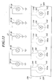
- This circuit for driving the liquid jetting head 100 comprises a jetting voltage applying section 25 (shown in FIG. 13 ) for applying a jetting voltage to each of the above-mentioned jetting electrodes 142, 142, ...; a facing surface 23a facing the above-mentioned nozzles 103, 103; ... and a counter electrode 23 (shown in FIG. 14 ) for supporting a base member 200 receiving a droplet at the facing surface 23a.
- the jetting voltage applying section 25 comprises a bias power source 30 for applying a bias voltage being direct current to the jetting electrode 142; and a jetting power source 29 for applying a pulse voltage to be superimposed to the bias voltage to have an electric potential necessary for jetting, to the jetting electrode 142, so as to correspond to each jetting electrode 142.
- the bias power source 30 and the jetting power source 29 may be in common for all of the jetting electrodes 142, 142, ..., and in this case, the jetting power source 29 applies the pulse voltage to these jetting electrodes 142, 142, ..., respectively.
- a bias voltage by the bias power source 30 by applying a voltage always within a range within which jetting of the liquid solution is not performed, width of a voltage applied at the time of jetting is preliminarily reduced, and thereby responsiveness at the time of jetting is improved.
- the jetting power source 29 superimposes a pulse voltage on a bias voltage only when the jetting of the liquid solution is performed and applies it to the jetting electrodes 142, 142, ... respectively.
- a value of the pulse voltage is set so that the superimposed voltage V at this time satisfies a condition of the following equation. h ⁇ ⁇ ⁇ 0 ⁇ d > V > ⁇ kd 2 ⁇ ⁇ 0
- ⁇ surface tension of the liquid solution [ N/m]
- ⁇ 0 electric constant [ F/m]
- d nozzle diameter [ m]
- h distance between nozzle and base member [m]
- k constant of proportionality dependent on nozzle shape (1.5 ⁇ k ⁇ 8.5).
- the bias voltage is applied at DC 300[ V]
- the pulse voltage is applied at 100[ V]. Therefore, the superimposed voltage at jetting will be 400[ V].
- the counter electrode 23 comprises a facing surface 23a being perpendicular to the nozzles 103, 103, ..., and supports the base member 200 along the facing surface 23a.
- a distance from an edge portion of the nozzles 103, 103, ... to the facing surface 23a of the counter electrode 23 is, set to 100[ ⁇ m] as one example.
- this counter electrode 23 since this counter electrode 23 is grounded, the counter electrode 23 always maintains a ground potential. Therefore, at the time of applying the pulse voltage, a jetted droplet is induced to the counter electrode 23 side by an electrostatic force according to an electric field generated between an edge portion of each nozzle 103 and the facing surface 23a.
- the liquid jetting head 100 jets a droplet by enhancing electric field intensity according tc electric field concentration at edge portions of the respective nozzles 103, 103, ... by miniaturization of the nozzles 103, 103, ..., it is possible to jet a droplet without the induction by the counter electrode 23.
- the induction by an electrostatic force is preferably performed between the nozzles 103, 103, ... and the counter electrode 23. Further, it is possible to let out the electric charge of a charged droplet by grounding the counter electrode 23.
- liquid solution as inorganic liquid, water, COCl 2 , HBr, HNO 3 , H 3 PO 4 , H 2 SO 4 , SOCl 2 , SO 2 CL 2 , FSO 2 H and the like can be cited.
- alcohols such as methanol, n-propanol, isopropanol, n-butanol, 2-methyl-1-propanol, tert-butanol, 4-metyl-2-pentanol, benzyl alcohol, ⁇ -terpineol, ethylene glycol, glycerin, diethylene glycol, triethylene glycol and the like; phenols such as phenol, o-cresol, m-cresol, p-cresol and the like; ethers such as dioxiane, furfural, ethyleneglycoldimethylether, methylcellosolve, ethylcellosolve, butylcellosolve, ethylcarbitol, buthylcarbitol, buthylcarbitolacetate, epichlorohydrin and the like; ketones such as acetone, ethyl methyl ketone, 2-methyl-4-pentanone, acetophenone and
- conductive paste which includes large amount of material having high electric conductivity (silver pigment or the like) is used, and in the case of performing the jetting, as objective material for being dissolved into or dispersed into the above-mentioned liquid, excluding coarse particles causing clogging to the nozzles, it is not in particular limited.
- fluorescent material such as PDP, CRT, FED or the like, what is conventionally known can be used without any specific limitation.
- red fluorescent material (Y,Gd)BO 3 :Eu, YO 3 :Eu and the like
- red fluorescent material Zn 2 SiO 4 :Mn, BaAl 12 O 19 :Mn, (Ba,Sr,Mg)O ⁇ -Al 2 O 3 :Mn and the like
- blue fluorescent material BaMgAl 14 O 23 :Eu, BaMgAl 10 O 17 :Eu and the like can be cited.
- binder for example, cellulose and its derivative such as ethyl cellulose, methyl cellulose, nitrocellulose, cellulose acetate, hydroxyethyl cellulose and the like; alkyd resin; (metha)acrylate resin and its metal salt such as polymethacrytacrylate, polymethylmethacrylate, 2-ethylhexylmethacrylate ⁇ methacrylic acid copolymer, lauryl methacrylate ⁇ 2-hydroxyethylmethacrylate copolymer and the like; poly(metha)acrylamide resin such as poly-N-isopropylacrylamide, poly-N,N-dimethylacrylamide and the like; styrene resins such as polystyrene, acrylonitrile ⁇ styrene copolymer, styrene ⁇ maleate copolymer, styrene ⁇ isoprene copolymer and the like; various saturated or unsaturated polyester resins; polyo
- the liquid jetting apparatus in the present embodiment is used as a patterning method, as a representative example, it is possible to use it for display use.
- the rib mentioned here means a barrier in general, and with plasma display taken as an example, it is used for separating plasma areas of each color.
- microlens for other uses, it is possible to apply it to microlens, patterning coating of magnetic material, ferrodielectric substance, conductive paste (wire, antenna) and the like for semiconductor use, as graphic use, normal printing, printing to special medium (film, fabric, steel plate), curved surface printing, lithographic plate of various printing plates, for processing use, coating of adhesive, sealer and the like using the present embodiment, for biotechnological, medical use, pharmaceuticals (such as one mixing a plurality of small amount of components), coating of sample for gene diagnosis or the like.
- the nozzle plate 104 is glued and fixed to the bottom surface of the liquid room structure 102.
- piezoelectric material made of titanate zirconate salts (PZT) which is to structure a liquid room side wall 105, a first liquid room barrier 106 and a second liquid room barrier 107 is prepared, and by using a doctor blade method, a screen printing method or the like, it is formed in a sheet-like shape having predetermined thickness.
- PZT titanate zirconate salts
- a piezoelectric laminating member is formed by laminating a pair of sheets with the use of adhesive which is to be an adhesive layer 108, and thereafter, a polarization processing is performed according to a known method, and thereby an upper-side sheet and a lower-side sheet are polarized in a direction of its thickness and in a direction in which they are opposed to each other.
- the above-mentioned piezoelectric laminating member structured by laminating the pair of sheets with a tool is ground, and thereby a plurality of groove portions that will structure the liquid solution supplying channel 101 are formed in parallel on the above-mentioned piezoelectric laminating member.
- an electrode is formed to the liquid room barriers 106 and 107 structuring the groove portions according to a known method such as plating or the like.
- a known method such as plating or the like.
- an electrode is not formed.
- adhesive which is to be the adhesive layer 109 is coated on an upper portion of the liquid room barrier 107 and the cover plate 110 is applied, the liquid room structure 102 structured with the plurality of liquid solution channels 101 formed in parallel with each other is produced.
- a driving base member 122 is attached to the liquid room side wall 105, and one end portion of the conductor wire 124 is connected to each electrode 11 and another end portion of the conductor wire 124 is connected to the conduction pattern 123.
- a base plate 141 having a flat plate shape is prepared (at this point, the plurality of through holes 141c have not been formed at the base plate 141.), a conductive coat 142b is formed over the whole surface of the surface 141a of the base plate 141 according to a coat-forming method such as a PVD method, a CVD method, a plating method or the like, and resists 150, 150, ... are formed on this conductive coat 142b according to a photolithography method.
- a shape of the resist 150 seen in a plane view is a shape combining the jetting electrode 142 and the wiring 144 seen in a bottom view.
- the base plate 141 may be a glass base plate, silicon wafer or a resin base plate, but has electrical isolation.
- the conductive coat 142b has its shape processed, and thereafter the resists 150, 150, ... are eliminated (refer to FIG. 17A and FIG. 17B ). Since the plurality of jetting electrodes 142, 142, ... are at once formed through the coating step, the mask step and the shape processing step in this way, productivity of the nozzle plate 104 is good.
- a resist layer (photosensitive resin layer) 1433 is formed over the whole surface 141a of the base plate 141 so as to cover all of these jetting electrodes 142, 142, ... and these wirings 144, 144, ... (see FIG. 18 ).
- This resist layer 143b may be a positive type or a negative type.
- the resist layer 143b is of photosensitive resin, and as its composition, PMMA, SU8 or the like is preferable.
- the resist layer 143 gets exposed by electron beam, femtosecond laser or the like according to the shape of the plurality of nozzles 103, 103, ... to be formed.
- the resist layer 143b is a positive type
- a part at the resist layer with which the through holes 142a of the jetting electrodes 142, 142, ... overlap is exposed down to a deep layer
- a part between the plurality of nozzles 103, 103, ... drown to a middle layer.
- the resist layer 143b is a negative type, a part at the resist layer 143 which is to become the plurality of nozzles 103, 103, ... is exposed.
- the resist layer 143b may not be exposed by electron beam or femtosecond laser, but be exposed by visible light, ultraviolet light, excimer laser, i-line, g-line or the like.
- electromagnetic radiation for the exposure may be one for exposing the resist layer 143b.
- the nozzle shape takes a conic shape or a truncated conic shape. However, it may take a flat shape without protrusion.
- the resist layer 143b is a positive type and of a photosensitive resin
- irradiation energy becomes larger when it is close to the surface side of the exposed resist layer 143b and conversely becomes smaller as it is closer to the base plate 141 side
- solubility to the developer becomes smaller as it is closer to the base plate 141 side. Therefore, in the case that the resist layer 143b is a positive type, it is possible to form the nozzles 103, 103, ... in approximately a conic shape or a truncated conic shape having a diameter becoming larger as it is close to the base plate 141 side, easily.
- the plurality of nozzles 103, 103, ... are at once formed by forming the coating over the resist layer 143b and thereafter by only exposing/developing the resist layer 143b, productivity of the liquid jetting head is good.
- a resist coating 151 is formed at the back surface 141b of the base plate 141 according to a photolithography method (refer to FIG. 20 ).
- a shape of the resist coating seen in a plane view is a shape having an opening at a part to become the through holes 141c, 141c, ....
- the resist coating 151 is eliminated (refer to FIG. 21 .). Thereby, the nozzle plate 104 is produced.
- the back surface 141b of the base plate is jointed to the bottom surface of the liquid room structure 102 (refer to FIG. 21 ). Further, the bias power source 30 and the jetting voltage power source 29 are electrically connected to each of the wirings 144, 144, ... Thereby, the liquid jetting head 100 is produced.
- a water repellent processing may be applied on the surface of the nozzles 103, 103, ....
- the surface of the nozzles 103, 103, ... may be so structured as to have water repellency by forming the resist layer 143 from a photosensitive resin having water repellency (for example, fluorine-containing photosensitive resin), or the surface of the nozzles 103, 103, ...
- a metal coat for example, Ni, Au, Pt or the like
- a water repellent coating formed according to eutectoid plating between its metal coating and a fluorine-containing resin after the nozzles 103, 103, ... are formed (the resist that masks the jet opening 103a is to be eliminated at last.).
- the photosensitive resin having water repellency is one in which from a few percent to a few dozen percent of Cytop, manufactured by Asahi Glass Co., Ltd, which is formed by fluororesin is dissolved into PTFE, FEP dispersion or perfluoro solvent having mean particle diameter of approximately 0.2 ⁇ m, is dispersed and mixed to an ultraviolet-sensitive resin, and in the dispersion, FEP having lower melting point is more preferably used.
- MDF FEP 120-J 54wt%, water-dispersion
- Fluon ⁇ AD911 60wt%, water-dispersion manufactured by Asahi Glass Co., Ltd, or the like is applicable.
- polymer for resist for F2-lithography is also a fluorine-containing photosensitive resin, such as one in which fluorine is induced to polymer main chain, and one in which fluorine is induced to side chain.
- the nozzles 103, 103, ... are formed by only exposing and developing the resist layer 143b, it is advantageous in view of flexibility to a shape of the nozzle 103, production cost, and correspondence to a long-length line head.
- a silicon base plate is based and minute holes are formed on the silicon base plate, it is considered that, flexibly changing a shape of the nozzle is more convenient in the producing method in the present embodiment, producing a long-length line head is also advantageous in the producing method in the present embodiment, and production cost of the head 100 is also advantageous in the present embodiment.
- FIG. 22A is a graph showing a relation between time (horizontal axis) and a voltage applied to liquid solution (vertical axis) in a case of not jetting
- FIG. 22B is a cross-sectional view showing a state of a nozzle 103 in the case of not jetting
- FIG. 22C is a graph showing a relation between time (horizontal axis) and a voltage applied to the liquid solution (vertical axis) in a case of jetting
- FIG. 22D is a cross-sectional view showing a state of the nozzle 103 in the case of jetting.
- the jetting voltage power source 29 applies the pulse voltage to the liquid solution via the jetting electrode 142, and the pulse voltage is also applied to the control electrode 121 in synchronization with this pulse voltage (refer to FIG. 22C .).
- the pulse voltage is applied to the control electrode 121, the liquid room barriers 106 and 107 swell and capacity of the liquid solution supplying channel 101 is reduced, and thereby a pressure of the liquid solution in the liquid solution supplying channel 101 increases. Accordingly, meniscus in a convex form protruding to outside is formed at the edge portion of the nozzle 103.
- the pulse voltage is applied to the jetting electrode 142 approximately at the same time that the pulse voltage is applied to the control electrode 121, an electric field is concentrated at the top of the meniscus in a convex form protruding to outside, and after all a minute droplet is jetted to the counter electrode side against a surface tension of the liquid solution (refer to FIG. 22D ).
- the pulse voltage applied to the jetting electrode 142 is finished and the pulse voltage applied to the control electrode 121 is finished, the meniscus which dents in a convex form in the liquid solution is formed at the edge portion of the nozzle 103 by increasing the capacity of the liquid solution supplying channel 101, and the liquid solution is supplied to the in-nozzle passage 145 of the nozzle 103 that jetted the liquid through the liquid entrance opening 119 and the manifold 120.
- the liquid room barriers 106 and 107 swell and the capacity of the liquid solution supplying channel 101 increases with the pulse voltage applied to the control electrode 121.
- the capacity of the liquid solution supplying channel 101 may be reduced by shrinking the liquid room barriers 106 and 107 with the pulse voltage applied to the control electrode 121.
- the pulse voltage is not applied to the control electrode 121, and at the time of not jetting, when the bias voltage is applied to the jetting electrode 142, the pulse voltage is applied to the control electrode 121.
- a non-jetting voltage V 0 is applied to the jetting electrode 142 when a meniscus position is lower than the edge of the nozzle 103, and by applying the pulse voltage to the control electrode 121, the capacity of the liquid solution supplying channel 101 is changed, and thereby the jetting can be controlled by controlling a meniscus position jetted from the edge of the nozzle 103 being capable of jetting at the voltage V 0 .
- meniscus in a convex form is formed by giving a pressure to the liquid solution in the liquid solution supplying channel 101 through the liquid room barriers 106 and 107 being piezoelectric elements, at the time of jetting.
- meniscus in a convex form may be formed by giving a pressure to the liquid solution by the film boiling cf the liquid solution in the liquid solution supplying channel 101 with a heater or the like. Since convex meniscus forming section is to change the pressure of the liquid solution in the in-nozzle passage 145, the section may be a method of changing the capacity of the liquid solution supplying channel 101, and an electrostatic sucking method for changing the capacity by bending the wall of the liquid solution supplying channel 101 with an electrostatic force is possible.
- jetting may be done without forming meniscus in a convex form
- a case of jetting with forming meniscus in a convex form is advantageous in view of making the jetting voltage constant, safety at the droplet jetting control, and control cost.
- the above-mentioned liquid jetting head 100 As a method of using the above-mentioned liquid jetting head 100, for example, while the above-mentioned liquid jetting head 100 (mainly, the liquid room structure 102 and the nozzle plate 104) is moved within a plane parallel to the base member 200, relatively with respect to the base member 200, a droplet is selectively jetted from the edge portion of each nozzle 103, and thereby a pattern where droplets dropped at the surface of the base member 200 become dots is formed on the surface of the base member 200. Further, since the plurality of nozzles 103, 103, ... are arranged in line, by moving the base member 200 in a direction being perpendicular with respect to the line of the nozzles 103, 103, ...
- the liquid jetting head 100 comprises the plurality of nozzles 103, 103, ..., it is possible to form the pattern quickly.
- liquid jetting head 100 for any one of: formation of a wiring pattern of a circuit; formation of a wiring pattern of a metal super fine particle; formation of carbon nanotube, its precursor and catalytic arrangement; formation of patterning of ferroelectric ceramics and its precursor; high-orientation of high polymer molecule and its precursor; zonerefining; microbeads manipulation; active tapping; and formation of spacial configuration.
- the above-mentioned liquid jetting head 100 jets a droplet by the nozzle 103 having a minute diameter, which cannot be found conventionally, an electric field is concentrated by the liquid solution being in a charged state in the in-nozzle passage 145, and thereby electric field intensity is enhanced. Therefore, jetting of the liquid solution by a nozzle having a minute diameter (for example, inside diameter 100[ ⁇ m] ), which was conventionally regarded as substantially impossible since a voltage necessary for jetting would become too high with a nozzle having a structure in which concentration of an electric field is not performed, is now possible with a lower voltage than the conventional one.
- a minute diameter for example, inside diameter 100[ ⁇ m]
- the jetted droplet is charged, even though it is a minute droplet, a vapor pressure is reduced and evaporation is suppressed, and thereby the loss of mass of the droplet is reduced, the flying stabilization is achieved and the decrease of landing accuracy of the droplet is prevented.
- the surface of the nozzles 103, 103, ... has water repellency, at the time that the liquid solution should not be jetted, the liquid solution in the nozzles 103, 103, ... does not drip nor flow. Further, since the surface of the nozzles 103, 103, ... has water repellency, an adverse effect is not caused to the jetting of a droplet with the liquid solution adhering to the periphery of the jet opening 103a. Further, since the surface of the nozzles 103, 103, ... has water repellency, the meniscus formed at the time of jetting is formed in a refined convex shape, and thereby a droplet is stably jetted.
- an electrode for example, the metal coating formed under the above-mentioned water repellent coating.
- an electrode may be provided at a circumference of the nozzle 103, or an electrode may be provided at an inside surface of the in-nozzle passage 145 and a dielectric coating covers thereover. Then, by applying a voltage to this electrode, it is possible to enhance wettability of the inside surface of the in-nozzle passage 145 with respect to the liquid solution to which the voltage is applied by the jetting electrode 142 according to the electrowetting effect, and thereby it is possible to suitably perform the jetting and improve the responsiveness of the jetting.
- the jetting voltage applying section 25 always applies the bias voltage to each jetting electrode 142 for jetting a droplet by using the pulse voltage as a trigger.
- the jetting is performed by always applying alternate current having an amplitude necessary for jetting or a continuous rectangular wave to each jetting electrode 142 and by changing high and low of its frequency. It is essential to have the liquid solution charged for jetting a droplet, and when the jetting voltage is applied at a frequency exceeding a speed at which the liquid solution is charged, the jetting is not performed, but the jetting is performed when it is switched to a frequency at which it is possible to charge the liquid solution sufficiently.
- a second unclaimed embodiment will be described with reference to FIG. 23 to FIG. 28 .
- FIG. 23 is a view showing a whole structure of a liquid jetting apparatus 1020 in the second embodiment to which the liquid jetting apparatus is applied.
- the apparatus is shown with a part thereof cut out along a nozzle 1021.
- the whole structure of the liquid jetting apparatus 1020 will he described with reference to FIG. 23 .
- This liquid jetting apparatus 1020 comprises the nozzle 1021 having a super minute diameter for jetting a droplet of chargeable liquid solution from its edge portion; a counter electrode 1023 having a facing surface facing the edge portion of the nozzle 1021 and supporting a base member 1099 for receiving the landing of the droplet; a liquid solution supplying section 1031 for supplying the liquid solution to a passage 1022 in the nozzle 1021; a jetting voltage applying section 1025 for applying a jetting voltage to the liquid solution in the nozzle 1021; and an operation control section 1050 for controlling the applying of the jetting voltage by the jetting voltage applying section 1025.
- the above-mentioned nozzle 1021, a partial structure of the liquid solution supplying section 1031 and a partial structure of the jetting voltage applying section 1025 are integrally formed by a nozzle plate 1026.
- FIG. 23 for the convenience of a description, a state where the edge portion of the nozzle 1021 faces upward and the counter electrode 1023 is provided above the nozzle 1021, is illustrated.
- the apparatus is so used that the nozzle 1021 faces in a horizontal direction or a lower direction than the horizontal direction, more preferably, the nozzle 1021 faces perpendicularly downward.
- liquid solution jetted by the above-mentioned liquid jetting apparatus 1020 as inorganic liquid, water, COCl 2 , HBr, HNO 3 , H 3 PO 4 , H 2 SO 4 , SOCl 2 , SO 2 CL 2 , FSO 2 H and the like can be cited.
- alcohols such as methanol, n-propanol, isopropanol, n-butanol, 2-methyl-1-propanol, tert-butanol, 4-metyl-2-pentanol, benzyl alcohol, ⁇ -terpineol, ethylene glycol, glycerin, diethylene glycol, triethylene glycol and the like; phenols such as phenol, o-cresol, m-cresol, p-cresol and the like; ethers such as dioxiane, furfural, ethyleneglycoldimethylether, methylcellosolve, ethylcellosolve, butylcellosolve, ethylcarbitol, buthylcarbitol, buthylcarbitolacetate, epichlorohydrin and the like; ketones such as acetone, ethyl methyl ketone, 2-methyl-4-pentanone, acetophenone and
- conductive paste which includes large amount of material having high electric conductivity (silver pigment or the like) is used, and in the case of performing the jetting, as objective material for being dissolved into or dispersed into the above-mentioned liquid, excluding coarse particles causing clogging to the nozzles, it is not in particular limited.
- fluorescent material such as PDP, CRT, FED or the like, what is conventionally known can be used without any specific limitation.
- red fluorescent material (Y,Gd)BO 3 :Eu, YO 3 :Eu and the like
- red fluorescent material Zn 2 SiO 4 :Mn, BaAl 12 O 19 :Mn, (Ba,Sr,Mg)O ⁇ -Al 2 O 3 :Mn and the like
- blue fluorescent material BaMgAl 14 O 23 :Eu, BaMgAl 10 O 17 :Eu and the like can be cited.
- binder for example, cellulose and its derivative such as ethyl cellulose, methyl cellulose, nitrocellulose, cellulose acetate, hydroxyethyl cellulose and the like; alkyd resin; (metha)acrylate resin and its metal salt such as polymethacrytacrylate, polymethylmethacrylate, 2-ethylhexylmethacrylate ⁇ methacrylic acid copolymer, lauryl methacrylate ⁇ 2-hydroxyethylmethacrylate copolymer and the like; poly(metha)acrylamide resin such as poly-N-isopropylacrylamide, poly-N,N-dimethylacrylamide and the like; styrene resins such as polystyrene, acrylonitrile ⁇ styrene copolymer, styrene ⁇ maleate copolymer, styrene ⁇ isoprene copolymer and the like; various saturated or unsaturated polyester resins; polyo
- the liquid jetting apparatus 1020 When the liquid jetting apparatus 1020 is used as a patterning method, as a representative example, it is possible to use it for display use. Concretely, it is possible to cite formation of fluorescent material of plasma display, formation of rib of plasma display, formation of electrode of plasma display, formation of fluorescent material of CRT, formation of fluorescent material of FED (Field Emission type Display), formation of rib of FED, color filter for liquid crystal display (RGB coloring layer, black matrix layer), spacer for liquid crystal display (pattern corresponding to black matrix, dot pattern and the like).
- the rib mentioned here means a barrier in general, and with plasma display taken as an example, it is used for separating plasma areas of each color.
- microlens for other uses, it is possible to apply it to microlens, patterning coating of magnetic material, ferrodielectric substance, conductive paste (wire, antenna) and the like for semiconductor use, as graphic use, normal printing, printing to special medium (film; fabric, steel plate), curved surface printing, lithographic plate of various printing plates, for processing use, coating of adhesive, sealer and the like using the present embodiment, for biotechnological, medical use, pharmaceuticals (such as one mixing a plurality of small amount of components), coating of sample for gene diagnosis or the like.
- the above-mentioned nozzle 1021 is integrally formed with an upper surface layer 1026c of the nozzle plate 1026, which will be described later, and is provided to stand up perpendicularly with respect to a flat plate surface of the nozzle plate 1026. Further, at the time of jetting a droplet, the nozzle 1021 is used to perpendicularly face a receiving surface (surface where the droplet lands) of the base member 1099. Further, in the nozzle 1021, an in-nozzle passage 1022 penetrating from an edge portion of the nozzle 1021 along the nozzle center is formed.
- the in-nozzle passage 1022 is opened at an edge of the nozzle 1021, and thereby a jet opening to be an end of the in-nozzle passage 1022 is formed at the edge of the nozzle 1021.
- a diameter of the jet opening formed at the nozzle 1021 (that is, inside diameter of the nozzle 1021) is not more than 30 ⁇ m, more preferably less than 20 ⁇ m, even more preferably not more than 10 ⁇ m, even more preferably not more than 8 ⁇ m, even more preferably not more than 4 ⁇ m.
- an opening diameter of its edge portion and the in-nozzle passage 1022 are uniform, and as mentioned, these are so formed as to have a super minute diameter.
- an inside diameter of the in-nozzle passage 1022 is set to 1[ ⁇ m]
- an outside diameter of the edge portion of the nozzle 1021 is set to 2[ ⁇ m]
- a diameter of the root of the nozzle 1021 is 5[ ⁇ m]
- a height of the nozzle 1021 is set to 100[ ⁇ m]
- a shape thereof is formed as a truncated conic shape being unlimitedly close to a conic shape.
- the height of the nozzle 1021 may be 0[ ⁇ m].
- a shape of the in-nozzle passage 1022 may not be' formed linearly with having a constant inside diameter as shown in FIG. 23 .
- it may be so formed as to give roundness to a cross-section shape at the edge portion of the side of a liquid solution room 1024, which will be described later, of the in-nozzle passage 1022.
- an inside diameter at the edge portion of the side of the liquid solution room 1024, which will be described later, of the in-nozzle passage 1022 may be set to be larger than an inside diameter of the edge portion of the jetting side, and an inside surface of the in-nozzle passage 1022 may be formed in a tapered circumferential surface shape.
- FIG. 15A it may be so formed as to give roundness to a cross-section shape at the edge portion of the side of a liquid solution room 1024, which will be described later, of the in-nozzle passage 1022.
- an inside diameter at the edge portion of the side of the liquid solution room 1024, which will be described later, of the in-nozzle passage 1022 may be set
- edge portion of the side of the liquid solution room 1024, which will be describe later, of the in-nozzle passage 1022 may be formed in a tapered circumferential surface shape and the jetting edge portion side with respect to the tapered circumferential surface may be formed linearly with constant inside diameter.
- the liquid supplying section 1031 is provided at a position being inside of the nozzle plate 1026 and at the root of the nozzle 1021, and comprises the liquid solution room 1024 communicated to the in-nozzle passage 1022; a supplying passage 1027 for guiding the liquid solution from an external liquid solution tank, of which illustration is omitted, to the liquid solution room 1024; and a supplying pump for giving a supplying pressure of the liquid solution to the liquid solution room 1024.
- the above-mentioned supplying pump supplies the liquid solution to the edge portion of the nozzle 1021, and supplies the liquid solution while maintaining the supplying pressure within a range within which the liquid solution is not dripped (refer to FIG. 24A and FIG. 24B .).
- this supplying pump may be one using a pressure difference according to arrangement positions of the liquid solution tank and the nozzle 1021.
- the liquid solution supplying section 1031 may, as described in a third embodiment, comprise a mechanism for changing capacity of the liquid solution room 1024 and for controlling the supplying pressure of the liquid solution (refer to FIG. 29 .).
- this mechanism which controls the supplying pressure of the liquid solution one changing a voltage and changing a shape of a liquid solution room wall such as a piezoelectric element, one changing capacity of the liquid solution room with air bubble by using a heater, or one changing the liquid solution room wall with an electrostatic force, is applicable.
- the jetting voltage applying section 1025 comprises a jetting electrode 1028 for applying a jetting voltage, the jetting electrode 1028 being provided inside of the nozzle plate 1026 and at a border position between the liquid solution room 1024 and the in-nozzle passage 1022; a bias power source 1030 for always applying a direct current bias voltage to this jetting electrode 1028; and a jetting voltage power source 1029 for applying a pulse voltage to the jetting electrode 1028 by superimposing the bias voltage thereto, to be an electric potential for the jetting.
- the above-mentioned jetting electrode 1028 is directly contacted to the liquid solution in the liquid solution room 1024, for charging the liquid solution and applying the jetting voltage.
- the bias voltage by the bias power source 1030 by always applying the voltage within a. range within which the jetting of the liquid solution is not performed, a width of a voltage to be applied at the jetting is preliminarily reduced, herewith responsiveness at the jetting is improved.
- the jetting voltage power source 1029 is controlled by the operation control section 1050, to superimpose the pulse voltage to the bias voltage to be applied only when the jetting of the liquid solution is performed.
- a value of the pulse voltage is set so that a superimposed voltage V at this time should satisfy a condition of the following equation (1).
- y surface tension of liquid solution [ N/m]
- ⁇ 0 electric constant [ F/m]
- d nozzle diameter [m]
- h distance between nozzle and base member [m]
- k constant of proportionality dependent on nozzle shape (1.5 ⁇ k ⁇ 8.5).
- the bias voltage is applied at DC300[ V]
- the pulse voltage is applied at 100[ V]. Therefore, the superimposed voltage at jetting will be 400[ V].
- the nozzle plate 1026 comprises a base layer 1026a placed at the lowest layer in FIG. 23 ; a passage layer 1026b placed on top of it, the passage layer 1026b forming a supplying passage of the liquid solution; and an upper surface layer 1026c formed further on top of this passage layer 1026b.
- the above-mentioned jetting electrode 1028 is inserted between the passage layer 1026b and the upper surface layer 1026c.
- the above-mentioned base layer 1026a is formed from a silicon base plate, highly-insulating resin or ceramic, and a dissolvable resin layer is formed on top thereof and it is eliminated except for a part corresponding to a predetermined pattern for forming the supplying passage 1027 and the liquid solution room 1024, and the insulating resin layer is formed at the eliminated part.
- This insulating resin layer becomes the passage layer 1026b.
- the jetting electrode 1028 is formed on an upper surface of this insulating resin layer by an electroless plating of a conductive element (for example NiP), and a resist resin layer having insulating properties is formed further on top thereof.
- a conductive element for example NiP
- this resist resin layer becomes the upper surface layer 1026c, this resin layer is formed with a thickness in consideration of a height of the nozzle 1021. Then, this insulating resist resin layer is exposed according to an electron beam method or femtosecond laser, for forming a nozzle shape.
- the in-nozzle passage 1022 is also formed according to a laser processing. Then, the dissolvable resin layer corresponding to the pattern of the supplying passage 1027 and the liquid solution room 1024 is eliminated, these supplying passage 1027 and the liquid solution room 1024 are communicated to each other, and the production of the nozzle plate 1026 is completed.
- material of the upper surface layer 1026c and the nozzle 1021 may be, concretely, semiconductor such as Si or the like, conductive material such as Ni, SUS or the like, other than insulating material such as epoxy, PMMA, phenol, soda glass.
- FIG. 25 is a vertical cross-sectional view of the nozzle 1021. As shown in FIG. 25 , a water repellent coating 1101 is formed at a surface of the circumference of a jet opening of the nozzle 1021, and a water repellent coating 1102 is formed at an inside surface of the nozzle 1021.
- PTFE particles may be made eutectoid into a plating coat for forming the water repellent coating, or Product name Cytop (registered mark) manufactured by Asahi Glass Co., Ltd., or the like may be coated for forming the water repellent coating.
- electrocoating of cationic or anionic fluorine-containing resin coating of fluorinated high polymer, silicon resins and polydimethylsiloxane; sintering; eutectoid plating method of fluorinated high polymer; evaporation method of amorphous alloy membrane; making a coat such as organic silicon compound, fluorine-containing silicon compound or the like centering on polydimethylsiloxanes formed by plasma-polymerizing hexamethylsiloxiane as monomer according to a plasma CVD method, are available. Control of water repellency of the nozzle can be managed by selecting a processing method corresponding to liquid solution.
- the fluorine-containing photosensitive resin is one in which from a few percent to a few dozen percent of Cytop, manufactured by Asahi Glass Co., Ltd, which is formed by fluororesin is dissolved into PTFE dispersion, FEP dispersion or perfluoro solvent having a mean particle diameter of approximately 0.2 ⁇ m, is dispersed and mixed to ultraviolet-sensitive resin, and in the dispersion, FEP having a lower melting point is preferably used.
- MDF FEP 120-J 54wt%, water-dispersion
- Fluon ⁇ AD911 60wt%, water-dispersion
- Asahi Glass Co., Ltd or the like
- polymer for resist for F2-lithography is also fluorine-containing photosensitive resin, such as one in which fluorine is induced to polymer main chain, and one in which fluorine is induced to side chain.
- the counter electrode 1023 comprises a facing surface being perpendicular to a protruding direction of the nozzle 1021, and supports the base member 1099 along the facing surface.
- a distance from the edge portion of the nozzle 1021 to the facing surface of the counter electrode 1023 is, as one example, set to 100[ ⁇ m].
- this counter electrode 1023 since this counter electrode 1023 is grounded, the counter electrode 1023 always maintains a grounded electric potential. Therefore, at the time of applying the pulse voltage, a droplet jetted according to an electrostatic force by an electric field generated between the edge portion of the nozzle 1021 and the facing surface is guided to a side of the counter electrode 1023.
- the liquid jetting apparatus 1020 jets a droplet by enhancing electric field intensity according to electric field concentration at the edge portion of the nozzle 1021 according to super-miniaturization of the nozzle 1021, it is possible to jet the droplet without the guiding by the counter electrode 1023.
- the guiding by an electrostatic force between the nozzle 1021 and the counter electrode 1023 is preferably performed. Further, it is possible to let out the electric charge of a charged droplet by grounding the counter electrode 1023.
- the operation control section 1050 is in practice structured from a calculation device including a CPU, a ROM, a RAM and the like.
- the above-mentioned operation control section 1050 makes the bias power source 1030 apply a voltage continuously, and makes the jetting voltage power source 1029 apply a driving pulse voltage when receiving an input of a jetting instruction from outside.
- FIG. 24A is a graph showing a relation between time (horizontal axis) and a voltage applied to the liquid solution (vertical axis) in a case of not jetting
- FIG. 24B is a vertical cross-sectional view showing a state of the nozzle 1021 in the case of not jetting
- FIG. 24C is a graph showing a relation between time (horizontal axis) and a voltage applied to the liquid solution (vertical axis) in a case of jetting
- FIG. 24D is a vertical cross-sectional view showing a state of the nozzle 1021 in the case of jetting.
- a jetting instruction signal is inputted to the operation control section 1050, and when the jetting voltage power source 1029 applies the pulse voltage (refer to FIG. 24C .), the liquid solution is guided to the edge portion side of the nozzle 1021 by an electrostatic force according to electric field intensity of a concentrated electric field at the edge portion of the nozzle 1021, and a convex meniscus protruding to outside is formed, and an electric field is concentrated at the top of the convex meniscus, and after all a minute droplet is jetted to the counter electrode side against a surface tension of the liquid solution (refer to FIG. 24D ).
- the liquid jetting apparatus 1020 performs jetting of a droplet by the nozzle 1021 having a minute diameter, which was not available conventionally, an electric field is concentrated by the liquid solution in a state of being charged in the in-nozzle passage 1022, and thereby electric field intensity is enhanced. Accordingly, the jetting of the liquid solution by a nozzle having a minute diameter (for example, an inside diameter of 100[ ⁇ m], which was conventionally regarded as substantially impossible since a voltage necessary for jetting would become too high with a nozzle having a structure with which concentration of an electric field is not performed, is now possible with a lower voltage than the conventional one.
- a minute diameter for example, an inside diameter of 100[ ⁇ m]
- FIG. 26 shows a voltage applying pattern when the liquid jetting apparatus 1020 in the present embodiment is on standby for jetting.
- the standby for jetting is a time for preparing the next jetting while the liquid jetting apparatus 1020 is functioning.
- the vertical axis indicates an applied voltage V and the horizontal axis indicates course of time t.
- voltages Va and Vb which are different from each other and smaller than the jetting start voltage V C are alternately applied.
- the voltage applying pattern may be a pulse wave as shown in FIG. 26 , or a sine wave.
- FIG. 28 is a diagram showing an experimental condition and an experimental result of an experiment example using the liquid jetting apparatus 1020 in the present embodiment. As shown in FIG. 28 , cases are divided into: one in which a water repellent coating is not formed to the nozzle; one in which the water repellent coating 1101 is formed on the surface of the circumference of a jet opening of the nozzle (water repellent coating area 1), the water repellent coatings 1101 and 1102 are formed on the surface of the circumference of the jet opening of the nozzle and the inside surface of the nozzle (water repellent coating area 2); one in which the voltage shown in FIG. 26 is not applied while it is on standby for jetting; and one that the voltage is applied. Under conditions 1 to 6, an experiment regarding responsiveness and clogging is performed.
- FIG. 27 shows a test driving pattern.
- the horizontal axis indicates time.
- responsiveness can be an index that indicates a degree of clogging. From the result of the present experiment, it is possible to say that, for preventing clogging of the nozzle, it is effective to form a water repellent coating at the nozzle, and to apply a varying voltage being smaller than the jetting start voltage V C , to the liquid solution in the nozzle while on standby for jetting.
- liquid jetting apparatus 1020 in the second embodiment since, by vibrating a liquid level in the nozzle while it is on standby, and by stirring charged components in the liquid solution, it is possible to maintain a state where the charged components in the liquid solution are evenly dispersed, it is possible to suppress the charged components from being aggregated. Further, since it is possible to always move the liquid solution, it is possible to suppress the liquid solution from adhering in the nozzle, to prevent the liquid solution from being fixed to the nozzle 1021, and prevent clogging of the nozzle 1021.
- the liquid solution does not easily adhere to the nozzle 1021 and the liquid solution is not easily fixed to the nozzle 1021, it is possible to prevent clogging of the nozzle 1021.
- FIG. 29 A third unclaimed embodiment will be described with reference to FIG. 29 , FIG. 30A, FIG. 30B and FIG. 30C .
- FIG. 29 is a view showing a whole structure of a liquid jetting apparatus 1040 in the third embodiment to which the liquid jetting apparatus is applied.
- a part of the liquid jetting apparatus 1040 is cut out along the nozzle 1021 to be shown.
- FIG. 30A is a view showing a state where liquid solution in an in-nozzle passage forms meniscus in a reentrant shape at an edge portion of the nozzle 1021.
- FIG. 30B is a view showing a state where the liquid solution in the in-nozzle passage 1022 forms meniscus in a convex shape at the edge portion of the nozzle 1021.
- FIG. 30C is a view showing a state where a liquid level of the liquid solution in the in-nozzle passage 1022 is drawn into as much as a predetermined distance.
- FIG. 29 As shown in FIG. 29 , FIG. 30A, FIG. 30B and FIG. 30C , in the liquid jetting apparatus 1040, an identical mark is added to a portion being identical to any portion of the liquid jetting apparatus 1020 in the second embodiment, and descriptions regarding the identical portion are omitted.
- a base layer 1026a located at the lowest layer of the nozzle plate 1026 is formed of a metal plate, and a highly-insulating resin is formed as a coating over the whole upper surface of this base layer 1026a, for forming an insulating layer 1026b.
- the driving voltage power source 1042 outputs a driving voltage corresponding to a voltage value suitable for the piezo element 1041 to decrease the capacity of the liquid solution room 1024 so as to transfer from a state where the liquid solution in the in-nozzle passage 1022 forms meniscus in a reentrant shape (refer to FIG. 30A .) to a state where meniscus in a convex shape is formed (refer to FIG. 30B .).
- the driving voltage power source 1042 outputs a voltage corresponding to a voltage value suitable for the piezo element 1041 to increase the capacity of the liquid solution room 1024 so as to transfer from a state where the liquid solution in the in-nozzle passage 1022 forms meniscus in a reentrant shape at the edge portion of the nozzle 1021 (refer to FIG. 30A .) to a state where the liquid level is drawn into as much as a predetermined distance (refer to FIG. 30C ).
- a predetermined voltage to the piezo element 1041 and by making the base layer 1026a dent in either inside or outside at a position of FIG.
- a predetermined voltage is applied to the piezo element 1041, and as shown in FIG. 30A and FIG. 30B , control is done so as to place the liquid level of the liquid solution within the nozzle.
- a supplying pressure of the liquid solution may be controlled by the supplying pump of the liquid solution supplying section 1031 so as to locate the liquid level in the nozzle.
- liquid jetting apparatus 1040 in the third embodiment since the liquid level is within the nozzle, it is possible to prevent the liquid solution from adhering to the circumference of the nozzle 1021. Further, it is possible to prevent the liquid solution from being dried, and thereby it is possible to prevent the liquid solution from being fixed to the nozzle 1021. Therefore, it is possible to prevent clogging of the nozzle 1021.
- a fourth unclaimed embodiment will be described with reference to FIG. 31 to FIG. 36 .
- FIG. 31 is a view showing a whole structure of a liquid jetting apparatus 2020 in the fourth embodiment to which the liquid jetting apparatus is applied.
- a part of the liquid jetting apparatus 2020 is cut out along a nozzle 2021 to be shown.
- the whole structure of the liquid jetting apparatus 3020 will be described with reference to FIG. 31 .
- This liquid jetting apparatus 2020 comprises the nozzle 2021 being a super minute diameter for jetting a droplet of chargeable liquid solution from its edge portion; a counter electrode 2023 having a facing surface facing to the edge portion cf the nozzle 2021 and supporting a base member 2099 for receiving landing of the droplet at the facing surface; a liquid solution supplying section 2031 for supplying the liquid solution to a passage 2022 in the nozzle 2021; a jetting voltage applying section 2025 for applying a jetting voltage to the liquid solution in the nozzle 2021; and an operation control section 2050 for controlling the applying of the jetting voltage by the jetting voltage applying section 2025.
- the above-mentioned nozzle 2021, a partial structure of the liquid solution supplying section 2031 and a partial structure of the jetting voltage applying section 2025 are integrally formed by a nozzle plate 2026.
- the apparatus is so structured that the nozzle 2021 faces in a horizontal direction or a lower direction than the horizontal direction, more preferably, the nozzle 2021 faces perpendicularly downward.
- liquid solution jetted by the above-mentioned liquid jetting apparatus 2020 as inorganic liquid, water, COCl 2 , HBr, HNO 3 , H 3 PO 4 , H 2 SO 4 , SOCl 2 , SO 2 CL 2 , FSO 2 H and the like can be cited.
- alcohols such as methanol, n-propanol, isopropanol, n-butanol, 2-methyl-1-propanol, tert-butanol, 4-metyl-2-pentanol, benzyl alcohol, ⁇ -terpineol, ethylene glycol, glycerin, diethylene glycol, triethylene glycol and the like; phenols such as phenol, o-cresol, m-cresol, p-cresol and the like; ethers such as dioxiane, furfural, ethyleneglycoldimethylether, methylcellosolve, ethylcellosolve, butylcellosolve, ethylcarbitol, buthylcarbitol, buthylcarbitolacetate, epichlorohydrin and the like; ketones such as acetone, ethyl methyl ketone, 2-methyl-4-pentanone, acetophenone and
- conductive paste which includes large amount of material having high electric conductivity (silver pigment or the like) is used, and in the case of performing the jetting, as objective material for being dissolved into or dispersed into the above-mentioned liquid, excluding coarse particles causing clogging to the nozzles, it is not in particular limited.
- fluorescent material such as PDP, CRT, FED or the like, what is conventionally known can be used without any specific limitation.
- red fluorescent material (Y,Gd)BO 3 :Eu, YO 3 :Eu and the like
- red fluorescent material Zn 2 SiO 4 :Mn, BaAl 12 O 19 :Mn, (Ba,Sr,Mg)O ⁇ -Al 2 O 3 :Mn and the like
- blue fluorescent material BaMgAl 14 O 23 :Eu, BaMgAl 10 O 17 :Eu and the like can be cited.
- binder for example, cellulose and its derivative such as ethyl cellulose, methyl cellulose, nitrocellulose, cellulose acetate, hydroxyethyl cellulose and the like; alkyd resin; (metha)acrylate resin and its metal salt such as polymethacrytacrylate, polymethylmethacrylate, 2-ethylhexylmethacrylate ⁇ methacrylic acid copolymer, lauryl methacrylate ⁇ 2-hydroxyethylmethacrylate copolymer and the like; poly(metha)acrylamide resin such as poly-N-isopropylacrylamide, poly-N,N-dimethylacrylamide and the like; styrene resins such as polystyrene, acrylonitrile ⁇ styrene copolymer, styrene ⁇ maleate copolymer, styrene ⁇ isoprene copolymer and the like; various saturated or unsaturated polyester resins; polyo
- the liquid jetting apparatus 2020 When the liquid jetting apparatus 2020 is used as a patterning method, as a representative example, it is possible to use it for display use. Concretely, it is possible to cite formation of fluorescent material of plasma display, formation of rib of plasma display, formation of electrode of plasma display, formation of fluorescent material of CRT, formation of fluorescent material of FED (Field Emission type Display), formation of rib of FED, color filter for liquid crystal display (RGB coloring layer, black matrix layer), spacer for liquid crystal display (pattern corresponding to black matrix, dot pattern and the like).
- the rib mentioned here means a barrier in general, and with plasma display taken as'an example, it is used for separating plasma areas of each color.
- microlens for other uses, it is possible to apply it to microlens, patterning coating of magnetic material, ferrodielectric substance, conductive paste (wire, antenna) and the like for semiconductor use, as graphic use, normal printing, printing to special medium (film, fabric, steel plate), curved surface printing, lithographic plate of various printing plates, for processing use, coating of adhesive, sealer and the like using the present embodiment, for biotechnological, medical use, pharmaceuticals (such as one mixing a plurality of small amount of components), coating of sample for gene diagnosis or the like.
- the above-mentioned nozzle 2021 is integrally formed with an upper surface layer 2026c of the nozzle plate 2026, which will be described later, and is provided to stand up perpendicularly with respect to a flat plate surface of the nozzle plate 2026. Further, at the time of jetting a droplet, the nozzle 2021 is so used as to perpendicularly face a receiving surface (surface where the droplet lands) of the base member 2099. Further, in the nozzle 2021, an in-nozzle passage 2022 penetrating from its edge portion along the nozzle center is formed. The in-nozzle passage 2022 is opened at an edge of the nozzle 2021, and thereby a jet opening is formed at the edge of the nozzle 2021.
- an opening diameter at its edge portion and the in-nozzle passage 1022 are uniform, and as mentioned, these are formed as a super minute diameter.
- a diameter of the jet opening formed at the nozzle 2021 is not more than 30 ⁇ m, more preferably less than 20 ⁇ m, even more preferably not more than 10 ⁇ m, even more preferably not more than 8 ⁇ m, even more preferably not more than 4 ⁇ m.
- an inside diameter of the in-nozzle passage 2022 is set to 1[ ⁇ m]
- an outside diameter of the edge portion of the nozzle 2021 is set to 2[ ⁇ m]
- a diameter of the root of the nozzle 2021 is 5[ ⁇ m]
- a height of the nozzle 2021 is set to 100[ ⁇ m]
- its shape is formed as a truncated conic shape being unlimitedly close to a conic shape.
- the height of the nozzle 2021 may be 0[ ⁇ m].
- a shape of the in-nozzle passage 2022 may not be formed linearly with constant inside diameter as shown in FIG. 31 .
- it may be so formed as to give roundness to a cross-section shape at the edge portion of the side of a liquid solution room 2024, which will be described later, of the in-nozzle passage 2022.
- an inside diameter at the edge portion of the side of the liquid solution room 2024, which will be described later, of the in-nozzle passage 2022 may be set to be larger than an inside diameter of the edge portion at the jetting side, and an inside surface of the in-nozzle passage 2022 may be formed in a tapered circumferential surface shape.
- FIG. 15A it may be so formed as to give roundness to a cross-section shape at the edge portion of the side of a liquid solution room 2024, which will be described later, of the in-nozzle passage 2022.
- an inside diameter at the edge portion of the side of the liquid solution room 2024, which will be described later, of the in-nozzle passage 2022 may be set to be larger than
- only the edge portion at the side of the liquid solution room 2024, which will be describe later, of the in-nozzle passage 2022 may be formed in a tapered circumferential surface shape and the jetting edge portion side with respect to the tapered circumferential surface may be formed linearly as a constant inside diameter.
- the liquid supplying section 2031 is provided at a position being inside of the nozzle plate 2026 and at the root of the nozzle 2021, and comprises the liquid solution room 2024 communicated to the in-nozzle passage 2022; a supplying passage 2027 for guiding the liquid solution from an external liquid solution tank, of which illustration is omitted, to the liquid solution room 2024; and a supplying pump for giving a supplying pressure of the liquid to the liquid solution room 2024.
- the above-mentioned supplying pump supplies the liquid solution to the edge portion of the nozzle 2021, and supplies the liquid solution while maintaining the supplying pressure within a not-dripping range (refer to FIG. 32A .).
- the supplying pump may be structured, including a case of using a pressure difference according to arrangement positions of the liquid solution tank and the nozzle 2021, by only a liquid solution supplying passage without providing a liquid solution supplying section separately.
- the jetting voltage applying section 2025 comprises a jetting electrode 2028 for applying a jetting voltage, the jetting electrode 2028 being provided inside of the nozzle plate 2026 and at a border position between the liquid solution room 2024 and the in-nozzle passage 2022; a bias power source 2030 for constantly applying a direct current bias voltage to this jetting electrode 2028; and a jetting voltage power source 2029 for applying a pulse voltage to the jetting electrode 2028 with the bias voltage superimposed, to be an electric potential for jetting.
- the above-mentioned jetting electrode 2028 is directly contacted to the liquid solution in the liquid solution room 2024, for charging the liquid solution and applying the jetting voltage.
- bias voltage by the bias power source 2030 by always applying a voltage within a range within which jetting of the liquid solution is not performed, width of a voltage to be applied at jetting is preliminarily reduced, herewith responsiveness at jetting is improved.
- the jetting voltage power source 2029 is controlled by the operation control section 2050, and superimposes the pulse voltage to the bias voltage to be applied only when jetting of the liquid solution is performed.
- a value of the pulse voltage is set so that a superimposed voltage V at this time satisfies a condition of the following equation (1).
- the bias voltage is applied at DC300[ V]
- the pulse voltage is applied at 100[ V]. Therefore, the superimposed voltage at jetting will be 400[ V].
- the nozzle plate 2026 comprises a base layer 2026a placed at the lowest layer in FIG. 31 ; a passage layer 2026b placed on top thereof, the passage layer 2026b forming a supplying passage of the liquid solution; and an upper surface layer 2026c formed further on top of this passage layer 2026b.
- the above-mentioned jetting electrode 2028 is inserted between the passage layer 2026b and the upper surface layer 2026c.
- the above-mentioned base layer 2026a is formed of a silicon base plate, highly-insulating resin or ceramic, and a dissolvable resin layer is formed on top thereof and it is eliminated except for a part corresponding to a predetermined pattern for forming the supplying passage 2027 and the liquid solution room 2024, and the insulating resin layer is formed at the eliminated part.
- This insulating resin layer becomes the passage layer 2026b.
- the jetting electrode 2028 is formed on an upper surface of this insulating resin layer with an electroless plating of a conductive element (for example, NiP), and a resist resin layer having insulating properties is formed further on top thereof.
- a conductive element for example, NiP
- this resist resin layer becomes the upper surface layer 2026c, this resin layer is formed with thickness in consideration of a height of the nozzle 2021. Then, this insulating resist resin layer is exposed according to an electron beam method or femtosecond laser, for forming a nozzle shape.
- the in-nozzle passage 2022 is also formed according to a laser processing. Then, the dissolvable resin layer corresponding to the pattern of the supplying passage 2027 and the liquid solution room 2024 is eliminated, these supplying passage 2027 and the liquid solution room 2024 are communicated, and the production of the nozzle plate is completed.
- material of the upper surface layer 2026c and the nozzle 2021 may be, concretely, semiconductor such as Si or the like, conductive material such as Ni, SUS or the like, other than insulating material such as epoxy, PMMA, phenol, soda glass.
- FIG. 33B is a vertical cross-sectional view of the nozzle 2021. As shown in FIG. 33A and FIG. 33B , a jet opening is formed at the edge portion of the nozzle 2021. On the edge surface of the nozzle 2021 surrounding the jet opening, a water repellent coating 2101 is formed. The water repellent coating 2101 is formed in a ring shape surrounding the jet opening.
- the water repellent coating 2101 has higher water repellency than the inside surface 2102 of the nozzle 2021.
- the inside surface of the nozzle 2021 is a wall surface of the in-nozzle passage 2022.
- product name Cytop (registered mark) manufactured by Asahi Glass Co., Ltd., or the like may be coated for forming the water repellent coating, or after the electroless Ni-P processing on the nozzle base member, according to Metaflon NF plating, manufactured by C. Uemura & Co., Ltd., PTFE particles may be made eutectoid into a plating coat for forming the water repellent coating.
- electrocoating of cationic or anionic fluorine-containing resin coating of fluorinated high polymer, silicon resins and polydimethylsiloxane; sintering; eutectoid plating method of fluorinated high polymer; evaporation method of amorphous alloy membrane; making a coat such as organic silicon compound, fluorine-containing silicon compound or the like centering on polydimethylsiloxanes formed by plasma-polymerizing hexamethylsiloxiane as monomer according to a plasma CVD method, are available.
- Control of water repellency of the nozzle 2021 can be managed by selecting a processing method corresponding to liquid solution. It is preferable to select the liquid solution and the water repellent processing method so as to set a contact angle between the liquid solution and material of the circumference of the jet opening of the nozzle 2021 to not less than 45 degree. Thereby, it is possible to provide a state where the liquid solution does not easily spread to the circumference of the jet opening of the nozzle 2021, and it is possible to increase a curvature of the convex meniscus to even higher level at the edge portion of the nozzle 2021. As the result, it is possible to make a droplet minute.
- the liquid solution wets with the material of the nozzle 2021 having the edge portion at which the jet opening is formed by a contact angle of not less than 90 degree, and more preferably it wets by a contact angle of not less than 130 degree.
- the fluorine-containing photosensitive resin is, one in which from a few percent to a few dozen percent of Cytop, manufactured by Asahi Glass Co., Ltd, which is formed by fluororesin is dissolved into PTFE dispersion, FEP dispersion or perfluoro solvent having mean particle diameter of approximately 0.2 ⁇ m, is dispersed and mixed to ultraviolet-sensitive resin, and in the dispersion, FEP having lower melting point is preferable.
- MDF FEP 120-J 54wt%, water-dispersion
- Fluon ⁇ AD911 60wt%, water-dispersion
- Asahi Glass Co., Ltd or the like
- polymer for resist for F2-lithography is also fluorine-containing photosensitive resin, such as one in which fluorine is induced to polymer main chain, and one in which fluorine is induced to side chain.
- the counter electrode 2023 comprises a facing surface perpendicular to a protruding direction of the nozzle 2021, and supports the base member 2099 along the facing surface.
- a distance from the edge portion of the nozzle 2021 to the facing surface of the counter electrode 2023 is, as one example, set to 100[ ⁇ m].
- this counter electrode 2023 is grounded, it always maintains a grounded potential. Therefore, at the time of applying the pulse voltage, a droplet jetted by an electrostatic force by an electric field generated between the edge portion of the nozzle 2021 and the facing surface is guided to a side of the counter electrode 2023.
- the liquid jetting apparatus 2020 jets a droplet by enhancing electric field intensity by electric field concentration at the edge portion of the nozzle 2021 according to super-miniaturization of the nozzle 2021, it is possible to jet the droplet without the guiding by the counter electrode 1023.
- the guiding by an electrostatic force between the nozzle 2021 and the counter electrode 2023 is preferably performed. Further, it is possible to let out the electric charge of a charged droplet by grounding the counter electrode 2023.
- the operation control section 2050 is in practice structured from a calculation device including a CPU, a ROM, a RAM and the like.
- the above-mentioned operation control section 2050 makes the bias power source 2030 apply a voltage continuously, and makes the jetting voltage power source 2029 apply a driving pulse voltage when receiving an input of a jetting instruction from outside.
- FIG. 32A is a graph showing a relation between time (horizontal axis) and a voltage applied to the liquid solution (vertical axis) in a case of not jetting
- FIG. 32B is a vertical cross-sectional view showing a state of the nozzle 2021 in the case of not jetting
- FIG. 32C is a graph showing a relation between time (horizontal axis) and a voltage applied to the liquid solution (vertical axis) in a case of jetting
- FIG. 32D is a vertical cross-sectional view showing a state of the nozzle 2021 in the case of jetting.
- a jetting instruction signal is inputted to the operation control section 2050, and when the jetting voltage power source 2029 applies the pulse voltage (refer to FIG. 32C .), the liquid solution is guided to the edge portion side of the nozzle 2021 by an electrostatic force according to electric field intensity of a concentrated electric field at the edge portion of the nozzle 2021, and convex meniscus protruding to outside is formed, and an electric field is concentrated at the top of the convex meniscus, and after all a minute droplet is jetted to the counter electrode side against a surface tension of the liquid solution (refer to FIG. 32D ).
- the liquid jetting apparatus 2020 performs jetting of a droplet by the nozzle 2021 having a minute diameter, which was not available conventionally, an electric field is concentrated by the liquid solution in a state of being charged in the in-nozzle passage 2022, and thereby electric field intensity is enhanced. Accordingly, the jetting of the liquid solution by a nozzle having a minute diameter (for example, an inside diameter of 100[ ⁇ m], which was conventionally regarded as substantially impossible since a voltage necessary for jetting would become too high with a nozzle having a structure with which concentration of an electric field is not performed, is now possible with a lower voltage than the conventional one.
- a minute diameter for example, an inside diameter of 100[ ⁇ m]
- FIG. 34A, FIG. 34B and FIG. 34C are vertical cross-sectional views of the nozzle 2104 in a case of not providing a water repellent coating, as a comparison example of the liquid jetting apparatus 2020 in the present embodiment. Processes of forming convex meniscus at the nozzle edge are shown in the order of FIG. 34A, FIG. 34B and FIG. 34C . In FIG. 34A, FIG. 34B and FIG. 34C , water repellency of the edge surface 2105 of the nozzle 2104 and water repellency of the inside surface 2106 of the nozzle 2104 are equal. When the liquid solution 2107 moves to the jet opening, meniscus denting in a reentrant shape as shown in FIG.
- FIG. 35A, FIG. 35B and FIG. 35C are vertical cross-sectional views of the nozzle 2021 of the liquid jetting apparatus 2020 in the present embodiment. Processes of forming convex meniscus at the nozzle edge of the liquid jetting apparatus 2020 in the present embodiment are shown in the order of FIG. 34A, FIG. 34B and FIG. 34C .
- a water repellent coating 2101 is formed at the edge surface of the nozzle 2021. Since the water repellent coatinq 2101 formed at the edge surface of the nozzle has higher water repellency than that of the inside surface 2102 of the nozzle 2021, the liquid solution 2103 does not easily adheres to the nozzle edge surface, and therefore the liquid solution 2103 does not wet and spread from the jet opening of the nozzle 2021.
- meniscus denting in a reentrant shape as shown in FIG. 35A becomes meniscus in convex meniscus shown in FIG. 35B , and the curvature becomes larger.
- FIG. 35C compared to the case shown in FIG. 34 of not providing a water repellent coating, it is possible to increase a curvature of the meniscus at even higher level. Therefore, an electric field is concentrated with even higher concentration according to the top of the meniscus, for jetting a droplet. Therefore, as the present embodiment, forming a coating having higher water repellency than that of the nozzle material 2100 at the edge surface of the nozzle 2021 is effective for making a droplet minute.
- FIG. 36A and FIG. 36A show a nozzle 2021 which is different from the nozzle 2021 shown in FIG. 33A and FIG. 33B .
- the nozzle shown in FIG. 36A and FIG. 36B can be used as the nozzle 2021 of the liquid jetting apparatus 2020 shown in FIG. 31 .
- FIG. 36A is a plan view showing the nozzle 2021 seen from a jet opening side.
- FIG. 36B is a cross-sectional view showing the nozzle 2021.
- the coating 2101 having higher water repellency than that of the nozzle material 2100 is formed over the whole edge surface of the nozzle 2021 at which the jet opening of the nozzle 2021 opens.
- the water repellent coating 2101 having higher water repellency than that cf the nozzle material 2100 may be formed at only an inside portion of the edge surface of the nozzle 2021.
- the inside diameter of the coating in a ring shape surrounding the jet opening is equal to the inside diameter of the nozzle 2021.
- a water repellent coating may also be formed at the periphery surface of the nozzle 2021.
- an electrode may be provided at the periphery of the nozzle 2021, or an electrode may be provided at the inside surface of the in-nozzle passage 2022 and a dielectric coating covers on top thereof. Then, by applying a voltage to this electrode, with respect to the liquid solution to which the jetting electrode 2028 applies the voltage, it is possible to enhance wettability of the inside surface of the in-nozzle passage according to the electrowetting effect, it is possible to smoothly supply the liquid solution to the in-nozzle passage 2022. Accordingly, it is possible to perform the jetting suitably, and to improve responsiveness of the jetting.
- the jetting voltage applying section 2025 constantly applies the bias voltage and jets a droplet by using the pulse voltage as a trigger.
- FIG. 37 is a vertical cross-sectional view of a nozzle 2021 in a liquid jetting apparatus in the fifth embodiment to which the liquid jetting apparatus is applied.
- the liquid jetting apparatus in the fifth embodiment comprises, instead of the nozzle 2021 shown in FIG. 33A and FIG. 33B , the nozzle 2021 shown in FIG. 37 .
- descriptions are omitted.
- a water repellent coating 2101 formed in a ring shape surrounding the jet opening is formed on the edge surface of the nozzle 2021 at which the jet opening of the nozzle 2021 opens, and further, a water repellent coating 2108 is formed at an inside surface of the nozzle 2021.
- FIG. 38 shows a condition and a result of an experiment for comparing an effect of a water repellent coating processing at the nozzle.
- cases are divided into: one of not forming a water repellent coating at the nozzle 2021; one of forming the water repellent coating 2101 at the circumference surface of the jet opening of the nozzle 2021 (water repellent coating area 1); and one of forming water repellent coatings 2101 and 2108 at the circumference surface of the jet opening of the nozzle 2021 and at an inside surface of the nozzle (water repellent coating area 2), and regarding the cases of forming a water repellent coating, a contact angle ⁇ between test ink liquid and the circumferential material of the jet opening of the nozzle 2021 is changed by adjusting wettability of the test ink liquid according to a type of activator and loadings, and under conditions 1 to 9, an experiment regarding a minimum jetting voltage and responsiveness is performed.
- test ink liquid one having a viscosity of 8[cP], a resistivity of 10 8 [ ⁇ cm], and a surface tension 30[mN/m] was used.
- a coating such as fluorine-containing silicon compounds of polydimethylsiloxanes or the like formed by plasma-polymerizing hexamethyldisiloxane as monomer according to a plasma CVD method was fixed as much as a few dozen [nm] to a glass capillary nozzle having inside diameter of 1[ ⁇ m] and outside diameter of 2[ ⁇ m].
- An injection condition was to inject to an Si base plate at gap: 200[ ⁇ m].
- a minimum jetting voltage was set to a voltage at which the jetting of a droplet starts, and evaluation of responsiveness was done by subjectively evaluating clearness of its shape and evenness, and the evaluation was done at 5 degrees of, 5: extremely good, 4: good, 3: normal, 2: a little bad, and 1: bad.
- the minimum jetting voltage becomes lower, and responsiveness results even better.
- the contact angle ⁇ is preferably 45° ⁇ 180°, and more preferably 130° ⁇ 180°. Further, the case of forming a water repellent coating at the water repellent coating area 2 has lower minimum jetting voltage than the case of forming a water repellent coating at the water repellent coating area 1, and also has better responsiveness in the evaluation result.
- the test ink liquid less easily wets and spreads in the nozzle, it is possible to make the jetting voltage become an even lower voltage. Further, since it is possible to suppress the liquid solution from adhering to the inside surface of the nozzle 2021, it is possible to prevent clogging of the nozzle 2021.
- FIG. 39 shows a whole structure of a liquid jetting apparatus 3100 in the sixth embodiment.
- FIG. 40 shows a structure directly relating to a jetting operation of the liquid jetting apparatus 3100.
- FIG. 40 a state where a part of the liquid jetting apparatus 3100 is cut out along a nozzle 3051 is shown.
- the whole structure of the liquid jetting apparatus 3020 will be described with reference to FIG. 39 and FIG. 40 .
- the liquid jetting apparatus 3100 comprises: the nozzle 3051 having a super minute diameter for jetting a droplet of chargeable liquid solution from its edge portion; a counter electrode 3023 having a facing surface facing the edge portion of the nozzle 3051 and supporting a base member 3099 for receiving the landing of the droplet; a liquid solution supplying section 3035 for supplying the liquid solution in the nozzle 3051; a jetting voltage applying section 3035 for applying a jetting voltage to the liquid solution in the nozzle 3051; an operation control section 3050 for controlling the applying of the jetting voltage by the jetting voltage applying section 3035; a cleaning device 3200 for cleaning the nozzle 3051 and a supplying passage 3060 with cleaning solvent; and a vibration generating device 3300 for giving a vibration to fine particles in the liquid solution.
- the above-mentioned nozzle 3051, a partial structure of the liquid solution supplying unit 3053 and a partial structure of the jetting voltage applying section 3035 are integrally formed by
- a state where the edge portion of the nozzle 3051 faces in a side direction in FIG. 39 and the edge portion of the nozzle 3051 faces upward is used so that the nozzle 3051 faces in a horizontal direction or a lower direction than the horizontal direction, more preferably the nozzle 3051 faces perpendicularly downward.
- liquid solution jetted by the above-mentioned liquid jetting apparatus 3100 as inorganic liquid, water, COCl 2 , HBr, HNO 3 , H 3 PO 4 , H 2 SO 4 , SOCl 2 , SO 2 CL 2 , FSO 2 H and the like can be cited.
- alcohols such as methanol, n-propanol, isopropanol, n-butanol, 2-methyl-1-propanol, tert-butanol, 4-metyl-2-pentanol, benzyl alcohol, ⁇ -terpineol, ethylene glycol, glycerin, diethylene glycol, triethylene glycol and the like; phenols such as phenol, o-cresol, m-cresol, p-cresol and the like; ethers such as dioxiane, furfural, ethyleneglycoldimethylether, methylcellosolve, ethylcellosolve, butylcellosolve, ethylcarbitol, buthylcarbitol, buthylcarbitolacetate, epichlorohydrin and the like; ketones such as acetone, ethyl methyl ketone, 2-methyl-4-pentanonel acetophenone and
- conductive paste which includes large amount of material having high electric conductivity (silver pigment or the like) is used, and in the case of performing the jetting, as objective material for being dissolved into or dispersed into the above-mentioned liquid, excluding coarse particles causing clogging to the nozzles, it is not in particular limited.
- fluorescent material such as PDP, CRT, FED or the like, what is conventionally known can be used without any specific limitation.
- red fluorescent material (Y,Gd)BO 3 :Eu, YO 3 :Eu and the like
- red fluorescent material Zn 2 SiO 4 :Nn, BaAl 12 O 19 :Mn, (Ba,Sr,Mg)O ⁇ -AlgO 3 :Mn and the like
- blue fluorescent material BaMgAl 14 O 23 :Eu, BaMgAl 10 O 17 :Eu and the like can be cited.
- binder for example, cellulose and its derivative such as ethyl cellulose, methyl cellulose, nitrocellulose, cellulose acetate, hydroxyethyl cellulose and the like; alkyd resin; (metha)acrylate resin and its metal salt such as polymethacrytacrylate, polymethylmethacrylate, 2-ethylhexylmethacrylate ⁇ methacrylic acid copolymer, lauryl methacrylate ⁇ 2-hydroxyethylmethacrylate copolymer and the like; poly(metha)acrylamide resin such as poly-N-isopropylacrylamide, poly-N,N-dimethylacrylamide and the like; styrene resins such as polystyrene, acrylonitrile ⁇ styrene copolymer, styrene ⁇ maleate copolymer, styrene ⁇ isoprene copolymer and the like; various saturated or unsaturated polyester resins; polyo
- the liquid jetting apparatus 3100 When the liquid jetting apparatus 3100 is used as a patterning method, as a representative example, it is possible to use it for display use. Concretely, it is possible to cite formation of fluorescent material of plasma display, formation of rib of plasma display, formation of electrode of plasma display, formation of fluorescent material of CRT, formation of fluorescent material of FED (Field Emission type Display), formation of rib of FED, color filter for liquid crystal display (RGB coloring layer, black matrix layer), spacer for liquid crystal display (pattern corresponding to black matrix, dot pattern and the like).
- the rib mentioned here means a barrier in general, and with plasma display taken as an example, it is used for separating plasma areas of each color.
- microlens for other uses, it is possible to apply it to microlens, patterning coating of magnetic material, ferrodielectric substance, conductive paste (wire, antenna) and the like for semiconductor use, as graphic use, normal printing, printing to special medium (film, fabric, steel plate), curved surface printing, lithographic plate of various printing plates, for processing use, coating of adhesive, sealer and the like using the present embodiment, for biotechnological, medical use, pharmaceuticals (such as one mixing a plurality of small amount of components), coating of sample for gene diagnosis or the like.
- the above-mentioned nozzle 3051 is integrally formed with an upper surface layer 3056c of the nozzle plate 3056, which will be described later, and is provided to stand up perpendicularly with respect to a flat plate surface of the nozzle plate 3056. Further, in the nozzle 3051, an in-nozzle passage 3052 penetrating from its edge portion along the nozzle center is formed. The in-nozzle passage 3052 is opened at an edge of the nozzle 3051, and thereby a jet opening being an end of the in-nozzle passage 3052 is formed at the edge of the nozzle 3051.
- an opening diameter of its edge portion and the in-nozzle passage 3052 are uniform, and as mentioned, these are formed as a super minute diameter.
- an inside diameter of the in-nozzle passage 3052 (that is, a diameter of the jet opening formed at the edge of the nozzle 3051) is not more than 30[ ⁇ m], preferably nor less than 20[ ⁇ m], more preferably not more than 10[ ⁇ m], more preferably not more than 8[ ⁇ m], and more preferably not more than 4[ ⁇ m], and in the present embodiment, the inside diameter of the in-nozzle passage 3052 is set to 1[ ⁇ m].
- an outside diameter at the edge portion of the nozzle 3051 is set to 2[ ⁇ m]
- a diameter of the root of the nozzle 3051 is 5[ ⁇ m]
- a height of the nozzle 3051 is set to 100[ ⁇ m]
- its shape is formed as a truncated conic shape being unlimitedly close to a conic shape.
- the height of the nozzle 3051 may be 0[ ⁇ m].
- a shape of the in-nozzle passage 3052 may not be formed linearly with a constant inside diameter as shown in FIG. 40 .
- it may be so formed as to give roundness to a cross-section shape at the edge portion of the side of a liquid solution room 3054, which will be described later, of the in-nozzle passage 3052.
- an inside diameter at the edge portion of the side of the liquid solution room 3054, which will be described later, of the in-nozzle passage 3052 may be set to be larger than an inside diameter of the edge portion of the jetting side, and an inside surface of the in-nozzle passage 3052 may be formed in a tapered circumferential surface shape.
- only the edge portion of the side of the liquid solution room 3054, which will be describe later, of the in-nozzle passage 3052 may be formed in a tapered circumferential surface shape and the jetting edge portion side with respect to the tapered circumferential surface may be formed linearly with a constant inside diameter.
- the liquid solution supplying unit 3053 comprises a liquid solution containing unit 3061 and a supplying tube 3062, and in addition, comprises the liquid solution room 3054 and a connecting passage 3057 inside of the nozzle plate 3056.
- the supplying passage 3060 is structured from the supplying tube 3062, the connecting passage 3057 and the liquid solution room 3054.
- the liquid solution containing unit 3061 contains the liquid solution to be supplied to the nozzle 3051. Further, the liquid solution containing unit 3061 supplies the liquid solution to the liquid solution room 3054 by a moderate pressure according to its own weight. However, the liquid solution containing unit 3061 is not capable of supplying the liquid solution in the in-nozzle passage 3052 due to low conductivity by a super minute diameter. Unlike the drawing, normally for giving a current pressure according to its own weight, the liquid solution containing unit 3061 is placed at a higher position than the nozzle plate 3056. Here, the supplying of the liquid solution from the liquid solution containing unit 3061 to the nozzle 3051 is also possible by a sucking pump 3208, which will be described later.
- the supplying tube 62 has one edge portion connected to the liquid solution containing unit 3061, and another edge portion is connected to the connecting passage 3057, for supplying the liquid solution in the liquid solution containing unit 3061 to the connecting passage 3057. Further, in the middle of the supplying tube 3062, a three-way switching valve 3209 (will be described later) structuring the cleaning device 3200 is provided.
- the connecting passage 3057 is communicated to the supplying tube 3062, and supplies the liquid solution to the liquid solution room 3054.
- the liquid solution room 3054 is provided at a position to be a root of the nozzle 3051, and is communicated to the connecting passage 3057 and the in-nozzle passage 3052, and supplies the liquid solution that is supplied to the connecting passage 3057 to the in-nozzle passage 3052.
- the jetting voltage applying section 3035 comprises: a jetting electrode 3058 for applying a jetting voltage, the jetting electrode 3058 being provided inside of the nozzle plate 3056 and at a border position between the liquid solution room 3054 and the in-nozzle passage 3052; a bias power source 3030 for constantly applying a direct current bias voltage to this jetting electrode 3058; and a jetting voltage power source 3031 for applying a pulse voltage to the jetting electrode 3058 with the bias voltage superimposed, to be an electric potential for jetting.
- the above-mentioned jetting electrode 3058 is directly contacted to the liquid solution in the liquid solution room 3054, for charging the liquid solution and applying the jetting voltage.
- the bias voltage by the bias power source 3030 by constantly applying a voltage within a range within which jetting of the liquid solution is not performed, a width of a voltage to be applied at jetting is preliminarily reduced, herewith responsiveness at jetting is improved.
- the jetting voltage power source 3031 is controlled by the operation control section 3050, and superimposes the pulse voltage to the bias voltage to be applied only when jetting of the liquid solution is performed.
- a value of the pulse voltage is set so that a superimposed voltage V at this time satisfies a condition of the following equation (1).
- the bias voltage is applied at DC300[V]
- the pulse voltage is applied at 100[V]. Therefore, the superimposed voltage at jetting will be 400[V].
- the nozzle plate 3056 comprises: a base layer 3056a placed at the lowest layer in FIG. 40 ; a passage layer 3056b placed on top thereof, the passage layer 3056b forming a supplying passage of the liquid solution; and an upper surface layer 3056c formed further on top of this passage layer 3056b.
- the above-mentioned jetting electrode 3058 is inserted between the passage layer 3056b and the upper surface layer 3056c.
- the above-mentioned base layer 3056a is formed from a silicon base plate, highly-insulating resin or ceramic, and a dissolvable resin layer is formed on top thereof and it is eliminated except for a part corresponding to a predetermined pattern for forming the connecting passage 3057 and the liquid solution room 3054, and the insulating resin layer is formed at the eliminated part.
- This insulating resin layer becomes the passage layer 3056b.
- the jetting electrode 3058 is formed on an upper surface of this insulating resin layer with an electroless plating of a conductive element (for example, NiP), and a resist resin layer having insulating properties is formed further on top thereof.
- a conductive element for example, NiP
- this resist resin layer becomes the upper surface layer 3056c, this resin layer is formed with thickness in consideration of a height of the nozzle 3051. Then, this insulating resist resin layer is exposed to an electron beam method or femtosecond laser, for forming a nozzle shape.
- the in-nozzle passage 3052 is also formed by a laser processing. Then, the dissolvable resin layer corresponding to the pattern of the connecting passage 3057 and the liquid solution room 3054 is eliminated, these connecting passage 3057 and the liquid solution room 3054 are communicated, and the nozzle plate 3056 is completed.
- material of the nozzle plate 3056 and the nozzle 3051 may be, concretely, semiconductor such as Si or the like, conductive material such as Ni, SUS or the like, other than insulating material such as epoxy, PMMA, phenol, soda glass, quartz glass or the like.
- a coating from insulating material is preferably provided.
- the counter electrode 3023 comprises a facing surface perpendicular to a protruding direction of the nozzle 3051, and supports the base member 3099 along the facing surface.
- a distance from the edge portion of the nozzle 3051 to the facing surface of the counter electrode 3023 is, as one example, set to 100 [ ⁇ m].
- this counter electrode 3023 is grounded, it always maintains a grounded potential. Therefore, at the time of applying the pulse voltage, a droplet jetted by an electrostatic force by an electric field generated between the edge portion of the nozzle 3051 and the facing surface is guided to a side of the counter electrode 3023.
- the liquid jetting apparatus 3100 jets a droplet by enhancing electric field intensity by electric field concentration at the edge portion of the nozzle 3051 according to the super-miniaturization of the nozzle 3051, it is possible to jet the droplet without the guiding by the counter electrode 3023.
- the guiding by an electrostatic force between the nozzle 3051 and the counter electrode 3023 is preferably performed. Further, it is possible to let out the electric charge of a charged droplet by grounding the counter electrode 3023.
- the operation control section 3050 is in practice structured from a calculation device including a CPU, a ROM, a RAM and the like.
- the above-mentioned operation control section 3050 makes the bias power source 3030 apply a voltage continuously, and makes the jetting voltage power source 3031 apply a driving pulse voltage when receiving an input of a jetting instruction from outside.
- FIG. 40 An operation of the liquid jetting apparatus 3100 will be described with reference to FIG. 40 , FIG. 41A, FIG. 41B, FIG. 41C and FIG. 41D .
- a jetting instruction signal is inputted from the operation control section 3050 to the jetting voltage power source 3031, and when the jetting voltage power source 3031 applies the pulse voltage (refer to FIG. 41C .), the liquid solution is guided to the edge portion side of the nozzle 3051 by an electrostatic force according to electric field intensity of a concentrated electric field at the edge portion of the nozzle 3051, and convex meniscus protruding to outside is formed, and an electric field is concentrated by the top of the convex meniscus, and after all a minute droplet is jetted to the counter electrode side against a surface tension of the liquid solution (refer to FIG. 41D ).
- the above-mentioned liquid jetting apparatus 3100 jets a droplet by the nozzle 3051 having a minute diameter, which was not available conventionally, an electric field is concentrated by the liquid solution in a state of being charged in the in-nozzle passage 3052, and thereby electric field intensity is enhanced. Accordingly, the jetting of the liquid solution by a nozzle having a minute diameter (for example, inside diameter 100[ ⁇ m], which was conventionally regarded as substantially impossible since a voltage necessary for jetting would become too high with a nozzle having a structure with which concentration of an electric field is not performed, is now possible with a lower voltage than the conventional one.
- a minute diameter for example, inside diameter 100[ ⁇ m]
- the cleaning device 3200 comprises: a cleaning solvent containing unit 3201; a first supplying passage 3002; a second supplying passage 3203; an upstream side pump 3204; an open-close valve 3205; a cap member 3206; a communicating tube 3207; a sucking pump 3208; and the three-way switching valve 3209.
- the cleaning solvent containing unit 3201 contains cleaning solvent for cleaning the nozzle 3051 and the supplying passage 3060.
- the first supplying passage 3202 has one edge portion communicated to the cleaning solvent containing unit 3201 and has another edge portion connected to the cap member 3206, and structures a passage for supplying the cleaning solvent in the cleaning solvent containing unit 3201 to the cap member 3206. Further, in the middle of the first supplying passage 3202, the upstream side pump 3204 and the open-close valve 3205 are provided.
- the upstream side pump 3204 is provided at a position being an upstream side with respect to the open-close valve 3205 along a supplying direction of the cleaning solvent of the first supplying passage 3202, and generates a sucking force for supplying the cleaning solvent to the cap member 3206.
- the open-close valve 3205 is capable of switching open and close between the cleaning solvent containing unit 3201 and the cap member 3206.
- the cap member 3206 comprises a reentrant portion 3042b formed corresponding to a contour shape of the nozzle 3051 and a packing 3042a formed at a circumference of the reentrant portion 3042b.
- the reentrant portion 3042b comprises predetermined number of jetting holes (illustration omitted) at a surface facing an outside surface 3051 of its nozzle 3051. These jetting holes are communicated to the first supplying passage 3202, and are capable of jetting the cleaning solvent supplied via the first supplying passage 3202 to the outside surface 3051a of the nozzle 3051.
- the cap member 3206 structures a head portion having a jet opening capable of jetting the cleaning solvent toward the nozzle outside surface 3051a.
- a sucking hole 3042c communicated to the communicating tube 3207 is formed.
- the cap member 3206 when the cap member 3206 is attached to the nozzle plate 3056 in a state where the nozzle 3051 is inserted to the reentrant portion 3042b, high airtightness to outside is realized, and thereby it is possible to suck an air in the nozzle 3051 effectively. Further, it is possible to perform jetting of the cleaning solvent to the nozzle outside surface 3051a and sucking of the jetted cleaning solvent by the sucking pump 3208 (will be described later) via a single cap member 3206.
- the sucking pump 3208 is provided in the middle of the communicating tube 3207, and generates a sucking force for sucking the liquid solution and the cleaning solvent.
- the sucking pump 3208 functions as a cleaning solvent circulating section for circulating the cleaning solvent in the nozzle 3051 and in the supplying passage 3060 by sucking the cleaning solvent from the cleaning solvent containing unit 3201, and also functions as a liquid solution supplying section for supplying the liquid solution to the nozzle 3051 along a supplying direction ⁇ by sucking the liquid solution from the liquid solution containing unit 3061.
- the liquid solution or the cleaning solvent sucked by the sucking pump 3208 is drained from an edge portion being an opposite side to the sucking hole 3042c of the communicating tube 3207 along an arrow ⁇ direction to outside.
- the second supplying passage 3203 has one edge portion communicated to the cleaning solvent containing unit 3201 and has another edge portion connected to the three-way switching valve 3209, and structures a passage for supplying the cleaning solvent in the cleaning solvent containing unit 3201 to the three-way switching valve 3209.
- the three-way switching valve 3209 is capable of switching open and close of the communication between the cleaning solvent containing unit 3201 and the nozzle 3051.
- the three-way switching valve 3209 makes the communication between the cleaning solvent containing unit 3201 and the nozzle 3051 open, and at the time of supplying the liquid solution to the nozzle 3051, the three-way switching valve 3209 makes the communication between the liquid solution containing unit 3061 and the nozzle 3051 open.
- the vibration generating device 3300 is provided to be adjacent to the liquid solution containing unit 3061, for example, the vibration generating device 3300 is placed below the liquid solution containing unit 3061 as shown in FIG. 39 . Then, by irradiating supersonic waves to the liquid solution in the liquid solution containing unit 3061 to give a vibration to the liquid solution, the vibration generating device 3300 puts fine particles included in the liquid solution in a dispersed state.
- the above-mentioned maintenance may be carried out when the jetting of the liquid solution is not suitably performed because clogging is occurring at the nozzle 3051, or when the liquid jetting apparatus 3100 is in a state where the liquid jetting apparatus 3100 has not been used since being manufactured.
- the three-way switching valve 3209 puts the communication between the cleaning solvent containing unit 3201 and the nozzle 3051 in an open state. Further, the outside surface 3051a of the nozzle 3051 is put in a state of being covered with the cap member 3206 by attaching the cap member 3206 to the nozzle 3051.
- the sucking pump 3203 for sucking in the nozzle 3051 via the cap member 3206, the liquid solution existing in the supplying passage 3060 and in the nozzle 3051 is sucked, and the cleaning solvent in the cleaning solvent containing unit 3201 is sucked for circulating the cleaning solvent in the supplying passage 3060 and in the nozzle 3051 in the same direction as the supplying direction ⁇ of the liquid solution.
- the circulating of the cleaning solvent in the supplying passage 3060 and in the nozzle 3051 may be continuously done by constantly actuating the sucking pump 3208 (this state is hereafter called “circulating state”), or it is possible to have a state where the cleaning solvent is filled in the supplying passage 3060 and in the nozzle 3051 by stopping the actuation of the sucking pump 3208 at a predetermined timing (hereafter, it is called “filled state”).
- circulating state this state is hereafter called “circulating state”
- filled state a state where the cleaning solvent is staying in the supplying passage 3060 and in the nozzle 3051, and thereby it is possible to secure time for the cleaning solvent to act on the aggregates of fine particles, impurities or the like, sufficiently.
- the cleaning solvent effectively act on the fixing contents at the inside surface of the supplying passage 3060 or in the nozzle 3051, without using large amount of the cleaning solvent compared to the case of always circulating the cleaning solvent.
- the filled state may continue for a predetermined period until the jetting of the liquid solution by the liquid jetting apparatus 3100 is restarted, or may be switched to the circulating state at a predetermined timing so as to repeat the circulating state and the filled state alternately.
- the three-way switching valve 3209 is preferably placed as close as possible to the side of the liquid solution containing unit 3061 at the supplying tube 3062. That is because, in other words, compared to the case of placing the three-way switching valve 3209 to the side of the nozzle 3051 at the supplying tube 3062, it is possible to do the cleaning by circulating the cleaning solvent to larger area in the supplying tube 3062.
- Cleaning of the outside surface 3051a of the nozzle 3051 is carried out after the above-mentioned cleaning in the nozzle 3051 and in the supplying passage 3060.
- the three-way switching valve 3209 puts the communication between the cleaning solvent containing unit 33201 and the nozzle 3051 in a close state
- the open-close valve 3205 puts the communication between the cap member 3206 and the cleaning solvent containing unit 3201 in an open state.
- the cleaning solvent in the cleaning solvent containing unit 3201 is sucked via the first supplying passage 3202, and the cleaning solvent is jetted toward the outside surface 3051a of the nozzle 3051 from a jetting hole of the cap member 3206, and by actuating the sucking pump 3208, the cleaning solvent staying in the reentrant portion 3042b by being jetted from the jetting hole is sucked via a sucking hole 3042c.
- the cleaning solvent since it is possible to make the cleaning solvent act on the fixing contents in a state of being fixed at the outside surface 3051a of the nozzle 3051, especially at a liquid solution jet opening 3051b (refer to FIG. 2 ) of the nozzle 3051 by repeating the jetting of the liquid solution from the nozzle 3051, it is possible to clean the outside surface 3051a of the nozzle 3051 by eliminating the fixing contents according to the cleaning action of the cleaning solvent.
- the fixing contents at the edge portion of the nozzle 3051, at which clogging easily occurs, can be eliminated by cleaning with the cleaning solvent jetted toward a nozzle hole from the cap member 3206, and continuously, inside of the nozzle 3051 and.a supplying passage of the jetting liquid solution can be smoothly cleaned by a sucking operation by the sucking pump 3208.
- the cleaning of the outside surface 3051a of the nozzle 3051 may be carried out along with the cleaning by the circulation of the cleaning solvent in the nozzle 3051 and in the supplying passage 3060, and thereby, it is possible to enhance operation efficiency at the maintenance in view of preventing clogging of the nozzle 3051.
- jetting the cleaning solvent to the outside surface of the nozzle 3051 perpendicularly at least with respect to the nozzle edge surface having a nozzle shape of a protruding type, is important, and faster circulation is more preferable.
- a vibration of fine particles in the liquid solution may be carried out at a predetermined timing, or may be carried out every time at supplying the liquid solution to the nozzle 3051. Further, a vibration of fine particles in the liquid solution may be carried out in a state where the liquid solution is not supplied to the nozzle 3051, especially at the time of cleaning in the nozzle 3051 and in the supplying passage 3060, or cleaning the nozzle outside surface 3051a.
- the cleaning solvent is supplied to the outside surface of the nozzle 3051, or in the supplying passage 3060 and in the nozzle 3051 after vibration having high frequency of mega-Hertz is given to the cleaning solvent in the first supplying passage 3202 or in the supplying tube 3062 by a predetermined vibration generating section, it is possible to easily clean and eliminate submicronic fine particles, which are difficult to eliminate with normal streaming cleaning solvent.
- cleaning in the nozzle 3051 and in the supplying passage 3060 is carried out with the cleaning solvent. It is possible to prevent clogging of the nozzle 3051 by at least circulating the cleaning solvent in the nozzle 3051 to carry out the cleaning.
- the cleaning solvent contained in the cleaning solvent containing unit 3201 may be directly guided in the nozzle 3051 without intervening the supplying passage 3060 for the circulation.
- the cleaning solvent is supplied to the cap member 3206 by the actuation of the upstream side pump 3204. Jetting of the cleaning solvent to the nozzle outside surface 3051a and sucking of the jetted cleaning solvent may be carried out by only the sucking pump 3208 without the upstream side pump 3204 provided. Thereby, since it is possible to simplify the structure of the cleaning device 3200, it is possible to carry out operations regarding the cleaning by the cleaning device 3200, easily.
- Q 2 ⁇ ⁇ ⁇ ⁇ 0 ⁇ ⁇ Vd
- Q electric charge induced at the nozzle edge portion [C]
- ⁇ 0 electric constant [F/m]
- h distance between nozzle and base member [m]
- r radius of a diameter of inside of the nozzle [m]
- V total voltage applied to the nozzle.
- ⁇ proportionality constant dependent on a nozzle shape or the like, taking around 1 to 1.5, especially takes approximately 1 when d ⁇ h.
- the base plate as the base member is a conductive base plate, it is considered that an image charge Q' having opposite sign is induced to the symmetrical position in the base plate.
- the base plate is insulating material, similarly an image charge Q' of opposite sign is induced to the symmetrical position determined by a conductivity.
- a condition under which jetting of fluid occurs is, since it is a condition where the electrostatic pressure exceeds the surface tension, given as P e > P s
- V > ⁇ kd 2 ⁇ ⁇ 0 gives the minimum voltage of jetting.
- h ⁇ ⁇ ⁇ 0 ⁇ d > V > ⁇ kd 2 ⁇ ⁇ 0 gives an operation voltage in the embodiments.
- the jetting according to electrostatic sucking is based on charging of liquid (liquid solution) at the nozzle edge portion.
- each of the above-mentioned embodiments is characterized by a concentration effect of an electric field at the nozzle edge portion and by an act of an image force induced to the counter base plate. Therefore, it is not necessary to have the base plate or a base plate supporting member electrically conductive as conventionally, or to apply a voltage to these base plate or base plate supporting member.
- the base plate it is possible to use a glass base plate being electrically insulating, a plastic base plate such as polyimide, a ceramics base plate, a semiconductor base plate or the like.
- the applying voltage to an electrode may be any of plus or minus.
- the nozzle is maintained constant with respect to the base member by doing a feedback control according to a nozzle position detection.
- the base member may be mounted on a base member holder being either electrically conductive or insulating to be maintained.
- FIG. 43 shows a side cross-sectional view of a nozzle part of the liquid jetting apparatus as one example of another basic example.
- an electrode 15 is provided, and a controlled voltage is applied between the electrode 15 and an in-nozzle liquid solution 3.
- the purpose of this electrode 15 is, an electrode for controlling Electrowetting effect.
- a sufficient electric field covers an insulator structuring the nozzle, it is expected that the Electrowetting effect occurs even without this electrode.
- the role of a jetting control is also achieved.
- the nozzle 1 is structured from insulating material, a nozzle tube at the nozzle edge portion is 1 ⁇ m, a nozzle inside diameter is 2 ⁇ m and an applying voltage is 300V, it becomes Electrowetting effect of approximately 30 atmospheres. This pressure is insufficient for jetting but has a.meaning in view of supplying the liquid solution to the nozzle edge portion, and it is considered that control of the jetting is possible by this control electrode.
- FIG. 9 shows dependency of nozzle diameter of the jetting start voltage in the embodiment to which the present invention is applied.
- the nozzle of the liquid jetting apparatus one shown in the liquid jetting head 100 shown in FIG. 11 , one shown in FIG. 23 , one shown in FIG. 31 and one shown in FIG. 40 are used.
- the jetting start voltage decreases, and the fact that it was possible to perform jetting at a lower voltage than conventionally was revealed.
- conditions for jetting the liquid solution are respective functions of: a distance between nozzle and base plate (h); an amplitude of applying voltage (V); and an applying voltage frequency (f), and it is necessary to satisfy certain conditions respectively as the jetting conditions. Adversely, when any one of the conditions is not satisfied, it is necessary to change another parameter.
- a certain critical electric field E C exists, where jetting is not performed unless an electric field is not less than the electric field E C .
- This critical electric field is a value changed according to the nozzle diameter, a surface tension of the liquid solution, viscosity or the like, and it is difficult to perform the jetting when the value is not more than E C .
- E C that is, at jetting capable electric field intensity
- the nozzle is formed by only exposing and developing a photosensitive resin layer, it is possible to have a benefit in view of flexibility of a nozzle shape, adaptability of a line head having large number of nozzle, and production cost.
- a plurality of nozzle shapes are formed and the respective in-nozzle passages are communicated to an electrode, it is possible to apply the jetting voltage to the liquid solution supplied to the respective in-nozzle passages via the electrode.
- a droplet is jetted from the edge portion of the nozzle shape, and a pattern corresponding to a dot made by the droplet that has landed on the base member is formed on the base member. Since a plurality of such nozzle shapes are formed on the base plate, it is possible to form the pattern quickly.
- the liquid solution in the in-nozzle passage rises in a convex shape at the edge portions of the respective nozzle shapes, an electric field is concentrated to the convex portion of the liquid solution even when a voltage applied to the electrode is low, and electric field intensity is significantly enhanced. Therefore, even when a voltage applied to the electrode is low, a droplet is jetted from the edge portion of the nozzle shape.
- the liquid level is within the nozzle, the liquid solution is suppressed from adhering around the nozzle jet opening, and thereby it is possible to prevent the liquid solution from being dried. Further, since it is possible to maintain a state where charged components are uniformly dispersed in the liquid solution, it is possible to prevent the charged components from being aggregated, and possible to consistently move the liquid solution. Further, since a repeating voltage which oscillates within a smaller voltage range than the jetting start voltage is applied, it is possible to stir the charged components in the liquid solution in a state where a droplet is not jetted, it is possible to suppress the charged components from being aggregated, and it is possible to consistently move the liquid solution. As above, it is possible to prevent the liquid solution from adhering to the nozzle, and it is possible to prevent clogging of the nozzle.
- a coating having high water repellency is so formed as to surround the jet opening of the nozzle, the effect that the liquid solution does not easily wet and spread to outside from the inside diameter of the coating is obtained.
- the nozzle is formed from a fluorine-containing photosensitive resin, the effect that the liquid solution does not easily wet and spread is obtained. Since a contact angle between the liquid solution and the material of the circumference of the jet opening of the nozzle is not less than 45 degree, further not less than 90 degree or further not less than 130 degree, the effect that the liquid solution does not easily wet and spread to the circumference of the jet opening of the nozzle is obtained.
- the cleaning solvent is circulated in the nozzle, or both in the nozzle and in the supplying passage, for example, aggregates of fine particles existing in the nozzle or in the supplying passage are drained to outside, and it is possible to clean in the nozzle and in the supplying passage. Further, even in a state where the aggregates of fine particles adhere to the inside surface of the supplying passage or in the nozzle, by eliminating the aggregates from the inside surface of the supplying passage according to a cleaning effect of the circulated cleaning solvent, it is possible to clean the inside surface of the supplying passage and in the nozzle. Further, for example, impurities such as contaminant existing in the nozzle or in the supplying passage, solid contents generated by solidifying the liquid solution or the like can be eliminated by the cleaning solvent.
- a nozzle having a super minute diameter which was not conventionally available, it is possible to concentrate an electric field to the nozzle edge portion and to enhance electric field intensity. In this case, it is possible to jet a droplet without providing a counter electrode facing the edge portion of the nozzle. Flying of the droplet is performed according to an electrostatic force between the charge induced at the nozzle edge portion and the image charge at the base member side.
- a voltage is applied by the jetting voltage applying section, it is possible to apply the voltage to the liquid solution with a simple structure. Further, by having an electric potential difference between an applying voltage by a liquid-supplying-use electrode provided outside of a portion where the inside surface of the nozzle is insulating and an applying voltage by the jetting voltage applying section, it is possible to obtain the electrowetting effect, and by the improvement of wettability in the nozzle, it is possible to smoothen the supplying of the liquid solution to the nozzle having a super minute diameter.
Abstract
Description
- The present invention relates to a method for producing nozzles on a plate for jetting droplets to a base member, in particular for an electrostatic sucking type liquid jetting head comprising such nozzle plate.
- As conventional inkjet recording methods, a piezo method for jetting ink droplets by changing the shape of an ink passage according to vibration of a piezoelectric element, a thermal method for making a heat generator provided in an ink passage heat to generate air bubbles and jetting ink droplets according to a pressure change by the air bubbles in the ink passage, and an electrostatic sucking method for charging ink in an ink passage to jet ink droplets by electrostatic sucking power of the ink are known (for example,
JP-A-8-238774 JP-C-2000-127410 JP-A-11-277747 FIG. 2 andFIG. 3 )). - Further, conventionally, for the purpose of preventing clogging, there is an inkjet recording apparatus for forming an image by supplying ink in which a color material is dispersed into a solvent, by liberating an electrostatic force to the color material component in the ink and by making an ink droplets fly to a recording medium, the inkjet recording apparatus comprising a voltage applying section for applying a voltage to a plurality of electrodes provided on a head base, the voltage stirring the color material component in the ink (for example,
JP-A-9-193392 page 3 to 6,FIG. 2 )). - However, this inkjet recording method has the following problems:
- Since the nozzle diameter is large, the shape of droplets jetted from the nozzle is not stabilized, and there is a limit of making droplets minute.
- For jetting minute droplets, miniaturization of the jet opening of the nozzle is an important factor. In a principle of the conventional electrostatic sucking method, if the nozzle diameter is large, the electric field intensity of the nozzle edge portion is weak, and therefore, in order to obtain necessary electric field intensity for jetting droplets, it is necessary to apply a high jetting voltage (for example, extremely high voltage near 2000[V]). Accordingly, in order to apply a high voltage, driving control of the voltage becomes expensive, and further, there is a problem in the aspect of safety.
- Further, a cleaning mechanism which is effective to an electrostatic sucking type inkjet array, represented by a slit jet, comprises at least one ink container volume change generating section for changing a meniscus position of ink of a common opening part (slit), and a section for wiping the common opening part with an elastic cleaning member in a slit direction on a regular or sequential basis, wherein, before the wiping by the wiping section, the volume of the ink container is increased, the meniscus position is drawn back more than a slit width length, preferably three times more than the slit width, from a slit position, and the section performs the wiping in the slit direction under the condition that ink liquid is not contacted with the cleaning member to eliminate stain and foreign material existing on a slit surface, for preventing clogging. In an electrostatic sucking type inkjet of a type comprising a minute nozzle or comprising a minute nozzle with an edge portion thereof protruding in the present invention, such a cleaning method generates unevenness of a cleaning property and therefore it is not preferable, and further, it is not possible to manage cleaning in the minute nozzle and cleaning a passage. Further, in regard to a nozzle hole type electrostatic sucking type inkjet array, there is a method for cleaning a nozzle outside surface. However, in regard to the type comprising a minute nozzle or comprising a minute nozzle with an edge portion thereof protruding, by only cleaning the outside surface, a cleaning unevenness is similarly generated and therefore it is not preferable, and it is not possible to deal with cleaning in the minute nozzle and cleaning the passage.
- Further, if the liquid jetting apparatus is not used for a long time or a specific nozzle is not used for a long time due to an operational circumstance, there is the case that aggregates of fine particles are formed by aggregating fine particles contained in liquid solution in the nozzle or in a supplying passage for supplying the liquid solution to the nozzle. For example, when aggregates are formed in the nozzle, the aggregates are clogged at a liquid solution jet opening of the nozzle, and clogging of the nozzle occurs. Further, when aggregates are formed in the supplying passage, in conjunction with liquid solution supply to the nozzle at the time of image formation or the like, the aggregates are carried to a liquid solution jet opening of the nozzle, and the aggregates are clogged at the nozzle jet opening. Further, since aggregates easily adhere to the inside surface of the supplying passage, there is a possibility that supplying of liquid solution to the nozzle is not suitably performed due to a minified cross-sectional area of the supplying passage with the aggregates adhering to the inside surface of the supplying passage. Therefore, there was a problem that it was not possible to suitably perform liquid solution jetting from a nozzle.
- In particular, since super-miniaturization of a nozzle has been in progress in conjunction with formation of a high-resolution image these days, there is a state where clogging of the nozzle easily occurs due to aggregates of fine particles in the liquid solution.
- For jetting a liquid solution in form of droplets for forming liquid images on image carriers it is known to provide jetting nozzles having a diameter of 10 µm to 200 µm (
US-A-5,477,249 ) andUS-A-4,246,076 ). Furthermore, it is known to provide an orifice plate of an inkjet recording head using an electric thermal conversion element with on orifice diameter of 4 µm (JP-A-2002-154211 - Thereupon, to provide a liquid jetting apparatus capable of jetting a minute droplet is a first object. At the same time, to provide a liquid jetting apparatus capable of jetting a stable droplet is a second object. Further, to provide a liquid jetting apparatus capable of jetting a minute droplet and having good jetting accuracy is a third object. Further, to provide a liquid jetting apparatus in which it is possible to reduce an applying voltage, the liquid jetting apparatus being cheap and having high safety, is a fourth object.
- These objects are achieved according to the present invention by a method for producing such minute-diameter nozzles have the features of
claims 1. - Further features and improvements of this method are subject matter of
claim 2 to 5. -
-
FIG. 1A is a view showing an electric field intensity distribution with a nozzle diameter as Φ0.2[ µm] and with a distance from a nozzle to a counter electrode set to 2000[ µm], -
FIG. 1B is a view showing an electric field intensity distribution with the nozzle diameter as Φ0.2[ µm] and with a distance from a nozzle to a counter electrode set to 100[ µm], -
FIG. 2A is a view showing an electric field intensity distribution with the nozzle diameter as Φ0.4[ µm] and with a distance from a nozzle to a counter electrode set to 2000[ µm], -
FIG. 2B is a view showing an electric field intensity distribution with the nozzle diameter as Φ0.4[ µm] and with a distance from a nozzle to a counter electrode set to 100[ µm], -
FIG. 3A is a view showing an electric field intensity distribution with the nozzle diameter as Φ1[ µm] and with a distance from a nozzle to a counter electrode set to 2000[ µm], -
FIG. 3B is a view showing an electric field intensity distribution with the nozzle diameter as Φ1[ µm] and with a distance from a nozzle to a counter electrode set to 100[ µm], -
FIG. 4A is a view showing an electric field intensity distribution with the nozzle diameter as Φ8[ µm] and with a distance from a nozzle to a counter electrode set to 2000[ µm], -
FIG. 4B is a view showing an electric field intensity distribution with the nozzle diameter as Φ8[ µm] and with a distance from a nozzle to a counter electrode set to 100[ µm], -
FIG. 5A is a view showing an electric field intensity distribution with the nozzle diameter as Φ20[ µm], and with a distance from a nozzle to a counter electrode set to 2000[ µm], -
FIG. 5B is a view showing an electric field intensity distribution with the nozzle diameter as Φ20[ µm] and with a distance from a nozzle to a counter electrode set to 100[ µm], -
FIG. 6A is a view showing an electric field intensity distribution with the nozzle diameter as Φ50[ µm] and with a distance from a nozzle to a counter electrode set to 2000[ µm], -
FIG. 6B is a view showing an electric field intensity distribution with the nozzle diameter as Φ50[ µm] and with a distance from a nozzle to a counter electrode set to 100[ µm], -
FIG. 7 is a chart showing a maximum electric field intensity under each condition ofFIGS. 1 to FIGS. 6 , -
FIG. 8 is a diagram showing a relation between the nozzle diameter of a nozzle and a maximum electric field intensity at the time that there is a liquid level at an edge position of the nozzle, -
FIG. 9 is a diagram showing a relation among the nozzle diameter of the nozzle, a jetting start voltage at which a droplet jetted at a nozzle edge portion starts flying, a voltage value at Rayleigh limit of the initial jetted droplet, and a ratio of the jetting start voltage to the Rayleigh limit voltage, -
FIG. 10 is a graph described by a relation between the nozzle diameter and an area of an intense electric field, -
FIG. 11 is a perspective view showing an electrostatic sucking typeliquid jetting head 100 in a first embodiment with a part thereof cut out, -
FIG. 12 is a cross-sectional view showing a liquid room structure provided in theliquid jetting head 100 seen from a bottom surface, -
FIG. 13 is a view showing anozzle plate 104 provided in theliquid jetting head 100, -
FIG. 14 is a cross-sectional view taken along a cutting line XIV-XVI shown inFIG. 13 , -
FIG. 15A is a perspective view showing a shape of an in-nozzle passage in an example of providing roundness at a liquid solution room side, with a part thereof cut out, -
FIG. 15B is a perspective view showing a shape of the in-nozzle passage in an example of having a passage inside surface as a tapered circumferential surface, with a part thereof cut out, -
FIG. 15C is a perspective view showing a shape of the in-nozzle passage in an example of combining a tapered circumferential surface and a linear passage with a part thereof cut out, -
FIG. 16 is a drawing showing a step of a method for producing the above-mentionedliquid jetting head 100, -
FIG. 17A is a plan view showing a step of the producing method of the above-mentionedliquid jetting head 100, -
FIG. 17B is a cross-sectional view along a section line XVII-XVII, -
FIG. 18 is a drawing showing a step of the producing method of the above-mentionedliquid jetting head 100, -
FIG. 19 is a drawing showing a step of the producing method of the above-mentionedliquid jetting head 100, -
FIG. 20 is a drawing showing a step of the producing method of the above-mentionedliquid jetting head 100, -
FIG. 21 is a drawing showing a step of the producing method of the above-mentionedliquid jetting head 100, -
FIG. 22A is a graph showing a relation between time and a voltage applied to liquid solution in a case of not jetting, -
FIG. 22B is a cross-sectional view showing a state of anozzle 103 in the case of not jetting, -
FIG. 22C is a graph showing a relation between time and a voltage applied to the liquid solution in a case of jetting, -
FIG. 22D is a cross-sectional view showing a state of thenozzle 103 in the case of jetting, -
FIG. 23 is a block diagram showing aliquid jetting apparatus 1020 in a second unclaimed embodiment, -
FIG. 24A is a graph showing a relation between time and a voltage applied to the liquid solution in a case of not jetting, -
FIG. 24B is a cross-sectional view showing a state of anozzle 1021 in the case of not jetting, -
FIG. 24C is a graph showing a relation between time and a voltage applied to the liquid solution in a case of jetting, -
FIG. 24D is a cross-sectional view showing a state of thenozzle 1021 in the case of jetting, -
FIG. 25 is a cross-sectional view showing thenozzle 1021 of theliquid jetting apparatus 1020 in the second unclaimed embodiment, -
FIG. 26 is a view showing a voltage applying pattern when theliquid jetting apparatus 1020 in the second unclaimed embodiment is on standby for jetting, -
FIG. 27 is a view showing a test driving pattern of theliquid jetting apparatus 1020 in the second unclaimed embodiment, -
FIG. 28 is a diagram showing an experimental condition and an experimental result of an experiment example using theliquid jetting apparatus 1020 in the second unclaimed embodiment, -
FIG. 29 is a view showing aliquid jetting apparatus 1040 in a third unclaimed embodiment, -
FIG. 30A is a view showing a state where liquid solution in an in-nozzle passage 1022 of theliquid jetting apparatus 1040 in the third unclaimed embodiment forms reentrant meniscus at an edge portion of thenozzle 1021, -
FIG. 30B is a view showing a state where the liquid solution in the in-nozzle passage 1022 of theliquid jetting apparatus 1040 in the third unclaimed embodiment forms convex meniscus at the edge portion of thenozzle 1021, -
FIG. 30C is a view showing a state where a liquid level of the liquid solution in the in-nozzle passage 1022 of the liquid jetting apparatus in the third unclaimed embodiment is drawn into as much as a predetermined distance, -
FIG. 31 is a view showing a liquid jetting apparatus in a fourth unclaimed embodiment, -
FIG. 32A is a graph showing a relation between time and a voltage applied to the liquid solution in a case of not jetting, -
FIG. 32B is a cross-sectional view showing a state of anozzle 2021 in the case of not jetting, -
FIG. 32C is a graph showing a relation between time and a voltage applied to the liquid solution in a case of jetting, -
FIG. 32D is a cross-sectional view showing a state of thenozzle 2021 in the case of jetting, -
FIG. 33A is a plan view showing thenozzle 2021 of theliquid jetting apparatus 2020 in a fourth unclaimed embodiment, seen from a jet opening side, -
FIG. 33B is a cross-sectional view showing thenozzle 2021 of theliquid jetting apparatus 2020 in the fourth unclaimed embodiment, -
FIG, 34A is a cross-sectional view showing a state where reentrant meniscus is formed at an edge of anozzle 2104 in a case of not providing a water repellent coating, as a comparison example to theliquid jetting apparatus 2021 in the fourth unclaimed embodiment, -
FIG. 34B is a cross-sectional view showing a state where convex meniscus is formed after the reentrant meniscus is formed at the edge of thenozzle 2104, -
FIG. 34C is a cross-sectional view showing a state where the liquid solution spreads at thenozzle 2104 after the convex meniscus is formed at the edge of thenozzle 2104, -
FIG. 35A is a cross-sectional view showing a state where reentrant meniscus is formed at an edge of thenozzle 2021 of theliquid jetting apparatus 2020 in the fourth unclaimed embodiment, -
FIG. 35B is a cross-sectional view showing a state where convex meniscus is formed after the reentrant meniscus is formed at the edge of thenozzle 2021, -
FIG. 35C is a cross-sectional view showing a state where a curvature of the meniscus becomes larger after the convex meniscus is formed at the edge of thenozzle 2021, -
FIG. 36A is a plan view showing anothernozzle 2021 from a jet opening side, -
FIG. 36B is a cross-sectional view showing anothernozzle 2021, -
FIG. 37 is a cross-sectional view showing thenozzle 2021 of a liquid jetting apparatus in a fifth unclaimed embodiment, -
FIG. 38 is a diagram showing a condition and a result of an experiment for comparing an effect of a water repellent coating process at the nozzle, -
FIG. 39 is a block diagram showing aliquid jetting apparatus 3100 in a sixth unclaimed embodiment, -
FIG. 40 is a view showing a structure directly relating to a jetting operation of the liquid solution, in the structure of theliquid jetting apparatus 3100, -
FIG. 41A is a graph showing a relation between time and a voltage applied to the liquid solution in a case of not jetting, -
FIG. 41B is a cross-sectional view showing a state of anozzle 3051 in the case of not jetting, -
FIG. 41C is a graph showing a relation between time and a voltage applied to the liquid solution in a case of jetting, -
FIG. 41D is a cross-sectional view showing a state of thenozzle 3051 in the case of jetting, -
FIG. 42 is a view for describing a calculation of an electric field intensity of the nozzle, -
FIG. 43 is a side cross-sectional view of a liquid jetting mechanism, and -
FIG. 44 is a view for describing a jetting condition according to a relation of distance-voltage in the liquid jetting apparatus. - A nozzle diameter of each nozzle provided in an electrostatic sucking type liquid jetting apparatus and a liquid jetting apparatus described in the following embodiments is preferably not more than 30[ µm], more preferably less than 20[ µm], even more preferably not more than 10[ µm], even more preferably not more than 8[ µm], even more preferably not more than 4[ µm]. Hereinafter, in regard to a relation between the nozzle diameter and an electric field intensity, descriptions will be hereafter made with reference to
FIG. 1A to FIG. 6A and FIG. 1B to FIG. 6B . In correspondence withFIG. 1A to FIG. 6A , electric field intensity distributions in cases of nozzle diameters being Φ0.2, 0.4, 1, 8 and 20 [ µm], and a case of a conventionally-used nozzle diameter being Φ50[ µm] as a reference are shown. In correspondence withFIG. 1B to FIG. 6B , electric field intensity distributions in cases of nozzle diameters being Φ0.2, 0.4, 1, 8 and 20[ µm], and a case of a conventionally-used nozzle diameter being Φ50[ µm] as a reference are shown. - Here, in each drawing, a nozzle center position indicates a center position of a liquid jetting surface of a liquid jetting hole at a nozzle edge. Further,
FIG. 1A to FIG. 6A indicate electric field intensity distributions when a distance between a nozzle and a counter electrode is set to 2000[ µm], andFIG. 1B to FIG. 6B indicate electric field intensity distributions when a distance between a nozzle and a counter electrode is set to 100[ µm]. Here, an applying voltage is set constant to 200[ V] in each condition. A distribution line in the drawings indicates a range of electric charge intensity from 1 x 10⁶[ V/m] to 1 x 10⁷[ V/m]. -
FIG. 7 shows a chart indicating a maximum electric field under each condition. - According to
FIG. 1A to FIG. 6A and FIG. 1B to FIG. 6B , the fact that an electric field intensity distribution spreads to a large area if the nozzle diameter is not less than Φ20[ µm] (seeFIG. 5A and FIG. 5B ), was comprehended. Further, according to the chart ofFIG. 7 , the fact that a distance between a nozzle and a counter electrode has an influence on an electric field intensity was comprehended. - From these things, when the nozzle diameter is not more than Φ8[ µm] (see
FIG. 4A and FIG. 4B ), an electric field intensity is concentrated and change of a distance to the counter electrode scarcely has an influence on an electric field intensity distribution. Therefore, when the nozzle diameter is not more than Φ8[ µm], it is possible to perform a stable jetting without suffering influence of position accuracy of the counter electrode, and unevenness of base member property and thickness. - Next, a relation between the nozzle diameter of a nozzle and a maximum electric field intensity when a liquid level is at an edge position of the nozzle is shown in
FIG. 8 . - According to a graph shown in
FIG. 8 , when the nozzle diameter is not more than Φ4[ µm], the fact that electric field concentration grows extremely large and a maximum electric field intensity can be made high was comprehended. Thereby, since it is possible to make an initial jetting speed of the liquid solution large, flying stability of a droplet is increased and moving speed of electric charge at the nozzle edge portion is increased, whereby jetting responsiveness improves. - Continuously, in regard to maximum electric charge amount chargeable to a jetted droplet, descriptions will be made hereafter. Electric charge amount chargeable to a droplet is shown as the following equation (3), in consideration of Rayleigh fission (Rayleigh limit) of a droplet.

where q: electric charge amount [C] giving Rayleigh limit, ε0: electric constant [F/m], γ: surface tension of the liquid solution [N/m], and d0: diameter [ m] of the droplet. - The closer to a Rayleigh limit value the electric charge amount q calculated by the above-mentioned equation (3) is, an electrostatic force becomes stronger and jetting stability improves. However, when it is too close to the Rayleigh limit value, conversely a dispersion of the liquid solution occurs at a liquid jet opening of the nozzle, and there is lack of jetting stability.
- Here,
FIG. 9 is a graph showing a relation among the nozzle diameter of the nozzle, a jetting start voltage at which a droplet jetted at a nozzle edge portion starts flying, a voltage value at Rayleigh limit of the initial jetted droplet, and a ratio of the jetting start voltage to the Rayleigh limit voltage. - From the graph shown in
FIG. 9 , within the range of the nozzle diameter from Φ0.2[ µm] to Φ4[ µm], the ratio of the jetting start voltage and the Rayleigh voltage value exceeds 0.6, and a favorable result of electric charge efficiency of a droplet is obtained. Thereby it is comprehended that it is possible to perform a stable jetting within the range. - For example, in a graph represented by a relation between the nozzle diameter and an intense electric field (not less than 1×10⁶[v/m]) area, the fact that an area of electric field concentration becomes extremely narrow when the nozzle diameter is not more than Φ0.2[ µm] is indicated. Thereby, the fact that a jetted droplet is not able to sufficiently receive energy for acceleration and flying stability is reduced is indicated. Therefore, preferably the nozzle diameter is set to more than Φ0.2[ µm].
- Hereinafter, six embodiments will be described.
- A first embodiment will be described with reference to
FIG. 11 to FIG. 21 . - An electrostatic sucking type droplet jetting apparatus as an embodiment to which the present invention is applied, as shown in
FIG. 11 , comprises an electrostatic sucking typeliquid jetting head 100 having firstliquid room barriers liquid room barriers solution supplying channel 101 of theliquid jetting head 100; and a circuit (jettingvoltage applying section 25 andcounter electrode 23 shown inFIG. 13 andFIG. 14 ) for driving theliquid jetting head 100. - The
liquid jetting head 100 will be described by usingFIG. 11 . Here,FIG. 11 is a perspective view showing a bottom surface of theliquid jetting head 100 as the embodiment to which the present invention is applied, with the bottom surface located at the front side of the paper and with a part thereof cut out. As shown inFIG. 11 , theliquid jetting head 100 comprises aliquid room structure 102 in which a plurality of liquid solution supplying channels are formed as liquid rooms, and anozzle plate 104 havingnozzles 103 being attached to a bottom portion of theliquid room structure 102, jetting chargeable liquid solution as a droplet from an edge portion thereof, having a super minute diameter and corresponding to the respective liquidsolution supplying channels 101. - The
liquid room structure 102 will be described.FIG. 12 is a cross-sectional view mainly showing one liquidsolution supplying channel 101 by seeing theliquid room structure 102 from its bottom surface direction. As shown inFIG. 11 andFIG. 12 , theliquid room structure 102 comprises a liquidroom side wall 105, wherein a plurality of firstliquid room barriers room side wall 105 are placed in parallel with each other to the liquidroom side wall 105. Secondliquid room barriers 107 are respectively piled up on the firstliquid room barriers 106, and the secondliquid room barriers 107 adhere to and are fixed to the firstliquid room barriers 106 via anadhesive layer 108. Thereby, on the liquidroom side wall 105, a plurality of grooves are formed by arranging a plurality of pairs of protrusions each of which comprises the firstliquid room barrier 106 and the secondliquid room barrier 107 in parallel with each other. Then, acover plate 110 so adheres to and is fixed to the secondliquid side walls adhesive layer 109 as to face the liquidroom side wall 105 and to cover the plurality of grooves. Thereby, a plurality of sectioned liquidsolution supplying channels 101 are formed by a pair of 106liquid room barrier 106, a pair of 107liquid room barrier 107, the liquidroom side wall 105 and thecover plate 110. A bottom of each liquidsolution supplying channel 101 is opened at a bottom surface of thisliquid room structure 102, and each liquidsolution supplying channel 101 is blocked by having anozzle plate 104, which will be described later, adhere to and fixed to the bottom surface of theliquid room structure 102. Anozzle 103 is formed at thenozzle plate 104 in correspondence with each liquidsolution supplying channel 101. - Each liquid
solution supplying channel 101 becomes shallow when being close to anupper edge surface 111 of the liquidroom side wall 105, and ashallow groove 118 is formed in the vicinity of theupper edge surface 111. At an upper portion of thecover plate 110, aliquid entrance opening 119 and a manifold 120 connected thereto are formed. Then, with each liquidsolution supplying channel 101 covered with thecover plate 110, the upper edge portion of each liquidsolution supplying channel 101 is connected to a liquid supplying source in which the liquid solution is stored, via themanifold 120 and theliquid entrance opening 119. Thisliquid jetting head 100 comprises a supplying pump (liquid solution supplying section) for giving a supplying pressure of the liquid solution to each liquidsolution supplying channel 101, and the liquid supplying source supplies the liquid solution to each liquidsolution supplying channel 101 by the pressure given by this supplying pump. This supplying pump supplies the liquid solution by maintaining a supplying pressure in a range within which the liquid solution does not spill out from an edge portion of thenozzle 103, which will be described later. - A
control electrode 121 is provided with the side walls of theliquid room barriers layer 125 is provided on thecontrol electrode 121. Covering thecontrol electrode 121 with the insulatinglayer 125 to make an internal wall of the liquidsolution supplying channel 101 insulating prevents stroke from being generated through the liquid solution existing between a jetting electrode of thenozzle plate 104, which will be described later, and thecontrol electrode 121. In regard to material and thickness of the insulatinglayer 125, it is necessary to determine them in consideration of conductivity of the liquid solution and an applying voltage. As the insulatinglayer 125, one formed from parylene resin according to an evaporation method, and one formed from SiO2, Si3N4 according to a CVD method are suitable. - At a driving
base plate 122 attached to a surface being opposite to a surface of the liquidroom side wall 105 at which the firstliquid barriers 106 are provided, aconduction pattern 123 corresponding to each liquidsolution supplying channel 101 is formed, and theconduction pattern 123 and thecontrol electrode 121 are connected by a conductor wire 124 according to a wire bonding method. - The
liquid room barriers liquid room barriers control electrode 121, and pressure is given to the liquid solution in the liquidsolution supplying channel 101. However, with the pressure of thedroplet barriers nozzle 103, which will be described later, and nothing but convex meniscus protruding to outside from the edge portion of thenozzle 103 is formed. In other words, theseliquid room barriers liquid room barriers nozzle passage 145 rises in a convex form. - Next, the
nozzle plate 104 will be described.FIG. 13 is a view showing a bottom surface of thenozzle plate 104, andFIG. 14 is a cross-sectional view taken along a cutting line XIV-XVI shown inFIG. 13 . Thenozzle plate 104 comprises abase plate 141 as a base being electrically insulating; a plurality of jettingelectrodes surface 141a of thebase plate 141; and anozzle layer 143 laminated over thewhole surface 141a of thebase plate 141 via the plurality of jettingelectrodes - A
back surface 141b of thebase plate 141 is fixed to the bottom surface of the above-mentionedliquid room structure 102 by adhesive or the like. Further, a plurality of throughholes base plate 141, and these throughholes solution supplying channels 101 respectively, to be communicated to the respective liquidsolution supplying channels 101. In other words, the throughholes 141c structure a lower portion of the liquidsolution supplying channels 101. - The jetting
electrodes holes 141c. Each jettingelectrode 142 is formed on thesurface 141a of the base plate so as to block the corresponding throughhole 141c, and each jettingelectrode 142 overlaps with the corresponding throughhole 141c when being seen from the bottom surface. In other words, each jettingelectrode 142 faces the corresponding liquidsolution supplying channel 101, and structures the bottom surface of the corresponding liquidsolution supplying channel 101. At the jettingelectrode 142, a throughhole 142a is formed at the overlapping portion, and this throughhole 142a is communicated to the corresponding liquidsolution supplying channel 101. Further, an integrally-formedwiring 144 is connected to each jettingelectrode 142, and eachwiring 144 is connected to abias power source 30, which will be described later. Although, in the drawing, when seen from the bottom surface, the jettingelectrodes 142 have a ring shape and thewirings 144 have a rectangular shape, the present invention is not limited to such shapes. - A plurality of
nozzles nozzle layer 143, and the plurality ofnozzle nozzle 103 is so formed as to stand (be suspended) perpendicularly with respect to thebase plate 141. Thesenozzles solution supplying channels 101 respectively, and eachnozzle 103 overlaps with the corresponding throughhole 141c when being seen from the bottom surface. An in-nozzle passage 145 penetrating from its edge portion along its center line is formed at each nozzle, and ajet opening 103a being an end of the in-nozzle passage 145 is formed at the edge portion of eachnozzle 103. The in-nozzle passage 145 is communicated to the corresponding liquidsolution supplying channel 101 through the throughhole 142a of the jettingelectrode 142, and the jettingelectrode 142 faces the in-nozzle passage 145. The liquid solution supplied to each liquidsolution supplying channel 101 is also supplied to the throughhole 141c and in the in-nozzle passage 145, and is directly contacted to the jettingelectrode 142 in each liquidsolution supplying channel 101 and the in-nozzle passage 145. Here, in the drawing, the plurality ofnozzles - The
nozzle layer 143 including thesenozzles nozzle passage 145 also has electrical insulation properties. Further, thenozzle layer 143 including thesenozzles nozzle layer 143 is formed by resin having fluorine), or a water repellent layer having water repellent properties may be formed on a surface layer of thenozzles nozzles nozzle 103. Further, by selecting a water repellent processing method corresponding to liquid solution, it is possible to control water repellent properties of thenozzle layer 143. As the water repellent processing method, a method of electrodepositing cationic or anionic resin including fluorine, of coating or sintering fluorinated high polymer, silicon resins and polymethylsiloxane, an eutectoid plating method of fluorinated high polymer, an amorphous alloy film evaporating method, and a method of making a layer such as organic silicon compound, fluorinated silicon-containing compound or the like adhere, centering on dimethylpolysiloxane system formed by plasma-polymerizing hexamethyldisiloxane as monomer according to plasma CVD method are applicable. - Further detailed description will be made regarding the
respective nozzles 103. At thenozzle 103, an opening diameter at its edge portion and the in-nozzle passage 22 are constant, and as mentioned, these are formed as a super minute diameter. A shape of thenozzle 103 is formed so that a diameter thereof is narrowed toward the edge portion, and is formed as a conic trapezoid shape being boundlessly close to a conic shape. As one concrete example of a dimension of each part, preferably an inside diameter of the in-nozzle passage 145 (that is, a diameter of thejet opening 103a) is not more than 30[ µm], further less than 20[ µm], further not more than 10[ µm], further not more than 8[ µm] and further not more than 4[ µm], and an inside diameter of the in-nozzle passage 145 is set to 1[ µm] in the present embodiment. Then, an external diameter of the edge portion of thenozzle 103 is set to 2[ µm], a diameter of a root of thenozzle 103 is set to 5[ µm], and a height of thenozzle 103 is set to 100[ µm]. - Here, each dimension of the
nozzle 103 is not limited to the above-mentioned one example. In particular, the nozzle inside diameter is in the range for realizing a jetting voltage being less than 1000[ V], the jetting voltage enabling droplet jetting by an effect of electric field concentration, which will be described later, for example, the nozzle diameter is not more than 70[ µm], more preferably, the diameter is not more than 20[ µm] and a diameter by which it is possible to realize the formation of a through hole for passing the liquid solution according to a current nozzle formation technology is set to its lower limit value. Further, although preferably shapes of thesenozzles - Here, a shape of the in-
nozzle passage 145 may not be formed linearly with the inside diameter constant as shown inFIG. 14 . For example, as shown inFIG. 15A , it may be so formed as to give roundness to a cross-section shape at the edge portion of the liquidsolution supplying channel 101 side of the in-nozzle passage 145. Further, as shown inFIG. 15B , an inside diameter at the edge portion of the liquidsolution supplying channel 101 side of the in-nozzle passage 145 may be made larger than an inside diameter of the edge portion of the jetting side, and an inside surface of the in-nozzle passage 145 may be formed in a tapered circumferential surface shape. Further, as shown inFIG. 15C , only the edge portion of the later-described liquidsolution supplying channel 101 side of the in-nozzle passage 145 may be formed in a tapered circumferential surface shape and the jetting edge portion side with respect to the tapered circumferential surface may be formed linearly with the inside diameter constant. - Next, a circuit structure for driving this
liquid jetting head 100 will be described. This circuit for driving theliquid jetting head 100, comprises a jetting voltage applying section 25 (shown inFIG. 13 ) for applying a jetting voltage to each of the above-mentionedjetting electrodes surface 23a facing the above-mentionednozzles FIG. 14 ) for supporting abase member 200 receiving a droplet at the facingsurface 23a. - The jetting
voltage applying section 25 comprises abias power source 30 for applying a bias voltage being direct current to the jettingelectrode 142; and a jettingpower source 29 for applying a pulse voltage to be superimposed to the bias voltage to have an electric potential necessary for jetting, to the jettingelectrode 142, so as to correspond to each jettingelectrode 142. Thebias power source 30 and the jettingpower source 29 may be in common for all of the jettingelectrodes power source 29 applies the pulse voltage to these jettingelectrodes - In regard to a bias voltage by the
bias power source 30, by applying a voltage always within a range within which jetting of the liquid solution is not performed, width of a voltage applied at the time of jetting is preliminarily reduced, and thereby responsiveness at the time of jetting is improved. - The jetting
power source 29 superimposes a pulse voltage on a bias voltage only when the jetting of the liquid solution is performed and applies it to the jettingelectrodes 
- However, γ: surface tension of the liquid solution [ N/m], ε0: electric constant [ F/m], d: nozzle diameter [ m], h: distance between nozzle and base member [m] and k: constant of proportionality dependent on nozzle shape (1.5<k<8.5).
- With one example cited, the bias voltage is applied at DC 300[ V], and the pulse voltage is applied at 100[ V]. Therefore, the superimposed voltage at jetting will be 400[ V].
- The
counter electrode 23 comprises a facingsurface 23a being perpendicular to thenozzles base member 200 along the facingsurface 23a. A distance from an edge portion of thenozzles surface 23a of thecounter electrode 23 is, set to 100[ µm] as one example. - Further, since this
counter electrode 23 is grounded, thecounter electrode 23 always maintains a ground potential. Therefore, at the time of applying the pulse voltage, a jetted droplet is induced to thecounter electrode 23 side by an electrostatic force according to an electric field generated between an edge portion of eachnozzle 103 and the facingsurface 23a. - Here, since the
liquid jetting head 100 jets a droplet by enhancing electric field intensity according tc electric field concentration at edge portions of therespective nozzles nozzles counter electrode 23. However, the induction by an electrostatic force is preferably performed between thenozzles counter electrode 23. Further, it is possible to let out the electric charge of a charged droplet by grounding thecounter electrode 23. - The liquid solution supplied to this
liquid jetting head 100 and jetted from theliquid jetting head 100 will be described. - As examples of the liquid solution, as inorganic liquid, water, COCl2, HBr, HNO3, H3PO4, H2SO4, SOCl2, SO2CL2, FSO2H and the like can be cited. As organic liquid, alcohols such as methanol, n-propanol, isopropanol, n-butanol, 2-methyl-1-propanol, tert-butanol, 4-metyl-2-pentanol, benzyl alcohol, α-terpineol, ethylene glycol, glycerin, diethylene glycol, triethylene glycol and the like; phenols such as phenol, o-cresol, m-cresol, p-cresol and the like; ethers such as dioxiane, furfural, ethyleneglycoldimethylether, methylcellosolve, ethylcellosolve, butylcellosolve, ethylcarbitol, buthylcarbitol, buthylcarbitolacetate, epichlorohydrin and the like; ketones such as acetone, ethyl methyl ketone, 2-methyl-4-pentanone, acetophenone and the like; aliphatic acids such as formic acid, acetic acid, dichloroacetate, trichloroacetate and the like; esters such as methyl formate, ethyl formate, methyl acetate, ethyl acetate, n-butyl acetate, isobutyl acetate, 3-methoxybutyl acetate, n-pentyl acetate, ethyl propionate, ethyl lactate, methyl benzonate, diethyl malonate, dimethyl phthalate, diethyl phthalate, diethyl carbonate, ethylene carbonate, propylene carbonate, cellosolve acetate, butylcarbitol acetate, ethyl acetoacetate, methyl cyanoacetate, ethyl cyanoacetate and the like; nitrogen-containing compounds such as nitromethane, nitrobenzene, acetonitrile, propionitrile, succinonitrile, valeronitrile, benzonitrile, ethyl amine, diethyl amine, ethylenediamine, aniline, N-methylaniline, N,N-dimethylaniline, o-toluidine, p-toluidine, piperidine, pyridine, α-picoline, 2,6-lutidine, quinoline, propylene diamine, formamide, N-methylformamide, N,N-dimethylformamide, N,N-diethylformamide, acetamide, N-methylacetamide, N-methylpropionamide, N,N,N',N'-tetramethylurea, N-methylpyrrolidone and the like; sulfur-containing compounds such as dimethyl sulfoxide, sulfolane and the like; hydro carbons such as benzene, p-cymene, naphthalene, cyclohexylbenzene, cyclohexyene and the like; halogenated hydrocarbons such as 1,1-dichloroethane, 1,2-dichloroethane, 1,1,1-trichloroethane; 1,1,1,2-tetrachloroethane, 1,1,2,2-tetrachloroethane, pentachloroethane, 1,2-dichloroethylene(cis-), tetrachloroethylene, 2-chlorobutan, 1-chloro-2-methylpropane, 2-chloro-2-methylpropane, bromomethane, tribromomethane, 1-promopropane and the like can be cited. Further, two or more types of each of the mentioned liquids may be mixed to be used as the liquid solution.
- Further, conductive paste which includes large amount of material having high electric conductivity (silver pigment or the like) is used, and in the case of performing the jetting, as objective material for being dissolved into or dispersed into the above-mentioned liquid, excluding coarse particles causing clogging to the nozzles, it is not in particular limited. As fluorescent material such as PDP, CRT, FED or the like, what is conventionally known can be used without any specific limitation. For example, as red fluorescent material, (Y,Gd)BO3:Eu, YO3:Eu and the like, as red fluorescent material, Zn2SiO4:Mn, BaAl12O19:Mn, (Ba,Sr,Mg)O·α-Al2O3:Mn and the like, blue fluorescent material, BaMgAl14O23:Eu, BaMgAl10O17:Eu and the like can be cited. In order to make the above-mentioned objective material adhere on a recording medium firmly, it is preferably to add various types of binders. As a binder to be used, for example, cellulose and its derivative such as ethyl cellulose, methyl cellulose, nitrocellulose, cellulose acetate, hydroxyethyl cellulose and the like; alkyd resin; (metha)acrylate resin and its metal salt such as polymethacrytacrylate, polymethylmethacrylate, 2-ethylhexylmethacrylate·methacrylic acid copolymer, lauryl methacrylate·2-hydroxyethylmethacrylate copolymer and the like; poly(metha)acrylamide resin such as poly-N-isopropylacrylamide, poly-N,N-dimethylacrylamide and the like; styrene resins such as polystyrene, acrylonitrile· styrene copolymer, styrene·maleate copolymer, styrene· isoprene copolymer and the like; various saturated or unsaturated polyester resins; polyolefin resins such as polypropylene and the like; halogenated polymers such as polyvinyl chloride, polyvinylidene chloride and the like; vinyl resins such as poly vinyl acetate, chloroethene· polyvinyl acetate copolymer and the like; polycarbonate resin; epoxy resins; polyurethane resins; polyacetal resins such as polyvinyl formal, polyvinyl butyral, polyvinyl acetal and the like; polyethylene resins such as ethylene·vinyl acetate copolymer, ethylene·ethyl acrylate copolymer resin and the like; amide resins such as benzoguanamine and the like; urea resin; melamine resin; polyvinyl alcohol resin and its anion cation degeneration; polyvinyl pyrrolidone and its copolymer; alkylene oxide homopolymer, copolymer and cross-linkage such as polyethelene oxide, polyethelene oxide carboxylate and the like; polyalkylene glycol such as polyethylene glycol, polypropylene glycol and the like; poryether polyol; SBR, NBR latex; dextrin; sodium alginate; natural or semisynthetic resins such as gelatin and its derivative, casein, Hibiscus manihot, gum traganth, pullulan, gum arabic, locust bean gum, guar gum, pectin, carrageenan, glue, albumin, various types of starches, corn starch, arum root, funori, agar, soybean protein and the like; terpene resin; ketone resin; rosin and rosin ester; polyvinylmethylether, polyethyleneimine, polystyrene sulfonate, polyvinyl sulfonate and the like can be used. These resins may not only be used as homopolymer but be blended within a mutually soluble range to be used.
- When the liquid jetting apparatus in the present embodiment is used as a patterning method, as a representative example, it is possible to use it for display use. Concretely, it is possible to cite formation of fluorescent material of plasma display, formation of rib of plasma display, formation of electrode of plasma display, formation of fluorescent material of CRT, formation of fluorescent material of FED (Field Emission type Display), formation of rib of FED, color filter for liquid crystal display (RGB coloring layer, black matrix layer), spacer for liquid crystal display (pattern corresponding to black matrix, dot pattern and the like). The rib mentioned here means a barrier in general, and with plasma display taken as an example, it is used for separating plasma areas of each color. For other uses, it is possible to apply it to microlens, patterning coating of magnetic material, ferrodielectric substance, conductive paste (wire, antenna) and the like for semiconductor use, as graphic use, normal printing, printing to special medium (film, fabric, steel plate), curved surface printing, lithographic plate of various printing plates, for processing use, coating of adhesive, sealer and the like using the present embodiment, for biotechnological, medical use, pharmaceuticals (such as one mixing a plurality of small amount of components), coating of sample for gene diagnosis or the like.
- Next, a producing method of the
liquid jetting head 100 will be described. - For producing the
liquid jetting head 100, after theliquid room structure 102 and thenozzle plate 104 are produced separately, thenozzle plate 104 is glued and fixed to the bottom surface of theliquid room structure 102. - For producing the
liquid room structure 102, first, piezoelectric material made of titanate zirconate salts (PZT) which is to structure a liquidroom side wall 105, a firstliquid room barrier 106 and a secondliquid room barrier 107 is prepared, and by using a doctor blade method, a screen printing method or the like, it is formed in a sheet-like shape having predetermined thickness. - Then, a piezoelectric laminating member is formed by laminating a pair of sheets with the use of adhesive which is to be an
adhesive layer 108, and thereafter, a polarization processing is performed according to a known method, and thereby an upper-side sheet and a lower-side sheet are polarized in a direction of its thickness and in a direction in which they are opposed to each other. - Then, the above-mentioned piezoelectric laminating member structured by laminating the pair of sheets with a tool (for example, a diamond plate) is ground, and thereby a plurality of groove portions that will structure the liquid
solution supplying channel 101 are formed in parallel on the above-mentioned piezoelectric laminating member. - Thereafter, an electrode is formed to the
liquid room barriers adhesive layer 109 is coated on an upper portion of theliquid room barrier 107 and thecover plate 110 is applied, theliquid room structure 102 structured with the plurality ofliquid solution channels 101 formed in parallel with each other is produced. Then, a drivingbase member 122 is attached to the liquidroom side wall 105, and one end portion of the conductor wire 124 is connected to each electrode 11 and another end portion of the conductor wire 124 is connected to theconduction pattern 123. - On the other hand, for producing the
nozzle plate 104, as shown inFIG. 16 , first, abase plate 141 having a flat plate shape is prepared (at this point, the plurality of throughholes 141c have not been formed at thebase plate 141.), aconductive coat 142b is formed over the whole surface of thesurface 141a of thebase plate 141 according to a coat-forming method such as a PVD method, a CVD method, a plating method or the like, and resists 150, 150, ... are formed on thisconductive coat 142b according to a photolithography method. Here, a shape of the resist 150 seen in a plane view is a shape combining the jettingelectrode 142 and thewiring 144 seen in a bottom view. In addition, thebase plate 141 may be a glass base plate, silicon wafer or a resin base plate, but has electrical isolation. - Next, when etching is applied on the
conductive coat 142b with the use of the resists 150, 150, ... as a mask, theconductive coat 142b has its shape processed, and thereafter the resists 150, 150, ... are eliminated (refer toFIG. 17A and FIG. 17B ). Since the plurality of jettingelectrodes nozzle plate 104 is good. - Next, a resist layer (photosensitive resin layer) 1433 is formed over the
whole surface 141a of thebase plate 141 so as to cover all of these jettingelectrodes wirings FIG. 18 ). This resistlayer 143b may be a positive type or a negative type. The resistlayer 143b is of photosensitive resin, and as its composition, PMMA, SU8 or the like is preferable. - Next, the resist
layer 143 gets exposed by electron beam, femtosecond laser or the like according to the shape of the plurality ofnozzles layer 143b is a positive type, a part at the resist layer with which the throughholes 142a of the jettingelectrodes nozzles layer 143b is a negative type, a part at the resistlayer 143 which is to become the plurality ofnozzles layer 143b may not be exposed by electron beam or femtosecond laser, but be exposed by visible light, ultraviolet light, excimer laser, i-line, g-line or the like. In other words, electromagnetic radiation for the exposure (light in broad sense) may be one for exposing the resistlayer 143b. - Next, by coating a developer over the resist
layer 143b, the resistlayer 143b is eliminated according to the shape of the exposure, and the plurality ofnozzles base plate 141 are formed (refer toFIG. 19 ). In addition, inFIG. 19 , the nozzle shape takes a conic shape or a truncated conic shape. However, it may take a flat shape without protrusion. - Here, in the case that the resist
layer 143b is a positive type and of a photosensitive resin, since irradiation energy becomes larger when it is close to the surface side of the exposed resistlayer 143b and conversely becomes smaller as it is closer to thebase plate 141 side, solubility to the developer becomes smaller as it is closer to thebase plate 141 side. Therefore, in the case that the resistlayer 143b is a positive type, it is possible to form thenozzles base plate 141 side, easily. Further, since the plurality ofnozzles layer 143b and thereafter by only exposing/developing the resistlayer 143b, productivity of the liquid jetting head is good. - Next, a resist coating 151 is formed at the
back surface 141b of thebase plate 141 according to a photolithography method (refer toFIG. 20 ). Here, a shape of the resist coating seen in a plane view is a shape having an opening at a part to become the throughholes base plate 141 with resist coating 151 used as a mask, the plurality of throughholes base plate 141, and thereafter the resist coating 151 is eliminated (refer toFIG. 21 .). Thereby, thenozzle plate 104 is produced. - Then, by making the through
holes base plate 141 face the respective liquidsolution supplying channels 101 of theliquid room structure 102, theback surface 141b of the base plate is jointed to the bottom surface of the liquid room structure 102 (refer toFIG. 21 ). Further, thebias power source 30 and the jettingvoltage power source 29 are electrically connected to each of thewirings liquid jetting head 100 is produced. - In addition, according to need, a water repellent processing may be applied on the surface of the
nozzles nozzles layer 143 from a photosensitive resin having water repellency (for example, fluorine-containing photosensitive resin), or the surface of thenozzles nozzle 103 with eachjet opening 103a masked by the resist and by forming a water repellent coating formed according to eutectoid plating between its metal coating and a fluorine-containing resin after thenozzles jet opening 103a is to be eliminated at last.). The photosensitive resin having water repellency is one in which from a few percent to a few dozen percent of Cytop, manufactured by Asahi Glass Co., Ltd, which is formed by fluororesin is dissolved into PTFE, FEP dispersion or perfluoro solvent having mean particle diameter of approximately 0.2 µm, is dispersed and mixed to an ultraviolet-sensitive resin, and in the dispersion, FEP having lower melting point is more preferably used. Further, in the dispersion, MDF FEP 120-J (54wt%, water-dispersion) manufactured by DuPont Co., Ltd, Fluon×AD911 (60wt%, water-dispersion) manufactured by Asahi Glass Co., Ltd, or the like is applicable. Further, polymer for resist for F2-lithography is also a fluorine-containing photosensitive resin, such as one in which fluorine is induced to polymer main chain, and one in which fluorine is induced to side chain. - As above-mentioned producing method, since the
nozzles layer 143b, it is advantageous in view of flexibility to a shape of thenozzle 103, production cost, and correspondence to a long-length line head. For example, for producing a head disclosed in Japanese Patent Application Publication No.2001-68827 head 100 is also advantageous in the present embodiment. - Next, a driving method of the
liquid jetting head 100 and a droplet jetting operation of theliquid jetting head 100 will be described.FIG. 22A is a graph showing a relation between time (horizontal axis) and a voltage applied to liquid solution (vertical axis) in a case of not jetting,FIG. 22B is a cross-sectional view showing a state of anozzle 103 in the case of not jetting,FIG. 22C is a graph showing a relation between time (horizontal axis) and a voltage applied to the liquid solution (vertical axis) in a case of jetting, andFIG. 22D is a cross-sectional view showing a state of thenozzle 103 in the case of jetting. - In a state where chargeable liquid solution is supplied to the in-
nozzle passage 145 of eachnozzle 103 through theliquid entrance opening 119 and the manifold 120 by the supplying pump, and in such a state, a bias voltage is applied to the liquid solution via each jettingelectrode 143 by each bias power source 30 (refer toFIG. 22A .). In such a state, the liquid solution is charged, and meniscus which dents in a reentrant form at the liquid solution is formed at an edge portion of each nozzle 103 (refer toFIG. 22B .). - Then, in regard to a
nozzle 103 jetting a droplet among thenozzles voltage power source 29 applies the pulse voltage to the liquid solution via the jettingelectrode 142, and the pulse voltage is also applied to thecontrol electrode 121 in synchronization with this pulse voltage (refer toFIG. 22C .). When the pulse voltage is applied to thecontrol electrode 121, theliquid room barriers solution supplying channel 101 is reduced, and thereby a pressure of the liquid solution in the liquidsolution supplying channel 101 increases. Accordingly, meniscus in a convex form protruding to outside is formed at the edge portion of thenozzle 103. Further, since the pulse voltage is applied to the jettingelectrode 142 approximately at the same time that the pulse voltage is applied to thecontrol electrode 121, an electric field is concentrated at the top of the meniscus in a convex form protruding to outside, and after all a minute droplet is jetted to the counter electrode side against a surface tension of the liquid solution (refer toFIG. 22D ). - Then, when the pulse voltage applied to the jetting
electrode 142 is finished and the pulse voltage applied to thecontrol electrode 121 is finished, the meniscus which dents in a convex form in the liquid solution is formed at the edge portion of thenozzle 103 by increasing the capacity of the liquidsolution supplying channel 101, and the liquid solution is supplied to the in-nozzle passage 145 of thenozzle 103 that jetted the liquid through theliquid entrance opening 119 and themanifold 120. - In addition, in the description above, the
liquid room barriers solution supplying channel 101 increases with the pulse voltage applied to thecontrol electrode 121. However, conversely, the capacity of the liquidsolution supplying channel 101 may be reduced by shrinking theliquid room barriers control electrode 121. However, in this case, at the time of jetting, when the pulse voltage is applied to the jettingelectrode 142, the pulse voltage is not applied to thecontrol electrode 121, and at the time of not jetting, when the bias voltage is applied to the jettingelectrode 142, the pulse voltage is applied to thecontrol electrode 121. Further, as another head driving method, by taking advantage of the fact that the jetting voltage differs depending on a meniscus position of thenozzle 103, a non-jetting voltage V0 is applied to the jettingelectrode 142 when a meniscus position is lower than the edge of thenozzle 103, and by applying the pulse voltage to thecontrol electrode 121, the capacity of the liquidsolution supplying channel 101 is changed, and thereby the jetting can be controlled by controlling a meniscus position jetted from the edge of thenozzle 103 being capable of jetting at the voltage V0. - Further, meniscus in a convex form is formed by giving a pressure to the liquid solution in the liquid
solution supplying channel 101 through theliquid room barriers solution supplying channel 101 with a heater or the like. Since convex meniscus forming section is to change the pressure of the liquid solution in the in-nozzle passage 145, the section may be a method of changing the capacity of the liquidsolution supplying channel 101, and an electrostatic sucking method for changing the capacity by bending the wall of the liquidsolution supplying channel 101 with an electrostatic force is possible. In addition, although jetting may be done without forming meniscus in a convex form, a case of jetting with forming meniscus in a convex form is advantageous in view of making the jetting voltage constant, safety at the droplet jetting control, and control cost. - As a method of using the above-mentioned
liquid jetting head 100, for example, while the above-mentioned liquid jetting head 100 (mainly, theliquid room structure 102 and the nozzle plate 104) is moved within a plane parallel to thebase member 200, relatively with respect to thebase member 200, a droplet is selectively jetted from the edge portion of eachnozzle 103, and thereby a pattern where droplets dropped at the surface of thebase member 200 become dots is formed on the surface of thebase member 200. Further, since the plurality ofnozzles base member 200 in a direction being perpendicular with respect to the line of thenozzles nozzle 103, it is possible to form a pattern where droplets dropped on the surface of thebase member 200 become dots, is formed on the surface of thebase member 200. Since theliquid jetting head 100 comprises the plurality ofnozzles liquid jetting head 100 for any one of: formation of a wiring pattern of a circuit; formation of a wiring pattern of a metal super fine particle; formation of carbon nanotube, its precursor and catalytic arrangement; formation of patterning of ferroelectric ceramics and its precursor; high-orientation of high polymer molecule and its precursor; zonerefining; microbeads manipulation; active tapping; and formation of spacial configuration. - As mentioned, since the above-mentioned
liquid jetting head 100 jets a droplet by thenozzle 103 having a minute diameter, which cannot be found conventionally, an electric field is concentrated by the liquid solution being in a charged state in the in-nozzle passage 145, and thereby electric field intensity is enhanced. Therefore, jetting of the liquid solution by a nozzle having a minute diameter (for example, inside diameter 100[ µm] ), which was conventionally regarded as substantially impossible since a voltage necessary for jetting would become too high with a nozzle having a structure in which concentration of an electric field is not performed, is now possible with a lower voltage than the conventional one. - Then, since it is a minute diameter, it is possible to do the control to easily reduce jetting quantity per unit time due to low nozzle conductance, and the jetting of the liquid solution with a sufficiently-small droplet diameter (0.8[ µm] according to each above-mentioned condition) without narrowing a pulse width is realized.
- Further, since the jetted droplet is charged, even though it is a minute droplet, a vapor pressure is reduced and evaporation is suppressed, and thereby the loss of mass of the droplet is reduced, the flying stabilization is achieved and the decrease of landing accuracy of the droplet is prevented.
- Further, since the surface of the
nozzles nozzles nozzles jet opening 103a. Further, since the surface of thenozzles - Further, since a pressure is applied to the liquid solution in the
nozzle 103 approximately at the same time that the pulse voltage is applied to the liquid solution in eachnozzle 103, even though the pulse voltage applied to the jettingelectrode 142 is a low voltage, a droplet is jetted. In other words, the jetting of the liquid solution by a nozzle having a minute diameter, which was regarded as substantially impossible since a voltage necessary for jetting would become too high, is now possible with a lower voltage than the conventional one. - In addition, for obtaining an electrowetting effect to the
nozzle 103, an electrode (for example, the metal coating formed under the above-mentioned water repellent coating.) may be provided at a circumference of thenozzle 103, or an electrode may be provided at an inside surface of the in-nozzle passage 145 and a dielectric coating covers thereover. Then, by applying a voltage to this electrode, it is possible to enhance wettability of the inside surface of the in-nozzle passage 145 with respect to the liquid solution to which the voltage is applied by the jettingelectrode 142 according to the electrowetting effect, and thereby it is possible to suitably perform the jetting and improve the responsiveness of the jetting. - Further, the jetting
voltage applying section 25 always applies the bias voltage to each jettingelectrode 142 for jetting a droplet by using the pulse voltage as a trigger. However, it is possible to have a structure where the jetting is performed by always applying alternate current having an amplitude necessary for jetting or a continuous rectangular wave to each jettingelectrode 142 and by changing high and low of its frequency. It is essential to have the liquid solution charged for jetting a droplet, and when the jetting voltage is applied at a frequency exceeding a speed at which the liquid solution is charged, the jetting is not performed, but the jetting is performed when it is switched to a frequency at which it is possible to charge the liquid solution sufficiently. Therefore, by doing the control to apply the jetting voltage with a frequency larger than a frequency at which it is possible to jet when jetting is not performed, and to reduce the frequency to a frequency band where it is possible to perform the jetting only when the jetting is to be performed, it is possible to control the jetting of the liquid solution. In such a case, since an electric potential to be applied to the liquid solution does not have a change in itself, it is possible to improve time responsiveness even more, and thereby it is possible to improve landing accuracy of a droplet. - A second unclaimed embodiment will be described with reference to
FIG. 23 to FIG. 28 . -
FIG. 23 is a view showing a whole structure of aliquid jetting apparatus 1020 in the second embodiment to which the liquid jetting apparatus is applied. InFIG. 23 , the apparatus is shown with a part thereof cut out along anozzle 1021. First, the whole structure of theliquid jetting apparatus 1020 will he described with reference toFIG. 23 . - This
liquid jetting apparatus 1020 comprises thenozzle 1021 having a super minute diameter for jetting a droplet of chargeable liquid solution from its edge portion; acounter electrode 1023 having a facing surface facing the edge portion of thenozzle 1021 and supporting abase member 1099 for receiving the landing of the droplet; a liquidsolution supplying section 1031 for supplying the liquid solution to apassage 1022 in thenozzle 1021; a jettingvoltage applying section 1025 for applying a jetting voltage to the liquid solution in thenozzle 1021; and anoperation control section 1050 for controlling the applying of the jetting voltage by the jettingvoltage applying section 1025. The above-mentionednozzle 1021, a partial structure of the liquidsolution supplying section 1031 and a partial structure of the jettingvoltage applying section 1025 are integrally formed by anozzle plate 1026. - In
FIG. 23 , for the convenience of a description, a state where the edge portion of thenozzle 1021 faces upward and thecounter electrode 1023 is provided above thenozzle 1021, is illustrated. However, practically, the apparatus is so used that thenozzle 1021 faces in a horizontal direction or a lower direction than the horizontal direction, more preferably, thenozzle 1021 faces perpendicularly downward. - As an example of the liquid solution jetted by the above-mentioned
liquid jetting apparatus 1020, as inorganic liquid, water, COCl2, HBr, HNO3, H3PO4, H2SO4, SOCl2, SO2CL2, FSO2H and the like can be cited. As organic liquid, alcohols such as methanol, n-propanol, isopropanol, n-butanol, 2-methyl-1-propanol, tert-butanol, 4-metyl-2-pentanol, benzyl alcohol, α-terpineol, ethylene glycol, glycerin, diethylene glycol, triethylene glycol and the like; phenols such as phenol, o-cresol, m-cresol, p-cresol and the like; ethers such as dioxiane, furfural, ethyleneglycoldimethylether, methylcellosolve, ethylcellosolve, butylcellosolve, ethylcarbitol, buthylcarbitol, buthylcarbitolacetate, epichlorohydrin and the like; ketones such as acetone, ethyl methyl ketone, 2-methyl-4-pentanone, acetophenone and the like; aliphatic acids such as formic acid, acetic acid, dichloroacetate, trichloroacetate and the like; esters such as methyl formate, ethyl formate, methyl acetate, ethyl acetate, n-butyl acetate, isobutyl acetate, 3-methoxybutyl acetate, n-pentyl acetate, ethyl propionate, ethyl lactate, methyl benzonate, diethyl malonate, dimethyl phthalate, diethyl phthalate, diethyl carbonate, ethylene carbonate, propylene carbonate, cellosolve acetate, butylcarbitol acetate, ethyl acetoacetate, methyl cyanoacetate, ethyl cyanoacetate and the like; nitrogen-containing compounds such as nitromethane, nitrobenzene, acetonitrile, propionitrile, succinonitrile, valeronitrile, benzonitrile, ethyl amine, diethyl amine, ethylenediamine, aniline, N-methylaniline, N,N-dimethylaniline, o-toluidine, p-toluidine, piperidine, pyridine, α-picoline, 2,6-lutidine, quinoline, propylene diamine, formamide, N-methylformamide, N,N-dimethylformamide, N,N-diethylformamide, acetamide, N-methylacetamide, N-methylpropionamide, N,N,N',N'-tetramethylurea, N-methylpyrrolidone and the like; sulfur-containing compounds such as dimethyl sulfoxide, sulfolane and the like; hydro carbons such as benzene, p-cymene, naphthalene, cyclohexylbenzene, cyclohexyene and the like; halogenated hydrocarbons such as 1,1-dichloroethane, 1,2-dichloroethane, 1,1,1-trichloroethane, 1,1,1,2-tetrachloroethane, 1,1,2,2-tetrachloroethane, pentachloroethane, 1,2-dichloroethylene(cis-), tetrachloroethylene, 2-chlorobutan, 1-chloro-2-methylpropane, 2-chloro-2-methylpropane, bromomethane, tribromomethane, 1-promopropane and the like can be cited. Further, two or more types of each of the mentioned liquids may be mixed to be used as the liquid solution. - Further, conductive paste which includes large amount of material having high electric conductivity (silver pigment or the like) is used, and in the case of performing the jetting, as objective material for being dissolved into or dispersed into the above-mentioned liquid, excluding coarse particles causing clogging to the nozzles, it is not in particular limited. As fluorescent material such as PDP, CRT, FED or the like, what is conventionally known can be used without any specific limitation. For example, as red fluorescent material, (Y,Gd)BO3:Eu, YO3:Eu and the like, as red fluorescent material, Zn2SiO4:Mn, BaAl12O19:Mn, (Ba,Sr,Mg)O·α-Al2O3:Mn and the like, blue fluorescent material, BaMgAl14O23:Eu, BaMgAl10O17:Eu and the like can be cited. In order to make the above-mentioned objective material adhere on a recording medium firmly, it is preferably to add various types of binders. As a binder to be used, for example, cellulose and its derivative such as ethyl cellulose, methyl cellulose, nitrocellulose, cellulose acetate, hydroxyethyl cellulose and the like; alkyd resin; (metha)acrylate resin and its metal salt such as polymethacrytacrylate, polymethylmethacrylate, 2-ethylhexylmethacrylate·methacrylic acid copolymer, lauryl methacrylate·2-hydroxyethylmethacrylate copolymer and the like; poly(metha)acrylamide resin such as poly-N-isopropylacrylamide, poly-N,N-dimethylacrylamide and the like; styrene resins such as polystyrene, acrylonitrile· styrene copolymer, styrene·maleate copolymer, styrene· isoprene copolymer and the like; various saturated or unsaturated polyester resins; polyolefin resins such as polypropylene and the like; halogenated polymers such as polyvinyl chloride, polyvinylidene chloride and the like; vinyl resins such as poly vinyl acetate, chloroethene· polyvinyl acetate copolymer and the like; polycarbonate resin; epoxy resins; polyurethane resins; polyacetal resins such as polyvinyl formal, polyvinyl butyral, polyvinyl acetal and the like; polyethylene resins such as ethylene·vinyl acetate copolymer, ethylene·ethyl acrylate copolymer resin and the like; amide resins such as benzoguanamine and the like; urea resin; melamine resin; polyvinyl alcohol resin and its anion cation degeneration; polyvinyl pyrrolidone and its copolymer; alkylene oxide homopolymer, copolymer and cross-linkage such as polyethelene oxide, polyethelene oxide carboxylate and the like; polyalkylene glycol such as polyethylene glycol, polypropylene glycol and the like; poryether polyol; SBR, NBR latex; dextrin; sodium alginate; natural or semisynthetic resins such as gelatin and its derivative, casein, Hibiscus manihot, gum traganth, pullulan, gum arabic, locust bean gum, guar gum, pectin, carrageenan, glue, albumin, various types of starches, corn starch, arum root, funori, agar, soybean protein and the like; terpene resin; ketone resin; rosin and rosin ester; polyvinylmethylether, polyethyleneimine, polystyrene sulfonate, polyvinyl sulfonate and the like can be used. These resins may not only be used as homopolymer but be blended within a mutually soluble range to be used.
- When the
liquid jetting apparatus 1020 is used as a patterning method, as a representative example, it is possible to use it for display use. Concretely, it is possible to cite formation of fluorescent material of plasma display, formation of rib of plasma display, formation of electrode of plasma display, formation of fluorescent material of CRT, formation of fluorescent material of FED (Field Emission type Display), formation of rib of FED, color filter for liquid crystal display (RGB coloring layer, black matrix layer), spacer for liquid crystal display (pattern corresponding to black matrix, dot pattern and the like). The rib mentioned here means a barrier in general, and with plasma display taken as an example, it is used for separating plasma areas of each color. For other uses, it is possible to apply it to microlens, patterning coating of magnetic material, ferrodielectric substance, conductive paste (wire, antenna) and the like for semiconductor use, as graphic use, normal printing, printing to special medium (film; fabric, steel plate), curved surface printing, lithographic plate of various printing plates, for processing use, coating of adhesive, sealer and the like using the present embodiment, for biotechnological, medical use, pharmaceuticals (such as one mixing a plurality of small amount of components), coating of sample for gene diagnosis or the like. - The above-mentioned
nozzle 1021 is integrally formed with anupper surface layer 1026c of thenozzle plate 1026, which will be described later, and is provided to stand up perpendicularly with respect to a flat plate surface of thenozzle plate 1026. Further, at the time of jetting a droplet, thenozzle 1021 is used to perpendicularly face a receiving surface (surface where the droplet lands) of thebase member 1099. Further, in thenozzle 1021, an in-nozzle passage 1022 penetrating from an edge portion of thenozzle 1021 along the nozzle center is formed. The in-nozzle passage 1022 is opened at an edge of thenozzle 1021, and thereby a jet opening to be an end of the in-nozzle passage 1022 is formed at the edge of thenozzle 1021. A diameter of the jet opening formed at the nozzle 1021 (that is, inside diameter of the nozzle 1021) is not more than 30µm, more preferably less than 20µm, even more preferably not more than 10µm, even more preferably not more than 8µm, even more preferably not more than 4µm. - The
nozzle 1021 will be described in more detail. In thenozzle 1021, an opening diameter of its edge portion and the in-nozzle passage 1022 are uniform, and as mentioned, these are so formed as to have a super minute diameter. As one concrete example of dimensions of each part, an inside diameter of the in-nozzle passage 1022 is set to 1[ µm], an outside diameter of the edge portion of thenozzle 1021 is set to 2[ µm], a diameter of the root of thenozzle 1021 is 5[ µm], and a height of thenozzle 1021 is set to 100[ µm], and a shape thereof is formed as a truncated conic shape being unlimitedly close to a conic shape. In addition, the height of thenozzle 1021 may be 0[ µm]. - In addition, a shape of the in-
nozzle passage 1022 may not be' formed linearly with having a constant inside diameter as shown inFIG. 23 . For example, as shown inFIG. 15A , it may be so formed as to give roundness to a cross-section shape at the edge portion of the side of aliquid solution room 1024, which will be described later, of the in-nozzle passage 1022. Further, as shown inFIG. 15B , an inside diameter at the edge portion of the side of theliquid solution room 1024, which will be described later, of the in-nozzle passage 1022 may be set to be larger than an inside diameter of the edge portion of the jetting side, and an inside surface of the in-nozzle passage 1022 may be formed in a tapered circumferential surface shape. Further, as shown inFIG. 15C , only the edge portion of the side of theliquid solution room 1024, which will be describe later, of the in-nozzle passage 1022 may be formed in a tapered circumferential surface shape and the jetting edge portion side with respect to the tapered circumferential surface may be formed linearly with constant inside diameter. - The
liquid supplying section 1031 is provided at a position being inside of thenozzle plate 1026 and at the root of thenozzle 1021, and comprises theliquid solution room 1024 communicated to the in-nozzle passage 1022; a supplyingpassage 1027 for guiding the liquid solution from an external liquid solution tank, of which illustration is omitted, to theliquid solution room 1024; and a supplying pump for giving a supplying pressure of the liquid solution to theliquid solution room 1024. The above-mentioned supplying pump supplies the liquid solution to the edge portion of thenozzle 1021, and supplies the liquid solution while maintaining the supplying pressure within a range within which the liquid solution is not dripped (refer toFIG. 24A and FIG. 24B .). Further, this supplying pump may be one using a pressure difference according to arrangement positions of the liquid solution tank and thenozzle 1021. Further, the liquidsolution supplying section 1031 may, as described in a third embodiment, comprise a mechanism for changing capacity of theliquid solution room 1024 and for controlling the supplying pressure of the liquid solution (refer toFIG. 29 .). As this mechanism which controls the supplying pressure of the liquid solution, one changing a voltage and changing a shape of a liquid solution room wall such as a piezoelectric element, one changing capacity of the liquid solution room with air bubble by using a heater, or one changing the liquid solution room wall with an electrostatic force, is applicable. - The jetting
voltage applying section 1025 comprises a jettingelectrode 1028 for applying a jetting voltage, the jettingelectrode 1028 being provided inside of thenozzle plate 1026 and at a border position between theliquid solution room 1024 and the in-nozzle passage 1022; abias power source 1030 for always applying a direct current bias voltage to thisjetting electrode 1028; and a jettingvoltage power source 1029 for applying a pulse voltage to thejetting electrode 1028 by superimposing the bias voltage thereto, to be an electric potential for the jetting. - The above-mentioned
jetting electrode 1028 is directly contacted to the liquid solution in theliquid solution room 1024, for charging the liquid solution and applying the jetting voltage. - In regard to the bias voltage by the
bias power source 1030, by always applying the voltage within a. range within which the jetting of the liquid solution is not performed, a width of a voltage to be applied at the jetting is preliminarily reduced, herewith responsiveness at the jetting is improved. - The jetting
voltage power source 1029 is controlled by theoperation control section 1050, to superimpose the pulse voltage to the bias voltage to be applied only when the jetting of the liquid solution is performed. A value of the pulse voltage is set so that a superimposed voltage V at this time should satisfy a condition of the following equation (1).
where, y: surface tension of liquid solution [ N/m], ε0: electric constant [ F/m], d: nozzle diameter [m], h: distance between nozzle and base member [m], k: constant of proportionality dependent on nozzle shape (1.5<k<8.5). - When the superimposed voltage V is not less than a jetting start voltage VC, the liquid solution is jetted from the nozzle.
- As one example, the bias voltage is applied at DC300[ V], and the pulse voltage is applied at 100[ V]. Therefore, the superimposed voltage at jetting will be 400[ V].
- The
nozzle plate 1026 comprises abase layer 1026a placed at the lowest layer inFIG. 23 ; apassage layer 1026b placed on top of it, thepassage layer 1026b forming a supplying passage of the liquid solution; and anupper surface layer 1026c formed further on top of thispassage layer 1026b. The above-mentionedjetting electrode 1028 is inserted between thepassage layer 1026b and theupper surface layer 1026c. - The above-mentioned
base layer 1026a is formed from a silicon base plate, highly-insulating resin or ceramic, and a dissolvable resin layer is formed on top thereof and it is eliminated except for a part corresponding to a predetermined pattern for forming the supplyingpassage 1027 and theliquid solution room 1024, and the insulating resin layer is formed at the eliminated part. This insulating resin layer becomes thepassage layer 1026b. Then, the jettingelectrode 1028 is formed on an upper surface of this insulating resin layer by an electroless plating of a conductive element (for example NiP), and a resist resin layer having insulating properties is formed further on top thereof. Since this resist resin layer becomes theupper surface layer 1026c, this resin layer is formed with a thickness in consideration of a height of thenozzle 1021. Then, this insulating resist resin layer is exposed according to an electron beam method or femtosecond laser, for forming a nozzle shape. The in-nozzle passage 1022 is also formed according to a laser processing. Then, the dissolvable resin layer corresponding to the pattern of the supplyingpassage 1027 and theliquid solution room 1024 is eliminated, these supplyingpassage 1027 and theliquid solution room 1024 are communicated to each other, and the production of thenozzle plate 1026 is completed. - In addition, material of the
upper surface layer 1026c and thenozzle 1021 may be, concretely, semiconductor such as Si or the like, conductive material such as Ni, SUS or the like, other than insulating material such as epoxy, PMMA, phenol, soda glass. - After an electroless Ni-P processing applied on a nozzle base member formed from the resist resin layer, with the eutectoid of fluorinated pitch, a coating having water repellency higher than the nozzle base member is formed.
FIG. 25 is a vertical cross-sectional view of thenozzle 1021. As shown inFIG. 25 , awater repellent coating 1101 is formed at a surface of the circumference of a jet opening of thenozzle 1021, and awater repellent coating 1102 is formed at an inside surface of thenozzle 1021. - Further, after the electroless Ni-P processing is applied on the nozzle base member, according to Metaflon NF plating, manufactured by C. Uemura & Co., Ltd., PTFE particles may be made eutectoid into a plating coat for forming the water repellent coating, or Product name Cytop (registered mark) manufactured by Asahi Glass Co., Ltd., or the like may be coated for forming the water repellent coating. Further, electrocoating of cationic or anionic fluorine-containing resin; coating of fluorinated high polymer, silicon resins and polydimethylsiloxane; sintering; eutectoid plating method of fluorinated high polymer; evaporation method of amorphous alloy membrane; making a coat such as organic silicon compound, fluorine-containing silicon compound or the like centering on polydimethylsiloxanes formed by plasma-polymerizing hexamethylsiloxiane as monomer according to a plasma CVD method, are available. Control of water repellency of the nozzle can be managed by selecting a processing method corresponding to liquid solution.
- Further, without forming a water repellent coating on a surface of the nozzle, by forming the nozzle with fluorine-containing photosensitive resin, it is also possible to obtain a similar effect. The fluorine-containing photosensitive resin is one in which from a few percent to a few dozen percent of Cytop, manufactured by Asahi Glass Co., Ltd, which is formed by fluororesin is dissolved into PTFE dispersion, FEP dispersion or perfluoro solvent having a mean particle diameter of approximately 0.2 µm, is dispersed and mixed to ultraviolet-sensitive resin, and in the dispersion, FEP having a lower melting point is preferably used. Further, in the dispersion, MDF FEP 120-J (54wt%, water-dispersion) manufactured by DuPont Co., Ltd, Fluon×AD911 (60wt%, water-dispersion) manufactured by Asahi Glass Co., Ltd, or the like is applicable. Further, polymer for resist for F2-lithography is also fluorine-containing photosensitive resin, such as one in which fluorine is induced to polymer main chain, and one in which fluorine is induced to side chain.
- As shown in
FIG. 23 , thecounter electrode 1023 comprises a facing surface being perpendicular to a protruding direction of thenozzle 1021, and supports thebase member 1099 along the facing surface. A distance from the edge portion of thenozzle 1021 to the facing surface of thecounter electrode 1023 is, as one example, set to 100[ µm]. - Further, since this
counter electrode 1023 is grounded, thecounter electrode 1023 always maintains a grounded electric potential. Therefore, at the time of applying the pulse voltage, a droplet jetted according to an electrostatic force by an electric field generated between the edge portion of thenozzle 1021 and the facing surface is guided to a side of thecounter electrode 1023. - In addition, since the
liquid jetting apparatus 1020 jets a droplet by enhancing electric field intensity according to electric field concentration at the edge portion of thenozzle 1021 according to super-miniaturization of thenozzle 1021, it is possible to jet the droplet without the guiding by thecounter electrode 1023. However, the guiding by an electrostatic force between thenozzle 1021 and thecounter electrode 1023 is preferably performed. Further, it is possible to let out the electric charge of a charged droplet by grounding thecounter electrode 1023. - The
operation control section 1050 is in practice structured from a calculation device including a CPU, a ROM, a RAM and the like. The above-mentionedoperation control section 1050 makes thebias power source 1030 apply a voltage continuously, and makes the jettingvoltage power source 1029 apply a driving pulse voltage when receiving an input of a jetting instruction from outside. - An operation of the
liquid jetting apparatus 1020 will be described with reference toFIG. 23 andFIGS. 24 . - Here,
FIG. 24A is a graph showing a relation between time (horizontal axis) and a voltage applied to the liquid solution (vertical axis) in a case of not jetting,FIG. 24B is a vertical cross-sectional view showing a state of thenozzle 1021 in the case of not jetting,FIG. 24C is a graph showing a relation between time (horizontal axis) and a voltage applied to the liquid solution (vertical axis) in a case of jetting, andFIG. 24D is a vertical cross-sectional view showing a state of thenozzle 1021 in the case of jetting. - In a state where chargeable liquid solution is supplied to the in-
nozzle passage 1022 by the liquidsolution supplying section 1031, and in such a state, the bias voltage is applied to the liquid solution via thejetting electrode 1028 by the bias power source 1030 (refer toFIG. 24A .). In such a state, the liquid solution is charged, and meniscus which dents in a reentrant form by the liquid solution is formed at an edge portion of each nozzle 103 (refer toFIG. 24B .). - Then, a jetting instruction signal is inputted to the
operation control section 1050, and when the jettingvoltage power source 1029 applies the pulse voltage (refer toFIG. 24C .), the liquid solution is guided to the edge portion side of thenozzle 1021 by an electrostatic force according to electric field intensity of a concentrated electric field at the edge portion of thenozzle 1021, and a convex meniscus protruding to outside is formed, and an electric field is concentrated at the top of the convex meniscus, and after all a minute droplet is jetted to the counter electrode side against a surface tension of the liquid solution (refer toFIG. 24D ). - Since the above-mentioned
liquid jetting apparatus 1020 performs jetting of a droplet by thenozzle 1021 having a minute diameter, which was not available conventionally, an electric field is concentrated by the liquid solution in a state of being charged in the in-nozzle passage 1022, and thereby electric field intensity is enhanced. Accordingly, the jetting of the liquid solution by a nozzle having a minute diameter (for example, an inside diameter of 100[ µm], which was conventionally regarded as substantially impossible since a voltage necessary for jetting would become too high with a nozzle having a structure with which concentration of an electric field is not performed, is now possible with a lower voltage than the conventional one. - Then, since it is a minute diameter, current of the liquid solution in the in-
nozzle passage 1022 is limited due to low nozzle conductance. Therefore, it is possible to easily do the control to reduce the jetting current amount per unit time, and the jetting of the liquid solution with a sufficiently-small droplet diameter (0.8[ µm] according to each of the above-mentioned conditions) without narrowing a pulse width is realized. - Further, since the jetted droplet is charged, a vapor pressure is reduced even with a minute droplet and evaporation is suppressed. Therefore, the loss of droplet mass is reduced, the flying stabilization is given, and the decrease of landing accuracy of a droplet is prevented.
-
FIG. 26 shows a voltage applying pattern when theliquid jetting apparatus 1020 in the present embodiment is on standby for jetting. Here, the standby for jetting is a time for preparing the next jetting while theliquid jetting apparatus 1020 is functioning. InFIG. 26 , the vertical axis indicates an applied voltage V and the horizontal axis indicates course of time t. While it is on standby for jetting, voltages Va and Vb which are different from each other and smaller than the jetting start voltage VC are alternately applied. Time T1 for which Va is applied and time T2 for which Vb is applied may satisfy any of: T1=T2, T1>T2 and T1<T2. The voltage applying pattern may be a pulse wave as shown inFIG. 26 , or a sine wave. Therefore, charged components in the liquid solution are stirred, and a liquid level vibrates in the nozzle. As a result, the charged components in the liquid solution are not easily aggregated and the liquid solution does not easily adhere in the nozzle, whereby it is possible to prevent clogging of thenozzle 1021. -
FIG. 28 is a diagram showing an experimental condition and an experimental result of an experiment example using theliquid jetting apparatus 1020 in the present embodiment. As shown inFIG. 28 , cases are divided into: one in which a water repellent coating is not formed to the nozzle; one in which thewater repellent coating 1101 is formed on the surface of the circumference of a jet opening of the nozzle (water repellent coating area 1), thewater repellent coatings FIG. 26 is not applied while it is on standby for jetting; and one that the voltage is applied. Underconditions 1 to 6, an experiment regarding responsiveness and clogging is performed. As test ink, one having viscosity of 8[ cP], resistivity of 108[ Ωcm], surface tension 30[ mN/m] is used.FIG. 27 shows a test driving pattern. InFIG. 27 , the horizontal axis indicates time. As shown inFIG. 27 , a state of jetting for each 10 minutes and a state of standby were alternately repeated, and it was continued for 5 hours. T1=1[ second] and T2=1[ second]. Further, Va=380[ V] and Vb=300[ V]. - After five hours passed, 100 points were continuously drawn on a glass plate, and evaluation of responsiveness was done by subjectively evaluating clearness of its shape and evenness, and the evaluation was done at 5 degrees of, 5: extremely good, 4: good, 3: normal, 2: a little bad, and 1: bad.
- The evaluation of clogging is done so that it was OK if jetting was performed after five hours passed.
- In the case of a
condition 1 where a water repellent coating is not available on a nozzle surface and a voltage applying pattern of standby for jetting shown inFIG. 26 is not applied while it is on standby, clogging of the nozzle occurred at 30 minutes from the start, and it was not possible to continue the experiment. - As shown in
FIG. 28 , whenconditions water repellent coating 1101 on the surface of the circumference surface of the jet opening of the nozzle, a case of formingwater repellent coatings - Further, when
conditions FIG. 26 while on standby had a better result in responsiveness. Further, a case of acondition 4 where thewater repellent coating 1101 was formed at the circumference surface of the jet opening of the nozzle had better responsiveness, and a case of acondition 6 where thewater repellent coatings - When the liquid solution is fixed to the jet opening of the nozzle or inside of the nozzle, unevenness of the jetted dot occurs, and the shape becomes uneven. Therefore, it is possible to say that responsiveness can be an index that indicates a degree of clogging. From the result of the present experiment, it is possible to say that, for preventing clogging of the nozzle, it is effective to form a water repellent coating at the nozzle, and to apply a varying voltage being smaller than the jetting start voltage VC, to the liquid solution in the nozzle while on standby for jetting.
- Therefore, in accordance with the
liquid jetting apparatus 1020 in the second embodiment, since, by vibrating a liquid level in the nozzle while it is on standby, and by stirring charged components in the liquid solution, it is possible to maintain a state where the charged components in the liquid solution are evenly dispersed, it is possible to suppress the charged components from being aggregated. Further, since it is possible to always move the liquid solution, it is possible to suppress the liquid solution from adhering in the nozzle, to prevent the liquid solution from being fixed to thenozzle 1021, and prevent clogging of thenozzle 1021. - Further, since, by making water repellency of the circumference of the jet opening of the
nozzle 1021 and of the inside surface of thenozzle 1021 higher than that of the nozzle material, the liquid solution does not easily adhere to thenozzle 1021 and the liquid solution is not easily fixed to thenozzle 1021, it is possible to prevent clogging of thenozzle 1021. - A third unclaimed embodiment will be described with reference to
FIG. 29 ,FIG. 30A, FIG. 30B and FIG. 30C . -
FIG. 29 is a view showing a whole structure of aliquid jetting apparatus 1040 in the third embodiment to which the liquid jetting apparatus is applied. InFIG. 29 , a part of theliquid jetting apparatus 1040 is cut out along thenozzle 1021 to be shown.FIG. 30A is a view showing a state where liquid solution in an in-nozzle passage forms meniscus in a reentrant shape at an edge portion of thenozzle 1021.FIG. 30B is a view showing a state where the liquid solution in the in-nozzle passage 1022 forms meniscus in a convex shape at the edge portion of thenozzle 1021.FIG. 30C is a view showing a state where a liquid level of the liquid solution in the in-nozzle passage 1022 is drawn into as much as a predetermined distance. As shown inFIG. 29 ,FIG. 30A, FIG. 30B and FIG. 30C , in theliquid jetting apparatus 1040, an identical mark is added to a portion being identical to any portion of theliquid jetting apparatus 1020 in the second embodiment, and descriptions regarding the identical portion are omitted. - As shown in
FIG. 29 , abase layer 1026a located at the lowest layer of thenozzle plate 1026 is formed of a metal plate, and a highly-insulating resin is formed as a coating over the whole upper surface of thisbase layer 1026a, for forming an insulatinglayer 1026b. - As the liquid
solution supplying section 1031, apiezo element 1041, and a drivingvoltage power source 1042 for applying a driving voltage for changing a shape of thispiezo element 1041 are further provided. According to control by theoperation control section 1050, the drivingvoltage power source 1042 outputs a driving voltage corresponding to a voltage value suitable for thepiezo element 1041 to decrease the capacity of theliquid solution room 1024 so as to transfer from a state where the liquid solution in the in-nozzle passage 1022 forms meniscus in a reentrant shape (refer toFIG. 30A .) to a state where meniscus in a convex shape is formed (refer toFIG. 30B .). Further, according to the control by theoperation control section 1050, the drivingvoltage power source 1042 outputs a voltage corresponding to a voltage value suitable for thepiezo element 1041 to increase the capacity of theliquid solution room 1024 so as to transfer from a state where the liquid solution in the in-nozzle passage 1022 forms meniscus in a reentrant shape at the edge portion of the nozzle 1021 (refer toFIG. 30A .) to a state where the liquid level is drawn into as much as a predetermined distance (refer toFIG. 30C ). In other words, by applying a predetermined voltage to thepiezo element 1041 and by making thebase layer 1026a dent in either inside or outside at a position ofFIG. 29 , internal capacity of theliquid solution room 1024 is decreased or increased, whereby, according to a change of the internal pressure, it is possible to form meniscus of the liquid solution in a convex shape at the edge portion of thenozzle 1021 or draw the liquid level into inside. - While it is on standby for jetting, according to control by the
operation control section 1050, a predetermined voltage is applied to thepiezo element 1041, and as shown inFIG. 30A and FIG. 30B , control is done so as to place the liquid level of the liquid solution within the nozzle. - In the second embodiment, by applying a varying voltage to the liquid solution in the nozzle while it is on standby for jetting so as to make the varying voltage smaller than the jetting start voltage VC, an effect of preventing clogging is obtained. However, in the third embodiment, while it is on standby, by controlling a supplying pressure of the liquid solution by the liquid
solution supplying section 1031 so as to locate the liquid level in the nozzle, clogging is prevented. - Further, a supplying pressure of the liquid solution may be controlled by the supplying pump of the liquid
solution supplying section 1031 so as to locate the liquid level in the nozzle. - In accordance with the
liquid jetting apparatus 1040 in the third embodiment, since the liquid level is within the nozzle, it is possible to prevent the liquid solution from adhering to the circumference of thenozzle 1021. Further, it is possible to prevent the liquid solution from being dried, and thereby it is possible to prevent the liquid solution from being fixed to thenozzle 1021. Therefore, it is possible to prevent clogging of thenozzle 1021. - A fourth unclaimed embodiment will be described with reference to
FIG. 31 to FIG. 36 . -
FIG. 31 is a view showing a whole structure of aliquid jetting apparatus 2020 in the fourth embodiment to which the liquid jetting apparatus is applied. InFIG. 31 , a part of theliquid jetting apparatus 2020 is cut out along anozzle 2021 to be shown. First, the whole structure of the liquid jetting apparatus 3020 will be described with reference toFIG. 31 . - This
liquid jetting apparatus 2020 comprises thenozzle 2021 being a super minute diameter for jetting a droplet of chargeable liquid solution from its edge portion; acounter electrode 2023 having a facing surface facing to the edge portion cf thenozzle 2021 and supporting abase member 2099 for receiving landing of the droplet at the facing surface; a liquidsolution supplying section 2031 for supplying the liquid solution to apassage 2022 in thenozzle 2021; a jettingvoltage applying section 2025 for applying a jetting voltage to the liquid solution in thenozzle 2021; and anoperation control section 2050 for controlling the applying of the jetting voltage by the jettingvoltage applying section 2025. In addition, the above-mentionednozzle 2021, a partial structure of the liquidsolution supplying section 2031 and a partial structure of the jettingvoltage applying section 2025 are integrally formed by a nozzle plate 2026. - In addition, in
FIG. 31 , for the convenience of descriptions, the case that the edge portion of thenozzle 2021 faces upward and thecounter electrode 2023 is provided above thenozzle 2021 is illustrated. However, practically, the apparatus is so structured that thenozzle 2021 faces in a horizontal direction or a lower direction than the horizontal direction, more preferably, thenozzle 2021 faces perpendicularly downward. - As an example of the liquid solution jetted by the above-mentioned
liquid jetting apparatus 2020, as inorganic liquid, water, COCl2, HBr, HNO3, H3PO4, H2SO4, SOCl2, SO2CL2, FSO2H and the like can be cited. As organic liquid, alcohols such as methanol, n-propanol, isopropanol, n-butanol, 2-methyl-1-propanol, tert-butanol, 4-metyl-2-pentanol, benzyl alcohol, α-terpineol, ethylene glycol, glycerin, diethylene glycol, triethylene glycol and the like; phenols such as phenol, o-cresol, m-cresol, p-cresol and the like; ethers such as dioxiane, furfural, ethyleneglycoldimethylether, methylcellosolve, ethylcellosolve, butylcellosolve, ethylcarbitol, buthylcarbitol, buthylcarbitolacetate, epichlorohydrin and the like; ketones such as acetone, ethyl methyl ketone, 2-methyl-4-pentanone, acetophenone and the like; aliphatic acids such as formic acid, acetic acid, dichloroacetate, trichloroacetate and the like; esters such as methyl formate, ethyl formate, methyl acetate, ethyl acetate, n-butyl acetate, isobutyl acetate, 3-methoxybutyl acetate, n-pentyl acetate, ethyl propionate, ethyl lactate, methyl benzonate, diethyl malonate, dimethyl phthalate, diethyl phthalate, diethyl carbonate, ethylene carbonate, propylene carbonate, cellosolve acetate, butylcarbitol acetate, ethyl acetoacetate, methyl cyanoacetate, ethyl cyanoacetate and the like; nitrogen-containing compounds such as nitromethane, nitrobenzene, acetonitrile, propionitrile, succinonitrile, valeronitrile, benzonitrile, ethyl amine, diethyl amine, ethylenediamine, aniline, N-methylaniline, N,N-dimethylaniline, o-toluidine, p-toluidine, piperidine, pyridine, α-picoline, 2,6-lutidine, quinoline, propylene diamine, formamide, N-methylformamide, N,N-dimethylformamide, N,N-diethylformamide, acetamide, N-methylacetamide, N-methylpropionamide, N,N,N',N'-tetramethylurea, N-methylpyrrolidone and the like; sulfur-containing compounds such as dimethyl sulfoxide, sulfolane and the like; hydro carbons such as benzene, p-cymene, naphthalene, cyclohexylbenzene, cyclohexyene and the like; halogenated hydrocarbons such as 1,1-dichloroethane, 1,2-dichloroethane, 1,1,1-trichloroethane, 1,1,1,2-tetrachloroethane, 1,1,2,2-tetrachloroethane, pentachloroethane, 1,2-dichloroethylene(cis-), tetrachloroethylene, 2-chlorobutan, 1-chloro-2-methylpropane, 2-chloro-2-methylpropane, bromomethane, tribromomethane, 1-promopropane and the like can be cited. Further, two or more types of each of the mentioned liquids may be mixed to be used as the liquid solution. - Further, conductive paste which includes large amount of material having high electric conductivity (silver pigment or the like) is used, and in the case of performing the jetting, as objective material for being dissolved into or dispersed into the above-mentioned liquid, excluding coarse particles causing clogging to the nozzles, it is not in particular limited. As fluorescent material such as PDP, CRT, FED or the like, what is conventionally known can be used without any specific limitation. For example, as red fluorescent material, (Y,Gd)BO3:Eu, YO3:Eu and the like, as red fluorescent material, Zn2SiO4:Mn, BaAl12O19:Mn, (Ba,Sr,Mg)O·α-Al2O3:Mn and the like, blue fluorescent material, BaMgAl14O23:Eu, BaMgAl10O17:Eu and the like can be cited. In order to make the above-mentioned objective material adhere on a recording medium firmly, it is preferably to add various types of binders. As a binder to be used, for example, cellulose and its derivative such as ethyl cellulose, methyl cellulose, nitrocellulose, cellulose acetate, hydroxyethyl cellulose and the like; alkyd resin; (metha)acrylate resin and its metal salt such as polymethacrytacrylate, polymethylmethacrylate, 2-ethylhexylmethacrylate·methacrylic acid copolymer, lauryl methacrylate·2-hydroxyethylmethacrylate copolymer and the like; poly(metha)acrylamide resin such as poly-N-isopropylacrylamide, poly-N,N-dimethylacrylamide and the like; styrene resins such as polystyrene, acrylonitrile· styrene copolymer, styrene·maleate copolymer, styrene· isoprene copolymer and the like; various saturated or unsaturated polyester resins; polyolefin resins such as polypropylene and the like; halogenated polymers such as polyvinyl chloride, polyvinylidene chloride and the like; vinyl resins such as poly vinyl acetate, chloroethene· polyvinyl acetate copolymer and the like; polycarbonate resin; epoxy resins; polyurethane resins; polyacetal resins such as polyvinyl formal, polyvinyl butyral, polyvinyl acetal and the like; polyethylene resins such as ethylene·vinyl acetate copolymer, ethylene·ethyl acrylate copolymer resin and the like; amide resins such as benzoguanamine and the like; urea resin; melamine resin; polyvinyl alcohol resin and its anion cation degeneration; polyvinyl pyrrolidone and its copolymer; alkylene oxide homopolymer, copolymer and cross-linkage such as polyethelene oxide, polyethelene oxide carboxylate and the like; polyalkylene glycol such as polyethylene glycol, polypropylene glycol and the like; polyether polyol; S3R, NBR latex; dextrin; sodium alginate; natural or semisynthetic resins such as gelatin and its derivative, casein, Hibiscus manihot, gum traganth, pullulan, gum arabic, locust bean gum, guar gum, pectin, carrageenan, glue, albumin, various types of starches, corn starch, arum root, funori, agar, soybean protein and the like; terpene resin; ketone resin; rosin and rosin ester; polyvinylmethylether, polyethyleneimine, polystyrene sulfonate, polyvinyl sulfonate and the like can be used. These resins may not only be used as homopolymer but be blended within a mutually soluble range to be used.
- When the
liquid jetting apparatus 2020 is used as a patterning method, as a representative example, it is possible to use it for display use. Concretely, it is possible to cite formation of fluorescent material of plasma display, formation of rib of plasma display, formation of electrode of plasma display, formation of fluorescent material of CRT, formation of fluorescent material of FED (Field Emission type Display), formation of rib of FED, color filter for liquid crystal display (RGB coloring layer, black matrix layer), spacer for liquid crystal display (pattern corresponding to black matrix, dot pattern and the like). The rib mentioned here means a barrier in general, and with plasma display taken as'an example, it is used for separating plasma areas of each color. For other uses, it is possible to apply it to microlens, patterning coating of magnetic material, ferrodielectric substance, conductive paste (wire, antenna) and the like for semiconductor use, as graphic use, normal printing, printing to special medium (film, fabric, steel plate), curved surface printing, lithographic plate of various printing plates, for processing use, coating of adhesive, sealer and the like using the present embodiment, for biotechnological, medical use, pharmaceuticals (such as one mixing a plurality of small amount of components), coating of sample for gene diagnosis or the like. - The above-mentioned
nozzle 2021 is integrally formed with anupper surface layer 2026c of the nozzle plate 2026, which will be described later, and is provided to stand up perpendicularly with respect to a flat plate surface of the nozzle plate 2026. Further, at the time of jetting a droplet, thenozzle 2021 is so used as to perpendicularly face a receiving surface (surface where the droplet lands) of thebase member 2099.
Further, in thenozzle 2021, an in-nozzle passage 2022 penetrating from its edge portion along the nozzle center is formed. The in-nozzle passage 2022 is opened at an edge of thenozzle 2021, and thereby a jet opening is formed at the edge of thenozzle 2021. - The
nozzle 2021 will be described in more detail. In thenozzle 2021, an opening diameter at its edge portion and the in-nozzle passage 1022 are uniform, and as mentioned, these are formed as a super minute diameter. A diameter of the jet opening formed at the nozzle 2021 (that is, an inside diameter of the nozzle 2021) is not more than 30µm, more preferably less than 20µm, even more preferably not more than 10µm, even more preferably not more than 8µm, even more preferably not more than 4µm.
As one concrete example of dimensions of each part, an inside diameter of the in-nozzle passage 2022 is set to 1[ µm], an outside diameter of the edge portion of thenozzle 2021 is set to 2[ µm], a diameter of the root of thenozzle 2021 is 5[ µm], and a height of thenozzle 2021 is set to 100[ µm], and its shape is formed as a truncated conic shape being unlimitedly close to a conic shape. In addition, the height of thenozzle 2021 may be 0[ µm]. - In addition, a shape of the in-
nozzle passage 2022 may not be formed linearly with constant inside diameter as shown inFIG. 31 . For example, as shown inFIG. 15A , it may be so formed as to give roundness to a cross-section shape at the edge portion of the side of aliquid solution room 2024, which will be described later, of the in-nozzle passage 2022. Further, as shown inFIG. 15B , an inside diameter at the edge portion of the side of theliquid solution room 2024, which will be described later, of the in-nozzle passage 2022 may be set to be larger than an inside diameter of the edge portion at the jetting side, and an inside surface of the in-nozzle passage 2022 may be formed in a tapered circumferential surface shape. Further, as shown inFIG. 15C , only the edge portion at the side of theliquid solution room 2024, which will be describe later, of the in-nozzle passage 2022 may be formed in a tapered circumferential surface shape and the jetting edge portion side with respect to the tapered circumferential surface may be formed linearly as a constant inside diameter. - The
liquid supplying section 2031 is provided at a position being inside of the nozzle plate 2026 and at the root of thenozzle 2021, and comprises theliquid solution room 2024 communicated to the in-nozzle passage 2022; a supplyingpassage 2027 for guiding the liquid solution from an external liquid solution tank, of which illustration is omitted, to theliquid solution room 2024; and a supplying pump for giving a supplying pressure of the liquid to theliquid solution room 2024. - The above-mentioned supplying pump supplies the liquid solution to the edge portion of the
nozzle 2021, and supplies the liquid solution while maintaining the supplying pressure within a not-dripping range (refer toFIG. 32A .). - Further, the supplying pump may be structured, including a case of using a pressure difference according to arrangement positions of the liquid solution tank and the
nozzle 2021, by only a liquid solution supplying passage without providing a liquid solution supplying section separately. - The jetting
voltage applying section 2025 comprises a jettingelectrode 2028 for applying a jetting voltage, the jettingelectrode 2028 being provided inside of the nozzle plate 2026 and at a border position between theliquid solution room 2024 and the in-nozzle passage 2022; abias power source 2030 for constantly applying a direct current bias voltage to thisjetting electrode 2028; and a jettingvoltage power source 2029 for applying a pulse voltage to thejetting electrode 2028 with the bias voltage superimposed, to be an electric potential for jetting. - The above-mentioned
jetting electrode 2028 is directly contacted to the liquid solution in theliquid solution room 2024, for charging the liquid solution and applying the jetting voltage. - In regard to the bias voltage by the
bias power source 2030, by always applying a voltage within a range within which jetting of the liquid solution is not performed, width of a voltage to be applied at jetting is preliminarily reduced, herewith responsiveness at jetting is improved. - The jetting
voltage power source 2029 is controlled by theoperation control section 2050, and superimposes the pulse voltage to the bias voltage to be applied only when jetting of the liquid solution is performed. A value of the pulse voltage is set so that a superimposed voltage V at this time satisfies a condition of the following equation (1).
where, γ: surface tension of liquid solution [ N/m], ε0: electric constant [ F/m], d: nozzle diameter [m], h: distance between nozzle and base member [m], k: proportionality constant dependent on nozzle shape (1.5<k<8.5). - As one example, the bias voltage is applied at DC300[ V] , and the pulse voltage is applied at 100[ V]. Therefore, the superimposed voltage at jetting will be 400[ V].
- The nozzle plate 2026 comprises a
base layer 2026a placed at the lowest layer inFIG. 31 ; a passage layer 2026b placed on top thereof, the passage layer 2026b forming a supplying passage of the liquid solution; and anupper surface layer 2026c formed further on top of this passage layer 2026b. The above-mentionedjetting electrode 2028 is inserted between the passage layer 2026b and theupper surface layer 2026c. - The above-mentioned
base layer 2026a is formed of a silicon base plate, highly-insulating resin or ceramic, and a dissolvable resin layer is formed on top thereof and it is eliminated except for a part corresponding to a predetermined pattern for forming the supplyingpassage 2027 and theliquid solution room 2024, and the insulating resin layer is formed at the eliminated part. This insulating resin layer becomes the passage layer 2026b. Then, the jettingelectrode 2028 is formed on an upper surface of this insulating resin layer with an electroless plating of a conductive element (for example, NiP), and a resist resin layer having insulating properties is formed further on top thereof. Since this resist resin layer becomes theupper surface layer 2026c, this resin layer is formed with thickness in consideration of a height of thenozzle 2021. Then, this insulating resist resin layer is exposed according to an electron beam method or femtosecond laser, for forming a nozzle shape. The in-nozzle passage 2022 is also formed according to a laser processing. Then, the dissolvable resin layer corresponding to the pattern of the supplyingpassage 2027 and theliquid solution room 2024 is eliminated, these supplyingpassage 2027 and theliquid solution room 2024 are communicated, and the production of the nozzle plate is completed. - In addition, material of the
upper surface layer 2026c and thenozzle 2021 may be, concretely, semiconductor such as Si or the like, conductive material such as Ni, SUS or the like, other than insulating material such as epoxy, PMMA, phenol, soda glass. - After an electroless Ni-P processing is applied on a nozzle base member formed from the resist resin layer, with the eutectoid of fluorinated pitch, a coating having water repellency higher than the nozzle base member is formed.
FIG. 33B is a vertical cross-sectional view of thenozzle 2021. As shown inFIG. 33A and FIG. 33B , a jet opening is formed at the edge portion of thenozzle 2021. On the edge surface of thenozzle 2021 surrounding the jet opening, awater repellent coating 2101 is formed. Thewater repellent coating 2101 is formed in a ring shape surrounding the jet opening. Since aninside surface 2102 of the nozzle is formed by exposing anozzle base member 2100 as-is, thewater repellent coating 2101 has higher water repellency than theinside surface 2102 of thenozzle 2021. The inside surface of thenozzle 2021 is a wall surface of the in-nozzle passage 2022. - Further, product name Cytop (registered mark) manufactured by Asahi Glass Co., Ltd., or the like may be coated for forming the water repellent coating, or after the electroless Ni-P processing on the nozzle base member, according to Metaflon NF plating, manufactured by C. Uemura & Co., Ltd., PTFE particles may be made eutectoid into a plating coat for forming the water repellent coating. Further, electrocoating of cationic or anionic fluorine-containing resin; coating of fluorinated high polymer, silicon resins and polydimethylsiloxane; sintering; eutectoid plating method of fluorinated high polymer; evaporation method of amorphous alloy membrane; making a coat such as organic silicon compound, fluorine-containing silicon compound or the like centering on polydimethylsiloxanes formed by plasma-polymerizing hexamethylsiloxiane as monomer according to a plasma CVD method, are available.
- Control of water repellency of the
nozzle 2021 can be managed by selecting a processing method corresponding to liquid solution. It is preferable to select the liquid solution and the water repellent processing method so as to set a contact angle between the liquid solution and material of the circumference of the jet opening of thenozzle 2021 to not less than 45 degree. Thereby, it is possible to provide a state where the liquid solution does not easily spread to the circumference of the jet opening of thenozzle 2021, and it is possible to increase a curvature of the convex meniscus to even higher level at the edge portion of thenozzle 2021. As the result, it is possible to make a droplet minute. Further, since it is possible to form meniscus having a minute diameter, an electric field is easily concentrated to the top of the meniscus, and therefore it is possible to make the jetting voltage become a low voltage. Further, preferably the liquid solution wets with the material of thenozzle 2021 having the edge portion at which the jet opening is formed by a contact angle of not less than 90 degree, and more preferably it wets by a contact angle of not less than 130 degree. - Further, without forming a water repellent coating on a surface of the
nozzle 2021, by forming thenozzle 2021 from a fluorine-containing photosensitive resin, it is also possible to obtain a similar effect. The fluorine-containing photosensitive resin is, one in which from a few percent to a few dozen percent of Cytop, manufactured by Asahi Glass Co., Ltd, which is formed by fluororesin is dissolved into PTFE dispersion, FEP dispersion or perfluoro solvent having mean particle diameter of approximately 0.2 µm, is dispersed and mixed to ultraviolet-sensitive resin, and in the dispersion, FEP having lower melting point is preferable. Further, in the dispersion, MDF FEP 120-J (54wt%, water-dispersion) manufactured by DuPont Co., Ltd, Fluon×AD911 (60wt%, water-dispersion) manufactured by Asahi Glass Co., Ltd, or the like is applicable. Further, polymer for resist for F2-lithography is also fluorine-containing photosensitive resin, such as one in which fluorine is induced to polymer main chain, and one in which fluorine is induced to side chain. - As shown in
FIG. 31 , thecounter electrode 2023 comprises a facing surface perpendicular to a protruding direction of thenozzle 2021, and supports thebase member 2099 along the facing surface. A distance from the edge portion of thenozzle 2021 to the facing surface of thecounter electrode 2023 is, as one example, set to 100[ µm]. - Further, since this
counter electrode 2023 is grounded, it always maintains a grounded potential. Therefore, at the time of applying the pulse voltage, a droplet jetted by an electrostatic force by an electric field generated between the edge portion of thenozzle 2021 and the facing surface is guided to a side of thecounter electrode 2023. - In addition, since the
liquid jetting apparatus 2020 jets a droplet by enhancing electric field intensity by electric field concentration at the edge portion of thenozzle 2021 according to super-miniaturization of thenozzle 2021, it is possible to jet the droplet without the guiding by thecounter electrode 1023. However, the guiding by an electrostatic force between thenozzle 2021 and thecounter electrode 2023 is preferably performed. Further, it is possible to let out the electric charge of a charged droplet by grounding thecounter electrode 2023. - The
operation control section 2050 is in practice structured from a calculation device including a CPU, a ROM, a RAM and the like. The above-mentionedoperation control section 2050 makes thebias power source 2030 apply a voltage continuously, and makes the jettingvoltage power source 2029 apply a driving pulse voltage when receiving an input of a jetting instruction from outside. - An operation of the
liquid jetting apparatus 2020 will be described with reference toFIG. 31 andFIG. 32 . - Here,
FIG. 32A is a graph showing a relation between time (horizontal axis) and a voltage applied to the liquid solution (vertical axis) in a case of not jetting,FIG. 32B is a vertical cross-sectional view showing a state of thenozzle 2021 in the case of not jetting,FIG. 32C is a graph showing a relation between time (horizontal axis) and a voltage applied to the liquid solution (vertical axis) in a case of jetting, andFIG. 32D is a vertical cross-sectional view showing a state of thenozzle 2021 in the case of jetting. - In a state where chargeable liquid solution is supplied to the in-
nozzle passage 2022 by the liquidsolution supplying section 2031, and in such a state, the bias voltage is applied to the liquid solution via thejetting electrode 2028 by the bias power source 1030 (refer toFIG. 32A .). In such a state, the liquid solution is charged, and meniscus which dents in a reentrant form by the liquid solution is formed at an edge portion of each nozzle 2021 (refer toFIG. 32B .). - Then, a jetting instruction signal is inputted to the
operation control section 2050, and when the jettingvoltage power source 2029 applies the pulse voltage (refer toFIG. 32C .), the liquid solution is guided to the edge portion side of thenozzle 2021 by an electrostatic force according to electric field intensity of a concentrated electric field at the edge portion of thenozzle 2021, and convex meniscus protruding to outside is formed, and an electric field is concentrated at the top of the convex meniscus, and after all a minute droplet is jetted to the counter electrode side against a surface tension of the liquid solution (refer toFIG. 32D ). - Since the above-mentioned
liquid jetting apparatus 2020 performs jetting of a droplet by thenozzle 2021 having a minute diameter, which was not available conventionally, an electric field is concentrated by the liquid solution in a state of being charged in the in-nozzle passage 2022, and thereby electric field intensity is enhanced. Accordingly, the jetting of the liquid solution by a nozzle having a minute diameter (for example, an inside diameter of 100[µm], which was conventionally regarded as substantially impossible since a voltage necessary for jetting would become too high with a nozzle having a structure with which concentration of an electric field is not performed, is now possible with a lower voltage than the conventional one. - Then, since it is a minute diameter, current of the liquid solution in the in-
nozzle passage 2022 is limited due to low nozzle conductance. Therefore, it is possible to easily do the control to reduce the jetting current amount per unit time, and the jetting of the liquid solution with a sufficiently-small droplet diameter (0.8[µm] according to each of the above-mentioned conditions) without narrowing a pulse width is realized. - Further, since the jetted droplet is charged, a vapor pressure is reduced even with a minute droplet and evaporation is suppressed. Therefore, the loss of droplet mass is reduced, the flying stabilization is given, and the decrease of landing accuracy of a droplet is prevented.
-
FIG. 34A, FIG. 34B and FIG. 34C are vertical cross-sectional views of thenozzle 2104 in a case of not providing a water repellent coating, as a comparison example of theliquid jetting apparatus 2020 in the present embodiment. Processes of forming convex meniscus at the nozzle edge are shown in the order ofFIG. 34A, FIG. 34B and FIG. 34C . InFIG. 34A, FIG. 34B and FIG. 34C , water repellency of theedge surface 2105 of thenozzle 2104 and water repellency of theinside surface 2106 of thenozzle 2104 are equal. When theliquid solution 2107 moves to the jet opening, meniscus denting in a reentrant shape as shown inFIG. 34A becomes meniscus in a convex shape as shown inFIG. 34B , and therefore the curvature becomes larger. However, since water repellency of theedge surface 2105 of thenozzle 2104 and water repellency of theinside surface 2106 of thenozzle 2104 are equal and the liquid solution easily wets and spreads from the jet opening of thenozzle 2104, the limit of the curvature for forming meniscus with nozzle diameter as diameter thereof is small. Accordingly, as shown inFIG. 34C , before the curvature of the meniscus becomes large, theliquid solution 2107 wets and spreads from the jet opening of thenozzle 2104, and therefore it is difficult to jet a minute droplet. -
FIG. 35A, FIG. 35B and FIG. 35C are vertical cross-sectional views of thenozzle 2021 of theliquid jetting apparatus 2020 in the present embodiment. Processes of forming convex meniscus at the nozzle edge of theliquid jetting apparatus 2020 in the present embodiment are shown in the order ofFIG. 34A, FIG. 34B and FIG. 34C .
At the edge surface of thenozzle 2021, awater repellent coating 2101 is formed. Since thewater repellent coatinq 2101 formed at the edge surface of the nozzle has higher water repellency than that of theinside surface 2102 of thenozzle 2021, theliquid solution 2103 does not easily adheres to the nozzle edge surface, and therefore theliquid solution 2103 does not wet and spread from the jet opening of thenozzle 2021. When the liquid solution moves to the jet opening, meniscus denting in a reentrant shape as shown inFIG. 35A becomes meniscus in convex meniscus shown inFIG. 35B , and the curvature becomes larger. As shown inFIG. 35C , compared to the case shown inFIG. 34 of not providing a water repellent coating, it is possible to increase a curvature of the meniscus at even higher level. Therefore, an electric field is concentrated with even higher concentration according to the top of the meniscus, for jetting a droplet. Therefore, as the present embodiment, forming a coating having higher water repellency than that of thenozzle material 2100 at the edge surface of thenozzle 2021 is effective for making a droplet minute. - Further, since it is possible to form meniscus having a minute diameter, an electric field is easily concentrated to the top of the meniscus, and therefore it is possible to make the jetting voltage become a low voltage.
-
FIG. 36A and FIG. 36A show anozzle 2021 which is different from thenozzle 2021 shown inFIG. 33A and FIG. 33B . The nozzle shown inFIG. 36A and FIG. 36B can be used as thenozzle 2021 of theliquid jetting apparatus 2020 shown inFIG. 31 .FIG. 36A is a plan view showing thenozzle 2021 seen from a jet opening side.FIG. 36B is a cross-sectional view showing thenozzle 2021. In thenozzle 2021 shown inFIG. 33A and FIG. 33B , thecoating 2101 having higher water repellency than that of thenozzle material 2100 is formed over the whole edge surface of thenozzle 2021 at which the jet opening of thenozzle 2021 opens. In thenozzle 2021 shown inFIG. 36A andFIG. 33B , thewater repellent coating 2101 having higher water repellency than that cf thenozzle material 2100 may be formed at only an inside portion of the edge surface of thenozzle 2021. - In any case, for making a jetted droplet minute, preferably the inside diameter of the coating in a ring shape surrounding the jet opening is equal to the inside diameter of the
nozzle 2021. - Further, continuing from the water repellent coating formed at the edge surface of the
nozzle 2021, a water repellent coating may also be formed at the periphery surface of thenozzle 2021. - Here, in order to obtain the electrowetting (Electrowetting) effect to the
nozzle 2021, an electrode may be provided at the periphery of thenozzle 2021, or an electrode may be provided at the inside surface of the in-nozzle passage 2022 and a dielectric coating covers on top thereof. Then, by applying a voltage to this electrode, with respect to the liquid solution to which thejetting electrode 2028 applies the voltage, it is possible to enhance wettability of the inside surface of the in-nozzle passage according to the electrowetting effect, it is possible to smoothly supply the liquid solution to the in-nozzle passage 2022. Accordingly, it is possible to perform the jetting suitably, and to improve responsiveness of the jetting. - Further, the jetting
voltage applying section 2025 constantly applies the bias voltage and jets a droplet by using the pulse voltage as a trigger. However, it is possible to have a structure where jetting is performed by always applying alternate current with amplitude necessary for jetting or continuous rectangular wave and by changing its frequency high or low. It is essential to charge the liquid solution for jetting a droplet, and when the jetting voltage is applied at frequency exceeding a speed at which the liquid solution is charged, the jetting is not performed, while the jetting is performed when it is switched to a frequency at which it is possible to charge the liquid solution sufficiently. Therefore, by doing the control to apply the jetting voltage at a frequency larger than a frequency at which it is possible to jet when jetting is not performed, and to reduce the frequency to frequency band where it is possible to jet only when the jetting is performed, it is possible to control the jetting of the liquid solution.
In such a case, since an electric potential to be applied to the liquid solution does not have a change itself, it is possible to improve time responsiveness even more, and thereby it is possible to improve landing accuracy of a droplet. - With reference to
FIG. 37 , a fifth unclaimed embodiment will be described. -
FIG. 37 is a vertical cross-sectional view of anozzle 2021 in a liquid jetting apparatus in the fifth embodiment to which the liquid jetting apparatus is applied. The liquid jetting apparatus in the fifth embodiment comprises, instead of thenozzle 2021 shown inFIG. 33A and FIG. 33B , thenozzle 2021 shown inFIG. 37 . In regard to a part of the liquid jetting apparatus in the fifth embodiment which is identical to any part of theliquid jetting apparatus 2020 in the fourth embodiment, descriptions are omitted. - In the fourth embodiment, as shown in
FIG. 33B , awater repellent coating 2101 formed in a ring shape surrounding the jet opening is formed on the edge surface of thenozzle 2021 at which the jet opening of thenozzle 2021 opens, and further, awater repellent coating 2108 is formed at an inside surface of thenozzle 2021. -
FIG. 38 shows a condition and a result of an experiment for comparing an effect of a water repellent coating processing at the nozzle. As shown inFIG. 38 , cases are divided into: one of not forming a water repellent coating at thenozzle 2021; one of forming thewater repellent coating 2101 at the circumference surface of the jet opening of the nozzle 2021 (water repellent coating area 1); and one of formingwater repellent coatings nozzle 2021 and at an inside surface of the nozzle (water repellent coating area 2), and regarding the cases of forming a water repellent coating, a contact angle θ between test ink liquid and the circumferential material of the jet opening of thenozzle 2021 is changed by adjusting wettability of the test ink liquid according to a type of activator and loadings, and underconditions 1 to 9, an experiment regarding a minimum jetting voltage and responsiveness is performed. - As the test ink liquid, one having a viscosity of 8[cP], a resistivity of 108[Ωcm], and a surface tension 30[mN/m] was used. As a water repellent processing to the
nozzle 2021, a coating such as fluorine-containing silicon compounds of polydimethylsiloxanes or the like formed by plasma-polymerizing hexamethyldisiloxane as monomer according to a plasma CVD method was fixed as much as a few dozen [nm] to a glass capillary nozzle having inside diameter of 1[µm] and outside diameter of 2[µm]. An injection condition was to inject to an Si base plate at gap: 200[µm]. A minimum jetting voltage was set to a voltage at which the jetting of a droplet starts, and evaluation of responsiveness was done by subjectively evaluating clearness of its shape and evenness, and the evaluation was done at 5 degrees of, 5: extremely good, 4: good, 3: normal, 2: a little bad, and 1: bad. - As shown in
FIG. 38 , as a contact angle θ between the test ink liquid and the circumferential material of the jet opening of thenozzle 2021 becomes larger, the minimum jetting voltage becomes lower, and responsiveness results even better. The contact angle θ is preferably 45°≤θ<180°, and more preferably 130°≤θ<180°. Further, the case of forming a water repellent coating at the waterrepellent coating area 2 has lower minimum jetting voltage than the case of forming a water repellent coating at the waterrepellent coating area 1, and also has better responsiveness in the evaluation result. - As shown in the experimental result, as the contact angle θ becomes larger, since the test ink liquid less easily wets and spreads to the circumference of the jet opening of the
nozzle 2021, it is possible to increase a curvature of the convex meniscus at even higher level at the nozzle edge portion, and therefore it is possible to concentrate an electric field at the top of the meniscus with even higher concentration. Accordingly, it is possible to make a droplet minute, and it is possible to make the jetting voltage become a low voltage. - Further, in the case of forming the
water repellent coating 2108 at the inside surface of thenozzle 2021 in addition to the circumference surface of the jet opening of thenozzle 2021, since the test ink liquid less easily wets and spreads in the nozzle, it is possible to make the jetting voltage become an even lower voltage.
Further, since it is possible to suppress the liquid solution from adhering to the inside surface of thenozzle 2021, it is possible to prevent clogging of thenozzle 2021. - A sixth unclaimed embodiment will be described with reference to
FIG. 39 to FIG. 41 . -
FIG. 39 shows a whole structure of aliquid jetting apparatus 3100 in the sixth embodiment.FIG. 40 shows a structure directly relating to a jetting operation of theliquid jetting apparatus 3100. InFIG. 40 , a state where a part of theliquid jetting apparatus 3100 is cut out along anozzle 3051 is shown. First, the whole structure of the liquid jetting apparatus 3020 will be described with reference toFIG. 39 andFIG. 40 . - As shown in
FIG. 39 andFIG. 40 , theliquid jetting apparatus 3100 comprises: thenozzle 3051 having a super minute diameter for jetting a droplet of chargeable liquid solution from its edge portion; acounter electrode 3023 having a facing surface facing the edge portion of thenozzle 3051 and supporting abase member 3099 for receiving the landing of the droplet; a liquidsolution supplying section 3035 for supplying the liquid solution in thenozzle 3051; a jettingvoltage applying section 3035 for applying a jetting voltage to the liquid solution in thenozzle 3051; anoperation control section 3050 for controlling the applying of the jetting voltage by the jettingvoltage applying section 3035; acleaning device 3200 for cleaning thenozzle 3051 and a supplyingpassage 3060 with cleaning solvent; and avibration generating device 3300 for giving a vibration to fine particles in the liquid solution. In addition, the above-mentionednozzle 3051, a partial structure of the liquidsolution supplying unit 3053 and a partial structure of the jettingvoltage applying section 3035 are integrally formed by anozzle plate 3056. - Further, for the convenience of descriptions, a state where the edge portion of the
nozzle 3051 faces in a side direction inFIG. 39 and the edge portion of thenozzle 3051 faces upward. However, practically, it is used so that thenozzle 3051 faces in a horizontal direction or a lower direction than the horizontal direction, more preferably thenozzle 3051 faces perpendicularly downward. - Here, structures directly relating to jetting of a droplet by the liquid jetting apparatus 3100 (structures excluding the
cleaning device 3200 and the vibration generating device 3300) will be in advance described based onFIG. 40 . - As an example of the liquid solution jetted by the above-mentioned
liquid jetting apparatus 3100, as inorganic liquid, water, COCl2, HBr, HNO3, H3PO4, H2SO4, SOCl2, SO2CL2, FSO2H and the like can be cited. As organic liquid, alcohols such as methanol, n-propanol, isopropanol, n-butanol, 2-methyl-1-propanol, tert-butanol, 4-metyl-2-pentanol, benzyl alcohol, α-terpineol, ethylene glycol, glycerin, diethylene glycol, triethylene glycol and the like; phenols such as phenol, o-cresol, m-cresol, p-cresol and the like; ethers such as dioxiane, furfural, ethyleneglycoldimethylether, methylcellosolve, ethylcellosolve, butylcellosolve, ethylcarbitol, buthylcarbitol, buthylcarbitolacetate, epichlorohydrin and the like; ketones such as acetone, ethyl methyl ketone, 2-methyl-4-pentanonel acetophenone and the like; aliphatic acids such as formic acid, acetic acid, dichloroacetate, trichloroacetate and the like; esters such as methyl formate, ethyl formate, methyl acetate, ethyl acetate, n-butyl acetate, isobutyl acetate, 3-methoxybutyl acetate, n-pentyl acetate, ethyl propionate, ethyl lactate, methyl benzonate, diethyl malonate, dimethyl phthalate, diethyl phthalate, diethyl carbonate, ethylene carbonate, propylene carbonate, cellosolve acetate, butylcarbitol acetate, ethyl acetoacetate, methyl cyanoacetate, ethyl cyanoacetate and the like; nitrogen-containing compounds such as nitromethane, nitrobenzene, acetonitrile, propionitrile, succinonitrile, valeronitrile, benzonitrile, ethyl amine, diethyl amine, ethylenediamine, aniline, N-methylaniline, N,N-dimethylaniline, o-toluidine, p-toluidine, piperidine, pyridine, α-picoline, 2,6-lutidine, quinoline, propylene diamine, formamide, N-methylformamide, N,N-dimethylformamide, N,N-diethylformamide, acetamide, N-methylacetamide, N-methylpropionamide, N,N,N',N'-tetramethylurea, N-methylpyrrolidone and the like; sulfur-containing compounds such as dimethyl sulfoxide, sulfolane and the like; hydro carbons such as benzene, p-cymene, naphthalene, cyclohexylbenzene, cyclohexyene and the like; halogenated hydrocarbons such as 1,1-dichloroethane, 1,2-dichloroethane, 1,1,1-trichloroethane, 1,1,1,2-tetrachloroethane, 1,1,2,2-tetrachloreethane, petachloroethane, 1,2-dichloroethylene(cis-), tetrachloroethylene, 2-chlorobutan, 1-chloro-2-methylpropane, 2-chloro-2-methylpropane, bromomethane, tribromomethane, 1-promopropane and the like can be cited. Further, two or more types of each of the mentioned liquids may be mixed to be used as the liquid solution. - Further, conductive paste which includes large amount of material having high electric conductivity (silver pigment or the like) is used, and in the case of performing the jetting, as objective material for being dissolved into or dispersed into the above-mentioned liquid, excluding coarse particles causing clogging to the nozzles, it is not in particular limited. As fluorescent material such as PDP, CRT, FED or the like, what is conventionally known can be used without any specific limitation. For example, as red fluorescent material, (Y,Gd)BO3:Eu, YO3:Eu and the like, as red fluorescent material, Zn2SiO4:Nn, BaAl12O19:Mn, (Ba,Sr,Mg)O·α-AlgO3:Mn and the like, blue fluorescent material, BaMgAl14O23:Eu, BaMgAl10O17:Eu and the like can be cited. In order to make the above-mentioned objective material adhere on a recording medium firmly, it is preferably to add various types of binders. As a binder to be used, for example, cellulose and its derivative such as ethyl cellulose, methyl cellulose, nitrocellulose, cellulose acetate, hydroxyethyl cellulose and the like; alkyd resin; (metha)acrylate resin and its metal salt such as polymethacrytacrylate, polymethylmethacrylate, 2-ethylhexylmethacrylate·methacrylic acid copolymer, lauryl methacrylate·2-hydroxyethylmethacrylate copolymer and the like; poly(metha)acrylamide resin such as poly-N-isopropylacrylamide, poly-N,N-dimethylacrylamide and the like; styrene resins such as polystyrene, acrylonitrile· styrene copolymer, styrene·maleate copolymer, styrene· isoprene copolymer and the like; various saturated or unsaturated polyester resins; polyolefin resins such as polypropylene and the like; halogenated polymers such as polyvinyl chloride, polyvinylidene chloride and the like; vinyl resins such as poly vinyl acetate, chloroethene· polyvinyl acetate copolymer and the like; polycarbonate resin; epoxy resins; polyurethane resins; polyacetal resins such as polyvinyl formal, polyvinyl butyral, polyvinyl acetal and the like; polyethylene resins such as ethylene·vinyl acetate copolymer, ethylene·ethyl acrylate copolymer resin and the like; amide resins such as benzoguanamine and the like; urea resin; melamine resin; polyvinyl alcohol resin and its anion cation degeneration; polyvinyl pyrrolidone and its copolymer; alkylene oxide homopolymer, copolymer and cross-linkage such as polyethelene oxide, polyethelene oxide carboxylate and the like; polyalkylene glycol such as polyethylene glycol, polypropylene glycol and the like; poryether polyol; SBR, NBR latex; dextrin; sodium alginate; natural or semisynthetic resins such as gelatin and its derivative, casein, Hibiscus manihot, gum traganth, pullulan, gum arabic, locust bean gum, guar gum, pectin, carrageenan, glue, albumin, various types of starches, corn starch, arum root, funori, agar, soybean protein and the like; terpene resin; ketone resin; rosin and rosin ester; polyvinylmethylether, polyethyleneimine, polystyrene sulfonate, polyvinyl sulfonate and the like can be used. These resins may not only be used as homopolymer but be blended within a mutually soluble range to be used.
- When the
liquid jetting apparatus 3100 is used as a patterning method, as a representative example, it is possible to use it for display use. Concretely, it is possible to cite formation of fluorescent material of plasma display, formation of rib of plasma display, formation of electrode of plasma display, formation of fluorescent material of CRT, formation of fluorescent material of FED (Field Emission type Display), formation of rib of FED, color filter for liquid crystal display (RGB coloring layer, black matrix layer), spacer for liquid crystal display (pattern corresponding to black matrix, dot pattern and the like). The rib mentioned here means a barrier in general, and with plasma display taken as an example, it is used for separating plasma areas of each color. For other uses, it is possible to apply it to microlens, patterning coating of magnetic material, ferrodielectric substance, conductive paste (wire, antenna) and the like for semiconductor use, as graphic use, normal printing, printing to special medium (film, fabric, steel plate), curved surface printing, lithographic plate of various printing plates, for processing use, coating of adhesive, sealer and the like using the present embodiment, for biotechnological, medical use, pharmaceuticals (such as one mixing a plurality of small amount of components), coating of sample for gene diagnosis or the like. - The above-mentioned
nozzle 3051 is integrally formed with anupper surface layer 3056c of thenozzle plate 3056, which will be described later, and is provided to stand up perpendicularly with respect to a flat plate surface of thenozzle plate 3056. Further, in thenozzle 3051, an in-nozzle passage 3052 penetrating from its edge portion along the nozzle center is formed. The in-nozzle passage 3052 is opened at an edge of thenozzle 3051, and thereby a jet opening being an end of the in-nozzle passage 3052 is formed at the edge of thenozzle 3051. - The
nozzle 3051 will be described in more detail. In thenozzle 3051, an opening diameter of its edge portion and the in-nozzle passage 3052 are uniform, and as mentioned, these are formed as a super minute diameter. As one concrete example of dimensions of each part, an inside diameter of the in-nozzle passage 3052 (that is, a diameter of the jet opening formed at the edge of the nozzle 3051) is not more than 30[µm], preferably nor less than 20[µm], more preferably not more than 10[µm], more preferably not more than 8[µm], and more preferably not more than 4[µm], and in the present embodiment, the inside diameter of the in-nozzle passage 3052 is set to 1[µm]. Then, an outside diameter at the edge portion of thenozzle 3051 is set to 2[µm], a diameter of the root of thenozzle 3051 is 5[µm], and a height of thenozzle 3051 is set to 100[µm], and its shape is formed as a truncated conic shape being unlimitedly close to a conic shape. In addition, the height of thenozzle 3051 may be 0[µm]. - In addition, a shape of the in-
nozzle passage 3052 may not be formed linearly with a constant inside diameter as shown inFIG. 40 . For example, as shown inFIG. 15A , it may be so formed as to give roundness to a cross-section shape at the edge portion of the side of aliquid solution room 3054, which will be described later, of the in-nozzle passage 3052. Further, as shown inFIG. 15B , an inside diameter at the edge portion of the side of theliquid solution room 3054, which will be described later, of the in-nozzle passage 3052 may be set to be larger than an inside diameter of the edge portion of the jetting side, and an inside surface of the in-nozzle passage 3052 may be formed in a tapered circumferential surface shape. Further, as shown inFIG. 15C , only the edge portion of the side of theliquid solution room 3054, which will be describe later, of the in-nozzle passage 3052 may be formed in a tapered circumferential surface shape and the jetting edge portion side with respect to the tapered circumferential surface may be formed linearly with a constant inside diameter. - The liquid
solution supplying unit 3053 comprises a liquidsolution containing unit 3061 and a supplying tube 3062, and in addition, comprises theliquid solution room 3054 and a connectingpassage 3057 inside of thenozzle plate 3056. - Here, the supplying
passage 3060 is structured from the supplying tube 3062, the connectingpassage 3057 and theliquid solution room 3054. - The liquid
solution containing unit 3061 contains the liquid solution to be supplied to thenozzle 3051. Further, the liquidsolution containing unit 3061 supplies the liquid solution to theliquid solution room 3054 by a moderate pressure according to its own weight. However, the liquidsolution containing unit 3061 is not capable of supplying the liquid solution in the in-nozzle passage 3052 due to low conductivity by a super minute diameter. Unlike the drawing, normally for giving a current pressure according to its own weight, the liquidsolution containing unit 3061 is placed at a higher position than thenozzle plate 3056. Here, the supplying of the liquid solution from the liquidsolution containing unit 3061 to thenozzle 3051 is also possible by a suckingpump 3208, which will be described later. - The supplying tube 62 has one edge portion connected to the liquid
solution containing unit 3061, and another edge portion is connected to the connectingpassage 3057, for supplying the liquid solution in the liquidsolution containing unit 3061 to the connectingpassage 3057. Further, in the middle of the supplying tube 3062, a three-way switching valve 3209 (will be described later) structuring thecleaning device 3200 is provided. - The connecting
passage 3057 is communicated to the supplying tube 3062, and supplies the liquid solution to theliquid solution room 3054. - The
liquid solution room 3054 is provided at a position to be a root of thenozzle 3051, and is communicated to the connectingpassage 3057 and the in-nozzle passage 3052, and supplies the liquid solution that is supplied to the connectingpassage 3057 to the in-nozzle passage 3052. - The jetting
voltage applying section 3035 comprises: a jettingelectrode 3058 for applying a jetting voltage, the jettingelectrode 3058 being provided inside of thenozzle plate 3056 and at a border position between theliquid solution room 3054 and the in-nozzle passage 3052; abias power source 3030 for constantly applying a direct current bias voltage to thisjetting electrode 3058; and a jettingvoltage power source 3031 for applying a pulse voltage to thejetting electrode 3058 with the bias voltage superimposed, to be an electric potential for jetting. - The above-mentioned
jetting electrode 3058 is directly contacted to the liquid solution in theliquid solution room 3054, for charging the liquid solution and applying the jetting voltage. - In regard to the bias voltage by the
bias power source 3030, by constantly applying a voltage within a range within which jetting of the liquid solution is not performed, a width of a voltage to be applied at jetting is preliminarily reduced, herewith responsiveness at jetting is improved. - The jetting
voltage power source 3031 is controlled by theoperation control section 3050, and superimposes the pulse voltage to the bias voltage to be applied only when jetting of the liquid solution is performed. A value of the pulse voltage is set so that a superimposed voltage V at this time satisfies a condition of the following equation (1).
where, γ: surface tension of liquid solution [N/m], ε0: electric constant [F/m], d: nozzle diameter [m], h: distance between nozzle and base member [m], k: proportionality constant dependent on nozzle shape (1.5<k<8.5). - As one example, the bias voltage is applied at DC300[V], and the pulse voltage is applied at 100[V]. Therefore, the superimposed voltage at jetting will be 400[V].
- The
nozzle plate 3056 comprises: abase layer 3056a placed at the lowest layer inFIG. 40 ; apassage layer 3056b placed on top thereof, thepassage layer 3056b forming a supplying passage of the liquid solution; and anupper surface layer 3056c formed further on top of thispassage layer 3056b. The above-mentionedjetting electrode 3058 is inserted between thepassage layer 3056b and theupper surface layer 3056c. - The above-mentioned
base layer 3056a is formed from a silicon base plate, highly-insulating resin or ceramic, and a dissolvable resin layer is formed on top thereof and it is eliminated except for a part corresponding to a predetermined pattern for forming the connectingpassage 3057 and theliquid solution room 3054, and the insulating resin layer is formed at the eliminated part. This insulating resin layer becomes thepassage layer 3056b. Then, the jettingelectrode 3058 is formed on an upper surface of this insulating resin layer with an electroless plating of a conductive element (for example, NiP), and a resist resin layer having insulating properties is formed further on top thereof. Since this resist resin layer becomes theupper surface layer 3056c, this resin layer is formed with thickness in consideration of a height of thenozzle 3051. Then, this insulating resist resin layer is exposed to an electron beam method or femtosecond laser, for forming a nozzle shape. The in-nozzle passage 3052 is also formed by a laser processing. Then, the dissolvable resin layer corresponding to the pattern of the connectingpassage 3057 and theliquid solution room 3054 is eliminated, these connectingpassage 3057 and theliquid solution room 3054 are communicated, and thenozzle plate 3056 is completed. - In addition, material of the
nozzle plate 3056 and thenozzle 3051 may be, concretely, semiconductor such as Si or the like, conductive material such as Ni, SUS or the like, other than insulating material such as epoxy, PMMA, phenol, soda glass, quartz glass or the like. However, in a case of forming thenozzle plate 3056 and thenozzle 3051 from conductive material, at least at the edge portion edge surface of the edge portion of thenozzle 3051, more preferably at the circumferential surface of the edge portion, a coating from insulating material is preferably provided. This is because, by forming thenozzle 3051 from insulating material or forming the insulating material coating at its edge portion surface, at the time of applying the jetting voltage to the liquid solution, it is possible to effectively suppress leakage of electric current from the nozzle edge portion to thecounter electrode 3023. - The
counter electrode 3023 comprises a facing surface perpendicular to a protruding direction of thenozzle 3051, and supports thebase member 3099 along the facing surface. A distance from the edge portion of thenozzle 3051 to the facing surface of thecounter electrode 3023 is, as one example, set to 100 [µm]. - Further, since this
counter electrode 3023 is grounded, it always maintains a grounded potential. Therefore, at the time of applying the pulse voltage, a droplet jetted by an electrostatic force by an electric field generated between the edge portion of thenozzle 3051 and the facing surface is guided to a side of thecounter electrode 3023. - In addition, since the
liquid jetting apparatus 3100 jets a droplet by enhancing electric field intensity by electric field concentration at the edge portion of thenozzle 3051 according to the super-miniaturization of thenozzle 3051, it is possible to jet the droplet without the guiding by thecounter electrode 3023. However, the guiding by an electrostatic force between thenozzle 3051 and thecounter electrode 3023 is preferably performed. Further, it is possible to let out the electric charge of a charged droplet by grounding thecounter electrode 3023. - The
operation control section 3050 is in practice structured from a calculation device including a CPU, a ROM, a RAM and the like. The above-mentionedoperation control section 3050 makes thebias power source 3030 apply a voltage continuously, and makes the jettingvoltage power source 3031 apply a driving pulse voltage when receiving an input of a jetting instruction from outside. - An operation of the
liquid jetting apparatus 3100 will be described with reference toFIG. 40 ,FIG. 41A, FIG. 41B, FIG. 41C and FIG. 41D . - In a state where chargeable liquid solution is supplied to the in-
nozzle passage 3052 by the suckingpump 3208, and in such a state, the bias voltage is applied to the liquid solution via thejetting electrode 3058 by the bias power source 3030 (refer toFIG. 41A .). In such a state, the liquid solution is charged, and meniscus which dents in a reentrant form by the liquid solution is formed at an edge portion of the nozzle 3041 (refer toFIG. 41B .). - Then, a jetting instruction signal is inputted from the
operation control section 3050 to the jettingvoltage power source 3031, and when the jettingvoltage power source 3031 applies the pulse voltage (refer toFIG. 41C .), the liquid solution is guided to the edge portion side of thenozzle 3051 by an electrostatic force according to electric field intensity of a concentrated electric field at the edge portion of thenozzle 3051, and convex meniscus protruding to outside is formed, and an electric field is concentrated by the top of the convex meniscus, and after all a minute droplet is jetted to the counter electrode side against a surface tension of the liquid solution (refer toFIG. 41D ). - Since the above-mentioned
liquid jetting apparatus 3100 jets a droplet by thenozzle 3051 having a minute diameter, which was not available conventionally, an electric field is concentrated by the liquid solution in a state of being charged in the in-nozzle passage 3052, and thereby electric field intensity is enhanced. Accordingly, the jetting of the liquid solution by a nozzle having a minute diameter (for example, inside diameter 100[µm], which was conventionally regarded as substantially impossible since a voltage necessary for jetting would become too high with a nozzle having a structure with which concentration of an electric field is not performed, is now possible with a lower voltage than the conventional one. - Then, since it is a minute diameter, it is possible to easily do the control to reduce the jetting current amount per unit time due to low nozzle conductance, and the jetting of the liquid solution with sufficiently small droplet diameter (0.8[µm] according to each of the above-mentioned conditions) without narrowing a pulse width is realized.
- Further, since the jetted droplet is charged, a vapor pressure is reduced even with a minute droplet and evaporation is suppressed. Therefore, the loss of droplet mass is reduced, the flying stabilization is given and the decrease of landing accuracy of a droplet is prevented.
- Next, the
cleaning device 3200 will be described with reference toFIG. 39 andFIG. 41 . - The
cleaning device 3200 comprises: a cleaning solvent containingunit 3201; a first supplying passage 3002; a second supplyingpassage 3203; anupstream side pump 3204; an open-close valve 3205; acap member 3206; a communicatingtube 3207; a suckingpump 3208; and the three-way switching valve 3209. - The cleaning solvent containing
unit 3201 contains cleaning solvent for cleaning thenozzle 3051 and the supplyingpassage 3060. - The first supplying
passage 3202 has one edge portion communicated to the cleaning solvent containingunit 3201 and has another edge portion connected to thecap member 3206, and structures a passage for supplying the cleaning solvent in the cleaning solvent containingunit 3201 to thecap member 3206. Further, in the middle of the first supplyingpassage 3202, theupstream side pump 3204 and the open-close valve 3205 are provided. - The
upstream side pump 3204 is provided at a position being an upstream side with respect to the open-close valve 3205 along a supplying direction of the cleaning solvent of the first supplyingpassage 3202, and generates a sucking force for supplying the cleaning solvent to thecap member 3206. - The open-
close valve 3205 is capable of switching open and close between the cleaning solvent containingunit 3201 and thecap member 3206. - The
cap member 3206 comprises areentrant portion 3042b formed corresponding to a contour shape of thenozzle 3051 and apacking 3042a formed at a circumference of thereentrant portion 3042b. - The
reentrant portion 3042b comprises predetermined number of jetting holes (illustration omitted) at a surface facing anoutside surface 3051 of itsnozzle 3051. These jetting holes are communicated to the first supplyingpassage 3202, and are capable of jetting the cleaning solvent supplied via the first supplyingpassage 3202 to theoutside surface 3051a of thenozzle 3051. In other words, thecap member 3206 structures a head portion having a jet opening capable of jetting the cleaning solvent toward the nozzle outsidesurface 3051a. - Further, at the deepest part of the
reentrant portion 3042b, a suckinghole 3042c communicated to the communicatingtube 3207 is formed. - Therefore, when the
cap member 3206 is attached to thenozzle plate 3056 in a state where thenozzle 3051 is inserted to thereentrant portion 3042b, high airtightness to outside is realized, and thereby it is possible to suck an air in thenozzle 3051 effectively. Further, it is possible to perform jetting of the cleaning solvent to the nozzle outsidesurface 3051a and sucking of the jetted cleaning solvent by the sucking pump 3208 (will be described later) via asingle cap member 3206. - The sucking
pump 3208 is provided in the middle of the communicatingtube 3207, and generates a sucking force for sucking the liquid solution and the cleaning solvent. In other words, by performing a sucking operation at the time of cleaning in the nozzle 3041 and the supplyingpassage 3060, the suckingpump 3208 functions as a cleaning solvent circulating section for circulating the cleaning solvent in thenozzle 3051 and in the supplyingpassage 3060 by sucking the cleaning solvent from the cleaning solvent containingunit 3201, and also functions as a liquid solution supplying section for supplying the liquid solution to thenozzle 3051 along a supplying direction α by sucking the liquid solution from the liquidsolution containing unit 3061. - In addition, the liquid solution or the cleaning solvent sucked by the sucking
pump 3208 is drained from an edge portion being an opposite side to the suckinghole 3042c of the communicatingtube 3207 along an arrow β direction to outside. - The second supplying
passage 3203 has one edge portion communicated to the cleaning solvent containingunit 3201 and has another edge portion connected to the three-way switching valve 3209, and structures a passage for supplying the cleaning solvent in the cleaning solvent containingunit 3201 to the three-way switching valve 3209. - The three-
way switching valve 3209 is capable of switching open and close of the communication between the cleaning solvent containingunit 3201 and thenozzle 3051. In other words, at the time of circulating the cleaning solvent in the supplyingpassage 3060 and in thenozzle 3051, the three-way switching valve 3209 makes the communication between the cleaning solvent containingunit 3201 and thenozzle 3051 open, and at the time of supplying the liquid solution to thenozzle 3051, the three-way switching valve 3209 makes the communication between the liquidsolution containing unit 3061 and thenozzle 3051 open. Thereby, it is possible to easily switch the communication between the supplying of the liquid solution to thenozzle 3051 by a single suckingpump 3208 and the circulating of the cleaning solvent in thenozzle 3051 and in the supplyingpassage 3060. - Next, the
vibration generating device 3300 will be described. - The
vibration generating device 3300 is provided to be adjacent to the liquidsolution containing unit 3061, for example, thevibration generating device 3300 is placed below the liquidsolution containing unit 3061 as shown inFIG. 39 . Then, by irradiating supersonic waves to the liquid solution in the liquidsolution containing unit 3061 to give a vibration to the liquid solution, thevibration generating device 3300 puts fine particles included in the liquid solution in a dispersed state. - Next, maintenance of the
liquid jetting apparatus 3100 by thecleaning device 3200 and thevibration generating device 3300 will be described. - Here, by carrying out the maintenance of the
liquid jetting apparatus 3100 at the time of stopping the jetting of the liquid solution from thenozzle 3051, especially at the time of not performing the jetting of the liquid solution for a long time, a jetting state of the liquid solution is improved. Further, the above-mentioned maintenance may be carried out when the jetting of the liquid solution is not suitably performed because clogging is occurring at thenozzle 3051, or when theliquid jetting apparatus 3100 is in a state where theliquid jetting apparatus 3100 has not been used since being manufactured. - As the maintenance of the
liquid jetting apparatus 3100, concretely, three types that are: cleaning in thenozzle 3051 and the supplyingpassage 3060; cleaning of the nozzle outsidesurface 3051a; and vibration of fine particles in the liquid solution can be cited. - Hereinafter, cleaning in the
nozzle 3051 and in the supplyingpassage 3060 will be described. - In a case of cleaning in the
nozzle 3051 and in the supplyingpassage 3060, first, the three-way switching valve 3209 puts the communication between the cleaning solvent containingunit 3201 and thenozzle 3051 in an open state. Further, theoutside surface 3051a of thenozzle 3051 is put in a state of being covered with thecap member 3206 by attaching thecap member 3206 to thenozzle 3051. - Next, by activating the sucking
pump 3203 for sucking in thenozzle 3051 via thecap member 3206, the liquid solution existing in the supplyingpassage 3060 and in thenozzle 3051 is sucked, and the cleaning solvent in the cleaning solvent containingunit 3201 is sucked for circulating the cleaning solvent in the supplyingpassage 3060 and in thenozzle 3051 in the same direction as the supplying direction α of the liquid solution. Thereby, aggregates of fine particles in the liquid solution existing in the supplyingpassage 3060 or in thenozzle 3051, impurities such as contaminant, solid contents in the liquid solution or the like are drained to outside from the communicatingtube 3207 along with the liquid solution, and the cleaning solvent fills in the supplyingpassage 3060 and thenozzle 3051, instead of the liquid solution. At this time, even if fixing contents are generated at the inside surface of the supplyingpassage 3060 or in thenozzle 3051 due to solidified liquid solution in the supplyingpassage 3060 or in thenozzle 3051, the fixing contents are eliminated according to a cleaning effect by the cleaning solvent. - Here, the circulating of the cleaning solvent in the supplying
passage 3060 and in thenozzle 3051 may be continuously done by constantly actuating the sucking pump 3208 (this state is hereafter called "circulating state"), or it is possible to have a state where the cleaning solvent is filled in the supplyingpassage 3060 and in thenozzle 3051 by stopping the actuation of the suckingpump 3208 at a predetermined timing (hereafter, it is called "filled state"). For example, by putting it in the filled state, it is possible to have a state where the cleaning solvent is staying in the supplyingpassage 3060 and in thenozzle 3051, and thereby it is possible to secure time for the cleaning solvent to act on the aggregates of fine particles, impurities or the like, sufficiently. Thereby, it is possible to make the cleaning solvent effectively act on the fixing contents at the inside surface of the supplyingpassage 3060 or in thenozzle 3051, without using large amount of the cleaning solvent compared to the case of always circulating the cleaning solvent. - In addition, the filled state may continue for a predetermined period until the jetting of the liquid solution by the
liquid jetting apparatus 3100 is restarted, or may be switched to the circulating state at a predetermined timing so as to repeat the circulating state and the filled state alternately. Thereby, since pushing the fixing contents to outside by the move of the cleaning solvent in the circulating state and the cleaning action on the fixing contents of the cleaning solvent staying in the filled state can be repeatedly carried out, it is possible to effectively clean in the supplyingpassage 3060 and in thenozzle 3051. - In this way, since it is possible to clean in the
nozzle 3051 and in the supplyingpassage 3060, even if thenozzle 3051 is anozzle 3051 having a super minute diameter, clogging of thenozzle 3051 at the time of jetting the liquid solution does not easily occur, and thereby it is possible to prevent clogging of thenozzle 3051. - In addition, for the purpose of cleaning in the supplying
passage 3060, the three-way switching valve 3209 is preferably placed as close as possible to the side of the liquidsolution containing unit 3061 at the supplying tube 3062. That is because, in other words, compared to the case of placing the three-way switching valve 3209 to the side of thenozzle 3051 at the supplying tube 3062, it is possible to do the cleaning by circulating the cleaning solvent to larger area in the supplying tube 3062. - Hereinafter, cleaning of the nozzle outside
surface 3051a will be described. - Cleaning of the
outside surface 3051a of thenozzle 3051 is carried out after the above-mentioned cleaning in thenozzle 3051 and in the supplyingpassage 3060. In other words, in a state where thecap member 3206 is attached to thenozzle 3051, the three-way switching valve 3209 puts the communication between the cleaning solvent containing unit 33201 and thenozzle 3051 in a close state, and the open-close valve 3205 puts the communication between thecap member 3206 and the cleaning solvent containingunit 3201 in an open state. - Next, by actuating the
upstream side pump 3204, the cleaning solvent in the cleaning solvent containingunit 3201 is sucked via the first supplyingpassage 3202, and the cleaning solvent is jetted toward theoutside surface 3051a of thenozzle 3051 from a jetting hole of thecap member 3206, and by actuating the suckingpump 3208, the cleaning solvent staying in thereentrant portion 3042b by being jetted from the jetting hole is sucked via a suckinghole 3042c. Thereby, since it is possible to make the cleaning solvent act on the fixing contents in a state of being fixed at theoutside surface 3051a of thenozzle 3051, especially at a liquidsolution jet opening 3051b (refer toFIG. 2 ) of thenozzle 3051 by repeating the jetting of the liquid solution from thenozzle 3051, it is possible to clean theoutside surface 3051a of thenozzle 3051 by eliminating the fixing contents according to the cleaning action of the cleaning solvent. - In this way, the fixing contents at the edge portion of the
nozzle 3051, at which clogging easily occurs, can be eliminated by cleaning with the cleaning solvent jetted toward a nozzle hole from thecap member 3206, and continuously, inside of thenozzle 3051 and.a supplying passage of the jetting liquid solution can be smoothly cleaned by a sucking operation by the suckingpump 3208. - Here, the cleaning of the
outside surface 3051a of thenozzle 3051 may be carried out along with the cleaning by the circulation of the cleaning solvent in thenozzle 3051 and in the supplyingpassage 3060, and thereby, it is possible to enhance operation efficiency at the maintenance in view of preventing clogging of thenozzle 3051. - Further, jetting the cleaning solvent to the outside surface of the
nozzle 3051 perpendicularly at least with respect to the nozzle edge surface having a nozzle shape of a protruding type, is important, and faster circulation is more preferable. - Hereinafter, a vibration of fine particles in the liquid solution will be described.
- In a case of carrying out a vibration of fine particles in the liquid solution, by actuating the
vibration generating device 3300, supersonic waves are irradiated to the liquid solution in the liquid solution in the liquidsolution containing unit 3061. Thereby, fine particles included in the liquid solution are dispersed with the vibration given to the liquid solution, and a density of the fine particles in the liquid solution is put in an unbiased state. In other words, for example, even if aggregates of fine particles are formed in the liquid solution, since irradiation of supersonic waves crushes the aggregates, bias of the density of fine particles in the liquid solution is erased. - In this way, aggregates of fine particles formed by aggregating fine particles in the liquid solution are not easily generated, and at the time of supplying the liquid solution from the liquid
solution containing unit 3061 to thenozzle 3051, it is possible to reduce the possibility of the aggregates clogging at thenozzle 3051, and also possible to reduce the possibility of aggregates of fine particles being fixed to thenozzle 3051 or the supplyingpassage 3060. - Further, by irradiating supersonic waves from outside of the liquid
solution containing unit 3061, it is possible to give vibration to the liquid solution without contacting the liquid solution, and thereby it is possible to suitably disperse fine particles in the liquid solution. Accordingly, it is possible to enhance operation efficiency in view of dispersion of fine particles in the liquid solution. - In addition, a vibration of fine particles in the liquid solution may be carried out at a predetermined timing, or may be carried out every time at supplying the liquid solution to the
nozzle 3051. Further, a vibration of fine particles in the liquid solution may be carried out in a state where the liquid solution is not supplied to thenozzle 3051, especially at the time of cleaning in thenozzle 3051 and in the supplyingpassage 3060, or cleaning the nozzle outsidesurface 3051a. In other words, in a case of performing jetting of the liquid solution as soon as the completion of cleaning in thenozzle 3051 and in the supplyingpassage 3060, or thenozzle surface 3051a, by carrying out the vibration of fine particles in the liquid solution in advance, it is possible to efficiently supply the liquid solution in which aggregates of fine particles do not exist to thenozzle 3051. - For example, by having a structure where the cleaning solvent is supplied to the outside surface of the
nozzle 3051, or in the supplyingpassage 3060 and in thenozzle 3051 after vibration having high frequency of mega-Hertz is given to the cleaning solvent in the first supplyingpassage 3202 or in the supplying tube 3062 by a predetermined vibration generating section, it is possible to easily clean and eliminate submicronic fine particles, which are difficult to eliminate with normal streaming cleaning solvent. - In addition, in the above-mentioned embodiment, cleaning in the
nozzle 3051 and in the supplyingpassage 3060 is carried out with the cleaning solvent. It is possible to prevent clogging of thenozzle 3051 by at least circulating the cleaning solvent in thenozzle 3051 to carry out the cleaning. In other words, the cleaning solvent contained in the cleaning solvent containingunit 3201 may be directly guided in thenozzle 3051 without intervening the supplyingpassage 3060 for the circulation. - Further, at the time of cleaning the nozzle outside
surface 3051a, the cleaning solvent is supplied to thecap member 3206 by the actuation of theupstream side pump 3204. Jetting of the cleaning solvent to the nozzle outsidesurface 3051a and sucking of the jetted cleaning solvent may be carried out by only the suckingpump 3208 without theupstream side pump 3204 provided. Thereby, since it is possible to simplify the structure of thecleaning device 3200, it is possible to carry out operations regarding the cleaning by thecleaning device 3200, easily. - Hereinafter, a theoretical description of liquid jetting in each of the above-mentioned embodiments and a description of a basic example based on this will be made. In addition, all the contents such as a nozzle structure, material of each part and properties of jetted liquid, a structured added around the nozzle, a control condition regarding a jetting operation and the like in the theory and the basic example described hereafter may be, needless to say, applied in each of the above-mentioned embodiments as much as possible.
- Previously, jetting of a droplet with exceeding a range determined by the following conditional equation was considered impossible.


- In each of the embodiments a role in an electrostatic sucking type inkjet method played by the nozzle is reconsidered, in an area where attempt was not made since it was conventionally regarded as impossible to jet, it is possible to form a minute droplet by using a Maxwell force or the like.
- An equation for approximately expressing a jetting condition or the like for the approach to reduce a driving voltage and to realize jetting of minute droplet amount in this way is derived and therefore described hereafter.
- Descriptions hereafter can be applied to the liquid jetting apparatus described in each of the above-mentioned embodiments.
- Assuming that conductive liquid solution is filled to a nozzle of inside d and the nozzle is perpendicularly placed with a height h with respect to an infinite plane conductor as a base member at this moment. This state is shown in
FIG. 42 . At this time, it is assumed that electric charge induced at the nozzle edge portion is concentrated to a hemisphere portion of the nozzle edge, and is approximately expressed in the following equation.
where Q: electric charge induced at the nozzle edge portion [C], ε0: electric constant [F/m], h: distance between nozzle and base member [m], r: radius of a diameter of inside of the nozzle [m], and V: total voltage applied to the nozzle. α: proportionality constant dependent on a nozzle shape or the like, taking around 1 to 1.5, especially takes approximately 1 when d<<h. - Further, when the base plate as the base member is a conductive base plate, it is considered that an image charge Q' having opposite sign is induced to the symmetrical position in the base plate. When the base plate is insulating material, similarly an image charge Q' of opposite sign is induced to the symmetrical position determined by a conductivity.
- By the way, electric field intensity Eloc[V/m] of the edge portion of convex meniscus at the nozzle edge portion is, when a curvature radius of the convex meniscus is assumed to be R[m], given as

where k: proportionality constant, though being different depending on a nozzle shape or the like, taking around 1.5 to 8.5, and in most cases considered approximately 5 (P. J. Birdseye and D.A. Smith, Surface Science, 23 (1970) 198-210). - Now, for ease, we assume d/2=R. This corresponds to a state where the conductive liquid solution rises in a hemisphere shape having the same radius as the nozzle radius according to a surface tension.
- We consider a balance of pressure affecting liquid of the nozzle edge. First, when a liquid area at the nozzle edge portion is assumed to be S[m2], electrostatic pressure is given as


- Meanwhile, when a surface tension of the liquid at the nozzle edge portion is Ps,

where, λ: surface tension [N/m]. - A condition under which jetting of fluid occurs is, since it is a condition where the electrostatic pressure exceeds the surface tension, given as


- Dependency of a jetting limit voltage VC with respect to a nozzle of a certain radius d is shown in the above-mentioned
FIG. 9 . From this drawing, when a concentration effect of an electric field by the minute nozzle is considered, the fact that the jetting start voltage decreased according to the decrease of the nozzle diameter was revealed. - In a case of making a conventional consideration with respect to an electric field, that is, an electric field which is only defined by a voltage applied to a nozzle and by a distance between counter electrodes, as the nozzle becomes smaller, a voltage necessary for jetting increases. On the other hand, focusing on local electric field intensity, due to nozzle miniaturization, it is possible to decrease the jetting voltage.
- The jetting according to electrostatic sucking is based on charging of liquid (liquid solution) at the nozzle edge portion. Speed of the charging is considered to be approximately a time constant determined by dielectric relaxation.

- When it is assumed that dielectric constant of the liquid solution ε is 10F/m, and liquid solution conductivity σ is 10-6S/m, τ=1.854 ×10⁻⁶ Sec is obtained. Alternatively, when a critical frequency is set to fc[Hz],

When estimation regarding the above-mentioned example is made, the frequency takes around 10kHz. At this time, in a case of a nozzle radius of 2µm and a voltage of a little under 500V, it is possible to estimate that current in the nozzle G is 10-13m3/s. In a case of the liquid of the above-mentioned example, since it is possible to perform the jetting at 10kHz, it is possible to achieve minimum jetting amount at one cycle of around 10fl (femto liter, 1fl = 10-16l). - In addition, each of the above-mentioned embodiments, as shown in
FIG. 23 , is characterized by a concentration effect of an electric field at the nozzle edge portion and by an act of an image force induced to the counter base plate. Therefore, it is not necessary to have the base plate or a base plate supporting member electrically conductive as conventionally, or to apply a voltage to these base plate or base plate supporting member. In other words, as the base plate, it is possible to use a glass base plate being electrically insulating, a plastic base plate such as polyimide, a ceramics base plate, a semiconductor base plate or the like. - Further, in each of the above-mentioned embodiments, the applying voltage to an electrode may be any of plus or minus.
- Further, by maintaining a distance between the nozzle and the base plate not more than 500[µm], it is possible to make the jetting of the liquid solution easy. Further, preferably, the nozzle is maintained constant with respect to the base member by doing a feedback control according to a nozzle position detection.
- Further, the base member may be mounted on a base member holder being either electrically conductive or insulating to be maintained.
-
FIG. 43 shows a side cross-sectional view of a nozzle part of the liquid jetting apparatus as one example of another basic example. At a side surface portion of anozzle 1, anelectrode 15 is provided, and a controlled voltage is applied between theelectrode 15 and an in-nozzle liquid solution 3. The purpose of thiselectrode 15 is, an electrode for controlling Electrowetting effect. When a sufficient electric field covers an insulator structuring the nozzle, it is expected that the Electrowetting effect occurs even without this electrode. However, in the present basic example, by doing the control using this electrode more actively, the role of a jetting control is also achieved. In the case that thenozzle 1 is structured from insulating material, a nozzle tube at the nozzle edge portion is 1µm, a nozzle inside diameter is 2µm and an applying voltage is 300V, it becomes Electrowetting effect of approximately 30 atmospheres. This pressure is insufficient for jetting but has a.meaning in view of supplying the liquid solution to the nozzle edge portion, and it is considered that control of the jetting is possible by this control electrode. - The above-mentioned
FIG. 9 shows dependency of nozzle diameter of the jetting start voltage in the embodiment to which the present invention is applied. As the nozzle of the liquid jetting apparatus, one shown in theliquid jetting head 100 shown inFIG. 11 , one shown inFIG. 23 , one shown inFIG. 31 and one shown inFIG. 40 are used. As the nozzle becomes smaller, the jetting start voltage decreases, and the fact that it was possible to perform jetting at a lower voltage than conventionally was revealed. - In each of the above-mentioned embodiments, conditions for jetting the liquid solution are respective functions of: a distance between nozzle and base plate (h); an amplitude of applying voltage (V); and an applying voltage frequency (f), and it is necessary to satisfy certain conditions respectively as the jetting conditions. Adversely, when any one of the conditions is not satisfied, it is necessary to change another parameter.
- This state will be described with reference to
FIG. 44 . - First, for jetting, a certain critical electric field EC exists, where jetting is not performed unless an electric field is not less than the electric field EC. This critical electric field is a value changed according to the nozzle diameter, a surface tension of the liquid solution, viscosity or the like, and it is difficult to perform the jetting when the value is not more than EC. At not less than the critical electric field EC, that is, at jetting capable electric field intensity, approximately a proportional relation arises between the distance between nozzle and base plate (h) and the amplitude of applying voltage (V), and when the distance between nozzle and base plate is squeezed, it is possible to make the critical applying voltage V smaller.
- Adversely, when the distance between nozzle and base member h is made extremely apart for making the applying voltage V larger, even if the same electric field intensity is maintained, according to an effect such as corona discharge or the like, blowout of fluid droplet, that is, burst occurs.
- Since the nozzle is formed by only exposing and developing a photosensitive resin layer, it is possible to have a benefit in view of flexibility of a nozzle shape, adaptability of a line head having large number of nozzle, and production cost.
- Further, since a plurality of nozzle shapes are formed and the respective in-nozzle passages are communicated to an electrode, it is possible to apply the jetting voltage to the liquid solution supplied to the respective in-nozzle passages via the electrode. By applying the jetting voltage to the electrode, a droplet is jetted from the edge portion of the nozzle shape, and a pattern corresponding to a dot made by the droplet that has landed on the base member is formed on the base member. Since a plurality of such nozzle shapes are formed on the base plate, it is possible to form the pattern quickly.
- In such a case, it is possible to jet a droplet without providing a counter electrode facing the edge portion of the nozzle. For example, in a state where a counter electrode does not exist, when the base member is so placed as to face the nozzle edge portion, an image charge having opposite polarity is induced at a position being plane symmetry to the nozzle edge portion with respect to a receiving surface of the base member when the base member is conductive material, and an image charge having opposite polarity is induced at a symmetrical position determined according to dielectric constant of the base member with respect to the receiving surface of the base member when the base member is insulating material. Then, flying of droplet is performed according to an electrostatic force between the charge induced at the nozzle edge portion and the image charge.
- Further, since the liquid solution in the in-nozzle passage rises in a convex shape at the edge portions of the respective nozzle shapes, an electric field is concentrated to the convex portion of the liquid solution even when a voltage applied to the electrode is low, and electric field intensity is significantly enhanced. Therefore, even when a voltage applied to the electrode is low, a droplet is jetted from the edge portion of the nozzle shape.
- Further, since the liquid level is within the nozzle, the liquid solution is suppressed from adhering around the nozzle jet opening, and thereby it is possible to prevent the liquid solution from being dried. Further, since it is possible to maintain a state where charged components are uniformly dispersed in the liquid solution, it is possible to prevent the charged components from being aggregated, and possible to consistently move the liquid solution. Further, since a repeating voltage which oscillates within a smaller voltage range than the jetting start voltage is applied, it is possible to stir the charged components in the liquid solution in a state where a droplet is not jetted, it is possible to suppress the charged components from being aggregated, and it is possible to consistently move the liquid solution. As above, it is possible to prevent the liquid solution from adhering to the nozzle, and it is possible to prevent clogging of the nozzle.
- Further, since a coating having high water repellency is so formed as to surround the jet opening of the nozzle, the effect that the liquid solution does not easily wet and spread to outside from the inside diameter of the coating is obtained. Further, since the nozzle is formed from a fluorine-containing photosensitive resin, the effect that the liquid solution does not easily wet and spread is obtained. Since a contact angle between the liquid solution and the material of the circumference of the jet opening of the nozzle is not less than 45 degree, further not less than 90 degree or further not less than 130 degree, the effect that the liquid solution does not easily wet and spread to the circumference of the jet opening of the nozzle is obtained. As above, at the nozzle edge portion, it is possible to create a large curvature of the convex meniscus at a higher level, and it is possible to concentrate an electric field at the top of the meniscus with higher concentration. As a result, it is possible to make a droplet minute. Further, since it is possible to form meniscus having a minute diameter, an electric field is easily concentrated to the top of the meniscus, and thereby it is possible to make the jetting voltage become a low voltage.
- Further, since the cleaning solvent is circulated in the nozzle, or both in the nozzle and in the supplying passage, for example, aggregates of fine particles existing in the nozzle or in the supplying passage are drained to outside, and it is possible to clean in the nozzle and in the supplying passage. Further, even in a state where the aggregates of fine particles adhere to the inside surface of the supplying passage or in the nozzle, by eliminating the aggregates from the inside surface of the supplying passage according to a cleaning effect of the circulated cleaning solvent, it is possible to clean the inside surface of the supplying passage and in the nozzle. Further, for example, impurities such as contaminant existing in the nozzle or in the supplying passage, solid contents generated by solidifying the liquid solution or the like can be eliminated by the cleaning solvent. As above, since it is possible to clean in the nozzle and in the supplying passage, even with a nozzle having the nozzle diameter of not more than 30µm, clogging of the nozzle at the time of jetting the liquid solution does not easily occur, and it is possible to prevent clogging of the nozzle.
- Further, by using a nozzle having a super minute diameter, which was not conventionally available, it is possible to concentrate an electric field to the nozzle edge portion and to enhance electric field intensity. In this case, it is possible to jet a droplet without providing a counter electrode facing the edge portion of the nozzle. Flying of the droplet is performed according to an electrostatic force between the charge induced at the nozzle edge portion and the image charge at the base member side.
- Therefore, it is possible to suitably jet a droplet when the base member is either conductive material or insulating material. Further, it is possible to make the existence of a counter electrode not necessary. Further, thereby, it is possible to reduce the number of equipments in the apparatus structure. Therefore, when applied to a business-use inkjet system, it is possible to contribute to improving the productivity of the whole system, and also possible to reduce the cost.
- Further, since a voltage is applied by the jetting voltage applying section, it is possible to apply the voltage to the liquid solution with a simple structure. Further, by having an electric potential difference between an applying voltage by a liquid-supplying-use electrode provided outside of a portion where the inside surface of the nozzle is insulating and an applying voltage by the jetting voltage applying section, it is possible to obtain the electrowetting effect, and by the improvement of wettability in the nozzle, it is possible to smoothen the supplying of the liquid solution to the nozzle having a super minute diameter.
- Further, by making a nozzle more minute, it is possible to concentrate an electric field to the nozzle edge portion even more. As a result, it is possible to make a formed droplet minute and has a stable shape, and also possible to reduce the total applying voltage.
Claims (5)
- Nozzles producing method of an electrostatic sucking type liquid jetting head (100) having a plurality of nozzles (103) for jetting liquid solution droplets from a nozzle edge (103a)
characterized by
forming a plurality of jetting electrodes (142) on a base plate (141) for applying jetting voltage to the nozzles, forming photosensitive resin layer on the base plate so as to cover all of the plurality of jetting electrodes, the photosensitive resin layer is made to stand with respect to the base plate so as to correspond to each of the plurality of jetting electrodes (142) and so as to form the photosensitive resin layer in the shape of a plurality of nozzles (103) having a nozzle diameter of more than 0,2 µm and not more than 4 µm, by exposing and developing the photosensitive resin layer, forming an in-nozzle passage (145) so as to establish a communication from an edge portion (103a) of each nozzle (103) to the jetting electrode (142) in the nozzle, and connecting the in-nozzle passage to a liquid solution supplying channel (101) corresponding to the plurality of nozzles. - Method of claim 1, characterized in that a photosensitive resin layer comprising a fluorine-containing resin is formed on the base plate (141).
- Method of claim 1 or 2, characterized by connection the in-nozzle passage (145) of each nozzle (103) to a liquid solution supplying channel (101) corresponding to the plurality of nozzles.
- Method of claim 3, characterized by making at least the inside surface of each liquid solution supplying channel (101) insulated and providing a control electrode (121) for controlling the meniscus position of the liquid solution at the edge portion of each nozzle (103) in the liquid solution supplying channel (101).
- Method of claim 3 or 4, characterized in that the liquid solution supplying channels (101) are formed from piezoelectric material.
Applications Claiming Priority (17)
| Application Number | Priority Date | Filing Date | Title |
|---|---|---|---|
| JP2002278235 | 2002-09-24 | ||
| JP2002278235 | 2002-09-24 | ||
| JP2002278230 | 2002-09-24 | ||
| JP2002278230 | 2002-09-24 | ||
| JP2002278233 | 2002-09-24 | ||
| JP2002278233 | 2002-09-24 | ||
| JP2002278246 | 2002-09-24 | ||
| JP2002278246 | 2002-09-24 | ||
| JP2003293088A JP3956224B2 (en) | 2002-09-24 | 2003-08-13 | Liquid ejection device |
| JP2003293082A JP3956223B2 (en) | 2002-09-24 | 2003-08-13 | Liquid ejection device |
| JP2003293088 | 2003-08-13 | ||
| JP2003293068 | 2003-08-13 | ||
| JP2003293082 | 2003-08-13 | ||
| JP2003293068A JP4218948B2 (en) | 2002-09-24 | 2003-08-13 | Liquid ejection device |
| JP2003293418 | 2003-08-14 | ||
| JP2003293418A JP4218949B2 (en) | 2002-09-24 | 2003-08-14 | Electrostatic suction type liquid discharge head manufacturing method, nozzle plate manufacturing method, electrostatic suction type liquid discharge head driving method, and electrostatic suction type liquid discharge device |
| PCT/JP2003/012101 WO2004028815A1 (en) | 2002-09-24 | 2003-09-22 | Method for manufacturing electrostatic attraction type liquid discharge head, method for manufacturing nozzle plate, method for driving electrostatic attraction type liquid discharge head, electrostatic attraction type liquid discharging apparatus, and liquid discharging apparatus |
Publications (3)
| Publication Number | Publication Date |
|---|---|
| EP1550556A1 EP1550556A1 (en) | 2005-07-06 |
| EP1550556A4 EP1550556A4 (en) | 2008-08-27 |
| EP1550556B1 true EP1550556B1 (en) | 2010-02-24 |
Family
ID=32046199
Family Applications (1)
| Application Number | Title | Priority Date | Filing Date |
|---|---|---|---|
| EP03798450A Expired - Lifetime EP1550556B1 (en) | 2002-09-24 | 2003-09-22 | Method for manufacturing electrostatic attraction type liquid discharge head, method for manufacturing nozzle plate. |
Country Status (8)
| Country | Link |
|---|---|
| US (1) | US7449283B2 (en) |
| EP (1) | EP1550556B1 (en) |
| KR (1) | KR100966673B1 (en) |
| CN (1) | CN100532103C (en) |
| AU (1) | AU2003264553A1 (en) |
| DE (1) | DE60331453D1 (en) |
| TW (1) | TW200408540A (en) |
| WO (1) | WO2004028815A1 (en) |
Cited By (2)
| Publication number | Priority date | Publication date | Assignee | Title |
|---|---|---|---|---|
| CN103506246A (en) * | 2013-10-21 | 2014-01-15 | 深圳市华星光电技术有限公司 | Frame sealing adhesive coating device |
| KR101774203B1 (en) | 2014-07-21 | 2017-09-01 | 사노피 파스퇴르 에스에이 | Liquid feeding device for the generation of droplets |
Families Citing this family (54)
| Publication number | Priority date | Publication date | Assignee | Title |
|---|---|---|---|---|
| TWI257351B (en) * | 2003-08-08 | 2006-07-01 | Sharp Kk | Electrostatic attraction fluid ejecting method and electrostatic attraction fluid ejecting device |
| ITPD20030314A1 (en) * | 2003-12-30 | 2005-06-30 | Geox Spa | WATER-RESISTANT STRATIFORM ARTICLE AND STEAM PERMEABLE |
| DE602005021802D1 (en) * | 2004-07-26 | 2010-07-22 | Konica Minolta Holdings Inc | LIQUID DISPENSER |
| JPWO2006067966A1 (en) * | 2004-12-20 | 2008-06-12 | コニカミノルタホールディングス株式会社 | Liquid discharge head, liquid discharge apparatus, and liquid discharge method |
| NL1028236C2 (en) * | 2005-02-10 | 2006-08-11 | Oce Tech Bv | Inkjet printer and method for controlling this inkjet printer. |
| EP1747887B1 (en) * | 2005-07-27 | 2008-09-03 | Brother Kogyo Kabushiki Kaisha | Printing apparatus |
| JPWO2007015350A1 (en) * | 2005-08-03 | 2009-02-19 | コニカミノルタホールディングス株式会社 | Thin film transistor manufacturing method |
| JP4889450B2 (en) * | 2005-11-11 | 2012-03-07 | 株式会社リコー | Liquid ejection head, image forming apparatus, apparatus for ejecting liquid droplets, and recording method |
| JP4774977B2 (en) * | 2005-12-19 | 2011-09-21 | ブラザー工業株式会社 | Liquid transfer device |
| US20070252863A1 (en) * | 2006-04-29 | 2007-11-01 | Lizhong Sun | Methods and apparatus for maintaining inkjet print heads using parking structures with spray mechanisms |
| US20070256709A1 (en) * | 2006-04-29 | 2007-11-08 | Quanyuan Shang | Methods and apparatus for operating an inkjet printing system |
| US20070263026A1 (en) * | 2006-04-29 | 2007-11-15 | Quanyuan Shang | Methods and apparatus for maintaining inkjet print heads using parking structures |
| US8881399B2 (en) * | 2006-08-31 | 2014-11-11 | Konica Minolta Holdings, Inc. | Method of manufacturing a nozzle plate for a liquid ejection head |
| US8038260B2 (en) * | 2006-12-22 | 2011-10-18 | Fujifilm Dimatix, Inc. | Pattern of a non-wetting coating on a fluid ejector and apparatus |
| CN101264475B (en) * | 2007-03-12 | 2010-05-26 | 王安邦 | Micro-area coating apparatus and method thereof |
| WO2008117716A1 (en) * | 2007-03-28 | 2008-10-02 | Konica Minolta Holdings, Inc. | Liquid ejection head and liquid ejector |
| US8373732B2 (en) * | 2007-08-22 | 2013-02-12 | Ricoh Company, Ltd. | Liquid droplet flight device and image forming apparatus with electrowetting drive electrode |
| WO2009075147A1 (en) * | 2007-12-10 | 2009-06-18 | Konica Minolta Holdings, Inc. | Ink jet head and electrostatic attraction ink jet head |
| KR101518733B1 (en) * | 2008-11-27 | 2015-05-11 | 삼성전자주식회사 | Nozzle plate and method of manufacturing the same |
| US7967423B2 (en) * | 2008-12-12 | 2011-06-28 | Eastman Kodak Company | Pressure modulation cleaning of jetting module nozzles |
| IT1393855B1 (en) * | 2009-04-22 | 2012-05-11 | Consiglio Nazionale Ricerche | ELECTRODYNAMIC DISPENSER OF LIQUIDS IN MICRO / NANO-LITHRIC QUANTITIES BASED ON THE PYROELECTRIC EFFECT IN FUNCTIONALIZED MATERIALS, WITHOUT THE USE OF EXTERNAL ELECTRIC SOURCES. |
| JP4983890B2 (en) | 2009-10-28 | 2012-07-25 | 住友化学株式会社 | Manufacturing method of organic EL element |
| EP2547528A4 (en) * | 2010-03-18 | 2018-04-11 | Ricoh Company Ltd. | Liquid droplet ejecting method, liquid droplet ejection apparatus, inkjet recording apparatus, production method of fine particles, fine particle production apparatus, and toner |
| KR101687015B1 (en) | 2010-11-17 | 2016-12-16 | 삼성전자주식회사 | Nozzle plate and method of manufacturing the same |
| KR101231038B1 (en) * | 2011-04-06 | 2013-02-07 | 제주대학교 산학협력단 | Cylinder type multi-nozzle electrostatic ink-jet device and ink-spraying system having the same |
| KR101274009B1 (en) * | 2011-04-06 | 2013-06-12 | 제주대학교 산학협력단 | Array type multi-nozzle electrostatic ink-jet device and ink-spraying system having the same |
| CN103765998B (en) * | 2011-09-02 | 2016-04-27 | Asml荷兰有限公司 | The coalescent method of the fuel droplet of the fuel droplet line generating apparatus of radiation source, lithographic equipment and promotion radiation source |
| EP2752098A1 (en) * | 2011-09-02 | 2014-07-09 | ASML Netherlands B.V. | Radiation source |
| CN104066654B (en) | 2011-11-21 | 2016-08-24 | 东洋制罐集团控股株式会社 | Component is outpoured for discharge viscous fluid |
| US9077938B2 (en) * | 2011-12-01 | 2015-07-07 | Konica Minolta, Inc. | Electrostatigraphic image forming apparatus with droplet ejecting unit |
| KR101298127B1 (en) * | 2011-12-08 | 2013-08-20 | 주식회사 신성에프에이 | Head of aerosol jet printer |
| JP6048794B2 (en) | 2012-07-31 | 2016-12-21 | 株式会社リコー | Nozzle plate, nozzle plate manufacturing method, inkjet head, and inkjet printing apparatus |
| JP6384237B2 (en) * | 2014-09-29 | 2018-09-05 | セイコーエプソン株式会社 | Piezoelectric element, liquid ejecting head, and liquid ejecting apparatus |
| RU2654674C1 (en) * | 2014-09-30 | 2018-05-21 | Джапэн Сайнс Энд Текнолоджи Эйдженси | Bubble-jet chip for processing objects, means for local ablation and method of local ablation, means for injection and method of injection |
| EP3050706A1 (en) | 2015-01-29 | 2016-08-03 | ETH Zurich | Multi-nozzle print head |
| JP6527716B2 (en) * | 2015-02-27 | 2019-06-05 | 株式会社Screenホールディングス | Substrate processing apparatus and control method of substrate processing apparatus |
| JP6773042B2 (en) * | 2015-03-30 | 2020-10-21 | 船井電機株式会社 | Fluid injection device, formation method of fluid injection device, and fluid injection system |
| US10518527B2 (en) | 2015-04-20 | 2019-12-31 | Eth Zurich | Print pattern generation on a substrate |
| JP6573825B2 (en) * | 2015-11-27 | 2019-09-11 | エスアイアイ・プリンテック株式会社 | Liquid ejecting head and liquid ejecting apparatus |
| EP3210784B1 (en) * | 2016-02-23 | 2020-04-08 | Canon Production Printing Holding B.V. | Maintenance liquid for printers |
| JP5982074B1 (en) * | 2016-05-06 | 2016-08-31 | 長瀬産業株式会社 | Painting equipment |
| US11141989B2 (en) * | 2017-02-09 | 2021-10-12 | Virginia Commonwealth University | Dual channel jetting apparatus for 2D/3D electrohydrodynamic (EHD) printing |
| CN112770912B (en) * | 2018-09-21 | 2023-08-11 | 三星显示有限公司 | Inkjet printing apparatus, dipole alignment method, and display device manufacturing method |
| KR102631793B1 (en) * | 2018-11-08 | 2024-02-01 | 삼성전자주식회사 | Chemical supply structure and a developing apparatus having the same |
| JP7351501B2 (en) | 2019-04-25 | 2023-09-27 | 株式会社Sijテクノロジ | Droplet discharge device and droplet discharge method |
| CN110424032A (en) * | 2019-09-10 | 2019-11-08 | 江苏师范大学 | A kind of jet stream electric deposition device and its method for principal axis of pressing machine reparation |
| CN111391476A (en) * | 2020-04-28 | 2020-07-10 | 上海出版印刷高等专科学校 | Flexographic printing original edition with variable data |
| GB2599902A (en) * | 2020-10-11 | 2022-04-20 | Mesa Tech Ltd | Printing apparatus and method |
| KR102453344B1 (en) * | 2020-10-15 | 2022-10-12 | 주식회사 제이마이크로 | Electrostatic spray nozzle film and electrostatic spray system comprising the same |
| CN112936845A (en) * | 2021-01-25 | 2021-06-11 | 上海大学 | Ultrasonic electrofluid on-demand jetting device and method for jetting liquid drops by using same |
| CN112937122B (en) * | 2021-01-28 | 2022-11-11 | 华中科技大学 | Electronic jet printing nozzle and system capable of spraying uniformly |
| CN113799491B (en) * | 2021-09-15 | 2022-11-11 | 华中科技大学 | Arrayed electrofluid nozzle without extraction electrode |
| KR102612286B1 (en) * | 2022-04-22 | 2023-12-12 | 한국과학기술원 | Electrostatic spray nozzle film |
| CN114751657A (en) * | 2022-05-26 | 2022-07-15 | 武汉市汉泓福玻璃有限公司 | Coated toughened glass and production process thereof |
Family Cites Families (31)
| Publication number | Priority date | Publication date | Assignee | Title |
|---|---|---|---|---|
| JPS5224821B2 (en) * | 1971-09-14 | 1977-07-04 | ||
| JPS55140570A (en) | 1979-04-23 | 1980-11-04 | Casio Comput Co Ltd | Ink-jet type recording device |
| US4246076A (en) | 1979-12-06 | 1981-01-20 | Xerox Corporation | Method for producing nozzles for ink jet printers |
| JPS58148775A (en) | 1982-03-01 | 1983-09-03 | Matsushita Electric Ind Co Ltd | Magnetic fluid recorder |
| JPS62199451A (en) * | 1986-02-27 | 1987-09-03 | Toshiba Corp | Ink jet recording apparatus |
| JPH01108054A (en) | 1987-10-20 | 1989-04-25 | Ricoh Co Ltd | Static inkjet recording apparatus |
| JPH01206062A (en) | 1988-02-12 | 1989-08-18 | Ricoh Co Ltd | Electrostatic ink jet recorder |
| JPH02235764A (en) | 1989-03-10 | 1990-09-18 | Canon Inc | Ink jet recorder |
| JPH02292049A (en) | 1989-05-02 | 1990-12-03 | Fuji Xerox Co Ltd | Ink jet recorder, its manufacturing method, and ink jet recording method |
| JP2854390B2 (en) | 1990-06-28 | 1999-02-03 | 正之 佐藤 | Method for forming uniform droplets |
| JPH04241948A (en) | 1991-01-14 | 1992-08-28 | Fuji Xerox Co Ltd | Ink jet recording head |
| JPH04338548A (en) | 1991-05-16 | 1992-11-25 | Tokyo Electric Co Ltd | Ink jet printer |
| US5477249A (en) | 1991-10-17 | 1995-12-19 | Minolta Camera Kabushiki Kaisha | Apparatus and method for forming images by jetting recording liquid onto an image carrier by applying both vibrational energy and electrostatic energy |
| JPH05278212A (en) * | 1992-04-03 | 1993-10-26 | Ricoh Co Ltd | Electric field assist type ink jet recording head |
| JP3206246B2 (en) * | 1993-09-27 | 2001-09-10 | 富士ゼロックス株式会社 | Method of manufacturing metal member having minute holes |
| JP2842343B2 (en) | 1995-10-26 | 1999-01-06 | 日本電気株式会社 | Electrostatic inkjet recording device |
| JP3480774B2 (en) | 1996-01-24 | 2003-12-22 | 株式会社東芝 | Ink jet recording device |
| US6123415A (en) * | 1995-12-21 | 2000-09-26 | Kabushiki Kaisha Toshiba | Ink jet recording apparatus |
| JPH09174871A (en) | 1995-12-27 | 1997-07-08 | Rohm Co Ltd | Ink channel cleaning method for ink jet printing head, cleaner and ink channel hydrophilic treating method for the head |
| US6162589A (en) * | 1998-03-02 | 2000-12-19 | Hewlett-Packard Company | Direct imaging polymer fluid jet orifice |
| JPH1110885A (en) | 1997-06-25 | 1999-01-19 | Hitachi Ltd | Recording head of ink jet recording device and manufacture thereof |
| JPH1120169A (en) | 1997-07-03 | 1999-01-26 | Hitachi Ltd | Ink jet image forming apparatus and manufacture thereof |
| JPH1134330A (en) | 1997-07-19 | 1999-02-09 | Fuji Xerox Co Ltd | Ink jet recorder |
| JP2000006423A (en) | 1998-06-19 | 2000-01-11 | Sony Corp | Manufacture of ink jet recording head |
| JP2000015817A (en) | 1998-07-01 | 2000-01-18 | Casio Comput Co Ltd | Ink jet head |
| JP2002113858A (en) | 2000-10-06 | 2002-04-16 | Seiko Epson Corp | Method for controlling liquid ejector |
| JP2002154211A (en) | 2000-11-20 | 2002-05-28 | Canon Inc | Method of manufacturing ink jet recording head, ink jet recording head and ink jet recorder |
| JP2002172787A (en) * | 2000-12-08 | 2002-06-18 | Ricoh Co Ltd | Recording method using liquid developer |
| JP2003225591A (en) * | 2002-02-05 | 2003-08-12 | Fuji Photo Film Co Ltd | Electrostatic coating apparatus and electrostatic coating method |
| JP2003024835A (en) | 2001-07-11 | 2003-01-28 | Fuji Photo Film Co Ltd | Electrostatic coating apparatus and electrostatic coating method |
| EP1275440A1 (en) | 2001-07-11 | 2003-01-15 | Fuji Photo Film Co., Ltd. | Electrostatic coating device and method |
-
2003
- 2003-09-22 EP EP03798450A patent/EP1550556B1/en not_active Expired - Lifetime
- 2003-09-22 KR KR1020057005125A patent/KR100966673B1/en active IP Right Grant
- 2003-09-22 WO PCT/JP2003/012101 patent/WO2004028815A1/en active Application Filing
- 2003-09-22 US US10/529,332 patent/US7449283B2/en not_active Expired - Fee Related
- 2003-09-22 DE DE60331453T patent/DE60331453D1/en not_active Expired - Lifetime
- 2003-09-22 AU AU2003264553A patent/AU2003264553A1/en not_active Abandoned
- 2003-09-22 CN CNB038227673A patent/CN100532103C/en not_active Expired - Lifetime
- 2003-09-23 TW TW092126244A patent/TW200408540A/en not_active IP Right Cessation
Cited By (3)
| Publication number | Priority date | Publication date | Assignee | Title |
|---|---|---|---|---|
| CN103506246A (en) * | 2013-10-21 | 2014-01-15 | 深圳市华星光电技术有限公司 | Frame sealing adhesive coating device |
| CN103506246B (en) * | 2013-10-21 | 2015-12-23 | 深圳市华星光电技术有限公司 | Frame enclosing gum coating apparatus |
| KR101774203B1 (en) | 2014-07-21 | 2017-09-01 | 사노피 파스퇴르 에스에이 | Liquid feeding device for the generation of droplets |
Also Published As
| Publication number | Publication date |
|---|---|
| EP1550556A4 (en) | 2008-08-27 |
| CN1684834A (en) | 2005-10-19 |
| AU2003264553A8 (en) | 2004-04-19 |
| KR20050054963A (en) | 2005-06-10 |
| AU2003264553A1 (en) | 2004-04-19 |
| US7449283B2 (en) | 2008-11-11 |
| KR100966673B1 (en) | 2010-06-29 |
| EP1550556A1 (en) | 2005-07-06 |
| WO2004028815A1 (en) | 2004-04-08 |
| US20060017782A1 (en) | 2006-01-26 |
| CN100532103C (en) | 2009-08-26 |
| TWI299306B (en) | 2008-08-01 |
| DE60331453D1 (en) | 2010-04-08 |
| TW200408540A (en) | 2004-06-01 |
Similar Documents
| Publication | Publication Date | Title |
|---|---|---|
| EP1550556B1 (en) | Method for manufacturing electrostatic attraction type liquid discharge head, method for manufacturing nozzle plate. | |
| US7314185B2 (en) | Liquid jetting device | |
| JP4834981B2 (en) | Method for producing pattern forming body | |
| US7434912B2 (en) | Ultrafine fluid jet apparatus | |
| JP3956224B2 (en) | Liquid ejection device | |
| JPWO2006011403A1 (en) | Liquid ejection device | |
| US20070097162A1 (en) | Liquid ejection apparatus, liquid ejection method, and method for forming wiring pattern of circuit board | |
| EP1550555B1 (en) | Liquid jetting device | |
| JP4218949B2 (en) | Electrostatic suction type liquid discharge head manufacturing method, nozzle plate manufacturing method, electrostatic suction type liquid discharge head driving method, and electrostatic suction type liquid discharge device | |
| US6517178B1 (en) | Image forming method and apparatus | |
| US7703870B2 (en) | Liquid ejection apparatus | |
| JP4218948B2 (en) | Liquid ejection device | |
| JP3956223B2 (en) | Liquid ejection device | |
| US20090079794A1 (en) | Liquid ejecting apparatus | |
| JP2011126282A (en) | Liquid jetting device and liquid jetting method | |
| JP2004136657A (en) | Liquid ejector and its manufacturing process | |
| JP2006110757A (en) | Electrostatic attraction fluid ejector | |
| JPH03166953A (en) | Ink jet printer head | |
| JP2000255065A (en) | Image forming apparatus | |
| JP2014162130A (en) | Method for driving liquid discharge head |
Legal Events
| Date | Code | Title | Description |
|---|---|---|---|
| PUAI | Public reference made under article 153(3) epc to a published international application that has entered the european phase |
Free format text: ORIGINAL CODE: 0009012 |
|
| 17P | Request for examination filed |
Effective date: 20050318 |
|
| AK | Designated contracting states |
Kind code of ref document: A1 Designated state(s): AT BE BG CH CY CZ DE DK EE ES FI FR GB GR HU IE IT LI LU MC NL PT RO SE SI SK TR |
|
| AX | Request for extension of the european patent |
Extension state: AL LT LV MK |
|
| DAX | Request for extension of the european patent (deleted) | ||
| RBV | Designated contracting states (corrected) |
Designated state(s): DE FR GB |
|
| A4 | Supplementary search report drawn up and despatched |
Effective date: 20080730 |
|
| 17Q | First examination report despatched |
Effective date: 20081107 |
|
| GRAP | Despatch of communication of intention to grant a patent |
Free format text: ORIGINAL CODE: EPIDOSNIGR1 |
|
| RTI1 | Title (correction) |
Free format text: METHOD FOR MANUFACTURING ELECTROSTATIC ATTRACTION TYPE LIQUID DISCHARGE HEAD, METHOD FOR MANUFACTURING NOZZLE PLATE. |
|
| GRAC | Information related to communication of intention to grant a patent modified |
Free format text: ORIGINAL CODE: EPIDOSCIGR1 |
|
| GRAS | Grant fee paid |
Free format text: ORIGINAL CODE: EPIDOSNIGR3 |
|
| GRAA | (expected) grant |
Free format text: ORIGINAL CODE: 0009210 |
|
| AK | Designated contracting states |
Kind code of ref document: B1 Designated state(s): DE FR GB |
|
| REG | Reference to a national code |
Ref country code: GB Ref legal event code: FG4D |
|
| REF | Corresponds to: |
Ref document number: 60331453 Country of ref document: DE Date of ref document: 20100408 Kind code of ref document: P |
|
| PLBE | No opposition filed within time limit |
Free format text: ORIGINAL CODE: 0009261 |
|
| STAA | Information on the status of an ep patent application or granted ep patent |
Free format text: STATUS: NO OPPOSITION FILED WITHIN TIME LIMIT |
|
| 26N | No opposition filed |
Effective date: 20101125 |
|
| REG | Reference to a national code |
Ref country code: FR Ref legal event code: PLFP Year of fee payment: 13 |
|
| REG | Reference to a national code |
Ref country code: DE Ref legal event code: R082 Ref document number: 60331453 Country of ref document: DE Representative=s name: GILLE HRABAL, DE Ref country code: DE Ref legal event code: R081 Ref document number: 60331453 Country of ref document: DE Owner name: MURATA, KAZUHIRO, TSUKUBA-SHI, JP Free format text: FORMER OWNERS: KONICA MINOLTA HOLDINGS, INC., TOKIO/TOKYO, JP; SHARP K.K., OSAKA, JP; NATIONAL INSTITUTE OF ADVANCED INDUSTRIAL SCIENCE AND TECHNOLOGY, TOKIO/TOKYO, JP Ref country code: DE Ref legal event code: R081 Ref document number: 60331453 Country of ref document: DE Owner name: NATIONAL INSTITUTE OF ADVANCED INDUSTRIAL SCIE, JP Free format text: FORMER OWNERS: KONICA MINOLTA HOLDINGS, INC., TOKIO/TOKYO, JP; SHARP K.K., OSAKA, JP; NATIONAL INSTITUTE OF ADVANCED INDUSTRIAL SCIENCE AND TECHNOLOGY, TOKIO/TOKYO, JP |
|
| REG | Reference to a national code |
Ref country code: GB Ref legal event code: 732E Free format text: REGISTERED BETWEEN 20160218 AND 20160224 |
|
| REG | Reference to a national code |
Ref country code: FR Ref legal event code: TP Owner name: NATIONAL INSTITUTE OF ADVANCED INDUSTRIAL SCIE, JP Effective date: 20160405 |
|
| REG | Reference to a national code |
Ref country code: FR Ref legal event code: PLFP Year of fee payment: 14 |
|
| REG | Reference to a national code |
Ref country code: FR Ref legal event code: PLFP Year of fee payment: 15 |
|
| REG | Reference to a national code |
Ref country code: FR Ref legal event code: PLFP Year of fee payment: 16 |
|
| REG | Reference to a national code |
Ref country code: DE Ref legal event code: R082 Ref document number: 60331453 Country of ref document: DE Ref country code: DE Ref legal event code: R081 Ref document number: 60331453 Country of ref document: DE Owner name: MURATA, KAZUHIRO, TSUKUBA-SHI, JP Free format text: FORMER OWNER: NATIONAL INSTITUTE OF ADVANCED INDUSTRIAL SCIENCE AND TECHNOLOGY, TOKIO/TOKYO, JP |
|
| REG | Reference to a national code |
Ref country code: GB Ref legal event code: 732E Free format text: REGISTERED BETWEEN 20191114 AND 20191120 |
|
| PGFP | Annual fee paid to national office [announced via postgrant information from national office to epo] |
Ref country code: GB Payment date: 20220927 Year of fee payment: 20 Ref country code: DE Payment date: 20220927 Year of fee payment: 20 |
|
| PGFP | Annual fee paid to national office [announced via postgrant information from national office to epo] |
Ref country code: FR Payment date: 20220920 Year of fee payment: 20 |
|
| REG | Reference to a national code |
Ref country code: DE Ref legal event code: R071 Ref document number: 60331453 Country of ref document: DE |
|
| REG | Reference to a national code |
Ref country code: GB Ref legal event code: PE20 Expiry date: 20230921 |
|
| PG25 | Lapsed in a contracting state [announced via postgrant information from national office to epo] |
Ref country code: GB Free format text: LAPSE BECAUSE OF EXPIRATION OF PROTECTION Effective date: 20230921 |