WO2020209197A1 - 空気入りタイヤ - Google Patents
空気入りタイヤ Download PDFInfo
- Publication number
- WO2020209197A1 WO2020209197A1 PCT/JP2020/015321 JP2020015321W WO2020209197A1 WO 2020209197 A1 WO2020209197 A1 WO 2020209197A1 JP 2020015321 W JP2020015321 W JP 2020015321W WO 2020209197 A1 WO2020209197 A1 WO 2020209197A1
- Authority
- WO
- WIPO (PCT)
- Prior art keywords
- tire
- sound absorbing
- sheet material
- absorbing material
- fixed
- Prior art date
- Legal status (The legal status is an assumption and is not a legal conclusion. Google has not performed a legal analysis and makes no representation as to the accuracy of the status listed.)
- Ceased
Links
Images




Classifications
-
- B—PERFORMING OPERATIONS; TRANSPORTING
- B60—VEHICLES IN GENERAL
- B60C—VEHICLE TYRES; TYRE INFLATION; TYRE CHANGING; CONNECTING VALVES TO INFLATABLE ELASTIC BODIES IN GENERAL; DEVICES OR ARRANGEMENTS RELATED TO TYRES
- B60C19/00—Tyre parts or constructions not otherwise provided for
- B60C19/002—Noise damping elements provided in the tyre structure or attached thereto, e.g. in the tyre interior
-
- B—PERFORMING OPERATIONS; TRANSPORTING
- B60—VEHICLES IN GENERAL
- B60C—VEHICLE TYRES; TYRE INFLATION; TYRE CHANGING; CONNECTING VALVES TO INFLATABLE ELASTIC BODIES IN GENERAL; DEVICES OR ARRANGEMENTS RELATED TO TYRES
- B60C19/00—Tyre parts or constructions not otherwise provided for
- B60C19/12—Puncture preventing arrangements
- B60C19/122—Puncture preventing arrangements disposed inside of the inner liner
-
- B—PERFORMING OPERATIONS; TRANSPORTING
- B60—VEHICLES IN GENERAL
- B60C—VEHICLE TYRES; TYRE INFLATION; TYRE CHANGING; CONNECTING VALVES TO INFLATABLE ELASTIC BODIES IN GENERAL; DEVICES OR ARRANGEMENTS RELATED TO TYRES
- B60C3/00—Tyres characterised by the transverse section
- B60C3/04—Tyres characterised by the transverse section characterised by the relative dimensions of the section, e.g. low profile
-
- B—PERFORMING OPERATIONS; TRANSPORTING
- B60—VEHICLES IN GENERAL
- B60C—VEHICLE TYRES; TYRE INFLATION; TYRE CHANGING; CONNECTING VALVES TO INFLATABLE ELASTIC BODIES IN GENERAL; DEVICES OR ARRANGEMENTS RELATED TO TYRES
- B60C9/00—Reinforcements or ply arrangement of pneumatic tyres
- B60C9/18—Structure or arrangement of belts or breakers, crown-reinforcing or cushioning layers
- B60C9/28—Structure or arrangement of belts or breakers, crown-reinforcing or cushioning layers characterised by the belt or breaker dimensions or curvature relative to carcass
Definitions
- the present invention relates to a pneumatic tire in which a sound absorbing material is installed on the inner surface of the tire. More specifically, the sound absorbing material and its fixing means make it possible to perform puncture repair without obstructing the flow of the puncture repair liquid. Regarding tires.
- the tire cavity is made porous such as a sponge. It has been proposed to install a sound absorbing material made of material.
- a sound absorbing material made of a sponge material is attached to the inner surface of the tread portion with an adhesive or double-sided tape.
- An object of the present invention is to provide a pneumatic tire that enables puncture repair without obstructing the flow of a puncture repair liquid by the sound absorbing material and its fixing means even if a sound absorbing material is installed on the inner surface of the tire. There is.
- the pneumatic tire of the present invention for achieving the above object has a tread portion extending in the tire circumferential direction to form an annular shape, a pair of sidewall portions arranged on both sides of the tread portion, and these sidewall portions.
- a pair of bead portions arranged inside in the tire radial direction, a carcass layer mounted between the pair of bead portions, and a plurality of layers of belts arranged on the outer peripheral side of the carcass layer in the tread portion.
- the sheet material is formed on the inner surface of the tread portion or the sound absorbing material on a part of the seat material in the tire width direction.
- the sheet material has at least a pair of first fixing regions fixed to one of the surfaces of the material, and the sheet material is placed between the pair of first fixing regions on the inner surface of the tread portion or the surface of the sound absorbing material. It has a non-fixed region that is not fixed to the tire, and at least a part of the non-fixed region has a second fixed region that fixes the sheet material to the inner surface of the tread portion or the surface of the sound absorbing material.
- a closed space separated from the tire cavity is formed by the inner surface of the tread portion or the surface of the sound absorbing material and the non-fixed region of the sheet material, and the closed space and the tire are formed on a part of the sheet material. It is characterized in that a repair liquid introduction portion for connecting to the inner cavity is provided.
- the first fixed region and the non-fixed region are formed without fixing the entire surface of the sheet material to either the sound absorbing material or the inner surface of the tire. Since the second fixed region in the non-fixed region is fixed to the other of the sound absorbing material or the tire inner surface after being provided, the seat material and the sound absorbing material or the tire inner surface are fixed in the first fixed region and the second fixed region. While being securely fixed, the flexibility of the sheet material can be maintained in an unfixed state in the non-fixed region, and the sound absorbing material and the inner surface of the tire can be maintained in a non-adhesive state via the sheet material. ..
- the puncture repair liquid can be reliably introduced to the faulty part, and the puncture repair work can be reliably performed.
- the repair liquid introduction portion is provided outside the second fixed region in the tire width direction. This makes it possible to reliably introduce the puncture repair liquid into the closed space.
- the sheet material continuously extends over the entire length of the sound absorbing material in the tire circumferential direction. Since the sheet material is extended in this way, the load due to the deformation of the sheet material is dispersed in the circumferential direction, so that the durability of the fixed region can be improved. In addition, the workability of the sheet material manufacturing process and the sheet material fixing process can be improved.
- the sheet material is composed of a pair of a hook material having a plurality of hook-shaped engaging elements and a loop material having a loop-shaped engaging element capable of engaging with the hook-shaped engaging elements. It is a loop material of a hook-and-loop fastener, and the sheet material is fixed to the inner surface of the tread portion by engaging with a hook material fixed to the inner surface of the tread portion in the first fixing region or the second fixing region. Is preferable.
- the sheet material is a loop material for a hook-and-loop fastener in this way, the flexibility of the sheet material (loop material) is maintained in the non-fixed region as described above, so that the loop material having the flexibility becomes a hook material. On the other hand, it works well and the engaging force of the hook-and-loop fastener can be increased.
- the sound absorbing material is a band-shaped member extending in the tire circumferential direction, has a missing portion in which the sound absorbing material does not exist at least at one position in the tire circumferential direction, and the length of the missing portion along the tire circumferential direction is long. It is preferably 5 mm or more and 150 mm or less. Since the sound absorbing material does not extend over the entire circumference and has a missing portion, it becomes possible to withstand the shear strain caused by the expansion due to the inflation of the tire and the ground rolling for a long time, and the sound absorbing material Peeling can be prevented. Further, this missing portion serves as a flow path for the puncture repair liquid that moves beyond the sound absorbing material from one side in the tire width direction to the other side, which is advantageous for efficient puncture repair.
- the total area S [mm 2 ] of the sheet material, the tire inner circumference L [mm] at the tire equatorial line, and the maximum width BW [mm] of the belt layer satisfy the following formula (2). ..
- the size of the sheet material (total area S) can be kept within an appropriate range, and the weight increase when the sound absorbing material is provided via the sheet material can be suppressed. 0.07 ⁇ S / (L ⁇ BW) ⁇ 1.0 ... (2)
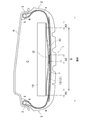
- FIG. 1 is a cross-sectional view of a meridian showing a pneumatic tire according to an embodiment of the present invention.
- FIG. 2 is a meridian cross-sectional view showing a pneumatic tire according to another embodiment of the present invention.
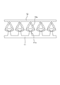
- FIG. 3 is an explanatory view schematically showing an example of the surface fastener of the present invention.
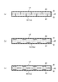
- 4 (a) to 4 (c) are explanatory views schematically showing an example of the repair liquid introduction section.
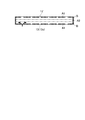
- 5 (a) to 5 (b) are explanatory views schematically showing another example of the repair liquid introduction portion.
- FIG. 6 is an explanatory diagram schematically showing another example of the repair liquid introduction section.
- 7 (a) to 7 (b) are explanatory views schematically showing another example of the repair liquid introduction portion.
- FIG. 8 is a schematic view illustrating the positional relationship of the repair liquid introduction portion.
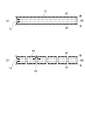
- 9 (a) to 9 (b) are cross-sectional views taken along the equator showing a pneumatic tire according to
- the pneumatic tire of the present invention has a tread portion 1, a pair of sidewall portions 2 arranged on both sides of the tread portion 1, and inside the sidewall portion 2 in the tire radial direction. It includes a pair of arranged bead portions 3.
- R in the figure represents a rim on which this pneumatic tire is mounted.
- FIGS. 1 and 2 are cross-sectional views of the meridian, the tread portion 1, the sidewall portion 2, and the bead portion 3 each extend in the tire circumferential direction to form an annular shape, whereby air is formed.
- the toroidal basic structure of the tire is constructed. Further, unless otherwise specified, other tire components in the meridian cross-sectional view extend in the tire circumferential direction to form an annular shape.
- a carcass layer 4 is mounted between the pair of left and right bead portions 3.
- the carcass layer 4 includes a plurality of reinforcing cords extending in the tire radial direction, and is folded back from the inside to the outside of the vehicle around the bead core 5 arranged in each bead portion 3.
- a bead filler 6 is arranged on the outer periphery of the bead core 5, and the bead filler 6 is wrapped by a main body portion and a folded portion of the carcass layer 4.
- a plurality of layers (two layers in FIG. 1) of belt layers 7 are embedded on the outer peripheral side of the carcass layer 4 in the tread portion 1.
- Each belt layer 7 includes a plurality of reinforcing cords that are inclined with respect to the tire circumferential direction, and the reinforcing cords are arranged so as to intersect each other between the layers.
- the inclination angle of the reinforcing cord with respect to the tire circumferential direction is set in the range of, for example, 10 ° to 40 °.
- a belt reinforcing layer (not shown) may be provided on the outer peripheral side of the belt layer 7.
- the belt reinforcement layer includes, for example, an organic fiber cord oriented in the tire circumferential direction.
- the angle of the organic fiber cord with respect to the tire circumferential direction can be set to, for example, 0 ° to 5 °.
- the present invention relates to an installation form when the sound absorbing material 10 is installed on such a general pneumatic tire as described later. Therefore, the basic cross-sectional structure of the pneumatic tire on which the sound absorbing material 10 is installed is not limited to the above-mentioned structure.
- the sound absorbing material 10 is installed in the tire cavity C.
- the sound absorbing material 10 is made of a porous material such as a sponge.
- the sound absorbing material 10 exhibits a predetermined sound absorbing characteristic due to its porous structure.
- the porous material constituting the sound absorbing material 10 for example, polyurethane foam can be exemplified.
- the illustrated sound absorbing material 10 has a substantially quadrangular shape in the meridian cross section and has a band-shaped structure extending in the tire circumferential direction, but the shape thereof is not particularly limited.
- the structure may have a surface facing the inner surface of the tread portion 1 (hereinafter, referred to as “tire inner surface”) and a surface facing the tire cavity C.
- the surface facing the inner surface of the tire and the surface facing the tire cavity C are curved surfaces, respectively, and have a substantially elliptical shape in the meridian cross section. It may be.
- the sound absorbing material 10 is installed on the inner surface of the tire via the hook-and-loop fastener.
- the hook-and-loop fastener is composed of a pair of a hook material 11 and a loop material 12.
- the hook material 11 is a member provided with a plurality of hook-shaped engaging elements 11e on one surface.
- the loop material 12 is a sheet material 12'provided with a loop-shaped engaging element 12e that can be engaged with the hook-shaped engaging element 11e.
- the hook-and-loop fastener composed of a pair of the hook material 11 and the loop material 12 is relatively flexible with respect to the hook material 11 (hook-shaped engaging element 11e) which is relatively hard.
- FIG. 3 schematically shows a state in which the loop material 12 (loop-shaped engaging element 12e) is engaged with the hook material 11 (hook-shaped engaging element 11e).
- a large number of hook-shaped engaging elements 11e and loop-shaped engaging elements 12e as shown in the figure are provided on one surface thereof over the entire surface.
- the physical properties of the loop material 12 are not particularly limited, but the elongation rate measured in accordance with the B method (constant load method for woven fabrics) specified in "8.16.1 Elongation rate" of JIS L1096 is preferably 5%. It is preferably ⁇ 35%, more preferably 10% to 30%. Since the loop material 12 having such an elongation rate can be deformed appropriately and flexibly with respect to the movement of the sound absorbing material 10 when the tire rolls, it is necessary to prevent the sound absorbing material 10 from falling off from the inner surface of the tire. It will be advantageous.
- the hook material 11 is fixed to the inner surface of the tire so that the hook-shaped engaging element 11e faces the tire cavity C side (loop material side 12).
- the method of fixing the hook material 11 to the inner surface of the tire is not particularly limited. For example, various methods such as adhesion, welding, and engagement using an engagement member separately provided on the inner surface of the tire can be adopted. Since the other surface of the hook material 11 is a surface fixed to the inner surface of the tire, it is processed into a structure (for example, a smooth surface in the case of adhesion) according to the method of fixing the hook material 11 to the inner surface of the tire. It is good to do. Preferably, the entire other surface of the hook material 11 is fixed to the inner surface of the tire.
- At least one hook member 11 is provided on the inner surface of the tire in the illustrated tire meridian cross section.
- the position for fixing the hook material 11 is set according to the arrangement of the sound absorbing material 10. For example, when one hook material 11 is provided as shown in FIG. 1, it is preferable to provide the hook material 11 near the center in the tire width direction. Further, when a plurality of hook members 11 are provided as shown in FIG. 2, it is preferable to arrange them at equal intervals, preferably at intervals in the tire width direction.
- the loop material 12 is fixed to the surface of the sound absorbing material 10 (the surface facing the inner surface of the tread portion 1) so that the loop-shaped engaging element 12e faces the tire inner surface side (hook material 11 side). Will be done.
- the method of fixing the loop material 12 to the sound absorbing material 10 is not particularly limited. For example, various methods such as adhesion, welding, and engagement using an engaging member separately provided on the sound absorbing material 10 can be adopted.
- the loop material 12 is made of a cloth material having an engaging element 12e made of loop-shaped fibers on the surface, the loop material 12 is sewn to the sound absorbing material 10 with a thread using a sewing machine or the like. You can also.
- the other surface of the loop material 12 is a surface fixed to the sound absorbing material 10, it may be processed into a structure according to the fixing method.
- the structure of the loop material 12 for example, when the loop material 12 is composed of cloth materials having the same quality on the front and back sides, even if the loop-shaped engaging element 12e is also present on the other surface. Good.
- the loop material 12 is not fixed to the entire sound absorbing material 10 or one of the tire inner surfaces in the tire width direction, but is not fixed to the entire sound absorbing material 10 or one of the tire inner surfaces in the tire width direction. Two places are partially fixed. For example, in the example of FIG. 1, the loop material 12 is fixed to the sound absorbing material, and in the example of FIG. 2, it is fixed (engaged) to the inner surface of the tire. As a result, the loop material 12 has a pair of first fixed regions A1 fixed to one of the sound absorbing material 10 or the inner surface of the tire and a non-fixed region not fixed to one of the sound absorbing material 10 or the inner surface of the tire. B is formed.
- the loop material 12 is located between at least a pair of first fixed regions A1 and a pair of first fixed regions A1 partially arranged on one of the surface of the sound absorbing material 10 or the inner surface of the tire in the tire meridian cross section. It has at least one non-fixed region B sandwiched between them.
- the portion where the loop material 12 is fixed to the sound absorbing material is the first fixing region A1
- the portion where the loop material 12 and the hook material 11 are engaged is the first.
- One fixed region A1 is the portion where the loop material 12 is fixed to the sound absorbing material.
- the loop material 12 is fixed to the sound absorbing material 10 or the other of the inner surfaces of the tires. Specifically, a part of the non-fixed region B (second fixed region A2) of the loop material 12 is fixed to the sound absorbing material 10 or the other of the tire inner surfaces.
- the loop material 12 is fixed (engaged) with respect to the inner surface of the tire in the second fixed region A2.
- the loop material 12 is fixed (engaged) to the inner surface of the tire in the first fixed region A1
- the loop material 12 is fixed to the sound absorbing material 10 in the second fixed region A2.
- the entire surface of the loop material 12 is not fixed to the sound absorbing material 10 or the inner surface of the tire, but the first fixed area A1 or the second fixed area Since only A2 is partially fixed to the sound absorbing material 10 and the inner surface of the tire, and the first fixed region A1 and the second fixed region A2 do not overlap, the loop material 12 and the loop material 12 are formed in each fixed region. While the sound absorbing material 10 or the inner surface of the tire is securely fixed, the flexibility of the loop material 12 can be maintained in the non-fixed region B in an unfixed state.
- a closed space D separated from the tire cavity C is formed by the tire inner surface or the sound absorbing material 10 and the non-fixed region B of the loop material 12.
- the closed space D is formed by the sound absorbing material 10 and the loop material 12
- the closed space D is formed by the tire inner surface and the loop material 12. Since this closed space D is basically cut off from the tire cavity C, when the tire punctures, a puncture repair liquid is injected into the tire via the tire valve to try to repair the puncture as an emergency. However, the puncture repair liquid cannot enter the closed space D.
- the repair liquid introduction portion 13 for connecting the closed space D and the tire cavity C is provided in a part of the loop material 12. Since the repair liquid introduction unit 13 connects the closed space D and the tire cavity C, the puncture repair liquid can enter the closed space D through the repair liquid introduction unit 13. As a result, in the pneumatic tire of the present invention, even if the sound absorbing material 10 is installed on the inner surface of the tire, the sound absorbing material 10 and its fixing means (the hook-and-loop fastener in the illustrated example) do not obstruct the flow of the puncture repair liquid. It becomes possible to perform puncture repair.
- the sound absorbing material 10 is fixed via the hook-and-loop fastener, but in the present invention, the sound absorbing material 10 is fixed via the sheet material 12'corresponding to the loop material 12 described above.
- the phrase "corresponding to the loop material 12 described above” is composed of a material having the same flexibility as the loop material 12 described above (cloth material, resin film material, rubber sheet material, or a composite material thereof, etc.). Similar to the loop material 12 described above, at least a pair of first fixing regions in which the sheet material 12'is fixed to either the inner surface of the tire or the surface of the sound absorbing material 10 in a part of the sheet material 12'in the tire width direction.
- It has A1 and has a non-fixed region B in which the sheet material 12'is not fixed to either the inner surface of the tire or the surface of the sound absorbing material 10 between the pair of first fixed regions A1, and at least one of the non-fixed regions B. It means that the portion has a second fixing region A2 for fixing the sheet material 12'to the inner surface of the tire or the other surface of the sound absorbing material 10. Since the sheet material 12'does not engage with the hook material 11, for example, an adhesive or double-sided tape is provided at the position of the hook material 11 in the drawing, and the sheet material 12'is partially provided on the inner surface of the tire or the sound absorbing material 10. Will be pasted.
- the sound absorbing material has a structure in which the sheet material 12'is flexible and is partially fixed to the inner surface of the tire or the sound absorbing material 10. Since the 10 and the inner surface of the tire do not come into close contact with each other, it is possible to prevent the flow of the puncture repair liquid from being obstructed by the sound absorbing material 10. Further, when the sheet material 12'is also used, the closed space D separated from the tire cavity C is formed by the tire inner surface or the sound absorbing material 10 and the non-fixed region B of the sheet material in the meridian cross section, so that the sheet material 12 is used. A repair liquid introduction portion 13 for connecting the closed space D and the tire cavity C is provided in a part of ′, so that the puncture repair liquid can enter the closed space D.
- FIGS. 4 to 7 schematically show the sheet material 12'(loop material 12).
- the vertical direction in the figure is the tire width direction
- the horizontal direction in the figure is the tire circumferential direction.
- the shaded area is the first fixed area A1
- the area centered in the width direction of the sheet material 12'divided by the alternate long and short dash line is the second fixed area A2
- the other part is the non-fixed area B.
- the first fixing region A1 is provided at least at the end of the seat material 12'in the tire width direction, and the seat material 12'is fixed to the inner surface of the tire or the sound absorbing material 10 (not shown).
- the first fixed region A1 is also provided at the end portion of the seat material 12'in the tire circumferential direction. That is, the sheet material 12'in FIGS. 4 to 6 has a bag shape with a closed periphery as a whole.
- FIGS. 6 and 7, for reference an example of the infiltration route of the puncture repair liquid is shown by an arrow.
- a plurality of slits 13a penetrating the sheet material 12' are provided as the repair liquid introduction portion 13.
- a plurality of slits 13a extending along the tire width direction from the first fixed region A1 to the second fixed region A2 so as to cross the non-fixed region B are formed in the tire circumferential direction. It is provided at intervals along.
- a plurality of slits 13a extending along the tire circumferential direction are spaced along the tire circumferential direction in each of the non-fixed regions B located on both sides of the second fixed region A2. It is provided in.
- the repair liquid introduction portions 13 are arranged in a staggered pattern with respect to the center of the sheet material 12'in the tire width direction.
- a plurality of slits 13a extending along the tire circumferential direction are provided in each of the non-fixed region B and the second fixed region A2 located on both sides of the second fixed region A2. It is provided at intervals along the direction.
- a perforation 13b penetrating the sheet material 12' is provided as the repair liquid introduction portion 13.
- a plurality of perforations 13b are provided at intervals along the tire circumferential direction in each of the non-fixed regions B located on both sides of the second fixed region A2.
- the perforations 13b are arranged in a staggered pattern with respect to the center of the sheet material 12'in the tire width direction.
- a plurality of perforations 13b are provided in each of the non-fixed region B and the second fixed region A2 located on both sides of the second fixed region A2 at intervals along the tire circumferential direction.
- an elliptical shape, a polygonal shape, or the like can be adopted.
- the gap 13c (the first fixed region A1 is missing) formed between the first fixed regions A1 adjacent to each other in the tire circumferential direction by providing the first fixed region A1 intermittently in the tire circumferential direction.
- Part functions as a repair liquid introduction unit 13.
- the total length of the tire circumferential length of the portion (gap 13c) where the first fixed region A1 is missing is the tire circumferential length of the sheet material 12'. It is preferably 2% to 50%.
- the entire circumference of the sheet material 12' (four sides consisting of a pair of circumferential end portions and a pair of widthwise end portions) is not set as the first fixed region A1, but the circumferential direction of the sheet material 12'.
- the opened end portion functions as the repair liquid introduction portion 13.
- the non-fixed region B over the entire length of the seat material 12'
- the non-fixed region B opened at the tire circumferential end of the seat material 12' functions as the repair liquid introduction portion 13.
- the circumferential end of one sheet material 12'extending over the entire length of the sound absorbing material 10 (not shown) is open.
- the puncture repair liquid infiltrates only from both ends in the circumferential direction of one sheet material 12'.
- a plurality of sheet materials 12' are arranged in the circumferential direction with respect to the sound absorbing material 10 (not shown) extending in the tire circumferential direction, and the circumferential direction of each sheet material 12'. The end is open.
- the puncture repair liquid infiltrates from the circumferential end of each sheet material 12'.
- the closed space D is formed by bending the sheet material 12'(loop material 12), but the sound absorbing material 10 is recessed with respect to the sheet material 12'(loop material 12). Even when the closed space D is formed in the above, by providing the above-mentioned repair liquid introducing portion 13, the puncture repair liquid can easily infiltrate into the closed space D, so that a reliable puncture repair can be performed.
- the sheet material 12' As the sheet material 12', as in the example of FIG. 7B, a plurality of sheet materials 12'divided in the tire circumferential direction may be provided, but workability when attaching the sheet material 12' From the viewpoint of cost, it is preferable to use the sheet material 12'continuous in the tire circumferential direction as shown in FIG. 7A. Further, if the seat material 12'is continuous in the tire circumferential direction as shown in FIG. 7A, the deformation of the seat material 12'when the tire touches the ground can be dispersed in the tire circumferential direction, so that the seat material can be dispersed. The load applied between the 12'and the sound absorbing material 10 or the inner surface of the tire can be reduced, and the durability can be improved.
- the second fixed region A2 is a region where the seat material 12'is joined to the inner surface of the tire or the sound absorbing material 10, so that the repair liquid introduction portion 13 is provided in this region.
- the repair liquid introduction portion 13 does not sufficiently function as a flow path for introducing the puncture repair liquid into the closed space D. Therefore, by providing the repair liquid introduction portion 13 at a position outside the second fixed region A2, it is possible to reliably introduce the puncture repair liquid into the closed space D.
- the position where the repair liquid introduction portion 13 is provided is not particularly limited, but as shown in FIG. 8, the shortest distance from an arbitrary point p on the sheet material 12'excluding the repair liquid introduction portion 13 to the repair liquid introduction portion 13 is set.
- the shortest distance from an arbitrary point p on the sheet material 12'excluding the repair liquid introduction portion 13 to the repair liquid introduction portion 13 is set.
- the maximum width of the sheet material 12'in the tire width direction is LW [mm]
- the maximum width LW [mm] preferably satisfy the following formula (1).
- the sound absorbing material 10 is omitted and only the tire body and the seat material 12'are schematically shown.
- FIG. 1 the sound absorbing material 10 is omitted and only the tire body and the seat material 12'are schematically shown.
- the shaded area is the first fixed area A1
- the area centered in the width direction of the sheet material 12'divided by the alternate long and short dash line is the second fixed area A2
- the other part is the non-fixed area B. Since the arbitrary point p is a point assumed as a failure location (puncture position), by satisfying the relationship of this equation (1), the distance from the repair liquid introduction unit 13 to the failure location becomes good, and the puncture repair The time it takes for the liquid to reach the faulty part can be shortened, which is advantageous for reliable puncture repair work. 0 mm ⁇ d ⁇ (LW / SW) ⁇ 200 mm ⁇ ⁇ ⁇ (1)
- the repair liquid introduction unit There is a risk that the distance from 13 to the arbitrary point p (failure point) will increase, and the air pressure will decrease by the time the puncture repair liquid reaches the failure point, falling below the level at which puncture repair is possible.
- the respective values of the shortest distance d [mm], the total tire width SW [mm], and the maximum width LW [mm] are not particularly limited, but the shortest distance d [mm] is preferable. It is preferably 250 mm or less, more preferably 220 mm or less.
- the sound absorbing material 10 is preferably a strip-shaped member extending in the tire circumferential direction as described above. At this time, as shown in FIG. 9, it is preferable to have a missing portion 14 in which the sound absorbing material 10 does not exist at at least one position in the tire circumferential direction. In addition, in FIG. 9A, one missing portion 14 is provided, and in FIG. 9B, three missing portions 14 are provided. When a plurality of missing portions 14 are provided as shown in FIG. 9B, since the plurality of sound absorbing materials 10 have a structure in which the plurality of sound absorbing materials 10 are intermittently arranged along the tire circumferential direction, the missing portions 14 are adjacent to each other. Corresponds to the gap of.
- the missing portion 14 By having such a missing portion 14, it is possible to withstand a long time for shear strain caused by expansion due to tire inflation and ground rolling. Further, since the missing portion 14 serves as a flow path for the puncture repair liquid that moves from one side to the other side of the sound absorbing material 10 in the tire width direction, it has an advantageous structure from the viewpoint of puncture repair. It is preferable that the missing portion 14 is provided at one location or three to five locations on the tire circumference. If the missing portions 14 are provided at two locations on the circumference of the tire, the deterioration of tire uniformity due to mass imbalance becomes remarkable, and if the missing portions 14 are provided at six or more locations on the circumference, the manufacturing cost increases significantly.
- the length of the missing portion 14 along the tire circumferential direction is preferably 5 mm or more and 150 mm or less, and more preferably 10 mm or more and 120 mm or less. If this length is less than 5 mm, the movement of the puncture repair liquid in the tire width direction may be hindered. If this length exceeds 150 mm, the weight balance in the tire circumferential direction may be lost and the tire uniformity may deteriorate.
- the sheet material 12' not only forms a closed space D to obstruct the flow of the puncture repair liquid, but can also be a factor of increasing the tire weight, so it is preferable to keep the sheet material 12'in an appropriate size.
- the total area S [mm 2 ] of the sheet material 12', the tire inner circumference L [mm] at the tire equator, and the maximum width BW [mm] of the belt layer satisfy the following equation (2). Is preferable.
- the size of the sheet material 12'(total area S) can be kept within an appropriate range, and the weight increase when the sound absorbing material 10 is provided via the sheet material 12'can be suppressed. 0.07 ⁇ S / (L ⁇ BW) ⁇ 1.0 ... (2)
- S / (L ⁇ BW) is 0.07 or less, it becomes impossible to sufficiently secure the force for joining the sound absorbing material 10 to the inner surface of the tire. If S / (L ⁇ BW) is 1.0 or more, the sheet material 12 ′ becomes large, and the tire weight may increase. S / (L ⁇ BW) is preferably 0.1 or more and 0.97 or less, and more preferably 0.15 or more and 0.85 or less. In the illustrated example, the sheet material 12'is fixed to the surface of the sound absorbing material 10 facing the inner surface of the tire, but if the range of the above formula (2) is satisfied, the upper surface of the sound absorbing material 10 (on the rim R). It may be provided so as to wrap around (opposing surfaces) and side surfaces (surfaces on both sides of the sound absorbing material 10 in the tire width direction).
Landscapes
- Engineering & Computer Science (AREA)
- Mechanical Engineering (AREA)
- Tires In General (AREA)
Abstract
タイヤ内面に吸音材が設置されていても、吸音材およびその固定手段によってパンク修理液の流れが阻害されずにパンク修理を行うことが可能な空気入りタイヤを提供する。トレッド部1の内面にシート材12を介して吸音材10を設置するにあたって、シート材のタイヤ幅方向の一部にシート材がタイヤ内面または吸音材10の一方に対して固定された少なくとも一対の第一固定領域A1を設け、この一対の第一固定領域A1の間にシート材がタイヤ内面または吸音材10の一方に対して固定されない非固定領域Bを設け、非固定領域Bの少なくとも一部にシート材をタイヤ内面または吸音材10の他方に対して固定する第二固定領域A2を設け、子午線断面においてタイヤ内面または吸音材10とシート材の非固定領域Bとによってタイヤ内腔Cから区切られた閉空間Dとタイヤ内腔Cとを接続する修理液導入部13をシート材に設ける。
Description
本発明は、タイヤ内面に吸音材が設置された空気入りタイヤに関し、更に詳しくは、吸音材およびその固定手段によってパンク修理液の流れが阻害されずにパンク修理を行うことを可能にした空気入りタイヤに関する。
近年、タイヤ騒音(特に、リム組み時にタイヤ内に形成される空洞部(タイヤ内腔)に充填された空気の振動による空洞共鳴音)を低減する方法として、タイヤ内腔にスポンジ等の多孔質材料からなる吸音材を設置することが提案されている。例えば、特許文献1の例では、スポンジ材からなる吸音材がトレッド部の内表面に接着剤や両面テープによって貼り付けられている。
一方で、車両に装着されたタイヤがパンクした際に、タイヤバルブを介してタイヤ内にパンク修理液を注入することにより、パンクを応急的に修理することが行われている。ところが、上記のように吸音材を備えた空気入りタイヤで、同様のパンク修理作業を行おうとすると、吸音材の設置形態によっては、吸音材自体や吸音材をタイヤ内面に固定するための固定部材によってパンク修理液の流れが阻害されて、適切に修理作業を行うことができない虞がある。例えば、特許文献1の例では、トレッド部の吸音材が設置された箇所にパンク等の故障が発生した場合、トレッド内面に密着した吸音材がパンク修理液の流れを阻害して、パンク修理液が故障箇所まで到達できないという不具合が生じる虞がある。
本発明の目的は、タイヤ内面に吸音材が設置されていても、吸音材およびその固定手段によってパンク修理液の流れが阻害されずにパンク修理を行うことを可能にした空気入りタイヤを提供することにある。
上記目的を達成するための本発明の空気入りタイヤは、タイヤ周方向に延在して環状をなすトレッド部と、前記トレッド部の両側に配置された一対のサイドウォール部と、これらサイドウォール部のタイヤ径方向内側に配置された一対のビード部とを備え、前記一対のビード部間に装架されたカーカス層と、前記トレッド部における前記カーカス層の外周側に配置された複数層のベルト層と、前記トレッド部の内面にシート材を介して設置された吸音材とを有する空気入りタイヤにおいて、前記シート材のタイヤ幅方向の一部に前記シート材が前記トレッド部の内面または前記吸音材の表面の一方に対して固定された少なくとも一対の第一固定領域を有し、前記一対の第一固定領域の間に前記シート材が前記トレッド部の内面または前記吸音材の表面の一方に対して固定されない非固定領域を有し、前記非固定領域の少なくとも一部に前記シート材を前記トレッド部の内面または前記吸音材の表面の他方に対して固定する第二固定領域を有し、子午線断面において前記トレッド部の内面または前記吸音材の表面と前記シート材の前記非固定領域とによってタイヤ内腔から区切られた閉空間が形成され、前記シート材の一部に前記閉空間とタイヤ内腔とを接続する修理液導入部が設けられたことを特徴とする。
本発明では、上述のように、吸音材がシート材を介して設置されるにあたって、シート材の全面を吸音材またはタイヤ内面の一方に対して固定せずに第一固定領域と非固定領域を設けたうえで、非固定領域中の第二固定領域を吸音材またはタイヤ内面の他方に対して固定しているので、第一固定領域および第二固定領域においてシート材と吸音材またはタイヤ内面を確実に固定しながら、非固定領域においてはシート材の柔軟性を固定されない状態のまま保持することができ、吸音材とタイヤ内面とがシート材を介して密着していない状態を保つことができる。そのため、パンク修理時にパンク修理液の流れが吸音材によって阻害されることを防止することができる。更に、一対の第一固定領域と非固定領域とによって必然的に形成される閉空間についても、上述のように修理液導入部が設けられているので、パンク修理液は修理液導入部を通じて閉空間内に到達することができる。その結果、吸音材やシート材が設けられていても、パンク修理液を故障箇所まで確実に導入することが可能になり、パンク修理作業を確実に行うことが可能になる。
本発明では、修理液導入部の少なくとも一部が第二固定領域のタイヤ幅方向外側に設けられることが好ましい。これにより、閉空間内に確実にパンク修理液を導入することが可能になる。
本発明では、修理液導入部を除いたシート材上の任意の点pから修理液導入部までの最短距離d[mm]と、タイヤ総幅SW[mm]と、タイヤ幅方向におけるシート材の最大幅LW[mm]とが、下記式(1)を満たすことが好ましい。これにより、パンク修理液が故障箇所まで到達する時間を短くすることができ、確実なパンク修理作業を行うには有利になる。
0mm<d×(LW/SW)≦200mm ・・・(1)
0mm<d×(LW/SW)≦200mm ・・・(1)
本発明では、シート材が吸音材のタイヤ周方向の全長に亘って連続的に延在していることが好ましい。このようにシート材が延在していることで、シート材の変形による負荷が周方向に分散されるため、固定領域の耐久性を向上することができる。また、シート材の製造工程やシート材を固定する工程の作業性を高めることができる。
本発明では、シート材が、複数本のフック状の係合素子を備えたフック材とフック状の係合素子に係合可能なループ状の係合素子を備えたループ材との対で構成された面ファスナーのループ材であり、シート材は、前記第一固定領域または第二固定領域においてトレッド部の内面に固定されたフック材に係合することでトレッド部の内面に固定されていることが好ましい。このようにシート材が面ファスナーのループ材であると、上述のように非固定領域においてシート材(ループ材)の柔軟性が保持されることで、柔軟性を保持したループ材がフック材に対して良好に作用して、面ファスナーの係合力を高めることができる。
本発明では、吸音材がタイヤ周方向に延在する帯状部材であり、タイヤ周方向の少なくとも1箇所に吸音材が存在しない欠落部を有し、欠落部のタイヤ周方向に沿った長さが5mm以上150mm以下であることが好ましい。このように吸音材が全周に亘って延在せずに欠落部を有することで、タイヤのインフレートによる膨張や接地転動に起因する剪断歪みに長時間耐えることが可能となり、吸音材の剥離を防止することができる。また、この欠落部は、タイヤ幅方向の一方側から他方側へ吸音材を超えて移動するパンク修理液の流路になるのでパンク修理を効率的に行うには有利になる。
本発明では、シート材の総面積S[mm2 ]と、タイヤ赤道におけるタイヤ内周長L[mm]と、ベルト層の最大幅BW[mm]とが下記式(2)を満たすことが好ましい。これによりシート材の大きさ(総面積S)を適度な範囲に収めることができ、シート材を介して吸音材を設ける際の重量増加を抑制することができる。
0.07<S/(L×BW)<1.0 ・・・(2)
0.07<S/(L×BW)<1.0 ・・・(2)
以下、本発明の構成について添付の図面を参照しながら詳細に説明する。
図1,2に示すように、本発明の空気入りタイヤは、トレッド部1と、このトレッド部1の両側に配置された一対のサイドウォール部2と、サイドウォール部2のタイヤ径方向内側に配置された一対のビード部3とを備えている。図中のRは、この空気入りタイヤが装着されるリムを表す。尚、図1,2は子午線断面図であるため描写されないが、トレッド部1、サイドウォール部2、ビード部3は、それぞれタイヤ周方向に延在して環状を成しており、これにより空気入りタイヤのトロイダル状の基本構造が構成される。また、子午線断面図における他のタイヤ構成部材についても、特に断りがない限り、タイヤ周方向に延在して環状を成している。
左右一対のビード部3間にはカーカス層4が装架されている。このカーカス層4は、タイヤ径方向に延びる複数本の補強コードを含み、各ビード部3に配置されたビードコア5の廻りに車両内側から外側に折り返されている。また、ビードコア5の外周上にはビードフィラー6が配置され、このビードフィラー6がカーカス層4の本体部と折り返し部とにより包み込まれている。一方、トレッド部1におけるカーカス層4の外周側には複数層(図1では2層)のベルト層7が埋設されている。各ベルト層7は、タイヤ周方向に対して傾斜する複数本の補強コードを含み、かつ層間で補強コードが互いに交差するように配置されている。これらベルト層7において、補強コードのタイヤ周方向に対する傾斜角度は例えば10°~40°の範囲に設定されている。更に、ベルト層7の外周側にはベルト補強層(不図示)を設けることもできる。ベルト補強層は、例えば、タイヤ周方向に配向する有機繊維コードを含む。ベルト補強層において、有機繊維コードはタイヤ周方向に対する角度が例えば0°~5°に設定することができる。
本発明は、このような一般的な空気入りタイヤに対して後述のように吸音材10を設置する際の設置形態に関するものである。そのため、吸音材10を設置する対象となる空気入りタイヤの基本的な断面構造は上述の構造に限定されるものではない。
本発明においては、タイヤ内腔Cに吸音材10が設置される。吸音材10は、スポンジ等の多孔質材料で構成される。吸音材10は、その多孔質構造によって所定の吸音特性を発揮するものである。吸音材10を構成する多孔質材料としては、例えば発泡ポリウレタンを例示することができる。図示の吸音材10は、子午線断面において略四角形状を有し、タイヤ周方向に延在する帯状の構造を有するが、その形状は特に限定されない。好ましくは、図示の例のように、トレッド部1の内表面(以下、「タイヤ内面」という)に対向する面とタイヤ内腔Cに対向する面とを有する構造にするとよい。このような構造としては、図示の断面略四角形状の他に、例えば、タイヤ内面に対向する面とタイヤ内腔Cに対向する面とがそれぞれ曲面であり、子午線断面において略楕円形状を有するものであってもよい。
図1,2の例では、吸音材10は面ファスナーを介してタイヤ内面に設置される。面ファスナーは、図3に拡大して示すように、フック材11とループ材12との対で構成される。フック材11とは、一方の面に複数本のフック状の係合素子11eを備えた部材である。ループ材12とは、フック状の係合素子11eに係合可能なループ状の係合素子12eを備えたシート材12′である。一般的に、フック材11とループ材12との対からなる面ファスナーは、相対的に硬質であるフック材11(フック状の係合素子11e)に対して、相対的に柔軟なループ材12(ループ状の係合素子12e)が絡み付くことで両者が係合されるものである。図3は、フック材11(フック状の係合素子11e)に対してループ材12(ループ状の係合素子12e)が係合した状態を模式的に示している。実際のフック材11やループ材12では、それぞれの一方の面に、図示のようなフック状の係合素子11eやループ状の係合素子12eが全面に亘って多数設けられている。
ループ材12の物性は特に限定されないが、JIS L1096の「8.16.1 伸び率」で規定されるB法(織物の定荷重法)に準拠して測定される伸び率が好ましくは5%~35%、より好ましくは10%~30%であるとよい。このような伸び率を有するループ材12は、タイヤ転動時の吸音材10の動きに対して適度に柔軟に変形することができるので、タイヤ内面からの吸音材10の脱落を防止するには有利になる。
フック材11は、図示のように、フック状の係合素子11eがタイヤ内腔C側(ループ材側12)を向くようにタイヤ内面に固定される。フック材11のタイヤ内面に対する固定方法は特に限定されない。例えば、接着、溶着、タイヤ内面に別途設けた係合部材を用いた係合などの様々な方法を採用することができる。フック材11の他方の面は、タイヤ内面の表面に対して固定される面であるので、フック材11のタイヤ内面に対する固定方法に応じた構造(例えば、接着の場合は平滑面など)に加工するとよい。好ましくは、フック材11の他方の面の全体がタイヤ内面に対して固定されているとよい。
フック材11は、図示のタイヤ子午線断面において、少なくとも1つがタイヤ内面に設けられる。フック材11を固定する位置は、吸音材10の配置に応じて設定されるが、例えば、図1のように1つのフック材11が設けられる場合は、タイヤ幅方向中心近傍に設けるとよい。また、図2のように複数のフック材11が設けられる場合は、タイヤ幅方向に間隔をおいて、好ましくは等間隔に配置するとよい。
ループ材12は、図示のように、ループ状の係合素子12eがタイヤ内面側(フック材11側)を向くように吸音材10の表面(トレッド部1の内表面に対向する面)に固定される。ループ材12の吸音材10に対する固定方法は特に限定されない。例えば、接着、溶着、吸音材10に別途設けた係合部材を用いた係合などの様々な方法を採用することができる。また、ループ材12が、表面にループ状の繊維からなる係合素子12eを備えた布材で構成される場合、ループ材12を吸音材10に対してミシン等を用いて糸で縫い付けることもできる。ループ材12の他方の面は、吸音材10に対して固定される面であるので、固定方法に応じた構造に加工するとよい。或いは、ループ材12の構造によっては(例えば、表裏が同質の布材でループ材12が構成される場合などには)、他方の面にもループ状の係合素子12eが存在していてもよい。
ループ材12は、図示のタイヤ子午線断面において、吸音材10またはタイヤ内面の一方のタイヤ幅方向の全体に固定されるものではなく、吸音材10またはタイヤ内面の一方に対してタイヤ幅方向の少なくとも2箇所が部分的に固定される。例えば、図1の例では、ループ材12は吸音材に対して固定され、図2の例では、タイヤ内面に対して固定(係合)される。その結果、ループ材12には、吸音材10またはタイヤ内面の一方に対して固定された一対の第一固定領域A1と、吸音材10またはタイヤ内面の一方に対して固定されていない非固定領域Bが形成される。言い換えると、ループ材12は、タイヤ子午線断面において、吸音材10の表面またはタイヤ内面の一方に部分的に配置された少なくとも一対の第一固定領域A1と、一対の第一固定領域A1の間に挟まれた少なくとも1つの非固定領域Bとを有している。尚、図1の例では、ループ材12が吸音材に対して固定された箇所が第一固定領域A1であり、図2の例ではループ材12とフック材11とが係合した箇所が第一固定領域A1である。
更に、ループ材12は、吸音材10またはタイヤ内面の他方に対して固定される。具体的には、ループ材12の非固定領域Bの一部(第二固定領域A2)が、吸音材10またはタイヤ内面の他方に対して固定される。例えば、図1の例では、第一固定領域A1ではループ材12が吸音材10に固定されるので、第二固定領域A2ではループ材12はタイヤ内面に対して固定(係合)される。図2の例では、第一固定領域A1ではループ材12がタイヤ内面に固定(係合)されるので、第二固定領域A2ではループ材12は吸音材10に対して固定される。
このように、面ファスナーを用いて吸音材10をタイヤ内面に設置する場合、ループ材12の全面を吸音材10やタイヤ内面に対して固定せずに、第一固定領域A1や第二固定領域A2のみが吸音材10やタイヤ内面に部分的に固定されるようにし、且つ、第一固定領域A1と第二固定領域A2とが重複しないようにしているので、各固定領域においてループ材12と吸音材10またはタイヤ内面を確実に固定しながら、非固定領域Bにおいてはループ材12の柔軟性を固定されない状態のまま保持することができる。このような固定形態では吸音材10とタイヤ内面とが密着しないため、タイヤがパンクした際に、タイヤバルブを介してタイヤ内にパンク修理液を注入して、パンクを応急的に修理する場合に、パンク修理液の流れが吸音材10によって阻害されることがなく、確実なパンク修理を行うことが可能になる。上記のように面ファスナーを用いている場合は、フック材11とループ材12とが係合するにあたって、柔軟性を保持したループ材12(非固定領域B)がフック材11に対して良好に作用するので、面ファスナーの係合力を高めることもできる。
このとき、子午線断面においてタイヤ内面または吸音材10とループ材12の非固定領域Bとによってタイヤ内腔Cから区切られた閉空間Dが形成される。具体的には、図1の例では、吸音材10とループ材12によって閉空間Dが形成され、図2の例では、タイヤ内面とループ材12とによって閉空間Dが形成される。この閉空間Dは、基本的にタイヤ内腔Cと遮断されるので、タイヤがパンクした際に、タイヤバルブを介してタイヤ内にパンク修理液を注入して、パンクを応急的に修理しようとしても、閉空間D内にはパンク修理液は浸入することができない。そのため、本発明では、ループ材12の一部に閉空間Dとタイヤ内腔Cとを接続する修理液導入部13を設けている。この修理液導入部13は、閉空間Dとタイヤ内腔Cとを接続するものであるので、パンク修理液は修理液導入部13を通じて閉空間D内に侵入することが可能になる。これにより、本発明の空気入りタイヤでは、タイヤ内面に吸音材10が設置されていても、吸音材10やその固定手段(図示の例では面ファスナー)によってパンク修理液の流れを阻害することなくパンク修理を行うことが可能になる。
尚、上述の説明では、吸音材10が面ファスナーを介して固定される場合を例示したが、本発明では、吸音材10が上述のループ材12に相当するシート材12′を介して固定されていればよい。「上述のループ材12に相当する」とは、上述のループ材12と同様の柔軟性を備えた材質(布材、樹脂フィルム材、ゴムシート材、またはこれらの複合材など)で構成されて、上述のループ材12と同様に、シート材12′のタイヤ幅方向の一部にシート材12′がタイヤ内面または吸音材10の表面の一方に対して固定された少なくとも一対の第一固定領域A1を有し、一対の第一固定領域A1の間にシート材12′がタイヤ内面または吸音材10の表面の一方に対して固定されない非固定領域Bを有し、非固定領域Bの少なくとも一部にシート材12′をタイヤ内面または吸音材10の表面の他方に対して固定する第二固定領域A2を有することを意味する。尚、シート材12′はフック材11と係合するものではないので、図中のフック材11の位置に例えば接着剤や両面テープを設けてシート材12′をタイヤ内面または吸音材10に部分的に貼り付けることになる。シート材12′を用いる場合、面ファスナーの係合力を高める効果は得られないが、シート材12′が柔軟でタイヤ内面または吸音材10に部分的に固定される構造であることで、吸音材10とタイヤ内面とが密着しないため、パンク修理液の流れが吸音材10によって阻害されることを防止することができる。また、シート材12′を用いる場合も、子午線断面においてタイヤ内面または吸音材10とシート材の非固定領域Bとによってタイヤ内腔Cから区切られた閉空間Dが形成されるので、シート材12′の一部に閉空間Dとタイヤ内腔Cとを接続する修理液導入部13を設けて、パンク修理液の閉空間D内への浸入を可能にする。
修理液導入部13としては、図4~7に示す様々な態様を採用することができる。これら修理液導入部13は組み合わせて採用することもできる。図4~7は、シート材12′(ループ材12)を模式的に示すものである。図の上下方向がタイヤ幅方向であり、図の左右方向がタイヤ周方向である。図4~7において、斜線部が第一固定領域A1、一点鎖線で区切られたシート材12′の幅方向中心の領域が第二固定領域A2、他の部分が非固定領域Bである。図示の例では、シート材12′の少なくともタイヤ幅方向端部に第一固定領域A1が設けられて、シート材12′は不図示のタイヤ内面または吸音材10に固定される。図4~6の例では、この他にシート材12′のタイヤ周方向端部にも第一固定領域A1が設けられている。即ち、図4~6のシート材12′は全体として周囲が閉じた袋状になっている。図6,7では、参考のためにパンク修理液の浸入経路の例を矢印で示している。
図4の例では、修理液導入部13としてシート材12′を貫通する複数のスリット13aが設けられている。図4(a)の例では、第一固定領域A1から第二固定領域A2に掛けて非固定領域Bを横断するようにタイヤ幅方向に沿って延在する複数のスリット13aが、タイヤ周方向に沿って間隔をおいて設けられている。図4(b)の例では、第二固定領域A2の両側に位置する非固定領域Bのそれぞれに、タイヤ周方向に沿って延在する複数のスリット13aが、タイヤ周方向に沿って間隔をおいて設けられている。いずれの場合も、修理液導入部13(スリット13a)は、シート材12′のタイヤ幅方向中心に対して千鳥状に配列されている。図4(c)の例では、第二固定領域A2の両側に位置する非固定領域Bと第二固定領域A2のそれぞれに、タイヤ周方向に沿って延在する複数のスリット13aが、タイヤ周方向に沿って間隔をおいて設けられている。
図5の例では、修理液導入部13としてシート材12′を貫通する穿孔13bが設けられている。図5(a)の例では、第二固定領域A2の両側に位置する非固定領域Bのそれぞれに、複数の穿孔13bが、タイヤ周方向に沿って間隔をおいて設けられている。このとき、穿孔13bは、シート材12′のタイヤ幅方向中心に対して千鳥状に配列されている。図5(b)の例では、第二固定領域A2の両側に位置する非固定領域Bと第二固定領域A2のそれぞれに、複数の穿孔13bが、タイヤ周方向に沿って間隔をおいて設けられている。穿孔13bの形状は図示の円形の他に、楕円形、多角形などを採用することができる。
図6の例では、第一固定領域A1をタイヤ周方向に断続的に設けることでタイヤ周方向に隣り合う第一固定領域A1の間に形成された隙間13c(第一固定領域A1が欠落した部分)が修理液導入部13として機能している。この場合、第一固定領域A1における接着性を確保するために、第一固定領域A1が欠落した部分(隙間13c)のタイヤ周方向長さの総和がシート材12′のタイヤ周方向長さの好ましくは2%~50%であるとよい。
図7の例では、シート材12′の全周(一対の周方向端部と一対の幅方向端部とからなる4辺)を第一固定領域A1にせずに、シート材12′の周方向端部を開放することで、この開放された端部が修理液導入部13として機能するようにしている。言い換えると、シート材12′の全長に亘って非固定領域Bを設けることで、シート材12′のタイヤ周方向端部において開放された非固定領域Bが修理液導入部13として機能するようにしている。図7(a)の例では、吸音材10(不図示)の全長に亘って延在する1枚のシート材12′の周方向端部を開放している。この例では、図示のように、1枚のシート材12′の周方向両端部のみからパンク修理液は浸入する。一方、図7(b)の例では、タイヤ周方向に延在する吸音材10(不図示)に対して、複数のシート材12′を周方向に配列し、各シート材12′の周方向端部を開放している。この例では、図示のように、各シート材12′の周方向端部からそれぞれパンク修理液が浸入する。
図1,2の例では、シート材12′(ループ材12)が撓むことで閉空間Dが形成されているが、吸音材10がシート材12′(ループ材12)に対して凹むことで閉空間Dが形成されている場合も、上述の修理液導入部13を設けることで、パンク修理液が閉空間Dに浸入しやすくなるので、確実なパンク修理が可能になる。
シート材12′として、図7(b)の例のように、タイヤ周方向に分割された複数枚のシート材12′を設けることもできるが、シート材12′を貼り付ける際の作業性やコスト面からは、図7(a)のようにタイヤ周方向に連続したシート材12′を用いることが好ましい。また、図7(a)のようにタイヤ周方向に連続したシート材12′であると、タイヤが接地した際のシート材12′の変形をタイヤ周方向に分散することができるので、シート材12′と吸音材10やタイヤ内面との間に掛かる負荷を軽減することができ耐久性を向上することができる。尚、図7のように周方向端部が修理液導入部13として機能する態様以外(図4~6のように、修理液導入部としてスリット13a、穿孔13b、隙間13cを設ける態様)も同様である。
上述の各種態様のいずれにおいても、修理液導入部13の少なくとも一部が第二固定領域A2のタイヤ幅方向外側に設けられることが好ましい。第二固定領域A2は、図1,2に示すように、シート材12′がタイヤ内面または吸音材10に対して接合される領域であるので、この領域に修理液導入部13が設けられても、閉空間D内にパンク修理液の導入する流路として充分に機能しない。そのため、修理液導入部13を第二固定領域A2から外れた位置に設けることで、閉空間D内に確実にパンク修理液を導入することが可能になる。
修理液導入部13を設ける位置は特に限定されないが、図8に示すように、修理液導入部13を除いたシート材12′上の任意の点pから修理液導入部13までの最短距離をd[mm]、タイヤ総幅をSW[mm]と、タイヤ幅方向におけるシート材12′の最大幅をLW[mm]としたとき、これら最短距離d[mm]とタイヤ総幅SW[mm]と最大幅LW[mm]とが下記式(1)を満たすことが好ましい。尚、図8では、吸音材10を省略してタイヤ本体とシート材12′のみを模式的に示している。図8では、斜線部が第一固定領域A1、一点鎖線で区切られたシート材12′の幅方向中心の領域が第二固定領域A2、他の部分が非固定領域Bである。任意の点pは故障箇所(パンク位置)として想定される点であるので、この式(1)の関係を満たすことで、修理液導入部13から故障箇所までの距離が良好になり、パンク修理液が故障箇所まで到達する時間を短くすることができ、確実なパンク修理作業を行うには有利になる。
0mm<d×(LW/SW)≦200mm ・・・(1)
0mm<d×(LW/SW)≦200mm ・・・(1)
上述の最短距離d[mm]とタイヤ総幅SW[mm]と最大幅LW[mm]とが式(1)を満たさず、d×(LW/SW)が200mmを超えると、修理液導入部13から任意の点p(故障箇所)までの距離が大きくなり、パンク修理液が故障箇所まで到達するまでに空気圧が低減してパンク修理が可能なレベルを下回る虞がある。上記式(1)を満たせば、最短距離d[mm]、タイヤ総幅SW[mm]、最大幅LW[mm]のそれぞれの値は特に限定されないが、最短距離d[mm]については好ましくは250mm以下、より好ましくは220mm以下であるとよい。
吸音材10は、上記のようにタイヤ周方向に延在する帯状部材であるとよい。このとき、図9に示すように、タイヤ周方向の少なくとも1箇所に吸音材10が存在しない欠落部14を有するとよい。尚、図9(a)では、1箇所の欠落部14が設けられ、図9(b)では3箇所の欠落部14が設けられている。図9(b)のように複数の欠落部14を設ける場合、複数の吸音材10がタイヤ周方向に沿って間欠的に配列された構造になるので、欠落部14は隣り合う吸音材10同士の隙間に相当する。このような欠落部14を有することで、タイヤのインフレートによる膨張や接地転動に起因する剪断歪みに長時間耐えることが可能となる。更に、欠落部14は、吸音材10のタイヤ幅方向の一方側から他方側へ移動するパンク修理液の流路となるので、パンク修理の面からも有利な構造である。この欠落部14は、タイヤ周上で1箇所または3~5箇所に設けることが好ましい。尚、欠落部14をタイヤ周上の2箇所に設けると質量アンバランスに起因するタイヤユニフォミティの悪化が顕著になり、周上の6箇所以上に設けると製造コストの増大が顕著になる。欠落部14のタイヤ周方向に沿った長さは好ましくは5mm以上150mm以下、より好ましくは10mm以上120mm以下である。この長さが5mm未満であると、パンク修理液のタイヤ幅方向の移動が阻害される虞がある。この長さが150mmを超えると、タイヤ周方向の重量バランスが崩れて、タイヤのユニフォミティが悪化する虞がある。
シート材12′は、閉空間Dを形成してパンク修理液の流れを阻害するだけでなく、タイヤ重量増加の要因にもなり得るので、適度な大きさに収めることが好ましい。具体的には、シート材12′の総面積S[mm2 ]と、タイヤ赤道におけるタイヤ内周長L[mm]と、ベルト層の最大幅BW[mm]とが下記式(2)を満たすことが好ましい。これによりシート材12′の大きさ(総面積S)を適度な範囲に収めることができ、シート材12′を介して吸音材10を設ける際の重量増加を抑制することができる。
0.07<S/(L×BW)<1.0 ・・・(2)
0.07<S/(L×BW)<1.0 ・・・(2)
S/(L×BW)が0.07以下であると、吸音材10をタイヤ内面に接合する力を充分に確保できなくなる。S/(L×BW)が1.0以上であると、シート材12′が大きくなり、タイヤ重量が増加する虞がある。S/(L×BW)は好ましくは0.1以上0.97以下、より好ましくは0.15以上0.85以下であるとよい。図示の例では、シート材12′は、吸音材10のタイヤ内面に対向する面に固定されているが、上記式(2)の範囲を満たしていれば、吸音材10の上面(リムRに対向する面)や側面(吸音材10のタイヤ幅方向両側の面)まで巻き付くように設けられていてもよい。
1 トレッド部
2 サイドウォール部
3 ビード部
4 カーカス層
5 ビードコア
6 フィラー層
7 ベルト層
10 吸音材
11 フック材
12 ループ材
12′ シート材
13 修理液導入部
14 欠落部
A1 第一固定領域
A2 第二固定領域
B 非固定領域
C タイヤ内腔
D 閉空間
2 サイドウォール部
3 ビード部
4 カーカス層
5 ビードコア
6 フィラー層
7 ベルト層
10 吸音材
11 フック材
12 ループ材
12′ シート材
13 修理液導入部
14 欠落部
A1 第一固定領域
A2 第二固定領域
B 非固定領域
C タイヤ内腔
D 閉空間
Claims (7)
- タイヤ周方向に延在して環状をなすトレッド部と、前記トレッド部の両側に配置された一対のサイドウォール部と、これらサイドウォール部のタイヤ径方向内側に配置された一対のビード部とを備え、前記一対のビード部間に装架されたカーカス層と、前記トレッド部における前記カーカス層の外周側に配置された複数層のベルト層と、前記トレッド部の内面にシート材を介して設置された吸音材とを有する空気入りタイヤにおいて、
前記シート材のタイヤ幅方向の一部に前記シート材が前記トレッド部の内面または前記吸音材の表面の一方に対して固定された少なくとも一対の第一固定領域を有し、
前記一対の第一固定領域の間に前記シート材が前記トレッド部の内面または前記吸音材の表面の一方に対して固定されない非固定領域を有し、
前記非固定領域の少なくとも一部に前記シート材を前記トレッド部の内面または前記吸音材の表面の他方に対して固定する第二固定領域を有し、
子午線断面において前記トレッド部の内面または前記吸音材の表面と前記シート材の前記非固定領域とによってタイヤ内腔から区切られた閉空間が形成され、
前記シート材の一部に前記閉空間とタイヤ内腔とを接続する修理液導入部が設けられたことを特徴とする空気入りタイヤ。 - 前記修理液導入部の少なくとも一部が前記第二固定領域のタイヤ幅方向外側に設けられたことを特徴とする請求項1に記載の空気入りタイヤ。
- 前記修理液導入部を除いた前記シート材上の任意の点pから前記修理液導入部までの最短距離d[mm]と、タイヤ総幅SW[mm]と、タイヤ幅方向における前記シート材の最大幅LW[mm]とが、下記式(1)を満たすことを特徴とする請求項1または2に記載の空気入りタイヤ。
0mm<d×(LW/SW)≦200mm ・・・(1) - 前記シート材が前記吸音材のタイヤ周方向の全長に亘って連続的に延在していることを特徴とする請求項1~3のいずれかに記載の空気入りタイヤ。
- 前記シート材が、複数本のフック状の係合素子を備えたフック材と前記フック状の係合素子に係合可能なループ状の係合素子を備えたループ材との対で構成された面ファスナーの前記ループ材であり、前記シート材は、前記第一固定領域または前記第二固定領域において前記トレッド部の内面に固定された前記フック材に係合することで前記トレッド部の内面に固定されていることを特徴とする請求項1~4のいずれかに記載の空気入りタイヤ。
- 前記吸音材がタイヤ周方向に延在する帯状部材であり、タイヤ周方向の少なくとも1箇所に前記吸音材が存在しない欠落部を有し、前記欠落部のタイヤ周方向に沿った長さが5mm以上150mm以下であることを特徴とする請求項1~5のいずれかに記載の空気入りタイヤ。
- 前記シート材の総面積S[mm2 ]と、タイヤ赤道におけるタイヤ内周長L[mm]と、前記ベルト層の最大幅BW[mm]とが下記式(2)を満たすことを特徴とする請求項1~6のいずれかに記載の空気入りタイヤ。
0.07<S/(L×BW)<1.0 ・・・(2)
Priority Applications (3)
| Application Number | Priority Date | Filing Date | Title |
|---|---|---|---|
| CN202080026774.5A CN113661076B (zh) | 2019-04-11 | 2020-04-03 | 充气轮胎 |
| DE112020000837.1T DE112020000837B4 (de) | 2019-04-11 | 2020-04-03 | Luftreifen |
| US17/594,171 US11999202B2 (en) | 2019-04-11 | 2020-04-03 | Pneumatic tire |
Applications Claiming Priority (2)
| Application Number | Priority Date | Filing Date | Title |
|---|---|---|---|
| JP2019-075832 | 2019-04-11 | ||
| JP2019075832A JP7238562B2 (ja) | 2019-04-11 | 2019-04-11 | 空気入りタイヤ |
Publications (1)
| Publication Number | Publication Date |
|---|---|
| WO2020209197A1 true WO2020209197A1 (ja) | 2020-10-15 |
Family
ID=72751591
Family Applications (1)
| Application Number | Title | Priority Date | Filing Date |
|---|---|---|---|
| PCT/JP2020/015321 Ceased WO2020209197A1 (ja) | 2019-04-11 | 2020-04-03 | 空気入りタイヤ |
Country Status (5)
| Country | Link |
|---|---|
| US (1) | US11999202B2 (ja) |
| JP (1) | JP7238562B2 (ja) |
| CN (1) | CN113661076B (ja) |
| DE (1) | DE112020000837B4 (ja) |
| WO (1) | WO2020209197A1 (ja) |
Families Citing this family (1)
| Publication number | Priority date | Publication date | Assignee | Title |
|---|---|---|---|---|
| WO2021133392A1 (en) * | 2019-12-26 | 2021-07-01 | Compagnie Generale Des Etablissements Michelin | Improved acoustic foam profile for pneumatic tires |
Citations (9)
| Publication number | Priority date | Publication date | Assignee | Title |
|---|---|---|---|---|
| JP2006044503A (ja) * | 2004-08-05 | 2006-02-16 | Yokohama Rubber Co Ltd:The | 空気入りタイヤ |
| JP2009292461A (ja) * | 2008-05-09 | 2009-12-17 | Yokohama Rubber Co Ltd:The | タイヤ騒音低減装置及びこれを装着した空気入りタイヤ |
| JP2016094163A (ja) * | 2014-11-17 | 2016-05-26 | 東洋ゴム工業株式会社 | 空気入りタイヤ |
| JP2016210250A (ja) * | 2015-05-01 | 2016-12-15 | 株式会社ブリヂストン | タイヤ |
| JP2017114163A (ja) * | 2015-12-21 | 2017-06-29 | 株式会社ブリヂストン | 空気入りタイヤ及びタイヤ・リム組立体 |
| JP2017202790A (ja) * | 2016-05-13 | 2017-11-16 | 東洋ゴム工業株式会社 | 空気入りタイヤ及び空気入りタイヤの製造方法 |
| JP2017202788A (ja) * | 2016-05-13 | 2017-11-16 | 東洋ゴム工業株式会社 | 空気入りタイヤ及び空気入りタイヤの製造方法 |
| JP2019031289A (ja) * | 2018-12-03 | 2019-02-28 | 株式会社ブリヂストン | タイヤ |
| WO2019039180A1 (ja) * | 2017-08-22 | 2019-02-28 | 住友ゴム工業株式会社 | 空気入りタイヤ |
Family Cites Families (15)
| Publication number | Priority date | Publication date | Assignee | Title |
|---|---|---|---|---|
| DE4001753A1 (de) * | 1990-01-22 | 1991-07-25 | Josef Piller | Reifen mit antilaermeinbau |
| JP3787343B2 (ja) * | 2003-11-07 | 2006-06-21 | 住友ゴム工業株式会社 | 空気入りタイヤとリムとの組立体 |
| JP4989449B2 (ja) * | 2007-12-25 | 2012-08-01 | 横浜ゴム株式会社 | 空気入りタイヤの製造方法及び空気入りタイヤ |
| JP5267288B2 (ja) * | 2008-05-09 | 2013-08-21 | 横浜ゴム株式会社 | タイヤ騒音低減装置 |
| JP4862918B2 (ja) * | 2009-06-05 | 2012-01-25 | 横浜ゴム株式会社 | 空気入りタイヤ |
| DE102009024454A1 (de) | 2009-06-10 | 2010-12-16 | Audi Ag | Luftreifen |
| JP5496797B2 (ja) * | 2010-07-05 | 2014-05-21 | 横浜ゴム株式会社 | 空気入りタイヤ |
| JP5760678B2 (ja) * | 2011-05-18 | 2015-08-12 | 横浜ゴム株式会社 | 空気入りタイヤ及びその製造方法 |
| CN105745087B (zh) * | 2013-11-21 | 2018-04-10 | 横滨橡胶株式会社 | 充气轮胎 |
| JP6294184B2 (ja) * | 2014-08-01 | 2018-03-14 | 東洋ゴム工業株式会社 | 空気入りタイヤ |
| JP6467950B2 (ja) * | 2015-01-29 | 2019-02-13 | 横浜ゴム株式会社 | 空気入りタイヤ |
| DE102015215738A1 (de) * | 2015-08-18 | 2017-02-23 | Continental Reifen Deutschland Gmbh | Fahrzeugluftreifen |
| JP6561727B2 (ja) * | 2015-09-28 | 2019-08-21 | 横浜ゴム株式会社 | 騒音低減装置及びそれを備えた空気入りタイヤ |
| DE102015221698A1 (de) * | 2015-11-05 | 2017-05-11 | Continental Reifen Deutschland Gmbh | Fahrzeugluftreifen |
| KR101861476B1 (ko) * | 2017-03-23 | 2018-07-05 | 한국타이어 주식회사 | 공명음 저감 공기압 타이어 |
-
2019
- 2019-04-11 JP JP2019075832A patent/JP7238562B2/ja active Active
-
2020
- 2020-04-03 WO PCT/JP2020/015321 patent/WO2020209197A1/ja not_active Ceased
- 2020-04-03 CN CN202080026774.5A patent/CN113661076B/zh active Active
- 2020-04-03 US US17/594,171 patent/US11999202B2/en active Active
- 2020-04-03 DE DE112020000837.1T patent/DE112020000837B4/de active Active
Patent Citations (9)
| Publication number | Priority date | Publication date | Assignee | Title |
|---|---|---|---|---|
| JP2006044503A (ja) * | 2004-08-05 | 2006-02-16 | Yokohama Rubber Co Ltd:The | 空気入りタイヤ |
| JP2009292461A (ja) * | 2008-05-09 | 2009-12-17 | Yokohama Rubber Co Ltd:The | タイヤ騒音低減装置及びこれを装着した空気入りタイヤ |
| JP2016094163A (ja) * | 2014-11-17 | 2016-05-26 | 東洋ゴム工業株式会社 | 空気入りタイヤ |
| JP2016210250A (ja) * | 2015-05-01 | 2016-12-15 | 株式会社ブリヂストン | タイヤ |
| JP2017114163A (ja) * | 2015-12-21 | 2017-06-29 | 株式会社ブリヂストン | 空気入りタイヤ及びタイヤ・リム組立体 |
| JP2017202790A (ja) * | 2016-05-13 | 2017-11-16 | 東洋ゴム工業株式会社 | 空気入りタイヤ及び空気入りタイヤの製造方法 |
| JP2017202788A (ja) * | 2016-05-13 | 2017-11-16 | 東洋ゴム工業株式会社 | 空気入りタイヤ及び空気入りタイヤの製造方法 |
| WO2019039180A1 (ja) * | 2017-08-22 | 2019-02-28 | 住友ゴム工業株式会社 | 空気入りタイヤ |
| JP2019031289A (ja) * | 2018-12-03 | 2019-02-28 | 株式会社ブリヂストン | タイヤ |
Also Published As
| Publication number | Publication date |
|---|---|
| CN113661076B (zh) | 2023-07-04 |
| US11999202B2 (en) | 2024-06-04 |
| DE112020000837T5 (de) | 2021-11-11 |
| JP2020172204A (ja) | 2020-10-22 |
| CN113661076A (zh) | 2021-11-16 |
| DE112020000837B4 (de) | 2024-03-14 |
| US20220176752A1 (en) | 2022-06-09 |
| JP7238562B2 (ja) | 2023-03-14 |
Similar Documents
| Publication | Publication Date | Title |
|---|---|---|
| EP2075112B1 (en) | Pneumatic tire manufacturing method and pneumatic tire | |
| US8052817B2 (en) | Manufacturing method of pneumatic tire | |
| US20190001760A1 (en) | Pneumatic tire and tire-and-rim assembly | |
| WO2002096678A1 (fr) | Poche d'air renforcee pour pneumatique de securite, procede de fabrication de la poche, et procede de fabrication de corps forme a couche de renforcement | |
| CA2115891C (en) | Protective barrier for tire sidewall | |
| JP2016088511A (ja) | 三次元部品を備える空気入りタイヤ | |
| JP2011207165A (ja) | タイヤの製造方法及びタイヤ | |
| JP6927221B2 (ja) | 空気入りタイヤ | |
| JP7238562B2 (ja) | 空気入りタイヤ | |
| CN110691702A (zh) | 充气轮胎 | |
| US7770620B2 (en) | Reinforced air bladder for safety tire | |
| JP6009255B2 (ja) | 空気入りタイヤ | |
| US20210101419A1 (en) | Pneumatic tire | |
| JP2004090807A (ja) | タイヤとリムの組立体 | |
| CN100473550C (zh) | 安全轮胎用加强气囊 | |
| CN113272153B (zh) | 充气轮胎 | |
| JP7469848B2 (ja) | 乗用車用空気入りラジアルタイヤ | |
| JP2011148392A (ja) | タイヤ用チューブ | |
| JP4549169B2 (ja) | 安全タイヤ用空気のう及び安全タイヤ | |
| JP4458347B2 (ja) | ランフラットタイヤ | |
| JP2025089726A (ja) | 空気入りタイヤ | |
| JP4916778B2 (ja) | ランフラットタイヤシステム | |
| JP2002002238A (ja) | 空気入りラジアルタイヤ | |
| WO2020085477A1 (ja) | タイヤ | |
| JP2007145287A (ja) | 安全タイヤ用空気のう及び安全タイヤ |
Legal Events
| Date | Code | Title | Description |
|---|---|---|---|
| 121 | Ep: the epo has been informed by wipo that ep was designated in this application |
Ref document number: 20786983 Country of ref document: EP Kind code of ref document: A1 |
|
| 122 | Ep: pct application non-entry in european phase |
Ref document number: 20786983 Country of ref document: EP Kind code of ref document: A1 |