WO2020195900A1 - Dispositif de chauffage - Google Patents
Dispositif de chauffage Download PDFInfo
- Publication number
- WO2020195900A1 WO2020195900A1 PCT/JP2020/010843 JP2020010843W WO2020195900A1 WO 2020195900 A1 WO2020195900 A1 WO 2020195900A1 JP 2020010843 W JP2020010843 W JP 2020010843W WO 2020195900 A1 WO2020195900 A1 WO 2020195900A1
- Authority
- WO
- WIPO (PCT)
- Prior art keywords
- heat generating
- distance
- generating portion
- electrode
- detection
- Prior art date
Links
Images


Classifications
-
- B—PERFORMING OPERATIONS; TRANSPORTING
- B60—VEHICLES IN GENERAL
- B60H—ARRANGEMENTS OF HEATING, COOLING, VENTILATING OR OTHER AIR-TREATING DEVICES SPECIALLY ADAPTED FOR PASSENGER OR GOODS SPACES OF VEHICLES
- B60H1/00—Heating, cooling or ventilating [HVAC] devices
- B60H1/22—Heating, cooling or ventilating [HVAC] devices the heat being derived otherwise than from the propulsion plant
- B60H1/2215—Heating, cooling or ventilating [HVAC] devices the heat being derived otherwise than from the propulsion plant the heat being derived from electric heaters
- B60H1/2218—Heating, cooling or ventilating [HVAC] devices the heat being derived otherwise than from the propulsion plant the heat being derived from electric heaters controlling the operation of electric heaters
-
- B—PERFORMING OPERATIONS; TRANSPORTING
- B60—VEHICLES IN GENERAL
- B60H—ARRANGEMENTS OF HEATING, COOLING, VENTILATING OR OTHER AIR-TREATING DEVICES SPECIALLY ADAPTED FOR PASSENGER OR GOODS SPACES OF VEHICLES
- B60H1/00—Heating, cooling or ventilating [HVAC] devices
- B60H1/00642—Control systems or circuits; Control members or indication devices for heating, cooling or ventilating devices
- B60H1/00735—Control systems or circuits characterised by their input, i.e. by the detection, measurement or calculation of particular conditions, e.g. signal treatment, dynamic models
- B60H1/00742—Control systems or circuits characterised by their input, i.e. by the detection, measurement or calculation of particular conditions, e.g. signal treatment, dynamic models by detection of the vehicle occupants' presence; by detection of conditions relating to the body of occupants, e.g. using radiant heat detectors
-
- B—PERFORMING OPERATIONS; TRANSPORTING
- B60—VEHICLES IN GENERAL
- B60H—ARRANGEMENTS OF HEATING, COOLING, VENTILATING OR OTHER AIR-TREATING DEVICES SPECIALLY ADAPTED FOR PASSENGER OR GOODS SPACES OF VEHICLES
- B60H1/00—Heating, cooling or ventilating [HVAC] devices
- B60H1/00642—Control systems or circuits; Control members or indication devices for heating, cooling or ventilating devices
- B60H1/00735—Control systems or circuits characterised by their input, i.e. by the detection, measurement or calculation of particular conditions, e.g. signal treatment, dynamic models
- B60H1/00792—Arrangement of detectors
-
- B—PERFORMING OPERATIONS; TRANSPORTING
- B60—VEHICLES IN GENERAL
- B60H—ARRANGEMENTS OF HEATING, COOLING, VENTILATING OR OTHER AIR-TREATING DEVICES SPECIALLY ADAPTED FOR PASSENGER OR GOODS SPACES OF VEHICLES
- B60H1/00—Heating, cooling or ventilating [HVAC] devices
- B60H1/22—Heating, cooling or ventilating [HVAC] devices the heat being derived otherwise than from the propulsion plant
- B60H1/2215—Heating, cooling or ventilating [HVAC] devices the heat being derived otherwise than from the propulsion plant the heat being derived from electric heaters
- B60H1/2226—Electric heaters using radiation
-
- B—PERFORMING OPERATIONS; TRANSPORTING
- B60—VEHICLES IN GENERAL
- B60H—ARRANGEMENTS OF HEATING, COOLING, VENTILATING OR OTHER AIR-TREATING DEVICES SPECIALLY ADAPTED FOR PASSENGER OR GOODS SPACES OF VEHICLES
- B60H1/00—Heating, cooling or ventilating [HVAC] devices
- B60H1/22—Heating, cooling or ventilating [HVAC] devices the heat being derived otherwise than from the propulsion plant
- B60H1/2215—Heating, cooling or ventilating [HVAC] devices the heat being derived otherwise than from the propulsion plant the heat being derived from electric heaters
- B60H1/2227—Electric heaters incorporated in vehicle trim components, e.g. panels or linings
-
- H—ELECTRICITY
- H05—ELECTRIC TECHNIQUES NOT OTHERWISE PROVIDED FOR
- H05B—ELECTRIC HEATING; ELECTRIC LIGHT SOURCES NOT OTHERWISE PROVIDED FOR; CIRCUIT ARRANGEMENTS FOR ELECTRIC LIGHT SOURCES, IN GENERAL
- H05B1/00—Details of electric heating devices
- H05B1/02—Automatic switching arrangements specially adapted to apparatus ; Control of heating devices
- H05B1/0227—Applications
- H05B1/023—Industrial applications
- H05B1/0236—Industrial applications for vehicles
-
- H—ELECTRICITY
- H05—ELECTRIC TECHNIQUES NOT OTHERWISE PROVIDED FOR
- H05B—ELECTRIC HEATING; ELECTRIC LIGHT SOURCES NOT OTHERWISE PROVIDED FOR; CIRCUIT ARRANGEMENTS FOR ELECTRIC LIGHT SOURCES, IN GENERAL
- H05B3/00—Ohmic-resistance heating
- H05B3/02—Details
- H05B3/03—Electrodes
-
- H—ELECTRICITY
- H05—ELECTRIC TECHNIQUES NOT OTHERWISE PROVIDED FOR
- H05B—ELECTRIC HEATING; ELECTRIC LIGHT SOURCES NOT OTHERWISE PROVIDED FOR; CIRCUIT ARRANGEMENTS FOR ELECTRIC LIGHT SOURCES, IN GENERAL
- H05B3/00—Ohmic-resistance heating
- H05B3/20—Heating elements having extended surface area substantially in a two-dimensional plane, e.g. plate-heater
- H05B3/22—Heating elements having extended surface area substantially in a two-dimensional plane, e.g. plate-heater non-flexible
- H05B3/26—Heating elements having extended surface area substantially in a two-dimensional plane, e.g. plate-heater non-flexible heating conductor mounted on insulating base
- H05B3/267—Heating elements having extended surface area substantially in a two-dimensional plane, e.g. plate-heater non-flexible heating conductor mounted on insulating base the insulating base being an organic material, e.g. plastic
-
- B—PERFORMING OPERATIONS; TRANSPORTING
- B60—VEHICLES IN GENERAL
- B60H—ARRANGEMENTS OF HEATING, COOLING, VENTILATING OR OTHER AIR-TREATING DEVICES SPECIALLY ADAPTED FOR PASSENGER OR GOODS SPACES OF VEHICLES
- B60H1/00—Heating, cooling or ventilating [HVAC] devices
- B60H1/22—Heating, cooling or ventilating [HVAC] devices the heat being derived otherwise than from the propulsion plant
- B60H2001/2228—Heating, cooling or ventilating [HVAC] devices the heat being derived otherwise than from the propulsion plant controlling the operation of heaters
- B60H2001/224—Heating, cooling or ventilating [HVAC] devices the heat being derived otherwise than from the propulsion plant controlling the operation of heaters automatic operation, e.g. control circuits or methods
-
- H—ELECTRICITY
- H05—ELECTRIC TECHNIQUES NOT OTHERWISE PROVIDED FOR
- H05B—ELECTRIC HEATING; ELECTRIC LIGHT SOURCES NOT OTHERWISE PROVIDED FOR; CIRCUIT ARRANGEMENTS FOR ELECTRIC LIGHT SOURCES, IN GENERAL
- H05B2203/00—Aspects relating to Ohmic resistive heating covered by group H05B3/00
- H05B2203/032—Heaters specially adapted for heating by radiation heating
Definitions
- This disclosure relates to a heater device.
- Patent Document 1 there is a device described in Patent Document 1.
- This device has a heat generating part that generates heat when energized, a plurality of electrodes for detecting a change in capacitance due to an object around the heat generating part, and an object close to each other based on the change in capacitance between the plurality of electrodes. It is provided with a proximity detection unit for detecting the above and an energization control unit for controlling energization to the heat generating unit based on the proximity of the object detected by the proximity detection unit.
- the capacitance between a plurality of electrodes changes depending on the energization of the heat generating portion. Further, according to the study of the inventor, it was found that the capacitance between the plurality of electrodes also changes due to the heat shrinkage of each electrode due to the heat generation of the heat generating portion. Further, according to the study of the inventor, if the capacitance between the electrodes changes due to such an external factor, the proximity of the object may not be detected.
- An object of the present disclosure is to enable more accurate detection of the proximity of an object around a heat generating portion even if the capacitance between electrodes changes due to an external factor.
- the heater device determines whether or not the distance between the heat generating portion that generates heat by energization and the object around the heat generating portion and the heat generating portion with the first detection sensitivity is equal to or less than the first detection distance. Whether or not the distance between the object around the heat generating portion and the heat generating portion is shorter than the first detection distance and equal to or less than the second detection distance with the second detection sensitivity, which is lower than the first detection sensitivity. It is provided with a detection unit for detecting.
- FIG. 6 is a sectional view taken along line IV-IV in FIG. It is a figure for demonstrating the operation principle of the mutual capacitance type capacitance sensor. It is a figure for demonstrating the operation principle of the mutual capacitance type capacitance sensor. It is a figure which showed the relationship between the distance to an object, the change of a capacitance, and the judgment value. It is a flowchart of a control part.
- FIG. 5 is a cross-sectional view taken along the line XX in FIG. It is a figure which showed the whole structure of the heater device which concerns on 3rd Embodiment, and is the figure which omitted the insulating base material. It is a figure which showed the modification of the heater device. It is a figure which showed the modification of the heater device.
- the heater device 20 is installed in the room of a moving body such as a road traveling vehicle.
- the heater device 20 constitutes a part of the heating device for the room.
- the heater device 20 is an electric heater that generates heat by being supplied with power from a power source such as a battery or a generator mounted on a moving body.
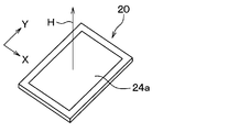
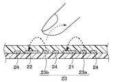
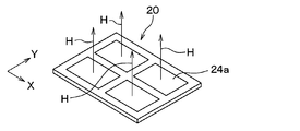
- the heater device 20 is formed in a thin plate shape. The heater device 20 generates heat when electric power is supplied. As shown in FIG.
- the heater device 20 has a surface having a heat generating surface 24a that radiates radiant heat H mainly in a direction perpendicular to the surface in order to warm an object positioned in a direction perpendicular to the surface thereof. It can be called a state heater.
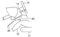
- the heater device 20 is installed indoors so as to radiate radiant heat H to the feet of the occupant 12.
- the heater device 20 can be used as a device for promptly providing warmth to the occupant 12 immediately after, for example, starting another heating device.
- the heater device 20 is installed on the wall surface of the room.
- the heater device 20 is installed so as to face the occupant 12 in the assumed normal posture.
- the road traveling vehicle has a steering column 14 for supporting the steering wheel 13.
- the heater device 20 is installed on the lower surface of the steering column 14 and the lower surface of the instrument panel cover 15 so as to face the occupant 12.
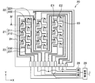
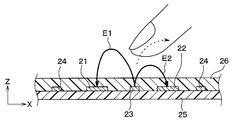
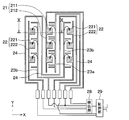
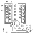
- the heater device 20 includes a first receiving electrode 21, a second receiving electrode 22, a transmitting electrode 23, a heat generating unit 24, an insulating base material 25, a cover member 26, a detecting unit 28, and a control unit. It has 29.
- the cover member 26 is omitted.
- the first receiving electrode 21 is shown by line hatching and the second receiving electrode 22 is shown by point hatching.
- the insulating base material 25 corresponds to a substrate.
- the insulating base material 25 is composed of a plate-shaped member extending along an XY plane defined by an axis X and an axis Y.
- the insulating base material 25 has a thickness in the direction of the axis Z.
- the insulating base material 25 is formed in a substantially quadrangular thin plate shape.
- the insulating base material 25 is made of a resin material having high insulating properties and withstanding high temperatures, for example, a polyimide film.
- the first receiving electrode 21, the second receiving electrode 22, the transmitting electrode 23, and the heat generating portion 24 are formed on the surface of the insulating base material 25 on the occupant side.
- the first receiving electrode 21, the second receiving electrode 22, the transmitting electrode 23, and the heat generating portion 24 are made of a thin copper film, and the heater device 20 is made thinner and has a lower heat capacity. Further, due to the reduced heat capacity, the temperature of the heat generating portion 24 rises rapidly due to energization. Further, when the object comes into contact with the heat generating surface 24a, the temperature of the contacted portion can be rapidly lowered. Further, the first receiving electrode 21, the second receiving electrode 22, and the transmitting electrode 23 are connected to the detection unit 28.
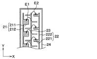
- the first receiving electrode 21 has a plurality of plate-shaped portions 211 formed so as to expand in the XY plane direction, and a connecting portion 212 connecting between the plate-shaped portions 211.
- the plurality of plate-shaped portions 211 each have a rectangular shape, and the connecting portion 212 has a linear shape.
- the second receiving electrode 22 has a plurality of plate-shaped portions 221 formed so as to expand in the XY plane direction, and a connecting portion 222 connecting between the plate-shaped portions 221.
- Each plate-shaped portion 221 has a rectangular shape
- the connecting portion 222 has a linear shape.
- each plate-shaped portion 211 of the first receiving electrode 21 has the same shape and area as each plate-shaped portion 221 of the second receiving electrode 22.
- the transmitting electrode 23 has a main line portion 231 and a plurality of branched portions 232 that branch off from the main line portion 231.
- the transmitting electrode 23 is arranged between the first receiving electrode 21 and the second receiving electrode 22 at a predetermined distance from the first receiving electrode 21 and the second receiving electrode 22.
- two branch-shaped portions 232 of the transmitting electrode 23 are arranged between the plate-shaped portions 211 of the first receiving electrodes 21 arranged side by side in the Y-axis direction. Further, one branch-shaped portion 232 of the transmitting electrode 23 is arranged between the plate-shaped portions 221 of the second receiving electrodes 22 arranged side by side in the Y-axis direction.
- the distance in the Y direction between the plate-shaped portion 211 of the first receiving electrode 21 and the branched portion 232 of the transmitting electrode 23 is the branch-shaped portion of the plate-shaped portion 221 of the second receiving electrode 22 and the transmitting electrode 23. It is shorter than the distance in the Y direction from 232.
- the capacitance formed between the transmitting electrode 23 and the first receiving electrode 21 is larger than the capacitance formed between the transmitting electrode 23 and the second receiving electrode 22. That is, the electric line of force E1 formed between the transmitting electrode 23 and the first receiving electrode 21 is larger than the electric line of force E2 formed between the transmitting electrode 23 and the second receiving electrode 22.
- the detection unit 28 of the present embodiment has a signal corresponding to a change in capacitance between the transmitting electrode 23 and the first receiving electrode 21, and a capacitance between the transmitting electrode 23 and the second receiving electrode 22.
- the signal corresponding to the change is amplified by the amplifier.
- the detection unit 28 detects whether or not the distance between the object around the heat generation unit 24 and the heat generation unit 24 is equal to or less than the first detection distance L1 with the first detection sensitivity. Further, the detection unit 28 determines whether or not the distance between the object around the heat generation unit 24 and the heat generation unit 24 is equal to or less than the second detection distance L2 with the second detection sensitivity lower than the first detection sensitivity. To detect.
- the detection unit 28 determines whether or not the distance between the object and the heat generating unit 24 is equal to or less than the second detection distance L2 and the signal indicating whether or not the distance between the object and the heat generating unit 24 is the first detection distance L1 or less. A signal indicating this is output to the control unit 29.
- the heat generating portion 24 has a linear shape and is formed so as to meander on one surface of the insulating base material 25.
- the heat generating unit 24 radiates radiant heat H that makes the occupant 12 feel warm by energizing from the control unit 29.
- the heat generating portion 24 is made of a material having a high thermal conductivity.
- the heat generating portion 24 can be configured by using a metal such as copper, an alloy of copper and tin (Cu—Sn), silver, tin, stainless steel, nickel, dichrome, and an alloy containing these.
- the cover member 26 protects the first receiving electrode 21, the second receiving electrode 22, the transmitting electrode 23, and the heat generating portion 24.
- the cover member 26 is composed of a first receiving electrode 21, a second receiving electrode 22, a transmitting electrode 23, and a low thermal conductive member having a lower thermal conductivity than the heat generating portion 24.
- the control unit 29 is configured as a computer equipped with a CPU, memory, I / O, etc., and the CPU executes various processes according to a program stored in the memory.
- Memory is a non-transitional substantive storage medium.
- the heater device 20 of this embodiment is configured as a mutual capacitance type capacitance sensor.
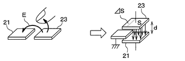
- the operating principle of the mutual capacitance type capacitance sensor will be described with reference to FIGS. 5 to 6.
- it will be described as a capacitance sensor having a transmitting electrode 23 and a first receiving electrode 21.
- the left side in FIG. 5 shows a schematic diagram of the transmitting electrode 23 and the first receiving electrode 21, and the right side in FIG. 5 shows the equivalent circuit of the transmitting electrode 23 and the first receiving electrode 21.
- the transmitting electrode 23 and the first receiving electrode 21 are arranged adjacent to each other. Then, when a voltage is applied between the transmitting electrode 23 and the first receiving electrode 21, an electric field is formed between the transmitting electrode 23 and the first receiving electrode 21.
- Equation 1 the dielectric constant between the transmitting electrode 23 and the first receiving electrode 21 is ⁇ , the area of each electrode is S, and the distance between the electrodes is d, the transmitting electrode 23 and the first receiving electrode 21 The capacitance C between them can be expressed as in Equation 1.
- Equation 2 the capacitance C between the transmitting electrode 23 and the first receiving electrode 21 can be expressed as in Equation 2.
- the proximity of the finger can be detected by determining the difference between the capacitance C shown in the formula 1 and the capacitance C'shown in the formula 2.
- the detection unit 28 detects whether or not the distance between the object around the heat generation unit 24 and the heat generation unit 24 is equal to or less than the first detection distance L1 with the first detection sensitivity. Further, the detection unit 28 determines whether or not the distance between the object around the heat generation unit 24 and the heat generation unit 24 is equal to or less than the second detection distance L2 with the second detection sensitivity lower than the first detection sensitivity. To detect.
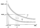
- FIG. 7 shows the relationship between the change C1 of the capacitance between the first receiving electrode 21 and the transmitting electrode 23 with respect to the distance L to the object in the heater device 20 of the present embodiment, and the second reception with respect to the distance L to the object.
- the relationship of the change C2 of the capacitance between the electrode 22 and the transmitting electrode 23 is shown.
- the change C1 of the capacitance between the first receiving electrode 21 and the transmitting electrode 23 is configured to be larger than the change C2 of the capacitance between the second receiving electrode 22 and the transmitting electrode 23. Has been done.
- the change in capacitance between the second receiving electrode 22 and the transmitting electrode 23 and the second receiving electrode 22 and the transmitting electrode 23 under the operating temperature environment varies depending on external factors such as temperature.
- the operating temperature environment means, for example, an environment of ⁇ 10 ° C. to 120 ° C.
- the lower limit value of the change in capacitance C1 between the first receiving electrode 21 and the transmitting electrode 23 is the capacitance between the second receiving electrode 22 and the transmitting electrode 23. It is configured to be larger than the upper limit of the change C2.
- the lower limit value L1D of the first detection distance L1 under the operating temperature environment is larger than the upper limit value L2U of the second detection distance L2 under the operating temperature environment.
- the lower limit of the first detection distance under the operating temperature environment is not smaller than the upper limit of the second detection distance under the operating temperature environment, and the proximity of the object is detected with high accuracy. ..
- control unit 29 determines in S100 whether or not the distance between the object around the heat generating unit 24 and the heat generating unit 24 is equal to or less than the first detection distance L1. Specifically, it is determined whether or not the distance between the object and the heat generating unit 24 is equal to or less than the first detection distance L1 based on the output signal of the detection unit 28.
- the control unit 29 when it is determined in S100 that the distance between the object around the heat generating unit 24 and the heat generating unit 24 is not equal to or less than the first detection distance L1, the control unit 29 together with the object and the heat generating unit 24 in S104. It is determined whether or not the distance of is equal to or less than the second detection distance L2. Specifically, it is determined whether or not the distance between the object and the heat generating unit 24 is equal to or less than the second detection distance L2 based on the output signal of the detection unit 28. Then, when it is determined that the distance between the object and the heat generating unit 24 is not equal to or less than the second detection distance L2, the control unit 29 ends this process. Therefore, the energization of the heat generating portion 24 is continued.
- control unit 29 sets the heater temperature of the heat generating unit 24 to the first in S102. Reduce to temperature. As a result, the temperature of the heat generating portion 24 is lowered.
- control unit 29 determines in S104 whether or not the distance between the object and the heat generating unit 24 is equal to or less than the second detection distance L2. Specifically, it is determined whether or not the distance between the object and the heat generating unit 24 is equal to or less than the second detection distance L2 based on the output signal of the detection unit 28.
- the control unit 29 stops the energization of the heat generating unit 24 and stops the operation of the heat generating unit 24 in S106. Let me. As a result, the temperature of the heat generating portion 24 is further lowered, and the thermal discomfort to the occupant can be reduced.
- the heater device 20 of the present embodiment includes a heat generating portion 24 that generates heat when energized.
- the detection unit 28 detects whether or not the distance between the object and the heat generating unit 24 is equal to or less than the first detection distance L1 with the first detection sensitivity, and the second detection sensitivity is lower than the first detection sensitivity. With the detection sensitivity, it is detected whether or not the distance between the object and the heat generating portion 24 is the second detection distance L2 or less, which is shorter than the first detection distance.
- the heater device 20 sets the heater temperature of the heat generating unit 24 to the first.
- a first temperature lowering unit (S102) for lowering the temperature to the above temperature is provided.
- the second temperature lowering unit that stops energization of the heat generating unit 24 is stopped. (S106) is provided. Therefore, it is possible to reduce the thermal discomfort to the occupant.
- the lower limit value L1D of the first detection distance L1 under the operating temperature environment is larger than the upper limit value L2U of the second detection distance L2 under the operating temperature environment. Therefore, the lower limit value L1D of the first detection distance L1 under the operating temperature environment is not smaller than the upper limit value L2U of the second detection distance L2 under the operating temperature environment, and the proximity of the object can be detected accurately. ..
- the heater device 20 includes receiving electrodes 21, 22 and transmitting electrodes 23. Then, the detection unit 28 detects whether or not the distance between the object and the heat generating unit 24 is equal to or less than the first detection distance L1 based on the change in capacitance between the receiving electrodes 21 and 22 and the transmitting electrode 23. To do. Further, it is determined whether or not the distance between the object around the heat generating portion 24 and the heat generating portion 24 is equal to or less than the second detection distance L2 based on the change in capacitance between the receiving electrodes 21 and 22 and the transmitting electrode 23. To detect.
- the distance between the object and the heat generating portion 24 can be detected based on the change in capacitance between the receiving electrodes 21 and 22 and the transmitting electrode 23.
- the insulating base material 25 on which the heat generating portion 24, the receiving electrodes 21, 22 and the transmitting electrode 23 are formed is provided, and the heat generating portion 24, the receiving electrodes 21, 22 and the transmitting electrode 23 are formed on the same surface of the insulating base material 25. Has been done. Therefore, the structure can be simplified and the manufacturing cost can be reduced.
- the receiving electrodes 21 and 22 have a first receiving electrode 21 and a second receiving electrode 22.
- the distance between the object around the heat generation unit 24 and the heat generation unit 24 is equal to or less than the first detection distance L1 based on the change in capacitance between the first reception electrode 21 and the transmission electrode 23. Detects if there is. Further, it is determined whether or not the distance between the object around the heat generating portion 24 and the heat generating portion 24 is equal to or less than the second detection distance L2 based on the change in capacitance between the second receiving electrode 22 and the transmitting electrode 23. To detect.
- the transmitting electrode 23 also serves as the transmitting electrode of the first receiving electrode 21 and the transmitting electrode of the second receiving electrode 22, wiring can be greatly simplified.
- the heat generating portion 24 is formed so as to meander, and the first receiving electrode 21, the second receiving electrode 22, and the transmitting electrode 23 are arranged side by side between the heat generating portions 24.
- the distance between the object around the heat generating portion 24 and the heat generating portion 24 can be detected accurately. Can be done.
- the capacitance formed between the transmitting electrode 23 and the first receiving electrode 21 becomes larger than the capacitance formed between the transmitting electrode 23 and the second receiving electrode 22.
- the detection sensitivity of 1 is higher than that of the second detection sensitivity.
- the capacitance formed between the transmitting electrode 23 and the first receiving electrode 21 is made larger than the capacitance formed between the transmitting electrode 23 and the second receiving electrode 22.
- the first detection sensitivity can be made higher than the second detection sensitivity.
- the control unit 29 stops the operation of the heat generating unit 24 in S106.
- the control unit 29 sets the temperature of the heat generating unit 24 to a second temperature lower than the first temperature in S106. It may be lowered to.
- the heater device 20 according to the second embodiment will be described with reference to FIGS. 9 to 10.
- the heater device 20 of the first embodiment has a first receiving electrode 21, a second receiving electrode 22, and a transmitting electrode 23 as electrodes.
- the heater device 20 of the present embodiment has a first receiving electrode 21, a second receiving electrode 22, a first transmitting electrode 23a, and a second transmitting electrode 23b as electrodes.
- the distance between the object around the heat generation unit 24 and the heat generation unit 24 is the first detection distance L1 based on the change in capacitance between the first reception electrode 21 and the first transmission electrode 23a. Detects whether or not it is as follows. Further, whether or not the distance between the object around the heat generating portion 24 and the heat generating portion 24 is equal to or less than the second detection distance L2 based on the change in capacitance between the second receiving electrode 22 and the second transmitting electrode 23b. Is detected.
- the distance between the object around the heat generating portion 24 and the heat generating portion 24 is equal to or less than the first detection distance L1 based on the change in capacitance between the first receiving electrode 21 and the first transmitting electrode 23a. Whether or not it can be detected. Further, whether or not the distance between the object around the heat generating portion 24 and the heat generating portion 24 is equal to or less than the second detection distance L2 based on the change in capacitance between the second receiving electrode 22 and the second transmitting electrode 23b. Can also be detected.
- the same effect obtained from the configuration common to the first embodiment can be obtained in the same manner as in the first embodiment.
- the heat radiating plate 27 is formed on the same surface as the surface on which the first receiving electrode 21, the second receiving electrode 22, the transmitting electrode 23, and the heat generating portion 24 are formed in the insulating base material 25. ..
- the heat radiating plate 27 is made of the same thin copper film as the first receiving electrode 21, the second receiving electrode 22, the transmitting electrode 23, and the heat generating portion 24.
- the heat radiating plate 27 can promote heat dissipation from the heat generating portion 24.
- the same effect obtained from the configuration common to the first embodiment can be obtained in the same manner as in the first embodiment.
- the heater device 20 according to the fourth embodiment will be described with reference to FIG.
- the distance in the Y direction between the plate-shaped portion 211 of the first receiving electrode 21 and the branched portion 232 of the transmitting electrode 23 is the second. It is shorter than the distance in the Y direction between the plate-shaped portion 221 of the receiving electrode 22 and the branched portion 232 of the transmitting electrode 23.
- the capacitance formed between the transmitting electrode 23 and the first receiving electrode 21 is larger than the capacitance formed between the transmitting electrode 23 and the second receiving electrode 22.
- the area of the plate-shaped portion 211 of the first receiving electrode 21 is larger than the area of the plate-shaped portion 221 of the second receiving electrode 22.
- the capacitance formed between the transmitting electrode 23 and the first receiving electrode 21 is larger than the capacitance formed between the transmitting electrode 23 and the second receiving electrode 22.
- the first capacitance is formed by the capacitance formed between the transmitting electrode 23 and the first receiving electrode 21 and is larger than the capacitance formed between the transmitting electrode 23 and the second receiving electrode 22.
- the detection sensitivity is higher than the second detection sensitivity.
- the same effect obtained from the configuration common to the first embodiment can be obtained in the same manner as in the first embodiment.
- the distance in the Y direction between the plate-shaped portion 211 of the first receiving electrode 21 and the branched portion 232 of the transmitting electrode 23 is the same as that of the plate-shaped portion 221 of the second receiving electrode 22.
- the distance between the transmitting electrode 23 and the branch-shaped portion 232 in the Y direction is set to be shorter.
- the capacitance formed between the transmitting electrode 23 and the first receiving electrode 21 is made larger than the capacitance formed between the transmitting electrode 23 and the second receiving electrode 22. ..
- the capacitance formed between the transmitting electrode 23 and the first receiving electrode 21 so as to make the gain of the amplifier of the detection unit 28 different is between the transmitting electrode 23 and the second receiving electrode 22. It can also be considered to be larger than the capacitance formed in. In this way, the distance between the object around the heat generating portion 24 and the heat generating portion 24 may be detected with different detection sensitivities.
- control unit 29 controls the temperature of the heat generating unit 24 according to the output signal of the detection unit 28.
- control unit 29 can be configured as a device that outputs the output signal of the detection unit 28 without controlling the temperature of the heat generating unit 24 according to the output signal of the detection unit 28.
- one heat generating surface 24a is formed on one insulating base material 25, but as shown in FIG. 13, a plurality of heat generating surfaces 24a are dispersed and formed on one insulating base material 25. You can also do it. That is, the heater device has a plurality of heat generating surfaces 24a that radiate radiant heat by the heat generated by the heat generating unit 24, and the plurality of heat generating surfaces 24a can be dispersed and arranged on the insulating base material 25.
- the heater device includes a heat generating portion that generates heat when energized. Further, the first detection sensitivity detects whether or not the distance between the object around the heat generating portion and the heat generating portion is equal to or less than the first detection distance, and the second detection sensitivity is lower than the first detection sensitivity. It is provided with a detection unit that detects whether or not the distance between the object around the heat generation unit and the heat generation unit is equal to or less than the second detection distance, which is shorter than the first detection distance.
- the heater device 20 determines the heater temperature of the heat generating portion. Is provided with a first temperature lowering portion that lowers the temperature to the first temperature.
- the heater temperature of the heat generating unit is lowered to a second temperature lower than the first temperature. It is provided with a second temperature lowering part for causing the heat to be lowered. Therefore, it is possible to reduce the thermal discomfort to the occupant.
- the detection unit detects that the distance between the object around the heat generating portion and the heat generating portion is equal to or less than the second detection distance, the second temperature lowering portion moves to the heat generating portion. Stop energizing. Therefore, it is possible to reduce the thermal discomfort to the occupant.
- the lower limit of the first detection distance under the operating temperature environment is larger than the upper limit of the second detection distance under the operating temperature environment.
- the lower limit of the first detection distance under the operating temperature environment is not smaller than the upper limit of the second detection distance under the operating temperature environment, and the proximity of the object can be detected accurately.
- the heater device includes a receiving electrode and a transmitting electrode. Further, the detection unit detects whether or not the distance between the object around the heat generating portion and the heat generating portion is equal to or less than the first detection distance based on the change in capacitance between the receiving electrode and the transmitting electrode. Further, it is detected whether or not the distance between the object around the heat generating portion and the heat generating portion is equal to or less than the second detection distance based on the change in the capacitance between the receiving electrode and the transmitting electrode.
- the heater device includes a substrate on which a heat generating portion, a receiving electrode, and a transmitting electrode are formed.
- the heat generating portion, the receiving electrode, and the transmitting electrode are formed on the same surface of the substrate. Therefore, the structure can be simplified and the manufacturing cost can be reduced.
- the receiving electrode has a first receiving electrode and a second receiving electrode.
- the detection unit detects whether or not the distance between the object around the heat generating portion and the heat generating portion is equal to or less than the first detection distance based on the change in capacitance between the first receiving electrode and the transmitting electrode. To do. Further, it is detected whether or not the distance between the object around the heat generating portion and the heat generating portion is equal to or less than the second detection distance based on the change in the capacitance between the second receiving electrode and the transmitting electrode.
- the transmitting electrode also serves as the transmitting electrode of the first receiving electrode and the transmitting electrode of the second receiving electrode, the wiring can be greatly simplified.
- the heat generating portion is formed so as to meander, and the first receiving electrode, the second receiving electrode, and the transmitting electrode are arranged side by side between the heat generating portions.
- the first receiving electrode, the second receiving electrode, and the transmitting electrode are arranged so as to be aligned with the heat generating portion, the distance between the object around the heat generating portion and the heat generating portion can be detected accurately.
- the capacitance formed between the transmitting electrode and the first receiving electrode is larger than the capacitance formed between the transmitting electrode and the second receiving electrode.
- the first detection sensitivity is higher than the second detection sensitivity.
- the capacitance formed between the transmitting electrode and the first receiving electrode is made larger than the capacitance formed between the transmitting electrode and the second receiving electrode.
- the first detection sensitivity can be made higher than the second detection sensitivity.
- the tenth viewpoint has a plurality of heat generating surfaces that radiate radiant heat by the heat generated by the heat generating portion, and the plurality of heat generating surfaces are dispersedly arranged on the substrate.
- the heater device has a plurality of heat generating surfaces that radiate radiant heat by the heat generated by the heat generating portion, and the plurality of heat generating surfaces can be dispersed and arranged on the substrate.
- the process of S102 corresponds to the first temperature drop section
- the process of S106 corresponds to the second temperature drop section.
Abstract
Dispositif de chauffage comprenant une unité de chauffage (24) qui génère de la chaleur par conduction ; et une unité de détection (28) qui détecte, avec une première sensibilité de détection, si la distance entre l'unité de chauffage et un objet à proximité de l'unité de chauffage n'est pas supérieure à une première distance de détection (L1) et qui détecte, avec une seconde sensibilité inférieure à la première, si la distance entre l'unité de chauffage et un objet à proximité de l'unité de chauffage n'est pas supérieure à une seconde distance de détection (L2) qui est plus courte que la première distance de détection.
Priority Applications (1)
| Application Number | Priority Date | Filing Date | Title |
|---|---|---|---|
| US17/481,691 US20220001720A1 (en) | 2019-03-26 | 2021-09-22 | Heater device |
Applications Claiming Priority (2)
| Application Number | Priority Date | Filing Date | Title |
|---|---|---|---|
| JP2019-058595 | 2019-03-26 | ||
| JP2019058595A JP7135964B2 (ja) | 2019-03-26 | 2019-03-26 | ヒータ装置 |
Related Child Applications (1)
| Application Number | Title | Priority Date | Filing Date |
|---|---|---|---|
| US17/481,691 Continuation US20220001720A1 (en) | 2019-03-26 | 2021-09-22 | Heater device |
Publications (1)
| Publication Number | Publication Date |
|---|---|
| WO2020195900A1 true WO2020195900A1 (fr) | 2020-10-01 |
Family
ID=72609310
Family Applications (1)
| Application Number | Title | Priority Date | Filing Date |
|---|---|---|---|
| PCT/JP2020/010843 WO2020195900A1 (fr) | 2019-03-26 | 2020-03-12 | Dispositif de chauffage |
Country Status (3)
| Country | Link |
|---|---|
| US (1) | US20220001720A1 (fr) |
| JP (1) | JP7135964B2 (fr) |
| WO (1) | WO2020195900A1 (fr) |
Families Citing this family (4)
| Publication number | Priority date | Publication date | Assignee | Title |
|---|---|---|---|---|
| JP2020199988A (ja) * | 2019-06-13 | 2020-12-17 | トヨタ自動車株式会社 | 車両の暖房装置 |
| WO2021210678A1 (fr) * | 2020-04-17 | 2021-10-21 | 株式会社デンソー | Dispositif de chauffage |
| JP2022150761A (ja) * | 2021-03-26 | 2022-10-07 | 株式会社デンソー | ヒータ装置 |
| DE102022002758A1 (de) | 2022-07-29 | 2024-02-01 | Gentherm Gmbh | Flaches Funktionselement und Heizsystem mit einem solchen Funktionselement |
Citations (3)
| Publication number | Priority date | Publication date | Assignee | Title |
|---|---|---|---|---|
| JP2014208515A (ja) * | 2013-03-29 | 2014-11-06 | 株式会社デンソー | 輻射ヒータ装置 |
| WO2016117376A1 (fr) * | 2015-01-19 | 2016-07-28 | 株式会社デンソー | Dispositif de chauffage |
| JP2019046786A (ja) * | 2017-09-04 | 2019-03-22 | 株式会社デンソー | ヒータ装置 |
Family Cites Families (1)
| Publication number | Priority date | Publication date | Assignee | Title |
|---|---|---|---|---|
| JP7135558B2 (ja) | 2018-08-07 | 2022-09-13 | 株式会社デンソー | ヒータ装置 |
-
2019
- 2019-03-26 JP JP2019058595A patent/JP7135964B2/ja active Active
-
2020
- 2020-03-12 WO PCT/JP2020/010843 patent/WO2020195900A1/fr active Application Filing
-
2021
- 2021-09-22 US US17/481,691 patent/US20220001720A1/en active Pending
Patent Citations (3)
| Publication number | Priority date | Publication date | Assignee | Title |
|---|---|---|---|---|
| JP2014208515A (ja) * | 2013-03-29 | 2014-11-06 | 株式会社デンソー | 輻射ヒータ装置 |
| WO2016117376A1 (fr) * | 2015-01-19 | 2016-07-28 | 株式会社デンソー | Dispositif de chauffage |
| JP2019046786A (ja) * | 2017-09-04 | 2019-03-22 | 株式会社デンソー | ヒータ装置 |
Also Published As
| Publication number | Publication date |
|---|---|
| JP2020161296A (ja) | 2020-10-01 |
| JP7135964B2 (ja) | 2022-09-13 |
| US20220001720A1 (en) | 2022-01-06 |
Similar Documents
| Publication | Publication Date | Title |
|---|---|---|
| WO2020195900A1 (fr) | Dispositif de chauffage | |
| JP6288310B2 (ja) | ヒータ装置 | |
| WO2014155915A1 (fr) | Appareil d'élément chauffant | |
| WO2016167075A1 (fr) | Dispositif de chauffage | |
| JP6432691B2 (ja) | ヒータ装置 | |
| US11497084B2 (en) | Heater device | |
| WO2019176721A1 (fr) | Appareil de chauffage | |
| WO2020075473A1 (fr) | Dispositif de chauffage | |
| JP2009264803A (ja) | 面状温度検出センサ | |
| JP6296175B2 (ja) | ヒータ装置 | |
| US20230031830A1 (en) | Heater device | |
| JP7088103B2 (ja) | ヒータ装置 | |
| JP7110764B2 (ja) | ヒータ装置 | |
| CN112513531B (zh) | 加热器装置 | |
| JP2021174769A (ja) | ヒータ装置 | |
| WO2019045104A1 (fr) | Appareil de chauffage | |
| JP6432696B2 (ja) | ヒータ装置 | |
| JP2022150762A (ja) | ヒータ装置 | |
| WO2019078090A1 (fr) | Dispositif de chauffage | |
| WO2018061702A1 (fr) | Dispositif de radiateur | |
| JP2019207753A (ja) | ヒータ装置 |
Legal Events
| Date | Code | Title | Description |
|---|---|---|---|
| 121 | Ep: the epo has been informed by wipo that ep was designated in this application |
Ref document number: 20779931 Country of ref document: EP Kind code of ref document: A1 |
|
| NENP | Non-entry into the national phase |
Ref country code: DE |
|
| 122 | Ep: pct application non-entry in european phase |
Ref document number: 20779931 Country of ref document: EP Kind code of ref document: A1 |