WO2020195900A1 - Heater device - Google Patents
Heater device Download PDFInfo
- Publication number
- WO2020195900A1 WO2020195900A1 PCT/JP2020/010843 JP2020010843W WO2020195900A1 WO 2020195900 A1 WO2020195900 A1 WO 2020195900A1 JP 2020010843 W JP2020010843 W JP 2020010843W WO 2020195900 A1 WO2020195900 A1 WO 2020195900A1
- Authority
- WO
- WIPO (PCT)
- Prior art keywords
- heat generating
- distance
- generating portion
- electrode
- detection
- Prior art date
Links
Images


Classifications
-
- B—PERFORMING OPERATIONS; TRANSPORTING
- B60—VEHICLES IN GENERAL
- B60H—ARRANGEMENTS OF HEATING, COOLING, VENTILATING OR OTHER AIR-TREATING DEVICES SPECIALLY ADAPTED FOR PASSENGER OR GOODS SPACES OF VEHICLES
- B60H1/00—Heating, cooling or ventilating [HVAC] devices
- B60H1/22—Heating, cooling or ventilating [HVAC] devices the heat being derived otherwise than from the propulsion plant
- B60H1/2215—Heating, cooling or ventilating [HVAC] devices the heat being derived otherwise than from the propulsion plant the heat being derived from electric heaters
- B60H1/2218—Heating, cooling or ventilating [HVAC] devices the heat being derived otherwise than from the propulsion plant the heat being derived from electric heaters controlling the operation of electric heaters
-
- B—PERFORMING OPERATIONS; TRANSPORTING
- B60—VEHICLES IN GENERAL
- B60H—ARRANGEMENTS OF HEATING, COOLING, VENTILATING OR OTHER AIR-TREATING DEVICES SPECIALLY ADAPTED FOR PASSENGER OR GOODS SPACES OF VEHICLES
- B60H1/00—Heating, cooling or ventilating [HVAC] devices
- B60H1/00642—Control systems or circuits; Control members or indication devices for heating, cooling or ventilating devices
- B60H1/00735—Control systems or circuits characterised by their input, i.e. by the detection, measurement or calculation of particular conditions, e.g. signal treatment, dynamic models
- B60H1/00742—Control systems or circuits characterised by their input, i.e. by the detection, measurement or calculation of particular conditions, e.g. signal treatment, dynamic models by detection of the vehicle occupants' presence; by detection of conditions relating to the body of occupants, e.g. using radiant heat detectors
-
- B—PERFORMING OPERATIONS; TRANSPORTING
- B60—VEHICLES IN GENERAL
- B60H—ARRANGEMENTS OF HEATING, COOLING, VENTILATING OR OTHER AIR-TREATING DEVICES SPECIALLY ADAPTED FOR PASSENGER OR GOODS SPACES OF VEHICLES
- B60H1/00—Heating, cooling or ventilating [HVAC] devices
- B60H1/00642—Control systems or circuits; Control members or indication devices for heating, cooling or ventilating devices
- B60H1/00735—Control systems or circuits characterised by their input, i.e. by the detection, measurement or calculation of particular conditions, e.g. signal treatment, dynamic models
- B60H1/00792—Arrangement of detectors
-
- B—PERFORMING OPERATIONS; TRANSPORTING
- B60—VEHICLES IN GENERAL
- B60H—ARRANGEMENTS OF HEATING, COOLING, VENTILATING OR OTHER AIR-TREATING DEVICES SPECIALLY ADAPTED FOR PASSENGER OR GOODS SPACES OF VEHICLES
- B60H1/00—Heating, cooling or ventilating [HVAC] devices
- B60H1/22—Heating, cooling or ventilating [HVAC] devices the heat being derived otherwise than from the propulsion plant
- B60H1/2215—Heating, cooling or ventilating [HVAC] devices the heat being derived otherwise than from the propulsion plant the heat being derived from electric heaters
- B60H1/2226—Electric heaters using radiation
-
- B—PERFORMING OPERATIONS; TRANSPORTING
- B60—VEHICLES IN GENERAL
- B60H—ARRANGEMENTS OF HEATING, COOLING, VENTILATING OR OTHER AIR-TREATING DEVICES SPECIALLY ADAPTED FOR PASSENGER OR GOODS SPACES OF VEHICLES
- B60H1/00—Heating, cooling or ventilating [HVAC] devices
- B60H1/22—Heating, cooling or ventilating [HVAC] devices the heat being derived otherwise than from the propulsion plant
- B60H1/2215—Heating, cooling or ventilating [HVAC] devices the heat being derived otherwise than from the propulsion plant the heat being derived from electric heaters
- B60H1/2227—Electric heaters incorporated in vehicle trim components, e.g. panels or linings
-
- H—ELECTRICITY
- H05—ELECTRIC TECHNIQUES NOT OTHERWISE PROVIDED FOR
- H05B—ELECTRIC HEATING; ELECTRIC LIGHT SOURCES NOT OTHERWISE PROVIDED FOR; CIRCUIT ARRANGEMENTS FOR ELECTRIC LIGHT SOURCES, IN GENERAL
- H05B1/00—Details of electric heating devices
- H05B1/02—Automatic switching arrangements specially adapted to apparatus ; Control of heating devices
- H05B1/0227—Applications
- H05B1/023—Industrial applications
- H05B1/0236—Industrial applications for vehicles
-
- H—ELECTRICITY
- H05—ELECTRIC TECHNIQUES NOT OTHERWISE PROVIDED FOR
- H05B—ELECTRIC HEATING; ELECTRIC LIGHT SOURCES NOT OTHERWISE PROVIDED FOR; CIRCUIT ARRANGEMENTS FOR ELECTRIC LIGHT SOURCES, IN GENERAL
- H05B3/00—Ohmic-resistance heating
- H05B3/02—Details
- H05B3/03—Electrodes
-
- H—ELECTRICITY
- H05—ELECTRIC TECHNIQUES NOT OTHERWISE PROVIDED FOR
- H05B—ELECTRIC HEATING; ELECTRIC LIGHT SOURCES NOT OTHERWISE PROVIDED FOR; CIRCUIT ARRANGEMENTS FOR ELECTRIC LIGHT SOURCES, IN GENERAL
- H05B3/00—Ohmic-resistance heating
- H05B3/20—Heating elements having extended surface area substantially in a two-dimensional plane, e.g. plate-heater
- H05B3/22—Heating elements having extended surface area substantially in a two-dimensional plane, e.g. plate-heater non-flexible
- H05B3/26—Heating elements having extended surface area substantially in a two-dimensional plane, e.g. plate-heater non-flexible heating conductor mounted on insulating base
- H05B3/267—Heating elements having extended surface area substantially in a two-dimensional plane, e.g. plate-heater non-flexible heating conductor mounted on insulating base the insulating base being an organic material, e.g. plastic
-
- B—PERFORMING OPERATIONS; TRANSPORTING
- B60—VEHICLES IN GENERAL
- B60H—ARRANGEMENTS OF HEATING, COOLING, VENTILATING OR OTHER AIR-TREATING DEVICES SPECIALLY ADAPTED FOR PASSENGER OR GOODS SPACES OF VEHICLES
- B60H1/00—Heating, cooling or ventilating [HVAC] devices
- B60H1/22—Heating, cooling or ventilating [HVAC] devices the heat being derived otherwise than from the propulsion plant
- B60H2001/2228—Heating, cooling or ventilating [HVAC] devices the heat being derived otherwise than from the propulsion plant controlling the operation of heaters
- B60H2001/224—Heating, cooling or ventilating [HVAC] devices the heat being derived otherwise than from the propulsion plant controlling the operation of heaters automatic operation, e.g. control circuits or methods
-
- H—ELECTRICITY
- H05—ELECTRIC TECHNIQUES NOT OTHERWISE PROVIDED FOR
- H05B—ELECTRIC HEATING; ELECTRIC LIGHT SOURCES NOT OTHERWISE PROVIDED FOR; CIRCUIT ARRANGEMENTS FOR ELECTRIC LIGHT SOURCES, IN GENERAL
- H05B2203/00—Aspects relating to Ohmic resistive heating covered by group H05B3/00
- H05B2203/032—Heaters specially adapted for heating by radiation heating
Definitions
- This disclosure relates to a heater device.
- Patent Document 1 there is a device described in Patent Document 1.
- This device has a heat generating part that generates heat when energized, a plurality of electrodes for detecting a change in capacitance due to an object around the heat generating part, and an object close to each other based on the change in capacitance between the plurality of electrodes. It is provided with a proximity detection unit for detecting the above and an energization control unit for controlling energization to the heat generating unit based on the proximity of the object detected by the proximity detection unit.
- the capacitance between a plurality of electrodes changes depending on the energization of the heat generating portion. Further, according to the study of the inventor, it was found that the capacitance between the plurality of electrodes also changes due to the heat shrinkage of each electrode due to the heat generation of the heat generating portion. Further, according to the study of the inventor, if the capacitance between the electrodes changes due to such an external factor, the proximity of the object may not be detected.
- An object of the present disclosure is to enable more accurate detection of the proximity of an object around a heat generating portion even if the capacitance between electrodes changes due to an external factor.
- the heater device determines whether or not the distance between the heat generating portion that generates heat by energization and the object around the heat generating portion and the heat generating portion with the first detection sensitivity is equal to or less than the first detection distance. Whether or not the distance between the object around the heat generating portion and the heat generating portion is shorter than the first detection distance and equal to or less than the second detection distance with the second detection sensitivity, which is lower than the first detection sensitivity. It is provided with a detection unit for detecting.
- FIG. 6 is a sectional view taken along line IV-IV in FIG. It is a figure for demonstrating the operation principle of the mutual capacitance type capacitance sensor. It is a figure for demonstrating the operation principle of the mutual capacitance type capacitance sensor. It is a figure which showed the relationship between the distance to an object, the change of a capacitance, and the judgment value. It is a flowchart of a control part.
- FIG. 5 is a cross-sectional view taken along the line XX in FIG. It is a figure which showed the whole structure of the heater device which concerns on 3rd Embodiment, and is the figure which omitted the insulating base material. It is a figure which showed the modification of the heater device. It is a figure which showed the modification of the heater device.
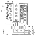
- the heater device 20 is installed in the room of a moving body such as a road traveling vehicle.
- the heater device 20 constitutes a part of the heating device for the room.
- the heater device 20 is an electric heater that generates heat by being supplied with power from a power source such as a battery or a generator mounted on a moving body.
- the heater device 20 is formed in a thin plate shape. The heater device 20 generates heat when electric power is supplied. As shown in FIG.
- the heater device 20 has a surface having a heat generating surface 24a that radiates radiant heat H mainly in a direction perpendicular to the surface in order to warm an object positioned in a direction perpendicular to the surface thereof. It can be called a state heater.
- the heater device 20 is installed indoors so as to radiate radiant heat H to the feet of the occupant 12.
- the heater device 20 can be used as a device for promptly providing warmth to the occupant 12 immediately after, for example, starting another heating device.
- the heater device 20 is installed on the wall surface of the room.
- the heater device 20 is installed so as to face the occupant 12 in the assumed normal posture.
- the road traveling vehicle has a steering column 14 for supporting the steering wheel 13.
- the heater device 20 is installed on the lower surface of the steering column 14 and the lower surface of the instrument panel cover 15 so as to face the occupant 12.
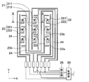
- the heater device 20 includes a first receiving electrode 21, a second receiving electrode 22, a transmitting electrode 23, a heat generating unit 24, an insulating base material 25, a cover member 26, a detecting unit 28, and a control unit. It has 29.
- the cover member 26 is omitted.
- the first receiving electrode 21 is shown by line hatching and the second receiving electrode 22 is shown by point hatching.
- the insulating base material 25 corresponds to a substrate.
- the insulating base material 25 is composed of a plate-shaped member extending along an XY plane defined by an axis X and an axis Y.
- the insulating base material 25 has a thickness in the direction of the axis Z.
- the insulating base material 25 is formed in a substantially quadrangular thin plate shape.
- the insulating base material 25 is made of a resin material having high insulating properties and withstanding high temperatures, for example, a polyimide film.
- the first receiving electrode 21, the second receiving electrode 22, the transmitting electrode 23, and the heat generating portion 24 are formed on the surface of the insulating base material 25 on the occupant side.
- the first receiving electrode 21, the second receiving electrode 22, the transmitting electrode 23, and the heat generating portion 24 are made of a thin copper film, and the heater device 20 is made thinner and has a lower heat capacity. Further, due to the reduced heat capacity, the temperature of the heat generating portion 24 rises rapidly due to energization. Further, when the object comes into contact with the heat generating surface 24a, the temperature of the contacted portion can be rapidly lowered. Further, the first receiving electrode 21, the second receiving electrode 22, and the transmitting electrode 23 are connected to the detection unit 28.
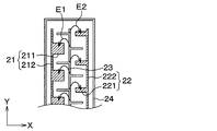
- the first receiving electrode 21 has a plurality of plate-shaped portions 211 formed so as to expand in the XY plane direction, and a connecting portion 212 connecting between the plate-shaped portions 211.
- the plurality of plate-shaped portions 211 each have a rectangular shape, and the connecting portion 212 has a linear shape.
- the second receiving electrode 22 has a plurality of plate-shaped portions 221 formed so as to expand in the XY plane direction, and a connecting portion 222 connecting between the plate-shaped portions 221.
- Each plate-shaped portion 221 has a rectangular shape
- the connecting portion 222 has a linear shape.
- each plate-shaped portion 211 of the first receiving electrode 21 has the same shape and area as each plate-shaped portion 221 of the second receiving electrode 22.
- the transmitting electrode 23 has a main line portion 231 and a plurality of branched portions 232 that branch off from the main line portion 231.
- the transmitting electrode 23 is arranged between the first receiving electrode 21 and the second receiving electrode 22 at a predetermined distance from the first receiving electrode 21 and the second receiving electrode 22.
- two branch-shaped portions 232 of the transmitting electrode 23 are arranged between the plate-shaped portions 211 of the first receiving electrodes 21 arranged side by side in the Y-axis direction. Further, one branch-shaped portion 232 of the transmitting electrode 23 is arranged between the plate-shaped portions 221 of the second receiving electrodes 22 arranged side by side in the Y-axis direction.
- the distance in the Y direction between the plate-shaped portion 211 of the first receiving electrode 21 and the branched portion 232 of the transmitting electrode 23 is the branch-shaped portion of the plate-shaped portion 221 of the second receiving electrode 22 and the transmitting electrode 23. It is shorter than the distance in the Y direction from 232.
- the capacitance formed between the transmitting electrode 23 and the first receiving electrode 21 is larger than the capacitance formed between the transmitting electrode 23 and the second receiving electrode 22. That is, the electric line of force E1 formed between the transmitting electrode 23 and the first receiving electrode 21 is larger than the electric line of force E2 formed between the transmitting electrode 23 and the second receiving electrode 22.
- the detection unit 28 of the present embodiment has a signal corresponding to a change in capacitance between the transmitting electrode 23 and the first receiving electrode 21, and a capacitance between the transmitting electrode 23 and the second receiving electrode 22.
- the signal corresponding to the change is amplified by the amplifier.
- the detection unit 28 detects whether or not the distance between the object around the heat generation unit 24 and the heat generation unit 24 is equal to or less than the first detection distance L1 with the first detection sensitivity. Further, the detection unit 28 determines whether or not the distance between the object around the heat generation unit 24 and the heat generation unit 24 is equal to or less than the second detection distance L2 with the second detection sensitivity lower than the first detection sensitivity. To detect.
- the detection unit 28 determines whether or not the distance between the object and the heat generating unit 24 is equal to or less than the second detection distance L2 and the signal indicating whether or not the distance between the object and the heat generating unit 24 is the first detection distance L1 or less. A signal indicating this is output to the control unit 29.
- the heat generating portion 24 has a linear shape and is formed so as to meander on one surface of the insulating base material 25.
- the heat generating unit 24 radiates radiant heat H that makes the occupant 12 feel warm by energizing from the control unit 29.
- the heat generating portion 24 is made of a material having a high thermal conductivity.
- the heat generating portion 24 can be configured by using a metal such as copper, an alloy of copper and tin (Cu—Sn), silver, tin, stainless steel, nickel, dichrome, and an alloy containing these.
- the cover member 26 protects the first receiving electrode 21, the second receiving electrode 22, the transmitting electrode 23, and the heat generating portion 24.
- the cover member 26 is composed of a first receiving electrode 21, a second receiving electrode 22, a transmitting electrode 23, and a low thermal conductive member having a lower thermal conductivity than the heat generating portion 24.
- the control unit 29 is configured as a computer equipped with a CPU, memory, I / O, etc., and the CPU executes various processes according to a program stored in the memory.
- Memory is a non-transitional substantive storage medium.
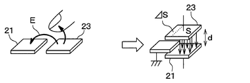
- the heater device 20 of this embodiment is configured as a mutual capacitance type capacitance sensor.
- the operating principle of the mutual capacitance type capacitance sensor will be described with reference to FIGS. 5 to 6.
- it will be described as a capacitance sensor having a transmitting electrode 23 and a first receiving electrode 21.
- the left side in FIG. 5 shows a schematic diagram of the transmitting electrode 23 and the first receiving electrode 21, and the right side in FIG. 5 shows the equivalent circuit of the transmitting electrode 23 and the first receiving electrode 21.
- the transmitting electrode 23 and the first receiving electrode 21 are arranged adjacent to each other. Then, when a voltage is applied between the transmitting electrode 23 and the first receiving electrode 21, an electric field is formed between the transmitting electrode 23 and the first receiving electrode 21.
- Equation 1 the dielectric constant between the transmitting electrode 23 and the first receiving electrode 21 is ⁇ , the area of each electrode is S, and the distance between the electrodes is d, the transmitting electrode 23 and the first receiving electrode 21 The capacitance C between them can be expressed as in Equation 1.
- Equation 2 the capacitance C between the transmitting electrode 23 and the first receiving electrode 21 can be expressed as in Equation 2.
- the proximity of the finger can be detected by determining the difference between the capacitance C shown in the formula 1 and the capacitance C'shown in the formula 2.
- the detection unit 28 detects whether or not the distance between the object around the heat generation unit 24 and the heat generation unit 24 is equal to or less than the first detection distance L1 with the first detection sensitivity. Further, the detection unit 28 determines whether or not the distance between the object around the heat generation unit 24 and the heat generation unit 24 is equal to or less than the second detection distance L2 with the second detection sensitivity lower than the first detection sensitivity. To detect.
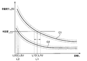
- FIG. 7 shows the relationship between the change C1 of the capacitance between the first receiving electrode 21 and the transmitting electrode 23 with respect to the distance L to the object in the heater device 20 of the present embodiment, and the second reception with respect to the distance L to the object.
- the relationship of the change C2 of the capacitance between the electrode 22 and the transmitting electrode 23 is shown.
- the change C1 of the capacitance between the first receiving electrode 21 and the transmitting electrode 23 is configured to be larger than the change C2 of the capacitance between the second receiving electrode 22 and the transmitting electrode 23. Has been done.
- the change in capacitance between the second receiving electrode 22 and the transmitting electrode 23 and the second receiving electrode 22 and the transmitting electrode 23 under the operating temperature environment varies depending on external factors such as temperature.
- the operating temperature environment means, for example, an environment of ⁇ 10 ° C. to 120 ° C.
- the lower limit value of the change in capacitance C1 between the first receiving electrode 21 and the transmitting electrode 23 is the capacitance between the second receiving electrode 22 and the transmitting electrode 23. It is configured to be larger than the upper limit of the change C2.
- the lower limit value L1D of the first detection distance L1 under the operating temperature environment is larger than the upper limit value L2U of the second detection distance L2 under the operating temperature environment.
- the lower limit of the first detection distance under the operating temperature environment is not smaller than the upper limit of the second detection distance under the operating temperature environment, and the proximity of the object is detected with high accuracy. ..
- control unit 29 determines in S100 whether or not the distance between the object around the heat generating unit 24 and the heat generating unit 24 is equal to or less than the first detection distance L1. Specifically, it is determined whether or not the distance between the object and the heat generating unit 24 is equal to or less than the first detection distance L1 based on the output signal of the detection unit 28.
- the control unit 29 when it is determined in S100 that the distance between the object around the heat generating unit 24 and the heat generating unit 24 is not equal to or less than the first detection distance L1, the control unit 29 together with the object and the heat generating unit 24 in S104. It is determined whether or not the distance of is equal to or less than the second detection distance L2. Specifically, it is determined whether or not the distance between the object and the heat generating unit 24 is equal to or less than the second detection distance L2 based on the output signal of the detection unit 28. Then, when it is determined that the distance between the object and the heat generating unit 24 is not equal to or less than the second detection distance L2, the control unit 29 ends this process. Therefore, the energization of the heat generating portion 24 is continued.
- control unit 29 sets the heater temperature of the heat generating unit 24 to the first in S102. Reduce to temperature. As a result, the temperature of the heat generating portion 24 is lowered.
- control unit 29 determines in S104 whether or not the distance between the object and the heat generating unit 24 is equal to or less than the second detection distance L2. Specifically, it is determined whether or not the distance between the object and the heat generating unit 24 is equal to or less than the second detection distance L2 based on the output signal of the detection unit 28.
- the control unit 29 stops the energization of the heat generating unit 24 and stops the operation of the heat generating unit 24 in S106. Let me. As a result, the temperature of the heat generating portion 24 is further lowered, and the thermal discomfort to the occupant can be reduced.
- the heater device 20 of the present embodiment includes a heat generating portion 24 that generates heat when energized.
- the detection unit 28 detects whether or not the distance between the object and the heat generating unit 24 is equal to or less than the first detection distance L1 with the first detection sensitivity, and the second detection sensitivity is lower than the first detection sensitivity. With the detection sensitivity, it is detected whether or not the distance between the object and the heat generating portion 24 is the second detection distance L2 or less, which is shorter than the first detection distance.
- the heater device 20 sets the heater temperature of the heat generating unit 24 to the first.
- a first temperature lowering unit (S102) for lowering the temperature to the above temperature is provided.
- the second temperature lowering unit that stops energization of the heat generating unit 24 is stopped. (S106) is provided. Therefore, it is possible to reduce the thermal discomfort to the occupant.
- the lower limit value L1D of the first detection distance L1 under the operating temperature environment is larger than the upper limit value L2U of the second detection distance L2 under the operating temperature environment. Therefore, the lower limit value L1D of the first detection distance L1 under the operating temperature environment is not smaller than the upper limit value L2U of the second detection distance L2 under the operating temperature environment, and the proximity of the object can be detected accurately. ..
- the heater device 20 includes receiving electrodes 21, 22 and transmitting electrodes 23. Then, the detection unit 28 detects whether or not the distance between the object and the heat generating unit 24 is equal to or less than the first detection distance L1 based on the change in capacitance between the receiving electrodes 21 and 22 and the transmitting electrode 23. To do. Further, it is determined whether or not the distance between the object around the heat generating portion 24 and the heat generating portion 24 is equal to or less than the second detection distance L2 based on the change in capacitance between the receiving electrodes 21 and 22 and the transmitting electrode 23. To detect.
- the distance between the object and the heat generating portion 24 can be detected based on the change in capacitance between the receiving electrodes 21 and 22 and the transmitting electrode 23.
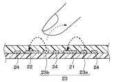
- the insulating base material 25 on which the heat generating portion 24, the receiving electrodes 21, 22 and the transmitting electrode 23 are formed is provided, and the heat generating portion 24, the receiving electrodes 21, 22 and the transmitting electrode 23 are formed on the same surface of the insulating base material 25. Has been done. Therefore, the structure can be simplified and the manufacturing cost can be reduced.
- the receiving electrodes 21 and 22 have a first receiving electrode 21 and a second receiving electrode 22.
- the distance between the object around the heat generation unit 24 and the heat generation unit 24 is equal to or less than the first detection distance L1 based on the change in capacitance between the first reception electrode 21 and the transmission electrode 23. Detects if there is. Further, it is determined whether or not the distance between the object around the heat generating portion 24 and the heat generating portion 24 is equal to or less than the second detection distance L2 based on the change in capacitance between the second receiving electrode 22 and the transmitting electrode 23. To detect.
- the transmitting electrode 23 also serves as the transmitting electrode of the first receiving electrode 21 and the transmitting electrode of the second receiving electrode 22, wiring can be greatly simplified.
- the heat generating portion 24 is formed so as to meander, and the first receiving electrode 21, the second receiving electrode 22, and the transmitting electrode 23 are arranged side by side between the heat generating portions 24.
- the distance between the object around the heat generating portion 24 and the heat generating portion 24 can be detected accurately. Can be done.
- the capacitance formed between the transmitting electrode 23 and the first receiving electrode 21 becomes larger than the capacitance formed between the transmitting electrode 23 and the second receiving electrode 22.
- the detection sensitivity of 1 is higher than that of the second detection sensitivity.
- the capacitance formed between the transmitting electrode 23 and the first receiving electrode 21 is made larger than the capacitance formed between the transmitting electrode 23 and the second receiving electrode 22.
- the first detection sensitivity can be made higher than the second detection sensitivity.
- the control unit 29 stops the operation of the heat generating unit 24 in S106.
- the control unit 29 sets the temperature of the heat generating unit 24 to a second temperature lower than the first temperature in S106. It may be lowered to.
- the heater device 20 according to the second embodiment will be described with reference to FIGS. 9 to 10.
- the heater device 20 of the first embodiment has a first receiving electrode 21, a second receiving electrode 22, and a transmitting electrode 23 as electrodes.
- the heater device 20 of the present embodiment has a first receiving electrode 21, a second receiving electrode 22, a first transmitting electrode 23a, and a second transmitting electrode 23b as electrodes.
- the distance between the object around the heat generation unit 24 and the heat generation unit 24 is the first detection distance L1 based on the change in capacitance between the first reception electrode 21 and the first transmission electrode 23a. Detects whether or not it is as follows. Further, whether or not the distance between the object around the heat generating portion 24 and the heat generating portion 24 is equal to or less than the second detection distance L2 based on the change in capacitance between the second receiving electrode 22 and the second transmitting electrode 23b. Is detected.
- the distance between the object around the heat generating portion 24 and the heat generating portion 24 is equal to or less than the first detection distance L1 based on the change in capacitance between the first receiving electrode 21 and the first transmitting electrode 23a. Whether or not it can be detected. Further, whether or not the distance between the object around the heat generating portion 24 and the heat generating portion 24 is equal to or less than the second detection distance L2 based on the change in capacitance between the second receiving electrode 22 and the second transmitting electrode 23b. Can also be detected.
- the same effect obtained from the configuration common to the first embodiment can be obtained in the same manner as in the first embodiment.
- the heat radiating plate 27 is formed on the same surface as the surface on which the first receiving electrode 21, the second receiving electrode 22, the transmitting electrode 23, and the heat generating portion 24 are formed in the insulating base material 25. ..
- the heat radiating plate 27 is made of the same thin copper film as the first receiving electrode 21, the second receiving electrode 22, the transmitting electrode 23, and the heat generating portion 24.
- the heat radiating plate 27 can promote heat dissipation from the heat generating portion 24.
- the same effect obtained from the configuration common to the first embodiment can be obtained in the same manner as in the first embodiment.
- the heater device 20 according to the fourth embodiment will be described with reference to FIG.
- the distance in the Y direction between the plate-shaped portion 211 of the first receiving electrode 21 and the branched portion 232 of the transmitting electrode 23 is the second. It is shorter than the distance in the Y direction between the plate-shaped portion 221 of the receiving electrode 22 and the branched portion 232 of the transmitting electrode 23.
- the capacitance formed between the transmitting electrode 23 and the first receiving electrode 21 is larger than the capacitance formed between the transmitting electrode 23 and the second receiving electrode 22.
- the area of the plate-shaped portion 211 of the first receiving electrode 21 is larger than the area of the plate-shaped portion 221 of the second receiving electrode 22.
- the capacitance formed between the transmitting electrode 23 and the first receiving electrode 21 is larger than the capacitance formed between the transmitting electrode 23 and the second receiving electrode 22.
- the first capacitance is formed by the capacitance formed between the transmitting electrode 23 and the first receiving electrode 21 and is larger than the capacitance formed between the transmitting electrode 23 and the second receiving electrode 22.
- the detection sensitivity is higher than the second detection sensitivity.
- the same effect obtained from the configuration common to the first embodiment can be obtained in the same manner as in the first embodiment.
- the distance in the Y direction between the plate-shaped portion 211 of the first receiving electrode 21 and the branched portion 232 of the transmitting electrode 23 is the same as that of the plate-shaped portion 221 of the second receiving electrode 22.
- the distance between the transmitting electrode 23 and the branch-shaped portion 232 in the Y direction is set to be shorter.
- the capacitance formed between the transmitting electrode 23 and the first receiving electrode 21 is made larger than the capacitance formed between the transmitting electrode 23 and the second receiving electrode 22. ..
- the capacitance formed between the transmitting electrode 23 and the first receiving electrode 21 so as to make the gain of the amplifier of the detection unit 28 different is between the transmitting electrode 23 and the second receiving electrode 22. It can also be considered to be larger than the capacitance formed in. In this way, the distance between the object around the heat generating portion 24 and the heat generating portion 24 may be detected with different detection sensitivities.
- control unit 29 controls the temperature of the heat generating unit 24 according to the output signal of the detection unit 28.
- control unit 29 can be configured as a device that outputs the output signal of the detection unit 28 without controlling the temperature of the heat generating unit 24 according to the output signal of the detection unit 28.
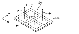
- one heat generating surface 24a is formed on one insulating base material 25, but as shown in FIG. 13, a plurality of heat generating surfaces 24a are dispersed and formed on one insulating base material 25. You can also do it. That is, the heater device has a plurality of heat generating surfaces 24a that radiate radiant heat by the heat generated by the heat generating unit 24, and the plurality of heat generating surfaces 24a can be dispersed and arranged on the insulating base material 25.
- the heater device includes a heat generating portion that generates heat when energized. Further, the first detection sensitivity detects whether or not the distance between the object around the heat generating portion and the heat generating portion is equal to or less than the first detection distance, and the second detection sensitivity is lower than the first detection sensitivity. It is provided with a detection unit that detects whether or not the distance between the object around the heat generation unit and the heat generation unit is equal to or less than the second detection distance, which is shorter than the first detection distance.
- the heater device 20 determines the heater temperature of the heat generating portion. Is provided with a first temperature lowering portion that lowers the temperature to the first temperature.
- the heater temperature of the heat generating unit is lowered to a second temperature lower than the first temperature. It is provided with a second temperature lowering part for causing the heat to be lowered. Therefore, it is possible to reduce the thermal discomfort to the occupant.
- the detection unit detects that the distance between the object around the heat generating portion and the heat generating portion is equal to or less than the second detection distance, the second temperature lowering portion moves to the heat generating portion. Stop energizing. Therefore, it is possible to reduce the thermal discomfort to the occupant.
- the lower limit of the first detection distance under the operating temperature environment is larger than the upper limit of the second detection distance under the operating temperature environment.
- the lower limit of the first detection distance under the operating temperature environment is not smaller than the upper limit of the second detection distance under the operating temperature environment, and the proximity of the object can be detected accurately.
- the heater device includes a receiving electrode and a transmitting electrode. Further, the detection unit detects whether or not the distance between the object around the heat generating portion and the heat generating portion is equal to or less than the first detection distance based on the change in capacitance between the receiving electrode and the transmitting electrode. Further, it is detected whether or not the distance between the object around the heat generating portion and the heat generating portion is equal to or less than the second detection distance based on the change in the capacitance between the receiving electrode and the transmitting electrode.
- the heater device includes a substrate on which a heat generating portion, a receiving electrode, and a transmitting electrode are formed.
- the heat generating portion, the receiving electrode, and the transmitting electrode are formed on the same surface of the substrate. Therefore, the structure can be simplified and the manufacturing cost can be reduced.
- the receiving electrode has a first receiving electrode and a second receiving electrode.
- the detection unit detects whether or not the distance between the object around the heat generating portion and the heat generating portion is equal to or less than the first detection distance based on the change in capacitance between the first receiving electrode and the transmitting electrode. To do. Further, it is detected whether or not the distance between the object around the heat generating portion and the heat generating portion is equal to or less than the second detection distance based on the change in the capacitance between the second receiving electrode and the transmitting electrode.
- the transmitting electrode also serves as the transmitting electrode of the first receiving electrode and the transmitting electrode of the second receiving electrode, the wiring can be greatly simplified.
- the heat generating portion is formed so as to meander, and the first receiving electrode, the second receiving electrode, and the transmitting electrode are arranged side by side between the heat generating portions.
- the first receiving electrode, the second receiving electrode, and the transmitting electrode are arranged so as to be aligned with the heat generating portion, the distance between the object around the heat generating portion and the heat generating portion can be detected accurately.
- the capacitance formed between the transmitting electrode and the first receiving electrode is larger than the capacitance formed between the transmitting electrode and the second receiving electrode.
- the first detection sensitivity is higher than the second detection sensitivity.
- the capacitance formed between the transmitting electrode and the first receiving electrode is made larger than the capacitance formed between the transmitting electrode and the second receiving electrode.
- the first detection sensitivity can be made higher than the second detection sensitivity.
- the tenth viewpoint has a plurality of heat generating surfaces that radiate radiant heat by the heat generated by the heat generating portion, and the plurality of heat generating surfaces are dispersedly arranged on the substrate.
- the heater device has a plurality of heat generating surfaces that radiate radiant heat by the heat generated by the heat generating portion, and the plurality of heat generating surfaces can be dispersed and arranged on the substrate.
- the process of S102 corresponds to the first temperature drop section
- the process of S106 corresponds to the second temperature drop section.
Abstract
This heater device is provided with: a heating unit (24) that generates heat by conduction; and a detecting unit (28) that detects, with a first detection sensibility, whether the distance between the heating unit and an object in the vicinity of the heating unit is no greater than a first detection distance (L1), and that detects, with a second sensibility lower than the first sensibility, whether the distance between the heating unit and an object in the vicinity of the heating unit is no greater than a second detection distance (L2) which is shorter than the first detection distance.
Description
本出願は、2019年3月26日に出願された日本特許出願番号2019-58595号に基づくもので、ここにその記載内容が参照により組み入れられる。
This application is based on Japanese Patent Application No. 2019-58595 filed on March 26, 2019, the contents of which are incorporated herein by reference.
本開示は、ヒータ装置に関するものである。
This disclosure relates to a heater device.
従来、特許文献1に記載された装置がある。この装置は、通電によって発熱する発熱部と、発熱部の周囲の物体による静電容量の変化を検出するための複数の電極と、複数の電極間の静電容量の変化に基づいて物体の近接を検出する近接検出部と、近接検出部により検出された物体の近接に基づいて発熱部への通電を制御する通電制御部と、を備えている。
Conventionally, there is a device described in Patent Document 1. This device has a heat generating part that generates heat when energized, a plurality of electrodes for detecting a change in capacitance due to an object around the heat generating part, and an object close to each other based on the change in capacitance between the plurality of electrodes. It is provided with a proximity detection unit for detecting the above and an energization control unit for controlling energization to the heat generating unit based on the proximity of the object detected by the proximity detection unit.
上記特許文献1に記載されたような装置は、発熱部への通電によって複数の電極間の静電容量が変化する。また、発明者の検討によれば、発熱部の発熱に伴う各電極の熱収縮によっても複数の電極間の静電容量が変化することが分かった。また、発明者の検討によれば、このように外的要因によって電極間の静電容量が変化すると、物体の近接を検出できない場合がある。
本開示は、外的要因によって電極間の静電容量が変化しても発熱部の周囲の物体の近接をより精度よく検出できるようにすることを目的とする。 In a device as described in Patent Document 1, the capacitance between a plurality of electrodes changes depending on the energization of the heat generating portion. Further, according to the study of the inventor, it was found that the capacitance between the plurality of electrodes also changes due to the heat shrinkage of each electrode due to the heat generation of the heat generating portion. Further, according to the study of the inventor, if the capacitance between the electrodes changes due to such an external factor, the proximity of the object may not be detected.
An object of the present disclosure is to enable more accurate detection of the proximity of an object around a heat generating portion even if the capacitance between electrodes changes due to an external factor.
本開示の1つの観点によれば、ヒータ装置は、通電によって発熱する発熱部と、第1の検出感度で発熱部の周囲の物体と発熱部との距離が第1検知距離以下であるか否かを検出するとともに第1の検出感度よりも感度の低い第2の検出感度で発熱部の周囲の物体と発熱部との距離が第1検知距離より短い第2検知距離以下であるか否かを検出する検出部と、を備えている。
According to one aspect of the present disclosure, in the heater device, whether or not the distance between the heat generating portion that generates heat by energization and the object around the heat generating portion and the heat generating portion with the first detection sensitivity is equal to or less than the first detection distance. Whether or not the distance between the object around the heat generating portion and the heat generating portion is shorter than the first detection distance and equal to or less than the second detection distance with the second detection sensitivity, which is lower than the first detection sensitivity. It is provided with a detection unit for detecting.
したがって、外的要因によって電極間の静電容量が変化しても発熱部の周囲の物体の近接をより精度よく検出することができる。
Therefore, even if the capacitance between the electrodes changes due to an external factor, the proximity of objects around the heat generating portion can be detected more accurately.
なお、各構成要素等に付された括弧付きの参照符号は、その構成要素等と後述する実施形態に記載の具体的な構成要素等との対応関係の一例を示すものである。
Note that the reference reference numerals in parentheses attached to each component or the like indicate an example of the correspondence between the component or the like and the specific component or the like described in the embodiment described later.
以下、実施形態について図に基づいて説明する。なお、以下の各実施形態相互において、互いに同一もしくは均等である部分には、図中、同一符号を付してある。
Hereinafter, the embodiment will be described with reference to the figure. In each of the following embodiments, the same or equal parts are designated by the same reference numerals in the drawings.
(第1実施形態)
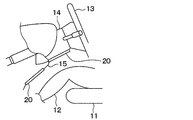
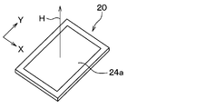
第1実施形態のヒータ装置について、図1~図8を用いて説明する。図1に示すように、ヒータ装置20は、道路走行車両などの移動体の室内に設置されている。ヒータ装置20は、室内のための暖房装置の一部を構成している。ヒータ装置20は、移動体に搭載された電池、発電機などの電源から給電されて発熱する電気的なヒータである。ヒータ装置20は、薄い板状に形成されている。ヒータ装置20は、電力が供給されると発熱する。図2に示すように、ヒータ装置20は、その表面と垂直な方向に位置付けられた対象物を暖めるために、主としてその表面と垂直な方向へ向けて輻射熱Hを放射する発熱面24aを有する面状ヒータと呼ぶことができる。 (First Embodiment)
The heater device of the first embodiment will be described with reference to FIGS. 1 to 8. As shown in FIG. 1, theheater device 20 is installed in the room of a moving body such as a road traveling vehicle. The heater device 20 constitutes a part of the heating device for the room. The heater device 20 is an electric heater that generates heat by being supplied with power from a power source such as a battery or a generator mounted on a moving body. The heater device 20 is formed in a thin plate shape. The heater device 20 generates heat when electric power is supplied. As shown in FIG. 2, the heater device 20 has a surface having a heat generating surface 24a that radiates radiant heat H mainly in a direction perpendicular to the surface in order to warm an object positioned in a direction perpendicular to the surface thereof. It can be called a state heater.
第1実施形態のヒータ装置について、図1~図8を用いて説明する。図1に示すように、ヒータ装置20は、道路走行車両などの移動体の室内に設置されている。ヒータ装置20は、室内のための暖房装置の一部を構成している。ヒータ装置20は、移動体に搭載された電池、発電機などの電源から給電されて発熱する電気的なヒータである。ヒータ装置20は、薄い板状に形成されている。ヒータ装置20は、電力が供給されると発熱する。図2に示すように、ヒータ装置20は、その表面と垂直な方向に位置付けられた対象物を暖めるために、主としてその表面と垂直な方向へ向けて輻射熱Hを放射する発熱面24aを有する面状ヒータと呼ぶことができる。 (First Embodiment)
The heater device of the first embodiment will be described with reference to FIGS. 1 to 8. As shown in FIG. 1, the
室内には、乗員12が着座するための座席11が設置されている。ヒータ装置20は、乗員12の足元に輻射熱Hを放射するように室内に設置されている。ヒータ装置20は、たとえば他の暖房装置の起動直後において、乗員12に対して即効的に暖かさを提供するための装置として利用することができる。ヒータ装置20は、室内の壁面に設置される。ヒータ装置20は、想定される通常の姿勢の乗員12に対向するように設置される。道路走行車両は、ハンドル13を支持するためのステアリングコラム14を有している。ヒータ装置20は、ステアリングコラム14の下面と、インパネカバー15の下面に、それぞれ乗員12に対向するように設置されている。
In the room, a seat 11 for the occupant 12 to sit is installed. The heater device 20 is installed indoors so as to radiate radiant heat H to the feet of the occupant 12. The heater device 20 can be used as a device for promptly providing warmth to the occupant 12 immediately after, for example, starting another heating device. The heater device 20 is installed on the wall surface of the room. The heater device 20 is installed so as to face the occupant 12 in the assumed normal posture. The road traveling vehicle has a steering column 14 for supporting the steering wheel 13. The heater device 20 is installed on the lower surface of the steering column 14 and the lower surface of the instrument panel cover 15 so as to face the occupant 12.
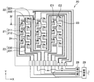
次に、ヒータ装置20の構成について説明する。図3~図4に示すように、ヒータ装置20は、第1受信電極21、第2受信電極22、発信電極23、発熱部24、絶縁基材25、カバー部材26、検出部28および制御部29を備えている。なお、図3では、カバー部材26を省略してある。また、図3では、図示の明確化のために、第1受信電極21を線ハッチングで示すとともに第2受信電極22を点ハッチングで示してある。また、絶縁基材25は基板に相当する。
Next, the configuration of the heater device 20 will be described. As shown in FIGS. 3 to 4, the heater device 20 includes a first receiving electrode 21, a second receiving electrode 22, a transmitting electrode 23, a heat generating unit 24, an insulating base material 25, a cover member 26, a detecting unit 28, and a control unit. It has 29. In FIG. 3, the cover member 26 is omitted. Further, in FIG. 3, for clarity of illustration, the first receiving electrode 21 is shown by line hatching and the second receiving electrode 22 is shown by point hatching. Further, the insulating base material 25 corresponds to a substrate.
絶縁基材25は、軸Xと軸Yによって規定されるX-Y平面に沿って広がる板状部材によって構成されている。絶縁基材25は、軸Zの方向に厚さをもつ。絶縁基材25は、ほぼ四角形の薄い板状に形成されている。絶縁基材25は、高い絶縁性を有し、かつ、高温に耐える樹脂材料、例えば、ポリイミドフィルムによって構成されている。絶縁基材25における乗員側の面に、第1受信電極21、第2受信電極22、発信電極23および発熱部24が形成されている。
The insulating base material 25 is composed of a plate-shaped member extending along an XY plane defined by an axis X and an axis Y. The insulating base material 25 has a thickness in the direction of the axis Z. The insulating base material 25 is formed in a substantially quadrangular thin plate shape. The insulating base material 25 is made of a resin material having high insulating properties and withstanding high temperatures, for example, a polyimide film. The first receiving electrode 21, the second receiving electrode 22, the transmitting electrode 23, and the heat generating portion 24 are formed on the surface of the insulating base material 25 on the occupant side.
第1受信電極21、第2受信電極22、発信電極23および発熱部24は、薄銅膜によって構成されており、ヒータ装置20の薄型化および低熱容量化を実現している。また、低熱容量化によって、通電により発熱部24の温度は迅速に上昇する。また、物体が発熱面24aに接触した際に、接触した部分の温度を迅速に低下させることができる。また、第1受信電極21、第2受信電極22および発信電極23は、検出部28に接続されている。
The first receiving electrode 21, the second receiving electrode 22, the transmitting electrode 23, and the heat generating portion 24 are made of a thin copper film, and the heater device 20 is made thinner and has a lower heat capacity. Further, due to the reduced heat capacity, the temperature of the heat generating portion 24 rises rapidly due to energization. Further, when the object comes into contact with the heat generating surface 24a, the temperature of the contacted portion can be rapidly lowered. Further, the first receiving electrode 21, the second receiving electrode 22, and the transmitting electrode 23 are connected to the detection unit 28.
第1受信電極21は、X-Y平面方向に拡がるように形成された複数の板状部211と、各板状部211の間を接続する接続部212を有している。複数の板状部211は、それぞれ矩形形状を成しており、接続部212は線状を成している。
The first receiving electrode 21 has a plurality of plate-shaped portions 211 formed so as to expand in the XY plane direction, and a connecting portion 212 connecting between the plate-shaped portions 211. The plurality of plate-shaped portions 211 each have a rectangular shape, and the connecting portion 212 has a linear shape.
第2受信電極22は、X-Y平面方向に拡がるように形成された複数の板状部221と、各板状部221の間を接続する接続部222を有している。各板状部221は、矩形形状を成しており、接続部222は線状を成している。また、第1受信電極21の各板状部211は、第2受信電極22の各板状部221と形状および面積が同じになっている。
The second receiving electrode 22 has a plurality of plate-shaped portions 221 formed so as to expand in the XY plane direction, and a connecting portion 222 connecting between the plate-shaped portions 221. Each plate-shaped portion 221 has a rectangular shape, and the connecting portion 222 has a linear shape. Further, each plate-shaped portion 211 of the first receiving electrode 21 has the same shape and area as each plate-shaped portion 221 of the second receiving electrode 22.
発信電極23は、主線部231と、この主線部231から分岐して延びる複数の枝状部232を有している。発信電極23は、第1受信電極21と第2受信電極22の間に、第1受信電極21と第2受信電極22と所定間隔を空けて配置されている。
The transmitting electrode 23 has a main line portion 231 and a plurality of branched portions 232 that branch off from the main line portion 231. The transmitting electrode 23 is arranged between the first receiving electrode 21 and the second receiving electrode 22 at a predetermined distance from the first receiving electrode 21 and the second receiving electrode 22.
本実施形態のヒータ装置20においては、Y軸方向に並んで配置された第1受信電極21の板状部211の間に、発信電極23の枝状部232が2つ配置されている。また、Y軸方向に並んで配置された第2受信電極22の板状部221の間に、発信電極23の枝状部232が1つ配置されている。
In the heater device 20 of the present embodiment, two branch-shaped portions 232 of the transmitting electrode 23 are arranged between the plate-shaped portions 211 of the first receiving electrodes 21 arranged side by side in the Y-axis direction. Further, one branch-shaped portion 232 of the transmitting electrode 23 is arranged between the plate-shaped portions 221 of the second receiving electrodes 22 arranged side by side in the Y-axis direction.
これにより、第1受信電極21の板状部211と発信電極23の枝状部232との間のY方向の距離は、第2受信電極22の板状部221と発信電極23の枝状部232との間のY方向の距離よりも短くなっている。
As a result, the distance in the Y direction between the plate-shaped portion 211 of the first receiving electrode 21 and the branched portion 232 of the transmitting electrode 23 is the branch-shaped portion of the plate-shaped portion 221 of the second receiving electrode 22 and the transmitting electrode 23. It is shorter than the distance in the Y direction from 232.
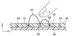
このため、発信電極23と第1受信電極21との間に形成される静電容量が、発信電極23と第2受信電極22との間に形成される静電容量よりも大きくなる。すなわち、発信電極23と第1受信電極21の間に形成される電気力線E1の方が、発信電極23と第2受信電極22の間に形成される電気力線E2よりも大きくなる。
Therefore, the capacitance formed between the transmitting electrode 23 and the first receiving electrode 21 is larger than the capacitance formed between the transmitting electrode 23 and the second receiving electrode 22. That is, the electric line of force E1 formed between the transmitting electrode 23 and the first receiving electrode 21 is larger than the electric line of force E2 formed between the transmitting electrode 23 and the second receiving electrode 22.
本実施形態の検出部28は、発信電極23と第1受信電極21との間の静電容量の変化に応じた信号と、発信電極23と第2受信電極22との間の静電容量の変化に応じた信号を増幅器で増幅する。また、検出部28は、第1の検出感度で発熱部24の周囲の物体と発熱部24との距離が第1検知距離L1以下であるか否かを検出する。さらに、検出部28は、第1の検出感度よりも感度の低い第2の検出感度で発熱部24の周囲の物体と発熱部24との距離が第2検知距離L2以下であるか否かを検出する。
The detection unit 28 of the present embodiment has a signal corresponding to a change in capacitance between the transmitting electrode 23 and the first receiving electrode 21, and a capacitance between the transmitting electrode 23 and the second receiving electrode 22. The signal corresponding to the change is amplified by the amplifier. Further, the detection unit 28 detects whether or not the distance between the object around the heat generation unit 24 and the heat generation unit 24 is equal to or less than the first detection distance L1 with the first detection sensitivity. Further, the detection unit 28 determines whether or not the distance between the object around the heat generation unit 24 and the heat generation unit 24 is equal to or less than the second detection distance L2 with the second detection sensitivity lower than the first detection sensitivity. To detect.
そして、検出部28は、物体と発熱部24との距離が第1検知距離L1以下であるか否かを示す信号と物体と発熱部24との距離が第2検知距離L2以下であるか否かを示す信号を制御部29に出力する。
Then, the detection unit 28 determines whether or not the distance between the object and the heat generating unit 24 is equal to or less than the second detection distance L2 and the signal indicating whether or not the distance between the object and the heat generating unit 24 is the first detection distance L1 or less. A signal indicating this is output to the control unit 29.
発熱部24は、線状を成しており、絶縁基材25の一面に蛇行するように形成されている。発熱部24は、制御部29からの通電によって乗員12に暖かさを感じさせる輻射熱Hを放射する。発熱部24は、高い熱伝導率を有する材料によって作られている。発熱部24は、銅、銅とスズとの合金(Cu-Sn)、銀、スズ、ステンレス鋼、ニッケル、ニクロムなどの金属およびこれらを含む合金を用いて構成することができる。
The heat generating portion 24 has a linear shape and is formed so as to meander on one surface of the insulating base material 25. The heat generating unit 24 radiates radiant heat H that makes the occupant 12 feel warm by energizing from the control unit 29. The heat generating portion 24 is made of a material having a high thermal conductivity. The heat generating portion 24 can be configured by using a metal such as copper, an alloy of copper and tin (Cu—Sn), silver, tin, stainless steel, nickel, dichrome, and an alloy containing these.
カバー部材26は、第1受信電極21、第2受信電極22、発信電極23および発熱部24を保護するものである。カバー部材26は、第1受信電極21、第2受信電極22、発信電極23および発熱部24よりも熱伝導率の低い低熱伝導部材によって構成されている。
The cover member 26 protects the first receiving electrode 21, the second receiving electrode 22, the transmitting electrode 23, and the heat generating portion 24. The cover member 26 is composed of a first receiving electrode 21, a second receiving electrode 22, a transmitting electrode 23, and a low thermal conductive member having a lower thermal conductivity than the heat generating portion 24.
制御部29は、CPU、メモリ、I/O等を備えたコンピュータとして構成されており、CPUは、メモリに記憶されたプログラムに従って各種処理を実施する。メモリは、非遷移的実体的記憶媒体である。
The control unit 29 is configured as a computer equipped with a CPU, memory, I / O, etc., and the CPU executes various processes according to a program stored in the memory. Memory is a non-transitional substantive storage medium.
本実施形態のヒータ装置20は、相互容量方式静電容量センサとして構成されている。次に、相互容量方式静電容量センサの作動原理について図5~図6を参照して説明する。ここでは、発信電極23と第1受信電極21を有する静電容量センサとして説明する。
The heater device 20 of this embodiment is configured as a mutual capacitance type capacitance sensor. Next, the operating principle of the mutual capacitance type capacitance sensor will be described with reference to FIGS. 5 to 6. Here, it will be described as a capacitance sensor having a transmitting electrode 23 and a first receiving electrode 21.
図5中の左側は、発信電極23と第1受信電極21の模式図を表しており、図5中の右側は、発信電極23と第1受信電極21の等価回路を表している。
The left side in FIG. 5 shows a schematic diagram of the transmitting electrode 23 and the first receiving electrode 21, and the right side in FIG. 5 shows the equivalent circuit of the transmitting electrode 23 and the first receiving electrode 21.
図5中の左側に示すように、相互容量方式静電容量センサでは、発信電極23と第1受信電極21とが隣接して配置される。そして、発信電極23と第1受信電極21の間に電圧を印加すると、発信電極23と第1受信電極21のとの間に電界が形成される。
As shown on the left side in FIG. 5, in the mutual capacitance type capacitance sensor, the transmitting electrode 23 and the first receiving electrode 21 are arranged adjacent to each other. Then, when a voltage is applied between the transmitting electrode 23 and the first receiving electrode 21, an electric field is formed between the transmitting electrode 23 and the first receiving electrode 21.
ここで、発信電極23と第1受信電極21のとの間の誘電率をε、各電極の面積をS、各電極の間隔をdとすると、発信電極23と第1受信電極21のとの間の静電容量Cは、数式1のように表すことができる。
Here, assuming that the dielectric constant between the transmitting electrode 23 and the first receiving electrode 21 is ε, the area of each electrode is S, and the distance between the electrodes is d, the transmitting electrode 23 and the first receiving electrode 21 The capacitance C between them can be expressed as in Equation 1.

この場合、各電極と接地された物体の重複する面積をΔSとすると、発信電極23と第1受信電極21の間の静電容量Cは、数式2のように表すことができる。
In this case, assuming that the overlapping area of each electrode and the grounded object is ΔS, the capacitance C between the transmitting electrode 23 and the first receiving electrode 21 can be expressed as in Equation 2.

前述したように、検出部28は、第1の検出感度で発熱部24の周囲の物体と発熱部24との距離が第1検知距離L1以下であるか否かを検出する。さらに、検出部28は、第1の検出感度よりも感度の低い第2の検出感度で発熱部24の周囲の物体と発熱部24との距離が第2検知距離L2以下であるか否かを検出する。
As described above, the detection unit 28 detects whether or not the distance between the object around the heat generation unit 24 and the heat generation unit 24 is equal to or less than the first detection distance L1 with the first detection sensitivity. Further, the detection unit 28 determines whether or not the distance between the object around the heat generation unit 24 and the heat generation unit 24 is equal to or less than the second detection distance L2 with the second detection sensitivity lower than the first detection sensitivity. To detect.
図7は、本実施形態のヒータ装置20における物体との距離Lに対する第1受信電極21および発信電極23との間の静電容量の変化C1の関係と、物体との距離Lに対する第2受信電極22および発信電極23との間の静電容量の変化C2の関係を示している。
FIG. 7 shows the relationship between the change C1 of the capacitance between the first receiving electrode 21 and the transmitting electrode 23 with respect to the distance L to the object in the heater device 20 of the present embodiment, and the second reception with respect to the distance L to the object. The relationship of the change C2 of the capacitance between the electrode 22 and the transmitting electrode 23 is shown.
物体との距離Lが短くなるほど、各静電容量の変化C1、C2は大きくなる。また、第1受信電極21および発信電極23との間の静電容量の変化C1の方が、第2受信電極22および発信電極23との間の静電容量の変化C2よりも大きくなるよう構成されている。
The shorter the distance L to the object, the larger the changes C1 and C2 of each capacitance. Further, the change C1 of the capacitance between the first receiving electrode 21 and the transmitting electrode 23 is configured to be larger than the change C2 of the capacitance between the second receiving electrode 22 and the transmitting electrode 23. Has been done.
ここで、図7中の点線で示すように、使用温度環境下において、第2受信電極22と発信電極23との間の静電容量の変化C1および第2受信電極22と発信電極23との間の静電容量の変化C2は、温度等の外的要因によって変動する。ここで、使用温度環境下とは、例えば-10℃~120℃の環境下をいう。
Here, as shown by the dotted line in FIG. 7, the change in capacitance between the second receiving electrode 22 and the transmitting electrode 23 and the second receiving electrode 22 and the transmitting electrode 23 under the operating temperature environment. The change in capacitance C2 between them varies depending on external factors such as temperature. Here, the operating temperature environment means, for example, an environment of −10 ° C. to 120 ° C.
本実施形態のヒータ装置20は、第1受信電極21および発信電極23との間の静電容量の変化C1の下限値が、第2受信電極22および発信電極23との間の静電容量の変化C2の上限値よりも大きくなるよう構成されている。
In the heater device 20 of the present embodiment, the lower limit value of the change in capacitance C1 between the first receiving electrode 21 and the transmitting electrode 23 is the capacitance between the second receiving electrode 22 and the transmitting electrode 23. It is configured to be larger than the upper limit of the change C2.
また、本実施形態のヒータ装置20は、使用温度環境下における第1検知距離L1の下限値L1Dが、使用温度環境下における第2検知距離L2の上限値L2Uよりも大きくなっている。
Further, in the heater device 20 of the present embodiment, the lower limit value L1D of the first detection distance L1 under the operating temperature environment is larger than the upper limit value L2U of the second detection distance L2 under the operating temperature environment.
このため、使用温度環境下における第1検知距離の下限値が、使用温度環境下における第2検知距離の上限値より小さくなることがなく、精度よく物体の近接が検出されるようになっている。
Therefore, the lower limit of the first detection distance under the operating temperature environment is not smaller than the upper limit of the second detection distance under the operating temperature environment, and the proximity of the object is detected with high accuracy. ..
次に、制御部29の処理について図8のフローチャートを参照して説明する。この処理は、ヒータ装置20の電源がオンされると同時に開始される。ヒータ装置20の電源がオンされると、制御部29は発熱部24に通電する。これにより、発熱部24は発熱する。また、検出部28は発熱部24に所定の電圧を印加する。
Next, the processing of the control unit 29 will be described with reference to the flowchart of FIG. This process is started as soon as the power of the heater device 20 is turned on. When the power of the heater device 20 is turned on, the control unit 29 energizes the heat generating unit 24. As a result, the heat generating portion 24 generates heat. Further, the detection unit 28 applies a predetermined voltage to the heat generation unit 24.
まず、制御部29は、S100にて、発熱部24の周囲の物体と発熱部24との距離が第1検知距離L1以下であるか否かを判定する。具体的には、検出部28の出力信号に基づいて物体と発熱部24との距離が第1検知距離L1以下であるか否かを判定する。
First, the control unit 29 determines in S100 whether or not the distance between the object around the heat generating unit 24 and the heat generating unit 24 is equal to or less than the first detection distance L1. Specifically, it is determined whether or not the distance between the object and the heat generating unit 24 is equal to or less than the first detection distance L1 based on the output signal of the detection unit 28.
ここで、S100にて、発熱部24の周囲の物体と発熱部24との距離が第1検知距離L1以下でないと判定された場合、制御部29は、S104にて、物体と発熱部24との距離が第2検知距離L2以下であるか否かを判定する。具体的には、検出部28の出力信号に基づいて物体と発熱部24との距離が第2検知距離L2以下であるか否かを判定する。そして、物体と発熱部24との距離が第2検知距離L2以下でないと判定された場合、制御部29は、本処理を終了する。したがって、発熱部24への通電が継続される。
Here, when it is determined in S100 that the distance between the object around the heat generating unit 24 and the heat generating unit 24 is not equal to or less than the first detection distance L1, the control unit 29 together with the object and the heat generating unit 24 in S104. It is determined whether or not the distance of is equal to or less than the second detection distance L2. Specifically, it is determined whether or not the distance between the object and the heat generating unit 24 is equal to or less than the second detection distance L2 based on the output signal of the detection unit 28. Then, when it is determined that the distance between the object and the heat generating unit 24 is not equal to or less than the second detection distance L2, the control unit 29 ends this process. Therefore, the energization of the heat generating portion 24 is continued.
また、S100にて、物体と発熱部24との距離が第1検知距離L1以下となっていると判定された場合、制御部29は、S102にて、発熱部24のヒータ温度を第1の温度に低下させる。これにより、発熱部24の温度は低下する。
Further, when it is determined in S100 that the distance between the object and the heat generating unit 24 is equal to or less than the first detection distance L1, the control unit 29 sets the heater temperature of the heat generating unit 24 to the first in S102. Reduce to temperature. As a result, the temperature of the heat generating portion 24 is lowered.
次に、制御部29は、S104にて、物体と発熱部24との距離が第2検知距離L2以下であるか否かを判定する。具体的には、検出部28の出力信号に基づいて物体と発熱部24との距離が第2検知距離L2以下であるか否かを判定する。
Next, the control unit 29 determines in S104 whether or not the distance between the object and the heat generating unit 24 is equal to or less than the second detection distance L2. Specifically, it is determined whether or not the distance between the object and the heat generating unit 24 is equal to or less than the second detection distance L2 based on the output signal of the detection unit 28.
ここで、物体と発熱部24との距離が第2検知距離L2以下となっている場合、制御部29は、S106にて、発熱部24への通電を停止して発熱部24の動作を停止させる。これにより、さらに、発熱部24の温度は低下し、乗員のへの熱的な不快感を低減することができる。
Here, when the distance between the object and the heat generating unit 24 is equal to or less than the second detection distance L2, the control unit 29 stops the energization of the heat generating unit 24 and stops the operation of the heat generating unit 24 in S106. Let me. As a result, the temperature of the heat generating portion 24 is further lowered, and the thermal discomfort to the occupant can be reduced.
以上、説明したように、本実施形態のヒータ装置20は、通電によって発熱する発熱部24を備えている。また、検出部28は、第1の検出感度で物体と発熱部24との距離が第1検知距離L1以下であるか否かを検出し、第1の検出感度よりも感度の低い第2の検出感度で物体と発熱部24との距離が第1検知距離より短い第2検知距離L2以下であるか否かを検出する。
As described above, the heater device 20 of the present embodiment includes a heat generating portion 24 that generates heat when energized. Further, the detection unit 28 detects whether or not the distance between the object and the heat generating unit 24 is equal to or less than the first detection distance L1 with the first detection sensitivity, and the second detection sensitivity is lower than the first detection sensitivity. With the detection sensitivity, it is detected whether or not the distance between the object and the heat generating portion 24 is the second detection distance L2 or less, which is shorter than the first detection distance.
したがって、外的要因によって電極間の静電容量が変化しても発熱部の周囲の物体の近接をより精度よく検出することができる。
Therefore, even if the capacitance between the electrodes changes due to an external factor, the proximity of objects around the heat generating portion can be detected more accurately.
また、ヒータ装置20は、検出部28により発熱部24の周囲の物体と発熱部24との距離が第1検知距離L1以下であることが検出された場合、発熱部24のヒータ温度を第1の温度に低下させる第1温度低下部(S102)を備えている。さらに、検出部28により発熱部24の周囲の物体と発熱部24との距離が第2検知距離L2以下であることが検出された場合、発熱部24への通電を停止する第2温度低下部(S106)を備えている。したがって、乗員への熱的な不快感を低減することができる。
Further, when the detection unit 28 detects that the distance between the object around the heat generating unit 24 and the heat generating unit 24 is equal to or less than the first detection distance L1, the heater device 20 sets the heater temperature of the heat generating unit 24 to the first. A first temperature lowering unit (S102) for lowering the temperature to the above temperature is provided. Further, when the detection unit 28 detects that the distance between the object around the heat generating unit 24 and the heat generating unit 24 is equal to or less than the second detection distance L2, the second temperature lowering unit that stops energization of the heat generating unit 24 is stopped. (S106) is provided. Therefore, it is possible to reduce the thermal discomfort to the occupant.
また、使用温度環境下における第1検知距離L1の下限値L1Dが、使用温度環境下における第2検知距離L2の上限値L2Uよりも大きくなっている。したがって、使用温度環境下における第1検知距離L1の下限値L1Dが、使用温度環境下における第2検知距離L2の上限値L2Uより小さくなることがなく、精度よく物体の近接を検出することができる。
Further, the lower limit value L1D of the first detection distance L1 under the operating temperature environment is larger than the upper limit value L2U of the second detection distance L2 under the operating temperature environment. Therefore, the lower limit value L1D of the first detection distance L1 under the operating temperature environment is not smaller than the upper limit value L2U of the second detection distance L2 under the operating temperature environment, and the proximity of the object can be detected accurately. ..
また、ヒータ装置20は、受信電極21、22および発信電極23を備えている。そして、検出部28は、受信電極21、22および発信電極23との間の静電容量の変化に基づいて物体と発熱部24との距離が第1検知距離L1以下であるか否かを検出する。さらに、受信電極21、22および発信電極23との間の静電容量の変化に基づいて発熱部24の周囲の物体と発熱部24との距離が第2検知距離L2以下であるか否かを検出する。
Further, the heater device 20 includes receiving electrodes 21, 22 and transmitting electrodes 23. Then, the detection unit 28 detects whether or not the distance between the object and the heat generating unit 24 is equal to or less than the first detection distance L1 based on the change in capacitance between the receiving electrodes 21 and 22 and the transmitting electrode 23. To do. Further, it is determined whether or not the distance between the object around the heat generating portion 24 and the heat generating portion 24 is equal to or less than the second detection distance L2 based on the change in capacitance between the receiving electrodes 21 and 22 and the transmitting electrode 23. To detect.
このように、受信電極21、22および発信電極23との間の静電容量の変化に基づいて物体と発熱部24との距離を検出することができる。
In this way, the distance between the object and the heat generating portion 24 can be detected based on the change in capacitance between the receiving electrodes 21 and 22 and the transmitting electrode 23.
また、発熱部24および受信電極21、22および発信電極23が形成された絶縁基材25を備え、発熱部24および受信電極21、22および発信電極23は、絶縁基材25の同一面に形成されている。したがって、構造を簡素化することができ、製造コストを低減することも可能である。
Further, the insulating base material 25 on which the heat generating portion 24, the receiving electrodes 21, 22 and the transmitting electrode 23 are formed is provided, and the heat generating portion 24, the receiving electrodes 21, 22 and the transmitting electrode 23 are formed on the same surface of the insulating base material 25. Has been done. Therefore, the structure can be simplified and the manufacturing cost can be reduced.
また、受信電極21、22は、第1受信電極21および第2受信電極22を有している。また、検出部28は、第1受信電極21および発信電極23との間の静電容量の変化に基づいて発熱部24の周囲の物体と発熱部24との距離が第1検知距離L1以下であるか否かを検出する。さらに、第2受信電極22および発信電極23との間の静電容量の変化に基づいて発熱部24の周囲の物体と発熱部24との距離が第2検知距離L2以下であるか否かを検出する。
Further, the receiving electrodes 21 and 22 have a first receiving electrode 21 and a second receiving electrode 22. Further, in the detection unit 28, the distance between the object around the heat generation unit 24 and the heat generation unit 24 is equal to or less than the first detection distance L1 based on the change in capacitance between the first reception electrode 21 and the transmission electrode 23. Detects if there is. Further, it is determined whether or not the distance between the object around the heat generating portion 24 and the heat generating portion 24 is equal to or less than the second detection distance L2 based on the change in capacitance between the second receiving electrode 22 and the transmitting electrode 23. To detect.
これによれば、発信電極23が第1受信電極21の発信電極と第2受信電極22の発信電極を兼ねるため、配線を大幅に簡略化することができる。
According to this, since the transmitting electrode 23 also serves as the transmitting electrode of the first receiving electrode 21 and the transmitting electrode of the second receiving electrode 22, wiring can be greatly simplified.
また、発熱部24は、蛇行するように形成されており、第1受信電極21、第2受信電極22および発信電極23は、発熱部24の間に並んで配置されている。
Further, the heat generating portion 24 is formed so as to meander, and the first receiving electrode 21, the second receiving electrode 22, and the transmitting electrode 23 are arranged side by side between the heat generating portions 24.
したがって、発熱部24と並ぶように第1受信電極21、第2受信電極22および発信電極23が配置されるので、発熱部24の周囲の物体と発熱部24との距離を精度よく検出することができる。
Therefore, since the first receiving electrode 21, the second receiving electrode 22, and the transmitting electrode 23 are arranged alongside the heat generating portion 24, the distance between the object around the heat generating portion 24 and the heat generating portion 24 can be detected accurately. Can be done.
また、発信電極23と第1受信電極21との間に形成される静電容量が、発信電極23と第2受信電極22との間に形成される静電容量よりも大きくなることにより、第1の検出感度が第2の検出感度よりも高くなっている。
Further, the capacitance formed between the transmitting electrode 23 and the first receiving electrode 21 becomes larger than the capacitance formed between the transmitting electrode 23 and the second receiving electrode 22. The detection sensitivity of 1 is higher than that of the second detection sensitivity.
このように、発信電極23と第1受信電極21との間に形成される静電容量が、発信電極23と第2受信電極22との間に形成される静電容量よりも大きくなるようにすることにより、第1の検出感度を第2の検出感度よりも高くすることができる。
In this way, the capacitance formed between the transmitting electrode 23 and the first receiving electrode 21 is made larger than the capacitance formed between the transmitting electrode 23 and the second receiving electrode 22. By doing so, the first detection sensitivity can be made higher than the second detection sensitivity.
本実施形態では、物体と発熱部24との距離が第2検知距離L2以下となっている場合、制御部29は、S106にて、発熱部24の動作を停止させるようにした。これに対し、物体と発熱部24との距離が第2検知距離L2以下となっている場合、制御部29は、S106にて、発熱部24の温度を第1の温度より低い第2の温度に低下させるようにしてもよい。
In the present embodiment, when the distance between the object and the heat generating unit 24 is equal to or less than the second detection distance L2, the control unit 29 stops the operation of the heat generating unit 24 in S106. On the other hand, when the distance between the object and the heat generating unit 24 is equal to or less than the second detection distance L2, the control unit 29 sets the temperature of the heat generating unit 24 to a second temperature lower than the first temperature in S106. It may be lowered to.
(第2実施形態)
第2実施形態に係るヒータ装置20について、図9~図10を用いて説明する。上記第1実施形態のヒータ装置20は、電極として第1受信電極21、第2受信電極22、発信電極23を有している。これに対し、本実施形態のヒータ装置20は、電極として、第1受信電極21、第2受信電極22、第1発信電極23aおよび第2発信電極23bを有している。 (Second Embodiment)
Theheater device 20 according to the second embodiment will be described with reference to FIGS. 9 to 10. The heater device 20 of the first embodiment has a first receiving electrode 21, a second receiving electrode 22, and a transmitting electrode 23 as electrodes. On the other hand, the heater device 20 of the present embodiment has a first receiving electrode 21, a second receiving electrode 22, a first transmitting electrode 23a, and a second transmitting electrode 23b as electrodes.
第2実施形態に係るヒータ装置20について、図9~図10を用いて説明する。上記第1実施形態のヒータ装置20は、電極として第1受信電極21、第2受信電極22、発信電極23を有している。これに対し、本実施形態のヒータ装置20は、電極として、第1受信電極21、第2受信電極22、第1発信電極23aおよび第2発信電極23bを有している。 (Second Embodiment)
The
そして、検出部28は、第1受信電極21および第1発信電極23aとの間の静電容量の変化に基づいて発熱部24の周囲の物体と発熱部24との距離が第1検知距離L1以下であるか否かを検出する。さらに、第2受信電極22および第2発信電極23bとの間の静電容量の変化に基づいて発熱部24の周囲の物体と発熱部24との距離が第2検知距離L2以下であるか否かを検出する。
Then, in the detection unit 28, the distance between the object around the heat generation unit 24 and the heat generation unit 24 is the first detection distance L1 based on the change in capacitance between the first reception electrode 21 and the first transmission electrode 23a. Detects whether or not it is as follows. Further, whether or not the distance between the object around the heat generating portion 24 and the heat generating portion 24 is equal to or less than the second detection distance L2 based on the change in capacitance between the second receiving electrode 22 and the second transmitting electrode 23b. Is detected.
このように、第1受信電極21および第1発信電極23aとの間の静電容量の変化に基づいて発熱部24の周囲の物体と発熱部24との距離が第1検知距離L1以下であるか否かを検出することができる。さらに、第2受信電極22および第2発信電極23bとの間の静電容量の変化に基づいて発熱部24の周囲の物体と発熱部24との距離が第2検知距離L2以下であるか否かを検出することもできる。
As described above, the distance between the object around the heat generating portion 24 and the heat generating portion 24 is equal to or less than the first detection distance L1 based on the change in capacitance between the first receiving electrode 21 and the first transmitting electrode 23a. Whether or not it can be detected. Further, whether or not the distance between the object around the heat generating portion 24 and the heat generating portion 24 is equal to or less than the second detection distance L2 based on the change in capacitance between the second receiving electrode 22 and the second transmitting electrode 23b. Can also be detected.
本実施形態では、上記第1実施形態と共通の構成から奏される同様の効果を上記第1実施形態と同様に得ることができる。
In the present embodiment, the same effect obtained from the configuration common to the first embodiment can be obtained in the same manner as in the first embodiment.
(第3実施形態)
第3実施形態に係るヒータ装置20について、図11を用いて説明する。本実施形態のヒータ装置20は、絶縁基材25における第1受信電極21、第2受信電極22、発信電極23および発熱部24が形成された面と同一面に放熱板27が形成されている。放熱板27は、第1受信電極21、第2受信電極22、発信電極23および発熱部24と同じ薄銅膜によって構成されている。この放熱板27によって発熱部24が発する熱の放熱を促進することができる。 (Third Embodiment)
Theheater device 20 according to the third embodiment will be described with reference to FIG. In the heater device 20 of the present embodiment, the heat radiating plate 27 is formed on the same surface as the surface on which the first receiving electrode 21, the second receiving electrode 22, the transmitting electrode 23, and the heat generating portion 24 are formed in the insulating base material 25. .. The heat radiating plate 27 is made of the same thin copper film as the first receiving electrode 21, the second receiving electrode 22, the transmitting electrode 23, and the heat generating portion 24. The heat radiating plate 27 can promote heat dissipation from the heat generating portion 24.
第3実施形態に係るヒータ装置20について、図11を用いて説明する。本実施形態のヒータ装置20は、絶縁基材25における第1受信電極21、第2受信電極22、発信電極23および発熱部24が形成された面と同一面に放熱板27が形成されている。放熱板27は、第1受信電極21、第2受信電極22、発信電極23および発熱部24と同じ薄銅膜によって構成されている。この放熱板27によって発熱部24が発する熱の放熱を促進することができる。 (Third Embodiment)
The
本実施形態では、上記第1実施形態と共通の構成から奏される同様の効果を上記第1実施形態と同様に得ることができる。
In the present embodiment, the same effect obtained from the configuration common to the first embodiment can be obtained in the same manner as in the first embodiment.
(第4実施形態)
第4実施形態に係るヒータ装置20について、図12を用いて説明する。上記第1実施形態のヒータ装置20は、図3に示したように、第1受信電極21の板状部211と発信電極23の枝状部232との間のY方向の距離が、第2受信電極22の板状部221と発信電極23の枝状部232との間のY方向の距離よりも短くなっている。これにより、発信電極23と第1受信電極21との間に形成される静電容量が、発信電極23と第2受信電極22との間に形成される静電容量よりも大きくなっている。 (Fourth Embodiment)
Theheater device 20 according to the fourth embodiment will be described with reference to FIG. In the heater device 20 of the first embodiment, as shown in FIG. 3, the distance in the Y direction between the plate-shaped portion 211 of the first receiving electrode 21 and the branched portion 232 of the transmitting electrode 23 is the second. It is shorter than the distance in the Y direction between the plate-shaped portion 221 of the receiving electrode 22 and the branched portion 232 of the transmitting electrode 23. As a result, the capacitance formed between the transmitting electrode 23 and the first receiving electrode 21 is larger than the capacitance formed between the transmitting electrode 23 and the second receiving electrode 22.
第4実施形態に係るヒータ装置20について、図12を用いて説明する。上記第1実施形態のヒータ装置20は、図3に示したように、第1受信電極21の板状部211と発信電極23の枝状部232との間のY方向の距離が、第2受信電極22の板状部221と発信電極23の枝状部232との間のY方向の距離よりも短くなっている。これにより、発信電極23と第1受信電極21との間に形成される静電容量が、発信電極23と第2受信電極22との間に形成される静電容量よりも大きくなっている。 (Fourth Embodiment)
The
これに対し、本実施形態のヒータ装置20は、第1受信電極21の板状部211の面積が第2受信電極22の板状部221の面積よりも大きくなっている。これにより、発信電極23と第1受信電極21との間に形成される静電容量が、発信電極23と第2受信電極22との間に形成される静電容量よりも大きくなっている。
On the other hand, in the heater device 20 of the present embodiment, the area of the plate-shaped portion 211 of the first receiving electrode 21 is larger than the area of the plate-shaped portion 221 of the second receiving electrode 22. As a result, the capacitance formed between the transmitting electrode 23 and the first receiving electrode 21 is larger than the capacitance formed between the transmitting electrode 23 and the second receiving electrode 22.
発信電極23と第1受信電極21との間に形成される静電容量が、発信電極23と第2受信電極22との間に形成される静電容量よりも大きくなることにより、第1の検出感度が第2の検出感度よりも高くなっている。
The first capacitance is formed by the capacitance formed between the transmitting electrode 23 and the first receiving electrode 21 and is larger than the capacitance formed between the transmitting electrode 23 and the second receiving electrode 22. The detection sensitivity is higher than the second detection sensitivity.
本実施形態では、上記第1実施形態と共通の構成から奏される同様の効果を上記第1実施形態と同様に得ることができる。
In the present embodiment, the same effect obtained from the configuration common to the first embodiment can be obtained in the same manner as in the first embodiment.
(他の実施形態)
(1)上記実施形態では、移動体の車室内に配置されるヒータ装置について説明したが、移動体の車室内以外に配置される各種装置に適用することができる。 (Other embodiments)
(1) In the above embodiment, the heater device arranged in the vehicle interior of the moving body has been described, but it can be applied to various devices arranged outside the vehicle interior of the moving body.
(2)上記第1実施形態では、第1受信電極21の板状部211と発信電極23の枝状部232との間のY方向の距離が、第2受信電極22の板状部221と発信電極23の枝状部232との間のY方向の距離よりも短くなるようにした。これにより、発信電極23と第1受信電極21との間に形成される静電容量が、発信電極23と第2受信電極22との間に形成される静電容量よりも大きくなるようにした。
(2) In the first embodiment, the distance in the Y direction between the plate-shaped portion 211 of the first receiving electrode 21 and the branched portion 232 of the transmitting electrode 23 is the same as that of the plate-shaped portion 221 of the second receiving electrode 22. The distance between the transmitting electrode 23 and the branch-shaped portion 232 in the Y direction is set to be shorter. As a result, the capacitance formed between the transmitting electrode 23 and the first receiving electrode 21 is made larger than the capacitance formed between the transmitting electrode 23 and the second receiving electrode 22. ..
これに対し、検出部28の増幅器のゲインを異ならせるようにして発信電極23と第1受信電極21との間に形成される静電容量が、発信電極23と第2受信電極22との間に形成される静電容量よりも大きくなるようにみなすこともできる。このようにして、異なる検出感度で発熱部24の周囲の物体と発熱部24との距離を検出するようにしてもよい。
On the other hand, the capacitance formed between the transmitting electrode 23 and the first receiving electrode 21 so as to make the gain of the amplifier of the detection unit 28 different is between the transmitting electrode 23 and the second receiving electrode 22. It can also be considered to be larger than the capacitance formed in. In this way, the distance between the object around the heat generating portion 24 and the heat generating portion 24 may be detected with different detection sensitivities.
(3)上記各実施形態では、制御部29が検出部28の出力信号に応じて発熱部24の温度を制御するようにした。これに対し、制御部29が検出部28の出力信号に応じて発熱部24の温度を制御することなく、検出部28の出力信号を出力する装置として構成することもできる。
(3) In each of the above embodiments, the control unit 29 controls the temperature of the heat generating unit 24 according to the output signal of the detection unit 28. On the other hand, the control unit 29 can be configured as a device that outputs the output signal of the detection unit 28 without controlling the temperature of the heat generating unit 24 according to the output signal of the detection unit 28.
(4)上記各実施形態では、1つの絶縁基材25に1つの発熱面24aを形成したが、図13に示すように、1つの絶縁基材25に複数の発熱面24aを分散して形成することもできる。すなわち、ヒータ装置は、発熱部24の発熱によって輻射熱を放射する複数の発熱面24aを有し、複数の発熱面24aを、絶縁基材25に分散して配置することもできる。
(4) In each of the above embodiments, one heat generating surface 24a is formed on one insulating base material 25, but as shown in FIG. 13, a plurality of heat generating surfaces 24a are dispersed and formed on one insulating base material 25. You can also do it. That is, the heater device has a plurality of heat generating surfaces 24a that radiate radiant heat by the heat generated by the heat generating unit 24, and the plurality of heat generating surfaces 24a can be dispersed and arranged on the insulating base material 25.
なお、本開示は上記した実施形態に限定されるものではなく、適宜変更が可能である。また、上記各実施形態は、互いに無関係なものではなく、組み合わせが明らかに不可な場合を除き、適宜組み合わせが可能である。また、上記各実施形態において、実施形態を構成する要素は、特に必須であると明示した場合および原理的に明らかに必須であると考えられる場合等を除き、必ずしも必須のものではないことは言うまでもない。また、上記各実施形態において、実施形態の構成要素の個数、数値、量、範囲等の数値が言及されている場合、特に必須であると明示した場合および原理的に明らかに特定の数に限定される場合等を除き、その特定の数に限定されるものではない。また、上記各実施形態において、構成要素等の材質、形状、位置関係等に言及するときは、特に明示した場合および原理的に特定の材質、形状、位置関係等に限定される場合等を除き、その材質、形状、位置関係等に限定されるものではない。
Note that this disclosure is not limited to the above-described embodiment, and can be changed as appropriate. Further, the above-described embodiments are not unrelated to each other, and can be appropriately combined unless the combination is clearly impossible. Further, in each of the above embodiments, it goes without saying that the elements constituting the embodiment are not necessarily essential except when it is clearly stated that they are essential and when they are clearly considered to be essential in principle. No. In addition, in each of the above embodiments, when numerical values such as the number, numerical values, amounts, and ranges of the constituent elements of the embodiment are mentioned, when it is clearly stated that they are particularly essential, and in principle, they are clearly limited to a specific number. It is not limited to the specific number except when it is done. In addition, in each of the above embodiments, when referring to the material, shape, positional relationship, etc. of the components, etc., except when specifically specified or when the material, shape, positional relationship, etc. are limited in principle. , The material, shape, positional relationship, etc. are not limited.
(まとめ)
上記各実施形態の一部または全部で示された第1の観点によれば、ヒータ装置は、通電によって発熱する発熱部を備えている。また、第1の検出感度で発熱部の周囲の物体と発熱部との距離が第1検知距離以下であるか否かを検出するとともに第1の検出感度よりも感度の低い第2の検出感度で発熱部の周囲の物体と発熱部との距離が第1検知距離より短い第2検知距離以下であるか否かを検出する検出部を備えている。 (Summary)
According to the first aspect shown in part or all of the above embodiments, the heater device includes a heat generating portion that generates heat when energized. Further, the first detection sensitivity detects whether or not the distance between the object around the heat generating portion and the heat generating portion is equal to or less than the first detection distance, and the second detection sensitivity is lower than the first detection sensitivity. It is provided with a detection unit that detects whether or not the distance between the object around the heat generation unit and the heat generation unit is equal to or less than the second detection distance, which is shorter than the first detection distance.
また、第2の観点によれば、ヒータ装置20は、検出部により発熱部の周囲の物体と発熱部との距離が第1検知距離以下であることが検出された場合、発熱部のヒータ温度を第1の温度に低下させる第1温度低下部を備えている。また、検出部により発熱部の周囲の物体と発熱部との距離が第2検知距離以下であることが検出された場合、発熱部のヒータ温度を第1の温度より低い第2の温度に低下させる第2温度低下部を備えている。したがって、乗員への熱的な不快感を低減することができる。
Further, according to the second viewpoint, when the detection unit detects that the distance between the object around the heat generating portion and the heat generating portion is equal to or less than the first detection distance, the heater device 20 determines the heater temperature of the heat generating portion. Is provided with a first temperature lowering portion that lowers the temperature to the first temperature. When the detection unit detects that the distance between the object around the heat generating unit and the heat generating unit is equal to or less than the second detection distance, the heater temperature of the heat generating unit is lowered to a second temperature lower than the first temperature. It is provided with a second temperature lowering part for causing the heat to be lowered. Therefore, it is possible to reduce the thermal discomfort to the occupant.
また、第3の観点によれば、第2温度低下部は、検出部により発熱部の周囲の物体と発熱部との距離が第2検知距離以下であることが検出された場合、発熱部への通電を停止する。したがって、乗員への熱的な不快感を低減することができる。
Further, according to the third viewpoint, when the detection unit detects that the distance between the object around the heat generating portion and the heat generating portion is equal to or less than the second detection distance, the second temperature lowering portion moves to the heat generating portion. Stop energizing. Therefore, it is possible to reduce the thermal discomfort to the occupant.
また、第4の観点によれば、使用温度環境下における第1検知距離の下限値が、使用温度環境下における第2検知距離の上限値よりも大きくなっている。
Further, according to the fourth viewpoint, the lower limit of the first detection distance under the operating temperature environment is larger than the upper limit of the second detection distance under the operating temperature environment.
したがって、使用温度環境下における第1検知距離の下限値が、使用温度環境下における第2検知距離の上限値より小さくなることがなく、精度よく物体の近接を検出することができる。
Therefore, the lower limit of the first detection distance under the operating temperature environment is not smaller than the upper limit of the second detection distance under the operating temperature environment, and the proximity of the object can be detected accurately.
また、第5の観点によれば、ヒータ装置は、受信電極および発信電極を備えている。また、検出部は、受信電極および発信電極との間の静電容量の変化に基づいて発熱部の周囲の物体と発熱部との距離が第1検知距離以下であるか否かを検出する。さらに、受信電極および発信電極との間の静電容量の変化に基づいて発熱部の周囲の物体と発熱部との距離が第2検知距離以下であるか否かを検出する。
Further, according to the fifth viewpoint, the heater device includes a receiving electrode and a transmitting electrode. Further, the detection unit detects whether or not the distance between the object around the heat generating portion and the heat generating portion is equal to or less than the first detection distance based on the change in capacitance between the receiving electrode and the transmitting electrode. Further, it is detected whether or not the distance between the object around the heat generating portion and the heat generating portion is equal to or less than the second detection distance based on the change in the capacitance between the receiving electrode and the transmitting electrode.
このように、受信電極および発信電極との間の静電容量の変化に基づいて発熱部の周囲の物体と発熱部との距離が第1検知距離以下であるか否かを検出することができる。また、受信電極および発信電極との間の静電容量の変化に基づいて発熱部の周囲の物体と発熱部との距離が第2検知距離以下であるか否かを検出することができる。
In this way, it is possible to detect whether or not the distance between the object around the heat generating portion and the heat generating portion is equal to or less than the first detection distance based on the change in capacitance between the receiving electrode and the transmitting electrode. .. Further, it is possible to detect whether or not the distance between the object around the heat generating portion and the heat generating portion is equal to or less than the second detection distance based on the change in the capacitance between the receiving electrode and the transmitting electrode.
また、第6の観点によれば、ヒータ装置は、発熱部および受信電極および発信電極が形成された基板を備えている。そして、発熱部および受信電極および発信電極は、基板の同一面に形成されている。したがって、構造を簡素化することができ、製造コストを低減することも可能である。
Further, according to the sixth aspect, the heater device includes a substrate on which a heat generating portion, a receiving electrode, and a transmitting electrode are formed. The heat generating portion, the receiving electrode, and the transmitting electrode are formed on the same surface of the substrate. Therefore, the structure can be simplified and the manufacturing cost can be reduced.
また、第7の観点によれば、受信電極は、第1受信電極および第2受信電極を有している。また、検出部は、第1受信電極および発信電極との間の静電容量の変化に基づいて発熱部の周囲の物体と発熱部との距離が第1検知距離以下であるか否かを検出する。さらに、第2受信電極および発信電極との間の静電容量の変化に基づいて発熱部の周囲の物体と発熱部との距離が第2検知距離以下であるか否かを検出する。
Further, according to the seventh viewpoint, the receiving electrode has a first receiving electrode and a second receiving electrode. Further, the detection unit detects whether or not the distance between the object around the heat generating portion and the heat generating portion is equal to or less than the first detection distance based on the change in capacitance between the first receiving electrode and the transmitting electrode. To do. Further, it is detected whether or not the distance between the object around the heat generating portion and the heat generating portion is equal to or less than the second detection distance based on the change in the capacitance between the second receiving electrode and the transmitting electrode.
これによれば、発信電極が第1受信電極の発信電極と第2受信電極の発信電極を兼ねるため、配線を大幅に簡略化することができる。
According to this, since the transmitting electrode also serves as the transmitting electrode of the first receiving electrode and the transmitting electrode of the second receiving electrode, the wiring can be greatly simplified.
また、第8の観点によれば、発熱部は、蛇行するように形成されており、第1受信電極、第2受信電極および発信電極は、発熱部の間に並んで配置されている。
Further, according to the eighth viewpoint, the heat generating portion is formed so as to meander, and the first receiving electrode, the second receiving electrode, and the transmitting electrode are arranged side by side between the heat generating portions.
したがって、発熱部と並ぶように第1受信電極、第2受信電極および発信電極が配置されるので、発熱部の周囲の物体と発熱部との距離を精度よく検出することができる。
Therefore, since the first receiving electrode, the second receiving electrode, and the transmitting electrode are arranged so as to be aligned with the heat generating portion, the distance between the object around the heat generating portion and the heat generating portion can be detected accurately.
また、第9の観点によれば、発信電極と第1受信電極との間に形成される静電容量が、発信電極と第2受信電極との間に形成される静電容量よりも大きくなることにより、第1の検出感度が第2の検出感度よりも高くなっている。
Further, according to the ninth aspect, the capacitance formed between the transmitting electrode and the first receiving electrode is larger than the capacitance formed between the transmitting electrode and the second receiving electrode. As a result, the first detection sensitivity is higher than the second detection sensitivity.
このように、発信電極と第1受信電極との間に形成される静電容量が、発信電極と第2受信電極との間に形成される静電容量よりも大きくなるようにすることにより、第1の検出感度を第2の検出感度よりも高くすることができる。
In this way, the capacitance formed between the transmitting electrode and the first receiving electrode is made larger than the capacitance formed between the transmitting electrode and the second receiving electrode. The first detection sensitivity can be made higher than the second detection sensitivity.
また、第10の観点によれば、発熱部の発熱によって輻射熱を放射する複数の発熱面を有し、複数の発熱面は、基板に分散して配置されている。
Further, according to the tenth viewpoint, it has a plurality of heat generating surfaces that radiate radiant heat by the heat generated by the heat generating portion, and the plurality of heat generating surfaces are dispersedly arranged on the substrate.
このように、ヒータ装置は、発熱部の発熱によって輻射熱を放射する複数の発熱面を有し、複数の発熱面を、基板に分散して配置することができる。
As described above, the heater device has a plurality of heat generating surfaces that radiate radiant heat by the heat generated by the heat generating portion, and the plurality of heat generating surfaces can be dispersed and arranged on the substrate.
なお、S102の処理が第1温度低下部に相当し、S106の処理が第2温度低下部に相当する。
The process of S102 corresponds to the first temperature drop section, and the process of S106 corresponds to the second temperature drop section.
Claims (10)
- 通電によって発熱する発熱部(24)と、
第1の検出感度で前記発熱部の周囲の物体と前記発熱部との距離が第1検知距離(L1)以下であるか否かを検出するとともに前記第1の検出感度よりも感度の低い第2の検出感度で前記発熱部の周囲の物体と前記発熱部との距離が前記第1検知距離より短い第2検知距離(L2)以下であるか否かを検出する検出部(28)と、を備えたヒータ装置。 The heat generating part (24) that generates heat when energized and
The first detection sensitivity detects whether or not the distance between the object around the heat generating portion and the heat generating portion is equal to or less than the first detection distance (L1), and the sensitivity is lower than the first detection sensitivity. A detection unit (28) that detects whether or not the distance between the object around the heat generation unit and the heat generation unit is less than or equal to the second detection distance (L2), which is shorter than the first detection distance, with the detection sensitivity of 2. Heater device equipped with. - 前記検出部により前記発熱部の周囲の物体と前記発熱部との距離が前記第1検知距離以下であることが検出された場合、前記発熱部のヒータ温度を第1の温度に低下させる第1温度低下部(S102)と、
前記検出部により前記発熱部の周囲の物体と前記発熱部との距離が前記第2検知距離以下であることが検出された場合、前記発熱部のヒータ温度を前記第1の温度より低い第2の温度に低下させる第2温度低下部(S106)と、を備えた請求項1に記載のヒータ装置。 When the detection unit detects that the distance between the object around the heat generating portion and the heat generating portion is equal to or less than the first detection distance, the heater temperature of the heat generating portion is lowered to the first temperature. The temperature drop part (S102) and
When the detection unit detects that the distance between the object around the heat generating portion and the heat generating portion is equal to or less than the second detection distance, the heater temperature of the heat generating portion is set to be lower than the first temperature. The heater device according to claim 1, further comprising a second temperature lowering unit (S106) for lowering the temperature to the temperature of the above. - 前記第2温度低下部は、前記検出部により前記発熱部の周囲の物体と前記発熱部との距離が前記第2検知距離以下であることが検出された場合、前記発熱部への通電を停止する請求項2に記載のヒータ装置。 When the detection unit detects that the distance between the object around the heat generating portion and the heat generating portion is equal to or less than the second detection distance, the second temperature lowering portion stops energizing the heat generating portion. The heater device according to claim 2.
- 使用温度環境下における前記第1検知距離の下限値(L1D)が、前記使用温度環境下における前記第2検知距離の上限値(L2U)よりも大きくなっている請求項1ないし3のいずれか1つに記載のヒータ装置。 Any one of claims 1 to 3 in which the lower limit value (L1D) of the first detection distance under the operating temperature environment is larger than the upper limit value (L2U) of the second detection distance under the operating temperature environment. The heater device described in 1.
- 受信電極(21、22)および発信電極(23)を備え、
前記検出部は、前記受信電極および前記発信電極との間の静電容量の変化に基づいて前記発熱部の周囲の物体と前記発熱部との距離が前記第1検知距離以下であるか否かを検出するとともに、前記受信電極および前記発信電極との間の静電容量の変化に基づいて前記発熱部の周囲の物体と前記発熱部との距離が前記第2検知距離以下であるか否かを検出する請求項1ないし4のいずれか1つに記載のヒータ装置。 The receiving electrode (21, 22) and the transmitting electrode (23) are provided.
Whether or not the distance between the object around the heat generating portion and the heat generating portion is equal to or less than the first detection distance based on the change in capacitance between the receiving electrode and the transmitting electrode. Is detected, and whether or not the distance between the object around the heat generating portion and the heat generating portion is equal to or less than the second detection distance based on the change in capacitance between the receiving electrode and the transmitting electrode. The heater device according to any one of claims 1 to 4. - 前記発熱部および前記受信電極および前記発信電極が形成された基板(25)を備え、
前記発熱部および前記受信電極および前記発信電極は、前記基板の同一面に形成されている請求項5に記載のヒータ装置。 A substrate (25) on which the heat generating portion, the receiving electrode, and the transmitting electrode are formed is provided.
The heater device according to claim 5, wherein the heat generating portion, the receiving electrode, and the transmitting electrode are formed on the same surface of the substrate. - 前記受信電極は、第1受信電極(21)および第2受信電極(22)を有し、
前記検出部は、前記第1受信電極および前記発信電極との間の静電容量の変化に基づいて前記発熱部の周囲の物体と前記発熱部との距離が前記第1検知距離以下であるか否かを検出するとともに、前記第2受信電極および前記発信電極との間の静電容量の変化に基づいて前記発熱部の周囲の物体と前記発熱部との距離が前記第2検知距離以下であるか否かを検出する請求項5または6に記載のヒータ装置。 The receiving electrode has a first receiving electrode (21) and a second receiving electrode (22).
In the detection unit, is the distance between the object around the heat generation unit and the heat generation unit equal to or less than the first detection distance based on the change in capacitance between the first reception electrode and the transmission electrode? Whether or not it is detected, and the distance between the object around the heat generating portion and the heat generating portion is equal to or less than the second detection distance based on the change in capacitance between the second receiving electrode and the transmitting electrode. The heater device according to claim 5 or 6, which detects the presence or absence. - 前記発熱部は、蛇行するように形成されており、
前記第1受信電極、前記第2受信電極および前記発信電極は、前記発熱部の間に並んで配置されている請求項7に記載のヒータ装置。 The heat generating portion is formed so as to meander.
The heater device according to claim 7, wherein the first receiving electrode, the second receiving electrode, and the transmitting electrode are arranged side by side between the heat generating portions. - 前記発信電極と前記第1受信電極との間に形成される静電容量が、前記発信電極と前記第2受信電極との間に形成される静電容量よりも大きくなることにより、前記第1の検出感度が前記第2の検出感度よりも高くなっている請求項8に記載のヒータ装置。 The capacitance formed between the transmitting electrode and the first receiving electrode becomes larger than the capacitance formed between the transmitting electrode and the second receiving electrode, whereby the first The heater device according to claim 8, wherein the detection sensitivity of the above is higher than that of the second detection sensitivity.
- 前記発熱部の発熱によって輻射熱を放射する複数の発熱面(24a)を有し、
前記複数の発熱面は、前記基板に分散して配置されている請求項6に記載のヒータ装置。 It has a plurality of heat generating surfaces (24a) that radiate radiant heat by the heat generated by the heat generating portion.
The heater device according to claim 6, wherein the plurality of heat generating surfaces are dispersedly arranged on the substrate.
Priority Applications (1)
| Application Number | Priority Date | Filing Date | Title |
|---|---|---|---|
| US17/481,691 US20220001720A1 (en) | 2019-03-26 | 2021-09-22 | Heater device |
Applications Claiming Priority (2)
| Application Number | Priority Date | Filing Date | Title |
|---|---|---|---|
| JP2019-058595 | 2019-03-26 | ||
| JP2019058595A JP7135964B2 (en) | 2019-03-26 | 2019-03-26 | heater device |
Related Child Applications (1)
| Application Number | Title | Priority Date | Filing Date |
|---|---|---|---|
| US17/481,691 Continuation US20220001720A1 (en) | 2019-03-26 | 2021-09-22 | Heater device |
Publications (1)
| Publication Number | Publication Date |
|---|---|
| WO2020195900A1 true WO2020195900A1 (en) | 2020-10-01 |
Family
ID=72609310
Family Applications (1)
| Application Number | Title | Priority Date | Filing Date |
|---|---|---|---|
| PCT/JP2020/010843 WO2020195900A1 (en) | 2019-03-26 | 2020-03-12 | Heater device |
Country Status (3)
| Country | Link |
|---|---|
| US (1) | US20220001720A1 (en) |
| JP (1) | JP7135964B2 (en) |
| WO (1) | WO2020195900A1 (en) |
Families Citing this family (3)
| Publication number | Priority date | Publication date | Assignee | Title |
|---|---|---|---|---|
| WO2021210678A1 (en) * | 2020-04-17 | 2021-10-21 | 株式会社デンソー | Heater device |
| JP2022150761A (en) * | 2021-03-26 | 2022-10-07 | 株式会社デンソー | Heater |
| DE102022002758A1 (en) | 2022-07-29 | 2024-02-01 | Gentherm Gmbh | Flat functional element and heating system with such a functional element |
Citations (3)
| Publication number | Priority date | Publication date | Assignee | Title |
|---|---|---|---|---|
| JP2014208515A (en) * | 2013-03-29 | 2014-11-06 | 株式会社デンソー | Radiation heater device |
| WO2016117376A1 (en) * | 2015-01-19 | 2016-07-28 | 株式会社デンソー | Heater device |
| JP2019046786A (en) * | 2017-09-04 | 2019-03-22 | 株式会社デンソー | Heater device |
Family Cites Families (1)
| Publication number | Priority date | Publication date | Assignee | Title |
|---|---|---|---|---|
| JP7135558B2 (en) * | 2018-08-07 | 2022-09-13 | 株式会社デンソー | heater device |
-
2019
- 2019-03-26 JP JP2019058595A patent/JP7135964B2/en active Active
-
2020
- 2020-03-12 WO PCT/JP2020/010843 patent/WO2020195900A1/en active Application Filing
-
2021
- 2021-09-22 US US17/481,691 patent/US20220001720A1/en active Pending
Patent Citations (3)
| Publication number | Priority date | Publication date | Assignee | Title |
|---|---|---|---|---|
| JP2014208515A (en) * | 2013-03-29 | 2014-11-06 | 株式会社デンソー | Radiation heater device |
| WO2016117376A1 (en) * | 2015-01-19 | 2016-07-28 | 株式会社デンソー | Heater device |
| JP2019046786A (en) * | 2017-09-04 | 2019-03-22 | 株式会社デンソー | Heater device |
Also Published As
| Publication number | Publication date |
|---|---|
| JP2020161296A (en) | 2020-10-01 |
| US20220001720A1 (en) | 2022-01-06 |
| JP7135964B2 (en) | 2022-09-13 |
Similar Documents
| Publication | Publication Date | Title |
|---|---|---|
| WO2020195900A1 (en) | Heater device | |
| JP6288310B2 (en) | Heater device | |
| WO2014155915A1 (en) | Heater apparatus | |
| WO2016167075A1 (en) | Heater device | |
| US11497084B2 (en) | Heater device | |
| JP6432691B2 (en) | Heater device | |
| JP5092872B2 (en) | Surface temperature sensor | |
| JP6296175B2 (en) | Heater device | |
| WO2019176721A1 (en) | Heater apparatus | |
| WO2020075473A1 (en) | Heater device | |
| US20230031830A1 (en) | Heater device | |
| JP7088103B2 (en) | Heater device | |
| JP7110764B2 (en) | heater device | |
| CN112513531B (en) | Heater device | |
| JP2021174769A (en) | Heater device | |
| WO2019045104A1 (en) | Heater apparatus | |
| JP2022150762A (en) | heater device | |
| WO2019078090A1 (en) | Heater device | |
| WO2018061702A1 (en) | Radiation heater device | |
| JP2019207753A (en) | Heater device | |
| WO2017104343A1 (en) | Heater device |
Legal Events
| Date | Code | Title | Description |
|---|---|---|---|
| 121 | Ep: the epo has been informed by wipo that ep was designated in this application |
Ref document number: 20779931 Country of ref document: EP Kind code of ref document: A1 |
|
| NENP | Non-entry into the national phase |
Ref country code: DE |
|
| 122 | Ep: pct application non-entry in european phase |
Ref document number: 20779931 Country of ref document: EP Kind code of ref document: A1 |