WO2020075473A1 - Heater device - Google Patents
Heater device Download PDFInfo
- Publication number
- WO2020075473A1 WO2020075473A1 PCT/JP2019/036774 JP2019036774W WO2020075473A1 WO 2020075473 A1 WO2020075473 A1 WO 2020075473A1 JP 2019036774 W JP2019036774 W JP 2019036774W WO 2020075473 A1 WO2020075473 A1 WO 2020075473A1
- Authority
- WO
- WIPO (PCT)
- Prior art keywords
- contact
- capacitance
- change
- electrodes
- value
- Prior art date
Links
Images


Classifications
-
- B—PERFORMING OPERATIONS; TRANSPORTING
- B60—VEHICLES IN GENERAL
- B60H—ARRANGEMENTS OF HEATING, COOLING, VENTILATING OR OTHER AIR-TREATING DEVICES SPECIALLY ADAPTED FOR PASSENGER OR GOODS SPACES OF VEHICLES
- B60H1/00—Heating, cooling or ventilating [HVAC] devices
- B60H1/00642—Control systems or circuits; Control members or indication devices for heating, cooling or ventilating devices
- B60H1/00735—Control systems or circuits characterised by their input, i.e. by the detection, measurement or calculation of particular conditions, e.g. signal treatment, dynamic models
- B60H1/00742—Control systems or circuits characterised by their input, i.e. by the detection, measurement or calculation of particular conditions, e.g. signal treatment, dynamic models by detection of the vehicle occupants' presence; by detection of conditions relating to the body of occupants, e.g. using radiant heat detectors
-
- H—ELECTRICITY
- H05—ELECTRIC TECHNIQUES NOT OTHERWISE PROVIDED FOR
- H05B—ELECTRIC HEATING; ELECTRIC LIGHT SOURCES NOT OTHERWISE PROVIDED FOR; CIRCUIT ARRANGEMENTS FOR ELECTRIC LIGHT SOURCES, IN GENERAL
- H05B3/00—Ohmic-resistance heating
- H05B3/20—Heating elements having extended surface area substantially in a two-dimensional plane, e.g. plate-heater
- H05B3/22—Heating elements having extended surface area substantially in a two-dimensional plane, e.g. plate-heater non-flexible
- H05B3/26—Heating elements having extended surface area substantially in a two-dimensional plane, e.g. plate-heater non-flexible heating conductor mounted on insulating base
- H05B3/267—Heating elements having extended surface area substantially in a two-dimensional plane, e.g. plate-heater non-flexible heating conductor mounted on insulating base the insulating base being an organic material, e.g. plastic
-
- B—PERFORMING OPERATIONS; TRANSPORTING
- B60—VEHICLES IN GENERAL
- B60H—ARRANGEMENTS OF HEATING, COOLING, VENTILATING OR OTHER AIR-TREATING DEVICES SPECIALLY ADAPTED FOR PASSENGER OR GOODS SPACES OF VEHICLES
- B60H1/00—Heating, cooling or ventilating [HVAC] devices
- B60H1/22—Heating, cooling or ventilating [HVAC] devices the heat being derived otherwise than from the propulsion plant
- B60H1/2215—Heating, cooling or ventilating [HVAC] devices the heat being derived otherwise than from the propulsion plant the heat being derived from electric heaters
- B60H1/2227—Electric heaters incorporated in vehicle trim components, e.g. panels or linings
-
- G—PHYSICS
- G06—COMPUTING; CALCULATING OR COUNTING
- G06F—ELECTRIC DIGITAL DATA PROCESSING
- G06F3/00—Input arrangements for transferring data to be processed into a form capable of being handled by the computer; Output arrangements for transferring data from processing unit to output unit, e.g. interface arrangements
- G06F3/01—Input arrangements or combined input and output arrangements for interaction between user and computer
- G06F3/03—Arrangements for converting the position or the displacement of a member into a coded form
- G06F3/033—Pointing devices displaced or positioned by the user, e.g. mice, trackballs, pens or joysticks; Accessories therefor
- G06F3/0354—Pointing devices displaced or positioned by the user, e.g. mice, trackballs, pens or joysticks; Accessories therefor with detection of 2D relative movements between the device, or an operating part thereof, and a plane or surface, e.g. 2D mice, trackballs, pens or pucks
- G06F3/03547—Touch pads, in which fingers can move on a surface
-
- H—ELECTRICITY
- H03—ELECTRONIC CIRCUITRY
- H03K—PULSE TECHNIQUE
- H03K17/00—Electronic switching or gating, i.e. not by contact-making and –breaking
- H03K17/94—Electronic switching or gating, i.e. not by contact-making and –breaking characterised by the way in which the control signals are generated
- H03K17/96—Touch switches
- H03K17/962—Capacitive touch switches
-
- H—ELECTRICITY
- H05—ELECTRIC TECHNIQUES NOT OTHERWISE PROVIDED FOR
- H05B—ELECTRIC HEATING; ELECTRIC LIGHT SOURCES NOT OTHERWISE PROVIDED FOR; CIRCUIT ARRANGEMENTS FOR ELECTRIC LIGHT SOURCES, IN GENERAL
- H05B3/00—Ohmic-resistance heating
- H05B3/20—Heating elements having extended surface area substantially in a two-dimensional plane, e.g. plate-heater
- H05B3/22—Heating elements having extended surface area substantially in a two-dimensional plane, e.g. plate-heater non-flexible
- H05B3/26—Heating elements having extended surface area substantially in a two-dimensional plane, e.g. plate-heater non-flexible heating conductor mounted on insulating base
-
- B—PERFORMING OPERATIONS; TRANSPORTING
- B60—VEHICLES IN GENERAL
- B60H—ARRANGEMENTS OF HEATING, COOLING, VENTILATING OR OTHER AIR-TREATING DEVICES SPECIALLY ADAPTED FOR PASSENGER OR GOODS SPACES OF VEHICLES
- B60H1/00—Heating, cooling or ventilating [HVAC] devices
- B60H1/22—Heating, cooling or ventilating [HVAC] devices the heat being derived otherwise than from the propulsion plant
- B60H2001/2228—Heating, cooling or ventilating [HVAC] devices the heat being derived otherwise than from the propulsion plant controlling the operation of heaters
- B60H2001/2231—Heating, cooling or ventilating [HVAC] devices the heat being derived otherwise than from the propulsion plant controlling the operation of heaters for proper or safe operation of the heater
-
- H—ELECTRICITY
- H03—ELECTRONIC CIRCUITRY
- H03K—PULSE TECHNIQUE
- H03K2217/00—Indexing scheme related to electronic switching or gating, i.e. not by contact-making or -breaking covered by H03K17/00
- H03K2217/94—Indexing scheme related to electronic switching or gating, i.e. not by contact-making or -breaking covered by H03K17/00 characterised by the way in which the control signal is generated
- H03K2217/9401—Calibration techniques
- H03K2217/94031—Calibration involving digital processing
-
- H—ELECTRICITY
- H03—ELECTRONIC CIRCUITRY
- H03K—PULSE TECHNIQUE
- H03K2217/00—Indexing scheme related to electronic switching or gating, i.e. not by contact-making or -breaking covered by H03K17/00
- H03K2217/94—Indexing scheme related to electronic switching or gating, i.e. not by contact-making or -breaking covered by H03K17/00 characterised by the way in which the control signal is generated
- H03K2217/96—Touch switches
- H03K2217/9607—Capacitive touch switches
- H03K2217/960705—Safety of capacitive touch and proximity switches, e.g. increasing reliability, fail-safe
-
- H—ELECTRICITY
- H03—ELECTRONIC CIRCUITRY
- H03K—PULSE TECHNIQUE
- H03K2217/00—Indexing scheme related to electronic switching or gating, i.e. not by contact-making or -breaking covered by H03K17/00
- H03K2217/94—Indexing scheme related to electronic switching or gating, i.e. not by contact-making or -breaking covered by H03K17/00 characterised by the way in which the control signal is generated
- H03K2217/96—Touch switches
- H03K2217/9607—Capacitive touch switches
- H03K2217/960755—Constructional details of capacitive touch and proximity switches
- H03K2217/960775—Emitter-receiver or "fringe" type detection, i.e. one or more field emitting electrodes and corresponding one or more receiving electrodes
-
- H—ELECTRICITY
- H05—ELECTRIC TECHNIQUES NOT OTHERWISE PROVIDED FOR
- H05B—ELECTRIC HEATING; ELECTRIC LIGHT SOURCES NOT OTHERWISE PROVIDED FOR; CIRCUIT ARRANGEMENTS FOR ELECTRIC LIGHT SOURCES, IN GENERAL
- H05B2203/00—Aspects relating to Ohmic resistive heating covered by group H05B3/00
- H05B2203/013—Heaters using resistive films or coatings
Definitions
- the present disclosure relates to a heater device.
- Patent Document 1 there is a heater device described in Patent Document 1.
- This device is configured as a radiant heater in which when an object contacts the main body, the temperature of the contacted part is rapidly lowered.
- This device is designed to energize the current-carrying unit so that the current-carrying amount to the current-carrying unit becomes smaller than in the normal state when the detection unit that detects the change in capacitance detects that the object is within the predetermined range of the main unit. Control the amount.
- the device described in Patent Document 1 determines the contact or proximity of an object to the main body by detecting a change in capacitance.
- the capacitance changes and the contact or the proximity is erroneously determined.
- Japanese Patent No. 5519487 As an apparatus adopting such a technique for suppressing erroneous determination due to temperature change, there is one described in Japanese Patent No. 5519487.
- This device is equipped with a thermistor that detects the temperature, calculates the amount of change due to the temperature change of the capacitance based on the temperature detected by the thermistor, excludes the amount of change from the detected value of the capacitance, and excludes it. The presence or absence of finger contact is determined based on the detected value.
- this device stores a correspondence table in which each temperature is associated with a correction reference value corresponding to the temperature in a storage unit of the microcomputer in advance. Then, the microcomputer refers to this correspondence table to obtain a correction reference value according to the temperature detection value, and based on the magnitude relationship between the difference value between the correction reference value and the capacitance detection value and the threshold value, the finger The presence or absence of contact is determined.
- the present disclosure aims to enable more accurate determination of contact or non-contact while suppressing the influence of temperature change.
- a heater device includes a heat generating portion arranged on an insulating base material, a plurality of electrodes arranged on the insulating base material, for detecting contact or non-contact of an object, and a plurality of electrodes.
- a contact determination unit that determines contact or non-contact of an object based on a change in capacitance between the electrodes.
- the contact determination unit determines that the change in the capacitance between the plurality of electrodes per predetermined unit time is a change in one direction that is equal to or larger than the first determination threshold value
- the contact determination unit determines the contact of the object and sets the predetermined unit.
- the non-contact of the object is determined.
- the contact determination unit determines that the change in the capacitance between the plurality of electrodes per predetermined unit time is a change in one direction that is equal to or more than the first determination threshold value, the contact of the object To judge. Further, the contact determination unit determines non-contact of the object when it determines that the change in the capacitance between the plurality of electrodes per predetermined unit time is a change that is equal to or greater than the second determination threshold value in one direction and the opposite direction. To do. Therefore, it is possible to more accurately determine contact or non-contact while suppressing the influence of temperature change.
- FIG. 6 is a diagram showing a change in electrostatic capacitance between a transmission electrode and a reception electrode when a finger as an object comes into contact with the electrostatic capacitance sensor unit and then the finger is not in contact with the electrostatic capacitance sensor unit.
- FIG. 6 is a diagram showing changes in temperature and capacitance of a heat generating portion with respect to energization time in heaters A to C having the same lot and the same shape.
- FIG. 11 is a diagram showing an example of erroneously determining that the correction capacity is too large and a finger has come into contact with a heater having a characteristic separated from the characteristic of the correspondence table due to individual variation.
- the AD value indicating the electrostatic capacitance between the transmitting electrode and the receiving electrode does not fall below the contact determination threshold value even if the object becomes non-contact. is there.
- the heater device 20 is installed in the room of a moving body such as a road vehicle.
- the heater device 20 constitutes a part of a heating device for the room.
- the heater device 20 is an electric heater that is powered by a power source such as a battery or a generator mounted on a moving body to generate heat.
- the heater device 20 is formed in a thin plate shape.
- the heater device 20 generates heat when electric power is supplied.
- the heater device 20 radiates radiant heat mainly in a direction perpendicular to the surface of the object in order to warm an object positioned in a direction perpendicular to the surface thereof.
- a seat 11 for the passenger 12 to sit in is installed in the room.
- the heater device 20 is installed indoors so as to radiate radiant heat to the feet of the occupant 12.
- the heater device 20 can be used as a device for immediately providing warmth to the occupant 12 immediately after the activation of another heating device, for example.
- the heater device 20 is installed on the wall surface in the room.
- the heater device 20 is installed so as to face the occupant 12 in an assumed normal posture.
- the road vehicle has a steering column 14 for supporting the steering wheel 13.
- the heater device 20 is installed on the lower surface of the steering column 14 and the lower surface of the column cover 15 so as to face the occupant 12, respectively.
- the heater device 20 includes a heat generating portion 22, an insulating base material 23, a capacitance sensor portion 25, an insulating layer 230, a heater control device 28, and a contact detection control device 29. .
- the heater device 20 is configured as a radiant heater having a structure in which when an object comes into contact with the capacitance sensor unit 25, the temperature of the contacted portion is rapidly lowered. There is.
- the heat generating portion 22, the transmitting electrode 251, and the receiving electrode 252 are formed by pattern printing on the surface of the insulating base material 23 on the occupant side.
- the heat generating portion 22, the transmitting electrode 251, and the receiving electrode 252 of the present embodiment are arranged on one surface of the insulating base material 23.
- the insulating base material 23 is made of an insulating resin formed in a substantially rectangular thin plate shape.
- the heat generating part 22 generates heat when energized. By generating heat, the heat generating part 22 can radiate radiant heat that makes the occupant 12 feel warm.
- Each heat generating portion 22 is made of a material having high thermal conductivity.
- the heat generating part 22 can be made of a metal material.
- Each heat generating portion 22 is selected from materials having a thermal conductivity lower than that of copper.
- each heat generating portion 22 can be configured using a metal such as copper, an alloy of copper and tin (Cu—Sn), silver, tin, stainless steel, nickel, or nichrome, and an alloy containing these.
- the capacitance sensor unit 25 has a transmission electrode 251 and a reception electrode 252.
- the transmitting electrode 251 and the receiving electrode 252 can be made of a metal material having a relatively small electric resistance value.
- a contact detection control device 29 is connected to each of the transmitting electrode 251 and the receiving electrode 252.
- an electric field is formed between the transmission electrode 251 and the reception electrode 252.
- An arrow E in FIG. 3 represents a line of electric force. Then, when the finger approaches between the transmitting electrode 251 and the receiving electrode 252, a part of the lines of electric force E moves to the finger side, and the electric field received by the receiving electrode 252 decreases.
- the insulating layer 230 has a high insulating property, and is made of, for example, a polyimide film or an insulating resin.
- the heater control device 28 and the contact detection control device 29 are configured as a computer including a CPU, a memory, an I / O, and the like, and the CPU executes various processes according to a program stored in the memory.
- Memory is a non-transitional tangible storage medium.
- the contact detection control device 29 forms an electric field between the transmission electrode 251 and the reception electrode 252, collects the detected value of the electrostatic capacitance between the transmission electrode 251 and the reception electrode 252, and collects the collected electrostatic capacitance.
- the detected value is output to the heater controller 28 as an AD value after analog-digital conversion.
- the heater control device 28 energizes the heat generating portion 22.
- the heater control device 28 determines the contact or non-contact of an object based on the AD value that is output from the contact detection control device 29 and that indicates the detection value of the electrostatic capacitance between the transmission electrode 251 and the reception electrode 252.
- FIG. 5 is a diagram showing a change in electrostatic capacitance between the transmitting electrode 251 and the receiving electrode 252 when a finger as an object comes into contact with the electrostatic capacitance sensor unit 25 and then the finger becomes non-contact.
- FIG. 5 also shows a state before the fingers are in contact with the capacitance sensor unit 25 and a state in which the fingers are separated from the capacitance sensor unit 25.
- the vertical axis of FIG. 5 is shown as an AD value after analog-digital conversion of the detected value of the electrostatic capacitance between the transmitting electrode 251 and the receiving electrode 252.
- the horizontal axis of FIG. 5 represents the energization time.
- the AD value of the capacitance between the transmission electrode 251 and the reception electrode 252 increases.
- the AD value of the electrostatic capacitance between the transmitting electrode 251 and the receiving electrode 252 is larger than the contact determination threshold value, it is determined that the object is in contact.
- the AD value of the capacitance between the transmission electrode 251 and the reception electrode 252 becomes smaller.
- the AD value of the electrostatic capacitance between the transmitting electrode 251 and the receiving electrode 252 becomes equal to or less than the contact determination threshold value, it is determined that the object is not in contact.
- FIG. 6 is a diagram showing changes in the temperature and the capacitance of the heat generating portion 22 with respect to the energization time in the heaters A to C having the same lot and the same shape.
- the conventional heater device has a problem that it cannot determine that the finger touches the capacitance sensor unit 25.
- FIG. 8 shows the amount of change caused by a temperature change of the capacitance based on the temperature detected by the thermistor, and excludes the amount of change from the detected value of the capacitance, as in the device described in Patent Document 1. Then, an example is shown in which the presence / absence of a finger contact is determined based on the excluded detection value.
- This apparatus obtains a correction capacity corresponding to a detected temperature value by referring to a correspondence table in which a heater temperature and a correction capacity corresponding to the heater temperature are associated with each other as shown in FIG.
- the presence / absence of finger contact is determined based on the magnitude relationship between the difference value with the capacitance detection value and the threshold value.
- the heater having a characteristic close to the characteristics of the correspondence table can determine the correction capacity corresponding to the detected temperature value by referring to the correspondence table, and determine the presence / absence of contact with a finger.
- the heater device configured to reduce the heater output when detecting the contact of a finger
- the heater temperature decreases and the correction capacity gradually increases as shown in FIG. Therefore, even if the fingers are not in contact with each other thereafter, the AD value indicating the correction capacity does not fall below the contact determination threshold value, and there is a problem that the contact is erroneously determined as non-contact although the fingers are not in contact. is there.
- the heater device of the present embodiment determines that the change in the capacitance between the transmitting electrode 251 and the receiving electrode 252 per predetermined unit time T is an increase of the determination threshold ⁇ A or more. In this case, the process of determining the contact of the object is performed. Further, when the heater device of the present embodiment determines that the change in the capacitance between the transmission electrode 251 and the reception electrode 252 per predetermined unit time T is a decrease of the determination threshold ⁇ A or more, the heater device does not contact the object. Perform the determination process.
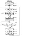
- FIG. 13 shows a flowchart of this process.
- the flowchart shown in FIG. 12 shows the processing of the heater control device 28 and the contact detection control device 29.
- the processing of the heater control device 28 and the contact detection control device 29 will be described as the processing of the control devices 28 and 29.
- the control devices 28 and 29 carry out the processing shown in FIG.
- control devices 28 and 29 start contact detection in S100. Specifically, a predetermined voltage is applied between the transmitting electrode 251 and the receiving electrode 252. As a result, an electric field is formed between the transmitting electrode 251 and the receiving electrode 252.
- control devices 28 and 29 start driving the heater in S102. Specifically, energization of the heat generating portion 22 is started. As a result, the temperature of the heat generating portion 22 rises. Then, the heat generating portion 22 generates heat at a predetermined radiation temperature, and thereby radiates radiant heat that makes the occupant 12 feel warm.
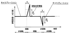
- the control devices 28 and 29 correct the AD value indicating the electrostatic capacitance between the transmitting electrode 251 and the receiving electrode 252 to a reference value for a predetermined period.
- the AD value indicating the capacitance is corrected to 0.
- the AD value indicating the electrostatic capacitance is corrected to 0 at every predetermined time interval Ts. That is, the process of setting the AD value indicating the capacitance between the transmitting electrode 251 and the receiving electrode 252 to 0 and storing it in the memory is repeatedly performed.
- the condition is that the magnitude of change in capacitance between the transmitting electrode 251 and the receiving electrode 252 is less than a predetermined reference value Cb that is smaller than the determination threshold ⁇ A.
- the predetermined time interval Ts is a very short time interval as compared with the reference step T corresponding to the predetermined reference time.
- the magnitude of the change in capacitance between the transmitting electrode 251 and the receiving electrode 252 at the predetermined time interval Ts is equal to or greater than the calibration upper limit Cb, there is a possibility that an object is in contact with the object or the object is not in contact.
- the capacitance is not corrected.
- the magnitude of the change in capacitance between the transmission electrode 251 and the reception electrode 252 at the predetermined time interval Ts is less than the calibration lower limit ⁇ Cb, there is a possibility that the object will contact or the object will not contact. No capacitance correction is performed.
- the control devices 28 and 29 determine in S106 whether or not the change in the capacitance between the transmitting electrode 251 and the receiving electrode 252 in the reference step T is an increase of the determination threshold ⁇ A or more.
- the difference between the detected value of the electrostatic capacitance between the transmitting electrode 251 and the receiving electrode 252 and the detected value of the electrostatic capacitance between the transmitting electrode 251 and the receiving electrode 252 before the reference step T is the determination threshold value. It is determined whether the increase is ⁇ A or more.
- the AD value indicating the capacitance between the transmitting electrode 251 and the receiving electrode 252 is corrected to the reference value after the reference step T
- the value between the transmitting electrode 251 and the receiving electrode 252 corresponding to the correction value is corrected. It is determined whether or not the amount of change in capacitance is an increase of a determination threshold ⁇ A or more.
- the reference step T corresponds to a predetermined unit time.
- the determination threshold ⁇ A is a positive value.
- the control device 28 , 29 returns to the step of S104 without determining that the object has touched.
- the control devices 28 and 29 are , S108, it is determined that the object has come into contact. Then, in S110, the heater output is reduced. Specifically, the energization amount of the heat generating portion 22 is reduced.
- control devices 28 and 29 determine in S112 whether or not the change in the capacitance between the transmission electrode 251 and the reception electrode 252 in the reference step T is a decrease of the determination threshold ⁇ A or more. Specifically, the difference between the detected value of the electrostatic capacitance between the transmitting electrode 251 and the receiving electrode 252 and the detected value of the electrostatic capacitance between the transmitting electrode 251 and the receiving electrode 252 before the reference step T is the determination threshold value. It is determined whether the decrease is ⁇ A or more.
- the control devices 28 and 29 cause the control devices 28 and 29 to S108.
- the heater output is increased. Specifically, the amount of electricity supplied to the heat generating portion 22 is increased so as to reach the amount of electricity before being reduced.
- the control devices 28 and 29 correct the AD value indicating the capacitance between the transmission electrode 251 and the reception electrode 252 to a reference value for a predetermined period that is set in advance.
- the AD value indicating the capacitance is corrected to 0.
- the process of repeatedly setting the AD value indicating the electrostatic capacitance between the transmitting electrode 251 and the receiving electrode 252 to 0 and storing it in the memory is repeatedly performed at predetermined time intervals Ts, and then proceeds to S104.
- the condition is that the magnitude of change in capacitance between the transmitting electrode 251 and the receiving electrode 252 is less than a predetermined reference value Cb that is smaller than the determination threshold ⁇ A.
- the capacitance between the transmitting electrode 251 and the receiving electrode 252 decreases, and when the object separates from the capacitance sensor unit 25, the transmitting electrode 251 In some cases, the capacitance between the receiving electrode 252 and the receiving electrode 252 may increase.
- the contact of the object is determined. Then, when it is determined that the change in the capacitance between the transmission electrode 251 and the reception electrode 252 per predetermined unit time T is a change in the one direction or more that is equal to or more than the second determination threshold value, the non-contact of the object is determined. You can also do it.
- the heater device according to the present embodiment has a structure in which when an object contacts the capacitance sensor unit 25, the temperature of the contacted portion is rapidly lowered, and the temperature of the contacted portion for several seconds to several tens of seconds is thermal. Since the occupant does not feel uncomfortable, the time lag for contact determination does not matter.
- the heater device has the heating portion 22 arranged on the insulating base material 23 and the plurality of electrodes arranged on the insulating base material 23 for detecting contact or non-contact of an object. 251 and 252 are provided. Further, a contact determination unit that determines contact or non-contact of an object based on a change in electrostatic capacitance between the plurality of electrodes 251 and 252 is provided. In addition, the contact determination unit determines the contact of the object when it is determined that the change in capacitance between the plurality of electrodes 251 and 252 per predetermined unit time T is a change in one direction equal to or greater than the determination threshold.
- the change in the capacitance between the plurality of electrodes 251 and 252 per predetermined unit time is a change that is equal to or larger than the determination threshold value in one direction and the opposite direction, it is determined that the object is not in contact.
- the contact determination unit determines that the change in the capacitance between the plurality of electrodes 251 and 252 per predetermined unit time T is a change in one direction equal to or greater than the first determination threshold value. , Determine the contact of objects. Furthermore, when the contact determination unit determines that the change in the capacitance between the plurality of electrodes 251 and 252 per predetermined unit time T is the change in the one direction or the opposite direction of the second determination threshold value or more, Determine non-contact. Therefore, it is possible to more accurately determine contact or non-contact while suppressing the influence of temperature change.
- the heater device of the present embodiment also includes a first correction unit (S104) that corrects the electrostatic capacitance between the plurality of electrodes 251 and 252 to a reference value.
- the first correction unit determines whether the change in capacitance between the plurality of electrodes 251 and 252 per predetermined unit time T is a one-way change that is less than the first determination threshold value, when the contact determination unit determines that the change is one-way.
- the capacitance is corrected to the reference value at every predetermined time interval Ts shorter than the unit time T.
- the condition is that the magnitude of the detected value of the electrostatic capacitance between the plurality of electrodes 251 and 252 is less than a predetermined reference value smaller than the smaller one of the first determination threshold value and the second determination threshold value.
- the contact determination unit determines the change in the capacitance between the plurality of electrodes 251 and 252 per predetermined unit time T from the capacitance between the plurality of electrodes with respect to the reference value corrected by the first correction unit. It is specified as the amount of change.
- the heater device of the present embodiment also includes a second correction unit (S118) that corrects the capacitance between the plurality of electrodes to the reference value.
- the second correction unit determines whether or not the change in capacitance between the plurality of electrodes per predetermined unit time is determined by the contact determination unit to be a change in a direction opposite to the second determination threshold value in the opposite direction.
- the capacitance between the plurality of electrodes is corrected to a reference value at predetermined time intervals (Ts) shorter than the time.
- Ts time intervals
- the contact determination unit specifies the change in the capacitance between the plurality of electrodes per predetermined unit time as the amount of change in the capacitance between the plurality of electrodes with respect to the reference value corrected by the second correction unit. To do.
- the heater device of the present embodiment includes an energization amount lowering unit that lowers the energization amount to the heat generating unit 22 when the contact determination unit determines that the object contacts.
- a heater device according to the second embodiment will be described with reference to FIGS. 15 to 16.
- the heater device of this embodiment has the same configuration as the heater device of the first embodiment.
- the heater device of the present embodiment is different from the heater device of the first embodiment in the processing of the control devices 28 and 29.
- control devices 28 and 29 of this embodiment are different from the control devices 28 and 29 of the first embodiment described above in that the process of step S111 is performed after YES is determined in S106 of FIG. .
- the controller 28, 29 determines YES in S106 and reduces the heater output in S110, in S111, the capacitance between the transmitting electrode 251 and the receiving electrode 252 is reduced for a predetermined period.
- the AD value shown is corrected to the reference value.
- the AD value indicating the electrostatic capacitance is corrected to 0.
- the control devices 28 and 29 repeatedly perform a process of setting the AD value indicating the capacitance between the transmission electrode 251 and the reception electrode 252 to 0 and storing the AD value in the memory at predetermined time intervals Ts.
- the condition is that the magnitude of change in capacitance between the transmitting electrode 251 and the receiving electrode 252 is less than a predetermined reference value Cb that is smaller than the determination threshold ⁇ A.
- the predetermined time interval Ts is a very short time interval as compared with the reference step T corresponding to the predetermined reference time.
- control devices 28 and 29 determine in S112 whether or not the change in the capacitance between the transmission electrode 251 and the reception electrode 252 in the reference step T is a decrease of the determination threshold ⁇ A or more. Specifically, the difference between the detected value of the electrostatic capacitance between the transmitting electrode 251 and the receiving electrode 252 and the detected value of the electrostatic capacitance between the transmitting electrode 251 and the receiving electrode 252 before the reference step T is the determination threshold value. It is determined whether the decrease is ⁇ A or more.
- the process returns to S111. If the change in the capacitance between the transmitting electrode 251 and the receiving electrode 252 in the reference step T is a decrease of the determination threshold ⁇ A or more, the process proceeds to S114.
- the heater control device 28 and the contact detection control device 29 are configured as a computer including a CPU, a memory, an I / O, etc., but the heater control device 28 and the contact detection device are not necessarily such computers. It is not necessary to configure the controller 29.
- the present disclosure is not limited to the above-described embodiment, and can be modified as appropriate. Further, the above embodiments are not unrelated to each other, and can be appropriately combined unless a combination is obviously impossible. Further, in each of the above-described embodiments, it is needless to say that the elements constituting the embodiment are not necessarily essential unless explicitly specified as being essential or in principle considered to be essential. Yes. Further, in each of the above-mentioned embodiments, when numerical values such as the number of components, numerical values, amounts, ranges, etc. of the embodiments are mentioned, it is clearly limited to a particular number and in principle limited to a specific number. The number is not limited to the specific number, except in the case of being performed.
- the heater device is disposed in the insulating base material and the heat generating portion arranged in the insulating base material, and makes contact or non-contact of an object.
- a plurality of electrodes for detection is provided.
- a contact determination unit that determines contact or non-contact of an object based on a change in electrostatic capacitance between the plurality of electrodes is provided. Then, the contact determination unit determines the contact of the object when it is determined that the change in the capacitance between the plurality of electrodes per predetermined unit time is a change in one direction equal to or more than the first determination threshold.
- the contact determination unit determines non-contact of the object when it determines that the change in the capacitance between the plurality of electrodes per predetermined unit time is a change that is equal to or greater than the second determination threshold value in one direction and the opposite direction. To do.
- the heater device includes the first correction unit that corrects the electrostatic capacitance between the plurality of electrodes to the reference value.
- the first correction unit is shorter than the predetermined unit time when the contact determination unit determines that the change in capacitance between the plurality of electrodes per predetermined unit time is a change in one direction that is less than the first determination threshold.
- the capacitance between the plurality of electrodes is corrected to a reference value at predetermined time intervals.
- the condition is that the magnitude of the detected capacitance value between the plurality of electrodes is less than a predetermined reference value that is smaller than the smaller one of the first determination threshold value and the second determination threshold value.
- the contact determination unit specifies the change in the capacitance between the plurality of electrodes per predetermined unit time as the amount of change in the capacitance between the plurality of electrodes with respect to the reference value corrected by the first correction unit. To do.
- the heater device includes a second correction unit that corrects the electrostatic capacitance between the plurality of electrodes to a reference value.
- the second correction unit determines whether or not the change in capacitance between the plurality of electrodes per predetermined unit time is determined by the contact determination unit to be a change in a direction opposite to the second determination threshold value in the opposite direction.
- the capacitance between the plurality of electrodes is corrected to a reference value at predetermined time intervals shorter than the time.
- the condition is that the magnitude of the detected capacitance value between the plurality of electrodes is less than a predetermined reference value that is smaller than the smaller one of the first determination threshold value and the second determination threshold value.
- the contact determination unit specifies the change in the capacitance between the plurality of electrodes per predetermined unit time as the amount of change in the capacitance between the plurality of electrodes with respect to the reference value corrected by the second correction unit. To do.
- the power supply amount lowering unit that lowers the power supply amount to the heat generating unit 22 is provided.
- S106, S108, S112, and S114 correspond to the contact determination unit
- S104 corresponds to the first correction unit
- S118 corresponds to the second correction unit
- S110 corresponds to the power reduction unit.
Abstract
This heater device is provided with: a heating unit (22) arranged on an insulating substrate (23); a plurality of electrodes (251, 252) arranged on the insulating substrate so as to detect whether there is contact with an object; and contact determination units (S106, S108, S112, S114) that determine whether there is contact with the object on the basis of variations in electrostatic capacity between the plurality of electrodes, wherein the contact determination units determine that there is contact with the object when it is determined that the variations in the electrostatic capacity between the plurality of electrodes per predetermined unit time (T) are in one direction and no less than a first determination threshold value, and determine that there is no contact with the object when it is determined that the variations in the electrostatic capacity between the plurality of electrodes per predetermined unit time are in the reverse direction of the one direction and no less than a second determination threshold value.
Description
本出願は、2018年10月9日に出願された日本特許出願番号2018-191138号に基づくもので、ここにその記載内容が参照により組み入れられる。
This application is based on Japanese Patent Application No. 2018-191138 filed on Oct. 9, 2018, the content of which is incorporated herein by reference.
本開示は、ヒータ装置に関するものである。
The present disclosure relates to a heater device.
従来、特許文献1に記載されたヒータ装置がある。この装置は、物体が本体部に接触すると、接触した部位の温度が迅速に低下する輻射ヒータとして構成されている。この装置は、静電容量変化を検出する検出部によって物体が本体部の所定範囲内にあることが検出された場合、通電部への通電量を通常状態よりも少なくなるように通電部の通電量を制御する。
Conventionally, there is a heater device described in Patent Document 1. This device is configured as a radiant heater in which when an object contacts the main body, the temperature of the contacted part is rapidly lowered. This device is designed to energize the current-carrying unit so that the current-carrying amount to the current-carrying unit becomes smaller than in the normal state when the detection unit that detects the change in capacitance detects that the object is within the predetermined range of the main unit. Control the amount.
ところで、上記特許文献1に記載された装置は、静電容量変化を検知することで物体の本体部への接触または近接を判定している。しかしながら、発明者の検討によれば、発熱によって本体部の温度が上昇すると、静電容量が変化して接触または近接を誤判定してしまう可能性がある。このような、温度変化による誤判定を抑制する技術を採用した装置として、特許第5519487号公報に記載されたものがある。この装置は、温度を検知するサーミスタを備え、サーミスタで検知された温度に基づいて静電容量の温度変化に起因する変化量を求め、静電容量の検出値から変化量を除外し、除外された検出値に基づいて手指の接触の有無を判定する。
By the way, the device described in Patent Document 1 determines the contact or proximity of an object to the main body by detecting a change in capacitance. However, according to the study by the inventor, when the temperature of the main body portion rises due to heat generation, there is a possibility that the capacitance changes and the contact or the proximity is erroneously determined. As an apparatus adopting such a technique for suppressing erroneous determination due to temperature change, there is one described in Japanese Patent No. 5519487. This device is equipped with a thermistor that detects the temperature, calculates the amount of change due to the temperature change of the capacitance based on the temperature detected by the thermistor, excludes the amount of change from the detected value of the capacitance, and excludes it. The presence or absence of finger contact is determined based on the detected value.
より具体的には、この装置は、各温度と、当該温度に対応する補正基準値とを対応付けした対応テーブルを予めマイコンの記憶部に記憶している。そして、マイコンは、この対応テーブルを参照して、温度検出値に応じた補正基準値を求め、この補正基準値と静電容量検出値との差分値と閾値との大小関係に基づいて手指の接触の有無を判定する。
More specifically, this device stores a correspondence table in which each temperature is associated with a correction reference value corresponding to the temperature in a storage unit of the microcomputer in advance. Then, the microcomputer refers to this correspondence table to obtain a correction reference value according to the temperature detection value, and based on the magnitude relationship between the difference value between the correction reference value and the capacitance detection value and the threshold value, the finger The presence or absence of contact is determined.
しかしながら、静電容量の温度変化に起因する変化量は、製品毎の個別バラツキが大きい。したがって、上記したような対応テーブルを参照して温度検出値に応じた補正基準値を求め、この補正基準値を用いて手指の接触の有無を判定する構成では、静電容量の温度変化に起因する変化量の個別バラツキを考慮する必要がある。このため、手指の接触判定の感度が低下してしまう。
However, the amount of change in capacitance caused by temperature changes varies greatly from product to product. Therefore, in the configuration in which the correction reference value corresponding to the detected temperature value is obtained by referring to the correspondence table as described above and the presence / absence of finger contact is determined using this correction reference value, It is necessary to consider the individual variation in the amount of change that occurs. For this reason, the sensitivity of the finger contact determination is reduced.
本開示は、温度変化による影響を抑制しつつ、より精度よく接触または非接触を判定できるようにすることを目的とする。
The present disclosure aims to enable more accurate determination of contact or non-contact while suppressing the influence of temperature change.
本開示の1つの観点によれば、ヒータ装置は、絶縁基材に配置された発熱部と、絶縁基材に配置され、物体の接触または非接触を検出するための複数の電極と、複数の電極の間の静電容量の変化に基づいて物体の接触または非接触を判定する接触判定部、を備えている。また、接触判定部は、所定単位時間当たりの複数の電極の間の静電容量の変化が第1判定閾値以上の一方向の変化であると判定した場合、物体の接触を判定し、所定単位時間当たりの複数の電極の間の静電容量の変化が第2判定閾値以上の一方向と逆方向の変化であると判定した場合、物体の非接触を判定する。
According to one aspect of the present disclosure, a heater device includes a heat generating portion arranged on an insulating base material, a plurality of electrodes arranged on the insulating base material, for detecting contact or non-contact of an object, and a plurality of electrodes. A contact determination unit that determines contact or non-contact of an object based on a change in capacitance between the electrodes. In addition, when the contact determination unit determines that the change in the capacitance between the plurality of electrodes per predetermined unit time is a change in one direction that is equal to or larger than the first determination threshold value, the contact determination unit determines the contact of the object and sets the predetermined unit. When it is determined that the change in the capacitance between the plurality of electrodes per time is the change in the one direction or more and the opposite direction that is equal to or more than the second determination threshold value, the non-contact of the object is determined.
このような構成によれば、接触判定部は、所定単位時間当たりの複数の電極の間の静電容量の変化が第1判定閾値以上の一方向の変化であると判定した場合、物体の接触を判定する。さらに、接触判定部は、所定単位時間当たりの複数の電極の間の静電容量の変化が第2判定閾値以上の一方向と逆方向の変化であると判定した場合、物体の非接触を判定する。したがって、温度変化による影響を抑制しつつ、より精度よく接触または非接触を判定することができる。
With such a configuration, when the contact determination unit determines that the change in the capacitance between the plurality of electrodes per predetermined unit time is a change in one direction that is equal to or more than the first determination threshold value, the contact of the object To judge. Further, the contact determination unit determines non-contact of the object when it determines that the change in the capacitance between the plurality of electrodes per predetermined unit time is a change that is equal to or greater than the second determination threshold value in one direction and the opposite direction. To do. Therefore, it is possible to more accurately determine contact or non-contact while suppressing the influence of temperature change.
なお、各構成要素等に付された括弧付きの参照符号は、その構成要素等と後述する実施形態に記載の具体的な構成要素等との対応関係の一例を示すものである。
Note that the reference numerals in parentheses attached to the respective components and the like indicate an example of the correspondence relationship between the components and the like and specific components and the like described in the embodiments described later.
以下、本開示の実施形態について図に基づいて説明する。なお、以下の各実施形態相互において、互いに同一もしくは均等である部分には、図中、同一符号を付してある。
Hereinafter, embodiments of the present disclosure will be described with reference to the drawings. In the following respective embodiments, the same or equivalent parts are designated by the same reference numerals in the drawings.
(第1実施形態)
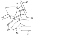
第1実施形態に係るヒータ装置について、図1~図8を用いて説明する。図1に示すように、ヒータ装置20は、道路走行車両などの移動体の室内に設置されている。ヒータ装置20は、室内のための暖房装置の一部を構成している。ヒータ装置20は、移動体に搭載された電池、発電機などの電源から給電されて発熱する電気的なヒータである。ヒータ装置20は、薄い板状に形成されている。ヒータ装置20は、電力が供給されると発熱する。ヒータ装置20は、その表面と垂直な方向に位置付けられた対象物を暖めるために、主としてその表面と垂直な方向へ向けて輻射熱を放射する。 (1st Embodiment)
The heater device according to the first embodiment will be described with reference to FIGS. 1 to 8. As shown in FIG. 1, theheater device 20 is installed in the room of a moving body such as a road vehicle. The heater device 20 constitutes a part of a heating device for the room. The heater device 20 is an electric heater that is powered by a power source such as a battery or a generator mounted on a moving body to generate heat. The heater device 20 is formed in a thin plate shape. The heater device 20 generates heat when electric power is supplied. The heater device 20 radiates radiant heat mainly in a direction perpendicular to the surface of the object in order to warm an object positioned in a direction perpendicular to the surface thereof.
第1実施形態に係るヒータ装置について、図1~図8を用いて説明する。図1に示すように、ヒータ装置20は、道路走行車両などの移動体の室内に設置されている。ヒータ装置20は、室内のための暖房装置の一部を構成している。ヒータ装置20は、移動体に搭載された電池、発電機などの電源から給電されて発熱する電気的なヒータである。ヒータ装置20は、薄い板状に形成されている。ヒータ装置20は、電力が供給されると発熱する。ヒータ装置20は、その表面と垂直な方向に位置付けられた対象物を暖めるために、主としてその表面と垂直な方向へ向けて輻射熱を放射する。 (1st Embodiment)
The heater device according to the first embodiment will be described with reference to FIGS. 1 to 8. As shown in FIG. 1, the
室内には、乗員12が着座するための座席11が設置されている。ヒータ装置20は、乗員12の足元に輻射熱を放射するように室内に設置されている。ヒータ装置20は、たとえば他の暖房装置の起動直後において、乗員12に対して即効的に暖かさを提供するための装置として利用することができる。ヒータ装置20は、室内の壁面に設置される。ヒータ装置20は、想定される通常の姿勢の乗員12に対向するように設置される。道路走行車両は、ハンドル13を支持するためのステアリングコラム14を有している。ヒータ装置20は、ステアリングコラム14の下面と、コラムカバー15の下面に、それぞれ乗員12に対向するように設置されている。
∙ A seat 11 for the passenger 12 to sit in is installed in the room. The heater device 20 is installed indoors so as to radiate radiant heat to the feet of the occupant 12. The heater device 20 can be used as a device for immediately providing warmth to the occupant 12 immediately after the activation of another heating device, for example. The heater device 20 is installed on the wall surface in the room. The heater device 20 is installed so as to face the occupant 12 in an assumed normal posture. The road vehicle has a steering column 14 for supporting the steering wheel 13. The heater device 20 is installed on the lower surface of the steering column 14 and the lower surface of the column cover 15 so as to face the occupant 12, respectively.
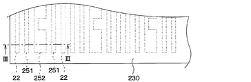
次に、図2~図4を用いて、ヒータ装置20の構成について説明する。図2~図4に示すように、ヒータ装置20は、発熱部22、絶縁基材23、静電容量センサ部25、絶縁層230、ヒータ制御装置28および接触検知制御装置29を有している。ヒータ装置20は、上記特許文献1に記載されたヒータ装置と同様に、物体が静電容量センサ部25に接触すると、接触した部位の温度が迅速に低下する構造を有する輻射ヒータとして構成されている。
Next, the configuration of the heater device 20 will be described with reference to FIGS. 2 to 4. As shown in FIGS. 2 to 4, the heater device 20 includes a heat generating portion 22, an insulating base material 23, a capacitance sensor portion 25, an insulating layer 230, a heater control device 28, and a contact detection control device 29. . Like the heater device described in Patent Document 1, the heater device 20 is configured as a radiant heater having a structure in which when an object comes into contact with the capacitance sensor unit 25, the temperature of the contacted portion is rapidly lowered. There is.
発熱部22、発信電極251および受信電極252は、絶縁基材23における乗員側の面にパターン印刷によって形成されている。本実施形態の発熱部22、発信電極251および受信電極252は、絶縁基材23の一面に配置されている。
The heat generating portion 22, the transmitting electrode 251, and the receiving electrode 252 are formed by pattern printing on the surface of the insulating base material 23 on the occupant side. The heat generating portion 22, the transmitting electrode 251, and the receiving electrode 252 of the present embodiment are arranged on one surface of the insulating base material 23.
絶縁基材23は、ほぼ四角形の薄い板状に形成された絶縁性の樹脂によって構成されている。
The insulating base material 23 is made of an insulating resin formed in a substantially rectangular thin plate shape.
発熱部22は、通電によって発熱する。発熱部22は、発熱することによって、乗員12に暖かさを感じさせる輻射熱を放射することができる。各発熱部22は、高い熱伝導率を有する材料によって作られている。
The heat generating part 22 generates heat when energized. By generating heat, the heat generating part 22 can radiate radiant heat that makes the occupant 12 feel warm. Each heat generating portion 22 is made of a material having high thermal conductivity.
発熱部22は、金属材料によって作ることができる。各発熱部22は、熱伝導率が銅よりも低い材料から選択される。たとえば各発熱部22は、銅、銅とスズとの合金(Cu-Sn)、銀、スズ、ステンレス鋼、ニッケル、ニクロムなどの金属およびこれらを含む合金を用いて構成することができる。
The heat generating part 22 can be made of a metal material. Each heat generating portion 22 is selected from materials having a thermal conductivity lower than that of copper. For example, each heat generating portion 22 can be configured using a metal such as copper, an alloy of copper and tin (Cu—Sn), silver, tin, stainless steel, nickel, or nichrome, and an alloy containing these.
静電容量センサ部25は、発信電極251および受信電極252を有している。発信電極251および受信電極252は、電気抵抗値の比較的小さな金属材料によって作ることができる。発信電極251と受信電極252には、それぞれ接触検知制御装置29が接続されている。
The capacitance sensor unit 25 has a transmission electrode 251 and a reception electrode 252. The transmitting electrode 251 and the receiving electrode 252 can be made of a metal material having a relatively small electric resistance value. A contact detection control device 29 is connected to each of the transmitting electrode 251 and the receiving electrode 252.
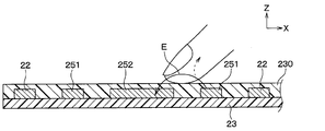
接触検知制御装置29によって、発信電極251と受信電極252の間に所定電圧が印加されると、発信電極251と受信電極252との間に電界が形成される。図3の矢印Eは、電気力線を表している。そして、発信電極251と受信電極252との間に指が近付くと、電気力線Eの一部が指側に移動し、受信電極252で受信される電界が減少する。
When a predetermined voltage is applied between the transmission electrode 251 and the reception electrode 252 by the contact detection control device 29, an electric field is formed between the transmission electrode 251 and the reception electrode 252. An arrow E in FIG. 3 represents a line of electric force. Then, when the finger approaches between the transmitting electrode 251 and the receiving electrode 252, a part of the lines of electric force E moves to the finger side, and the electric field received by the receiving electrode 252 decreases.
絶縁層230は、高い絶縁性を有しており、例えば、ポリイミドフィルム、絶縁樹脂等により構成される。
The insulating layer 230 has a high insulating property, and is made of, for example, a polyimide film or an insulating resin.
ヒータ制御装置28および接触検知制御装置29は、CPU、メモリ、I/O等を備えたコンピュータとして構成されており、CPUは、メモリに記憶されたプログラムに従って各種処理を実施する。メモリは、非遷移的実体的記憶媒体である。
The heater control device 28 and the contact detection control device 29 are configured as a computer including a CPU, a memory, an I / O, and the like, and the CPU executes various processes according to a program stored in the memory. Memory is a non-transitional tangible storage medium.
接触検知制御装置29は、発信電極251と受信電極252との間に電界を形成し、発信電極251と受信電極252との間の静電容量の検出値を収集し、収集した静電容量の検出値をアナログ-デジタル変換した後のAD値としてヒータ制御装置28に出力する。
The contact detection control device 29 forms an electric field between the transmission electrode 251 and the reception electrode 252, collects the detected value of the electrostatic capacitance between the transmission electrode 251 and the reception electrode 252, and collects the collected electrostatic capacitance. The detected value is output to the heater controller 28 as an AD value after analog-digital conversion.
ヒータ制御装置28は、発熱部22への通電を行うものである。ヒータ制御装置28は、接触検知制御装置29から出力される発信電極251と受信電極252との間の静電容量の検出値を示すAD値に基づいて物体の接触または非接触を判定する。
The heater control device 28 energizes the heat generating portion 22. The heater control device 28 determines the contact or non-contact of an object based on the AD value that is output from the contact detection control device 29 and that indicates the detection value of the electrostatic capacitance between the transmission electrode 251 and the reception electrode 252.
次に、静電容量センサ部25の周囲の温度が一定の場合の発信電極251と受信電極252の間の静電容量変化について説明する。図5は、静電容量センサ部25に物体としての手指が接触した後、手指が非接触となった場合の発信電極251と受信電極252の間の静電容量の変化を示した図である。なお、図5には、手指が静電容量センサ部25に接触する手前の状態と、手指が静電容量センサ部25から離れた状態も示してある。図5の縦軸は、発信電極251と受信電極252の間の静電容量の検出値をアナログ-デジタル変換した後のAD値として示してある。図5の横軸は、通電時間となっている。
Next, the change in capacitance between the transmission electrode 251 and the reception electrode 252 when the temperature around the capacitance sensor unit 25 is constant will be described. FIG. 5 is a diagram showing a change in electrostatic capacitance between the transmitting electrode 251 and the receiving electrode 252 when a finger as an object comes into contact with the electrostatic capacitance sensor unit 25 and then the finger becomes non-contact. . In addition, FIG. 5 also shows a state before the fingers are in contact with the capacitance sensor unit 25 and a state in which the fingers are separated from the capacitance sensor unit 25. The vertical axis of FIG. 5 is shown as an AD value after analog-digital conversion of the detected value of the electrostatic capacitance between the transmitting electrode 251 and the receiving electrode 252. The horizontal axis of FIG. 5 represents the energization time.
静電容量センサ部25に手指が接触すると、発信電極251と受信電極252の間の静電容量のAD値は大きくなる。従来のヒータ装置では、発信電極251と受信電極252の間の静電容量のAD値が接触判定閾値よりも大きい場合、物体の接触と判定する。
When a finger touches the capacitance sensor unit 25, the AD value of the capacitance between the transmission electrode 251 and the reception electrode 252 increases. In the conventional heater device, when the AD value of the electrostatic capacitance between the transmitting electrode 251 and the receiving electrode 252 is larger than the contact determination threshold value, it is determined that the object is in contact.
また、静電容量センサ部25から手指が離れると、発信電極251と受信電極252の間の静電容量のAD値は小さくなる。従来のヒータ装置では、発信電極251と受信電極252の間の静電容量のAD値が接触判定閾値以下になった場合、物体の非接触と判定する。
Further, when the fingers are separated from the capacitance sensor unit 25, the AD value of the capacitance between the transmission electrode 251 and the reception electrode 252 becomes smaller. In the conventional heater device, when the AD value of the electrostatic capacitance between the transmitting electrode 251 and the receiving electrode 252 becomes equal to or less than the contact determination threshold value, it is determined that the object is not in contact.
ところで、発熱部22の発熱によって静電容量センサ部25の温度が急速に上昇すると、発信電極251と受信電極252の抵抗値変化や線膨張による寸法変化により発信電極251と受信電極252の間の静電容量が変化する。図6は、同一ロット、同一形状のヒータA~Cにおける通電時間に対する発熱部22の温度と、静電容量の変化を示した図である。
By the way, when the temperature of the capacitance sensor unit 25 rapidly rises due to the heat generation of the heat generating unit 22, a change in resistance between the transmitting electrode 251 and the receiving electrode 252 or a dimensional change due to linear expansion causes a gap between the transmitting electrode 251 and the receiving electrode 252. The capacitance changes. FIG. 6 is a diagram showing changes in the temperature and the capacitance of the heat generating portion 22 with respect to the energization time in the heaters A to C having the same lot and the same shape.
図6に示すように、各ヒータA~Cの温度上昇に伴って各ヒータA~Cの静電容量は低下している。また、同一ロット、同一形状でも、静電容量の変化量に違いがあることが示されている。このように、静電容量の温度変化に起因する変化量は、製品毎の個別バラツキが大きくなっていることが分かる。
As shown in FIG. 6, as the temperature of each heater A to C rises, the electrostatic capacity of each heater A to C decreases. It is also shown that there is a difference in the amount of change in capacitance even in the same lot and the same shape. As described above, it can be seen that the variation amount of the capacitance due to the temperature change has a large individual variation for each product.
したがって、静電容量センサ部25の温度が上昇し、発信電極251と受信電極252の間の静電容量を示すAD値が小さくなると、図7に示すように、静電容量センサ部25に手指が接触しても、静電容量を示すAD値が接触判定閾値に到達しない。したがって、従来のヒータ装置では、静電容量センサ部25に手指が接触したことを判定できないといった問題がある。
Therefore, when the temperature of the capacitance sensor unit 25 rises and the AD value indicating the capacitance between the transmission electrode 251 and the reception electrode 252 decreases, as shown in FIG. Even if is touched, the AD value indicating the capacitance does not reach the contact determination threshold value. Therefore, the conventional heater device has a problem that it cannot determine that the finger touches the capacitance sensor unit 25.
図8は、特許文献1に記載された装置のように、サーミスタで検知された温度に基づいて静電容量の温度変化に起因する変化量を求め、静電容量の検出値から変化量を除外し、除外された検出値に基づいて手指の接触の有無を判定する例を示したものである。
FIG. 8 shows the amount of change caused by a temperature change of the capacitance based on the temperature detected by the thermistor, and excludes the amount of change from the detected value of the capacitance, as in the device described in Patent Document 1. Then, an example is shown in which the presence / absence of a finger contact is determined based on the excluded detection value.
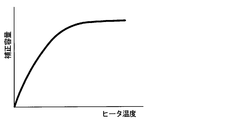
この装置は、図9に示すようなヒータ温度と、当該ヒータ温度に対応する補正容量とを対応付けした対応テーブルを参照して温度検出値に応じた補正容量を求め、この補正容量と静電容量検出値との差分値と閾値との大小関係に基づいて手指の接触の有無を判定する。対応テーブルの特性に近いヒータは、対応テーブルを参照して温度検出値に応じた補正容量を求め、手指の接触の有無を判定することができる。
This apparatus obtains a correction capacity corresponding to a detected temperature value by referring to a correspondence table in which a heater temperature and a correction capacity corresponding to the heater temperature are associated with each other as shown in FIG. The presence / absence of finger contact is determined based on the magnitude relationship between the difference value with the capacitance detection value and the threshold value. The heater having a characteristic close to the characteristics of the correspondence table can determine the correction capacity corresponding to the detected temperature value by referring to the correspondence table, and determine the presence / absence of contact with a finger.
しかしながら、個別バラツキにより対応テーブルの特性から開離した特性のヒータの場合、例えば、図10に示すように、補正容量が大きくなりすぎてしまい、手指が接触していないにもかかわらず、手指が接触したと判定してしまうといった問題がある。また、手指が接触した後、手指が非接触となっても、手指の非接触を判定することができないといった問題もある。
However, in the case of a heater having a characteristic that is separated from the characteristic of the correspondence table due to individual variation, for example, as shown in FIG. 10, the correction capacity becomes too large, and the finger is not touching even though the finger is not in contact. There is a problem that it is determined that they have contacted. Further, there is also a problem that even if the fingers are not in contact with each other after the fingers are in contact with each other, it is impossible to determine the non-contact of the fingers.
また、手指の接触を検出した際にヒータ出力を低減するよう構成されたヒータ装置では、ヒータ出力を低減すると、ヒータ温度が低下し、図11に示すように補正容量は徐々に上昇する。このため、その後、手指が非接触となっても補正容量を示すAD値が接触判定閾値を下回らず、手指が非接触となっているにもかかわらず、非接触と誤判定されるといった問題もある。
Further, in the heater device configured to reduce the heater output when detecting the contact of a finger, when the heater output is reduced, the heater temperature decreases and the correction capacity gradually increases as shown in FIG. Therefore, even if the fingers are not in contact with each other thereafter, the AD value indicating the correction capacity does not fall below the contact determination threshold value, and there is a problem that the contact is erroneously determined as non-contact although the fingers are not in contact. is there.
そこで、本実施形態のヒータ装置は、図12に示すように、所定単位時間T当たりの発信電極251と受信電極252の間の静電容量の変化が判定閾値ΔA以上の増加であると判定した場合、物体の接触を判定する処理を実施する。さらに、本実施形態のヒータ装置は、所定単位時間T当たりの発信電極251と受信電極252の間の静電容量の変化が判定閾値ΔA以上の減少であると判定した場合、物体の非接触を判定する処理を実施する。
Therefore, as shown in FIG. 12, the heater device of the present embodiment determines that the change in the capacitance between the transmitting electrode 251 and the receiving electrode 252 per predetermined unit time T is an increase of the determination threshold ΔA or more. In this case, the process of determining the contact of the object is performed. Further, when the heater device of the present embodiment determines that the change in the capacitance between the transmission electrode 251 and the reception electrode 252 per predetermined unit time T is a decrease of the determination threshold ΔA or more, the heater device does not contact the object. Perform the determination process.
図13に、この処理のフローチャートを示す。なお、図12に示すフローチャートは、ヒータ制御装置28および接触検知制御装置29の処理を示している。ここでは、ヒータ制御装置28および接触検知制御装置29の処理を制御装置28、29の処理として説明する。制御装置28、29は、ヒータ装置20が動作状態になると、図13に示す処理を実施する。
Fig. 13 shows a flowchart of this process. The flowchart shown in FIG. 12 shows the processing of the heater control device 28 and the contact detection control device 29. Here, the processing of the heater control device 28 and the contact detection control device 29 will be described as the processing of the control devices 28 and 29. When the heater device 20 is in the operating state, the control devices 28 and 29 carry out the processing shown in FIG.
まず、制御装置28、29は、S100にて、接触検知をスタートする。具体的には、発信電極251と受信電極252の間に所定電圧を印加する。これにより、発信電極251と受信電極252との間に電界が形成される。
First, the control devices 28 and 29 start contact detection in S100. Specifically, a predetermined voltage is applied between the transmitting electrode 251 and the receiving electrode 252. As a result, an electric field is formed between the transmitting electrode 251 and the receiving electrode 252.
次に、制御装置28、29は、S102にて、ヒータ駆動をスタートする。具体的には、発熱部22への通電を開始する。これにより、発熱部22の温度は上昇する。そして、発熱部22が所定放射温度に発熱することによって、乗員12に暖かさを感じさせる輻射熱を放射する。
Next, the control devices 28 and 29 start driving the heater in S102. Specifically, energization of the heat generating portion 22 is started. As a result, the temperature of the heat generating portion 22 rises. Then, the heat generating portion 22 generates heat at a predetermined radiation temperature, and thereby radiates radiant heat that makes the occupant 12 feel warm.
次に、制御装置28、29は、S104にて、予め定められた所定期間、発信電極251と受信電極252の間の静電容量を示すAD値を基準値に補正する。本実施形態では、静電容量を示すAD値を0に補正する。具体的には、図14に示すように、所定時間間隔Ts毎に、静電容量を示すAD値を0に補正する。すなわち、発信電極251と受信電極252の間の静電容量示すAD値を0としてメモリに記憶させる処理を繰り返し実施する。ただし、発信電極251と受信電極252の間の静電容量の変化の大きさが判定閾値ΔAよりも小さな所定基準値Cb未満であることを条件とする。ここで、所定時間間隔Tsは、所定基準時間に相当する基準ステップTと比較して非常に短い時間間隔となっている。
Next, in S104, the control devices 28 and 29 correct the AD value indicating the electrostatic capacitance between the transmitting electrode 251 and the receiving electrode 252 to a reference value for a predetermined period. In the present embodiment, the AD value indicating the capacitance is corrected to 0. Specifically, as shown in FIG. 14, the AD value indicating the electrostatic capacitance is corrected to 0 at every predetermined time interval Ts. That is, the process of setting the AD value indicating the capacitance between the transmitting electrode 251 and the receiving electrode 252 to 0 and storing it in the memory is repeatedly performed. However, the condition is that the magnitude of change in capacitance between the transmitting electrode 251 and the receiving electrode 252 is less than a predetermined reference value Cb that is smaller than the determination threshold ΔA. Here, the predetermined time interval Ts is a very short time interval as compared with the reference step T corresponding to the predetermined reference time.
なお、所定時間間隔Tsにおける発信電極251と受信電極252の間の静電容量の変化の大きさがキャリブレーション上限Cb以上の場合は、物体の接触または物体の非接触の可能性があるため静電容量の補正は実施しない。また、所定時間間隔Tsにおける発信電極251と受信電極252の間の静電容量の変化の大きさがキャリブレーション下限―Cb未満の場合も、物体の接触または物体の非接触の可能性があるため静電容量の補正は実施しない。
If the magnitude of the change in capacitance between the transmitting electrode 251 and the receiving electrode 252 at the predetermined time interval Ts is equal to or greater than the calibration upper limit Cb, there is a possibility that an object is in contact with the object or the object is not in contact. The capacitance is not corrected. Further, even when the magnitude of the change in capacitance between the transmission electrode 251 and the reception electrode 252 at the predetermined time interval Ts is less than the calibration lower limit −Cb, there is a possibility that the object will contact or the object will not contact. No capacitance correction is performed.
次に、制御装置28、29は、S106にて、基準ステップTにおける発信電極251と受信電極252の間の静電容量の変化が、判定閾値ΔA以上の増加であるか否かを判定する。具体的には、発信電極251と受信電極252の間の静電容量の検出値と、基準ステップT前の発信電極251と受信電極252の間の静電容量の検出値との差分が判定閾値ΔA以上の増加であるか否かを判定する。なお、基準ステップT前より後に発信電極251と受信電極252の間の静電容量を示すAD値が基準値に補正されている場合には、補正値に対する発信電極251と受信電極252の間の静電容量の変化量が判定閾値ΔA以上の増加であるか否かを判定する。ここで、基準ステップTは、所定単位時間に相当する。また、判定閾値ΔAは正の値となっている。
Next, the control devices 28 and 29 determine in S106 whether or not the change in the capacitance between the transmitting electrode 251 and the receiving electrode 252 in the reference step T is an increase of the determination threshold ΔA or more. Specifically, the difference between the detected value of the electrostatic capacitance between the transmitting electrode 251 and the receiving electrode 252 and the detected value of the electrostatic capacitance between the transmitting electrode 251 and the receiving electrode 252 before the reference step T is the determination threshold value. It is determined whether the increase is ΔA or more. In addition, when the AD value indicating the capacitance between the transmitting electrode 251 and the receiving electrode 252 is corrected to the reference value after the reference step T, the value between the transmitting electrode 251 and the receiving electrode 252 corresponding to the correction value is corrected. It is determined whether or not the amount of change in capacitance is an increase of a determination threshold ΔA or more. Here, the reference step T corresponds to a predetermined unit time. Further, the determination threshold ΔA is a positive value.
ここで、物体が静電容量センサ部25に接触しておらず、基準ステップTの期間に発信電極251と受信電極252の間の静電容量が判定閾値ΔA以上の増加でない場合、制御装置28、29は、物体が接触したと判定することなく、S104のステップに戻る。
Here, if the object is not in contact with the capacitance sensor unit 25 and the capacitance between the transmission electrode 251 and the reception electrode 252 does not increase by the determination threshold ΔA or more during the reference step T, the control device 28 , 29 returns to the step of S104 without determining that the object has touched.
また、物体が静電容量センサ部25に接触し、基準ステップTにおける発信電極251と受信電極252の間の静電容量の変化が判定閾値ΔA以上の増加である場合、制御装置28、29は、S108にて、物体が接触したと判定する。そして、S110にて、ヒータ出力を低減する。具体的には、発熱部22の通電量を低下させる。
When the object contacts the capacitance sensor unit 25 and the change in the capacitance between the transmission electrode 251 and the reception electrode 252 in the reference step T is an increase of the determination threshold ΔA or more, the control devices 28 and 29 are , S108, it is determined that the object has come into contact. Then, in S110, the heater output is reduced. Specifically, the energization amount of the heat generating portion 22 is reduced.
次に、制御装置28、29は、S112にて、基準ステップTにおける発信電極251と受信電極252の間の静電容量の変化が、判定閾値ΔA以上の低下であるか否かを判定する。具体的には、発信電極251と受信電極252の間の静電容量の検出値と、基準ステップT前の発信電極251と受信電極252の間の静電容量の検出値との差分が判定閾値ΔA以上の低下であるか否かを判定する。
Next, the control devices 28 and 29 determine in S112 whether or not the change in the capacitance between the transmission electrode 251 and the reception electrode 252 in the reference step T is a decrease of the determination threshold ΔA or more. Specifically, the difference between the detected value of the electrostatic capacitance between the transmitting electrode 251 and the receiving electrode 252 and the detected value of the electrostatic capacitance between the transmitting electrode 251 and the receiving electrode 252 before the reference step T is the determination threshold value. It is determined whether the decrease is ΔA or more.
ここで、物体が静電容量センサ部25から離れ、基準ステップTにおける発信電極251と受信電極252の間の静電容量が判定閾値ΔA以上の低下である場合、制御装置28、29は、S108にて、物体が非接触となったと判定する。そして、S116にて、ヒータ出力を増大させる。具体的には、発熱部22の通電量を低下させる前の通電量となるよう増加させる。
Here, when the object is separated from the capacitance sensor unit 25 and the capacitance between the transmission electrode 251 and the reception electrode 252 in the reference step T is a decrease of the determination threshold ΔA or more, the control devices 28 and 29 cause the control devices 28 and 29 to S108. At, it is determined that the object has become non-contact. Then, in S116, the heater output is increased. Specifically, the amount of electricity supplied to the heat generating portion 22 is increased so as to reach the amount of electricity before being reduced.
次に、制御装置28、29は、S118にて、予め定められた所定期間、発信電極251と受信電極252の間の静電容量を示すAD値を基準値に補正する。本実施形態では、静電容量を示すAD値を0に補正する。具体的には、図14に示すように、所定時間間隔Ts毎に、発信電極251と受信電極252の間の静電容量示すAD値を0としてメモリに記憶させる処理を繰り返し実施し、S104へ戻る。ただし、発信電極251と受信電極252の間の静電容量の変化の大きさが判定閾値ΔAよりも小さな所定基準値Cb未満であることを条件とする。
Next, in S118, the control devices 28 and 29 correct the AD value indicating the capacitance between the transmission electrode 251 and the reception electrode 252 to a reference value for a predetermined period that is set in advance. In the present embodiment, the AD value indicating the capacitance is corrected to 0. Specifically, as shown in FIG. 14, the process of repeatedly setting the AD value indicating the electrostatic capacitance between the transmitting electrode 251 and the receiving electrode 252 to 0 and storing it in the memory is repeatedly performed at predetermined time intervals Ts, and then proceeds to S104. Return. However, the condition is that the magnitude of change in capacitance between the transmitting electrode 251 and the receiving electrode 252 is less than a predetermined reference value Cb that is smaller than the determination threshold ΔA.
ところで、本実施形態では、物体が静電容量センサ部25に接触した際に、発信電極251と受信電極252の間の静電容量が増加し、物体が静電容量センサ部25から離れた際に、発信電極251と受信電極252の間の静電容量が低下する例を示した。
By the way, in the present embodiment, when an object contacts the capacitance sensor unit 25, the capacitance between the transmitting electrode 251 and the receiving electrode 252 increases, and when the object separates from the capacitance sensor unit 25. In the above, an example in which the electrostatic capacitance between the transmitting electrode 251 and the receiving electrode 252 decreases is shown.
しかし、物体が静電容量センサ部25に接触した際に、発信電極251と受信電極252の間の静電容量が低下し、物体が静電容量センサ部25から離れた際に、発信電極251と受信電極252の間の静電容量が増加する場合もある。
However, when an object contacts the capacitance sensor unit 25, the capacitance between the transmitting electrode 251 and the receiving electrode 252 decreases, and when the object separates from the capacitance sensor unit 25, the transmitting electrode 251 In some cases, the capacitance between the receiving electrode 252 and the receiving electrode 252 may increase.
したがって、所定単位時間T当たりの発信電極251と受信電極252の間の静電容量の変化が第1判定閾値以上の一方向の変化であると判定した場合、物体の接触を判定する。そして、所定単位時間T当たりの発信電極251と受信電極252の間の静電容量の変化が第2判定閾値以上の一方向と逆方向の変化であると判定した場合、物体の非接触を判定することもできる。
Therefore, if it is determined that the change in the capacitance between the transmission electrode 251 and the reception electrode 252 per predetermined unit time T is a change in one direction that is equal to or more than the first determination threshold, the contact of the object is determined. Then, when it is determined that the change in the capacitance between the transmission electrode 251 and the reception electrode 252 per predetermined unit time T is a change in the one direction or more that is equal to or more than the second determination threshold value, the non-contact of the object is determined. You can also do it.
本実施形態のヒータ装置では、例えば、基準ステップT=2秒とした場合、物体が静電容量センサ部25に接触してから2秒間程度で物体の接触を判定し、ヒータ出力を低減させる。しかし、本実施形態のヒータ装置は、物体が静電容量センサ部25に接触すると、接触した部位の温度が迅速に低下する構造を有しており、数秒~数十秒の接触においては熱的不快感を乗員に感じさせることがないので接触判定のタイムラグは問題とならない。
In the heater device of the present embodiment, when the reference step T = 2 seconds, for example, the contact of the object is determined within about 2 seconds after the object contacts the capacitance sensor unit 25, and the heater output is reduced. However, the heater device according to the present embodiment has a structure in which when an object contacts the capacitance sensor unit 25, the temperature of the contacted portion is rapidly lowered, and the temperature of the contacted portion for several seconds to several tens of seconds is thermal. Since the occupant does not feel uncomfortable, the time lag for contact determination does not matter.
以上、説明したように、本実施形態のヒータ装置は、絶縁基材23に配置された発熱部22と、絶縁基材23に配置され、物体の接触または非接触を検出するための複数の電極251、252と、を備えている。また、複数の電極251、252の間の静電容量の変化に基づいて物体の接触または非接触を判定する接触判定部を備えている。また、接触判定部は、所定単位時間T当たりの複数の電極251、252の間の静電容量の変化が判定閾値以上の一方向の変化であると判定した場合、物体の接触を判定する。また、所定単位時間当たりの複数の電極251、252の間の静電容量の変化が判定閾値以上の一方向と逆方向の変化であると判定した場合、物体の非接触を判定する。
As described above, the heater device according to the present embodiment has the heating portion 22 arranged on the insulating base material 23 and the plurality of electrodes arranged on the insulating base material 23 for detecting contact or non-contact of an object. 251 and 252 are provided. Further, a contact determination unit that determines contact or non-contact of an object based on a change in electrostatic capacitance between the plurality of electrodes 251 and 252 is provided. In addition, the contact determination unit determines the contact of the object when it is determined that the change in capacitance between the plurality of electrodes 251 and 252 per predetermined unit time T is a change in one direction equal to or greater than the determination threshold. Further, when it is determined that the change in the capacitance between the plurality of electrodes 251 and 252 per predetermined unit time is a change that is equal to or larger than the determination threshold value in one direction and the opposite direction, it is determined that the object is not in contact.
このような構成によれば、接触判定部は、所定単位時間T当たりの複数の電極251、252の間の静電容量の変化が第1判定閾値以上の一方向の変化であると判定した場合、物体の接触を判定する。さらに、接触判定部は、所定単位時間T当たりの複数の電極251、252の間の静電容量の変化が第2判定閾値以上の一方向と逆方向の変化であると判定した場合、物体の非接触を判定する。したがって、温度変化による影響を抑制しつつ、より精度よく接触または非接触を判定することができる。
According to such a configuration, when the contact determination unit determines that the change in the capacitance between the plurality of electrodes 251 and 252 per predetermined unit time T is a change in one direction equal to or greater than the first determination threshold value. , Determine the contact of objects. Furthermore, when the contact determination unit determines that the change in the capacitance between the plurality of electrodes 251 and 252 per predetermined unit time T is the change in the one direction or the opposite direction of the second determination threshold value or more, Determine non-contact. Therefore, it is possible to more accurately determine contact or non-contact while suppressing the influence of temperature change.
また、本実施形態のヒータ装置は、複数の電極251、252の間の静電容量を基準値に補正する第1補正部(S104)を備えている。第1補正部は、接触判定部により所定単位時間T当たりの複数の電極251、252の間の静電容量の変化が第1判定閾値未満の一方向の変化であると判定された場合、所定単位時間Tより短い所定時間間隔Ts毎に、静電容量を基準値に補正する。ただし、複数の電極251、252の間の静電容量の検出値の大きさが第1判定閾値および第2判定閾値の小さい方の値よりも小さな所定基準値未満であることを条件とする。
The heater device of the present embodiment also includes a first correction unit (S104) that corrects the electrostatic capacitance between the plurality of electrodes 251 and 252 to a reference value. The first correction unit determines whether the change in capacitance between the plurality of electrodes 251 and 252 per predetermined unit time T is a one-way change that is less than the first determination threshold value, when the contact determination unit determines that the change is one-way. The capacitance is corrected to the reference value at every predetermined time interval Ts shorter than the unit time T. However, the condition is that the magnitude of the detected value of the electrostatic capacitance between the plurality of electrodes 251 and 252 is less than a predetermined reference value smaller than the smaller one of the first determination threshold value and the second determination threshold value.
そして、接触判定部は、所定単位時間T当たりの複数の電極251、252の間の静電容量の変化を、第1補正部により補正された基準値に対する複数の電極の間の静電容量の変化量として特定する。
Then, the contact determination unit determines the change in the capacitance between the plurality of electrodes 251 and 252 per predetermined unit time T from the capacitance between the plurality of electrodes with respect to the reference value corrected by the first correction unit. It is specified as the amount of change.
したがって、物体の接触判定の直前における所定単位時間T中の温度変化による静電容量の変化の影響を抑制することが可能である。また、温度変化に伴って静電容量の大きさが大きくなりすぎると、静電容量の演算時にオーバーフローする可能性がある。しかし、静電容量を基準値に補正することにより、オーバーフローを生じさないようにすることができ、精度よく物体の接触判定を実施することができる。
Therefore, it is possible to suppress the influence of the change in capacitance due to the temperature change during the predetermined unit time T immediately before the contact judgment of the object. Further, if the magnitude of the capacitance becomes too large as the temperature changes, there is a possibility that the capacitance may overflow when the capacitance is calculated. However, by correcting the electrostatic capacitance to the reference value, it is possible to prevent the overflow from occurring, and it is possible to accurately determine the contact of the object.
また、本実施形態のヒータ装置は、複数の電極の間の静電容量を基準値に補正する第2補正部(S118)を備えている。第2補正部は、接触判定部により所定単位時間当たりの複数の電極の間の静電容量の変化が第2判定閾値以上の一方向と逆方向の変化であると判定された場合、所定単位時間より短い所定時間間隔(Ts)毎に、複数の電極の間の静電容量を基準値に補正する。ただし、複数の電極の間の静電容量の検出値の大きさが第1判定閾値および第2判定閾値の小さい方の値よりも小さな所定基準値未満であることを条件とする。
The heater device of the present embodiment also includes a second correction unit (S118) that corrects the capacitance between the plurality of electrodes to the reference value. The second correction unit determines whether or not the change in capacitance between the plurality of electrodes per predetermined unit time is determined by the contact determination unit to be a change in a direction opposite to the second determination threshold value in the opposite direction. The capacitance between the plurality of electrodes is corrected to a reference value at predetermined time intervals (Ts) shorter than the time. However, the condition is that the magnitude of the detected capacitance value between the plurality of electrodes is less than a predetermined reference value that is smaller than the smaller one of the first determination threshold value and the second determination threshold value.
そして、接触判定部は、所定単位時間当たりの複数の電極の間の静電容量の変化を、第2補正部により補正された基準値に対する複数の電極の間の静電容量の変化量として特定する。
Then, the contact determination unit specifies the change in the capacitance between the plurality of electrodes per predetermined unit time as the amount of change in the capacitance between the plurality of electrodes with respect to the reference value corrected by the second correction unit. To do.
したがって、物体の非接触判定の直後における所定単位時間T中の温度変化による静電容量の変化の影響を抑制することが可能である。また、温度変化に伴って静電容量の大きさが大きくなりすぎると、静電容量の演算時にオーバーフローする可能性がある。しかし、静電容量を基準値に補正することにより、オーバーフローを生じさないようにすることができ、精度よく物体の接触判定を実施することができる。
Therefore, it is possible to suppress the influence of the change in capacitance due to the temperature change during the predetermined unit time T immediately after the non-contact judgment of the object. Further, if the magnitude of the capacitance becomes too large as the temperature changes, there is a possibility that the capacitance may overflow when the capacitance is calculated. However, by correcting the electrostatic capacitance to the reference value, it is possible to prevent the overflow from occurring, and it is possible to accurately determine the contact of the object.
また、本実施形態のヒータ装置は、接触判定部により、物体の接触が判定された場合、発熱部22への通電量を低下させる通電量低下部を備えている。
In addition, the heater device of the present embodiment includes an energization amount lowering unit that lowers the energization amount to the heat generating unit 22 when the contact determination unit determines that the object contacts.
したがって、温度変化による影響を受けることなく、より精度よく物体の接触を判定して、発熱部22への通電量を低下させることができる。
Therefore, it is possible to more accurately determine the contact of the object and reduce the amount of electricity to the heat generating portion 22 without being affected by the temperature change.
(第2実施形態)
第2実施形態に係るヒータ装置について図15~図16を用いて説明する。本実施形態のヒータ装置の構成は、上記第1実施形態のヒータ装置と同じである。本実施形態のヒータ装置は、上記第1実施形態のヒータ装置と比較して、制御装置28、29の処理が異なる。 (2nd Embodiment)
A heater device according to the second embodiment will be described with reference to FIGS. 15 to 16. The heater device of this embodiment has the same configuration as the heater device of the first embodiment. The heater device of the present embodiment is different from the heater device of the first embodiment in the processing of the control devices 28 and 29.
第2実施形態に係るヒータ装置について図15~図16を用いて説明する。本実施形態のヒータ装置の構成は、上記第1実施形態のヒータ装置と同じである。本実施形態のヒータ装置は、上記第1実施形態のヒータ装置と比較して、制御装置28、29の処理が異なる。 (2nd Embodiment)
A heater device according to the second embodiment will be described with reference to FIGS. 15 to 16. The heater device of this embodiment has the same configuration as the heater device of the first embodiment. The heater device of the present embodiment is different from the heater device of the first embodiment in the processing of the
本実施形態の制御装置28、29のフローチャートを図15に示す。本実施形態の制御装置28、29は、上記第1実施形態の制御装置28、29と比較して、図13におけるS106にてYESと判定された後、ステップS111の処理を実施する点が異なる。
A flowchart of the control devices 28 and 29 of this embodiment is shown in FIG. The control devices 28 and 29 of the present embodiment are different from the control devices 28 and 29 of the first embodiment described above in that the process of step S111 is performed after YES is determined in S106 of FIG. .
制御装置28、29は、S106にてYESと判定され、S110にて、ヒータ出力を低減すると、S111にて、予め定められた所定期間、発信電極251と受信電極252の間の静電容量を示すAD値を基準値に補正する。本実施形態では、図16に示すように、接触判定の後、静電容量を示すAD値を0に補正する。具体的には、制御装置28、29は、所定時間間隔Ts毎に、発信電極251と受信電極252の間の静電容量示すAD値を0としてメモリに記憶させる処理を繰り返し実施する。ただし、発信電極251と受信電極252の間の静電容量の変化の大きさが判定閾値ΔAよりも小さな所定基準値Cb未満であることを条件とする。ここで、所定時間間隔Tsは、所定基準時間に相当する基準ステップTと比較して非常に短い時間間隔となっている。
When the controller 28, 29 determines YES in S106 and reduces the heater output in S110, in S111, the capacitance between the transmitting electrode 251 and the receiving electrode 252 is reduced for a predetermined period. The AD value shown is corrected to the reference value. In the present embodiment, as shown in FIG. 16, after the contact determination, the AD value indicating the electrostatic capacitance is corrected to 0. Specifically, the control devices 28 and 29 repeatedly perform a process of setting the AD value indicating the capacitance between the transmission electrode 251 and the reception electrode 252 to 0 and storing the AD value in the memory at predetermined time intervals Ts. However, the condition is that the magnitude of change in capacitance between the transmitting electrode 251 and the receiving electrode 252 is less than a predetermined reference value Cb that is smaller than the determination threshold ΔA. Here, the predetermined time interval Ts is a very short time interval as compared with the reference step T corresponding to the predetermined reference time.
次に、制御装置28、29は、S112にて、基準ステップTにおける発信電極251と受信電極252の間の静電容量の変化が、判定閾値ΔA以上の低下であるか否かを判定する。具体的には、発信電極251と受信電極252の間の静電容量の検出値と、基準ステップT前の発信電極251と受信電極252の間の静電容量の検出値との差分が判定閾値ΔA以上の低下であるか否かを判定する。
Next, the control devices 28 and 29 determine in S112 whether or not the change in the capacitance between the transmission electrode 251 and the reception electrode 252 in the reference step T is a decrease of the determination threshold ΔA or more. Specifically, the difference between the detected value of the electrostatic capacitance between the transmitting electrode 251 and the receiving electrode 252 and the detected value of the electrostatic capacitance between the transmitting electrode 251 and the receiving electrode 252 before the reference step T is the determination threshold value. It is determined whether the decrease is ΔA or more.
ここで、基準ステップTにおける発信電極251と受信電極252の間の静電容量の変化が、判定閾値ΔA未満の場合、S111に戻る。また、基準ステップTにおける発信電極251と受信電極252の間の静電容量の変化が、判定閾値ΔA以上の低下である場合、S114へ進む。
Here, if the change in capacitance between the transmitting electrode 251 and the receiving electrode 252 in the reference step T is less than the determination threshold ΔA, the process returns to S111. If the change in the capacitance between the transmitting electrode 251 and the receiving electrode 252 in the reference step T is a decrease of the determination threshold ΔA or more, the process proceeds to S114.
本実施形態では、上記第1実施形態と共通の構成から奏される同様の効果を上記第1実施形態と同様に得ることができる。
In the present embodiment, the same effect as that obtained from the configuration common to the first embodiment can be obtained similarly to the first embodiment.
(他の実施形態)
(1)上記各実施形態では、CPU、メモリ、I/O等を備えたコンピュータとしてヒータ制御装置28および接触検知制御装置29を構成したが、必ずしもこのようなコンピュータとしてヒータ制御装置28および接触検知制御装置29を構成する必要はない。 (Other embodiments)
(1) In each of the above embodiments, theheater control device 28 and the contact detection control device 29 are configured as a computer including a CPU, a memory, an I / O, etc., but the heater control device 28 and the contact detection device are not necessarily such computers. It is not necessary to configure the controller 29.
(1)上記各実施形態では、CPU、メモリ、I/O等を備えたコンピュータとしてヒータ制御装置28および接触検知制御装置29を構成したが、必ずしもこのようなコンピュータとしてヒータ制御装置28および接触検知制御装置29を構成する必要はない。 (Other embodiments)
(1) In each of the above embodiments, the
(2)上記各実施形態では、物体が静電容量センサ部25に接触し、基準ステップTにおける発信電極251と受信電極252の間の静電容量の変化が判定閾値ΔA以上の増加である場合、制御装置28、29は、S110にて、ヒータ出力を低減するようにした。これに対し、ヒータ出力を停止させてもよい。
(2) In each of the above embodiments, when an object contacts the capacitance sensor unit 25 and the change in capacitance between the transmission electrode 251 and the reception electrode 252 in the reference step T is an increase of the determination threshold ΔA or more. The control devices 28 and 29 are configured to reduce the heater output in S110. On the other hand, the heater output may be stopped.
なお、本開示は上記した実施形態に限定されるものではなく、適宜変更が可能である。また、上記各実施形態は、互いに無関係なものではなく、組み合わせが明らかに不可な場合を除き、適宜組み合わせが可能である。また、上記各実施形態において、実施形態を構成する要素は、特に必須であると明示した場合および原理的に明らかに必須であると考えられる場合等を除き、必ずしも必須のものではないことは言うまでもない。また、上記各実施形態において、実施形態の構成要素の個数、数値、量、範囲等の数値が言及されている場合、特に必須であると明示した場合および原理的に明らかに特定の数に限定される場合等を除き、その特定の数に限定されるものではない。また、上記各実施形態において、構成要素等の材質、形状、位置関係等に言及するときは、特に明示した場合および原理的に特定の材質、形状、位置関係等に限定される場合等を除き、その材質、形状、位置関係等に限定されるものではない。
It should be noted that the present disclosure is not limited to the above-described embodiment, and can be modified as appropriate. Further, the above embodiments are not unrelated to each other, and can be appropriately combined unless a combination is obviously impossible. Further, in each of the above-described embodiments, it is needless to say that the elements constituting the embodiment are not necessarily essential unless explicitly specified as being essential or in principle considered to be essential. Yes. Further, in each of the above-mentioned embodiments, when numerical values such as the number of components, numerical values, amounts, ranges, etc. of the embodiments are mentioned, it is clearly limited to a particular number and in principle limited to a specific number. The number is not limited to the specific number, except in the case of being performed. Further, in each of the above-mentioned embodiments, when referring to the material, shape, positional relationship, etc. of the constituent elements, etc., unless specifically stated or in principle limited to a specific material, shape, positional relationship, etc. However, the material, shape, positional relationship, etc. are not limited.
(まとめ)/*
上記各実施形態の一部または全部で示された第1の観点によれば、ヒータ装置は、絶縁基材に配置された発熱部と、絶縁基材に配置され、物体の接触または非接触を検出するための複数の電極と、を備えている。また、複数の電極の間の静電容量の変化に基づいて物体の接触または非接触を判定する接触判定部を備えている。そして、接触判定部は、所定単位時間当たりの複数の電極の間の静電容量の変化が第1判定閾値以上の一方向の変化であると判定した場合、物体の接触を判定する。さらに、接触判定部は、所定単位時間当たりの複数の電極の間の静電容量の変化が第2判定閾値以上の一方向と逆方向の変化であると判定した場合、物体の非接触を判定する。 (Summary) / *
According to the first aspect shown in part or all of each of the above-described embodiments, the heater device is disposed in the insulating base material and the heat generating portion arranged in the insulating base material, and makes contact or non-contact of an object. A plurality of electrodes for detection. In addition, a contact determination unit that determines contact or non-contact of an object based on a change in electrostatic capacitance between the plurality of electrodes is provided. Then, the contact determination unit determines the contact of the object when it is determined that the change in the capacitance between the plurality of electrodes per predetermined unit time is a change in one direction equal to or more than the first determination threshold. Further, the contact determination unit determines non-contact of the object when it determines that the change in the capacitance between the plurality of electrodes per predetermined unit time is a change that is equal to or greater than the second determination threshold value in one direction and the opposite direction. To do.
また、第2の観点によれば、ヒータ装置は、複数の電極の間の静電容量を基準値に補正する第1補正部を備えている。第1補正部は、接触判定部により所定単位時間当たりの複数の電極の間の静電容量の変化が第1判定閾値未満の一方向の変化であると判定された場合、所定単位時間より短い所定時間間隔毎に、複数の電極の間の静電容量を基準値に補正する。ただし、複数の電極の間の静電容量の検出値の大きさが第1判定閾値および第2判定閾値の小さい方の値よりも小さな所定基準値未満であることを条件とする。
Further, according to the second aspect, the heater device includes the first correction unit that corrects the electrostatic capacitance between the plurality of electrodes to the reference value. The first correction unit is shorter than the predetermined unit time when the contact determination unit determines that the change in capacitance between the plurality of electrodes per predetermined unit time is a change in one direction that is less than the first determination threshold. The capacitance between the plurality of electrodes is corrected to a reference value at predetermined time intervals. However, the condition is that the magnitude of the detected capacitance value between the plurality of electrodes is less than a predetermined reference value that is smaller than the smaller one of the first determination threshold value and the second determination threshold value.
そして、接触判定部は、所定単位時間当たりの複数の電極の間の静電容量の変化を、第1補正部により補正された基準値に対する複数の電極の間の静電容量の変化量として特定する。
Then, the contact determination unit specifies the change in the capacitance between the plurality of electrodes per predetermined unit time as the amount of change in the capacitance between the plurality of electrodes with respect to the reference value corrected by the first correction unit. To do.
したがって、物体の接触判定の直前における所定単位時間T中の温度変化による静電容量の変化の影響を抑制することが可能である。また、温度変化に伴って静電容量の大きさが大きくなりすぎると、静電容量の演算時にオーバーフローする可能性がある。しかし、静電容量を基準値に補正することにより、オーバーフローを生じさないようにすることができ、精度よく物体の接触判定を実施することができる。
Therefore, it is possible to suppress the influence of the change in capacitance due to the temperature change during the predetermined unit time T immediately before the contact judgment of the object. Further, if the magnitude of the capacitance becomes too large as the temperature changes, there is a possibility that the capacitance may overflow when the capacitance is calculated. However, by correcting the electrostatic capacitance to the reference value, it is possible to prevent the overflow from occurring, and it is possible to accurately determine the contact of the object.
また、第3の観点によれば、ヒータ装置は、複数の電極の間の静電容量を基準値に補正する第2補正部を備えている。第2補正部は、接触判定部により所定単位時間当たりの複数の電極の間の静電容量の変化が第2判定閾値以上の一方向と逆方向の変化であると判定された場合、所定単位時間より短い所定時間間隔毎に、複数の電極の間の静電容量を基準値に補正する。ただし、複数の電極の間の静電容量の検出値の大きさが第1判定閾値および第2判定閾値の小さい方の値よりも小さな所定基準値未満であることを条件とする。
Also, according to the third aspect, the heater device includes a second correction unit that corrects the electrostatic capacitance between the plurality of electrodes to a reference value. The second correction unit determines whether or not the change in capacitance between the plurality of electrodes per predetermined unit time is determined by the contact determination unit to be a change in a direction opposite to the second determination threshold value in the opposite direction. The capacitance between the plurality of electrodes is corrected to a reference value at predetermined time intervals shorter than the time. However, the condition is that the magnitude of the detected capacitance value between the plurality of electrodes is less than a predetermined reference value that is smaller than the smaller one of the first determination threshold value and the second determination threshold value.
そして、接触判定部は、所定単位時間当たりの複数の電極の間の静電容量の変化を、第2補正部により補正された基準値に対する複数の電極の間の静電容量の変化量として特定する。
Then, the contact determination unit specifies the change in the capacitance between the plurality of electrodes per predetermined unit time as the amount of change in the capacitance between the plurality of electrodes with respect to the reference value corrected by the second correction unit. To do.
したがって、物体の非接触判定の直後における所定単位時間T中の温度変化による静電容量の変化の影響を抑制することが可能である。また、温度変化に伴って静電容量の大きさが大きくなりすぎると、静電容量の演算時にオーバーフローする可能性がある。しかし、静電容量を基準値に補正することにより、オーバーフローを生じさないようにすることができ、精度よく物体の接触判定を実施することができる。
Therefore, it is possible to suppress the influence of the change in capacitance due to the temperature change during the predetermined unit time T immediately after the non-contact judgment of the object. Further, if the magnitude of the capacitance becomes too large as the temperature changes, there is a possibility that the capacitance may overflow when the capacitance is calculated. However, by correcting the electrostatic capacitance to the reference value, it is possible to prevent the overflow from occurring, and it is possible to accurately determine the contact of the object.
また、第4の観点によれば、接触判定部により、物体の接触が判定された場合、発熱部22への通電量を低下させる通電量低下部を備えている。
Further, according to the fourth aspect, when the contact determination unit determines the contact of the object, the power supply amount lowering unit that lowers the power supply amount to the heat generating unit 22 is provided.
したがって、温度変化による影響を受けることなく、より精度よく物体の接触を判定して、発熱部22への通電量を低下させることができる。*/
Therefore, it is possible to more accurately determine the contact of the object and reduce the amount of electricity to the heat generating portion 22 without being affected by the temperature change. * /
なお、S106、S108、S112、S114が接触判定部に相当し、S104が第1補正部に相当し、S118が第2補正部に相当し、S110が通電量低下部に相当する。
Note that S106, S108, S112, and S114 correspond to the contact determination unit, S104 corresponds to the first correction unit, S118 corresponds to the second correction unit, and S110 corresponds to the power reduction unit.
Claims (4)
- ヒータ装置であって、
絶縁基材(23)に配置された発熱部(22)と、
前記絶縁基材に配置され、物体の接触または非接触を検出するための複数の電極(251、252)と、
前記複数の電極の間の静電容量の変化に基づいて前記物体の接触または非接触を判定する接触判定部(S106、S108、S112、S114)と、を備え、
前記接触判定部は、所定単位時間(T)当たりの前記複数の電極の間の前記静電容量の変化が第1判定閾値以上の一方向の変化であると判定した場合、前記物体の接触を判定し、前記所定単位時間当たりの前記複数の電極の間の前記静電容量の変化が第2判定閾値以上の前記一方向と逆方向の変化であると判定した場合、前記物体の非接触を判定するヒータ装置。 A heater device,
A heat generating part (22) arranged on the insulating base material (23);
A plurality of electrodes (251, 252) arranged on the insulating base material for detecting contact or non-contact of an object;
A contact determination unit (S106, S108, S112, S114) for determining contact or non-contact of the object based on a change in capacitance between the plurality of electrodes,
When the contact determination unit determines that the change in the capacitance between the plurality of electrodes per predetermined unit time (T) is a change in one direction that is equal to or more than a first determination threshold, the contact determination unit determines that the contact of the object is made. When it is determined that the change in the capacitance between the plurality of electrodes per the predetermined unit time is a change in the one direction and the opposite direction that is equal to or more than a second determination threshold value, the non-contact of the object is determined. Judgment heater device. - 前記接触判定部により前記所定単位時間当たりの前記複数の電極の間の前記静電容量の変化が前記第1判定閾値未満の一方向の変化であると判定された場合、前記所定単位時間より短い所定時間間隔(Ts)毎に、前記複数の電極の間の前記静電容量の検出値の大きさが前記第1判定閾値および前記第2判定閾値の小さい方の値よりも小さな所定基準値未満であることを条件として、前記複数の電極の間の前記静電容量を基準値に補正する第1補正部(S104)を備え、
前記接触判定部は、前記所定単位時間当たりの前記複数の電極の間の前記静電容量の変化を、前記第1補正部により補正された基準値に対する前記複数の電極の間の前記静電容量の変化量として特定する請求項1に記載のヒータ装置。 Shorter than the predetermined unit time when the contact determination unit determines that the change in the capacitance between the plurality of electrodes per the predetermined unit time is a change in one direction less than the first determination threshold value. At a predetermined time interval (Ts), the magnitude of the detected value of the capacitance between the plurality of electrodes is less than a predetermined reference value that is smaller than the smaller one of the first determination threshold value and the second determination threshold value. And a first correction unit (S104) that corrects the capacitance between the plurality of electrodes to a reference value,
The contact determination unit determines a change in the electrostatic capacity between the plurality of electrodes per the predetermined unit time with respect to the reference value corrected by the first correction unit. The heater device according to claim 1, wherein the heater device is specified as a change amount of. - 前記接触判定部により前記所定単位時間当たりの前記複数の電極の間の前記静電容量の変化が前記第2判定閾値以上の一方向と逆方向の変化であると判定された場合、前記所定単位時間より短い所定時間間隔(Ts)毎に、前記複数の電極の間の前記静電容量の検出値の大きさが前記第1判定閾値および前記第2判定閾値の小さい方の値よりも小さな所定基準値未満であることを条件として、前記複数の電極の間の前記静電容量を基準値に補正する第2補正部(S118)を備え、
前記接触判定部は、前記所定単位時間当たりの前記複数の電極の間の前記静電容量の変化を、前記第2補正部により補正された基準値に対する前記複数の電極の間の前記静電容量の変化量として特定する請求項1または2に記載のヒータ装置。 When the contact determination unit determines that the change in the capacitance between the plurality of electrodes per the predetermined unit time is a change in one direction and the opposite direction of the second determination threshold value or more, the predetermined unit For each predetermined time interval (Ts) shorter than the time, the magnitude of the detected value of the capacitance between the plurality of electrodes is smaller than the smaller one of the first determination threshold value and the second determination threshold value. A second correction unit (S118) for correcting the capacitance between the plurality of electrodes to a reference value on condition that the value is less than the reference value,
The contact determination unit determines a change in the capacitance between the plurality of electrodes per the predetermined unit time, the capacitance between the plurality of electrodes with respect to a reference value corrected by the second correction unit. 3. The heater device according to claim 1, wherein the heater device is specified as a change amount of. - 前記接触判定部により、前記物体の接触が判定された場合、前記発熱部への通電量を低下させる通電量低下部(S110)を備えた請求項1ないし3のいずれか1つに記載のヒータ装置。 The heater according to any one of claims 1 to 3, further comprising an energization amount reducing unit (S110) that reduces an energization amount to the heat generating unit when the contact determination unit determines the contact of the object. apparatus.
Priority Applications (1)
| Application Number | Priority Date | Filing Date | Title |
|---|---|---|---|
| US17/209,734 US20210206230A1 (en) | 2018-10-09 | 2021-03-23 | Heater device |
Applications Claiming Priority (2)
| Application Number | Priority Date | Filing Date | Title |
|---|---|---|---|
| JP2018-191138 | 2018-10-09 | ||
| JP2018191138A JP7077905B2 (en) | 2018-10-09 | 2018-10-09 | Heater device |
Related Child Applications (1)
| Application Number | Title | Priority Date | Filing Date |
|---|---|---|---|
| US17/209,734 Continuation US20210206230A1 (en) | 2018-10-09 | 2021-03-23 | Heater device |
Publications (1)
| Publication Number | Publication Date |
|---|---|
| WO2020075473A1 true WO2020075473A1 (en) | 2020-04-16 |
Family
ID=70164261
Family Applications (1)
| Application Number | Title | Priority Date | Filing Date |
|---|---|---|---|
| PCT/JP2019/036774 WO2020075473A1 (en) | 2018-10-09 | 2019-09-19 | Heater device |
Country Status (3)
| Country | Link |
|---|---|
| US (1) | US20210206230A1 (en) |
| JP (1) | JP7077905B2 (en) |
| WO (1) | WO2020075473A1 (en) |
Families Citing this family (2)
| Publication number | Priority date | Publication date | Assignee | Title |
|---|---|---|---|---|
| KR20190112681A (en) * | 2019-09-16 | 2019-10-07 | 엘지전자 주식회사 | Apparatus and method for controlling air conditioning of a vehicle |
| FR3127448A1 (en) * | 2021-09-30 | 2023-03-31 | Faurecia Sièges d'Automobile | Data processing method and assembly of a seat and a controller |
Citations (4)
| Publication number | Priority date | Publication date | Assignee | Title |
|---|---|---|---|---|
| JP2010234852A (en) * | 2009-03-30 | 2010-10-21 | Aisin Seiki Co Ltd | Headrest device for vehicle |
| JP2015210800A (en) * | 2014-04-30 | 2015-11-24 | シャープ株式会社 | Information processing device and method for controlling information processing device |
| JP2016100662A (en) * | 2014-11-19 | 2016-05-30 | アイシン精機株式会社 | Operation detector for vehicle |
| JP2018133289A (en) * | 2017-02-17 | 2018-08-23 | 株式会社デンソー | Heater device |
Family Cites Families (3)
| Publication number | Priority date | Publication date | Assignee | Title |
|---|---|---|---|---|
| JP5352905B2 (en) * | 2009-05-28 | 2013-11-27 | ルネサスエレクトロニクス株式会社 | Semiconductor device and touch sensor using the same |
| JP5533558B2 (en) * | 2010-10-28 | 2014-06-25 | セイコーエプソン株式会社 | Input device |
| JP6376286B2 (en) * | 2015-04-15 | 2018-08-22 | 株式会社デンソー | Heater device |
-
2018
- 2018-10-09 JP JP2018191138A patent/JP7077905B2/en active Active
-
2019
- 2019-09-19 WO PCT/JP2019/036774 patent/WO2020075473A1/en active Application Filing
-
2021
- 2021-03-23 US US17/209,734 patent/US20210206230A1/en active Pending
Patent Citations (4)
| Publication number | Priority date | Publication date | Assignee | Title |
|---|---|---|---|---|
| JP2010234852A (en) * | 2009-03-30 | 2010-10-21 | Aisin Seiki Co Ltd | Headrest device for vehicle |
| JP2015210800A (en) * | 2014-04-30 | 2015-11-24 | シャープ株式会社 | Information processing device and method for controlling information processing device |
| JP2016100662A (en) * | 2014-11-19 | 2016-05-30 | アイシン精機株式会社 | Operation detector for vehicle |
| JP2018133289A (en) * | 2017-02-17 | 2018-08-23 | 株式会社デンソー | Heater device |
Also Published As
| Publication number | Publication date |
|---|---|
| JP2020060313A (en) | 2020-04-16 |
| JP7077905B2 (en) | 2022-05-31 |
| US20210206230A1 (en) | 2021-07-08 |
Similar Documents
| Publication | Publication Date | Title |
|---|---|---|
| JP6288310B2 (en) | Heater device | |
| JP6376286B2 (en) | Heater device | |
| CN106576399B (en) | Radiant heater apparatus | |
| JP5954235B2 (en) | Heater device | |
| WO2012017900A1 (en) | Heating system | |
| WO2020075473A1 (en) | Heater device | |
| US20220001720A1 (en) | Heater device | |
| US11497084B2 (en) | Heater device | |
| JPWO2017047301A1 (en) | Heater device | |
| CN111886147B (en) | Heater device | |
| US20210140644A1 (en) | Heater device | |
| CN113613531A (en) | Heater device | |
| JP6863387B2 (en) | Radiant heater device | |
| JP6528654B2 (en) | Heater system | |
| JP7035812B2 (en) | Heater device | |
| JP6669271B2 (en) | Radiant heater device | |
| WO2017104343A1 (en) | Heater device | |
| JP2021106117A (en) | Heater device | |
| JP2019165981A (en) | Toilet seat device |
Legal Events
| Date | Code | Title | Description |
|---|---|---|---|
| 121 | Ep: the epo has been informed by wipo that ep was designated in this application |
Ref document number: 19870480 Country of ref document: EP Kind code of ref document: A1 |
|
| NENP | Non-entry into the national phase |
Ref country code: DE |
|
| 122 | Ep: pct application non-entry in european phase |
Ref document number: 19870480 Country of ref document: EP Kind code of ref document: A1 |