WO2014155915A1 - Appareil d'élément chauffant - Google Patents
Appareil d'élément chauffant Download PDFInfo
- Publication number
- WO2014155915A1 WO2014155915A1 PCT/JP2014/000332 JP2014000332W WO2014155915A1 WO 2014155915 A1 WO2014155915 A1 WO 2014155915A1 JP 2014000332 W JP2014000332 W JP 2014000332W WO 2014155915 A1 WO2014155915 A1 WO 2014155915A1
- Authority
- WO
- WIPO (PCT)
- Prior art keywords
- unit
- heat generating
- main body
- heater device
- heat
- Prior art date
Links
Images


Classifications
-
- B—PERFORMING OPERATIONS; TRANSPORTING
- B60—VEHICLES IN GENERAL
- B60H—ARRANGEMENTS OF HEATING, COOLING, VENTILATING OR OTHER AIR-TREATING DEVICES SPECIALLY ADAPTED FOR PASSENGER OR GOODS SPACES OF VEHICLES
- B60H1/00—Heating, cooling or ventilating [HVAC] devices
- B60H1/00642—Control systems or circuits; Control members or indication devices for heating, cooling or ventilating devices
- B60H1/00735—Control systems or circuits characterised by their input, i.e. by the detection, measurement or calculation of particular conditions, e.g. signal treatment, dynamic models
- B60H1/00742—Control systems or circuits characterised by their input, i.e. by the detection, measurement or calculation of particular conditions, e.g. signal treatment, dynamic models by detection of the vehicle occupants' presence; by detection of conditions relating to the body of occupants, e.g. using radiant heat detectors
-
- B—PERFORMING OPERATIONS; TRANSPORTING
- B60—VEHICLES IN GENERAL
- B60H—ARRANGEMENTS OF HEATING, COOLING, VENTILATING OR OTHER AIR-TREATING DEVICES SPECIALLY ADAPTED FOR PASSENGER OR GOODS SPACES OF VEHICLES
- B60H1/00—Heating, cooling or ventilating [HVAC] devices
- B60H1/22—Heating, cooling or ventilating [HVAC] devices the heat being derived otherwise than from the propulsion plant
- B60H1/2215—Heating, cooling or ventilating [HVAC] devices the heat being derived otherwise than from the propulsion plant the heat being derived from electric heaters
- B60H1/2218—Heating, cooling or ventilating [HVAC] devices the heat being derived otherwise than from the propulsion plant the heat being derived from electric heaters controlling the operation of electric heaters
-
- B—PERFORMING OPERATIONS; TRANSPORTING
- B60—VEHICLES IN GENERAL
- B60H—ARRANGEMENTS OF HEATING, COOLING, VENTILATING OR OTHER AIR-TREATING DEVICES SPECIALLY ADAPTED FOR PASSENGER OR GOODS SPACES OF VEHICLES
- B60H1/00—Heating, cooling or ventilating [HVAC] devices
- B60H1/22—Heating, cooling or ventilating [HVAC] devices the heat being derived otherwise than from the propulsion plant
- B60H1/2215—Heating, cooling or ventilating [HVAC] devices the heat being derived otherwise than from the propulsion plant the heat being derived from electric heaters
- B60H1/2227—Electric heaters incorporated in vehicle trim components, e.g. panels or linings
-
- F—MECHANICAL ENGINEERING; LIGHTING; HEATING; WEAPONS; BLASTING
- F24—HEATING; RANGES; VENTILATING
- F24C—DOMESTIC STOVES OR RANGES ; DETAILS OF DOMESTIC STOVES OR RANGES, OF GENERAL APPLICATION
- F24C7/00—Stoves or ranges heated by electric energy
- F24C7/04—Stoves or ranges heated by electric energy with heat radiated directly from the heating element
- F24C7/043—Stoves
-
- F—MECHANICAL ENGINEERING; LIGHTING; HEATING; WEAPONS; BLASTING
- F24—HEATING; RANGES; VENTILATING
- F24H—FLUID HEATERS, e.g. WATER OR AIR HEATERS, HAVING HEAT-GENERATING MEANS, e.g. HEAT PUMPS, IN GENERAL
- F24H3/00—Air heaters
- F24H3/002—Air heaters using electric energy supply
-
- H—ELECTRICITY
- H05—ELECTRIC TECHNIQUES NOT OTHERWISE PROVIDED FOR
- H05B—ELECTRIC HEATING; ELECTRIC LIGHT SOURCES NOT OTHERWISE PROVIDED FOR; CIRCUIT ARRANGEMENTS FOR ELECTRIC LIGHT SOURCES, IN GENERAL
- H05B3/00—Ohmic-resistance heating
- H05B3/10—Heater elements characterised by the composition or nature of the materials or by the arrangement of the conductor
- H05B3/12—Heater elements characterised by the composition or nature of the materials or by the arrangement of the conductor characterised by the composition or nature of the conductive material
-
- H—ELECTRICITY
- H05—ELECTRIC TECHNIQUES NOT OTHERWISE PROVIDED FOR
- H05B—ELECTRIC HEATING; ELECTRIC LIGHT SOURCES NOT OTHERWISE PROVIDED FOR; CIRCUIT ARRANGEMENTS FOR ELECTRIC LIGHT SOURCES, IN GENERAL
- H05B3/00—Ohmic-resistance heating
- H05B3/20—Heating elements having extended surface area substantially in a two-dimensional plane, e.g. plate-heater
- H05B3/22—Heating elements having extended surface area substantially in a two-dimensional plane, e.g. plate-heater non-flexible
- H05B3/26—Heating elements having extended surface area substantially in a two-dimensional plane, e.g. plate-heater non-flexible heating conductor mounted on insulating base
- H05B3/267—Heating elements having extended surface area substantially in a two-dimensional plane, e.g. plate-heater non-flexible heating conductor mounted on insulating base the insulating base being an organic material, e.g. plastic
-
- F—MECHANICAL ENGINEERING; LIGHTING; HEATING; WEAPONS; BLASTING
- F24—HEATING; RANGES; VENTILATING
- F24H—FLUID HEATERS, e.g. WATER OR AIR HEATERS, HAVING HEAT-GENERATING MEANS, e.g. HEAT PUMPS, IN GENERAL
- F24H2250/00—Electrical heat generating means
- F24H2250/02—Resistances
-
- H—ELECTRICITY
- H05—ELECTRIC TECHNIQUES NOT OTHERWISE PROVIDED FOR
- H05B—ELECTRIC HEATING; ELECTRIC LIGHT SOURCES NOT OTHERWISE PROVIDED FOR; CIRCUIT ARRANGEMENTS FOR ELECTRIC LIGHT SOURCES, IN GENERAL
- H05B2203/00—Aspects relating to Ohmic resistive heating covered by group H05B3/00
- H05B2203/012—Heaters using non- flexible resistive rods or tubes not provided for in H05B3/42
-
- H—ELECTRICITY
- H05—ELECTRIC TECHNIQUES NOT OTHERWISE PROVIDED FOR
- H05B—ELECTRIC HEATING; ELECTRIC LIGHT SOURCES NOT OTHERWISE PROVIDED FOR; CIRCUIT ARRANGEMENTS FOR ELECTRIC LIGHT SOURCES, IN GENERAL
- H05B2203/00—Aspects relating to Ohmic resistive heating covered by group H05B3/00
- H05B2203/032—Heaters specially adapted for heating by radiation heating
Definitions
- the present disclosure relates to a heater device.
- Patent Document 1 discloses a radiation heater device.
- the radiation heater device is provided so as to face an occupant in a vehicle interior.
- the radiant heater device is effective as a device for giving a sense of heat to the occupant in order to assist the vehicle heating device. However, further improvements are required for the radiation heater device.
- An object of the present disclosure is to provide a heater device that can suppress an excessive temperature rise of an object while the object is approaching or in contact with a heat generating portion.
- the heater device includes a detection unit that detects an object around the main body unit and a control unit that controls energization of the energization unit.
- the control unit controls the energization unit so that the energization amount to the energization unit is smaller than the normal state.
- the heat generation amount of the heat generating portion can be made lower than the normal state. In this way, it is possible to suppress an adjacent object from rising in temperature due to heat transfer from the heat generating portion. Therefore, it is possible to prevent the temperature of the object from excessively rising due to the heat generating part while the object is close to or in contact with the object.
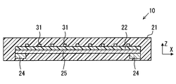
- FIG. 3 is a cross-sectional view taken along line III-III in FIG.
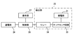
- It is a block diagram which simplifies and shows the electrical structure of a heater apparatus.
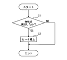
- It is a flowchart which shows the process of the control part of a heater apparatus.
- It is a graph which shows the relationship between the surface temperature of the main-body part of a heater apparatus, and time passage.
- It is sectional drawing which simplifies and shows the heater apparatus before an object contacts. It is sectional drawing which simplifies and shows the heater apparatus in the state which the object is contacting.
- the heater device 10 is installed in a room of a moving body such as a road traveling vehicle, a ship, and an aircraft.
- the heater device 10 constitutes a part of a room heating device.
- the heater device 10 is an electric heater that generates heat by being fed from a power source such as a battery or a generator mounted on a moving body.
- the heater device 10 is formed in a thin plate shape.
- the heater device 10 generates heat when electric power is supplied.
- the heater device 10 emits radiant heat H mainly in a direction perpendicular to the surface in order to warm an object positioned in a direction perpendicular to the surface.
- the heater device 10 is installed indoors so as to radiate radiant heat H to the feet of the occupant 12.
- the heater device 10 can be used as a device for immediately providing warmth to the occupant 12 immediately after activation of another heating device, for example.
- the heater device 10 is installed on a wall surface in the room.
- the heater device 10 is installed so as to face the occupant 12 in the assumed normal posture.
- the road traveling vehicle has a steering column 14 for supporting the handle 13.
- the heater device 10 can be installed on the lower surface of the steering column 14 so as to face the occupant 12.
- the heater device 10 extends along the XY plane defined by the axes X and Y.
- the heater device 10 has a thickness in the direction of the axis Z.
- the heater device 10 is formed in a substantially rectangular thin plate shape.
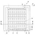
- the heater device 10 includes a main body unit 21, an insulating substrate 22, a detection unit 23, a current supply unit 24, a heat generation unit 25, and a control unit 26.
- the heater device 10 can also be referred to as a planar heater that radiates radiant heat H mainly in a direction perpendicular to the surface.
- the main body 21 has excellent electrical insulation.
- the main body portion 21 is provided so as to surround each of the plurality of heat generating portions 25, and has a thermal conductivity lower than the heat conductivity of the heat generating portion 25.
- the main body 21 has a flat plate shape, and an insulating substrate 22, a detection unit 23, an energization unit 24, and a heat generation unit 25 are built in the main body 21.
- the insulating substrate 22 is made of a resin material that provides excellent electrical insulation and withstands high temperatures.
- the surface 22 a of the insulating substrate 22 faces the radiation direction of the radiant heat H.
- the surface 22a located on one side in the thickness direction of the insulating substrate 22 is a surface that is disposed to face a part of the occupant 12 that is a heating target in the installed state of the heater device 10.
- the back surface 22 b located on the other side in the thickness direction of the insulating substrate 22 provides the back surface of the heater device 10.
- the insulating substrate 22 supports the detection unit 23 and the heat generation unit 25.
- the plurality of heat generating units 25 are connected to the energizing unit 24 and generate heat by the electric power supplied from the energizing unit 24.
- the plurality of heat generating portions 25 are distributed and arranged on the back surface 22 b of the insulating substrate 22.
- Each of the plurality of heat generating portions 25 is made of a material having high thermal conductivity.
- the heat generating portion 25 is made of an excellent electric conductor, that is, a material having a low electric resistance.
- the heat generating part 25 can be made of a metal material.
- the heat generating portion 25 is selected from a material having a thermal conductivity lower than that of copper.
- the heat generating part 25 is a metal such as an alloy of copper and tin (Cu—Sn), silver, tin, stainless steel, nickel, nichrome, or an alloy containing these metals.
- Each of the plurality of heat generating portions 25 is formed in a thin plate shape parallel to the surface of the insulating substrate 22.
- the heat generating part 25 can radiate the radiant heat H by heat supplied by energization.
- the heating part 25 can radiate the radiant heat H that makes the occupant 12, that is, a person feel warmth, by being heated to a predetermined radiation temperature.
- One heat generating portion 25 is formed in a rectangular shape extending on the axis X in the XY plane. The material and the cross-sectional dimensions of the heat generating portion 25 are defined so that the thermal resistance in the direction of the axis X is a predetermined value or less.
- the plurality of heat generating portions 25 are arranged on the back surface 22b of the insulating substrate 22 so as not to overlap each other.
- the plurality of heat generating portions 25 are arranged away from each other in the direction of the axis Y.
- the plurality of heat generating portions 25 are regularly arranged so as to occupy a predetermined area on the XY plane in the drawing.
- the pair of energization parts 24 is a rectangle extending in the direction of the axis Y, and is disposed so as to be in contact with both ends of the axis X of the plurality of heat generating parts 25 so as to be energized. Therefore, the plurality of heat generating units 25 are connected to the energizing unit 24 in parallel. A predetermined voltage is applied to both ends of the axis Y of the energization unit 24.
- the energization unit 24 is supplied with power from an external power source and supplies the supplied power to the heat generating unit 25.
- the electrical resistivity of the energizing unit 24 is set to be smaller than the electrical resistivity of the heat generating unit 25.
- the energization unit 24 is made of, for example, copper.
- the cross-sectional area of the heat generating part 25 is set to be smaller than the cross-sectional area of the energizing part 24. As a result, the energization unit 24 is prevented from generating heat even when a large current flows.
- the detection unit 23 detects an object around the main body unit 21.
- the detection unit 23 detects a change in capacitance due to an object approaching the heat generating unit 25 and detects that the object is within a predetermined range of the heat generating unit 25.
- the detection unit 23 is configured to be able to communicate with the control unit 26. When the detection unit 23 detects that the object is within the predetermined range of the heat generation unit 25, the detection unit 23 transmits the detection to the control unit 26.
- the detecting unit 23 detects that an object has contacted the surface of the main body 21 and that an object has approached the surface of the main body 21.
- the detection unit 23 includes a plurality of conductive units 31 as electrodes for detecting a change in capacitance.
- the conductive portion 31 has conductivity and is made of, for example, copper.
- the plurality of conductive portions 31 are distributed and arranged on the surface 22 a of the insulating substrate 22.
- the detection unit 23 is built in the main body unit 21 together with the heat generation unit 25. Further, the heat generating portion 25 and the conductive portion 31 are insulated by the insulating substrate 22.
- the plurality of conductive portions 31 are arranged on the surface 22a of the insulating substrate 22 so as not to overlap each other.
- the plurality of conductive portions 31 are arranged away from each other.
- the pair of conductive portions 31 extends in the direction of the axis X with an interval in the direction of the axis Y.
- the other plurality of conductive portions 31 extend in the direction of the axis Y with an interval in the direction of the axis X, and both ends are connected to the pair of conductive portions 31.
- the conductive portion 31 is arranged like a vertical stripe pattern in which ends in the direction of the axis Y are connected.
- the cross-sectional area of the conductive portion 31 is set to be smaller than the cross-sectional area of the energizing portion 31.
- Electrodes 32 are provided at the four corners of the XY plane of the conductive portion 31. Electric power is applied to the electrode 32, and a current flows through the conductive portion 31. Accordingly, when a current flows through the conductive portion 31, a uniform low-voltage electric field can be generated around the main body portion 21. As a result, the capacitance of the electrode 32 changes as the object approaches the main body 21.
- the control unit 26 can detect the approach of the object by converting this change into an electrical signal. Therefore, the detection unit 23 detects the change in capacitance through an energy field called an electric field, and detects the presence of an object in a non-contact manner.
- control unit 26 is electrically connected to the energization unit 24, the operation unit 27, and the detection unit 23.
- the operation unit 27 includes a switch for operating the heater device 10.
- the operation unit 27 may be the same as the operation switch of the vehicle air conditioner.
- the heater device 10 can be turned on / off and the set temperature can be set.
- the operation information is given to the control unit 26.
- the detection unit 23 includes a conductive unit 31, a touch sensor circuit 33, and a relay 34.
- the conductive part 31 generates an electric field as described above.
- the touch sensor circuit 33 is a circuit that is connected to the conductive portion 31 and detects a change in capacitance of the conductive portion 31.
- the touch sensor circuit 33 is also connected to the relay 34.
- the touch sensor circuit 33 detects a change in capacitance, the touch sensor circuit 33 converts the change into an electrical signal and controls the relay 34 to be turned on from off. As a result, a signal indicating a change in capacitance is given to the control unit 26 via the relay 34.
- the control unit 26 controls the power applied to the energization unit 24.
- the control unit 26 controls the power to the energization unit 24 based on the operation information. For example, the control unit 26 performs control so that the energization unit 24 supplies power when a power-on operation is performed. Further, as described above, when the signal is given from the detection unit 23, the control unit 26 determines that the object has approached or contacted.
- step S1 it is determined whether or not an object is detected by the detection unit 23. If an object is detected, the process proceeds to step S2, and if not detected, this flow ends.
- the detection of the object by the detection unit 23 determines that the object has been detected when the object is within a predetermined range of the main body unit 21, for example, when approaching or touching. Proximity indicates, for example, a state at a position away from the surface of the main body 21 within a range of several centimeters.
- step S2 since an object has been detected, control is performed so that the power supplied to the energization unit 24 is stopped, and this flow ends. Thus, when the power supplied to the energization unit 24 is stopped, the heat generation by the heat generation unit 25 is stopped.
- the control unit 26 controls the energization amount to the energization unit 24 to be smaller than the normal state.
- the control unit 26 controls energization to the energization unit 24 so as to stop energization.
- the control unit 26 controls the power so as to stop the power supply to the energization unit 24 when the change in the capacitance becomes a predetermined value or more.
- the normal state is, for example, an energization amount that becomes a set temperature set by the user.
- the tip of the finger contacts the surface of the main body 21 at time T1 (about 30 seconds) shown in FIG. Then, it turns out that temperature falls from about 90 degree
- the heat generating portion 25 has a thin shape and is surrounded by the main body portion 21, it is difficult for heat to be transmitted from the heat generating portion 25 to the contact portion. Therefore, although the finger is in contact from time T1 to time T2 (about 4 minutes 20 seconds), the temperature rise is low. When the finger is removed from the main body 21 at time T2, it can be seen that the temperature rises in a short time.
- the control unit 26 energizes the energization unit 24 to stop the energization amount to the energization unit 24. Control. Therefore, the power supply is stopped when at least the object comes into contact with the main body portion 21, but as shown in FIG. 6, the surface temperature is instantaneously lowered when the object comes into contact with the main body portion 21 regardless of the presence or absence of power supply. Therefore, even if the main body portion 21 is at a high temperature, the object does not become hot at the time of contact. In addition, since the power supply is stopped thereafter, it is possible to reliably prevent the object from becoming hot even if the contact continues. In other words, since the contact portion temperature of the main body portion 21 is lowered by turning off the power, heat transfer to the object can be prevented.
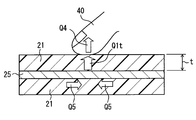
- FIGS. 7 and 8 heat transfer before and after contact with the finger 40 will be described with reference to FIGS. 7 and 8 and mathematical expressions. 7 and 8, in order to explain the heat transfer direction, the conductive portion 31 and the insulating substrate 22 are omitted, and only the heat generating portion 25 and the main body portion 21 are shown. In FIGS. 7 and 8, the direction of heat transfer is indicated by arrows. It is assumed that the back surface of the main body 21 is completely insulated.
- the amount of heat transfer Q1 from the heat generating part 25 to the surface of the main body part 21 can be expressed by the following equation (1).
- the amount of heat released from the surface of the main body 21 to the outside includes a heat amount due to convection and a heat amount due to radiation.
- the amount of heat Q2 due to convection can be expressed by the following equation (2).
- the amount of heat Q3 due to radiation can be expressed by the following equation (3).
- the ambient temperature is T0
- the temperature of the heat generating portion 25 is T1
- the surface temperature of the main body portion 21 is T2.
- T3 indicates the surface temperature of the heat generating portion 25 before contact.
- the amount of heat (Joule heat) generated by the heat generating portion 25 is Q0 (W / m 2 ).
- A is a cross-sectional area when the heat generating portion 25 is cut in the direction of the axis Y.
- the area of the upper part of the heat generating part 25 is S.
- the heat conductivity 25 of the heat generating part 25 is assumed to be ⁇ 1, and the heat conductivity ⁇ 2 of the main body part 21 is assumed.
- the thickness between the surface of the main body 21 and the heat generating part 25 is assumed to be t.
- the heat transfer coefficient of natural convection is h
- the emissivity is ⁇
- the Stefan-Boltzmann constant is ⁇ .
- the heat resistance R in the lateral direction of the heat generating part 25, the finger 40 (heat transmission rate of the human body) is K
- the length (unit length) of the heat generating part 25 is l.
- the calorific value Q0 of the heat generating part 25 is transmitted to the surface of the main body part 21 as it is and released outward by convection and radiation, the surface temperature of the main body part 21 becomes stable.
- the surface temperature of the main body part 21 becomes stable.
- the radiation temperature is, for example, a predetermined temperature of 60 ° C. or higher.
- the finger 40 contacts the surface of the main body 21.
- convection and radiation are at least partially prevented.
- at least a part of the heat radiation from the surface of the main body 21 is provided by heat transfer to the finger 40 that has come into contact. Therefore, when the finger 40 comes into contact, the thermal balance inside the main body 21 changes.
- the amount of heat transfer Q1t from the heat generating part 25 to the surface of the main body part 21 when the finger 40 comes into contact can be expressed by the following equation (4).
- the endothermic amount of the finger 40 in contact can be expressed by the following equation (5).
- the heat transfer amount Q5 from the side (both sides) of the heat generating part 25 accompanying the temperature drop of the contact part can be expressed by the following equation (6).
- the internal temperature of the finger 40 is T4
- the temperature T1t of the heat generating part 25 at the time of contact is T2t
- the surface temperature of the heat generating part 25 at the time of contact is T3t.
- some object for example, the finger 40
- the surface temperature decreases due to the amount of heat carried away by the finger 40 that has come into contact.
- the thermal resistance R is defined so that T2t is equal to or lower than a predetermined suppression temperature.
- the thermal resistance R can be expressed by the following equation (7).
- the suppression temperature is, for example, a predetermined temperature of 50 ° C. or lower.
- the cross-sectional shape and material of the heat generating portion 25 are selected so that the thermal resistance R shown in the equation (7) becomes a predetermined value or more. This is because when the thermal resistance R increases, the heat transfer amount Q5 decreases from the side (both sides) of the heat generating portion 25 as shown in the equation (6).
- the thermal resistance R is set to, for example, 1000 K / W or more, preferably 7000 K / W.
- the heat generating portion 25 has a width (diameter) of less than 1 mm, preferably 500 ⁇ m or less, and a height of less than 1 mm, preferably 100 ⁇ m or less.
- the heater device 10 includes the detection unit 23 that detects an object around the main body unit 21.
- the control unit 26 controls the amount of power supplied to the energization unit 24 based on the detection result of the detection unit 23. Specifically, when the detection unit 23 detects that the object is within a predetermined range of the main body unit 21, the control unit 26 sets the energization unit so that the energization amount to the energization unit 24 is smaller than the normal state. The energization to 24 is controlled. In other words, the detection unit 23 detects that an object has contacted or approached the main body unit 21, and when detecting the contact or approach, the control unit 26 reduces or stops the output of the heater device 10.
- the heat generation amount of the heat generating portion 25 can be made lower than that in the normal state. As a result, it is possible to prevent the adjacent object from generating heat by the heat generating unit 25. Therefore, it is possible to suppress the temperature of the object from rising due to the heat generating portion 25 while the object is close to or in contact with the object.
- the heat generating portion 25 is arranged such that a plurality of portions are dispersed on the surface.
- the main body portion 21 is provided so as to surround each of the plurality of heat generating portions 25, has an insulating property, and has a thermal conductivity lower than that of the heat generating portion 25. Since the heat generating portions 25 are arranged in a dispersed manner, the thermal capacity is small. Further, each heat generating portion 25 is suppressed by the main body portion 21 having a low thermal conductivity so that heat transfer from the surroundings is low. Accordingly, supply of additional heat from the surrounding main body portion 21 is suppressed to each heat generating portion 25.
- the detection unit 23 is built in the main body unit 21 together with the heat generation unit 25. Thereby, the electrode 32 of the heat generating part 25 and the detection part 23 can be shared. Moreover, since the detection part 23 and the heat generating part 25 are supported by the same insulating substrate 22, a support member can be shared. As a result, the number of parts can be reduced. Further, the heater device 10 can be miniaturized.
- the detection unit 23 detects a change in capacitance due to the object approaching the heat generating unit 25 to detect that the object is within a predetermined range of the heat generating unit 25. This makes it possible to detect the approach of an object without contact.
- the detection unit 23 includes a plurality of conductive units 31 as electrodes for detecting a change in capacitance.
- the cross-sectional area of the conductive portion 31 is smaller than the cross-sectional area of the energizing portion 24. Therefore, the heat capacity of the conductive portion 31 can be made smaller than that of the energizing portion 24. As a result, it is possible to prevent the heat quantity of the heat generating part 25 from being wasted by being transferred to the conductive part 31 and greatly reducing the heat quantity transferred to the main body part 21.
- the cross-sectional area of the heat generating portion 25 is smaller than the cross-sectional area of the energizing portion 24.
- the current-carrying unit 24 is less likely to generate heat than the heat-generating unit 25, so that the current transmitted from the current-carrying unit 24 can be prevented from being damaged by the heat generated by the current-carrying unit 24. Therefore, current can be efficiently supplied to the heat generating portion 25.
- the electrical resistivity of the energizing unit 24 is smaller than the electrical resistivity of the heat generating unit 25.
- the current-carrying unit 24 is less likely to generate heat than the heat-generating unit 25, so that the current transmitted from the current-carrying unit 24 can be prevented from being damaged by the heat generated by the current-carrying unit 24. Therefore, current can be efficiently supplied to the heat generating portion 25.
- the plurality of heat generating portions 25 are connected to the energizing portion 24 in parallel.
- a predetermined output can be obtained from a predetermined power source, for example, a 12V power source of the vehicle.
- the heat generating portion 25 and the conductive portion 31 are insulated. As a result, it is possible to prevent the current flowing through the heat generating portion 25 from flowing into the conductive portion 31 and vice versa. Therefore, it is possible to eliminate the influence of energizing the conductive portion 31 with the heat generating portion 25 and generate a predetermined electric field by the conductive portion 31.
- the insulating substrate 22 is built in the main body 21.
- the heat generating portion 25 is provided on the front surface 22 a of the insulating substrate 22, and the conductive portion 31 is provided on the back surface 22 b of the insulating substrate 22. Therefore, the heat generating portion 25 and the conductive portion 31 can be reliably insulated by the insulating substrate 22.
- the conductive portion 31 is built in the main body portion 21 together with the heat generating portion 25. Therefore, the heat generating part 25 and the conductive part 31 can be supported by the insulating substrate 22. Further, since the heat generating part 25 and the conductive part 31 are built in the main body part 21, foreign matters such as dust and dust can be prevented from adhering to the conductive part 31 and the heat generating part 25. As a result, the operations of the conductive portion 31 and the heat generating portion 25 can be stabilized.
- the detection unit 23 detects an object by detecting a change in capacitance, but is not limited to the capacitance type.
- the detection unit may be, for example, a resistive film type, a method using an ultrasonic surface acoustic wave, an optical imaging type using infrared rays, and an electromagnetic induction type.
- the detection unit is built in the main body unit 21, but the detection unit may be separate from the main body unit 21.
- the detection unit is not limited to a detection unit dedicated to the heater device 10.
- various sensors mounted on the vehicle, for example, an antitheft sensor may be shared.
- the conductive portion 31 has a striped shape, but may have a lattice shape as long as the configuration is dispersed on the surface.
Landscapes
- Engineering & Computer Science (AREA)
- Mechanical Engineering (AREA)
- Physics & Mathematics (AREA)
- Thermal Sciences (AREA)
- Chemical & Material Sciences (AREA)
- Combustion & Propulsion (AREA)
- General Engineering & Computer Science (AREA)
- Air-Conditioning For Vehicles (AREA)
- Electric Stoves And Ranges (AREA)
- Control Of Resistance Heating (AREA)
Abstract
Priority Applications (3)
| Application Number | Priority Date | Filing Date | Title |
|---|---|---|---|
| CN201480019067.8A CN105075390B (zh) | 2013-03-28 | 2014-01-23 | 加热器装置 |
| DE112014001660.8T DE112014001660B4 (de) | 2013-03-28 | 2014-01-23 | Heizungsvorrichtung |
| US14/778,637 US9381789B2 (en) | 2013-03-28 | 2014-01-23 | Heater apparatus |
Applications Claiming Priority (2)
| Application Number | Priority Date | Filing Date | Title |
|---|---|---|---|
| JP2013-069337 | 2013-03-28 | ||
| JP2013069337A JP5954235B2 (ja) | 2013-03-28 | 2013-03-28 | ヒータ装置 |
Publications (1)
| Publication Number | Publication Date |
|---|---|
| WO2014155915A1 true WO2014155915A1 (fr) | 2014-10-02 |
Family
ID=51622942
Family Applications (1)
| Application Number | Title | Priority Date | Filing Date |
|---|---|---|---|
| PCT/JP2014/000332 WO2014155915A1 (fr) | 2013-03-28 | 2014-01-23 | Appareil d'élément chauffant |
Country Status (5)
| Country | Link |
|---|---|
| US (1) | US9381789B2 (fr) |
| JP (1) | JP5954235B2 (fr) |
| CN (1) | CN105075390B (fr) |
| DE (1) | DE112014001660B4 (fr) |
| WO (1) | WO2014155915A1 (fr) |
Cited By (5)
| Publication number | Priority date | Publication date | Assignee | Title |
|---|---|---|---|---|
| JP2017098048A (ja) * | 2015-11-23 | 2017-06-01 | 株式会社デンソー | ヒータシステム |
| CN107926081A (zh) * | 2015-09-15 | 2018-04-17 | 株式会社电装 | 加热器装置 |
| WO2019078090A1 (fr) * | 2017-10-17 | 2019-04-25 | 株式会社デンソー | Dispositif de chauffage |
| JP2019074303A (ja) * | 2017-10-17 | 2019-05-16 | 株式会社デンソー | ヒータ装置 |
| US10661634B2 (en) | 2015-04-15 | 2020-05-26 | Denso Corporation | Heater device |
Families Citing this family (19)
| Publication number | Priority date | Publication date | Assignee | Title |
|---|---|---|---|---|
| DE102012020870B3 (de) * | 2012-10-24 | 2014-02-13 | Audi Ag | Heizvorrichtung für den Fahrzeuginnenraum eines Fahrzeugs |
| DE102013214554A1 (de) * | 2013-07-25 | 2015-01-29 | Bayerische Motoren Werke Aktiengesellschaft | Verfahren zum Heizen des Innenraums eines Fahrzeugs |
| JP6447245B2 (ja) | 2014-07-25 | 2019-01-09 | 株式会社デンソー | 輻射ヒータ装置 |
| KR102262142B1 (ko) * | 2015-01-19 | 2021-06-10 | 현대자동차주식회사 | 차량용 복사열 히터 |
| WO2016117376A1 (fr) * | 2015-01-19 | 2016-07-28 | 株式会社デンソー | Dispositif de chauffage |
| WO2016117375A1 (fr) * | 2015-01-22 | 2016-07-28 | 株式会社デンソー | Dispositif de chauffage |
| US10946722B2 (en) * | 2015-08-27 | 2021-03-16 | Denso Corporation | Heater device |
| WO2017104343A1 (fr) * | 2015-12-17 | 2017-06-22 | 株式会社デンソー | Dispositif de chauffage |
| CN108476559B (zh) * | 2016-01-25 | 2021-04-09 | 株式会社电装 | 加热器装置 |
| JP6528705B2 (ja) | 2016-03-11 | 2019-06-12 | 株式会社デンソー | 輻射ヒータ装置 |
| DE102016215548A1 (de) * | 2016-08-18 | 2018-02-22 | Bayerische Motoren Werke Aktiengesellschaft | Heizsystem mit einer Strahlungsheizeinrichtung für ein Kraftfahrzeug und Verfahren zum Betreiben einer Strahlungsheizeinrichtung |
| WO2018099503A1 (fr) * | 2016-11-30 | 2018-06-07 | Gentherm Gmbh | Système pour réguler la température d'au moins une surface en fonction des besoins |
| JP2019046786A (ja) | 2017-09-04 | 2019-03-22 | 株式会社デンソー | ヒータ装置 |
| JP6919605B2 (ja) * | 2018-03-13 | 2021-08-18 | 株式会社デンソー | ヒータ装置 |
| JP2019184171A (ja) * | 2018-04-11 | 2019-10-24 | 株式会社デンソー | ヒータ装置 |
| FR3080582B1 (fr) * | 2018-04-25 | 2020-04-24 | Faurecia Sieges D'automobile | Dossier de siege avec panneau chauffant |
| JP7135558B2 (ja) * | 2018-08-07 | 2022-09-13 | 株式会社デンソー | ヒータ装置 |
| JP7207272B2 (ja) | 2019-11-18 | 2023-01-18 | 株式会社デンソー | ヒータ装置 |
| WO2022245145A1 (fr) * | 2021-05-21 | 2022-11-24 | 한온시스템 주식회사 | Dispositif de chauffage de véhicule |
Citations (4)
| Publication number | Priority date | Publication date | Assignee | Title |
|---|---|---|---|---|
| JPS62156703U (fr) * | 1986-03-27 | 1987-10-05 | ||
| JPS63127032A (ja) * | 1986-11-18 | 1988-05-30 | Matsushita Electric Ind Co Ltd | 電気スト−ブ |
| JP2005135692A (ja) * | 2003-10-29 | 2005-05-26 | Kyocera Corp | セラミックヒータ |
| JP2010156993A (ja) * | 2004-06-16 | 2010-07-15 | Mitsubishi Pencil Co Ltd | 定着用ヒータとその製造方法 |
Family Cites Families (11)
| Publication number | Priority date | Publication date | Assignee | Title |
|---|---|---|---|---|
| DE102005055003A1 (de) | 2005-11-18 | 2007-05-24 | Bayerische Motoren Werke Ag | Verfahren zum Steuern der Scheibenbeheizung in einem Kraftfahrzeug |
| JP4902283B2 (ja) | 2006-07-13 | 2012-03-21 | アイシン精機株式会社 | シートヒータ |
| JP5515201B2 (ja) | 2007-03-29 | 2014-06-11 | パナソニック株式会社 | 車両用暖房装置 |
| JP5359004B2 (ja) | 2007-04-19 | 2013-12-04 | パナソニック株式会社 | 暖房装置付き座席 |
| JP5433387B2 (ja) * | 2009-11-30 | 2014-03-05 | 株式会社日立製作所 | 車両用機器冷却暖房システム |
| JP2011153746A (ja) | 2010-01-26 | 2011-08-11 | Panasonic Electric Works Co Ltd | 輻射暖房パネルシステム |
| JP2012056531A (ja) | 2010-09-13 | 2012-03-22 | Denso Corp | 車両用輻射熱暖房装置 |
| JP5640839B2 (ja) | 2011-03-16 | 2014-12-17 | 株式会社デンソー | 車両用暖房装置 |
| US20120234932A1 (en) | 2011-03-16 | 2012-09-20 | Denso Corporation | Vehicular heating system |
| JP2012228896A (ja) | 2011-04-25 | 2012-11-22 | Denso Corp | 車両用輻射熱暖房装置 |
| JP5895805B2 (ja) | 2012-05-23 | 2016-03-30 | 株式会社デンソー | 輻射ヒータ装置 |
-
2013
- 2013-03-28 JP JP2013069337A patent/JP5954235B2/ja active Active
-
2014
- 2014-01-23 CN CN201480019067.8A patent/CN105075390B/zh active Active
- 2014-01-23 DE DE112014001660.8T patent/DE112014001660B4/de active Active
- 2014-01-23 WO PCT/JP2014/000332 patent/WO2014155915A1/fr active Application Filing
- 2014-01-23 US US14/778,637 patent/US9381789B2/en active Active
Patent Citations (4)
| Publication number | Priority date | Publication date | Assignee | Title |
|---|---|---|---|---|
| JPS62156703U (fr) * | 1986-03-27 | 1987-10-05 | ||
| JPS63127032A (ja) * | 1986-11-18 | 1988-05-30 | Matsushita Electric Ind Co Ltd | 電気スト−ブ |
| JP2005135692A (ja) * | 2003-10-29 | 2005-05-26 | Kyocera Corp | セラミックヒータ |
| JP2010156993A (ja) * | 2004-06-16 | 2010-07-15 | Mitsubishi Pencil Co Ltd | 定着用ヒータとその製造方法 |
Cited By (7)
| Publication number | Priority date | Publication date | Assignee | Title |
|---|---|---|---|---|
| US10661634B2 (en) | 2015-04-15 | 2020-05-26 | Denso Corporation | Heater device |
| CN107926081A (zh) * | 2015-09-15 | 2018-04-17 | 株式会社电装 | 加热器装置 |
| CN107926081B (zh) * | 2015-09-15 | 2021-07-09 | 株式会社电装 | 加热器装置 |
| JP2017098048A (ja) * | 2015-11-23 | 2017-06-01 | 株式会社デンソー | ヒータシステム |
| WO2019078090A1 (fr) * | 2017-10-17 | 2019-04-25 | 株式会社デンソー | Dispositif de chauffage |
| JP2019074303A (ja) * | 2017-10-17 | 2019-05-16 | 株式会社デンソー | ヒータ装置 |
| JP7110764B2 (ja) | 2017-10-17 | 2022-08-02 | 株式会社デンソー | ヒータ装置 |
Also Published As
| Publication number | Publication date |
|---|---|
| CN105075390A (zh) | 2015-11-18 |
| DE112014001660T5 (de) | 2015-12-03 |
| US20160039265A1 (en) | 2016-02-11 |
| JP5954235B2 (ja) | 2016-07-20 |
| CN105075390B (zh) | 2017-03-15 |
| JP2014190674A (ja) | 2014-10-06 |
| DE112014001660B4 (de) | 2024-02-01 |
| US9381789B2 (en) | 2016-07-05 |
Similar Documents
| Publication | Publication Date | Title |
|---|---|---|
| JP5954235B2 (ja) | ヒータ装置 | |
| JP6376286B2 (ja) | ヒータ装置 | |
| JP6288310B2 (ja) | ヒータ装置 | |
| CN106576399B (zh) | 辐射加热器装置 | |
| JP6432687B2 (ja) | ヒータ装置 | |
| CN107926081B (zh) | 加热器装置 | |
| JP7135964B2 (ja) | ヒータ装置 | |
| US11497084B2 (en) | Heater device | |
| JP6296175B2 (ja) | ヒータ装置 | |
| WO2016103598A1 (fr) | Système de chauffage/refroidissement | |
| US20200236740A1 (en) | Heater device | |
| CN113613531A (zh) | 加热器装置 | |
| US20210140644A1 (en) | Heater device | |
| WO2016013168A1 (fr) | Dispositif de chauffage à rayonnement | |
| JP6669271B2 (ja) | 輻射ヒータ装置 | |
| WO2019078090A1 (fr) | Dispositif de chauffage | |
| JP2019207753A (ja) | ヒータ装置 |
Legal Events
| Date | Code | Title | Description |
|---|---|---|---|
| WWE | Wipo information: entry into national phase |
Ref document number: 201480019067.8 Country of ref document: CN |
|
| 121 | Ep: the epo has been informed by wipo that ep was designated in this application |
Ref document number: 14773302 Country of ref document: EP Kind code of ref document: A1 |
|
| WWE | Wipo information: entry into national phase |
Ref document number: 14778637 Country of ref document: US |
|
| WWE | Wipo information: entry into national phase |
Ref document number: 112014001660 Country of ref document: DE Ref document number: 1120140016608 Country of ref document: DE |
|
| 122 | Ep: pct application non-entry in european phase |
Ref document number: 14773302 Country of ref document: EP Kind code of ref document: A1 |