WO2020195635A1 - フィルム洗浄装置および洗浄済みフィルムの製造方法 - Google Patents
フィルム洗浄装置および洗浄済みフィルムの製造方法 Download PDFInfo
- Publication number
- WO2020195635A1 WO2020195635A1 PCT/JP2020/009105 JP2020009105W WO2020195635A1 WO 2020195635 A1 WO2020195635 A1 WO 2020195635A1 JP 2020009105 W JP2020009105 W JP 2020009105W WO 2020195635 A1 WO2020195635 A1 WO 2020195635A1
- Authority
- WO
- WIPO (PCT)
- Prior art keywords
- film
- cleaning
- cleaning liquid
- roll
- drive roll
- Prior art date
- Legal status (The legal status is an assumption and is not a legal conclusion. Google has not performed a legal analysis and makes no representation as to the accuracy of the status listed.)
- Ceased
Links
Images



Classifications
-
- B—PERFORMING OPERATIONS; TRANSPORTING
- B08—CLEANING
- B08B—CLEANING IN GENERAL; PREVENTION OF FOULING IN GENERAL
- B08B11/00—Cleaning flexible or delicate articles by methods or apparatus specially adapted thereto
-
- B—PERFORMING OPERATIONS; TRANSPORTING
- B08—CLEANING
- B08B—CLEANING IN GENERAL; PREVENTION OF FOULING IN GENERAL
- B08B3/00—Cleaning by methods involving the use or presence of liquid or steam
- B08B3/02—Cleaning by the force of jets or sprays
-
- B—PERFORMING OPERATIONS; TRANSPORTING
- B08—CLEANING
- B08B—CLEANING IN GENERAL; PREVENTION OF FOULING IN GENERAL
- B08B3/00—Cleaning by methods involving the use or presence of liquid or steam
- B08B3/04—Cleaning involving contact with liquid
Definitions
- the present invention relates to a film cleaning device. Further, the present invention relates to a method for producing a washed film, in which the film is washed while being conveyed.
- a method of transporting the film As a method of transporting the film, a method is known in which the film is held by a driven roll and tension is applied in the film traveling direction by rotating the roll to transport the film.
- the film may slip against the drive roll, causing poor transport.
- a solvent and an object to be cleaned tend to remain on the film, which tends to cause transport failure. This is because there are not a few objects to be cleaned in the cleaning tank, so the objects to be cleaned once removed reattach to the film, and the objects to be cleaned remain on the surface of the film taken out from the cleaning tank. is there.
- Patent Document 1 proposes a method of removing the solution adhering to the film surface by spray-cleaning the film surface at the outlet of the cleaning tank with pure water.
- the amount of material to be cleaned that is brought into the drive roll is reduced, the slip of the film with respect to the drive roll is improved, and the followability of the film transport speed with respect to the rotation speed of the drive roll is improved, so that the tension controllability to the film is improved. It is known to suppress the occurrence of wrinkles and meandering.
- An object to be solved by the present invention is to provide a film cleaning apparatus that improves detergency and is less likely to cause wrinkles. Another object of the present invention is to produce a washed film having good detergency.
- an object of the present invention is to improve the cleaning effect of the cleaning liquid from the cleaning tank lifted to the drive roll, to clean the film surface, and to perform appropriate tension control without causing wrinkles or rupture of the film.
- An object of the present invention is to provide a cleaning device capable of increasing the transport speed.
- the cleaning apparatus of the present invention is for cleaning a film having a drive roll (the drive roll is referred to as a first drive roll) in which the film from the cleaning tank first comes into contact with the cleaning tank and downstream of the cleaning tank.
- a means for scraping off the cleaning liquid accompanying the film leaving the cleaning tank is provided at least on the film surface side that first comes into contact with the first drive roll immediately after passing through the cleaning tank.
- a means for spraying the cleaning liquid onto the film is provided between the means for scraping off the cleaning liquid and the first driving roll, and is provided at least on the film surface side that first contacts the first driving roll. It is a device.
- a film cleaning device having the following features I) to II).
- I) It has a washing tank and a drive roll on the outlet side of the washing tank.
- II) Between the washing tank and the driving roll, the inside of the washing tank with respect to the surface on the side where the film first contacts the driving roll (hereinafter, the surface is referred to as surface A) when viewed from the cleaning tank side.
- a means for scraping off the cleaning liquid accompanying the surface and a means for spraying the cleaning liquid on the surface are provided in this order.
- the drive roll of I) corresponds to the first drive roll installed downstream of the washing tank. It also intends to provide various improved aspects.
- it is a method for producing a washed film that is washed while transporting the film. After passing through the film washing tank, the cleaning liquid accompanying the film is scraped off from the washing tank, and then the cleaning liquid is sprayed onto the film.
- the film is passed through the washing tank in the order of the first contacting drive roll (referred to as the first drive roll), and the scraping and the spraying cause the film to come into contact with the first drive roll.
- the first drive roll the order of the first contacting drive roll
- the scraping and the spraying cause the film to come into contact with the first drive roll.
- a method for producing a washed film which is performed on a film surface on the side.
- a step of scraping off the object to be cleaned on the film surface is provided on the surface side in contact with the first drive roll, and the film is further scraped off.
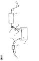
- FIG. 1 and 2 are views showing the steps used by the cleaning apparatus of the present invention for the film to be conveyed.
- the continuously supplied film 1, the cleaning tank 2 for cleaning the film 1, the driving roll 3, and the cleaning liquid and the object to be cleaned accompanying from the inside of the cleaning tank are scraped off from the film surface.
- It includes a roll 4 as a means, a nozzle array 5 as a means for spraying a cleaning liquid, and a drying furnace 6 for drying the film.
- the drive roll indicates a drive roll (referred to as a first drive roll) to which the film leaving the cleaning tank 2 first contacts.
- the film 1 runs in the direction of the arrow. After running in the cleaning liquid of the cleaning tank 2, the film 1 rises in the air while lifting the cleaning liquid 2.
- the cleaning liquid adhering to the film 1 contains an object to be cleaned.
- the film 1 comes into contact with the roll 4, which is a means for scraping off, and the cleaning liquid containing the object to be cleaned is scraped off. This is because the gap between the film 1 and the roll 4 gradually narrows until the film 1 approaches and comes into contact with the roll 4, so that the cleaning liquid is scraped off so as to flow downstream.
- the traveling direction is changed by the roll 4 to reach the next roll 4.
- the contact surfaces of the first roll 4 and the film 1 of the second roll 4 are opposite to each other. The cleaning liquid containing the object to be cleaned adhering to the film 1 is scraped off by the second roll 4.
- the film 1 passes through the nozzle array 5 for spraying the cleaning liquid and reaches the first drive roll 3. Since the cleaning liquid and the object to be cleaned are reduced in the film 1, slippage of the film is suppressed, and the film 1 runs stably following the rotation speed of the first drive roll 3.
- the nozzle array 5 is arranged on the surface (surface A) on the side where the film 1 first contacts the first drive roll 3 when viewed from the cleaning tank 2 side.
- the roll 4 which is a scraping means, efficiently removes the cleaning liquid including the object to be cleaned lifted from the cleaning tank before spraying the cleaning liquid. Therefore, even if the cleaning liquid is sprayed further downstream, the first drive roll 3 The slippage of the film on the film can be suppressed.
- the film 1 continuously supplied, the coating machine 8 for coating the surface of the film, the cleaning tank 2 for cleaning the film 1 after coating, and the first drive roll. 3. It is provided with a roll 4 which is a means for scraping off the cleaning liquid and an object to be cleaned accompanying from the inside of the cleaning tank, a nozzle array 5 which is a means for spraying the cleaning liquid, and a drying furnace 6 for drying the film.
- a roll 4 which is a means for scraping off the cleaning liquid and an object to be cleaned accompanying from the inside of the cleaning tank
- a nozzle array 5 which is a means for spraying the cleaning liquid
- a drying furnace 6 for drying the film.
- the object to be cleaned is a substance contained in the cleaning liquid to be cleaned that is attached to the film 1.
- the film 1 refers to a film, a coating layer on the surface of the film, and a laminate layer.
- the object to be cleaned is a substance extracted from the film substrate or a part of a coating agent processed on the surface of the film substrate, which is a substance to be cleaned and removed from the film substrate.
- the cleaning liquid that accompanies the film includes dust floating in the cleaning tank contained in the cleaning liquid, dust that has fallen off from the film, foreign substances such as film pieces, and a low-volatile liquid contained in the film.
- examples include foreign objects (dust of the core used for the film core, fibers of work clothes) that are not a part of the film or coating liquid.
- foreign objects dust of the core used for the film core, fibers of work clothes
- additives such as plasticizers contained in the coating liquid can be mentioned.
- the solvent used in the coating liquid examples include a good solvent that can dissolve a fluorine-containing resin and can be miscible (compatible with an arbitrary concentration) with a poor solvent (phase separation liquid) such as water.
- a porous substrate coated with such a good solvent and a coating liquid containing a fluorine-containing resin dissolved in the good solvent is introduced into a cleaning tank filled with a cleaning liquid composed of a poor solvent, it is contained in the coating film.
- the resin and the good solvent are phase-separated, and the resin is solidified to form a porous layer.
- the concentration of the fluorine-containing resin in the coating liquid is preferably in the range of 2% by weight to 7% by weight, more preferably in the range of 3% by weight to 6% by weight.
- the coating thickness can be set to 5 ⁇ m to 25 ⁇ m (one side).
- the variation in the width direction of the coating thickness is preferably ⁇ 10% or less.
- the drive roll is a roll provided with a drive motor for transporting the film.
- the cleaning device of the present invention includes a first drive roll 3 on the outlet side of the cleaning tank 2.
- the first drive roll 3 when the film is conveyed in the cleaning tank 2, frictional resistance with the cleaning liquid is applied to the film, so that a tension difference is generated between the outlet side and the entrance side of the cleaning tank 2.
- the tension on the inlet side of the cleaning tank 2 is lower than that on the outlet side.
- the first drive roll 3 is a drive roll that the film coming out of the washing tank comes into contact with first, and is used to compensate for the above-mentioned tension difference.
- the tension is low, the film may loosen, meander, and wrinkle. Therefore, it is important to transport the film by the drive roll at a tension and speed that does not cause wrinkles, sagging, or meandering of the film.
- a nip roll is a pair or a plurality of pairs of rolls that sandwich and convey the film, and may be composed of two drive rolls.
- a free rotation roll that comes into contact with one drive roll and is driven by the drive roll. It may be a combination with.
- the first drive roll is integrated with the washing tank on the same pedestal, but it can also be arranged as a separate body.
- the cleaning tank is a step of transporting the film in the liquid to clean the object to be cleaned, which adheres to the film surface or is contained in the film itself or the coating layer provided on the film surface. Pure water, a solvent, or the like is generally used as the cleaning liquid, but there is no particular limitation as long as the purpose of cleaning can be achieved.
- the scraping step is a step of scraping off the cleaning liquid and the object to be cleaned accompanying the film taken out from the cleaning tank, and is performed by using the scraping means 4. That is, the scraping step of the object to be cleaned is performed by using the scraping step 4 applied when scraping the cleaning liquid and the object to be cleaned accompanying the film taken out from the cleaning tank.
- a doctor blade, an air nozzle, a roll, or the like can be used to obtain a uniform scraping effect in the width direction of the film.
- There is no particular limitation as long as the object to be cleaned can be physically removed as long as the conveyed film is not damaged. Since the scraping efficiency is high, it is preferable to use a means for removing the cleaning liquid and the object to be cleaned by directly contacting the film.
- freeroll for film is a method that has the lowest concern about wrinkles and film rupture, simplifies the apparatus, and can obtain a uniform scraping effect in the film width direction. It is preferable that the film is held by a roll (a roll that rotates when it comes into contact with the film but is not driven by a motor or the like) and scraped off.
- the free roll has a large roll diameter because a larger area of the film in contact with the free roll enables efficient scraping.
- the cleaning liquid spraying process In the step of spraying the cleaning liquid, it is preferable to use a shower nozzle or the like so that the cleaning liquid uniformly hits the film 1.
- the shower shape generally includes a cylindrical type, a spray type, a fan type, and the like. From the results of the studies conducted by the inventors so far, it is determined that the cleaning effect is determined by the collision pressure of the cleaning liquid that hits the film when cleaning the film surface or the object to be cleaned that has penetrated into the porous membrane such as the battery separator. I know it.
- a shower nozzle that gives a fan-shaped shower shape from the viewpoint that the collision pressure of the cleaning liquid that hits the film at a constant flow rate is high and the shower cleaning liquid is uniformly applied in the film width direction.
- the reason why it is preferable to apply the shower uniformly is that if the shower is not applied uniformly, wrinkles or the like may occur on the film, causing poor transportation and causing poor appearance of the film product.
- the collision pressure depends on the discharge pressure, the spraying method, and the distance between the films.
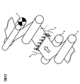
- FIG. 3 shows a spraying means for spraying the cleaning liquid.
- the means 5 for spraying the cleaning liquid uses a nozzle array that sprays the cleaning liquid in a fan-shaped shower shape, and is provided so as to hit the entire width of the film 1.
- the first drive roll 3 that first contacts the film from the outlet side of the cleaning tank 2 is not a nip roll but a structure in which the drive roll contacts only one side of the film, cleaning is performed. It is preferable to spray the cleaning liquid on the surface (surface A) on the side where the film first contacts the first drive roll when viewed from the tank side.
- the cleaning liquid When the first drive roll 3 comes into contact with both sides of the film like a nip roll, it is preferable to spray the cleaning liquid on both sides of the film when viewed from the cleaning tank side.
- a means for spraying the cleaning liquid a plurality of nozzles for blowing out the cleaning liquid in a fan shape in the width direction of the film to be conveyed are provided, and each nozzle is at equal intervals and with the cleaning liquid blown out from the nozzles on the film surface. It is preferable that the width of the overlapping with the cleaning liquid blown out from the adjacent nozzles is 5% or more and 50% or less. With such a configuration, it becomes easy to obtain a uniform surface pressure and efficient cleaning. Is possible.
- FIG. 4 is a front view of one of the nozzles that injects the cleaning liquid in a fan shape.
- the cleaning effect cannot be obtained if the cleaning liquid colliding with the film 1 does not collide in the width direction of the film 1, so that the width of the film 1 is set.
- the cleaning liquid that collides with the direction preferably hits the entire width of the film 1.
- the spread angle of the injection shape 10 is such that the width of the injection shape 10 overlaps with the cleaning liquid ejected from the adjacent nozzles so that the cleaning liquids collide evenly in the entire width direction of the film 1. It is preferable to set the number of nozzles 9 so as to be 5% or more and 50% or less, and to cover the entire width of the film.
- the distance between the film 1 and the means 9 for spraying the cleaning liquid is set by considering the degree of overlap between the cleaning liquid blown from the adjacent nozzles and the fan-shaped spreading angle of the shower nozzle, and the distance at which the cleaning liquid hits the film 1 evenly. It is preferable to do so.
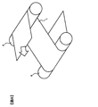
- FIG. 5 illustrates the positional relationship between the film 1 and the means 5 for spraying the cleaning liquid.
- FIG. 5 is a cross-sectional view seen from the direction perpendicular to the longitudinal direction of the film.
- a nozzle array provided with a plurality of nozzles for injecting cleaning liquid in a fan shape in the film width direction extends toward the back of the paper in FIG.
- the angle of the cleaning liquid blowing hole with respect to the film transport direction in the means for spraying the cleaning liquid is related to the collision pressure of the cleaning liquid that hits the film.
- the angle at which the collision pressure increases with respect to the film surface is effective for cleaning the object to be cleaned by applying it to the film surface from the normal direction. From this, it is preferable that the temperature is within the range of 60 ° or more and 120 ° or less with respect to the transport direction of the film.
- the angle with respect to the transport direction of the film is an angle obtained on a plane perpendicular to the film surface, including the transport direction of the film.
- the transport direction of the film surface is 0 ° and the angle between the film and the cleaning liquid 10 sprayed from the nozzle array is within the range of 60 ° or more and 120 ° or less. From the viewpoint of obtaining a high cleaning effect, it is preferably in the range of 80 ° or more and 100 ° or less.
- the collision pressure of the cleaning liquid sprayed from the cleaning liquid spraying means 5 against the film is preferably 0.05 MPa to 0.50 MPa at a transport speed of 5 m / min to 300 m / min.
- the means 4 for scraping off the cleaning liquid and the means 5 for spraying the cleaning liquid are arranged between the outlet side of the cleaning tank 2 and the first drive roll 3, and the film is the first when viewed from the cleaning tank side. It is arranged in this order so as to act on the surface (surface A) on the side that first contacts the drive roll 3 of 1. This is to prevent the object to be cleaned accompanying from the washing tank from reaching the first drive roll 3.
- the present invention it is preferable to further provide means 4 for scraping off the cleaning liquid and means 5 for spraying the cleaning liquid so as to act on the surface opposite to the surface A. That is, in the present invention, the means 4 for scraping off the cleaning liquid and the means 5 for spraying the cleaning liquid are at least arranged toward the surface side of the first drive roll 3 with which the film first comes into contact after passing through the cleaning tank. A means 4 for scraping off the cleaning liquid in the order of being closer to the cleaning tank is arranged in the film transport direction, followed by a means 5 for spraying the cleaning liquid.
- the means for scraping off the cleaning liquid and the means for spraying the cleaning liquid are films. It is preferable that the film is provided so as to face both sides of the.
- FIG. 2 shows an example in which a coating machine such as a dip coat head is used.
- the coating machine is preferably capable of applying a coating liquid having a viscosity of 10 mPa ⁇ s or more and 3000 mPa ⁇ s or less on one side of the film with a coating thickness of 1 ⁇ m or more and 100 ⁇ m or less, and the thickness variation in the width direction is ⁇ 10%.
- the coating method is not particularly limited, and for example, dip coat, cast coat, spin coat, bar coat, spray coat, blade coat, slit die coat, gravure coat, reverse coat, lip direct coat, comma coat, screen.
- wet coating methods such as printing, mold coating, printing transfer, and inkjet can be mentioned.
- the lip direct method, comma coat method, and dip coat method which are scraping methods suitable for high viscosity, thin film, and high speed coating, are preferable. ..
- the dip coating method is more preferable from the viewpoint that a porous layer can be formed on both sides at the same time. By adopting the dip coat method, it is possible to apply at a speed of 80 m / min or more.
- the film transport speed can be set in the range of, for example, 5 m / min to 300 m / min, and is appropriately set according to the coating method from the viewpoints of productivity and uniformity of coating film thickness. can do.
- the film used in the present invention is not particularly limited as long as it has a film-like shape, and examples thereof include a plastic film, a non-woven fabric sheet, and a carbon sheet.
- examples of the plastic film include polyester films such as polyethylene terephthalate and polyethylene nitrate, polyolefin films such as polypropylene, polyethylene and composite films thereof, polyimide films, polyamides, and polyphenylene sulfide films.
- it can be preferably a porous base material.
- porous medium Demand for separator films for lithium-ion batteries has been increasing in recent years, and their functionality is increasing, such as by providing a coat layer with a functional layer coated on the surface.
- Most of the porous composite films (separator films) are porous from the viewpoint of ionic conductivity. For this reason, a solvent such as an organic solvent is often used in the manufacturing process of the porous film and the forming process of the coat layer, and foreign substances and solid desorbed substances from the film are likely to occur.
- the cleaning apparatus of the present invention is preferably used in those using such a porous material, particularly in a separator film.
- As the porous substrate it is preferable to use a polyolefin porous membrane.
- polyethylene and polypropylene are preferable. It may also be a single product or a mixture of two or more different polyolefin resins, for example a mixture of polyethylene and polypropylene.
- the polyolefin may be a homopolymer or a copolymer.
- polyethylene may be a homopolymer of ethylene, a copolymer containing another ⁇ -olefin unit, or polypropylene. May be a homopolymer of propylene or a copolymer containing another ⁇ -olefin unit.
- the porous substrate may be a single-layer film or a laminated film composed of two or more layers.
- the thickness of the porous substrate is preferably in the range of 3 ⁇ m to 25 ⁇ m, more preferably in the range of 3 to 20 ⁇ m.
- the porosity of the porous substrate is preferably in the range of 30 to 70%, more preferably in the range of 35 to 60%.
- the overall film thickness of the porous composite film can be set in the range of 4 ⁇ m to 30 ⁇ m, preferably in the range of 4 ⁇ m to 24 ⁇ m. By setting the thickness in such a range, it is possible to secure the mechanical strength and the insulating property while making the film as thin as possible.
- the functional layer of the porous composite film is preferably porous, for example, when it is used as a separator for a lithium ion battery.
- the thickness of the functional layer can be set in the range of 1 to 5 ⁇ m, preferably in the range of 1 to 4 ⁇ m, and more preferably in the range of 1 to 3 ⁇ m. By setting the thickness of the functional layer in such a range, it is possible to obtain a sufficient effect of forming the functional layer and adhesive strength with the minimum necessary thickness.
- the porous substrate was processed using the apparatus configuration shown in FIG. Specifically, a coating liquid containing a solvent of N-methyl-2-pyrrolidone (NMP) in a coating machine 8 at a transport speed of 60 m / min for a separator (thickness 7 ⁇ m) of a lithium ion battery having a width of 900 mm. was applied, washed in a washing tank 2 containing pure water, and dried in a drying oven 6.
- NMP N-methyl-2-pyrrolidone
- the cleaning liquid As a means for spraying the cleaning liquid, pure water is used as the cleaning liquid, and MVVP115 manufactured by Ikeuchi Co., Ltd. is used as the shower nozzle for discharging the cleaning liquid.
- the cleaning liquid from the adjacent cleaning nozzles at the landing point at equal intervals in the direction parallel to the film width direction.
- the overlap with and is set to 5% when the reachable width of the cleaning liquid by each nozzle is 100%, and the number of nozzles is provided so that the cleaning liquid reaches the entire width of the film. As shown in FIG. 3, the cleaning liquid was sprayed beyond the film width.
- a pressure gauge (Nagano Keiki Co., Ltd. "ordinary pressure gauge AA10-160") is installed just before the shower nozzle in the piping path from the gear pump to the shower nozzle, and a ball valve is installed in the piping path between the gear pump and the pressure gauge. Then, the value at which the flow rate was changed was read with a pressure gauge and used as the shower discharge pressure.
- a flow meter (Keyence Co., Ltd. "Clamp-on type flow meter FD-Q15A / 20A") is installed just before the shower nozzle in the piping path from the gear pump to the shower nozzle, and a ball valve is connected to the piping path between the gear pump and the flow meter. was installed, and the value at which the flow rate was changed was read with a flow meter and used as the shower flow rate.
- Shower angle It is the angle formed by the cleaning liquid discharged from the shower nozzle and the film, and is obtained as the angle formed by the cleaning liquid and the film when viewed from the downstream side in the film transport direction on a plane parallel to the film transport direction and perpendicular to the film surface ( (See FIG. 5). The same applies to the back surface of the film, and when the shower angle is an acute angle, the cleaning liquid is sprayed from the downstream side to the upstream side of the film.
- the separator film immediately before passing through the first drive roll 3 was sampled, and the amount of the object to be cleaned (NMP) remaining on the film was determined and evaluated.
- the residual NMP contained in the sampled separator film was determined by the following measuring method.
- sample preparation> To prepare the standard solution, weigh the standard product (0.0104 g) in a measuring flask (10 mL), and then use N, N-dimethylacetamide (DMAc) to formulate the standard stock solution (concentration: 1040 ⁇ g / mL). , DMAc was diluted to prepare a standard solution for calibration lines.
- DMAc N, N-dimethylacetamide
- sample solution cut the sample of the separator film just before passing through the first drive roll 3 into 1 cm ⁇ 1 cm, weigh the sample (0.1 g) into a 20 mL screw tube, and add 10 mL of DMAc.
- the sample solution was prepared by covering it with a lid, immersing it (24 hours), and sonicating it (30 minutes).
- Examples 1 to 4 As shown in Table 1, the shower flow rate was changed to 5, 7, 9, 10 L / min, the shower discharge pressure was changed to 0.05, 0.10, 0.13, 0.16 MPa, the shower angle was 90 °, and the scraping process was performed. The coating was carried out under certain conditions. As a result, it was possible to obtain a separator film having a smaller residual NMP amount when the shower flow rate was 10 L / min and the shower discharge pressure was 0.16 MPa than when the shower flow rate was 5 L / min and the shower discharge pressure was 0.05 MPa.
- Examples 5, 6 and 7 The shower angle was changed to 120 ° (Example 5), 60 ° (Example 6), and 30 ° (Example 7), respectively, the shower flow rate was 10 L / min, the shower discharge pressure was 0.16 MPa, and scraping was performed.
- the coating was carried out under the condition of having a process. As a result, it was possible to obtain a separator film having a smaller residual NMP amount when the shower angle was 90 ° than when the shower angles were 30 °, 60 ° and 120 °.
- Comparative Example 2 A separator film was produced in the same manner as in Example 1 except that there was no shower in the spraying step and no scraping step.
Landscapes
- Cleaning By Liquid Or Steam (AREA)
Priority Applications (1)
| Application Number | Priority Date | Filing Date | Title |
|---|---|---|---|
| JP2020517601A JPWO2020195635A1 (https=) | 2019-03-27 | 2020-03-04 |
Applications Claiming Priority (2)
| Application Number | Priority Date | Filing Date | Title |
|---|---|---|---|
| JP2019-061088 | 2019-03-27 | ||
| JP2019061088 | 2019-03-27 |
Publications (1)
| Publication Number | Publication Date |
|---|---|
| WO2020195635A1 true WO2020195635A1 (ja) | 2020-10-01 |
Family
ID=72608590
Family Applications (1)
| Application Number | Title | Priority Date | Filing Date |
|---|---|---|---|
| PCT/JP2020/009105 Ceased WO2020195635A1 (ja) | 2019-03-27 | 2020-03-04 | フィルム洗浄装置および洗浄済みフィルムの製造方法 |
Country Status (2)
| Country | Link |
|---|---|
| JP (1) | JPWO2020195635A1 (https=) |
| WO (1) | WO2020195635A1 (https=) |
Cited By (5)
| Publication number | Priority date | Publication date | Assignee | Title |
|---|---|---|---|---|
| CN114289380A (zh) * | 2021-12-29 | 2022-04-08 | 山东金泰恒盛新材料科技有限公司 | 一种石头纸清洁装置及其清洁方法 |
| CN114370753A (zh) * | 2022-01-18 | 2022-04-19 | 深圳市亿线通电子有限公司 | 一种用于高防水导电膜的生产设备 |
| WO2022102406A1 (ja) * | 2020-11-11 | 2022-05-19 | 芝浦機械株式会社 | 抽出乾燥装置 |
| CN116493304A (zh) * | 2023-06-30 | 2023-07-28 | 宁德时代新能源科技股份有限公司 | 清洗装置、除杂系统和清洗方法 |
| CN117682353A (zh) * | 2023-10-30 | 2024-03-12 | 重庆石墨烯研究院有限公司 | 石墨烯薄膜收卷系统 |
Citations (6)
| Publication number | Priority date | Publication date | Assignee | Title |
|---|---|---|---|---|
| US3656325A (en) * | 1967-08-01 | 1972-04-18 | Hunt Co Rodney | Apparatus for wet processing a continuous length of moving material |
| JPH09314084A (ja) * | 1996-05-27 | 1997-12-09 | Sony Corp | シート状材料洗浄方法及びシート状材料洗浄装置 |
| JP2002316116A (ja) * | 2001-04-23 | 2002-10-29 | Toppan Printing Co Ltd | プラスチックフィルムの洗浄装置およびそれを用いた洗浄方法 |
| JP2007270321A (ja) * | 2006-03-31 | 2007-10-18 | Fujifilm Corp | 洗浄装置、めっき被膜付きフィルムの製造装置、洗浄方法及びめっき被膜付きフィルムの製造方法 |
| JP2013181180A (ja) * | 2012-02-29 | 2013-09-12 | Sumitomo Metal Mining Co Ltd | 電気めっきの前処理方法及び該前処理方法を含んだ電気めっき方法による銅張積層樹脂フィルムの製造方法 |
| JP2017001009A (ja) * | 2015-06-11 | 2017-01-05 | 住友化学株式会社 | フィルム製造方法 |
-
2020
- 2020-03-04 JP JP2020517601A patent/JPWO2020195635A1/ja active Pending
- 2020-03-04 WO PCT/JP2020/009105 patent/WO2020195635A1/ja not_active Ceased
Patent Citations (6)
| Publication number | Priority date | Publication date | Assignee | Title |
|---|---|---|---|---|
| US3656325A (en) * | 1967-08-01 | 1972-04-18 | Hunt Co Rodney | Apparatus for wet processing a continuous length of moving material |
| JPH09314084A (ja) * | 1996-05-27 | 1997-12-09 | Sony Corp | シート状材料洗浄方法及びシート状材料洗浄装置 |
| JP2002316116A (ja) * | 2001-04-23 | 2002-10-29 | Toppan Printing Co Ltd | プラスチックフィルムの洗浄装置およびそれを用いた洗浄方法 |
| JP2007270321A (ja) * | 2006-03-31 | 2007-10-18 | Fujifilm Corp | 洗浄装置、めっき被膜付きフィルムの製造装置、洗浄方法及びめっき被膜付きフィルムの製造方法 |
| JP2013181180A (ja) * | 2012-02-29 | 2013-09-12 | Sumitomo Metal Mining Co Ltd | 電気めっきの前処理方法及び該前処理方法を含んだ電気めっき方法による銅張積層樹脂フィルムの製造方法 |
| JP2017001009A (ja) * | 2015-06-11 | 2017-01-05 | 住友化学株式会社 | フィルム製造方法 |
Cited By (8)
| Publication number | Priority date | Publication date | Assignee | Title |
|---|---|---|---|---|
| WO2022102406A1 (ja) * | 2020-11-11 | 2022-05-19 | 芝浦機械株式会社 | 抽出乾燥装置 |
| JP7072623B1 (ja) | 2020-11-11 | 2022-05-20 | 芝浦機械株式会社 | 抽出乾燥装置 |
| JP2022080319A (ja) * | 2020-11-11 | 2022-05-30 | 芝浦機械株式会社 | 抽出乾燥装置 |
| CN114289380A (zh) * | 2021-12-29 | 2022-04-08 | 山东金泰恒盛新材料科技有限公司 | 一种石头纸清洁装置及其清洁方法 |
| CN114370753A (zh) * | 2022-01-18 | 2022-04-19 | 深圳市亿线通电子有限公司 | 一种用于高防水导电膜的生产设备 |
| CN116493304A (zh) * | 2023-06-30 | 2023-07-28 | 宁德时代新能源科技股份有限公司 | 清洗装置、除杂系统和清洗方法 |
| CN116493304B (zh) * | 2023-06-30 | 2023-11-03 | 宁德时代新能源科技股份有限公司 | 清洗装置、除杂系统和清洗方法 |
| CN117682353A (zh) * | 2023-10-30 | 2024-03-12 | 重庆石墨烯研究院有限公司 | 石墨烯薄膜收卷系统 |
Also Published As
| Publication number | Publication date |
|---|---|
| JPWO2020195635A1 (https=) | 2020-10-01 |
Similar Documents
| Publication | Publication Date | Title |
|---|---|---|
| WO2020195635A1 (ja) | フィルム洗浄装置および洗浄済みフィルムの製造方法 | |
| US20060081176A1 (en) | Surfactant applicator for solution casting system and method of use to produce a film | |
| JP6303005B2 (ja) | 塗布装置及び多孔性のイミド系樹脂膜製造システム | |
| US7943200B2 (en) | Method of curtain coating | |
| JP5279594B2 (ja) | 塗布装置 | |
| WO2006095669A1 (ja) | 塗布装置、塗布方法および塗膜を有するウェブの製造方法 | |
| JP2010094577A (ja) | フイルム状基材の洗浄方法及び洗浄装置 | |
| TWI701292B (zh) | 醯亞胺系樹脂膜製造系統及醯亞胺系樹脂膜製造方法 | |
| JP2008253862A (ja) | ウエブ状被洗浄物の洗浄方法及び装置 | |
| JP7324373B2 (ja) | スプレー塗布装置およびスプレー塗布方法 | |
| US9579683B2 (en) | Surface treatment apparatus | |
| JP2009195832A (ja) | 洗浄装置及び洗浄方法 | |
| JP2008260925A (ja) | セルロースアシレートフィルムの製造方法 | |
| JP2018006616A (ja) | 基板処理装置 | |
| JP2004243164A (ja) | 塗布装置および塗布方法 | |
| JP2002301417A (ja) | 塗布装置および塗布方法 | |
| TWI559432B (zh) | Substrate processing device | |
| CN104785418B (zh) | 一种涂布装置 | |
| US20050205117A1 (en) | Method and device for removing dust from surface of support | |
| JP2005270724A (ja) | 塗布装置及び塗布方法 | |
| CN101722156B (zh) | 薄膜的清洗喷嘴装置 | |
| JP5546516B2 (ja) | 塗布装置及び塗布方法 | |
| CN111512704A (zh) | 卷材的制造方法、带电控制方法以及带电控制装置 | |
| JP7169809B2 (ja) | イミド系樹脂膜製造システム、イミド系樹脂膜製造方法及びセパレータ製造方法 | |
| CN107199761A (zh) | 一种聚乙烯醇系光学膜的剥离方法 |
Legal Events
| Date | Code | Title | Description |
|---|---|---|---|
| ENP | Entry into the national phase |
Ref document number: 2020517601 Country of ref document: JP Kind code of ref document: A |
|
| 121 | Ep: the epo has been informed by wipo that ep was designated in this application |
Ref document number: 20779824 Country of ref document: EP Kind code of ref document: A1 |
|
| NENP | Non-entry into the national phase |
Ref country code: DE |
|
| 122 | Ep: pct application non-entry in european phase |
Ref document number: 20779824 Country of ref document: EP Kind code of ref document: A1 |