WO2020189247A1 - コネクタ - Google Patents
コネクタ Download PDFInfo
- Publication number
- WO2020189247A1 WO2020189247A1 PCT/JP2020/008785 JP2020008785W WO2020189247A1 WO 2020189247 A1 WO2020189247 A1 WO 2020189247A1 JP 2020008785 W JP2020008785 W JP 2020008785W WO 2020189247 A1 WO2020189247 A1 WO 2020189247A1
- Authority
- WO
- WIPO (PCT)
- Prior art keywords
- low
- pressure
- connector
- tapered
- valve seat
- Prior art date
- Legal status (The legal status is an assumption and is not a legal conclusion. Google has not performed a legal analysis and makes no representation as to the accuracy of the status listed.)
- Ceased
Links
Images




Classifications
-
- F—MECHANICAL ENGINEERING; LIGHTING; HEATING; WEAPONS; BLASTING
- F02—COMBUSTION ENGINES; HOT-GAS OR COMBUSTION-PRODUCT ENGINE PLANTS
- F02M—SUPPLYING COMBUSTION ENGINES IN GENERAL WITH COMBUSTIBLE MIXTURES OR CONSTITUENTS THEREOF
- F02M37/00—Apparatus or systems for feeding liquid fuel from storage containers to carburettors or fuel-injection apparatus; Arrangements for purifying liquid fuel specially adapted for, or arranged on, internal-combustion engines
- F02M37/0011—Constructional details; Manufacturing or assembly of elements of fuel systems; Materials therefor
- F02M37/0017—Constructional details; Manufacturing or assembly of elements of fuel systems; Materials therefor related to fuel pipes or their connections, e.g. joints or sealings
-
- F—MECHANICAL ENGINEERING; LIGHTING; HEATING; WEAPONS; BLASTING
- F02—COMBUSTION ENGINES; HOT-GAS OR COMBUSTION-PRODUCT ENGINE PLANTS
- F02M—SUPPLYING COMBUSTION ENGINES IN GENERAL WITH COMBUSTIBLE MIXTURES OR CONSTITUENTS THEREOF
- F02M55/00—Fuel-injection apparatus characterised by their fuel conduits or their venting means; Arrangements of conduits between fuel tank and pump F02M37/00
-
- F—MECHANICAL ENGINEERING; LIGHTING; HEATING; WEAPONS; BLASTING
- F02—COMBUSTION ENGINES; HOT-GAS OR COMBUSTION-PRODUCT ENGINE PLANTS
- F02M—SUPPLYING COMBUSTION ENGINES IN GENERAL WITH COMBUSTIBLE MIXTURES OR CONSTITUENTS THEREOF
- F02M55/00—Fuel-injection apparatus characterised by their fuel conduits or their venting means; Arrangements of conduits between fuel tank and pump F02M37/00
- F02M55/02—Conduits between injection pumps and injectors, e.g. conduits between pump and common-rail or conduits between common-rail and injectors
-
- F—MECHANICAL ENGINEERING; LIGHTING; HEATING; WEAPONS; BLASTING
- F16—ENGINEERING ELEMENTS AND UNITS; GENERAL MEASURES FOR PRODUCING AND MAINTAINING EFFECTIVE FUNCTIONING OF MACHINES OR INSTALLATIONS; THERMAL INSULATION IN GENERAL
- F16L—PIPES; JOINTS OR FITTINGS FOR PIPES; SUPPORTS FOR PIPES, CABLES OR PROTECTIVE TUBING; MEANS FOR THERMAL INSULATION IN GENERAL
- F16L29/00—Joints with fluid cut-off means
-
- F—MECHANICAL ENGINEERING; LIGHTING; HEATING; WEAPONS; BLASTING
- F16—ENGINEERING ELEMENTS AND UNITS; GENERAL MEASURES FOR PRODUCING AND MAINTAINING EFFECTIVE FUNCTIONING OF MACHINES OR INSTALLATIONS; THERMAL INSULATION IN GENERAL
- F16L—PIPES; JOINTS OR FITTINGS FOR PIPES; SUPPORTS FOR PIPES, CABLES OR PROTECTIVE TUBING; MEANS FOR THERMAL INSULATION IN GENERAL
- F16L37/00—Couplings of the quick-acting type
- F16L37/08—Couplings of the quick-acting type in which the connection between abutting or axially overlapping ends is maintained by locking members
- F16L37/12—Couplings of the quick-acting type in which the connection between abutting or axially overlapping ends is maintained by locking members using hooks, pawls, or other movable or insertable locking members
- F16L37/14—Joints secured by inserting between mating surfaces an element, e.g. a piece of wire, a pin, a chain
- F16L37/142—Joints secured by inserting between mating surfaces an element, e.g. a piece of wire, a pin, a chain where the securing element is inserted tangentially
-
- F—MECHANICAL ENGINEERING; LIGHTING; HEATING; WEAPONS; BLASTING
- F16—ENGINEERING ELEMENTS AND UNITS; GENERAL MEASURES FOR PRODUCING AND MAINTAINING EFFECTIVE FUNCTIONING OF MACHINES OR INSTALLATIONS; THERMAL INSULATION IN GENERAL
- F16L—PIPES; JOINTS OR FITTINGS FOR PIPES; SUPPORTS FOR PIPES, CABLES OR PROTECTIVE TUBING; MEANS FOR THERMAL INSULATION IN GENERAL
- F16L55/00—Devices or appurtenances for use in, or in connection with, pipes or pipe systems
- F16L55/04—Devices damping pulsations or vibrations in fluids
- F16L55/045—Devices damping pulsations or vibrations in fluids specially adapted to prevent or minimise the effects of water hammer
- F16L55/055—Valves therefor
Definitions
- the present invention relates to a connector.
- the low-pressure fuel supplied from the fuel tank by the low-pressure pump is pressurized by the high-pressure pump, and the pressurized high-pressure fuel is used as an internal combustion engine.
- pulsation occurs in the low-pressure pipe through which the low-pressure fuel flows due to the drive of the high-pressure pump, and therefore it is required to reduce the pulsation.
- pulsation in the low-pressure pipe becomes a problem.
- a damper mechanism is provided in order to reduce pulsation in low-pressure piping.
- a return passage for returning a part of fuel from the high-pressure pump to the low-pressure pipe side is provided, and an electromagnetic valve for opening the return passage is provided.
- An orifice is provided.
- valve body is molded by a manufacturing method such as die casting or injection molding in which a molten material is supplied into the mold, it is required to extend the life of the mold. Therefore, it is necessary to design the shape of the valve body so that the life of the mold can be extended.
- An object of the present invention is to provide a connector capable of reducing pulsation in a low-pressure pipe and extending the life of a mold by a simple structure in a fuel supply system capable of supplying high-pressure fuel. To do.
- the connector according to the present invention is a connector connected to a low pressure pipe through which the low pressure fuel flows in a fuel supply system that pressurizes the low pressure fuel supplied from the low pressure pump by the high pressure pump and supplies the high pressure fuel to the internal combustion engine. ..
- the connector is formed into a tubular shape and has a connector main body having an annular valve seat on the inner peripheral surface, and a valve body housed inside the connector main body and arranged so as to be reciprocally movable in the flow path direction of the connector main body. Be prepared.
- the valve body is formed on the outer peripheral surface, and when the high-pressure fuel does not flow back, it is axially separated from the annular valve seat of the connector body by the pressure of the low-pressure fuel and is separated from the annular valve seat of the connector body.
- a forward flow path is formed between the two, and when the high-pressure fuel flows backward, the valve seat contact surface capable of contacting the annular valve seat of the connector body and the valve seat contact surface in the radial direction with respect to the valve seat contact surface. It is provided with an orifice flow path formed inward and having a flow path cross-sectional area smaller than that of the forward flow path, and has a tapered through hole that allows the backflow of the high-pressure fuel when the high-pressure fuel flows back.
- valve body moves to the high-pressure pump side due to the pressure of the low-pressure fuel.
- valve seat contact surface of the valve body is separated from the annular valve seat of the connector body.
- a forward flow path is formed between the annular valve seat of the connector body and the valve seat contact surface. Therefore, the low-pressure fuel is supplied to the high-pressure pump side by flowing through the forward flow path.
- valve body moves to the low-pressure pump side due to the pressure of the high-pressure fuel.
- valve seat contact surface of the valve body is in contact with the annular valve seat of the connector body.
- the valve body is formed with a tapered through hole for forming an orifice flow path. Therefore, the high pressure fuel slightly flows to the low pressure pump side through the tapered through hole. The pulsation in the low pressure pipe on the low pressure pump side of the connector is reduced by the orifice flow path action by the tapered through hole.
- valve body is configured to be built into the connector.
- the valve body in the low-pressure pipe instead of incorporating it in the connector.
- arranging the valve body in the low pressure pipe is not as easy as arranging the valve body in the connector body. Therefore, arranging the valve body in the low-pressure pipe is not easy to design and manufacture, and leads to high cost. Therefore, by arranging the valve body inside the connector body, it is possible to easily design and manufacture the valve body, and it is possible to surely exert the pulsation reducing effect.
- a tapered through hole as an orifice flow path is formed in the valve body.
- the through hole has a small diameter
- the protrusion of the mold also has a small diameter, and the durability of the protrusion of the mold becomes an issue.
- the through hole as the orifice flow path is tapered.
- the protrusion of the mold for forming the tapered through hole is also tapered. Therefore, the mold can be designed so that the large diameter side of the tapered protrusion is the base end side and the small diameter side of the tapered protrusion is the tip side. Compared with the case where the protrusions of the mold are formed to have the same diameter over the entire length, the durability of the protrusions is improved by making the protrusions tapered. That is, the life of the mold can be extended by making the through hole of the valve body tapered.
- FIG. 1 shows the fuel supply system. It is an axial sectional view of the connector and shows the case where the valve body constituting the connector is in contact with the annular valve seat, and the left side of the figure is the first low pressure pipe (low pressure pump) side. The right side is the second low pressure pipe (high pressure pump) side.
- the retainer is located in the initial position.
- the fuel supply system 1 is a system that supplies fuel from the fuel tank 11 to the internal combustion engine 20.
- the low-pressure fuel supplied from the low-pressure pump 12 is pressurized by the high-pressure pump 16, and the pressurized high-pressure fuel is supplied to the internal combustion engine 20.
- the fuel supply system 1 includes a fuel tank 11, a low-pressure pump 12, a pressure regulator 13, a first low-pressure pipe 14, a connector 15, a high-pressure pump 16, a high-pressure pipe 17, a common rail 18, an injector 19, and an internal combustion engine 20.
- the low-pressure pump 12 is arranged inside the fuel tank 11, and for example, the first end of the first low-pressure pipe 14 made of resin is connected to the discharge side of the low-pressure pump 12. That is, the low-pressure pump 12 pumps the fuel stored in the fuel tank 11 to the first low-pressure pipe 14 side.
- the pressure regulator 13 is arranged in the fuel tank 11 on the low pressure pump 12 side of the first low pressure pipe 14. The pressure regulator 13 regulates the low-pressure fuel flowing through the first low-pressure pipe 14 to a constant pressure.
- the second end of the first low-pressure pipe 14 (opposite to the low-pressure pump 12) is connected to the first end of the connector 15 (first cylinder portion 31 described later).
- the second end of the connector 15 (second cylinder portion 32 described later) is connected to a second low pressure pipe 16a integrally provided with the high pressure pump 16. That is, the connector 15 connects two low-pressure pipes (first low-pressure pipe 14 and second low-pressure pipe 16a) through which low-pressure fuel flows.
- the connector 15 connects the first low-pressure pipe 14 and the second low-pressure pipe 16a, and constitutes a flow path for supplying low-pressure fuel together with the first low-pressure pipe 14 and the second low-pressure pipe 16a.
- the high-pressure pump 16 introduces constant-pressure low-pressure fuel supplied from the low-pressure pump 12 and the pressure regulator 13 via the first low-pressure pipe 14, the connector 15, and the second low-pressure pipe 16a.
- the high-pressure pump 16 pressurizes the introduced low-pressure fuel and discharges the pressurized high-pressure fuel.
- the high-pressure pump 16 includes, for example, the above-mentioned second low-pressure pipe 16a, a pump main body 16b connected to the second low-pressure pipe 16a, and a plunger 16c provided so as to be reciprocally movable in the pump main body 16b. Therefore, the low-pressure fuel introduced into the pump body 16b is pressurized by the reciprocating motion of the plunger 16c.
- the high-pressure pump 16 is not limited to the plunger 16c, and various configurations can be adopted as long as the fuel can be pressurized.
- the high-pressure pump 16 may be, for example, a mechanism linked to the operation of the internal combustion engine 20. In this case, while the internal combustion engine 20 is operating, the high-pressure pump 16 continues to operate regardless of whether or not the high-pressure fuel is discharged.
- the high-pressure pump 16 has a plunger 16c
- the high-pressure fuel pressurized by the high-pressure pump 16 is supplied to the common rail 18 via the high-pressure pipe 17.
- the common rail 18 is provided with an injector 19 corresponding to the number of cylinders of the internal combustion engine 20, and the injector 19 is mounted on the internal combustion engine 20. Therefore, the high pressure fuel is injected into the internal combustion engine 20 via the common rail 18 and the injector 19.
- the injector 19 is prevented from supplying high-pressure fuel to the internal combustion engine 20.
- the crankshafts constituting the internal combustion engine 20 continue to operate.
- the plunger 16c of the high-pressure pump 16 is operated by a cam interlocking with the crankshaft constituting the internal combustion engine 20. Therefore, even when the internal combustion engine 20 does not need to be supplied with high-pressure fuel, the plunger 16c of the high-pressure pump 16 continues to operate while the crankshaft is operating.
- the low-pressure pump 12 continues to operate, the low-pressure fuel continues to be supplied to the high-pressure pump 16 via the first low-pressure pipe 14, the connector 15, and the second low-pressure pipe 16a.
- the high-pressure pump 16 pressurizes the low-pressure fuel, but the pressurized high-pressure fuel cannot be supplied to the internal combustion engine 20 side. Therefore, a phenomenon may occur in which the high-pressure fuel pressurized by the high-pressure pump 16 flows back to the second low-pressure pipe 16a, the connector 15, and the first low-pressure pipe 14.
- the backflow of high-pressure fuel may cause pulsation in the first low-pressure pipe 14. If the first low-pressure pipe 14 vibrates due to the pulsation in the first low-pressure pipe 14, abnormal noise or the like may be generated. However, as described below, the connector 15 has a function of reducing pulsation in the first low pressure pipe 14. Therefore, the pulsation in the first low-pressure pipe 14 is reduced, and the generation of abnormal noise and the like is suppressed.
- the configuration of the connector 15 will be described with reference to FIGS. 2 and 3. As shown in FIG. 2, the connector 15 connects the first low-pressure pipe 14 and the second low-pressure pipe 16a, and allows fuel to flow between the first low-pressure pipe 14 and the second low-pressure pipe 16a. The end of the first low-pressure pipe 14 is extrapolated to the first end side of the connector 15, and the end of the second low-pressure pipe 16a is inserted to the second end side of the connector 15.
- the first low-pressure pipe 14 is formed of, for example, resin and has a thin-walled tubular shape. Therefore, the first low-pressure pipe 14 is formed so as to be deformable in diameter as compared with the connector 15.
- the second low pressure pipe 16a is formed of, for example, metal or hard resin, and is formed in a tubular shape.
- the ends of the second low-pressure pipe 16a are an annular flange 16a1 (also referred to as a bead) formed so as to project radially outward at a position separated from the tip in the axial direction, and a small diameter portion on the tip side of the annular flange 16a1. It includes a tip portion 16a2.
- the connector 15 will be described below by taking the quick connector type as an example, but the connector 15 is not limited to the quick connector type, as long as the pipes can be connected to each other. Further, the connector 15 is not limited to the configuration illustrated below in the quick connector type, and various quick connector types can be applied.
- the connector 15 includes, for example, a connector main body 30, a retainer 40, a seal unit 50, a valve body 60, an urging member 70, and a fixing bush 80.
- the connector main body 30 is formed in a tubular shape having a first opening 31a and a second opening 32a at both ends. Then, the connector main body 30 circulates fuel between the first opening 31a connected to the first low-pressure pipe 14 and the second opening 32a connected to the second low-pressure pipe 16a. In other words, the connector main body 30 is a member for flowing fuel between the first opening 31a and the second opening 32a.
- the connector body 30 is formed in a linear tubular shape.
- the connector main body 30 is not limited to a linear shape, and may be formed in a tubular shape having a bent portion (not shown), such as an L-shaped tubular shape.
- the connector main body 30 is integrally molded with a hard resin and is composed of one member.
- the connector body 30 is integrally molded by injection molding.
- the connector body 30 is made of, for example, glass fiber reinforced polyamide.
- the connector body 30 may be formed by integrating a plurality of members.
- the connector main body 30 includes a first cylinder portion 31, a second cylinder portion 32, and a third cylinder portion 33 when divided in the flow path direction. In the forward direction of the fluid, the first cylinder portion 31, the third cylinder portion 33, and the second cylinder portion 32 are connected in this order.
- the first cylinder portion 31 is a portion connected to the first low pressure pipe 14.
- the first tubular portion 31 is a portion including the first opening 31a and is formed in a straight tubular shape.
- the first opening 31a is an opening on the side where the end of the first low-pressure pipe 14 is exposed.
- the first cylinder portion 31 is in a state where the end portion of the first low pressure pipe portion 14 is fitted to the outer peripheral side of the first cylinder portion 31 on the first opening 31a side, and the first cylinder portion 31 overlaps with the first low pressure pipe 14 in the flow path direction. is there. That is, the outer peripheral surface of the first tubular portion 31 faces the inner peripheral surface of the first low-pressure pipe 14 in the radial direction in the entire length.
- the inner peripheral surface of the first tubular portion 31 is formed in a cylindrical shape, for example.
- the inner peripheral surface of the first cylinder portion 31 constitutes a surface that the fuel comes into direct contact with.
- the outer peripheral surface of the first tubular portion 31 is formed in a concavo-convex shape in the cross section in the flow path direction so that the first low-pressure pipe 14 does not come off in the outer state.
- An annular sealing member is arranged on the outer peripheral surface of the first cylinder portion 31 so as to have a sealing performance between the outer peripheral surface of the first cylinder portion 31 and the inner peripheral surface of the first low-pressure pipe 14. ..
- the first cylinder portion 31 is made of a material that is less easily deformed than the first low-pressure pipe 14. Therefore, in a state where the first low-pressure pipe 14 is externally attached to the first cylinder portion 31, the first cylinder portion 31 is hardly deformed and the diameter of the first low-pressure pipe 14 is expanded. That is, the first low-pressure pipe 14 is deformed according to the unevenness of the outer peripheral surface of the first cylinder portion 31.
- the second cylinder portion 32 is a portion connected to the second low-pressure pipe 16a and a portion on which the retainer 40 and the seal unit 50 are arranged.
- the second tubular portion 32 is a portion provided with a second opening 32a and is formed in a straight tubular shape.
- the second opening 32a is an opening on the side where the tip portion 16a2 and the annular flange 16a1 of the second low-pressure pipe 16a are inserted.
- the second cylinder portion 32 is a range that overlaps with the second low pressure pipe 16a in the flow path direction in the state where the second low pressure pipe 16a is inserted.
- the second cylinder portion 32 includes a retainer arrangement portion 32b on the side of the second opening 32a.
- the retainer arranging portion 32b has a hole penetrating in the radial direction and is a portion where the retainer 40 is arranged. It is configured so that it can be locked in the radial direction with respect to the retainer 40.
- the retainer arranging portion 32b is appropriately formed into a different shape depending on the structure of the retainer 40. In this example, the connector main body 30 and the retainer 40 are formed separately, but the function of the retainer 40 may be provided integrally with the connector main body 30.
- the second cylinder portion 32 is provided with a seal portion 32c on the side opposite to the second opening 32a with reference to the retainer arrangement portion 32b.
- the inner peripheral surface of the seal portion 32c is formed in a cylindrical shape, for example.
- the seal unit 50 is arranged on the inner peripheral side of the seal portion 32c.
- the diameter of the inner peripheral surface of the second tubular portion 32 is larger than the diameter of the inner peripheral surface of the first tubular portion 31.
- the diameter of the inner peripheral surface of the second tubular portion 32 is the diameter of the second low pressure pipe so that the diameter of the inner peripheral surface of the first tubular portion 31 and the diameter of the inner peripheral surface of the second low pressure pipe 16a are equal. It is determined in consideration of the thickness of 16a and the thickness of the seal unit 50.
- the third cylinder portion 33 is a portion where the valve body 60, the urging member 70, and the fixing bush 80 are arranged.
- the third cylinder portion 33 connects the side of the first cylinder portion 31 opposite to the first opening 31a and the side of the second cylinder portion 32 opposite to the second opening 32a in the flow path direction.
- the third cylinder portion 33 is in a range in which neither the first low pressure pipe 14 nor the second low pressure pipe 16a exists.
- the third cylinder portion 33 includes a small diameter cylinder portion 33a, a large diameter cylinder portion 33b, and a diameter expansion portion 33c.
- the small diameter tubular portion 33a is coaxially connected to the first tubular portion 31. Therefore, the small diameter tubular portion 33a is located on the first opening 31a side in the third tubular portion 33.
- the diameter of the inner peripheral surface of the small-diameter tubular portion 33a is equivalent to the diameter of the inner peripheral surface of the first tubular portion 31. Therefore, the small-diameter tubular portion 33a forms a small-diameter flow path in the third tubular portion 33.
- the large diameter cylinder portion 33b is coaxially connected to the second cylinder portion 32. Therefore, the large diameter tubular portion 33b is located on the second opening 32a side in the third tubular portion 33.
- the diameter of the inner peripheral surface of the large-diameter tubular portion 33b is approximately the same as the diameter of the inner peripheral surface of the portion of the second tubular portion 32 where the tip of the second low-pressure pipe 16a (the portion having the opening of the tip portion 16a2) is inserted. Equivalent.
- the large-diameter tubular portion 33b forms a large-diameter flow path in the third tubular portion 33. Further, in this example, the large-diameter tubular portion 33b and the small-diameter tubular portion 33a are located coaxially. Further, the inner peripheral surface of the large-diameter tubular portion 33b has an annular groove and an annular convex portion near the center in the axial direction or on the side of the second tubular portion 32.
- the enlarged diameter portion 33c connects the small diameter tubular portion 33a and the large diameter tubular portion 33b.
- the enlarged diameter portion 33c has an annular valve seat 33c1 on the inner peripheral surface.
- the annular valve seat 33c1 is formed in a tapered shape that connects the inner peripheral surface of the small diameter tubular portion 33a and the inner peripheral surface of the large diameter tubular portion 33b.
- the annular valve seat 33c1 has a diameter increasing from the inner peripheral surface of the small diameter tubular portion 33a toward the inner peripheral surface of the large diameter tubular portion 33b.
- the annular valve seat 33c1 is a portion that comes into contact with the valve body 60.
- the retainer 40 is made of, for example, glass fiber reinforced polyamide.
- the retainer 40 is held by the retainer arrangement portion 32b of the connector main body 30.
- the retainer 40 is a member for connecting the connector main body 30 and the second low-pressure pipe 16a.
- the retainer 40 is not limited to the configuration described below, and various known configurations can be adopted.
- the retainer 40 can be moved in the radial direction of the retainer arrangement portion 32b by a pushing operation and a pulling operation by an operator.
- the retainer 40 moves from the initial position (position shown in FIG. 2) to the confirmation position (position toward the lower side of FIG. 2, FIG. It becomes possible to move to the position shown in 5). Therefore, the operator can confirm that the second low-pressure pipe 16a has been inserted into the regular position of the second cylinder portion 32 when the retainer 40 can be pushed in.
- the retainer 40 in the state where the retainer 40 is pushed into the confirmation position, the retainer 40 is locked to the annular flange 16a1 of the second low-pressure pipe 16a in the pipe pull-out direction, and the retainer 40 prevents the second low-pressure pipe 16a from coming off. .. That is, the operator presses the retainer 40 to insert the second low-pressure pipe 16a into the regular position of the second cylinder portion 32, and the second low-pressure pipe 16a is stopped by the retainer 40. , Can be confirmed.
- the seal unit 50 regulates the flow of fuel between the inner peripheral surface of the second cylinder portion 32 of the connector main body 30 and the outer peripheral surface of the second low-pressure pipe 16a.
- the seal unit 50 includes, for example, a fluororubber annular seal member 51, 52, a resin collar 53 sandwiched between the annular seal members 51, 52 in the axial direction, the annular seal member 51, 52, and the annular seal member 51, 52. It is composed of a resin bush 54 that positions the collar 53 on the seal portion 32c of the second cylinder portion 32.
- the tip portion 16a2 of the second low-pressure pipe 16a is inserted into the inner peripheral side of the seal unit 50, and the annular flange 16a1 of the second low-pressure pipe 16a is located closer to the second opening 32a than the seal unit 50.
- the valve body 60 functions to circulate the low-pressure fuel in the forward direction when the high-pressure fuel does not flow back, and to reduce the pulsation when the high-pressure fuel flows back.
- the valve body 60 is housed inside the third cylinder portion 33 of the connector main body 30, and can reciprocate in the axial direction of the third cylinder portion 33. That is, the valve body 60 can reciprocate in the flow path direction in the third cylinder portion 33.
- the valve body 60 is integrally formed of metal or hard resin.
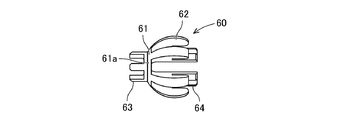
- the valve body 60 includes a valve body portion 61, a large diameter regulating portion 62, a small diameter regulating portion 63, and a mounting portion 64. As shown in FIGS. 2 to 4, the valve body 61 is formed in a plate shape or a bottomed tubular shape. In this example, the valve body 61 is formed in a plate shape.
- the outer peripheral surface of the valve body 61 includes a valve seat contact surface 61a.
- the valve seat contact surface 61a is formed in a partially spherical shape.
- the valve seat contact surface 61a can come into contact with the annular valve seat 33c1 of the third cylinder portion 33 of the connector main body 30. That is, the valve seat contact surface 61a can reciprocate between the abutting position and the separating position with respect to the annular valve seat 33c1.
- valve seat contact surface 61a In a state where the valve seat contact surface 61a is in contact with the annular valve seat 33c1, fuel is restricted from flowing in the region between the valve seat contact surface 61a and the annular valve seat 33c1. On the other hand, when the valve seat contact surface 61a is separated from the annular valve seat 33c1, the fuel can flow in the region between the valve seat contact surface 61a and the annular valve seat 33c1.
- the annular valve seat 33c1 of the third cylinder portion 33 has a tapered shape, whereas the valve seat contact surface 61a of the valve body portion 61 has a partially spherical shape. Therefore, the annular valve seat 33c1 and the valve seat contact surface 61a come into linear contact with each other. Further, even if the posture of the valve body 61 is slightly changed, the annular valve seat 33c1 and the valve seat contact surface 61a are surely in contact with each other because the valve seat contact surface 61a is partially spherical. ..
- the valve body 61 includes a tapered through hole 61b formed inward in the radial direction with respect to the valve seat contact surface 61a.
- the tapered through hole 61b forms an orifice flow path.
- the tapered through hole 61b constantly circulates fuel between the first cylinder portion 31 and the second cylinder portion 32 in the connector main body 30. Therefore, the tapered through hole 61b allows the low-pressure fuel to flow in the forward direction from the first cylinder portion 31 to the second cylinder portion 32 side, and the high-pressure fuel flows from the second cylinder portion 32 to the first cylinder portion 32. Allows distribution in the opposite direction to the 31 side.
- one tapered through hole 61b may be formed in the valve main body 61, or a plurality of tapered through holes 61b may be formed in the valve main body 61.
- the tapered through hole 61b is formed, for example, at the center of the valve body 61.
- the tapered through hole 61b is formed in a tapered shape, it has a small diameter opening and a large diameter opening.
- the small diameter opening of the tapered through hole 61b is arranged on the low pressure pump 12 side, and the large diameter opening is arranged on the high pressure pump 16 side.
- the small diameter opening may be arranged on the high pressure pump 16 side, and the large diameter opening may be arranged on the low pressure pump 12 side.
- the large diameter regulating portion 62 is integrally formed with the valve body portion 61 so as to extend from the outer peripheral edge of the surface of the valve body 61 on the second cylinder portion 32 side toward the second cylinder portion 32 side. It is formed. As shown in FIG. 3, the large diameter regulating portion 62 is formed in a plurality of claw shapes, and a gap through which fuel can flow is formed between the large diameter regulating portions 62 adjacent to each other in the circumferential direction. .. In this example, the large diameter regulating unit 62 shows 6 examples, but can be any number.
- the radial outer surface of the large diameter regulating portion 62 is formed in a partially spherical shape concentric with the valve seat contact surface 61a on the outer peripheral surface of the valve body portion 61.
- the radial outer surface of the large diameter regulating portion 62 may abut on the inner peripheral surface of the large diameter tubular portion 33b of the third tubular portion 33.
- the large diameter regulating portion 62 exerts a function of regulating the posture of the valve body 60 with respect to the third cylinder portion 33.
- the valve body 60 is arranged so as to be movable in the axial direction inside the third cylinder portion 33. Therefore, the large-diameter regulating portion 62 is arranged with a slight radial gap with respect to the large-diameter tubular portion 33b of the third tubular portion 33. Therefore, the posture of the valve body 60 can change slightly.
- the small diameter regulating portion 63 is integrally formed with the valve body portion 61, and is formed so as to extend in parallel with the first cylinder portion 31 from the surface of the valve body portion 61 on the first cylinder portion 31 side. Has been done. As shown in FIG. 3, the small diameter regulating portion 63 is formed in a plurality of claw shapes, and a gap through which fuel can flow is formed between the small diameter regulating portions 63 adjacent to each other in the circumferential direction. In this example, the small diameter regulation unit 63 shows four examples, but can be any number.
- the radial outer surface of the small diameter regulating portion 63 may come into contact with the inner peripheral surface of the small diameter tubular portion 33a of the third tubular portion 33.
- the small diameter regulating unit 63 regulates the posture of the valve body 60 with respect to the third cylinder portion 33.
- the valve body 60 is arranged so as to be movable in the axial direction inside the third cylinder portion 33. Therefore, the small diameter regulating portion 63 is arranged with a slight radial gap with respect to the small diameter tubular portion 33a of the third tubular portion 33. Therefore, also in this respect, the posture of the valve body 60 can change slightly.
- the mounting portion 64 is formed so as to extend in parallel in the axial direction from the radial inner surface of the large diameter regulating portion 62 toward the second cylinder portion 32 side. As shown in FIG. 3, the mounting portions 64 are formed in the shape of a plurality of claws, and gaps through which fuel can flow are formed between the mounting portions 64 adjacent in the circumferential direction. In this example, the number of mounting portions 64 is six, which is the same as that of the large diameter regulating portion 62, but can be any number. Further, the radial outer surface of the mounting portion 64 faces the radial inner surface of the large diameter regulating portion 62 in the radial direction via a gap.
- the urging member 70 is mounted on the radial outer surface side of the mounting portion 64, and urges the valve body 60 toward the annular valve seat 33c1.
- the urging member 70 uses a coil spring as an example, but other springs can also be applied. Since the urging member 70 maintains its posture, it is possible to reliably exert an urging force on the valve body 60 in the direction toward the annular valve seat 33c1. Further, the urging force of the urging member 70 is set to be equal to or lower than the pressure of the low-pressure fuel. Therefore, the urging member 70 is compressed when the pressure of the low pressure fuel is applied.
- the fixing bush 80 is made of metal or hard resin, and is formed in a tubular shape having through holes as shown in FIG.
- the through hole of the fixing bush 80 functions as a fuel flow path.
- the outer peripheral surface of the fixing bush 80 has an annular protrusion and an annular groove corresponding to the annular groove and the annular convex on the inner peripheral surface of the large diameter tubular portion 33b. Then, when both are engaged, the fixing bush 80 is positioned in the axial direction with respect to the third cylinder portion 33.
- the fixing bush 80 includes an annular inner protrusion 81 protruding inward in the radial direction, an end cylinder portion 82 extending from the outer peripheral side of the inner protrusion 81 to the valve body 60 side, and a valve body 60 from the inner peripheral side of the inner protrusion 81. It has an annular shaft protrusion 83 that projects to the side and partially faces the end cylinder portion 82.
- the urging member 70 is arranged between the end cylinder portion 82 and the shaft protrusion 83 in the radial direction, and is supported by the end surface of the inner protrusion 81. Therefore, the fixing bush 80 can reliably contact the valve seat contact surface 61a of the valve body 60 with the annular valve seat 33c1 by restricting the moving range of the valve body 60 and the urging member 70.
- FIG. 5 illustrates the case where the valve body 60 is in the first state
- FIG. 2 illustrates the case where the valve body 60 is in the second state.
- the first state is a steady state in which the high-pressure fuel does not flow back, and the valve seat contact surface 61a of the valve body 61 of the valve body 60 is annular with the third cylinder 33 of the connector body 30 due to the pressure of the low-pressure fuel.
- a forward flow path P (shown in FIG. 5) is formed between the valve seat contact surface 61a and the annular valve seat 33c1 at a distance from the valve seat 33c1 in the axial direction.
- the second state is a state in which the high-pressure fuel flows backward, the valve seat contact surface 61a of the valve body 60 is in contact with the annular valve seat 33c1, and the valve seat contact surface 61a and the annular valve are in contact with each other. The forward flow path P between the seat 33c1 and the seat 33c1 is blocked.
- the valve body 60 is in the first state.
- the low-pressure fuel regulated to a constant pressure by the low-pressure pump 12 and the pressure regulator 13 is high-pressure via the first low-pressure pipe 14, the connector 15, and the second low-pressure pipe 16a. It is supplied to the pump body 16b of the pump 16.
- the flow direction of the low-pressure fuel is the direction from the first cylinder portion 31 to the second cylinder portion 32 of the connector main body 30 (from left to right in FIG. 5). Therefore, the force received by the valve body 60 from the low-pressure fuel tends to oppose the urging force of the urging member 70.
- the urging force of the urging member 70 is set to be equal to or lower than the pressure of the pressure-adjusted low-pressure fuel. Therefore, when the pressure of the low-pressure fuel acts on the valve body 60, the urging member 70 is compressed and the valve body 60 moves to the high-pressure pump 16 side. Then, as shown in FIG. 5, the valve seat contact surface 61a of the valve body 61 of the valve body 60 is in the first state separated from the annular valve seat 33c1 of the third cylinder 33 of the connector body 30.
- a forward flow path P is formed between the annular valve seat 33c1 and the valve seat contact surface 61a.
- the forward flow path P is formed on the entire circumference of the valve seat contact surface 61a in the circumferential direction. Further, since the cross section of the forward flow path P is set sufficiently large, there is almost no decrease in the pressure of the low pressure fuel in the forward flow path P. Therefore, the low-pressure fuel is supplied to the pump body 16b of the high-pressure pump 16 while maintaining a desired pressure state.
- the tapered through hole 61b always allows the flow of fuel. Therefore, the low-pressure fuel flows through the tapered through hole 61b in addition to the forward flow path P.
- the cross-sectional area of the flow path in the small-diameter opening of the tapered through hole 61b is much smaller than the cross-section of the flow path of the forward flow path P. Therefore, most of the low pressure fuel flows through the forward flow path P.
- the valve body 60 is in the second state.
- the case of the second state will be described with reference to FIG.
- the high-pressure fuel flows backward, the high-pressure fuel is present in the second low-pressure pipe 16a.
- low pressure fuel is present in the first low pressure pipe 14.
- the fuel acting on both sides of the valve body 60 has a pressure difference. Then, the high-pressure fuel tries to flow from the second low-pressure pipe 16a to the first low-pressure pipe 14 side.
- valve body 60 moves to the low pressure pump 12 side due to the pressure of the high pressure fuel. As a result, the valve body 60 is pressed against the annular valve seat 33c1 side. Therefore, the valve seat contact surface 61a of the valve body 61 of the valve body 60 is in a second state of contacting the annular valve seat 33c1. Therefore, the flow of fuel is restricted between the valve seat contact surface 61a and the annular valve seat 33c1.
- the valve body 61 is always formed with a tapered through hole 61b that allows the flow of fuel. That is, between the high pressure pump 16 side and the low pressure pump 12 side, the high pressure fuel slightly flows to the low pressure pump 12 side through the tapered through hole 61b. In this way, the backflow of high pressure fuel is allowed only by the tapered through hole 61b.
- the tapered through hole 61b forms an orifice flow path having a flow path cross section smaller than that of the forward flow path P. Therefore, the high-pressure fuel in the second low-pressure pipe 16a flows to the first low-pressure pipe 14 through the tapered through hole 61b as the orifice flow path. Therefore, it is possible to prevent the pressure fluctuation of the high-pressure fuel generated in the pump body 16b of the high-pressure pump 16 from being directly transmitted to the first low-pressure pipe 14 due to the orifice flow path action of the tapered through hole 61b. That is, the pulsation in the first low pressure pipe 14 can be reduced.
- valve body 60 is built in the connector 15. Therefore, the valve body 60 can be easily arranged.
- the inner peripheral surface of the third cylinder portion 33 of the connector main body 30 is a surface forming the forward flow path P. Since the connector body 30 is easily formed, it is also easy to form the forward flow path P on the inner peripheral surface of the connector body 30. Therefore, the design and manufacture of the connector 15 incorporating the valve body 60 becomes easy.
- valve body 60 is arranged in the first low pressure pipe 14 instead of being built in the connector 15.
- arranging the valve body 60 in the first low-pressure pipe 14 is not as easy as arranging the valve body 60 in the connector main body 30. Therefore, arranging the valve body 60 in the first low-pressure pipe 14 is not easy to design and manufacture, and leads to high cost. Therefore, by arranging the valve body 60 inside the connector main body 30, it is possible to easily design and manufacture the valve body 60, and it is possible to surely exert the pulsation reducing effect.
- valve seat contact surface 61a of the valve body 61 has a partially spherical shape.
- the valve seat contact surface 61a surely contacts the annular valve seat 33c1. That is, in the second state, the annular valve seat 33c1 and the valve seat contact surface 61a can reliably regulate the flow of high-pressure fluid.
- the tapered through hole 61b can surely exert the orifice flow path action, and as a result, the pulsation reduction effect can be surely exerted.
- the tapered through hole 61b has a small diameter opening located on the low pressure pump 12 side and a large diameter opening located on the high pressure pump 16 side.
- the fuel flow resistance is small in the direction from the large diameter opening to the small diameter opening and large in the opposite direction. It is advisable to position the small-diameter opening on the inlet side where the flow resistance is to be increased.
- the small diameter opening is located on the low pressure pump 12 side, the flow resistance from the low pressure pump 12 side to the high pressure pump 16 side is large. Therefore, in the first state in which the low-pressure fuel flows in the forward direction, the fuel flowing through the tapered through hole 61b is much smaller than the forward flow path P.
- the tapered shape of the tapered through-hole 61b acts to guide the high-pressure fuel into the tapered through-hole 61b. That is, the high-pressure fuel can be guided to the small-diameter opening having the minimum flow path cross section. As a result, the tapered through hole 61b as the orifice flow path can function more effectively.
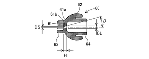
- the inner diameter DS of the small diameter opening of the tapered through hole 61b is 0.1 mm to 2.0 mm, preferably 0.1 mm to 1.0 mm.
- This small diameter opening greatly affects the function as an orifice flow path. Therefore, the inner diameter of the small-diameter opening is set according to the degree of function as an orifice flow path.
- the inner diameter DL of the large diameter opening of the tapered through hole 61b is 1.0 mm or more, preferably 2.0 mm or more, and more preferably 3.0 mm or more.
- the large-diameter opening exerts a function of guiding high-pressure fuel into the tapered through hole 61b. Therefore, the inner diameter DL of the large diameter opening is set according to the degree of the induction function of the high pressure fuel, and is set according to the inner diameter DS of the small diameter opening.
- the taper angle ⁇ of the tapered through hole 61b is 5 ° to 45 °, preferably 10 ° to 30 °.
- the taper angle ⁇ corresponds to the apex angle of the cone of the tapered through hole 61b. If the taper angle ⁇ is smaller than 5 °, it causes a decrease in the life of the mold 120 (shown in FIG. 6) described later. When the taper angle ⁇ is larger than 45 °, the durability of the valve main body 61 is lowered due to the presence of a thin portion of the valve main body 61.
- the axial distance H between the small diameter opening and the large diameter opening is 1.0 mm to 4.0 mm. If the axial distance H is smaller than 1.0 mm, it causes a decrease in the durability of the valve body 61. If the axial distance H is larger than 4.0 mm, it causes a decrease in the life of the mold 120, which will be described later.
- the molds 110 and 120 for molding the valve body 60 will be described with reference to FIG.
- the valve body 60 is formed by the first mold 110 and the second mold 120. That is, the valve body 60 is formed by supplying a molten material, for example, a molten resin, to the cavities of the molds 110 and 120.
- the first mold 110 has a first cavity surface 111 corresponding to the small diameter regulating portion 63 side
- the second mold 120 has a second cavity surface 121 corresponding to the mounting portion 64 side.
- the second mold 120 has a protrusion 122 on which the tapered through hole 61b is transferred.
- the base end of the protrusion 122 corresponds to the large diameter opening of the tapered through hole 61b
- the tip of the protrusion 122 corresponds to the small diameter opening of the tapered through hole 61b.
- the first mold 110 has a recess 112 for positioning the protrusion 122 by inserting the tip of the protrusion 122 of the second mold 120.
- the second mold 120 is provided with the protrusion 122.
- the protrusion 122 of the second mold 120 also has a small diameter, and the durability of the protrusion 122 of the second mold 120 becomes an issue.
- the tapered through hole 61b as the orifice flow path is formed in a tapered shape. Therefore, the protrusion 122 of the second mold 120 for forming the tapered through hole 61b is also tapered.
- the second mold 120 can be designed so that the large-diameter side of the tapered protrusion 122 is the base end side and the small-diameter side of the tapered protrusion 122 is the tip side.
- the rigidity of the protrusions 122 is increased by making the protrusions 122 tapered.
- the protrusion 122 has rigidity, so that the durability of the protrusion 122 is improved. That is, by making the tapered through hole 61b of the valve body 60 tapered, the life of the second mold 120 can be extended.
- the inner diameter of the small diameter opening can be made very small.
- the inner diameter DS of the small diameter opening can be 0.1 mm to 2.0 mm, preferably 0.1 mm to 1.0 mm.
- the tip of the protrusion 122 is supported in a state of being inserted into the recess 112 of the first mold 110. Therefore, even if the pressure of the molten material acts on the tip portion of the protrusion 122 having a small diameter, the durability of the protrusion 122 can be improved by being supported by the recess 112.
Landscapes
- Engineering & Computer Science (AREA)
- General Engineering & Computer Science (AREA)
- Mechanical Engineering (AREA)
- Chemical & Material Sciences (AREA)
- Combustion & Propulsion (AREA)
- Fuel-Injection Apparatus (AREA)
Abstract
高圧燃料を供給可能な燃料供給系において、簡易な構造により低圧配管における脈動を低減することができると共に、金型の長寿命化を図ることができるコネクタ(15)の弁体(60)は、高圧燃料が逆流しない場合には低圧燃料の圧力によって環状弁座(33c1)から軸方向に離間して順方向流路(P)を形成し、高圧燃料が逆流する場合には環状弁座(33c1)に当接可能な弁座当接面(61a)と、弁座当接面(61a)よりも径方向内方に形成され、順方向流路(P)よりも流路断面積が小さなオリフィス流路を形成し、高圧燃料が逆流する場合に高圧燃料の逆流を許容するテーパ状貫通孔(61b)とを備える。
Description
本発明は、コネクタに関するものである。
特開2007-218264号公報及び特開2000-265926号公報に記載されているように、燃料タンクから低圧ポンプにより供給された低圧燃料を高圧ポンプにより加圧し、加圧された高圧燃料を内燃機関に供給する燃料供給系が存在する。当該燃料供給系において、高圧ポンプの駆動に起因して、低圧燃料が流通する低圧配管にて脈動が発生するため、当該脈動を低減することが求められる。特に、高圧ポンプにより加圧された高圧燃料が低圧配管側へ逆流する場合に、低圧配管における脈動が問題となる。
特開2007-218264号公報においては、低圧配管における脈動を低減するために、ダンパ機構が設けられている。特開2000-265926号公報においては、低圧配管における脈動を低減するために、高圧ポンプから低圧配管側に燃料の一部を戻す戻し通路が設けられ、当該戻し通路を開放するための電磁弁とオリフィスとが設けられている。
しかし、ダンパ機構や戻し通路を設けることは、構造が複雑化すると共に、高コスト化を招来する。さらに、製造コストの低減を図ることも必要である。例えば、ダイキャストや射出成形などの溶融材料を金型内に供給する製法によって弁体を成形する際には、金型の長寿命化を図ることが求められる。従って、金型の長寿命化が可能となるように、弁体の形状を設計する必要がある。
本発明は、高圧燃料を供給可能な燃料供給系において、簡易な構造により低圧配管における脈動を低減することができると共に、金型の長寿命化を図ることができるコネクタを提供することを目的とする。
本発明に係るコネクタは、低圧ポンプから供給される低圧燃料を高圧ポンプにより加圧して内燃機関へ高圧燃料を供給する燃料供給系において、前記低圧燃料が流通する低圧配管に接続されるコネクタである。コネクタは、筒状に形成され、内周面に環状弁座を有するコネクタ本体と、前記コネクタ本体の内部に収容され、前記コネクタ本体の流路方向に往復移動可能に配置された弁体とを備える。
前記弁体は、外周面に形成され、前記高圧燃料が逆流しない場合には前記低圧燃料の圧力によって前記コネクタ本体の前記環状弁座から軸方向に離間して前記コネクタ本体の前記環状弁座との間に順方向流路を形成し、前記高圧燃料が逆流する場合には前記コネクタ本体の前記環状弁座に当接可能な弁座当接面と、前記弁座当接面よりも径方向内方に形成され、前記順方向流路よりも流路断面積が小さなオリフィス流路を形成し、前記高圧燃料が逆流する場合に前記高圧燃料の逆流を許容するテーパ状貫通孔とを備える。
高圧燃料が逆流しない定常状態においては、低圧燃料の圧力によって弁体が高圧ポンプ側に移動する。その結果、弁体の弁座当接面がコネクタ本体の環状弁座から離間した状態となる。そして、コネクタ本体の環状弁座と弁座当接面との間に、順方向流路が形成される。従って、低圧燃料は、順方向流路を流通することによって、高圧ポンプ側に供給される。
一方、高圧燃料が逆流する場合には、高圧燃料の圧力によって弁体が低圧ポンプ側に移動する。その結果、弁体の弁座当接面がコネクタ本体の環状弁座に当接した状態となる。ただし、弁体には、オリフィス流路を形成するためのテーパ状貫通孔が形成されている。従って、高圧燃料が、テーパ状貫通孔を介して低圧ポンプ側に僅かに流通する。テーパ状貫通孔によるオリフィス流路作用によって、コネクタよりも低圧ポンプ側の低圧配管における脈動が低減する。
また、弁体は、コネクタに内蔵される構成としている。ここで、弁体をコネクタに内蔵されるのではなく、低圧配管に配置することが考えられる。しかしながら、低圧配管に弁体を配置することは、コネクタ本体に弁体を配置することに比べて容易ではない。そのため、低圧配管に弁体を配置することは、設計および製造が容易ではなく、高コスト化を招来する。従って、弁体が、コネクタ本体の内部に配置されることによって、容易に設計および製造が可能となり、確実に脈動低減効果を発揮することができる。
また、オリフィス流路としてのテーパ状貫通孔は、弁体に形成されている。弁体に貫通孔を形成するためには、金型に貫通孔を転写した突起部を設けることが必要となる。しかしながら、貫通孔が小径である場合には、金型の突起部も小径となり、金型の突起部の耐久性が課題となる。
そこで、オリフィス流路としての貫通孔をテーパ状とした。テーパ状貫通孔を形成するための金型の突起部も、テーパ状となる。従って、金型は、テーパ状突起部の大径側を基端側とし、テーパ状突起部の小径側を先端側とするように設計することができる。金型の突起部が全長に亘って同一径に形成される場合に比べて、突起部をテーパ状とすることで、突起部の耐久性が向上する。つまり、弁体の貫通孔をテーパ状とすることによって、金型の長寿命化を図ることができる。
(1.燃料供給系1の構成)
燃料供給系1の構成について、図1を参照して説明する。図1に示すように、燃料供給系1は、燃料タンク11から内燃機関20へ供給する系である。特に、燃料供給系1においては、低圧ポンプ12から供給される低圧燃料が高圧ポンプ16により加圧され、加圧された高圧燃料が内燃機関20へ供給される。燃料供給系1は、燃料タンク11、低圧ポンプ12、プレッシャレギュレータ13、第一低圧配管14、コネクタ15、高圧ポンプ16、高圧配管17、コモンレール18、インジェクタ19、内燃機関20を備える。
燃料供給系1の構成について、図1を参照して説明する。図1に示すように、燃料供給系1は、燃料タンク11から内燃機関20へ供給する系である。特に、燃料供給系1においては、低圧ポンプ12から供給される低圧燃料が高圧ポンプ16により加圧され、加圧された高圧燃料が内燃機関20へ供給される。燃料供給系1は、燃料タンク11、低圧ポンプ12、プレッシャレギュレータ13、第一低圧配管14、コネクタ15、高圧ポンプ16、高圧配管17、コモンレール18、インジェクタ19、内燃機関20を備える。
低圧ポンプ12は、燃料タンク11の内部に配置され、低圧ポンプ12の吐出側には、例えば樹脂製の第一低圧配管14の第一端が接続されている。つまり、低圧ポンプ12は、燃料タンク11に貯留されている燃料を第一低圧配管14側に圧送する。プレッシャレギュレータ13は、燃料タンク11内において、第一低圧配管14における低圧ポンプ12側に配置されている。プレッシャレギュレータ13によって、第一低圧配管14を流通する低圧燃料が一定の圧力に調圧される。
第一低圧配管14の第二端(低圧ポンプ12とは反対側)は、コネクタ15の第一端(後述する第一筒部31)に接続されている。コネクタ15の第二端(後述する第二筒部32)は、高圧ポンプ16に一体に設けられている第二低圧配管16aに接続されている。つまり、コネクタ15は、低圧燃料が流通する2つの低圧配管(第一低圧配管14および第二低圧配管16a)を連結する。詳細には、コネクタ15は、第一低圧配管14と第二低圧配管16aとを接続すると共に、第一低圧配管14および第二低圧配管16aと共に低圧燃料を供給する流路を構成する。
高圧ポンプ16は、低圧ポンプ12およびプレッシャレギュレータ13から供給される一定圧の低圧燃料を、第一低圧配管14、コネクタ15および第二低圧配管16aを介して導入する。高圧ポンプ16は、導入した低圧燃料を加圧し、加圧した高圧燃料を吐出する。
高圧ポンプ16は、例えば、上述した第二低圧配管16aと、第二低圧配管16aに接続されたポンプ本体16bと、ポンプ本体16b内に往復移動可能に設けられたプランジャ16cとを備える。従って、ポンプ本体16bに導入された低圧燃料が、プランジャ16cの往復動によって加圧される。ただし、高圧ポンプ16は、プランジャ16cに限られず、燃料を加圧することができれば、種々の構成を採用できる。
また、高圧ポンプ16は、例えば、内燃機関20の動作に連動する機構である場合がある。この場合、内燃機関20が動作している最中は、高圧ポンプ16は、高圧燃料を吐出するか否かに関わりなく動作し続けることになる。例えば、高圧ポンプ16がプランジャ16cを有する構成である場合において、プランジャ16cが、内燃機関20を構成するクランクシャフトと連動するカムによって往復動する構成が存在する。この場合、プランジャ16cは、クランクシャフトが動作している間、継続して往復動することになる。
高圧ポンプ16によって加圧された高圧燃料は、高圧配管17を介してコモンレール18に供給される。コモンレール18には、内燃機関20の気筒数に対応するインジェクタ19が設けられており、インジェクタ19は、内燃機関20に装着されている。従って、高圧燃料は、コモンレール18およびインジェクタ19を介して内燃機関20に噴射される。
(2.燃料供給系1の動作)
燃料供給系1の動作について、図1を参照して説明する。内燃機関20に高圧燃料の供給が必要な場合には、低圧ポンプ12および高圧ポンプ16が動作する。すなわち、低圧ポンプ12が動作して第一低圧配管14、コネクタ15および第二低圧配管16aには低圧燃料が順方向(低圧ポンプ12から高圧ポンプ16に向かう方向)に流通し、当該低圧燃料が高圧ポンプ16にて加圧される。そして、高圧ポンプ16で加圧された高圧燃料が、高圧配管17、コモンレール18およびインジェクタ19を介して、内燃機関20に供給される。
燃料供給系1の動作について、図1を参照して説明する。内燃機関20に高圧燃料の供給が必要な場合には、低圧ポンプ12および高圧ポンプ16が動作する。すなわち、低圧ポンプ12が動作して第一低圧配管14、コネクタ15および第二低圧配管16aには低圧燃料が順方向(低圧ポンプ12から高圧ポンプ16に向かう方向)に流通し、当該低圧燃料が高圧ポンプ16にて加圧される。そして、高圧ポンプ16で加圧された高圧燃料が、高圧配管17、コモンレール18およびインジェクタ19を介して、内燃機関20に供給される。
一方、内燃機関20の動作中において、内燃機関20に高圧燃料の供給が不要の場合がある。この場合には、インジェクタ19から内燃機関20に高圧燃料が供給されないようにされている。しかし、内燃機関20が動作中であるため、内燃機関20を構成するクランクシャフトは動作し続けている。
そして、高圧ポンプ16のプランジャ16cは、内燃機関20を構成するクランクシャフトと連動するカムによって動作する。そのため、内燃機関20に高圧燃料の供給が不要の場合であっても、クランクシャフトが動作している間は、高圧ポンプ16のプランジャ16cも動作し続ける。
このとき、低圧ポンプ12が動作し続けていると、低圧燃料が第一低圧配管14、コネクタ15および第二低圧配管16aを介して高圧ポンプ16に供給され続ける。高圧ポンプ16では、低圧燃料を加圧するが、加圧した高圧燃料を内燃機関20側へ供給することはできない。そのため、高圧ポンプ16によって加圧された高圧燃料が第二低圧配管16a、コネクタ15および第一低圧配管14へ逆流する現象が、発生することがある。
高圧燃料の逆流によって、第一低圧配管14に脈動が発生することがある。第一低圧配管14における脈動に起因して第一低圧配管14が振動すると、異音等が発生するおそれがある。ただし、以下に説明するように、コネクタ15は、第一低圧配管14における脈動を低減する機能を有する。そのため、第一低圧配管14における脈動が低減し、異音等の発生が抑制される。
(3.コネクタ15の構成)
コネクタ15の構成について、図2および図3を参照して説明する。コネクタ15は、図2に示すように、第一低圧配管14と第二低圧配管16aとを接続し、第一低圧配管14と第二低圧配管16aとの間で燃料を流通させる。コネクタ15の第一端側には、第一低圧配管14の端部が外挿され、コネクタ15の第二端側には、第二低圧配管16aの端部が挿入される。
コネクタ15の構成について、図2および図3を参照して説明する。コネクタ15は、図2に示すように、第一低圧配管14と第二低圧配管16aとを接続し、第一低圧配管14と第二低圧配管16aとの間で燃料を流通させる。コネクタ15の第一端側には、第一低圧配管14の端部が外挿され、コネクタ15の第二端側には、第二低圧配管16aの端部が挿入される。
ここで、第一低圧配管14は、例えば樹脂により形成され、且つ、薄肉筒状に形成されている。従って、第一低圧配管14は、コネクタ15に比べて拡径変形可能に形成されている。また、第二低圧配管16aは、例えば金属または硬質樹脂により形成され、且つ、筒状に形成されている。第二低圧配管16aの端部は、先端から軸方向に距離を隔てた位置に径方向外方に突出形成された環状フランジ16a1(ビードとも称する)と、環状フランジ16a1より先端側の小径部位である先端部16a2とを備える。
コネクタ15は、以下において、クイックコネクタタイプを例に挙げて説明するが、クイックコネクタタイプに限られず、配管同士を連結することができればよい。また、コネクタ15は、クイックコネクタタイプにおいて、以下に例示する構成に限られず、種々のクイックコネクタタイプを適用することが可能である。
コネクタ15は、例えば、コネクタ本体30と、リテーナ40と、シールユニット50と、弁体60、付勢部材70、固定用ブッシュ80とを備える。コネクタ本体30は、両端に第一開口31aおよび第二開口32aを有する筒状に形成されている。そして、コネクタ本体30は、第一低圧配管14に接続される第一開口31aと第二低圧配管16aに接続される第二開口32aとの間で、燃料を流通させる。換言すると、コネクタ本体30は、第一開口31aと第二開口32aとの間で燃料を流通するための部材である。
本例においては、コネクタ本体30は、直線状の筒状に形成されている。ただし、コネクタ本体30は、直線状に限られることなく、L字筒状等のように、屈曲部(図示せず)を有する筒状に形成されるようにしてもよい。また、コネクタ本体30は、硬質樹脂により一体成形されており、一つの部材により構成されている。例えば、コネクタ本体30は、射出成形により一体成形されている。コネクタ本体30は、例えばガラス繊維強化ポリアミド製である。なお、コネクタ本体30は、複数の部材を一体化させることにより形成するようにしてもよい。
コネクタ本体30は、流路方向に区分した場合、第一筒部31、第二筒部32、および、第三筒部33を備える。流体の順方向において、第一筒部31、第三筒部33、第二筒部32の順に接続されている。
第一筒部31は、第一低圧配管14に接続される部位である。第一筒部31は、第一開口31aを備える部分であって、直線筒状に形成されている。第一開口31aは、第一低圧配管14の端部が外装される側の開口である。第一筒部31は、第一低圧配管14の端部を第一筒部31の第一開口31a側の外周側に嵌装した状態において、流路方向において第一低圧配管14と重なる範囲である。つまり、第一筒部31の外周面は、全長において、第一低圧配管14の内周面と径方向において対向する。
第一筒部31の内周面は、例えば円筒状に形成されている。そして、第一筒部31の内周面は、燃料が直接接触する面を構成する。一方、第一筒部31の外周面は、第一低圧配管14を外装した状態で抜けないようにするために、流路方向断面において凹凸状に形成されている。なお、第一筒部31の外周面に環状シール部材を配置して、第一筒部31の外周面と第一低圧配管14の内周面との間でシール性能を有するようにされている。
ここで、第一筒部31は、第一低圧配管14より変形しにくい材料により形成されている。従って、第一筒部31に第一低圧配管14が外装された状態において、第一筒部31は、ほとんど変形せず、第一低圧配管14が拡径する。つまり、第一低圧配管14が、第一筒部31の外周面の凹凸に倣って変形する。
第二筒部32は、第二低圧配管16aに接続される部位であると共に、リテーナ40およびシールユニット50が配置される部位である。第二筒部32は、第二開口32aを備える部分であって、直線筒状に形成されている。第二開口32aは、第二低圧配管16aの先端部16a2および環状フランジ16a1が挿入される側の開口である。第二筒部32は、第二低圧配管16aが挿入された状態において、流路方向において第二低圧配管16aと重なる範囲である。
第二筒部32は、第二開口32a側にリテーナ配置部32bを備える。リテーナ配置部32bは、径方向に貫通する孔を有し、リテーナ40を配置する部位である。リテーナ40に対して、径方向に係止可能に構成されている。リテーナ配置部32bは、リテーナ40の構造に応じて適宜異なる形状に形成される。本例では、コネクタ本体30とリテーナ40とが別体に形成されているが、リテーナ40の機能がコネクタ本体30に一体的に設けられる構成とすることもできる。
第二筒部32は、リテーナ配置部32bを基準として第二開口32aとは反対側に、シール部32cを備える。シール部32cの内周面は、例えば、円筒状に形成されている。シール部32cの内周側には、シールユニット50が配置される。ここで、第二筒部32の内周面の直径は、第一筒部31の内周面の直径より大きい。例えば、第一筒部31の内周面の直径と第二低圧配管16aの内周面の直径とが同等となるように、第二筒部32の内周面の直径は、第二低圧配管16aの厚みおよびシールユニット50の厚みを考慮して決定されている。
第三筒部33は、弁体60、付勢部材70および固定用ブッシュ80が配置される部位である。第三筒部33は、第一筒部31における第一開口31aとは反対側と、第二筒部32における第二開口32aとは反対側とを、流路方向において接続する。第三筒部33は、第一低圧配管14も第二低圧配管16aも存在しない範囲である。
また、第三筒部33は、小径筒部33aと大径筒部33bと拡径部33cとを備える。小径筒部33aは、第一筒部31と同軸に接続される。従って、小径筒部33aは、第三筒部33において第一開口31a側に位置する。小径筒部33aの内周面の直径は、第一筒部31の内周面の直径と同等である。従って、小径筒部33aは、第三筒部33において小径流路を形成する。
大径筒部33bは、第二筒部32と同軸に接続される。従って、大径筒部33bは、第三筒部33において第二開口32a側に位置する。大径筒部33bの内周面の直径は、第二筒部32における第二低圧配管16aの最先端(先端部16a2の開口を有する部分)が内挿される部位の内周面の直径とほぼ同等である。大径筒部33bは、第三筒部33において大径流路を形成する。また、本例においては、大径筒部33bと小径筒部33aとは、同軸状に位置する。また、大径筒部33bの内周面は、軸方向の中央付近または第二筒部32側において、環状溝および環状凸部を有する。
拡径部33cは、小径筒部33aと大径筒部33bとを接続する。拡径部33cは、内周面に環状弁座33c1を有する。環状弁座33c1は、小径筒部33aの内周面と大径筒部33bの内周面とを接続するテーパ状に形成されている。環状弁座33c1は、小径筒部33aの内周面から大径筒部33bの内周面に向かって拡径している。環状弁座33c1は、弁体60に当接する部位である。
リテーナ40は、例えばガラス繊維強化ポリアミド製である。リテーナ40は、コネクタ本体30のリテーナ配置部32bに保持される。リテーナ40は、コネクタ本体30と第二低圧配管16aとを連結するための部材である。なお、リテーナ40は、以下に説明する構成に限られず、種々の公知の構成を採用できる。
リテーナ40は、作業者による押し込み操作および引き抜き操作によって、リテーナ配置部32bの径方向に移動可能である。第二低圧配管16aが第二筒部32の正規位置に挿入された場合に、リテーナ40が図2に示す初期位置(図2に示す位置)から確認位置(図2の下方へ向かう位置、図5に示す位置)へ移動可能となる。従って、作業者は、リテーナ40が押し込み操作できる場合には、第二低圧配管16aが第二筒部32の正規位置に挿入されたことを確認できる。
さらに、リテーナ40が確認位置へ押し込み操作された状態において、リテーナ40は、第二低圧配管16aの環状フランジ16a1に配管引き抜き方向に係止して、リテーナ40は第二低圧配管16aを抜け止めする。つまり、作業者は、リテーナ40を押し込み操作することによって、第二低圧配管16aが第二筒部32の正規位置に挿入され、且つ、第二低圧配管16aがリテーナ40によって抜止されていることを、確認することができる。
シールユニット50は、コネクタ本体30の第二筒部32の内周面と第二低圧配管16aの外周面との間における燃料の流通を規制する。シールユニット50は、例えば、フッ素ゴム製の環状シール部材51,52と、環状シール部材51,52の軸方向の間に挟まれるようにして樹脂製のカラー53と、環状シール部材51,52およびカラー53を第二筒部32のシール部32cに位置決めする樹脂製のブッシュ54とから構成される。シールユニット50の内周側には、第二低圧配管16aの先端部16a2が挿入され、第二低圧配管16aの環状フランジ16a1は、シールユニット50より第二開口32a側に位置する。
弁体60は、高圧燃料が逆流しない定常状態の場合には低圧燃料を順方向に流通し、高圧燃料が逆流する場合には脈動を低減するように機能する。弁体60は、コネクタ本体30の第三筒部33の内部に収容されており、第三筒部33の軸方向に往復移動可能である。つまり、弁体60は、第三筒部33において、流路方向に往復移動可能である。弁体60は、金属または硬質樹脂により一体に形成されている。
弁体60は、弁本体部61と、大径規制部62と、小径規制部63と、装着部64とを備える。弁本体部61は、図2-図4に示すように、板状または有底筒状に形成されている。本例においては、弁本体部61は、板状に形成されている。
弁本体部61の外周面は、図3および図4に示すように、弁座当接面61aを備える。弁座当接面61aは、部分球面状に形成されている。弁座当接面61aは、コネクタ本体30の第三筒部33の環状弁座33c1に当接可能である。つまり、弁座当接面61aは、環状弁座33c1に対して、当接する位置と離間する位置との間で往復移動可能である。
弁座当接面61aが環状弁座33c1に当接する状態においては、燃料は、弁座当接面61aと環状弁座33c1との間の領域を流通することが規制される。一方、弁座当接面61aが環状弁座33c1から離間する状態においては、燃料は、弁座当接面61aと環状弁座33c1との間の領域を流通可能となる。
ここで、第三筒部33の環状弁座33c1は、テーパ状であるのに対して、弁本体部61の弁座当接面61aは、部分球面状である。そのため、環状弁座33c1と弁座当接面61aとは、線状に接触する。さらに、仮に、弁本体部61の姿勢が僅かに変化したとしても、弁座当接面61aが部分球面状であることから、環状弁座33c1と弁座当接面61aとは確実に当接する。
弁本体部61は、弁座当接面61aよりも径方向内方に形成されたテーパ状貫通孔61bを備える。テーパ状貫通孔61bは、オリフィス流路を形成する。そして、テーパ状貫通孔61bは、コネクタ本体30において、第一筒部31と第二筒部32との間における燃料の流通を常時流通する。従って、テーパ状貫通孔61bは、低圧燃料が第一筒部31から第二筒部32側への順方向に流通することを許容すると共に、高圧燃料が第二筒部32から第一筒部31側への逆方向に流通することを許容する。
さらに、テーパ状貫通孔61bは、弁本体部61に1つ形成されるようにしてもよいし、弁本体部61に複数形成されるようにしてもよい。テーパ状貫通孔61bが1つ形成される場合には、テーパ状貫通孔61bは、例えば、弁本体部61の中心に形成される。また、テーパ状貫通孔61bは、テーパ状に形成されているため、小径開口と大径開口とを有する。本例では、テーパ状貫通孔61bの小径開口は、低圧ポンプ12側に配置されており、大径開口は、高圧ポンプ16側に配置されている。ただし、小径開口が高圧ポンプ16側に配置され、大径開口が低圧ポンプ12側に配置されるようにしてもよい。
大径規制部62は、弁本体部61に一体に形成されており、弁本体部61における第二筒部32側の面のうち外周縁から、第二筒部32側に向かって延びるように形成されている。図3に示すように、大径規制部62は、複数の爪状に形成されており、周方向に隣接する大径規制部62の間には、燃料が流通可能な隙間が形成されている。本例においては、大径規制部62は、6個の例を示すが、任意の数とすることができる。
大径規制部62の径方向外面は、弁本体部61の外周面の弁座当接面61aと同心の部分球面状に形成されている。大径規制部62の径方向外面は、第三筒部33の大径筒部33bの内周面に当接し得る。これにより、大径規制部62は、第三筒部33に対して弁体60の姿勢を規制する機能を発揮する。ただし、弁体60は第三筒部33の内部において軸方向に移動可能に配置されている。そのため、大径規制部62は、第三筒部33の大径筒部33bに対して僅かに径方向隙間を有して配置されている。従って、弁体60の姿勢は、僅かではあるが変化し得る。
小径規制部63は、弁本体部61に一体に形成されており、弁本体部61における第一筒部31側の面から、第一筒部31に向かって軸方向に平行に延びるように形成されている。図3に示すように、小径規制部63は、複数の爪状に形成されており、周方向に隣接する小径規制部63の間には、燃料が流通可能な隙間が形成されている。本例においては、小径規制部63は、4個の例を示すが、任意の数とすることができる。
小径規制部63の径方向外面は、第三筒部33の小径筒部33aの内周面に当接し得る。これにより、小径規制部63は、第三筒部33に対して弁体60の姿勢を規制する。ただし、弁体60は第三筒部33の内部において軸方向に移動可能に配置されている。そのため、小径規制部63は、第三筒部33の小径筒部33aに対して僅かに径方向隙間を有して配置されている。従って、この点においても、弁体60の姿勢は、僅かではあるが変化し得る。
装着部64は、大径規制部62の径方向内面から第二筒部32側に向かって軸方向に平行に延びるように形成されている。図3に示すように、装着部64は、複数の爪状に形成されており、周方向に隣接する装着部64の間には、燃料が流通可能な隙間が形成されている。本例においては、装着部64は、大径規制部62と同数の6個の例を示すが、任意の数とすることができる。さらに、装着部64の径方向外面は、大径規制部62の径方向内面に対して径方向に隙間を介して対向している。
付勢部材70は、装着部64の径方向外面側に装着され、弁体60を環状弁座33c1に向かって付勢する。付勢部材70は、コイルスプリングを例にあげるが、その他のスプリングを適用することもできる。付勢部材70は、姿勢が維持されているため、弁体60に対して環状弁座33c1に向かう方向への付勢力を確実に作用させることができる。また、付勢部材70の付勢力は、低圧燃料の圧力以下に設定されている。従って、付勢部材70は、低圧燃料の圧力が作用した場合には圧縮される。
固定用ブッシュ80は、金属または硬質樹脂により形成されており、図2に示すように、貫通孔を有する筒状に形成されている。固定用ブッシュ80の貫通孔が燃料の流路として機能する。固定用ブッシュ80の外周面には、大径筒部33bの内周面における環状溝および環状凸部に対応する、環状凸部および環状溝を有する。そして、両者が係合することにより、固定用ブッシュ80は、第三筒部33に対して軸方向に位置決めされている。
さらに、固定用ブッシュ80は、径方向内方に突出する環状の内突起81、内突起81の外周側から弁体60側に延びる端筒部82、内突起81の内周側から弁体60側に突出し端筒部82に部分的に対向する環状の軸突起83を有する。付勢部材70が、端筒部82と軸突起83との径方向間に配置されており、内突起81の端面により支持されている。従って、固定用ブッシュ80は、弁体60および付勢部材70の移動範囲を規制することにより、弁体60の弁座当接面61aを環状弁座33c1に確実に当接可能としている。
(4.弁体60の作用)
弁体60の作用について、図2および図5を参照して説明する。ここで、図5は、弁体60が第一状態である場合を図示し、図2は、弁体60が第二状態である場合を図示する。
弁体60の作用について、図2および図5を参照して説明する。ここで、図5は、弁体60が第一状態である場合を図示し、図2は、弁体60が第二状態である場合を図示する。
第一状態とは、高圧燃料が逆流しない定常状態の場合に、弁体60の弁本体部61の弁座当接面61aが、低圧燃料の圧力によってコネクタ本体30の第三筒部33の環状弁座33c1から軸方向に離間して、弁座当接面61aと環状弁座33c1との間に順方向流路P(図5に示す)が形成される状態である。第二状態とは、高圧燃料が逆流する状態であって、弁体60の弁座当接面61aが環状弁座33c1に当接している状態であって、弁座当接面61aと環状弁座33c1との間における順方向流路Pが閉塞された状態である。
まず、高圧燃料が逆流しない定常状態の場合には、弁体60は第一状態となる。第一状態の場合について、図5を参照して説明する。高圧燃料が逆流しない定常状態の場合には、低圧ポンプ12およびプレッシャレギュレータ13により一定圧に調圧された低圧燃料が、第一低圧配管14、コネクタ15および第二低圧配管16aを介して、高圧ポンプ16のポンプ本体16bに供給される。このとき、コネクタ15において、低圧燃料の流通方向は、コネクタ本体30の第一筒部31から第二筒部32へ向かう方向(図5の左から右)となる。従って、弁体60が低圧燃料から受ける力は、付勢部材70の付勢力に抗する方向となる。
ここで、付勢部材70の付勢力は、調圧された低圧燃料の圧力以下に設定されている。従って、弁体60に低圧燃料の圧力が作用すると、付勢部材70が圧縮され、弁体60が高圧ポンプ16側へ移動する。そうすると、図5に示すように、弁体60の弁本体部61の弁座当接面61aは、コネクタ本体30の第三筒部33の環状弁座33c1から離間した第一状態となる。
従って、環状弁座33c1と弁座当接面61aとの間に順方向流路Pが形成される。順方向流路Pは、弁座当接面61aの周方向全周に形成されている。また、順方向流路Pの断面積は十分に大きく設定されているため、順方向流路Pにおいて、低圧燃料の圧力の低下がほとんどない。従って、低圧燃料は、所望の圧力の状態を維持した状態で、高圧ポンプ16のポンプ本体16bに供給される。
ここで、テーパ状貫通孔61bは、常時、燃料の流通を許容する。従って、低圧燃料は、順方向流路Pに加えて、テーパ状貫通孔61bを流通する。ただし、テーパ状貫通孔61bの小径開口における流路断面積は、順方向流路Pの流路断面積に比べると非常に小さい。従って、低圧燃料の大部分は、順方向流路Pを流通する。
次に、高圧燃料が逆流する場合には、弁体60は第二状態となる。第二状態の場合について、図2を参照して説明する。高圧燃料が逆流する場合には、第二低圧配管16aに高圧燃料が存在することになる。一方、第一低圧配管14には、低圧燃料が存在する。弁体60の両側に作用する燃料は、圧力差を有する。そうすると、高圧燃料が、第二低圧配管16aから第一低圧配管14側へ流動しようとする。
弁体60は、高圧燃料の圧力によって、低圧ポンプ12側に移動する。その結果、弁体60は、環状弁座33c1側に押し付けられる。従って、弁体60の弁本体部61の弁座当接面61aが環状弁座33c1に当接する第二状態となる。そのため、弁座当接面61aと環状弁座33c1との間においては、燃料の流通が規制される。ただし、弁本体部61には、常時、燃料の流通を許容するテーパ状貫通孔61bが形成されている。つまり、高圧ポンプ16側と低圧ポンプ12側との間において、高圧燃料が、テーパ状貫通孔61bを介して低圧ポンプ12側に僅かに流通する。このようにして、テーパ状貫通孔61bのみによって、高圧燃料の逆流が許容されている。
そして、テーパ状貫通孔61bは、順方向流路Pよりも流路断面積が小さなオリフィス流路を形成する。従って、第二低圧配管16aにおける高圧燃料は、オリフィス流路としてのテーパ状貫通孔61bを介して第一低圧配管14へ流通することになる。そのため、テーパ状貫通孔61bのオリフィス流路作用によって、高圧ポンプ16のポンプ本体16bにおいて生じる高圧燃料の圧力変動が、第一低圧配管14に直接伝達されることを抑制できる。つまり、第一低圧配管14における脈動を低減することができる。
また、弁体60が、コネクタ15に内蔵される構成としている。従って、弁体60の配置が容易となる。特に、コネクタ本体30の第三筒部33の内周面を、順方向流路Pを形成する面としている。コネクタ本体30の形成は、容易であるため、順方向流路Pをコネクタ本体30の内周面に形成することも容易である。従って、弁体60を内蔵するコネクタ15の設計および製造は、容易となる。
ところで、弁体60を、コネクタ15に内蔵されるのではなく、第一低圧配管14に配置することが考えられる。しかしながら、第一低圧配管14に弁体60を配置することは、コネクタ本体30に弁体60を配置することに比べて容易ではない。そのため、第一低圧配管14に弁体60を配置することは、設計および製造が容易ではなく、高コスト化を招来する。従って、弁体60が、コネクタ本体30の内部に配置されることによって、容易に設計および製造が可能となり、確実に脈動低減効果を発揮することができる。
また、弁本体部61の弁座当接面61aは、部分球面状としている。これにより、弁体60が第二状態である場合に、弁体60の姿勢が変化したとしても、弁座当接面61aが環状弁座33c1に確実に当接する。つまり、第二状態において、環状弁座33c1と弁座当接面61aとが高圧流体の流通を確実に規制できる。その結果、テーパ状貫通孔61bがオリフィス流路作用を確実に発揮でき、その結果、脈動低減効果を確実に発揮できる。
(5.テーパ状貫通孔61bの詳細)
テーパ状貫通孔61bの詳細について図4を参照して説明する。テーパ状貫通孔61bは、小径開口が低圧ポンプ12側に位置し、大径開口が高圧ポンプ16側に位置する。テーパ状貫通孔61bにおいて、燃料の流通抵抗は、大径開口から小径開口へ向かう方向が小さく、その逆方向が大きい。流通抵抗を大きくしたい方の入口側に、小径開口が位置するようにするとよい。
テーパ状貫通孔61bの詳細について図4を参照して説明する。テーパ状貫通孔61bは、小径開口が低圧ポンプ12側に位置し、大径開口が高圧ポンプ16側に位置する。テーパ状貫通孔61bにおいて、燃料の流通抵抗は、大径開口から小径開口へ向かう方向が小さく、その逆方向が大きい。流通抵抗を大きくしたい方の入口側に、小径開口が位置するようにするとよい。
本例では、低圧ポンプ12側に小径開口が位置するため、低圧ポンプ12側から高圧ポンプ16側への流通抵抗が大きい。従って、低圧燃料が順方向へ流通する第一状態においては、テーパ状貫通孔61bを流通する燃料は、順方向流路Pに比べると非常に小さくなる。
一方、高圧ポンプ16側に大径開口が位置するため、高圧ポンプ16側から低圧ポンプ12側への流通抵抗は小さい。従って、高圧燃料が逆流する第二状態においては、テーパ状貫通孔61bのテーパ形状が、高圧燃料をテーパ状貫通孔61bに誘導するように作用する。つまり、最小流路断面積となる小径開口に、高圧燃料を誘導することができる。その結果、オリフィス流路としてのテーパ状貫通孔61bを、より効果的に機能させることができる。
ここで、図4に示すように、テーパ状貫通孔61bの小径開口の内径DSは、0.1mm~2.0mmであり、好適には0.1mm~1.0mmである。この小径開口が、オリフィス流路としての機能に大きく影響を与える。従って、小径開口の内径は、オリフィス流路としての機能の程度に応じて設定される。
テーパ状貫通孔61bの大径開口の内径DLは、1.0mm以上であり、好適には2.0mm以上であり、より好適には3.0mm以上である。大径開口は、テーパ状貫通孔61bへ高圧燃料を誘導する機能を発揮する。従って、大径開口の内径DLは、高圧燃料の誘導機能の程度に応じて設定され、且つ、小径開口の内径DSに応じて設定される。
また、テーパ状貫通孔61bのテーパ角度θは、5°~45°であり、好適には10°~30°である。テーパ角度θは、テーパ状貫通孔61bの円錐の頂角に相当する。テーパ角度θが5°よりも小さくなると、後述する金型120(図6に示す)の寿命を低下させる原因となる。テーパ角度θが45°よりも大きくなると、弁本体部61の厚みの薄い部分が存在することに起因して、弁本体部61の耐久性を低下させる原因となる。
また、テーパ状貫通孔61bにおいて小径開口と大径開口との軸方向距離Hは、1.0mm~4.0mmである。軸方向距離Hが1.0mmよりも小さくなると、弁本体部61の耐久性を低下させる原因となる。軸方向距離Hが4.0mmより大きくなると、後述する金型120の寿命を低下させる原因となる。
(6.金型110,120)
弁体60を成形するための金型110,120について、図6を参照して説明する。弁体60は、第一金型110と第二金型120とにより形成される。すなわち、弁体60は、溶融材料、例えば溶融樹脂を金型110,120のキャビティに供給することにより形成される。
弁体60を成形するための金型110,120について、図6を参照して説明する。弁体60は、第一金型110と第二金型120とにより形成される。すなわち、弁体60は、溶融材料、例えば溶融樹脂を金型110,120のキャビティに供給することにより形成される。
第一金型110は、小径規制部63側に対応する第一キャビティ面111を有し、第二金型120は、装着部64側に対応する第二キャビティ面121を有する。さらに、第二金型120は、テーパ状貫通孔61bを転写した突起部122を有する。突起部122の基端は、テーパ状貫通孔61bの大径開口に対応し、突起部122の先端は、テーパ状貫通孔61bの小径開口に対応する。また、第一金型110は、第二金型120の突起部122の先端が挿入されることで、突起部122を位置決めするための凹所112を有する。
ここで、テーパ状貫通孔61bを弁本体部61に形成するためには、金型110,120の何れかにテーパ状貫通孔61bを転写した部分を設けることが必要となる。本例では、第二金型120に突起部122を設けている。そして、テーパ状貫通孔61bが小径である場合には、第二金型120の突起部122も小径となり、第二金型120の突起部122の耐久性が課題となる。
しかし、オリフィス流路としてのテーパ状貫通孔61bは、テーパ状に形成されている。従って、テーパ状貫通孔61bを形成するための第二金型120の突起部122も、テーパ状となる。そして、第二金型120は、テーパ状の突起部122の大径側を基端側とし、テーパ状の突起部122の小径側を先端側とするように設計することができる。
第二金型120の突起部122が全長に亘って同一径に形成される場合に比べて、突起部122をテーパ状とすることで、突起部122の剛性が高くなる。特に、突起部122に溶融材料の圧力が作用したとしても、突起部122は剛性を有するため、突起部122の耐久性は向上する。つまり、弁体60のテーパ状貫通孔61bをテーパ状とすることによって、第二金型120の長寿命化を図ることができる。
さらに、突起部122の先端側によって、テーパ状貫通孔61bの小径開口が形成される。従って、小径開口の内径を非常に小さくすることができる。突起部122をテーパ状にすることによって、小径開口の内径DSを、0.1mm~2.0mmであり、好適には0.1mm~1.0mmを実現することが可能となる。
また、突起部122の先端は、第一金型110の凹所112に挿入された状態で支持されている。従って、溶融材料の圧力が突起部122のうち小径である先端部分に作用したとしても、凹所112により支持されることで、突起部122の耐久性を向上することができる。
1:燃料供給系、11:燃料タンク、12:低圧ポンプ、14:第一低圧配管、15:コネクタ、16:高圧ポンプ、16a:第二低圧配管、16b:ポンプ本体、16c:プランジャ、17:高圧配管、20:内燃機関、30:コネクタ本体、33:第三筒部、33a:小径筒部、33b:大径筒部、33c:拡径部、33c1:環状弁座、60:弁体、61:弁本体部、61a:弁座当接面、61b:テーパ状貫通孔、62:大径規制部、63:小径規制部、64:装着部、70:付勢部材、80:固定用ブッシュ、110,120 金型、112:凹所、122:突起部、DL:大径開口の内径、DS:小径開口の内径、H:軸方向距離、P:順方向流路、θ:テーパ角度
Claims (7)
- 低圧ポンプから供給される低圧燃料を高圧ポンプにより加圧して内燃機関へ高圧燃料を供給する燃料供給系において、前記低圧燃料が流通する低圧配管に接続されるコネクタであって、
筒状に形成され、内周面に環状弁座を有するコネクタ本体と、
前記コネクタ本体の内部に収容され、前記コネクタ本体の流路方向に往復移動可能に配置された弁体と、
を備え、
前記弁体は、
外周面に形成され、前記高圧燃料が逆流しない場合には前記低圧燃料の圧力によって前記コネクタ本体の前記環状弁座から軸方向に離間して前記コネクタ本体の前記環状弁座との間に順方向流路を形成し、前記高圧燃料が逆流する場合には前記コネクタ本体の前記環状弁座に当接可能な弁座当接面と、
前記弁座当接面よりも径方向内方に形成され、前記順方向流路よりも流路断面積が小さなオリフィス流路を形成し、前記高圧燃料が逆流する場合に前記高圧燃料の逆流を許容するテーパ状貫通孔と、
を備える、コネクタ。 - 前記テーパ状貫通孔の小径開口は、前記低圧ポンプ側に位置し、前記テーパ状貫通孔の大径開口は、前記高圧ポンプ側に位置する、請求項1に記載のコネクタ。
- 前記テーパ状貫通孔は、前記弁体の中心に1つ形成されている、請求項1または2に記載のコネクタ。
- 前記テーパ状貫通孔の小径開口の内径は、0.1mm~2.0mmである、請求項1-3の何れか1項に記載のコネクタ。
- 前記テーパ状貫通孔の小径開口の内径は、0.1mm~1.0mmである、請求項4に記載のコネクタ。
- 前記テーパ状貫通孔のテーパ角度は、5°~45°である、請求項1-5の何れか1項に記載のコネクタ。
- 前記テーパ状貫通孔において小径開口と大径開口との軸方向距離は、1.0mm~4.0mmである、請求項1-6の何れか1項に記載のコネクタ。
Priority Applications (3)
| Application Number | Priority Date | Filing Date | Title |
|---|---|---|---|
| CN202080005702.2A CN112840118B (zh) | 2019-03-15 | 2020-03-03 | 连接器 |
| DE112020000347.7T DE112020000347B4 (de) | 2019-03-15 | 2020-03-03 | Verbinder in einem Kraftstoffversorgungssystem |
| US17/341,388 US11536413B2 (en) | 2019-03-15 | 2021-06-08 | Connector |
Applications Claiming Priority (2)
| Application Number | Priority Date | Filing Date | Title |
|---|---|---|---|
| JP2019-048227 | 2019-03-15 | ||
| JP2019048227A JP6886483B2 (ja) | 2019-03-15 | 2019-03-15 | コネクタ |
Related Child Applications (1)
| Application Number | Title | Priority Date | Filing Date |
|---|---|---|---|
| US17/341,388 Continuation US11536413B2 (en) | 2019-03-15 | 2021-06-08 | Connector |
Publications (1)
| Publication Number | Publication Date |
|---|---|
| WO2020189247A1 true WO2020189247A1 (ja) | 2020-09-24 |
Family
ID=72429428
Family Applications (1)
| Application Number | Title | Priority Date | Filing Date |
|---|---|---|---|
| PCT/JP2020/008785 Ceased WO2020189247A1 (ja) | 2019-03-15 | 2020-03-03 | コネクタ |
Country Status (5)
| Country | Link |
|---|---|
| US (1) | US11536413B2 (ja) |
| JP (1) | JP6886483B2 (ja) |
| CN (1) | CN112840118B (ja) |
| DE (1) | DE112020000347B4 (ja) |
| WO (1) | WO2020189247A1 (ja) |
Citations (3)
| Publication number | Priority date | Publication date | Assignee | Title |
|---|---|---|---|---|
| JP2003184701A (ja) * | 2001-11-16 | 2003-07-03 | Robert Bosch Gmbh | 換気されたダイヤフラム貯蔵器を備えた高圧燃料ポンプ |
| JP2017048782A (ja) * | 2015-08-31 | 2017-03-09 | 株式会社日本自動車部品総合研究所 | 燃料供給装置 |
| JP2017089428A (ja) * | 2015-11-05 | 2017-05-25 | 株式会社デンソー | 高圧ポンプ |
Family Cites Families (30)
| Publication number | Priority date | Publication date | Assignee | Title |
|---|---|---|---|---|
| US4345593A (en) * | 1978-07-19 | 1982-08-24 | A-T-O Inc. | Pressure-demand breathing apparatus with automatic air shut-off |
| JPS63151972U (ja) * | 1987-03-27 | 1988-10-05 | ||
| AU629228B2 (en) * | 1988-07-21 | 1992-10-01 | Macnaught Pty Limited | Improvements relating to infusion devices |
| US5209259A (en) * | 1991-01-15 | 1993-05-11 | E. I. Du Pont De Nemours And Company | Fluid distribution system having noise reduction mechanism |
| CN2190731Y (zh) * | 1993-11-11 | 1995-03-01 | 和之合企业有限公司 | 手持喷头软管的止逆接头 |
| DE19547876A1 (de) * | 1995-12-21 | 1997-06-26 | Bosch Gmbh Robert | Kraftstoffleitung für Kraftstoffördereinrichtungen von Kraftfahrzeugen |
| DE19618454B4 (de) * | 1996-05-08 | 2005-01-27 | Robert Bosch Gmbh | Kraftstoffördereinrichtung eines Kraftfahrzeuges |
| JPH11201309A (ja) * | 1998-01-16 | 1999-07-30 | Unisia Jecs Corp | 両方向弁 |
| JP2000170624A (ja) * | 1998-12-07 | 2000-06-20 | Denso Corp | 燃料遮断装置 |
| DE19900562C2 (de) * | 1999-01-09 | 2000-11-16 | Bosch Gmbh Robert | Common-Rail-System |
| JP2000265926A (ja) | 1999-03-12 | 2000-09-26 | Bosch Automotive Systems Corp | 燃料供給ポンプ |
| JP2002013453A (ja) * | 2000-06-29 | 2002-01-18 | Bosch Automotive Systems Corp | 蓄圧式燃料供給装置 |
| JP2002235635A (ja) * | 2001-02-13 | 2002-08-23 | Denso Corp | 蓄圧式燃料噴射装置 |
| JP2003083191A (ja) * | 2001-09-05 | 2003-03-19 | Hitachi Unisia Automotive Ltd | 燃料噴射装置 |
| JP4036153B2 (ja) | 2003-07-22 | 2008-01-23 | 株式会社日立製作所 | ダンパ機構及び高圧燃料供給ポンプ |
| DE10337744B3 (de) * | 2003-08-13 | 2005-03-17 | Hydac Technology Gmbh | Vorrichtung zum Dämpfen von Druckstößen |
| DE10344593B4 (de) * | 2003-09-25 | 2015-10-08 | Robert Bosch Gmbh | Rückstromdrosselventil |
| DE102005021743A1 (de) * | 2004-05-15 | 2005-12-08 | Luk Lamellen Und Kupplungsbau Beteiligungs Kg | Druckbegrenzungseinrichtung in hydraulischer Strecke zur Kupplungsbetätigung |
| JP4792231B2 (ja) * | 2005-02-23 | 2011-10-12 | 東海ゴム工業株式会社 | バルブ内蔵コネクタ |
| DE102006042367A1 (de) | 2006-09-08 | 2008-03-27 | Robert Bosch Gmbh | Anordnung zur Einspritzung von Kraftstoff in Zylinderbrennräume von Brennkraftmaschinen |
| JP4380724B2 (ja) * | 2007-04-16 | 2009-12-09 | 株式会社日立製作所 | ダンパ機構及び高圧燃料供給ポンプ |
| JP4353288B2 (ja) * | 2007-08-08 | 2009-10-28 | トヨタ自動車株式会社 | 燃料ポンプ |
| JP5103138B2 (ja) * | 2007-11-01 | 2012-12-19 | 日立オートモティブシステムズ株式会社 | 高圧液体供給ポンプ |
| JP5252314B2 (ja) * | 2008-12-26 | 2013-07-31 | 株式会社デンソー | 高圧ポンプ |
| JP5180365B2 (ja) * | 2009-02-20 | 2013-04-10 | 日立オートモティブシステムズ株式会社 | 高圧燃料供給ポンプ及びそれに用いる吐出弁ユニット |
| JP5529615B2 (ja) * | 2010-04-08 | 2014-06-25 | 株式会社デンソー | 高圧ポンプ |
| JP2012154296A (ja) * | 2011-01-28 | 2012-08-16 | Denso Corp | 高圧ポンプ |
| JP6233158B2 (ja) * | 2014-04-08 | 2017-11-22 | 株式会社デンソー | 燃料供給システム |
| US20180038320A1 (en) * | 2016-08-05 | 2018-02-08 | GM Global Technology Operations LLC | Multi-stage check valve for vapor recirculation line of liquid containment system |
| DE112019002212T5 (de) * | 2018-07-23 | 2021-02-18 | Sumitomo Riko Company Limited | Verbinder |
-
2019
- 2019-03-15 JP JP2019048227A patent/JP6886483B2/ja active Active
-
2020
- 2020-03-03 CN CN202080005702.2A patent/CN112840118B/zh active Active
- 2020-03-03 WO PCT/JP2020/008785 patent/WO2020189247A1/ja not_active Ceased
- 2020-03-03 DE DE112020000347.7T patent/DE112020000347B4/de active Active
-
2021
- 2021-06-08 US US17/341,388 patent/US11536413B2/en active Active
Patent Citations (3)
| Publication number | Priority date | Publication date | Assignee | Title |
|---|---|---|---|---|
| JP2003184701A (ja) * | 2001-11-16 | 2003-07-03 | Robert Bosch Gmbh | 換気されたダイヤフラム貯蔵器を備えた高圧燃料ポンプ |
| JP2017048782A (ja) * | 2015-08-31 | 2017-03-09 | 株式会社日本自動車部品総合研究所 | 燃料供給装置 |
| JP2017089428A (ja) * | 2015-11-05 | 2017-05-25 | 株式会社デンソー | 高圧ポンプ |
Also Published As
| Publication number | Publication date |
|---|---|
| JP2020148168A (ja) | 2020-09-17 |
| DE112020000347B4 (de) | 2024-10-17 |
| US20210293363A1 (en) | 2021-09-23 |
| CN112840118A (zh) | 2021-05-25 |
| US11536413B2 (en) | 2022-12-27 |
| JP6886483B2 (ja) | 2021-06-16 |
| CN112840118B (zh) | 2022-11-29 |
| DE112020000347T5 (de) | 2021-09-16 |
Similar Documents
| Publication | Publication Date | Title |
|---|---|---|
| EP2129869B1 (en) | Low leakage plunger assembly for a high pressure fluid system | |
| JP6714784B1 (ja) | コネクタ | |
| CN104334867B (zh) | 止回阀组件 | |
| US9909548B2 (en) | Fuel injector | |
| JP6714649B2 (ja) | コネクタ | |
| KR102930060B1 (ko) | 연료 펌프 | |
| JP6886483B2 (ja) | コネクタ | |
| JP6897173B2 (ja) | 高圧ポンプ | |
| US20200049117A1 (en) | High-pressure fuel pump | |
| JP6920126B2 (ja) | コモンレール組立体及びコモンレール組立体の組立方法 | |
| JP2020143585A (ja) | 圧力調整装置 | |
| JP2021080844A (ja) | 燃料噴射装置 | |
| JP2020143586A (ja) | 圧力調整装置 | |
| JP2025094774A (ja) | 燃料噴射装置 | |
| JP3959731B2 (ja) | 燃料噴射弁 | |
| JP5516355B2 (ja) | インジェクタ | |
| JP2024155570A (ja) | 燃料噴射装置 | |
| WO2024231978A1 (ja) | 2部材の固定構造および高圧燃料供給ポンプ | |
| JP2007046617A (ja) | 圧力調整弁およびそれを用いたコモンレール式燃料噴射装置 | |
| JP2015148164A (ja) | 燃料噴射弁 | |
| JP2012132352A (ja) | インジェクタ |
Legal Events
| Date | Code | Title | Description |
|---|---|---|---|
| 121 | Ep: the epo has been informed by wipo that ep was designated in this application |
Ref document number: 20773132 Country of ref document: EP Kind code of ref document: A1 |
|
| 122 | Ep: pct application non-entry in european phase |
Ref document number: 20773132 Country of ref document: EP Kind code of ref document: A1 |