WO2020189072A1 - 基板処理方法および基板処理装置 - Google Patents
基板処理方法および基板処理装置 Download PDFInfo
- Publication number
- WO2020189072A1 WO2020189072A1 PCT/JP2020/004588 JP2020004588W WO2020189072A1 WO 2020189072 A1 WO2020189072 A1 WO 2020189072A1 JP 2020004588 W JP2020004588 W JP 2020004588W WO 2020189072 A1 WO2020189072 A1 WO 2020189072A1
- Authority
- WO
- WIPO (PCT)
- Prior art keywords
- substrate
- flow rate
- gas
- liquid
- chemical solution
- Prior art date
- Legal status (The legal status is an assumption and is not a legal conclusion. Google has not performed a legal analysis and makes no representation as to the accuracy of the status listed.)
- Ceased
Links
Images




Classifications
-
- H—ELECTRICITY
- H10—SEMICONDUCTOR DEVICES; ELECTRIC SOLID-STATE DEVICES NOT OTHERWISE PROVIDED FOR
- H10P—GENERIC PROCESSES OR APPARATUS FOR THE MANUFACTURE OR TREATMENT OF DEVICES COVERED BY CLASS H10
- H10P70/00—Cleaning of wafers, substrates or parts of devices
- H10P70/50—Cleaning of wafers, substrates or parts of devices characterised by the part to be cleaned
- H10P70/54—Cleaning of wafer edges
-
- H—ELECTRICITY
- H10—SEMICONDUCTOR DEVICES; ELECTRIC SOLID-STATE DEVICES NOT OTHERWISE PROVIDED FOR
- H10P—GENERIC PROCESSES OR APPARATUS FOR THE MANUFACTURE OR TREATMENT OF DEVICES COVERED BY CLASS H10
- H10P50/00—Etching of wafers, substrates or parts of devices
-
- H—ELECTRICITY
- H10—SEMICONDUCTOR DEVICES; ELECTRIC SOLID-STATE DEVICES NOT OTHERWISE PROVIDED FOR
- H10P—GENERIC PROCESSES OR APPARATUS FOR THE MANUFACTURE OR TREATMENT OF DEVICES COVERED BY CLASS H10
- H10P52/00—Grinding, lapping or polishing of wafers, substrates or parts of devices
-
- H—ELECTRICITY
- H10—SEMICONDUCTOR DEVICES; ELECTRIC SOLID-STATE DEVICES NOT OTHERWISE PROVIDED FOR
- H10P—GENERIC PROCESSES OR APPARATUS FOR THE MANUFACTURE OR TREATMENT OF DEVICES COVERED BY CLASS H10
- H10P70/00—Cleaning of wafers, substrates or parts of devices
- H10P70/20—Cleaning during device manufacture
-
- H—ELECTRICITY
- H10—SEMICONDUCTOR DEVICES; ELECTRIC SOLID-STATE DEVICES NOT OTHERWISE PROVIDED FOR
- H10P—GENERIC PROCESSES OR APPARATUS FOR THE MANUFACTURE OR TREATMENT OF DEVICES COVERED BY CLASS H10
- H10P72/00—Handling or holding of wafers, substrates or devices during manufacture or treatment thereof
- H10P72/04—Apparatus for manufacture or treatment
- H10P72/0402—Apparatus for fluid treatment
- H10P72/0406—Apparatus for fluid treatment for cleaning followed by drying, rinsing, stripping, blasting or the like
- H10P72/0411—Apparatus for fluid treatment for cleaning followed by drying, rinsing, stripping, blasting or the like for wet cleaning or washing
- H10P72/0414—Apparatus for fluid treatment for cleaning followed by drying, rinsing, stripping, blasting or the like for wet cleaning or washing using mainly spraying means, e.g. nozzles
Definitions
- the present invention relates to a substrate processing method and a substrate processing apparatus.
- a semiconductor substrate (hereinafter, simply referred to as "substrate")
- various treatments are applied to the substrate.
- an etching process is performed in which an etching solution is supplied to a peripheral region (that is, a bevel portion) of a substrate on which a film is formed on the surface, and a film in the peripheral region is removed.
- the etching solution is discharged from the nozzle toward the upper peripheral peripheral region with the film-formed main surface of the substrate facing upward. By doing so, the film in the peripheral region is removed from the substrate.
- the film in the peripheral region is formed by supplying an etching solution to the upper surface of the substrate and wrapping around the peripheral region of the lower surface with the main surface on which the substrate is formed facing downward. Is removed from the substrate.
- the top and bottom of the substrate on which the peripheral region is etched are opposite to those in Document 3.
- the sealing gas is supplied to the central portion of the lower surface of the substrate, and an air flow of the sealing gas is formed along the lower surface in the radial direction to form an air flow of the sealing gas. That is, a technique for controlling the etching width) has been proposed.
- Document 4 proposes a technique for suppressing the anisotropic spread of the etching solution by supplying DIW (De-ionized Water) to the lower surface of the substrate before supplying the etching solution to the lower surface of the substrate. ing.
- DIW De-ionized Water
- the present invention is directed to a substrate processing method, and an object of the present invention is to suitably perform chemical treatment in a peripheral region of a substrate while suppressing splashing of the chemical liquid.
- the substrate processing method includes a) a step of rotating a substrate held in a horizontal state about a central axis facing in the vertical direction, and b) upper and lower surfaces of the rotating substrate. Gas is supplied to the central portion of one of the main surfaces, and the rinse liquid is supplied to the central portion of the other main surface of the substrate at the first flow rate so as to wrap around the peripheral region of the one main surface. The step of forming a gas-liquid interface between the gas and the rinse liquid on the one main surface, and c) the central portion of the other main surface of the substrate during rotation after the step b).
- the chemical solution By supplying the chemical solution at a second flow rate smaller than the first flow rate and wrapping around the peripheral region of the one main surface, the chemical solution reaches the gas-liquid interface on the one main surface. Is provided, and the step of performing the chemical treatment of the peripheral region is provided. According to the substrate processing method, the chemical solution treatment in the peripheral region of the substrate can be suitably performed while suppressing the splashing of the chemical solution.
- the chemical solution is a solution in which a solute is dissolved in the rinse solution.
- the substrate processing method has a flow rate smaller than that of the first flow rate in the central portion of the other main surface of the substrate during rotation between d) the b) step and the c) step.
- a step of supplying the rinse liquid at a third flow rate, wrapping around the peripheral region of the one main surface, and supplying the rinse liquid to the gas-liquid interface is further provided.
- the chemical solution at the second flow rate in the step c) is produced by dissolving the solute in the rinse solution at the third flow rate.
- the rotational speed of the substrate is reduced between the steps b) and c), or in parallel with the start of step c).
- the present invention is also directed to a substrate processing apparatus.
- the substrate processing apparatus includes a substrate holding portion that holds the substrate in a horizontal state, a substrate rotating mechanism that rotates the substrate holding portion about a central axis that faces in the vertical direction, and a rotating substrate.
- a gas supply unit that supplies gas to the central portion of one of the upper and lower surfaces of the substrate and a rinse liquid that supplies the rinse liquid to the central portion of the other main surface of the rotating substrate at a first flow rate are supplied.
- a rinse liquid supply unit that forms a gas-liquid interface between the gas and the rinse liquid on the one main surface by wrapping around the peripheral region of the one main surface, and the other of the rotating substrate.
- the gas on the one main surface By supplying a chemical solution to the central portion of the main surface at a second flow rate smaller than the first flow rate and wrapping around the peripheral region of the one main surface, the gas on the one main surface. It is provided with a chemical solution supply unit that supplies the chemical solution to the liquid interface and performs the chemical solution treatment in the peripheral region. According to the substrate processing apparatus, the chemical solution treatment in the peripheral region of the substrate can be suitably performed while suppressing the splashing of the chemical solution.
- the rinse liquid supply unit is rotating on the substrate.
- the rinse liquid is supplied to the central portion of the other main surface at a third flow rate smaller than the first flow rate, wraps around the peripheral region of the one main surface, and rinses to the gas-liquid interface. Supply the liquid.
- the chemical solution supply unit includes a chemical solution generation unit that produces the chemical solution in the second flow rate by dissolving the solute in the rinse solution in the third flow rate.
- FIG. 1 is a side view showing the configuration of the substrate processing apparatus 1 according to the embodiment of the present invention.
- the substrate processing apparatus 1 is a single-wafer processing apparatus that processes semiconductor substrates 9 (hereinafter, simply referred to as “substrates 9”) one by one.
- the substrate processing apparatus 1 supplies a processing liquid to the substrate 9 to perform processing.
- FIG. 1 a part of the configuration of the substrate processing apparatus 1 is shown in cross section.
- the substrate processing device 1 includes a substrate holding unit 31, a substrate rotating mechanism 33, a cup unit 4, a processing liquid supply unit 5, a gas supply unit 6, a control unit 7, and a housing 11.
- the substrate holding portion 31, the substrate rotating mechanism 33, the cup portion 4, and the like are housed in the internal space of the housing 11.
- the housing 11 is drawn in cross section.
- the canopy portion of the housing 11 is provided with an airflow forming portion 12 that supplies gas to the internal space to form an airflow (so-called downflow) that flows downward.
- an FFU fan filter unit
- the control unit 7 is arranged outside the housing 11 and controls the substrate holding unit 31, the substrate rotation mechanism 33, the processing liquid supply unit 5, the gas supply unit 6, and the like.
- the control unit 7 includes, for example, a normal computer including a processor, a memory, an input / output unit, and a bus.
- a bus is a signal circuit that connects a processor, memory, and an input / output unit.
- the memory stores programs and various information.
- the processor executes various processes (for example, numerical calculation) while using the memory or the like according to a program or the like stored in the memory.
- the input / output unit includes a keyboard and mouse that receive input from the operator, a display that displays output from the processor, and a transmission unit that transmits output from the processor.
- the control unit 7 includes a storage unit 71 and a supply control unit 72.
- the storage unit 71 is mainly realized by a memory and stores various information such as processing recipes of the substrate 9.
- the supply control unit 72 is realized mainly by the processor and controls the processing liquid supply unit 5 and the like according to the processing recipe and the like stored in the storage unit 71.
- the board holding portion 31 faces the main surface (that is, the lower surface 92) on the lower side of the board 9 in the horizontal state, and holds the board 9 from the lower side.
- the substrate holding portion 31 is, for example, a mechanical chuck that mechanically supports the substrate 9.
- the substrate holding portion 31 is rotatably provided about a central axis J1 that faces in the vertical direction.
- the substrate holding portion 31 includes a holding portion main body and a plurality of (for example, six) chuck pins.
- the holding portion main body is a substantially disk-shaped member facing the lower surface 92 of the substrate 9.
- the plurality of chuck pins are arranged at substantially equal angular intervals in the circumferential direction (hereinafter, also simply referred to as “circumferential direction”) about the central axis J1 at the peripheral edge of the holding portion main body.
- Each chuck pin projects upward from the upper surface of the holding portion main body and comes into contact with a portion near the peripheral edge of the lower surface 92 of the substrate 9 and a side surface to support the substrate 9.
- the substrate 9 is held by three of the six chuck pins in the first half of the chemical treatment on the peripheral region of the substrate 9, which will be described later, and the remaining three are held in the latter half of the chemical treatment.
- the substrate 9 is held by the chuck pin.
- the uniformity of the chemical treatment on the peripheral region of the substrate 9 in the circumferential direction can be improved.
- the plurality of chuck pins are similarly driven.
- the board rotation mechanism 33 is arranged below the board holding portion 31.
- the substrate rotation mechanism 33 rotates the substrate 9 together with the substrate holding portion 31 about the central axis J1.
- the substrate rotation mechanism 33 includes, for example, an electric rotary motor in which a rotation shaft is connected to a holding portion main body of the substrate holding portion 31.
- the substrate rotation mechanism 33 may have another structure such as a hollow motor.
- the treatment liquid supply unit 5 individually supplies a plurality of types of treatment liquids to the substrate 9.
- the plurality of types of treatment solutions include, for example, chemical solutions and rinse solutions described later.
- the processing liquid supply unit 5 includes a first nozzle 51 and a second nozzle 52.
- Each of the first nozzle 51 and the second nozzle 52 supplies the processing liquid from above the substrate 9 toward the central portion of the upper main surface (hereinafter, referred to as “upper surface 91”) of the substrate 9.
- the first nozzle 51 and the second nozzle 52 are formed of, for example, a resin having high chemical resistance such as Teflon (registered trademark).
- the first nozzle 51 and the second nozzle 52 may each be a part of one common nozzle.
- the cup portion 4 is an annular member centered on the central axis J1.
- the cup portion 4 is arranged around the entire circumference of the substrate 9 and the substrate holding portion 31 and covers the sides of the substrate 9 and the substrate holding portion 31.
- the cup portion 4 is a liquid receiving container that receives a liquid such as a processing liquid that scatters from the rotating substrate 9 toward the surroundings.
- the inner surface of the cup portion 4 is formed of, for example, a water repellent material.
- the cup portion 4 is stationary in the circumferential direction regardless of the rotation and stationary of the substrate 9.
- the bottom of the cup portion 4 is provided with a drainage port (not shown) for discharging the treatment liquid or the like received by the cup portion 4 to the outside of the housing 11.
- the cup portion 4 can be moved in the vertical direction between a processing position, which is a position around the substrate 9 shown in FIG. 1, and a retracting position below the processing position, by an elevating mechanism (not shown).
- the cup portion 4 has a laminated structure in which a plurality of cups are laminated in the radial direction (hereinafter, simply referred to as “diameter direction”) about the central axis J1. May be good.
- the plurality of cups can move independently in the vertical direction, and the plurality of cups are switched to receive the treatment liquid according to the type of the treatment liquid scattered from the substrate 9. Used for liquids.
- the gas supply unit 6 supplies gas to the substrate 9.
- the gas supply unit 6 includes a third nozzle 63.
- the third nozzle 63 supplies gas from below the substrate 9 toward the lower surface 92 of the substrate 9.
- the third nozzle 63 is arranged inside the rotating shaft of the substrate rotating mechanism 33, penetrates the holding portion main body of the substrate holding portion 31, and extends upward.
- the discharge port at the upper end of the third nozzle 63 faces the central portion of the lower surface 92 of the substrate 9 in the vertical direction.
- FIG. 2 is a block diagram showing a processing liquid supply unit 5 and a gas supply unit 6 of the substrate processing apparatus 1.
- the treatment liquid supply unit 5 includes a chemical liquid supply unit 54 and a rinse liquid supply unit 55.
- the rinse liquid supply unit 55 includes a first nozzle 51, a second nozzle 52, and a mixing unit 545.
- the first nozzle 51 is connected to the rinse liquid supply source 551 via the pipe 552.
- the second nozzle 52 is connected to the rinse liquid supply source 551 via the pipe 542, the mixing portion 545, and the pipe 544.
- Each of the first nozzle 51 and the second nozzle 52 is a rinse liquid discharge unit that discharges the rinse liquid delivered from the rinse liquid supply source 551 toward the upper surface 91 of the substrate 9.
- an aqueous treatment liquid such as DIW (De-ionized Water), carbonated water, ozone water or hydrogen water is used.
- the rinse liquid supply source 551 may be included in the rinse liquid supply unit 55.
- the chemical solution supply unit 54 includes a second nozzle 52 and a mixing unit 545.
- the second nozzle 52 is shared by the chemical liquid supply unit 54 and the rinse liquid supply unit 55.
- the second nozzle 52 is connected to the mixing unit 545 via the above-mentioned pipe 542.
- the mixing unit 545 is connected to the stock solution supply source 546 via the pipe 543 and is connected to the rinse liquid supply source 551 via the above-mentioned pipe 544.
- the mixing unit 545 the chemical solution stock solution (that is, solute) sent from the stock solution supply source 546 is dissolved in the rinse solution (that is, the solvent) sent from the rinse solution supply source 551 to generate the chemical solution.
- the mixing section 545 is a drug solution generating section that produces a drug solution by dissolving the drug solution stock solution in a rinse solution.
- the mixing unit 545 includes, for example, a static mixer that mixes the rinse solution and the drug solution stock solution.
- the mixing unit 545 may include various other liquid mixing devices.
- the chemical solution generated by the mixing unit 545 is supplied to the second nozzle 52 via the pipe 542, and is discharged from the second nozzle 52 toward the upper surface 91 of the substrate 9.
- the solvent for dissolving the drug solution stock solution does not necessarily have to be a rinse solution, and may be a liquid of a different type from the rinse solution. Further, in the example shown in FIG. 2, one stock solution supply source 546 is connected to the mixing section 545, but a plurality of stock solution supply sources 546 are connected to the mixing section 545, and a plurality of types of drug solution stock solutions are connected to the mixing section 545. It may be supplied.
- the rinse liquid is sent from the rinse liquid supply source 551 to the mixing unit 545 in a state where the supply of the chemical stock solution from the stock solution supply source 546 is stopped, so that the rinse liquid is sent from the second nozzle 52 to the substrate 9
- the rinse solution is discharged toward the upper surface 91 of the.
- the second nozzle 52 is a rinse liquid discharge unit that discharges the rinse liquid toward the upper surface 91 of the substrate 9, and is also a chemical liquid discharge unit that discharges the chemical liquid toward the upper surface 91 of the substrate 9.
- the stock solution supply source 546 may be included in the chemical solution supply unit 54.
- the chemical solution and the rinsing solution supplied from the second nozzle 52 to the upper surface 91 of the substrate 9 wrap around to the lower surface 92 via the peripheral edge of the substrate 9 and are supplied to the peripheral area 93 of the lower surface 92 (see FIG. 3 described later). ..
- the chemical solution is, for example, an etching solution that etches and removes a portion on the peripheral region 93 of the thin film formed over substantially the entire lower surface 92 of the substrate 9.
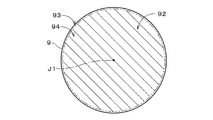
- FIG. 3 is a bottom view showing the substrate 9.
- parallel diagonal lines are provided on the inner region 94, which is the radial inner region of the peripheral region 93, on the lower surface 92 of the substrate 9, and the peripheral region 93 and the inner region 94 are The boundary of is indicated by a two-dot chain line.
- the peripheral region 93 (that is, the bevel portion) is a substantially annular region centered on the central axis J1.
- the inner region 94 is a substantially circular region centered on the central axis J1.
- a structure for example, a circuit pattern used in a product, which is a collection of a large number of fine structure elements, is formed in advance in the inner region 94.
- the structure is not formed in the peripheral region 93.
- the diameter and thickness of the substrate 9 are 300 mm and 775 ⁇ m, respectively.
- the vertical cross section of the peripheral edge of the substrate 9 is substantially arcuate, and the radius of the peripheral edge is 300 ⁇ m.
- the radial width of the peripheral region 93 is substantially constant in the circumferential direction, for example, 2 mm to 3 mm.
- the chemical solution is, for example, a mixed solution of hydrofluoric acid (HF) and nitric acid (HNO3), concentrated hydrofluoric acid, dilute hydrofluoric acid, and ammonium hydroxide (NH4OH).
- HF hydrofluoric acid
- HNO3 nitric acid
- NH4OH ammonium hydroxide
- TMAH tetramethylammonium hydroxide
- SC1 a mixed aqueous solution of ammonia (NH3) and nitric acid (H2O2)
- the chemical solution is, for example, SC2 (that is, hydrogen chloride (HCl)).
- SC2 that is, hydrogen chloride (HCl)
- a mixed aqueous solution of hydrogen fluoride) or FPM that is, a mixed aqueous solution of hydrogen fluoride and hydrogen peroxide
- SiO2 silicon oxide
- dilute hydrofluoric acid or FPM is used as the chemical solution.
- the gas supply unit 6 includes a third nozzle 63.
- the third nozzle 63 is connected to the gas supply source 65 via the pipe 64.
- the third nozzle 63 is a gas discharge unit that discharges the gas delivered from the gas supply source 65 toward the central portion of the lower surface 92 of the substrate 9.
- an inert gas such as nitrogen (N2) gas, dry air or the like is used.
- the gas supply source 65 may be included in the gas supply unit 6.
- the substrate processing apparatus 1 first, the substrate 9 on which the film is formed over substantially the entire surface of the lower surface 92 is held in a horizontal state by the substrate holding portion 31. Subsequently, the substrate rotation mechanism 33 starts the rotation of the substrate 9 (step S11). Then, by controlling the gas supply unit 6 by the supply control unit 72, gas (for example, nitrogen gas) is discharged from the third nozzle 63 to the rotating substrate 9. The gas from the third nozzle 63 is supplied to the central portion of the lower surface 92 of the substrate 9 and spreads radially outward along the lower surface 92 of the substrate 9 (step S12). As a result, on the lower surface 92 of the substrate 9, the air flow of the gas from the central portion to the outer side in the radial direction is formed over the entire circumferential direction.
- gas for example, nitrogen gas
- a predetermined flow rate for example, 1000 ml / min to 2000 ml / min
- the rinse liquid is discharged at the “first flow rate”.
- DIW is used as the rinsing solution.
- the rotation speed of the substrate 9 is, for example, 800 rpm.
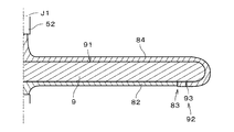
- the rinse liquid 81 from the first nozzle 51 is supplied to the central portion of the upper surface 91 of the substrate 9, and spreads radially outward on the upper surface 91 of the substrate 9 by centrifugal force.
- the rinse liquid 81 that has reached the peripheral edge of the substrate 9 wraps around to the lower surface 92 via the peripheral edge and is supplied to the peripheral edge region 93.
- a liquid film of a rinse liquid 81 continuous from the central portion of the upper surface 91 to the peripheral region 93 of the lower surface 92 is formed.
- the thickness of the substrate 9 and the like is drawn larger than the size in the radial direction. Further, the radial width of the peripheral region 93 is drawn larger than the actual width. The same applies to FIGS. 6 and 7 described later.
- the movement of the rinse liquid 81 around the lower surface 92 of the substrate 9 inward in the radial direction is stopped by the above-mentioned airflow 82 outward in the radial direction.
- the interface between the rinse liquid 81 and the air flow 82 that is, the gas (hereinafter, “gas”).
- the liquid interface 83 is formed (step S13).
- the shape of the gas-liquid interface 83 in a plan view is a substantially circular shape centered on the central axis J1.
- the rinse liquid supply unit 55 is controlled by the supply control unit 72, so that the discharge of the rinse liquid 81 from the first nozzle 51 is stopped, and at the same time, the first A predetermined flow rate (for example, 300 ml / min to 800 ml / min) that is smaller than the flow rate of the rinse liquid 81 in step S13 with respect to the substrate 9 rotating from the two nozzles 52, and is referred to as “third flow rate” in the following description.
- the rinse liquid 81 is discharged at (also referred to as). In other words, the discharge of the rinse liquid 81 from the first nozzle 51 is switched to the discharge of the rinse liquid 81 having a small flow rate from the second nozzle 52.
- the rinse liquid 81 is supplied from the rinse liquid supply source 551 to the second nozzle 52 via the mixing unit 545.
- DIW is used as the rinsing solution 81.
- the rotation speed of the substrate 9 is reduced so as to be slightly slower than step S13 (for example, 700 rpm).
- the rinse liquid 81 from the second nozzle 52 is supplied to the central portion of the upper surface 91 of the substrate 9, and the liquid film of the rinse liquid 81 formed on the substrate 9 in step S13 (FIG. 5). (See), and it spreads radially outward on the upper surface 91 of the substrate 9 by centrifugal force.
- the rinse liquid 81 that has reached the peripheral edge of the substrate 9 wraps around to the lower surface 92 via the peripheral edge and is supplied to the peripheral edge region 93.
- the rinse liquid 81 that wraps around the lower surface 92 of the substrate 9 reaches the above-mentioned gas-liquid interface 83 and comes into contact with the air flow 82 at the gas-liquid interface 83 (step S14). In other words, in step S14, the flow rate of the rinse liquid 81 supplied to the upper surface 91 of the substrate 9 is reduced while maintaining the radial position of the gas-liquid interface 83.
- the gas-liquid interface 83 is stably formed by the rinse liquid 81 having a relatively large flow rate in step S13, the gas-liquid interface 83 is formed even if the flow rate of the rinse liquid 81 is reduced in step S14.
- the radial position of is maintained.
- the supply of the rinse liquid from the second nozzle 52 to the substrate 9 is continued for a predetermined time (for example, 3 seconds), so that the rinse liquid 81 having a relatively small flow rate is supplied to the upper surface 91 of the substrate 9. ,
- the position of the gas-liquid interface 83 in the radial direction can be stabilized.
- the drug solution supply unit 54 is controlled by the supply control unit 72, so that the drug solution stock solution is sent from the stock solution supply source 546 to the mixing unit 545.
- the mixing unit 545 the above-mentioned chemical solution is produced by dissolving the chemical solution stock solution in the rinse solution supplied from the rinse solution supply source 551 to the mixing section 545.
- the chemical solution is discharged from the second nozzle 52 to the rotating substrate 9.
- the flow rate of the rinse liquid supplied from the rinse liquid supply source 551 to the mixing unit 545 is, for example, the same as the flow rate in step S14.
- the flow rate of the chemical solution supplied to the substrate 9 (also referred to as “second flow rate” in the following description) is the sum of the flow rate of the rinse solution in step S14 and the flow rate of the chemical solution stock solution from the stock solution supply source 546. Is.
- the flow rate of the chemical solution stock solution added to the rinse solution in the mixing unit 545 is much smaller than the flow rate of the rinse solution
- the flow rate of the chemical solution supplied to the substrate 9 is the same as the flow rate of the rinse solution in step S14. It is virtually the same.
- the rotation speed of the substrate 9 when supplying the chemical solution is, for example, the same as in step S14.
- the chemical solution 84 from the second nozzle 52 is supplied to the central portion of the upper surface 91 of the substrate 9, and the liquid film of the rinse solution 81 formed on the substrate 9 in step S14 (see FIG. 6). ), And spreads radially outward on the upper surface 91 of the substrate 9 by centrifugal force.
- the chemical solution 84 that has reached the peripheral edge of the substrate 9 wraps around to the lower surface 92 via the peripheral edge and is supplied to the peripheral edge region 93.
- the chemical solution 84 that wraps around the lower surface 92 of the substrate 9 reaches the above-mentioned gas-liquid interface 83 and comes into contact with the air flow 82 at the gas-liquid interface 83 (step S15).
- step S15 the liquid film of the rinse liquid 81 on the upper surface 91 and the lower surface 92 of the substrate 9 is replaced with the chemical liquid 84 while maintaining the radial position of the gas-liquid interface 83. Then, by continuing the supply of the chemical solution 84 to the substrate 9 for a predetermined time, the chemical solution treatment (for example, etching treatment with an etching solution) is performed on the peripheral region 93.
- the chemical solution treatment for example, etching treatment with an etching solution
- the chemical solution supply unit 54 and the rinse solution supply unit 55 are controlled by the supply control unit 72, so that the discharge of the chemical solution from the second nozzle 52 is stopped, and at the same time, the first nozzle 51
- the rinse liquid is discharged from the rotating substrate 9.
- the discharge of the chemical liquid from the second nozzle 52 is switched to the discharge of the rinse liquid from the first nozzle 51.
- the upper surface 91 and the lower surface 92 of the substrate 9 are rinsed (step S16).
- the supply of the rinsing liquid is stopped, and the substrate 9 is dried (step S17).
- the rotation speed of the substrate 9 is increased, and the processing liquid remaining on the substrate 9 is scattered from the edge of the substrate 9 to the outside in the radial direction by centrifugal force and is removed from the substrate 9.
- the treatment liquids such as the chemical liquid and the rinsing liquid scattered radially outward from the substrate 9 during the above steps S13 to S17 are received by the cup portion 4 and discharged to the outside of the housing 11.
- the substrate 9 that has been dried is carried out from the substrate processing apparatus 1.
- the processes of steps S11 to S17 described above are sequentially performed on the plurality of substrates 9.
- the processing liquid that is, the rinsing liquid and the chemical liquid
- the gas is supplied to the lower surface 92 of the substrate 9.
- the chemical solution treatment of the peripheral region 93 of the lower surface 92 is performed, but the treatment for the substrate 9 may be upside down.
- the first nozzle 51 and the second nozzle 52 are arranged so as to face the lower surface 92 of the substrate 9, and the third nozzle 63 is arranged so as to face the upper surface 91 of the substrate 9. ..
- step S12 gas is supplied to the central portion of the lower surface 92 of the substrate 9, and in steps S13 to S16, a rinse solution or a chemical solution is supplied to the central portion of the upper surface 91 of the substrate 9. Then, a gas-liquid interface 83 is formed at the boundary between the peripheral region 93 of the upper surface 91 of the substrate 9 and the inner region 94, and the chemical treatment is performed on the peripheral region 93 of the upper surface 91.
- the above-described substrate processing method includes a step (step S11) of rotating the substrate 9 held in the horizontal state about the central axis J1 facing in the vertical direction, and an upper surface of the rotating substrate 9.
- a gas is supplied to the central portion of one of the main surfaces (for example, the lower surface 92) of the 91 and the lower surface 92, and the rinse liquid is supplied to the central portion of the other main surface (for example, the upper surface 91) of the substrate 9 at a first flow rate.
- step S13 To form a gas-liquid interface 83 between the gas and the rinse liquid on the one main surface by wrapping around the peripheral region 93 of the one main surface (step S13), and more than step S13.
- step S15 of supplying the chemical solution to the gas-liquid interface 83 on the one main surface and performing the chemical solution treatment in the peripheral region 93 is provided.
- the flow rate of the chemical solution supplied to the substrate 9 is set to a relatively small flow rate (that is, the second flow rate), so that the chemical solution scattered from the substrate 9 to the surroundings can be generated. It is possible to prevent the cup portion 4 or the like from bouncing back and adhering to the substrate 9 or the like (so-called liquid splashing). Further, before the chemical treatment on the peripheral region 93 is performed, a relatively large flow rate (that is, the first flow rate) of the rinse liquid is supplied to the substrate 9 to form a gas-liquid interface 83 on the inner peripheral edge of the peripheral region 93.
- the chemical solution can reach the inner peripheral edge of the peripheral edge region 93 over the entire circumference and can be applied to the entire peripheral edge region 93. Therefore, the chemical treatment of the peripheral region 93 of the substrate 9 can be suitably performed while suppressing the splashing of the chemical liquid.
- the chemical solution is applied to the inner peripheral edge of the peripheral edge region 93 all around. It is difficult to reach the gas-liquid interface 83 over, and it is also difficult to stably form the gas-liquid interface 83 on the inner peripheral edge.
- the chemical solution is preferably a rinse solution in which a solute (for example, a drug solution stock solution) is dissolved.
- a solute for example, a drug solution stock solution
- the chemical solution can be easily produced by generating the chemical solution using the rinse solution used in the treatment of the substrate 9.
- the structure of the processing liquid supply unit 5 in the above-mentioned substrate processing apparatus 1 can be simplified.
- the solvent of the chemical solution is the same type of liquid as the liquid film of the rinse solution formed on the substrate 9 in step S14, it is easy to replace the rinse solution with the chemical solution on the substrate 9 in step S15. You can also do it.
- the above-mentioned substrate processing method preferably has a flow rate smaller than that of the first flow rate in the central portion of the other main surface (for example, the upper surface 91) of the rotating substrate 9 between steps S13 and S15.
- a step (step S14) of supplying the rinse liquid at the third flow rate, wrapping around the peripheral region 93 of the one main surface (for example, the lower surface 92), and supplying the rinse liquid to the gas-liquid interface 83 is further provided.
- the liquid film of the rinse liquid on the substrate 9 can be thinned.
- the rinse solution is replaced by the chemical solution in step S15, it is possible to prevent the mixed solution of the chemical solution and the rinse solution from rebounding at the cup portion 4 or the like and adhering to the substrate 9 or the like.
- the second flow rate of the chemical solution in step S15 is preferably produced by dissolving the solute in the rinse solution of the third flow rate.
- the control of the chemical liquid supply unit 54 by the supply control unit 72 can be simplified.
- step S15 the rinse solution on the substrate 9 can be easily replaced with the chemical solution.
- step S15 it is possible to further suppress the splashing of the chemical solution during the chemical treatment of the substrate 9.
- the rotation speed of the substrate 9 is reduced between step S13 and step S14, the radial direction of the gas-liquid interface 83 is performed when the rinse liquid having a relatively small flow rate is supplied in step S14.
- the position of can be easily maintained on the inner peripheral edge of the peripheral area 93.
- the reduction of the rotation speed of the substrate 9 may be performed in parallel with the start of step S15. Even in this case, similarly to the above, in step S15, the rinse solution on the substrate 9 can be easily replaced with the chemical solution. In addition, it is possible to further suppress the splashing of the chemical solution during the chemical treatment of the substrate 9.
- the above-mentioned substrate processing device 1 includes a substrate holding unit 31, a substrate rotating mechanism 33, a gas supply unit 6, a rinse liquid supply unit 55, and a chemical liquid supply unit 54.
- the substrate holding portion 31 holds the substrate 9 in a horizontal state.
- the substrate rotation mechanism 33 rotates the substrate holding portion 31 around the central axis J1 that faces in the vertical direction.
- the gas supply unit 6 supplies gas to the central portion of one of the main surfaces (for example, the lower surface 92) of the upper surface 91 and the lower surface 92 of the rotating substrate 9.
- the rinse liquid supply unit 55 supplies the rinse liquid to the central portion of the other main surface (for example, the upper surface 91) of the rotating substrate 9 at the first flow rate and wraps around the peripheral region 93 of the one main surface.
- a gas-liquid interface 83 between the gas and the rinse liquid is formed on the one main surface.
- the chemical supply unit 54 supplies the chemical liquid to the central portion of the other main surface of the rotating substrate 9 at a second flow rate smaller than the first flow rate, and supplies the chemical liquid to the peripheral region 93 of the one main surface.
- the chemical solution is supplied to the gas-liquid interface 83 on the one main surface, and the chemical solution treatment of the peripheral region 93 is performed.
- the chemical treatment of the peripheral region 93 of the substrate 9 can be suitably performed while suppressing the splashing of the chemical liquid.
- step S15 the flow rate of the rinse liquid supplied from the rinse liquid supply source 551 to the mixing unit 545 does not necessarily have to be the same as the flow rate of the rinse liquid in step S14, and may be changed as appropriate.
- the reduction in the rotation speed of the substrate 9 between steps S13 and S15 does not necessarily have to be performed.
- the rotation speed of the substrate 9 in steps S13 to S15 may be the same.
- step S14 may be omitted and step S15 may be performed.
- the chemical solution does not necessarily have to be generated in the mixing unit 545, and the chemical solution may be sent to the second nozzle 52 from the chemical solution supply source that stores the previously generated chemical solution.
- the mixing unit 545 may be omitted.
- the rinse liquid discharge in step S14 may be performed by the first nozzle 51. Further, the rinse liquid discharge in steps S13 to S14 and the chemical liquid discharge in step S15 may be performed by the same nozzle.
- the above-mentioned substrate processing device 1 is used for a liquid crystal display device, a glass substrate used for a flat display device (Flat Panel Display) such as an organic EL (Electro Luminescence) display device, or another display device. It may be used for processing a glass substrate to be processed. Further, the above-mentioned substrate processing device 1 may be used for processing an optical disk substrate, a magnetic disk substrate, a magneto-optical disk substrate, a photomask substrate, a ceramic substrate, a solar cell substrate, and the like.
- a flat display device such as an organic EL (Electro Luminescence) display device
- the above-mentioned substrate processing device 1 may be used for processing an optical disk substrate, a magnetic disk substrate, a magneto-optical disk substrate, a photomask substrate, a ceramic substrate, a solar cell substrate, and the like.
Landscapes
- Cleaning Or Drying Semiconductors (AREA)
- Weting (AREA)
- Manufacturing Of Printed Circuit Boards (AREA)
Abstract
Description
6 ガス供給部
9 基板
31 基板保持部
33 基板回転機構
54 薬液供給部
55 リンス液供給部
81 リンス液
82 気流
83 気液界面
84 薬液
91 上面
92 下面
93 周縁領域
545 混合部
J1 中心軸
S11~S17 ステップ
Claims (8)
- 基板処理方法であって、
a)水平状態で保持された基板を、上下方向を向く中心軸を中心として回転させる工程と、
b)回転中の前記基板の上面および下面のうち一方の主面の中央部にガスを供給するとともに、前記基板の他方の主面の中央部に第1流量にてリンス液を供給して前記一方の主面の周縁領域に回り込ませることにより、前記一方の主面上において前記ガスと前記リンス液との気液界面を形成する工程と、
c)前記b)工程よりも後に、回転中の前記基板の前記他方の主面の中央部に、前記第1流量よりも小流量の第2流量にて薬液を供給して前記一方の主面の前記周縁領域に回り込ませることにより、前記一方の主面上において前記気液界面まで前記薬液を供給して前記周縁領域の薬液処理を行う工程と、
を備える。 - 請求項1に記載の基板処理方法であって、
前記薬液は、前記リンス液に溶質を溶解させたものである。 - 請求項1または2に記載の基板処理方法であって、
d)前記b)工程と前記c)工程との間に、回転中の前記基板の前記他方の主面の中央部に、前記第1流量よりも小流量の第3流量にて前記リンス液を供給して前記一方の主面の前記周縁領域に回り込ませ、前記気液界面まで前記リンス液を供給する工程をさらに備える。 - 請求項3に記載の基板処理方法であって、
前記c)工程における前記第2流量の前記薬液は、前記第3流量の前記リンス液に溶質を溶解させることにより生成される。 - 請求項1ないし4のいずれか1つに記載の基板処理方法であって、
前記b)工程と前記c)工程との間において、または、前記c)工程の開始と並行して、前記基板の回転速度が低減される。 - 基板処理装置であって、
水平状態で基板を保持する基板保持部と、
上下方向を向く中心軸を中心として前記基板保持部を回転する基板回転機構と、
回転中の前記基板の上面および下面のうち一方の主面の中央部にガスを供給するガス供給部と、
回転中の前記基板の他方の主面の中央部に第1流量にてリンス液を供給して前記一方の主面の周縁領域に回り込ませることにより、前記一方の主面上において前記ガスと前記リンス液との気液界面を形成するリンス液供給部と、
回転中の前記基板の前記他方の主面の中央部に、前記第1流量よりも小流量の第2流量にて薬液を供給して前記一方の主面の前記周縁領域に回り込ませることにより、前記一方の主面上において前記気液界面まで前記薬液を供給して前記周縁領域の薬液処理を行う薬液供給部と、
を備える。 - 請求項6に記載の基板処理装置であって、
前記リンス液供給部による前記第1流量での前記リンス液の供給と、前記薬液供給部による前記薬液の供給との間において、前記リンス液供給部が、回転中の前記基板の前記他方の主面の中央部に、前記第1流量よりも小流量の第3流量にて前記リンス液を供給して前記一方の主面の前記周縁領域に回り込ませ、前記気液界面まで前記リンス液を供給する。 - 請求項7に記載の基板処理装置であって、
前記薬液供給部は、前記第3流量の前記リンス液に溶質を溶解させることにより前記第2流量の前記薬液を生成する薬液生成部を備える。
Priority Applications (2)
| Application Number | Priority Date | Filing Date | Title |
|---|---|---|---|
| CN202080020030.2A CN113557594B (zh) | 2019-03-20 | 2020-02-06 | 基板处理方法以及基板处理装置 |
| KR1020217031485A KR102648039B1 (ko) | 2019-03-20 | 2020-02-06 | 기판 처리 방법 및 기판 처리 장치 |
Applications Claiming Priority (2)
| Application Number | Priority Date | Filing Date | Title |
|---|---|---|---|
| JP2019-052732 | 2019-03-20 | ||
| JP2019052732A JP7201494B2 (ja) | 2019-03-20 | 2019-03-20 | 基板処理方法および基板処理装置 |
Publications (1)
| Publication Number | Publication Date |
|---|---|
| WO2020189072A1 true WO2020189072A1 (ja) | 2020-09-24 |
Family
ID=72519277
Family Applications (1)
| Application Number | Title | Priority Date | Filing Date |
|---|---|---|---|
| PCT/JP2020/004588 Ceased WO2020189072A1 (ja) | 2019-03-20 | 2020-02-06 | 基板処理方法および基板処理装置 |
Country Status (5)
| Country | Link |
|---|---|
| JP (1) | JP7201494B2 (ja) |
| KR (1) | KR102648039B1 (ja) |
| CN (1) | CN113557594B (ja) |
| TW (1) | TWI787582B (ja) |
| WO (1) | WO2020189072A1 (ja) |
Families Citing this family (1)
| Publication number | Priority date | Publication date | Assignee | Title |
|---|---|---|---|---|
| CN117316812B (zh) * | 2023-08-14 | 2024-11-26 | 深圳远荣半导体设备有限公司 | 一种晶圆清洗机及晶圆搬运的方法 |
Citations (3)
| Publication number | Priority date | Publication date | Assignee | Title |
|---|---|---|---|---|
| JP2003273063A (ja) * | 2002-03-13 | 2003-09-26 | Komatsu Electronic Metals Co Ltd | 半導体ウェーハのエッジ部の酸化膜除去装置および方法 |
| JP2009266951A (ja) * | 2008-04-23 | 2009-11-12 | Dainippon Screen Mfg Co Ltd | 基板処理方法および基板処理装置 |
| JP2012064894A (ja) * | 2010-09-17 | 2012-03-29 | Tokyo Electron Ltd | 液処理方法、その液処理方法を実行させるためのプログラムを記録した記録媒体及び液処理装置 |
Family Cites Families (10)
| Publication number | Priority date | Publication date | Assignee | Title |
|---|---|---|---|---|
| JP3745214B2 (ja) | 2000-09-27 | 2006-02-15 | 大日本スクリーン製造株式会社 | ベベルエッチング装置およびベベルエッチング方法 |
| JP3917393B2 (ja) | 2001-08-29 | 2007-05-23 | 大日本スクリーン製造株式会社 | 基板処理装置 |
| JP4342343B2 (ja) * | 2004-02-26 | 2009-10-14 | 大日本スクリーン製造株式会社 | 基板処理装置および基板処理方法 |
| JP4446875B2 (ja) * | 2004-06-14 | 2010-04-07 | 大日本スクリーン製造株式会社 | 基板処理装置 |
| JP5615650B2 (ja) * | 2010-09-28 | 2014-10-29 | 大日本スクリーン製造株式会社 | 基板処理方法および基板処理装置 |
| JP6226297B2 (ja) * | 2014-03-26 | 2017-11-08 | 株式会社Screenホールディングス | 基板処理装置 |
| JP6273178B2 (ja) * | 2014-08-13 | 2018-01-31 | 東京エレクトロン株式会社 | 基板処理装置および基板処理方法 |
| JP6718714B2 (ja) * | 2016-03-25 | 2020-07-08 | 株式会社Screenホールディングス | 基板処理方法および基板処理装置 |
| JP6916003B2 (ja) * | 2017-02-24 | 2021-08-11 | 株式会社Screenホールディングス | 基板処理方法および基板処理装置 |
| JP7034634B2 (ja) * | 2017-08-31 | 2022-03-14 | 株式会社Screenホールディングス | 基板処理方法および基板処理装置 |
-
2019
- 2019-03-20 JP JP2019052732A patent/JP7201494B2/ja active Active
-
2020
- 2020-02-06 WO PCT/JP2020/004588 patent/WO2020189072A1/ja not_active Ceased
- 2020-02-06 CN CN202080020030.2A patent/CN113557594B/zh active Active
- 2020-02-06 KR KR1020217031485A patent/KR102648039B1/ko active Active
- 2020-02-14 TW TW109104616A patent/TWI787582B/zh active
Patent Citations (3)
| Publication number | Priority date | Publication date | Assignee | Title |
|---|---|---|---|---|
| JP2003273063A (ja) * | 2002-03-13 | 2003-09-26 | Komatsu Electronic Metals Co Ltd | 半導体ウェーハのエッジ部の酸化膜除去装置および方法 |
| JP2009266951A (ja) * | 2008-04-23 | 2009-11-12 | Dainippon Screen Mfg Co Ltd | 基板処理方法および基板処理装置 |
| JP2012064894A (ja) * | 2010-09-17 | 2012-03-29 | Tokyo Electron Ltd | 液処理方法、その液処理方法を実行させるためのプログラムを記録した記録媒体及び液処理装置 |
Also Published As
| Publication number | Publication date |
|---|---|
| TWI787582B (zh) | 2022-12-21 |
| KR102648039B1 (ko) | 2024-03-18 |
| CN113557594A (zh) | 2021-10-26 |
| TW202036707A (zh) | 2020-10-01 |
| KR20210133288A (ko) | 2021-11-05 |
| JP2020155588A (ja) | 2020-09-24 |
| JP7201494B2 (ja) | 2023-01-10 |
| CN113557594B (zh) | 2025-04-15 |
Similar Documents
| Publication | Publication Date | Title |
|---|---|---|
| JP5615650B2 (ja) | 基板処理方法および基板処理装置 | |
| JP4339561B2 (ja) | 基板処理装置および基板処理方法 | |
| JP5270607B2 (ja) | 基板処理装置 | |
| JP4767138B2 (ja) | 基板処理装置、液膜凍結方法および基板処理方法 | |
| JP6379400B2 (ja) | 基板処理方法および基板処理装置 | |
| US9852914B2 (en) | Sacrificial-film removal method and substrate processing device | |
| WO2015053329A1 (ja) | 基板処理方法および基板処理装置 | |
| JP6934376B2 (ja) | 基板処理方法および基板処理装置 | |
| TW201523163A (zh) | 基板處理方法及基板處理裝置 | |
| JP2013172080A (ja) | 基板処理装置および基板処理方法 | |
| JP2005268308A (ja) | レジスト剥離方法およびレジスト剥離装置 | |
| JP7201494B2 (ja) | 基板処理方法および基板処理装置 | |
| JP2009054959A (ja) | 基板処理装置 | |
| JP2020155603A (ja) | 基板処理方法および基板処理装置 | |
| JP2002359227A (ja) | 基板処理装置および基板処理方法 | |
| JP2018049918A (ja) | 評価用サンプル製造方法、評価用サンプル製造装置および基板処理装置 | |
| KR20200040538A (ko) | 기판 세정 장치 | |
| JP2007318016A (ja) | 基板処理方法および基板処理装置 | |
| JP2009194090A (ja) | 基板処理方法および基板処理装置 | |
| JP2009105145A (ja) | 基板処理装置 | |
| JP7809031B2 (ja) | 基板処理方法および基板処理装置 | |
| JP2006351805A (ja) | 基板処理方法および基板処理装置 | |
| KR20200077118A (ko) | 기판 세정 장치 | |
| JP6268410B2 (ja) | 基板処理装置および基板処理方法 | |
| JP2020136296A (ja) | 基板処理装置および基板処理方法 |
Legal Events
| Date | Code | Title | Description |
|---|---|---|---|
| 121 | Ep: the epo has been informed by wipo that ep was designated in this application |
Ref document number: 20773564 Country of ref document: EP Kind code of ref document: A1 |
|
| NENP | Non-entry into the national phase |
Ref country code: DE |
|
| ENP | Entry into the national phase |
Ref document number: 20217031485 Country of ref document: KR Kind code of ref document: A |
|
| 122 | Ep: pct application non-entry in european phase |
Ref document number: 20773564 Country of ref document: EP Kind code of ref document: A1 |
|
| WWG | Wipo information: grant in national office |
Ref document number: 202080020030.2 Country of ref document: CN |