WO2020184536A1 - カバー部材及びカバー部材取付構造 - Google Patents
カバー部材及びカバー部材取付構造 Download PDFInfo
- Publication number
- WO2020184536A1 WO2020184536A1 PCT/JP2020/010166 JP2020010166W WO2020184536A1 WO 2020184536 A1 WO2020184536 A1 WO 2020184536A1 JP 2020010166 W JP2020010166 W JP 2020010166W WO 2020184536 A1 WO2020184536 A1 WO 2020184536A1
- Authority
- WO
- WIPO (PCT)
- Prior art keywords
- door
- cover member
- opening
- panel
- glass run
- Prior art date
- Legal status (The legal status is an assumption and is not a legal conclusion. Google has not performed a legal analysis and makes no representation as to the accuracy of the status listed.)
- Ceased
Links
Images





Classifications
-
- B—PERFORMING OPERATIONS; TRANSPORTING
- B60—VEHICLES IN GENERAL
- B60J—WINDOWS, WINDSCREENS, NON-FIXED ROOFS, DOORS, OR SIMILAR DEVICES FOR VEHICLES; REMOVABLE EXTERNAL PROTECTIVE COVERINGS SPECIALLY ADAPTED FOR VEHICLES
- B60J10/00—Sealing arrangements
- B60J10/70—Sealing arrangements specially adapted for windows or windscreens
- B60J10/74—Sealing arrangements specially adapted for windows or windscreens for sliding window panes, e.g. sash guides
- B60J10/76—Sealing arrangements specially adapted for windows or windscreens for sliding window panes, e.g. sash guides for window sashes; for glass run channels
-
- B—PERFORMING OPERATIONS; TRANSPORTING
- B60—VEHICLES IN GENERAL
- B60J—WINDOWS, WINDSCREENS, NON-FIXED ROOFS, DOORS, OR SIMILAR DEVICES FOR VEHICLES; REMOVABLE EXTERNAL PROTECTIVE COVERINGS SPECIALLY ADAPTED FOR VEHICLES
- B60J5/00—Doors
- B60J5/04—Doors arranged at the vehicle sides
Definitions
- the present disclosure relates to a cover member and a cover member mounting structure.
- Patent Document 1 describes a vehicle door structure.
- the metal door panel that constitutes the vehicle door is provided with a window opening at the top.
- the door panel is composed of a door inner panel and a door outer panel, and both are connected by a door sash at the upper edge portion and both side edge portions of the window opening.
- a glass run that guides the raising and lowering of the door glass is installed inside the door sash.
- a notch is formed in the door outer panel and the door sash so as to cut out the side edge.
- a bracket member for closing the notch is attached to the outer surface side of the door outer panel.
- a notch (notch-shaped opening) for improving the attachment of the door glass to the door panel may be provided around the window opening of the door inner panel.
- a bracket member (cover member) as in the vehicle door structure described in Patent Document 1
- the water will enter the passenger compartment side from between the opening and the cover member.
- the present disclosure provides a cover member and a cover member mounting structure capable of suppressing the ingress of water from the opening of the door inner panel to the passenger compartment side.
- the first aspect of the present invention is a plate-like door panel, which is attached to a door panel that stands up along a predetermined direction in a state where the door inner space is partitioned by a door inner panel on the passenger compartment side and a door outer panel on the outer side. It is a cover member that closes the opening provided in the door inner panel from the passenger compartment side, and includes a slit portion, a passenger compartment side region, and a door interior region. The slit portion extends upward from the lower end edge of the cover member, and the opening edge below the opening of the door inner panel can be inserted.
- the vehicle interior side region is located on one side of the lower end portion of the cover member in the predetermined direction with respect to the slit portion, and is arranged on the vehicle interior side with respect to the door inner panel.
- the door inner region is located on the other side of the lower end portion of the cover member in the predetermined direction with respect to the slit portion, and is arranged in the door inner space.
- a region (inside the door area) of the lower end portion of the cover member located on the other side of the slit portion in the predetermined direction is arranged in the inside space of the door, so that the area flows down along the cover member in the inside space of the door.
- the water that flows down the region on the other side of the cover member in the predetermined direction flows down from the lower end of the cover member to the lower part of the space inside the door and does not enter the passenger compartment side. Therefore, it is possible to suppress the intrusion of water from the opening of the door inner panel to the vehicle interior side.
- the cover member is used when the opening of the door inner panel is closed by the cover member.
- the cover member can be easily positioned downward with respect to the opening of the door inner panel.
- the second aspect of the present invention is the cover member of the first aspect, which includes a protruding portion.
- the protruding portion is arranged above the slit portion and projects toward the space inside the door.
- the other end of the protruding portion in the predetermined direction is arranged on the other side of the slit portion.
- At least one of the upper surface and the lower surface of the projecting portion is inclined downward from the one side to the other side in the predetermined direction.
- the other end in the predetermined direction of the protrusion protruding toward the space inside the door above the slit is arranged on the other side of the slit, and at least one of the upper surface and the lower surface of the protrusion. However, it is inclined downward from one side in the predetermined direction to the other side. That is, at least one of the upper surface and the lower surface of the protruding portion is inclined from above toward the door inner region side of the cover member. Therefore, when the upper surface of the protruding portion is inclined toward the door inner region side of the cover member, the water flowing down in the door panel is allowed to flow from the one side along the upper surface of the protruding portion from the door inner region of the cover member.
- a third aspect of the present invention is a cover member mounting structure for mounting the cover member of the first aspect or the second aspect to the door panel, and the door panel has a door trim.
- the door trim is arranged closer to the passenger compartment than the door inner panel and is fixed to the door inner panel.
- the cover member is attached to the door panel by being sandwiched between the door inner panel and the door trim.
- the cover member since the cover member is sandwiched between the door inner panel and the door trim, the cover member can function as a seal member for preventing water from entering the passenger compartment side.
- cover member is attached to the door panel by being sandwiched between the door inner panel and the door trim. Therefore, the number of parts can be reduced as compared with the case where the cover member is attached to the peripheral edge of the opening of the door inner panel with another member (for example, butyl tape or bolt).
- a fourth aspect of the present invention is a cover member mounting structure for mounting the cover member of the first aspect or the second aspect to the door panel, and the door panel is provided in the window opening and the space inside the door. It has a glass run channel that is arranged and fixed to the door panel, and a glass run that is supported by the glass run channel.
- the opening of the door inner panel is provided in a notch shape from the window opening to the one side or the other side in the predetermined direction.
- the glass run channel has a region in the opening extending in the vertical direction on the window opening side in the opening.
- the glass run has a passenger compartment side lip portion that covers the region inside the opening of the glass run channel from the passenger compartment side.
- the cover member is attached to the door panel by being sandwiched between the area inside the opening of the glass run channel and the passenger compartment side lip portion of the glass run.
- the cover member is sandwiched between the area inside the opening of the glass run channel and the lip portion on the passenger compartment side of the glass run, the cover member is used as a sealing member for preventing water from entering the passenger compartment side. Can work.
- the cover member is attached to the door panel by being sandwiched between the area inside the opening of the glass run channel and the lip portion on the passenger compartment side of the glass run. Therefore, for example, the thickness of the attachment portion in the direction intersecting with the door inner panel can be suppressed as compared with the case where the cover member is attached to the glass run channel with butyl tape or the like. Further, the number of parts can be reduced as compared with the case where the cover member is attached to the peripheral edge of the opening of the door inner panel with another member (for example, butyl tape or bolt).
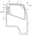
- FIG. 1A is a side view of a side door of a vehicle to which the cover member mounting structure according to the embodiment of the present invention is applied, and shows a state viewed from the outside in the vehicle width direction.
- FIG. 1B is a side view of a side door of a vehicle to which the cover member mounting structure according to the embodiment of the present invention is applied, and shows a state viewed from the inside in the vehicle width direction.
- FIG. 2 is a side view of the side door with the door trim of FIG. 1B removed.
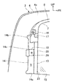
- FIG. 3A is an enlarged view of the opening of the door inner panel, showing a state in which the cover member and the glass run are removed.
- FIG. 3B is an enlarged view of the opening of the door inner panel, showing a state in which the cover member and the glass run are attached.
- FIG. 4 is a side view of the cover member.
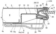
- FIG. 5 is a sectional view taken along line VV of FIG. 1B.
- FIG. 6 is a sectional view taken along line VI-VI of FIG. 1B.
- FR indicates the front of the vehicle
- UP indicates the upper side
- IN indicates the inner side in the vehicle width direction.
- front-rear direction means the front-rear direction of the vehicle
- left-right direction means the left-right direction in a state of facing the front of the vehicle.
- the cover member mounting structure has a side door (door panel) 3 capable of opening and closing the passenger compartment 2 (see FIG. 5) of the vehicle 1 to the outside. Applies to.
- the side door 3 stands up in the front-rear direction (predetermined direction) intersecting the vehicle width direction in a closed state in which the side of the vehicle interior 2 is closed.
- the front-rear direction and the left-right direction of the side door 3 indicate the direction of the side door 3 in the closed state.
- the side door 3 has a door inner panel 4 on the vehicle interior 2 side (inside in the vehicle width direction in the present embodiment) intersecting with the vehicle width direction and an external side (in the present embodiment, the vehicle width direction) intersecting with the vehicle width direction. It is formed in a closed cross section by the door outer panel 5 (outside). With the outer peripheral edge of the door inner panel 4 and the outer peripheral edge of the door outer panel 5 fixed to each other, a door inner space 9 (see FIG. 5) is partitioned between the door inner panel 4 and the door outer panel 5. Will be done.
- a door trim 6 which is a decorative member is attached to the inside of the door inner panel 4 in the vehicle width direction (on the vehicle interior 2 side).
- a window opening 7 is formed in the upper part of the side door 3.
- the window opening 7 can be opened and closed by a window glass 8 that is vertically supported by a glass elevating mechanism (not shown) in the door inner space 9.
- a glass run 12 for guiding the ascending / descending window glass 8 is provided on the peripheral edge of the window opening 7, and a glass run channel 13 supporting the glass run 12 (in the space 9 in the door on the peripheral edge of the window opening 7) (See FIG. 3A) is provided.
- a notch (opening) 14 cut out rearward from the trailing edge 16 of the window opening 7 is formed behind the window opening 7 in the door inner panel 4.
- the notch 14 is provided to improve workability when the window glass 8 is inserted into the lower door inner space 9 (see FIG. 5) from the lower edge 15 side of the window opening 7.
- the notch 14 extends rearward from the lower edge (lower opening edge) 14a of the opening along the lower edge 15 of the window opening 7 and the trailing edge 16 of the window opening 7 above the lower edge 14a of the opening. It has an opening upper edge 14b and an opening trailing edge 14c extending in the vertical direction between the rear end of the opening lower edge 14a and the rear end of the opening upper edge 14b.
- a part 20 (hereinafter, a portion) of the glass run channel 13 having a U-shaped cross section (see FIG. 5) that opens forward is in the vertical direction.
- "Region 20 in the opening" extends in the vertical direction.
- a first bracket 17 that supports the glass run channel 13 while being pressed from the inside in the vehicle width direction is fixed to the region of the door inner panel 4 above the opening upper edge 14b of the notch portion 14.
- a second bracket 18 for fixing the door trim 6 is arranged at a substantially central portion in the vertical direction in the notch portion 14.
- the second bracket 18 is provided with a clip attachment portion 28 to which a clip (not shown) on the door trim 6 side can be attached.
- the cutout portion 14 of the door inner panel 4 is inward in the vehicle width direction. It is open. As shown in FIGS. 2 and 3B, the notch 14 of the door inner panel 4 is closed by the cover member 10 from the inside in the vehicle width direction.
- the cover member 10 is formed in a substantially plate shape by a flexible porous material (for example, a sponge material having discontinuous cells).
- a flexible porous material for example, a sponge material having discontinuous cells.
- the cover member 10 is arranged at a predetermined mounting position of the side door 3 before mounting the door trim 6, is supported (sandwiched) by the door trim 6 and the glass run 12, and is mounted on the side door 3. ..
- the cover member 10 closes the notch 14 of the door inner panel 4, and the intrusion of water and dust from the door interior space 9 to the passenger compartment 2 side. It prevents intrusion and suppresses the transmission of noise from the inside of the door space 9 to the passenger compartment 2 side.
- the cover member 10 has a cover lower end 19a, a cover upper end 19b, a cover rear end 19c, and a cover front end 19d.
- the upper end portion 19b of the cover extends upward from the upper edge 14b of the opening of the notch portion 14 in the cover mounted state and comes into contact with the inner side surface 4a of the door inner panel 4 in the vehicle width direction.
- the rear end portion 19c of the cover extends rearward from the opening trailing edge 14c of the notch portion 14 in the cover mounted state and comes into contact with the inner side surface 4a of the door inner panel 4 in the vehicle width direction.
- the front end portion 19d of the cover extends forward from the rear surface 32 (see FIG.
- the lower end portion 19a of the cover extends downward from the lower edge 14a of the opening of the notch 14 of the door inner panel 4 when the cover is attached.
- a slit portion 24 extending upward from the lower end edge 23 of the cover member 10 is formed in the lower end portion 19a of the cover. That is, the lower end portion 19a of the cover has a slit rear region (vehicle interior side region) 25 behind the slit portion 24 (one side) and a slit front region (door inner region) in front of the slit portion 24 (other side). It has 26 and.
- the length L1 in the front-rear direction of the slit front region 26 is set longer than the length L2 in the front-rear direction of the slit rear region 25 (L1> L2).
- the slit rear region 25 of the lower end portion 19a of the cover is inside the door inner panel 4 in the vehicle width direction (vehicle compartment 2 side).
- the slit front region 26 of the lower end portion 19a of the cover is arranged in the door inner space 9 outside the door inner panel 4 in the vehicle width direction.
- a clip insertion hole 29 is formed in a region 27 surrounded by the lower end portion 19a of the cover, the upper end portion 19b of the cover, the rear end portion 19c of the cover, and the front end portion 19d of the cover.
- An upper protruding portion (protruding portion) 30 arranged above the clip insertion hole 29 and projecting outward in the vehicle width direction, and a downward protruding portion 30 arranged below the clip insertion hole 29 and projecting outward in the vehicle width direction.
- a portion (protruding portion) 31 is formed.
- the clip insertion hole 29 is arranged at a position corresponding to the clip attachment portion 28 of the second bracket 18 in the cover-attached state, and allows the insertion of the clip (not shown) on the door trim 6 side.
- the upper protruding portion 30 has a rectangular box-shaped box-shaped portion 30a that opens inward in the vehicle width direction, and a linear linear portion 30b that extends upward from the box-shaped portion 30a.
- the front surface (other end) 33 of the box-shaped portion 30a is arranged near the rear surface 32 of the opening inner region 20 of the glass run channel 13 in a cover-attached state, faces the rear surface 32, and faces the rear surface 32 of the glass run channel 13. It extends vertically along the extension direction.
- the rear surface 47 of the box-shaped portion 30a is arranged near the front of the opening trailing edge 14c of the notch 14 of the door inner panel 4 with the cover attached, and extends in the vertical direction along the extending direction of the opening trailing edge 14c.
- the linear portion 30b has a first linear portion 34 extending upward from the rear upper end of the box-shaped portion 30a, and a second linear portion 35 extending forward from the upper end of the first linear portion 34.
- the first linear portion 34 extends in the vertical direction in the vicinity of the front of the opening trailing edge 14c of the cutout portion 14 of the door inner panel 4, and the upper end of the first linear portion 34 is the opening upper edge 14b of the notch portion 14. It is placed near the bottom of.
- the second linear portion 35 is arranged near the lower side of the opening upper edge 14b of the notch portion 14 and extends back and forth along the extending direction of the opening upper edge 14b.
- the lower protruding portion 31 is formed in a box shape having a substantially rhombic cross section that opens inward in the vehicle width direction.
- the front surface (other end) 36 of the lower protrusion 31 is arranged near the rear surface 32 of the opening inner region 20 of the glass run channel 13 in a cover-attached state, faces the rear surface 32, and faces the rear surface 32. Extends vertically along the extension direction of.
- the rear surface 37 of the lower protruding portion 31 is arranged near the front of the opening trailing edge 14c of the notch 14 of the door inner panel 4 with the cover attached, and extends in the vertical direction along the extending direction of the opening trailing edge 14c.
- the front surface 33 of the box-shaped portion 30a of the upper protrusion portion 30 and the front surface 36 of the lower protrusion portion 31 are arranged in front of the slit portion 24.
- the upper surface 38 and the lower surface 39 of the lower protrusion 31 extend linearly from the rear upper part to the front lower part and are inclined with respect to the front-rear horizontal direction.
- the glass run 12 has a glass entry recess 40 into which the rear end portion of the window glass 8 enters, and a front end edge portion of the door outer panel 5 extending rearward from the front end portion of the glass entry recess 40 outside in the vehicle width direction to the rear outside in the vehicle width direction.
- the outer lip portion 41 that covers from the outside in the vehicle width direction and the front end portion of the glass entry recess 40 inside the vehicle width direction extend rearward in the vehicle width direction and inside the vehicle width direction on the front end side of the glass run channel 13. It has a vehicle interior side lip portion 42 that covers the side surface 22 from the inside in the vehicle width direction.
- a pair of left and right seal lip portions 43, 44 that come into contact with the window glass 8 from both sides in the vehicle width direction are provided.
- the door inner panel 4 and the door outer panel 5 are joined to each other, the window glass 8 is arranged in the door inner space 9, and the glass is placed on the peripheral edge of the window opening 7.
- a run channel 13 and a glass run 12 are provided, and a notch 14 of the door inner panel 4 opens inward in the vehicle width direction.
- the slit rear region 25 of the cover member 10 is arranged inside the door inner panel 4 in the vehicle width direction, and the slit front region 26 is the vehicle of the door inner panel 4.
- the lower edge 14a of the opening of the door inner panel 4 is inserted from below into the slit portion 24 of the cover member 10 so as to be arranged in the door inner space 9 outside in the width direction, and the lower edge 14a of the opening is inserted into the upper end of the slit portion 24. It is brought into contact with 24a.
- the upper protruding portion 30 and the lower protruding portion 31 of the cover member 10 are inserted from the inside in the vehicle width direction between the notch 14 of the door inner panel 4 and the rear surface 32 of the opening inner region 20 of the glass run channel 13.
- the cover member 10 is arranged at the predetermined mounting position, and in such a state, the front surface 33 of the box-shaped portion 30a of the upper protruding portion 30 and the front surface 36 of the lower protruding portion 31 are the glass run channels 13.
- the rear surface 47 of the box-shaped portion 30a and the rear surface 37 of the lower projecting portion 31 are arranged near the rear surface of the rear surface 32 of the opening inner region 20 of the notch portion 14, and are arranged near the front surface of the opening trailing edge 14c of the notch portion 14 and project upward.
- the first linear portion 34 of the portion 30 is arranged near the front of the opening trailing edge 14c of the notch portion 14, and the second linear portion 35 of the upper protruding portion 30 is near the lower side of the opening upper edge 14b of the notch portion 14. Is placed in.
- substantially the entire vertical direction of the cover front end portion 19d of the cover member 10 is sandwiched between the inner side surface 22 of the glass run channel 13 in the vehicle width direction and the vehicle interior side lip portion 42 of the glass run 12.
- the cover member 10 is attached to the side door 3 by being sandwiched between at least the glass run channel 13 and the vehicle interior side lip portion 42 of the glass run 12.
- a clip (not shown) on the door trim 6 side is inserted into the clip insertion hole 29 of the cover member 10 from the inside in the vehicle width direction and locked to the clip attachment portion 28 of the second bracket 18.
- the cover pressing portion 6a of the door trim 6 faces the inner side surface 4a of the door inner panel 4 in the vehicle width direction inside the inner side surface 4a of the door inner panel 4 in the vehicle width direction.
- the slit front region 26 of the cover member 10 is arranged in the door inner space 9 outside the door inner panel 4 in the vehicle width direction, so that water has entered the door inner space 9.
- the water flowing down in front of the slit portion 24 reaches the slit front region 26 and reaches the lower end edge 23 of the slit front region 26. It flows down from the door space 9 below. Therefore, since water does not infiltrate into the passenger compartment 2, it is possible to suppress the intrusion of water from the notch 14 of the door inner panel 4 into the passenger compartment 2.
- the front surface 36 of the lower protrusion 31 is arranged in front of the slit portion 24, and the upper surface 38 of the lower protrusion 31 is inclined from the rear upper side to the front lower side. Therefore, the water that has flowed down the door inner space 9 and reached the upper surface 38 of the lower protrusion 31 of the cover member 10 is guided along the upper surface 38 of the lower protrusion 31 toward the front slit front region 26 side. Therefore, it is possible to suitably suppress the intrusion of water from the notch 14 of the door inner panel 4 to the vehicle interior 2 side.
- the front surface 36 of the lower protrusion 31 is arranged in front of the slit portion 24, and the lower surface 39 of the lower protrusion 31 is inclined from the rear upper side to the front lower side. Therefore, the water that flows down along the rear surface 37 of the lower protrusion 31 of the cover member 10 in the door inner space 9 and reaches the lower surface 39 of the cover member 10 is forward along the lower surface 39 of the lower protrusion 31. Since it is possible to guide the door to the front region 26 side of the slit, it is possible to suitably suppress the intrusion of water from the notch 14 of the door inner panel 4 to the vehicle interior 2 side.
- cover front end 19d of the cover member 10 is sandwiched between the inner side surface 22 of the glass run channel 13 in the vehicle width direction and the vehicle interior side lip portion 42 of the glass run 12, the cover member 10 is placed in the vehicle interior. It can function as a sealing member to prevent water from entering the two sides.
- cover rear end 19c of the cover member 10 (for example, the region whose cross section is shown in FIG. 5) is sandwiched between the door trim 6 and the door inner panel 4, the cover of the cover member 10 is covered.
- the region of the rear end portion 19c sandwiched between the door trim 6 and the door inner panel 4 can function as a sealing member for preventing water from entering the vehicle interior 2.
- cover member 10 is made of a flexible porous material, it can effectively function as a sealing member for preventing water from entering the vehicle interior 2.
- the cover member 10 when the cover member 10 is attached to the side door 3, the lower edge 14a of the opening of the door inner panel 4 is inserted into the slit portion 24 of the cover member 10 from below, and the lower edge 14a of the opening is inserted into the slit portion 24. Since the door inner panel 4 is brought into contact with the upper end 24a, the cover member 10 can be easily positioned downward with respect to the notch 14 of the door inner panel 4.
- the box-shaped portion 30a of the upper protruding portion 30 and the front surfaces 33 and 36 of the lower protruding portion 31 are the rear surfaces of the opening inner region 20 of the glass run channel 13. Since it is arranged near the rear of the 32, the cover member 10 can be easily positioned forward with respect to the notch 14 of the door inner panel 4.
- the door inner panel 4 covers the notch 14 rearward. Positioning of the member 10 can be easily performed.
- the cover member 10 can be positioned upward with respect to the notch portion 14 of the door inner panel 4. It can be done easily.
- cover member 10 is attached to the side door 3 by being sandwiched between the door inner panel 4 and the door trim 6. Therefore, the number of parts can be reduced as compared with the case where the cover member 10 is attached to the peripheral edge of the notch 14 of the door inner panel 4 with another member (for example, butyl tape or bolt).
- another member for example, butyl tape or bolt
- the cover member 10 is attached to the side door 3 by being sandwiched between the glass run channel 13 and the passenger compartment side lip portion 42 of the glass run 12. Since the thickness of the vehicle interior side lip portion 42 of the glass run 12 is relatively thin in the vehicle width direction as compared with the butyl tape, for example, compared to the case where the cover member 10 is attached to the glass run channel 13 with butyl tape or the like. Also, the thickness of the attachment portion of the cover front end portion 19d of the cover member 10 with respect to the glass run channel 13 in the vehicle width direction can be suppressed. Further, the number of parts can be reduced as compared with the case where the cover member 10 is attached to the glass run channel 13 with another member (for example, butyl tape or bolt).
- another member for example, butyl tape or bolt
- a part of the cover rear end 19c of the cover member 10 in the vertical direction (for example, the area whose cross section is shown in FIG. 5) is covered with the inner side surface 4a of the door inner panel 4 in the vehicle width direction.
- substantially the entire vertical direction of the rear end portion 19c of the cover may be sandwiched between the inner side surface 4a of the door inner panel 4 in the vehicle width direction and the door trim 6.
- substantially the entire vertical direction of the cover front end portion 19d of the cover member 10 is sandwiched between the inner side surface 22 in the vehicle width direction of the glass run channel 13 and the vehicle interior side lip portion 42 of the glass run 12.
- a part of the vertical direction of the front end portion 19d of the cover may be sandwiched between the inner side surface 22 in the vehicle width direction of the glass run channel 13 and the vehicle interior side lip portion 42 of the glass run 12.
- the cover member 10 is sandwiched between the glass run channel 13 and the vehicle interior side lip portion 42 of the glass run 12, and is sandwiched between the door inner panel 4 and the door trim 6.
- Attached to the side door 3 but is not limited to this.
- the side door 3 is sandwiched between the door inner panel 4 and the door trim 6 without sandwiching the cover member 10 between the glass run channel 13 and the passenger compartment side lip portion 42 of the glass run 12.
- the cover member 10 may be attached to the side door 3 with a structure different from the above structure (for example, screwing, clipping, bonding, etc.).
- the lower edge 14a of the opening of the door inner panel 4 is first inserted into the slit portion 24 of the cover member 10 from below, and then.
- the upper protruding portion 30 and the lower protruding portion 31 of the cover member 10 are inserted into the door inner space 9 from the notch 14 of the door inner panel 4, but the present invention is not limited thereto.
- the upper protruding portion 30 and the lower protruding portion 31 of the cover member 10 are inserted into the door inner space 9 from the cutout portion 14 of the door inner panel 4, and then the slit portion 24 of the cover member 10 is inserted.
- the lower edge 14a of the opening of the door inner panel 4 may be inserted from below.
- both the upper surface 38 and the lower surface 39 of the lower protruding portion 31 of the cover member 10 are inclined from the rear upper side to the front lower surface, but the present invention is not limited to this, and the upper surface 38 and the lower surface 39 Either one of the lower surface 39 may be tilted from the rear upper side to the front lower side, or both the upper surface 38 and the lower surface 39 may not be tilted in the front-rear direction.
- the lower protruding portion 31 of the cover member 10 is formed in a box shape having a substantially rhombic cross section that opens inward in the vehicle width direction, but the present invention is not limited to this, and for example, the outside in the vehicle width direction. It may be a linear rib (protruding portion) that protrudes to the front and extends linearly in a state of being inclined from the rear upper part to the front lower part.
- the box-shaped portion 30a and the linear portion 30b are provided on the upper protruding portion 30 of the cover member 10, but only one of them may be provided. Further, at least one of the upper surface and the lower surface of the box-shaped portion 30a of the upper protruding portion 30 may be inclined from the rear upper side to the front lower side.
- the slit rear region (vehicle interior side region) 25 of the cover member 10 is arranged inside the door inner panel 4 in the vehicle width direction
- the slit front region (door inner region) 26 is the door inner panel 4.
- the slit rear area 25 was arranged in the door inner space 9 outside the vehicle width direction of the door inner panel 4
- the slit front area 26 was arranged in the vehicle width direction of the door inner panel 4. It may be placed inside.
- at least one of the upper surface 38 and the lower surface 39 of the lower protruding portion 31 of the cover member 10 may be inclined from the front upper part to the rear lower part.
- the cover member 10 is provided with the clip insertion hole 29, but the clip insertion hole 29 may not be provided.
- the cover member 10 is provided with the upper protruding portion 30 and the lower protruding portion 31, but the upper protruding portion 30 and the lower protruding portion 31 may not be provided.
- the cover member 10 is formed of a flexible and porous material, but the present invention is not limited to this, and the cover member 10 may be formed of another material (for example, a resin panel or the like). ..
- the notch (opening) 14 behind the window opening 7 of the door inner panel 4 is closed with the cover member 10, but the present invention is not limited to this.
- the cover member 10 that closes the opening has a slit portion 24 at least at the lower end portion 19a of the cover, one of the slit rear region 25 and the slit front region 26 is arranged on the vehicle interior 2 side, and the other is arranged. It may be arranged on the 9 side of the space inside the door.
- the cover member 10 and the cover member mounting structure according to the present disclosure are applied to the side door (door panel) 3 of the vehicle 1, but the vehicle extends along the vehicle width direction (predetermined direction).
- the vehicle interior 2 of 1 may be applied to a back door (door panel) that can be opened rearward.
- the cover member and the cover member mounting structure according to the present disclosure can be widely applied to the door panel of a vehicle.
- Vehicle 2 Vehicle compartment 3: Side door (door panel) 4: Door inner panel 5: Door outer panel 6: Door trim 7: Window opening 9: Door interior space 10: Cover member 12: Glass run 13: Glass run channel 14: Notch (opening) 20: Area inside the opening 23: Lower edge of the cover member 24: Slit 25: Area behind the slit (area on the vehicle interior side) 26: Slit front area (door area) 30: Upper protruding part (protruding part) 31: Lower protruding part (protruding part) 38: Upper surface of the lower protruding portion 39: Lower surface of the lower protruding portion 42: Lip portion on the passenger compartment side
Landscapes
- Engineering & Computer Science (AREA)
- Mechanical Engineering (AREA)
- Seal Device For Vehicle (AREA)
- Vehicle Interior And Exterior Ornaments, Soundproofing, And Insulation (AREA)
Abstract
ドアインナパネルに設けられた開口部を車室側から塞ぐカバー部材であって、前記カバー部材の下端縁から上方へ延び、前記ドアインナパネルの前記開口部の下側の開口縁を挿入可能なスリット部と、前記カバー部材の下端部のうち前記スリット部に対して所定方向の一側に位置し、前記ドアインナパネルよりも前記車室側に配置される車室側領域と、前記カバー部材の下端部のうち前記スリット部に対して前記所定方向の他側に位置し、前記ドア内空間に配置されるドア内領域と、を備えたカバー部材。
Description
本開示は、カバー部材及びカバー部材取付構造に関する。
特許文献1には、車両用ドア構造が記載されている。車両用ドアを構成する金属製のドアパネルには、上部に窓用開口が設けられている。ドアパネルは、ドアインナパネルとドアアウタパネルとで構成され、窓用開口の上縁部及び両側縁部でドアサッシュによって両者が結合されている。ドアサッシュの内側には、ドアガラスの昇降を案内するガラスランが装着されている。窓用開口の一方の側縁部の下方位置には、その側縁部を切り欠くようにしてドアアウタパネル及びドアサッシュに切欠き部が形成されている。この切欠き部を利用して、両側縁部が平行なドアガラスをドアサッシュ及びガラスランの内側に嵌入させることができるようになっている。ドアに対してドアガラスを組み付けた後に、ドアアウタパネルの外面側に対して切欠き部を塞ぐためのブラケット部材を取り付ける。
ところで、ドアパネルに対するドアガラスの取付性を向上させるための切欠部(切欠き状の開口部)を、ドアインナパネルのウィンドウ開口の周辺に設ける場合がある。この場合、上記特許文献1に記載の車両用ドア構造のように、開口部をブラケット部材(カバー部材)で塞いだとしても、ドアパネル内(ドアインナパネルとドアアウタパネルとの間の空間)に浸入した水が、開口部とカバー部材との間から車室側へ浸入してしまうおそれがある。
本開示は、ドアインナパネルの開口部から車室側への水の浸入を抑えることが可能なカバー部材及びカバー部材取付構造を提供する。
本発明の第1の態様は、板状であり、車室側のドアインナパネルと外部側のドアアウタパネルとによってドア内空間が区画された状態で所定方向に沿って起立するドアパネルに対して取り付けられて、ドアインナパネルに設けられた開口部を車室側から塞ぐ、カバー部材であって、スリット部と車室側領域とドア内領域とを備える。スリット部は、カバー部材の下端縁から上方へ延び、ドアインナパネルの開口部の下側の開口縁を挿入可能である。車室側領域は、カバー部材の下端部のうちスリット部に対して上記所定方向の一側に位置し、ドアインナパネルよりも車室側に配置される。ドア内領域は、カバー部材の下端部のうちスリット部に対して上記所定方向の他側に位置し、ドア内空間に配置される。
上記構成では、カバー部材の下端部のうちスリット部の上記所定方向の他側に位置する領域(ドア内領域)がドア内空間に配置されるので、ドア内空間でカバー部材を伝って流下する水のうちカバー部材の上記所定方向の他側の領域を流下する水は、カバー部材の下端からドア内空間の下方へ流下し、車室側へ浸入しない。このため、ドアインナパネルの開口部から車室側への水の浸入を抑えることができる。
また、カバー部材の下端縁から上方へ延びるスリット部に、ドアインナパネルの開口部の下側の開口縁を挿入可能であるので、カバー部材によってドアインナパネルの開口部を塞ぐ際に、カバー部材のスリット部にドアインナパネルの開口部の下側の開口縁を挿入することによって、ドアインナパネルの開口部に対する下方へのカバー部材の位置決めを容易に行うことができる。
本発明の第2の態様は、上記第1の態様のカバー部材であって、突出部を備える。突出部は、スリット部よりも上方に配置されて、ドア内空間側へ突出する。突出部の上記所定方向の上記他側の端部は、スリット部よりも上記他側に配置される。突出部の上面及び下面の少なくとも一方は、上記所定方向の上記一側から上記他側の下方へ向かって傾斜している。
上記構成では、スリット部よりも上方でドア内空間側へ突出する突出部の所定方向の他側の端部が、スリット部よりも上記他側に配置され、突出部の上面及び下面の少なくとも一方が、上記所定方向の一側から他側の下方へ向かって傾斜している。すなわち、突出部の上面及び下面の少なくとも一方は、上方からカバー部材のドア内領域側へ向かって傾斜している。このため、突出部の上面がカバー部材のドア内領域側へ向かって傾斜している場合には、ドアパネル内を流下する水を突出部の上面に沿って上記一側からカバー部材のドア内領域側へ案内することができ、また、突出部の下面がカバー部材のドア内領域側へ向かって傾斜している場合には、ドアパネル内で突出部の上記一側の側面に沿って流下する水が下面に到達した後、水を突出部の下面に沿ってカバー部材のドア内領域側へ案内することができる。このように、ドアパネル内を流下する水を、カバー部材の上記一側から上記他側のドア内領域側へ案内することができるので、ドアインナパネルの開口部から車室側へのドアパネル内を流下する水の浸入を好適に抑えることができる。
本発明の第3の態様は、上記第1の態様または上記第2の態様のカバー部材をドアパネルに対して取り付けるためのカバー部材取付構造であって、ドアパネルは、ドアトリムを有する。ドアトリムは、ドアインナパネルよりも車室側に配置されてドアインナパネルに対して固定される。カバー部材は、ドアインナパネルとドアトリムとの間に挟持されることによって、ドアパネルに対して取り付けられる。
上記構成では、カバー部材がドアインナパネルとドアトリムとの間に挟持されるので、カバー部材を、車室側への水の浸入を防止するシール部材として機能させることができる。
また、カバー部材は、ドアインナパネルとドアトリムとの間に挟持されることによって、ドアパネルに対して取り付けられる。このため、カバー部材をドアインナパネルの開口部の周縁部に対して他の部材(例えば、ブチルテープまたはボルト等)で取り付ける場合に比べて、部品点数を削減することができる。
本発明の第4の態様は、上記第1の態様または上記第2の態様のカバー部材をドアパネルに対して取り付けるためのカバー部材取付構造であって、ドアパネルは、ウィンドウ開口と、ドア内空間に配置されてドアパネルに対して固定されるガラスランチャンネルと、ガラスランチャンネルに支持されるガラスランとを有する。ドアインナパネルの開口部は、ウィンドウ開口から上記所定方向の上記一側または上記他側へ切欠状に設けられる。ガラスランチャンネルは、開口部内のウィンドウ開口側で上下方向に延びる開口部内領域を有する。ガラスランは、ガラスランチャンネルの開口部内領域に対して車室側から被さる車室側リップ部を有する。カバー部材は、ガラスランチャンネルの開口部内領域とガラスランの車室側リップ部との間に挟持されることによって、ドアパネルに対して取り付けられる。
上記構成では、カバー部材がガラスランチャンネルの開口部内領域とガラスランの車室側リップ部との間に挟持されるので、カバー部材を、車室側への水の浸入を防止するシール部材として機能させることができる。
また、カバー部材は、ガラスランチャンネルの開口部内領域とガラスランの車室側リップ部との間に挟持されることによって、ドアパネルに対して取り付けられる。このため、例えば、カバー部材をガラスランチャンネルに対してブチルテープ等で貼り付ける場合よりも、ドアインナパネルと交叉する方向への取り付け部分の厚さを抑えることができる。また、カバー部材をドアインナパネルの開口部の周縁部に対して他の部材(例えば、ブチルテープまたはボルト等)で取り付ける場合に比べて、部品点数を削減することができる。
本開示によれば、ドアインナパネルの開口部から車室側への水の浸入を抑えることができる。
以下、本発明の一実施形態を図面に基づいて説明する。なお、各図において、FRは車両の前方を、UPは上方を、INは車幅方向内側をそれぞれ示す。また、以下の説明において、前後方向は車両の前後方向を意味し、左右方向は車両前方を向いた状態での左右方向を意味する。
図1A、図1B、及び図2に示すように、本実施形態に係るカバー部材取付構造は、車両1の車室2(図5参照)を外部へ開閉可能なサイドドア(ドアパネル)3に対して適用される。サイドドア3は、車室2の側方を閉止した閉止状態で、車幅方向と交叉して前後方向(所定方向)に沿って起立する。なお、以下の説明において、サイドドア3の前後方向および左右方向は、閉止状態のサイドドア3の方向を示す。
サイドドア3は、車幅方向と交叉する車室2側(本実施形態では、車幅方向内側)のドアインナパネル4と、車幅方向と交叉する外部側(本実施形態では、車幅方向外側)のドアアウタパネル5とによって閉断面状に形成される。ドアインナパネル4の外周縁部とドアアウタパネル5の外周縁部とが互いに固定された状態で、ドアインナパネル4とドアアウタパネル5との間には、ドア内空間9(図5参照)が区画される。ドアインナパネル4の車幅方向内側(車室2側)には、化粧部材であるドアトリム6が取り付けられる。サイドドア3の上部には、ウィンドウ開口7が形成される。ウィンドウ開口7は、ドア内空間9内のガラス昇降機構(図示省略)に昇降可能に支持されるウィンドウガラス8によって開閉可能である。ウィンドウ開口7の周縁部には、昇降するウィンドウガラス8を案内するガラスラン12が設けられ、ウィンドウ開口7の周縁部のドア内空間9内には、ガラスラン12を支持するガラスランチャンネル13(図3A参照)が設けられる。
図3Aに示すように、ドアインナパネル4のうちウィンドウ開口7の後方には、ウィンドウ開口7の後縁16から後方へ切り欠かれた切欠部(開口部)14が形成される。この切欠部14は、ウィンドウガラス8をウィンドウ開口7の下縁15側から下方のドア内空間9(図5参照)へ挿入する際の作業性を向上させるために設けられる。切欠部14は、ウィンドウ開口7の下縁15に沿って後方へ延びる開口下縁(下側の開口縁)14aと、開口下縁14aよりも上方でウィンドウ開口7の後縁16から後方へ延びる開口上縁14bと、開口下縁14aの後端と開口上縁14bの後端との間で上下方向に延びる開口後縁14cとを有する。切欠部14内のウィンドウ開口7側(本実施形態では、前側)には、前方へ開口する断面U状(図5参照)のガラスランチャンネル13のうちの上下方向の一部の領域20(以下、「開口部内領域20」という。)が上下方向に延びる。ドアインナパネル4のうち切欠部14の開口上縁14bの上方の領域には、ガラスランチャンネル13を車幅方向内側から押さえつけた状態で支持する第1ブラケット17が固定される。切欠部14内の上下方向の略中央部には、ドアトリム6を固定するための第2ブラケット18が配置される。第2ブラケット18には、ドアトリム6側のクリップ(図示省略)を取り付け可能なクリップ取付部28が設けられる。切欠部14を塞ぐための後述するカバー部材10をドアインナパネル4に対して取り付ける前の状態(図3Aに図示された状態)では、ドアインナパネル4の切欠部14は、車幅方向内側へ開口している。図2及び図3Bに示すように、ドアインナパネル4の切欠部14は、カバー部材10によって車幅方向内側から塞がれる。
図3B及び図4に示すように、カバー部材10は、柔軟性を有する多孔質の材料(例えば、非連続気泡のスポンジ材など)によって略板状に形成される。カバー部材10は、後述するように、ドアトリム6を取り付ける前のサイドドア3の所定の取付位置に配置され、ドアトリム6及びガラスラン12等によって支持(挟持)されてサイドドア3に対して取り付けられる。カバー部材10をサイドドア3に対して取り付けたカバー取付状態で、カバー部材10は、ドアインナパネル4の切欠部14を塞ぎ、ドア内空間9から車室2側への水の浸入や埃の侵入を防止し、また、ドア内空間9内から車室2側への騒音の伝達を抑制する。
図3A、図3B、及び図4に示すように、カバー部材10は、カバー下端部19aとカバー上端部19bとカバー後端部19cとカバー前端部19dとを有する。カバー上端部19bは、カバー取付状態で切欠部14の開口上縁14bよりも上方へ延びてドアインナパネル4の車幅方向内側面4aに接触する。カバー後端部19cは、カバー取付状態で切欠部14の開口後縁14cよりも後方へ延びてドアインナパネル4の車幅方向内側面4aに接触する。カバー前端部19dは、カバー取付状態でガラスランチャンネル13の後面32(図5参照)よりも前方へ延びてガラスランチャンネル13の車幅方向内側面22に接触する。カバー下端部19aは、カバー取付状態でドアインナパネル4の切欠部14の開口下縁14aよりも下方へ延びる。カバー下端部19aには、カバー部材10の下端縁23から上方へ延びるスリット部24が形成される。すなわち、カバー下端部19aは、スリット部24よりも後方(一側)のスリット後方領域(車室側領域)25と、スリット部24よりも前方(他側)のスリット前方領域(ドア内領域)26とを有する。本実施形態では、スリット前方領域26の前後方向の長さL1は、スリット後方領域25の前後方向の長さL2よりも長く設定される(L1>L2)。カバー部材10をドアインナパネル4に対して取り付ける際には、ドアインナパネル4の開口下縁14aをカバー下端部19aのスリット部24に対して下方から挿入し、スリット部24の上端24aに当接させる。ドアインナパネル4の開口下縁14aをカバー下端部19aのスリット部24に挿入した状態で、カバー下端部19aのスリット後方領域25は、ドアインナパネル4の車幅方向内側(車室2側)に配置され、カバー下端部19aのスリット前方領域26は、ドアインナパネル4の車幅方向外側のドア内空間9に配置される。
図4~図6に示すように、カバー部材10のうち、カバー下端部19a、カバー上端部19b、カバー後端部19c、及びカバー前端部19dに囲まれる領域27には、クリップ挿通孔29と、クリップ挿通孔29よりも上方に配置されて車幅方向外側へ突出する上側突出部(突出部)30と、クリップ挿通孔29よりも下方に配置されて車幅方向外側へ突出する下側突出部(突出部)31とが形成される。クリップ挿通孔29は、カバー取付状態で第2ブラケット18のクリップ取付部28に対応する位置に配置されてドアトリム6側のクリップ(図示省略)の挿通を許容する。上側突出部30は、車幅方向内側へ開放する矩形箱状の箱状部30aと、箱状部30aから上方へ延びる線状の線状部30bとを有する。箱状部30aの前面(他側の端部)33は、カバー取付状態でガラスランチャンネル13の開口部内領域20の後面32の後方近傍に配置されて後面32に対向し、ガラスランチャンネル13の延設方向に沿って上下方向に延びる。箱状部30aの後面47は、カバー取付状態でドアインナパネル4の切欠部14の開口後縁14cの前方近傍に配置され、開口後縁14cの延設方向に沿って上下方向に延びる。線状部30bは、箱状部30aの後上端から上方へ延びる第1線状部34と、第1線状部34の上端から前方へ延びる第2線状部35とを有する。第1線状部34は、ドアインナパネル4の切欠部14の開口後縁14cの前方近傍で上下方向に沿って延び、第1線状部34の上端は、切欠部14の開口上縁14bの下方近傍に配置される。第2線状部35は、切欠部14の開口上縁14bの下方近傍に配置され、開口上縁14bの延設方向に沿って前後に延びる。下側突出部31は、車幅方向内側へ開放する断面略菱形の箱状に形成される。下側突出部31の前面(他側の端部)36は、カバー取付状態でガラスランチャンネル13の開口部内領域20の後面32の後方近傍に配置されて後面32に対向し、ガラスランチャンネル13の延設方向に沿って上下方向に延びる。下側突出部31の後面37は、カバー取付状態でドアインナパネル4の切欠部14の開口後縁14cの前方近傍に配置され、開口後縁14cの延設方向に沿って上下方向に延びる。上側突出部30の箱状部30aの前面33及び下側突出部31の前面36は、スリット部24よりも前方に配置される。下側突出部31の上面38及び下面39は、後上方から前下方へ向かって直線状に延び、前後の水平方向に対して傾斜している。
ガラスラン12は、ウィンドウガラス8の後端部が進入するガラス進入凹部40と、ガラス進入凹部40の車幅方向外側の前端部から車幅方向外側の後方へ延びてドアアウタパネル5の前端縁部に対して車幅方向外側から被さる外部側リップ部41と、ガラス進入凹部40の車幅方向内側の前端部から車幅方向内側の後方へ延びてガラスランチャンネル13の前端側の車幅方向内側面22に対して車幅方向内側から被さる車室側リップ部42とを有する。なお、ガラス進入凹部40内には、ウィンドウガラス8に対して車幅方向両側から接触する左右1対のシールリップ部43,44が設けられる。
カバー部材10及びドアトリム6を取り付ける前のサイドドア3では、ドアインナパネル4とドアアウタパネル5とが互いに接合され、ドア内空間9内にウィンドウガラス8が配置され、ウィンドウ開口7の周縁部にガラスランチャンネル13及びガラスラン12が設けられ、ドアインナパネル4の切欠部14が車幅方向内側へ開口している。
カバー部材10をサイドドア3に対して取り付ける際には、先ず、カバー部材10のスリット後方領域25がドアインナパネル4の車幅方向内側に配置され、スリット前方領域26がドアインナパネル4の車幅方向外側のドア内空間9に配置されるように、カバー部材10のスリット部24に対して下方からドアインナパネル4の開口下縁14aを挿入し、開口下縁14aをスリット部24の上端24aに当接させる。次に、カバー部材10の上側突出部30及び下側突出部31を、ドアインナパネル4の切欠部14とガラスランチャンネル13の開口部内領域20の後面32との間に車幅方向内側から挿入する。この状態がカバー部材10を上記所定の取付位置に配置した状態であり、係る状態では、上側突出部30の箱状部30aの前面33及び下側突出部31の前面36が、ガラスランチャンネル13の開口部内領域20の後面32の後方近傍に配置され、箱状部30aの後面47及び下側突出部31の後面37が、切欠部14の開口後縁14cの前方近傍に配置され、上側突出部30の第1線状部34が、切欠部14の開口後縁14cの前方近傍に配置され、上側突出部30の第2線状部35が、切欠部14の開口上縁14bの下方近傍に配置される。次に、カバー部材10のカバー前端部19dの上下方向の略全域を、ガラスランチャンネル13の車幅方向内側面22とガラスラン12の車室側リップ部42との間に挟持する。この時点で、カバー部材10は、少なくともガラスランチャンネル13とガラスラン12の車室側リップ部42との間に挟持されることによって、サイドドア3に対して取り付けられる。最後に、ドアトリム6側のクリップ(図示省略)をカバー部材10のクリップ挿通孔29に対して車幅方向内側から挿入して、第2ブラケット18のクリップ取付部28に係止する。ドアトリム6をサイドドア3に対して取り付けた状態で、カバー部材10のカバー後端部19cの少なくとも一部の領域(例えば、図5で断面が図示される領域)は、ドアトリム6に設けられるカバー押圧部6aによってドアインナパネル4側(車幅方向外側)へ向かって押圧されて、ドアインナパネル4の車幅方向内側面4aとドアトリム6のカバー押圧部6aとに挟持される。すなわち、本実施形態では、カバー部材10は、ガラスランチャンネル13とガラスラン12の車室側リップ部42との間に挟持され、且つドアインナパネル4とドアトリム6との間に挟持されることによって、サイドドア3に対して取り付けられる。なお、ドアトリム6のカバー押圧部6aは、ドアインナパネル4の車幅方向内側面4aの車幅方向内側でドアインナパネル4の車幅方向内側面4aに対向する。
上記のように構成されたカバー部材10では、カバー部材10のスリット前方領域26がドアインナパネル4の車幅方向外側のドア内空間9に配置されるので、ドア内空間9に水が浸入した際に、カバー部材10のドア内空間9の面45を伝って流下する水のうちスリット部24よりも前方を流下する水は、スリット前方領域26に到達してスリット前方領域26の下端縁23からドア内空間9の下方へ流下する。このため、水が車室2側へ浸入しないので、ドアインナパネル4の切欠部14から車室2側への水の浸入を抑えることができる。
また、下側突出部31の前面36がスリット部24よりも前方に配置され、下側突出部31の上面38が後上方から前下方へ向かって傾斜している。このため、ドア内空間9を流下してカバー部材10の下側突出部31の上面38に到達した水を、下側突出部31の上面38に沿って前方のスリット前方領域26側へ案内することができるので、ドアインナパネル4の切欠部14から車室2側への水の浸入を好適に抑えることができる。
また、下側突出部31の前面36がスリット部24よりも前方に配置され、下側突出部31の下面39が後上方から前下方へ向かって傾斜している。このため、ドア内空間9でカバー部材10の下側突出部31の後面37に沿って流下してカバー部材10の下面39に到達した水を、下側突出部31の下面39に沿って前方のスリット前方領域26側へ案内することができるので、ドアインナパネル4の切欠部14から車室2側への水の浸入を好適に抑えることができる。
また、カバー部材10のカバー前端部19dが、ガラスランチャンネル13の車幅方向内側面22とガラスラン12の車室側リップ部42との間に挟持されるので、カバー部材10を、車室2側への水の浸入を防止するシール部材として機能させることができる。
また、カバー部材10のカバー後端部19cの一部の領域(例えば、図5で断面が図示される領域)が、ドアトリム6とドアインナパネル4とに挟持されるので、カバー部材10のカバー後端部19cのうちドアトリム6とドアインナパネル4とに挟持される上記領域を、車室2側への水の浸入を防止するシール部材として機能させることができる。
また、カバー部材10を、柔軟性を有する多孔質の材料によって形成しているので、車室2側への水の浸入を防止するシール部材として効果的に機能させることができる。
従って、本実施形態によれば、ドアインナパネル4の切欠部14から車室2側への水の浸入を抑えることができる。
また、カバー部材10をサイドドア3に対して取り付ける際に、カバー部材10のスリット部24に対して下方からドアインナパネル4の開口下縁14aを挿入し、開口下縁14aをスリット部24の上端24aに当接させるので、ドアインナパネル4の切欠部14に対する下方へのカバー部材10の位置決めを容易に行うことができる。
また、カバー部材10を上記所定の取付位置に配置した状態で、上側突出部30の箱状部30a及び下側突出部31の前面33,36が、ガラスランチャンネル13の開口部内領域20の後面32の後方近傍に配置されるので、ドアインナパネル4の切欠部14に対する前方へのカバー部材10の位置決めを容易に行うことができる。
また、上側突出部30の後面47及び下側突出部31の後面37が、切欠部14の開口後縁14cの前方近傍に配置されるので、ドアインナパネル4の切欠部14に対する後方へのカバー部材10の位置決めを容易に行うことができる。
また、上側突出部30の第2線状部35が、切欠部14の開口上縁14bの下方近傍に配置されるので、ドアインナパネル4の切欠部14に対する上方へのカバー部材10の位置決めを容易に行うことができる。
また、カバー部材10は、ドアインナパネル4とドアトリム6との間に挟持されることによって、サイドドア3に対して取り付けられる。このため、カバー部材10をドアインナパネル4の切欠部14の周縁部に対して他の部材(例えば、ブチルテープまたはボルト等)で取り付ける場合に比べて、部品点数を削減することができる。
また、カバー部材10は、ガラスランチャンネル13とガラスラン12の車室側リップ部42との間に挟持されることによって、サイドドア3に対して取り付けられる。ガラスラン12の車室側リップ部42は、ブチルテープに比べて車幅方向の厚さが比較的薄いので、例えば、カバー部材10をガラスランチャンネル13に対してブチルテープ等で貼り付ける場合よりも、ガラスランチャンネル13に対するカバー部材10のカバー前端部19dの取り付け部分の車幅方向の厚さを抑えることができる。また、カバー部材10をガラスランチャンネル13に対して他の部材(例えば、ブチルテープまたはボルト等)で取り付ける場合に比べて、部品点数を削減することができる。
なお、本実施形態では、カバー部材10のカバー後端部19cの上下方向の一部の領域(例えば、図5で断面が図示される領域)を、ドアインナパネル4の車幅方向内側面4aとドアトリム6との間に挟持したが、カバー後端部19cの上下方向の略全域を、ドアインナパネル4の車幅方向内側面4aとドアトリム6との間に挟持してもよい。
また、本実施形態では、カバー部材10のカバー前端部19dの上下方向の略全域を、ガラスランチャンネル13の車幅方向内側面22とガラスラン12の車室側リップ部42との間に挟持したが、カバー前端部19dの上下方向の一部の領域を、ガラスランチャンネル13の車幅方向内側面22とガラスラン12の車室側リップ部42との間に挟持してもよい。
また、本実施形態では、カバー部材10を、ガラスランチャンネル13とガラスラン12の車室側リップ部42との間に挟持し、且つドアインナパネル4とドアトリム6との間に挟持することによって、サイドドア3に対して取り付けたが、これに限定されるものではない。例えば、カバー部材10を、ガラスランチャンネル13とガラスラン12の車室側リップ部42との間に挟持することなく、ドアインナパネル4とドアトリム6との間に挟持することによって、サイドドア3に対して取り付けてもよいし、または、ドアインナパネル4とドアトリム6との間に挟持することなく、ガラスランチャンネル13とガラスラン12の車室側リップ部42との間に挟持することによって、サイドドア3に対して取り付けてもよい。或いは、カバー部材10を、上記構造とは異なる他の構造(例えば、ビス止め、クリップ止め、または接着等)でサイドドア3に対して取り付けてもよい。
また、本実施形態では、カバー部材10をサイドドア3に対して取り付ける際に、先ず、カバー部材10のスリット部24に対して下方からドアインナパネル4の開口下縁14aを挿入し、次に、カバー部材10の上側突出部30及び下側突出部31を、ドアインナパネル4の切欠部14からドア内空間9へ挿入したが、これに限定されるものではない。例えば、先ず、カバー部材10の上側突出部30及び下側突出部31を、ドアインナパネル4の切欠部14からドア内空間9へ挿入し、次に、カバー部材10のスリット部24に対して下方からドアインナパネル4の開口下縁14aを挿入してもよい。
また、本実施形態では、カバー部材10の下側突出部31の上面38及び下面39の双方を後上方から前下方へ向かって傾斜させたが、これに限定されるものではなく、上面38及び下面39のいずれか一方を後上方から前下方へ向かって傾斜させてもよいし、或いは、上面38及び下面39の双方を前後方向に傾斜させなくてもよい。
また、本実施形態では、カバー部材10の下側突出部31を車幅方向内側へ開放する断面略菱形の箱状に形成したが、これに限定されるものではなく、例えば、車幅方向外側へ突出し、後上方から前下方へ向かって傾斜した状態で直線状に延びる線状のリブ(突出部)であってもよい。
また、本実施形態では、カバー部材10の上側突出部30に、箱状部30aと線状部30bとを設けたが、いずれか一方のみを設けてもよい。また、上側突出部30の箱状部30aの上面及び下面の少なくとも一方を後上方から前下方へ向かって傾斜させてもよい。
また、本実施形態では、カバー部材10のスリット後方領域(車室側領域)25をドアインナパネル4の車幅方向内側に配置し、スリット前方領域(ドア内領域)26をドアインナパネル4の車幅方向外側のドア内空間9に配置したが、スリット後方領域25をドアインナパネル4の車幅方向外側のドア内空間9に配置し、スリット前方領域26をドアインナパネル4の車幅方向内側に配置してもよい。この場合、カバー部材10の下側突出部31の上面38及び下面39の少なくとも一方を前上方から後下方へ向かって傾斜させてもよい。
また、本実施形態では、カバー部材10にクリップ挿通孔29を設けたが、クリップ挿通孔29を設けなくてもよい。
また、本実施形態では、カバー部材10に上側突出部30及び下側突出部31を設けたが、上側突出部30及び下側突出部31を設けなくてもよい。
また、本実施形態では、カバー部材10を、柔軟性を有する多孔質の材料で形成したが、これに限定されるものではなく、他の材料(例えば、樹脂パネル等)で形成してもよい。
また、本実施形態では、ドアインナパネル4のウィンドウ開口7の後方の切欠部(開口部)14を、カバー部材10で塞いだが、これに限定されるものではない。例えば、ウィンドウ開口7の前方に切欠部(開口部)を設けた場合には、係る切欠部をカバー部材10で塞いでもよいし、或いは、ドアインナパネル4のウィンドウ開口7から離間した位置に開口部を設けた場合には、係る開口部をカバー部材10で塞いでもよい。これらの場合、開口部を塞ぐカバー部材10は、少なくともカバー下端部19aにスリット部24を有し、スリット後方領域25及びスリット前方領域26のいずれか一方を車室2側に配置し、他方をドア内空間9側に配置していればよい。
以上、本発明について、上記実施形態に基づいて説明を行ったが、本発明は上記実施形態の内容に限定されるものではなく、当然に本発明を逸脱しない範囲で適宜変更が可能である。すなわち、この実施形態に基づいて当業者等によりなされる他の実施形態、実施例および運用技術等は全て本発明の範疇に含まれることは勿論である。
例えば、上記実施形態では、本開示に係るカバー部材10及びカバー部材取付構造を、車両1のサイドドア(ドアパネル)3に対して適用したが、車幅方向(所定方向)に沿って延びて車両1の車室2を後方へ開放可能なバックドア(ドアパネル)に対して適用してもよい。
本出願は、2019年3月13日付で出願された日本国特許出願(特願2019-045869)に基づくものであり、その内容はここに参照として取り込まれる。
本開示に係るカバー部材及びカバー部材取付構造は、車両のドアパネルに広く適用することができる。
1:車両
2:車室
3:サイドドア(ドアパネル)
4:ドアインナパネル
5:ドアアウタパネル
6:ドアトリム
7:ウィンドウ開口
9:ドア内空間
10:カバー部材
12:ガラスラン
13:ガラスランチャンネル
14:切欠部(開口部)
20:開口部内領域
23:カバー部材の下端縁
24:スリット部
25:スリット後方領域(車室側領域)
26:スリット前方領域(ドア内領域)
30:上側突出部(突出部)
31:下側突出部(突出部)
38:下側突出部の上面
39:下側突出部の下面
42:車室側リップ部
2:車室
3:サイドドア(ドアパネル)
4:ドアインナパネル
5:ドアアウタパネル
6:ドアトリム
7:ウィンドウ開口
9:ドア内空間
10:カバー部材
12:ガラスラン
13:ガラスランチャンネル
14:切欠部(開口部)
20:開口部内領域
23:カバー部材の下端縁
24:スリット部
25:スリット後方領域(車室側領域)
26:スリット前方領域(ドア内領域)
30:上側突出部(突出部)
31:下側突出部(突出部)
38:下側突出部の上面
39:下側突出部の下面
42:車室側リップ部
Claims (6)
- 板状であり、車室側のドアインナパネルと外部側のドアアウタパネルとによってドア内空間が区画された状態で所定方向に沿って起立するドアパネルに対して取り付けられて、前記ドアインナパネルに設けられた開口部を前記車室側から塞ぐ、カバー部材であって、
前記カバー部材の下端縁から上方へ延び、前記ドアインナパネルの前記開口部の下側の開口縁を挿入可能なスリット部と、
前記カバー部材の下端部のうち前記スリット部に対して前記所定方向の一側に位置し、前記ドアインナパネルよりも前記車室側に配置される車室側領域と、
前記カバー部材の下端部のうち前記スリット部に対して前記所定方向の他側に位置し、前記ドア内空間に配置されるドア内領域と、を備えた
カバー部材。 - 請求項1に記載のカバー部材であって、
前記スリット部よりも上方に配置されて、前記ドア内空間側へ突出する突出部を備え、
前記突出部の前記所定方向の前記他側の端部は、前記スリット部よりも前記他側に配置され、
前記突出部の上面及び下面の少なくとも一方は、前記所定方向の前記一側から前記他側の下方へ向かって傾斜している
カバー部材。 - 請求項1に記載のカバー部材を前記ドアパネルに対して取り付けるためのカバー部材取付構造であって、
前記ドアパネルは、前記ドアインナパネルよりも前記車室側に配置されて前記ドアインナパネルに対して固定されるドアトリムを有し、
前記カバー部材は、前記ドアインナパネルと前記ドアトリムとの間に挟持されることによって、前記ドアパネルに対して取り付けられる
カバー部材取付構造。 - 請求項2に記載のカバー部材を前記ドアパネルに対して取り付けるためのカバー部材取付構造であって、
前記ドアパネルは、前記ドアインナパネルよりも前記車室側に配置されて前記ドアインナパネルに対して固定されるドアトリムを有し、
前記カバー部材は、前記ドアインナパネルと前記ドアトリムとの間に挟持されることによって、前記ドアパネルに対して取り付けられる
カバー部材取付構造。 - 請求項1に記載のカバー部材を前記ドアパネルに対して取り付けるためのカバー部材取付構造であって、
前記ドアパネルは、ウィンドウ開口と、前記ドア内空間に配置されて前記ドアパネルに対して固定されるガラスランチャンネルと、前記ガラスランチャンネルに支持されるガラスランとを有し、
前記ドアインナパネルの前記開口部は、前記ウィンドウ開口から前記所定方向の前記一側または前記他側へ切欠状に設けられ、
前記ガラスランチャンネルは、前記開口部内の前記ウィンドウ開口側で上下方向に延びる開口部内領域を有し、
前記ガラスランは、前記ガラスランチャンネルの前記開口部内領域に対して前記車室側から被さる車室側リップ部を有し、
前記カバー部材は、前記ガラスランチャンネルの前記開口部内領域と前記ガラスランの前記車室側リップ部との間に挟持されることによって、前記ドアパネルに対して取り付けられる
カバー部材取付構造。 - 請求項2に記載のカバー部材を前記ドアパネルに対して取り付けるためのカバー部材取付構造であって、
前記ドアパネルは、ウィンドウ開口と、前記ドア内空間に配置されて前記ドアパネルに対して固定されるガラスランチャンネルと、前記ガラスランチャンネルに支持されるガラスランとを有し、
前記ドアインナパネルの前記開口部は、前記ウィンドウ開口から前記所定方向の前記一側または前記他側へ切欠状に設けられ、
前記ガラスランチャンネルは、前記開口部内の前記ウィンドウ開口側で上下方向に延びる開口部内領域を有し、
前記ガラスランは、前記ガラスランチャンネルの前記開口部内領域に対して前記車室側から被さる車室側リップ部を有し、
前記カバー部材は、前記ガラスランチャンネルの前記開口部内領域と前記ガラスランの前記車室側リップ部との間に挟持されることによって、前記ドアパネルに対して取り付けられる
カバー部材取付構造。
Priority Applications (2)
| Application Number | Priority Date | Filing Date | Title |
|---|---|---|---|
| CN202080020784.8A CN113573926B (zh) | 2019-03-13 | 2020-03-10 | 罩构件和罩构件安装结构 |
| PH1/2021/552182A PH12021552182A1 (en) | 2019-03-13 | 2020-03-10 | Cover member and attachment structure for cover member |
Applications Claiming Priority (2)
| Application Number | Priority Date | Filing Date | Title |
|---|---|---|---|
| JP2019-045869 | 2019-03-13 | ||
| JP2019045869A JP7112678B2 (ja) | 2019-03-13 | 2019-03-13 | カバー部材及びカバー部材取付構造 |
Publications (1)
| Publication Number | Publication Date |
|---|---|
| WO2020184536A1 true WO2020184536A1 (ja) | 2020-09-17 |
Family
ID=72426564
Family Applications (1)
| Application Number | Title | Priority Date | Filing Date |
|---|---|---|---|
| PCT/JP2020/010166 Ceased WO2020184536A1 (ja) | 2019-03-13 | 2020-03-10 | カバー部材及びカバー部材取付構造 |
Country Status (4)
| Country | Link |
|---|---|
| JP (1) | JP7112678B2 (ja) |
| CN (1) | CN113573926B (ja) |
| PH (1) | PH12021552182A1 (ja) |
| WO (1) | WO2020184536A1 (ja) |
Citations (3)
| Publication number | Priority date | Publication date | Assignee | Title |
|---|---|---|---|---|
| JP2008296820A (ja) * | 2007-06-01 | 2008-12-11 | Toyota Auto Body Co Ltd | 車両用ドア構造 |
| JP2009006788A (ja) * | 2007-06-27 | 2009-01-15 | Tokai Kogyo Co Ltd | 窓板の装着方法と該方法に用いるガラスランチャンネル |
| JP2018062194A (ja) * | 2016-10-11 | 2018-04-19 | スズキ株式会社 | ドアサッシュ構造 |
Family Cites Families (15)
| Publication number | Priority date | Publication date | Assignee | Title |
|---|---|---|---|---|
| DE3814918A1 (de) * | 1988-05-03 | 1989-11-16 | Bayerische Motoren Werke Ag | Fahrzeugtuer mit fensterrahmen |
| JPH0911813A (ja) * | 1995-06-28 | 1997-01-14 | Nishikawa Rubber Co Ltd | ドアの室内側外観向上構造 |
| DE19936388B4 (de) * | 1999-08-03 | 2008-09-04 | Volkswagen Ag | Türdichtungssystem |
| JP3706347B2 (ja) * | 2002-03-04 | 2005-10-12 | 西川ゴム工業株式会社 | 自動車用ドア構造 |
| JP3938000B2 (ja) * | 2002-10-17 | 2007-06-27 | マツダ株式会社 | 車両用サイドドアの衝撃吸収構造 |
| JP2006001490A (ja) * | 2004-06-21 | 2006-01-05 | Isuzu Motors Ltd | エアデフレクタ |
| EP1685993A1 (en) * | 2005-01-28 | 2006-08-02 | Grupo Antolin-Ingenieria, S.A. | Supporting module for vehicle doors and mounting procedure for said module |
| CN200949398Y (zh) * | 2006-03-15 | 2007-09-19 | 法国阿文美驰轻型车系统有限公司 | 车门内饰层以及相应的车门 |
| JP4240064B2 (ja) * | 2006-06-09 | 2009-03-18 | トヨタ自動車株式会社 | 車両用ドア構造 |
| US20090039672A1 (en) * | 2007-07-30 | 2009-02-12 | Toyoda Gosei Co., Ltd. | Glass run and manufacturing method thereof |
| KR20090053699A (ko) * | 2007-11-22 | 2009-05-27 | 도카이 고교 가부시키가이샤 | 차량용 벨트몰딩 |
| JP6048786B2 (ja) * | 2012-03-09 | 2016-12-21 | スズキ株式会社 | 車両のドア構造 |
| JP6512966B2 (ja) * | 2015-07-01 | 2019-05-15 | 西川ゴム工業株式会社 | モールの取付構造 |
| DE102015014898A1 (de) * | 2015-11-12 | 2017-05-18 | GM Global Technology Operations LLC (n. d. Ges. d. Staates Delaware) | Positionierstift zum Positionieren und/oder Zentrieren eines ersten Fahrzeugteils relativ zu einem zweiten Fahrzeugteil |
| JP6852584B2 (ja) * | 2017-06-15 | 2021-03-31 | トヨタ自動車株式会社 | 車両後方視認装置 |
-
2019
- 2019-03-13 JP JP2019045869A patent/JP7112678B2/ja active Active
-
2020
- 2020-03-10 PH PH1/2021/552182A patent/PH12021552182A1/en unknown
- 2020-03-10 WO PCT/JP2020/010166 patent/WO2020184536A1/ja not_active Ceased
- 2020-03-10 CN CN202080020784.8A patent/CN113573926B/zh active Active
Patent Citations (3)
| Publication number | Priority date | Publication date | Assignee | Title |
|---|---|---|---|---|
| JP2008296820A (ja) * | 2007-06-01 | 2008-12-11 | Toyota Auto Body Co Ltd | 車両用ドア構造 |
| JP2009006788A (ja) * | 2007-06-27 | 2009-01-15 | Tokai Kogyo Co Ltd | 窓板の装着方法と該方法に用いるガラスランチャンネル |
| JP2018062194A (ja) * | 2016-10-11 | 2018-04-19 | スズキ株式会社 | ドアサッシュ構造 |
Also Published As
| Publication number | Publication date |
|---|---|
| CN113573926A (zh) | 2021-10-29 |
| JP7112678B2 (ja) | 2022-08-04 |
| PH12021552182A1 (en) | 2022-08-08 |
| JP2020147144A (ja) | 2020-09-17 |
| CN113573926B (zh) | 2023-06-20 |
Similar Documents
| Publication | Publication Date | Title |
|---|---|---|
| JP6371269B2 (ja) | 車両用ドアガラス昇降構造 | |
| US20120139289A1 (en) | Sliding window assembly | |
| US4688847A (en) | Vehicle window installation | |
| WO2015076269A1 (ja) | 車両バックドア構造 | |
| US8166705B2 (en) | Support structure for vehicular resin window | |
| CN107415881B (zh) | 碰撞检测传感器的安装构造 | |
| US20250100361A1 (en) | Sealing profile strand and sealing arrangement for a sliding window | |
| JP2020147144A (ja) | カバー部材及びカバー部材取付構造 | |
| WO2020184541A1 (ja) | カバー部材及びカバー部材取付構造 | |
| CN108454359B (zh) | 车门的排水结构 | |
| JP2020026206A (ja) | サンルーフ装置 | |
| JP7236263B2 (ja) | 自動車ドア用ガラスキャッチの取付構造 | |
| JP2018002110A (ja) | 車両のドア構造 | |
| US20210347236A1 (en) | Vehicle roof device | |
| JP7233463B2 (ja) | ドア構造 | |
| JP4151353B2 (ja) | バックドアトリムの取付構造 | |
| JP7358295B2 (ja) | 固定窓 | |
| CN111098683B (zh) | 汽车车门用密封件 | |
| CN111094035B (zh) | 车辆的门窗用装饰件 | |
| CN108146195A (zh) | 车门构造 | |
| JP6658231B2 (ja) | 車両用ドア | |
| WO2022124351A1 (ja) | 車両のサイドドア構造 | |
| JP2017121854A (ja) | 車両用ドア構造 | |
| JP2020196276A (ja) | サイドドア構造 | |
| JP2011016460A (ja) | 車両用ドア構造 |
Legal Events
| Date | Code | Title | Description |
|---|---|---|---|
| 121 | Ep: the epo has been informed by wipo that ep was designated in this application |
Ref document number: 20771007 Country of ref document: EP Kind code of ref document: A1 |
|
| NENP | Non-entry into the national phase |
Ref country code: DE |
|
| 122 | Ep: pct application non-entry in european phase |
Ref document number: 20771007 Country of ref document: EP Kind code of ref document: A1 |