WO2020184476A1 - 全固体二次電池 - Google Patents
全固体二次電池 Download PDFInfo
- Publication number
- WO2020184476A1 WO2020184476A1 PCT/JP2020/009833 JP2020009833W WO2020184476A1 WO 2020184476 A1 WO2020184476 A1 WO 2020184476A1 JP 2020009833 W JP2020009833 W JP 2020009833W WO 2020184476 A1 WO2020184476 A1 WO 2020184476A1
- Authority
- WO
- WIPO (PCT)
- Prior art keywords
- layer
- solid electrolyte
- positive electrode
- negative electrode
- solid
- Prior art date
- Legal status (The legal status is an assumption and is not a legal conclusion. Google has not performed a legal analysis and makes no representation as to the accuracy of the status listed.)
- Ceased
Links
Images


Classifications
-
- H—ELECTRICITY
- H01—ELECTRIC ELEMENTS
- H01M—PROCESSES OR MEANS, e.g. BATTERIES, FOR THE DIRECT CONVERSION OF CHEMICAL ENERGY INTO ELECTRICAL ENERGY
- H01M10/00—Secondary cells; Manufacture thereof
- H01M10/04—Construction or manufacture in general
- H01M10/0463—Cells or batteries with horizontal or inclined electrodes
-
- H—ELECTRICITY
- H01—ELECTRIC ELEMENTS
- H01M—PROCESSES OR MEANS, e.g. BATTERIES, FOR THE DIRECT CONVERSION OF CHEMICAL ENERGY INTO ELECTRICAL ENERGY
- H01M10/00—Secondary cells; Manufacture thereof
- H01M10/05—Accumulators with non-aqueous electrolyte
- H01M10/052—Li-accumulators
- H01M10/0525—Rocking-chair batteries, i.e. batteries with lithium insertion or intercalation in both electrodes; Lithium-ion batteries
-
- H—ELECTRICITY
- H01—ELECTRIC ELEMENTS
- H01M—PROCESSES OR MEANS, e.g. BATTERIES, FOR THE DIRECT CONVERSION OF CHEMICAL ENERGY INTO ELECTRICAL ENERGY
- H01M10/00—Secondary cells; Manufacture thereof
- H01M10/05—Accumulators with non-aqueous electrolyte
- H01M10/056—Accumulators with non-aqueous electrolyte characterised by the materials used as electrolytes, e.g. mixed inorganic/organic electrolytes
-
- H—ELECTRICITY
- H01—ELECTRIC ELEMENTS
- H01M—PROCESSES OR MEANS, e.g. BATTERIES, FOR THE DIRECT CONVERSION OF CHEMICAL ENERGY INTO ELECTRICAL ENERGY
- H01M10/00—Secondary cells; Manufacture thereof
- H01M10/05—Accumulators with non-aqueous electrolyte
- H01M10/056—Accumulators with non-aqueous electrolyte characterised by the materials used as electrolytes, e.g. mixed inorganic/organic electrolytes
- H01M10/0561—Accumulators with non-aqueous electrolyte characterised by the materials used as electrolytes, e.g. mixed inorganic/organic electrolytes the electrolyte being constituted of inorganic materials only
- H01M10/0562—Solid materials
-
- H—ELECTRICITY
- H01—ELECTRIC ELEMENTS
- H01M—PROCESSES OR MEANS, e.g. BATTERIES, FOR THE DIRECT CONVERSION OF CHEMICAL ENERGY INTO ELECTRICAL ENERGY
- H01M10/00—Secondary cells; Manufacture thereof
- H01M10/05—Accumulators with non-aqueous electrolyte
- H01M10/058—Construction or manufacture
- H01M10/0585—Construction or manufacture of accumulators having only flat construction elements, i.e. flat positive electrodes, flat negative electrodes and flat separators
-
- Y—GENERAL TAGGING OF NEW TECHNOLOGICAL DEVELOPMENTS; GENERAL TAGGING OF CROSS-SECTIONAL TECHNOLOGIES SPANNING OVER SEVERAL SECTIONS OF THE IPC; TECHNICAL SUBJECTS COVERED BY FORMER USPC CROSS-REFERENCE ART COLLECTIONS [XRACs] AND DIGESTS
- Y02—TECHNOLOGIES OR APPLICATIONS FOR MITIGATION OR ADAPTATION AGAINST CLIMATE CHANGE
- Y02E—REDUCTION OF GREENHOUSE GAS [GHG] EMISSIONS, RELATED TO ENERGY GENERATION, TRANSMISSION OR DISTRIBUTION
- Y02E60/00—Enabling technologies; Technologies with a potential or indirect contribution to GHG emissions mitigation
- Y02E60/10—Energy storage using batteries
-
- Y—GENERAL TAGGING OF NEW TECHNOLOGICAL DEVELOPMENTS; GENERAL TAGGING OF CROSS-SECTIONAL TECHNOLOGIES SPANNING OVER SEVERAL SECTIONS OF THE IPC; TECHNICAL SUBJECTS COVERED BY FORMER USPC CROSS-REFERENCE ART COLLECTIONS [XRACs] AND DIGESTS
- Y02—TECHNOLOGIES OR APPLICATIONS FOR MITIGATION OR ADAPTATION AGAINST CLIMATE CHANGE
- Y02P—CLIMATE CHANGE MITIGATION TECHNOLOGIES IN THE PRODUCTION OR PROCESSING OF GOODS
- Y02P70/00—Climate change mitigation technologies in the production process for final industrial or consumer products
- Y02P70/50—Manufacturing or production processes characterised by the final manufactured product
Definitions
- the present invention relates to an all-solid-state secondary battery.
- the present application claims priority based on Japanese Patent Application No. 2019-043162 filed in Japan on March 8, 2019 and Japanese Patent Application No. 2019-0431363 filed in Japan on March 8, 2019. The contents are used here.
- lithium ion secondary batteries that are generally used have conventionally used an electrolyte (electrolyte solution) such as an organic solvent as a medium for moving ions.
- electrolyte solution such as an organic solvent as a medium for moving ions.
- the electrolytic solution may leak.
- the organic solvent used in the electrolytic solution is a flammable substance, it is required to further improve the safety of the battery. Therefore, as one measure for improving the safety of the battery, it has been proposed to use a solid electrolyte as the electrolyte instead of the electrolytic solution. Further, development of an all-solid-state battery in which a solid electrolyte is used as an electrolyte and other components are also composed of solids is underway.
- Patent Document 1 proposes an all-solid-state lithium secondary battery in which all components are made of solid using a nonflammable solid electrolyte.
- This all-solid-state lithium secondary battery laminate includes an active material layer and a solid electrolyte layer sintered and bonded to the active material layer, and the active material layer is a crystalline first substance capable of releasing and occluding lithium ions.
- the solid electrolyte layer contains a crystalline second substance having lithium ion conductivity.
- Patent Document 1 describes that the filling rate of the solid electrolyte layer preferably exceeds 70%.
- Patent Document 2 describes a lithium ion conductive solid electrolyte obtained by calcining a molded product containing an inorganic powder and having a porosity of 10 vol% or less.
- the solid electrolyte constituting the all-solid-state battery is dense.
- Patent Document 3 describes a solid electrolyte layer in which a portion having a low porosity is formed in a region close to the electrode layer of the solid electrolyte layer and a portion having a high porosity is formed in a region away from the electrode layer. Is described. However, according to the study of the inventor, when a portion having a high porosity and a portion having a low porosity are formed in the solid electrolyte layer as in Patent Document 3, the internal resistance of the solid electrolyte layer is rather increased, and sufficient cycle characteristics can be obtained. There wasn't.
- Patent Document 3 as described above, by reducing the void ratio of the solid electrolyte layer near the electrode layer and increasing the void ratio of the solid electrolyte layer away from the electrode layer, the volume expansion and contraction of the electrode layer during charging and discharging is performed.
- a structure that relieves the internal stress generated by the above has been proposed. However, no studies have been conducted on the characteristics in a high temperature and high humidity environment.
- Patent Document 4 proposes a structure in which a porous layer is provided near the electrode layer in the solid electrolyte layer to relieve the internal stress generated by the volume expansion and contraction of the electrode layer during charging and discharging, but in a high temperature and high humidity environment. No studies have been made on the characteristics of.
- An object of the present invention is to provide an all-solid-state secondary battery having good cycle characteristics or an all-solid-state secondary battery having good high-temperature resistance and high-humidity cycle characteristics.
- the present invention provides the following means for solving the above problems.
- the all-solid secondary battery according to the first aspect of the present invention has a positive electrode layer including a positive electrode current collector layer and a positive electrode active material layer, and a negative electrode including a negative electrode current collector layer and a negative electrode active material layer. It has a layer, a solid electrolyte layer containing a solid electrolyte, and a side margin layer arranged on the outer periphery of each of the positive electrode layer and the negative electrode layer, and a side margin arranged on the positive electrode layer and the outer periphery thereof.
- the layer, the negative electrode layer, and the side margin layers arranged on the outer periphery thereof form a laminated body in which the layers are alternately laminated via the solid electrolyte layer, and the void ratio of the side margin layers is ⁇ m , and the solid.
- the porosity ratio ( ⁇ m / ⁇ e ) may satisfy the following formula (2); 0.6 ⁇ ( ⁇ m / ⁇ e ) ⁇ 1.0 ...
- the porosity ⁇ e of the solid electrolyte layer may be 1.0% ⁇ ⁇ e ⁇ 25.0%. ..
- the average circular area conversion diameter d of the voids contained in the solid electrolyte layer and the side margin layer is 0. 1 ⁇ d ⁇ 2.0 ⁇ m;
- the all-solid secondary battery according to the second aspect of the present invention has a positive electrode layer including a positive electrode current collector layer and a positive electrode active material layer, and a negative electrode including a negative electrode current collector layer and a negative electrode active material layer. It has a layer, a solid electrolyte layer containing a solid electrolyte, and a side margin layer arranged on the outer periphery of each of the positive electrode layer and the negative electrode layer, and a side margin arranged on the positive electrode layer and the outer periphery thereof.
- the layer, the negative electrode layer, and the side margin layers arranged on the outer periphery thereof form a laminated body in which the layers are alternately laminated via the solid electrolyte layer, and the void ratio of the side margin layers is ⁇ m , and the solid.
- An all-solid secondary battery in which the void ratio ratio ( ⁇ m / ⁇ e ) satisfies the following equation (1), where the void ratio of the electrolyte layer is ⁇ e ; 1.0 ⁇ ( ⁇ m / ⁇ e ) ⁇ 4.0 ... (4)
- the porosity ⁇ m of the side margin layer may be 0.1% ⁇ ⁇ m ⁇ 20.0%.
- the average circular area conversion diameter d of the voids contained in the solid electrolyte layer and the side margin layer is 0.05 ⁇ . d ⁇ 2.00 ⁇ m may be;
- the all-solid-state secondary battery examples include an all-solid-state lithium-ion secondary battery, an all-solid-state sodium-ion secondary battery, and an all-solid-state magnesium ion secondary battery.
- the all-solid-state lithium ion secondary battery will be described as an example, but the first embodiment or the second embodiment is generally applicable to the all-solid-state secondary battery.
- FIG. 1 is an enlarged cross-sectional schematic view of a main part of the all-solid-state lithium ion secondary battery according to the first embodiment or the second embodiment.
- the all-solid-state lithium-ion secondary battery shown in FIG. 1 includes a laminate having a first electrode layer, a second electrode layer, and a solid electrolyte layer.
- one of the first electrode layer and the second electrode layer functions as a positive electrode and the other functions as a negative electrode.
- the positive and negative of the electrode layer changes depending on which polarity is connected to the external terminal.
- the first electrode layer will be described as a positive electrode layer
- the second electrode layer will be described as a negative electrode layer.
- the all-solid lithium ion secondary battery 100 includes a positive electrode layer 1 including a positive electrode current collector layer 1A and a positive electrode active material layer 1B, and a negative electrode layer 2 including a negative electrode current collector layer 2A and a negative electrode active material layer 2B.
- the margin layer 41, the negative electrode layer 2, and the side margin layers 42 arranged on the outer periphery thereof form a laminated body 20 that is alternately laminated via the solid electrolyte layer 3.
- the positive electrode layer 1 (first electrode layer) is connected to the first external terminal 6, and the negative electrode layer 2 (second electrode layer) is connected to the second external terminal 7, respectively.
- the first external terminal 6 and the second external terminal 7 are electrical contacts with the outside.
- the direction orthogonal to the paper surface is the X direction
- the direction in which the first external terminal 6 and the second external terminal 7 face each other is the Y direction
- the stacking direction is the Z direction.
- the laminate 20 has a positive electrode layer 1, a negative electrode layer 2, a solid electrolyte layer 3, and side side margin layers 41 and 42.
- the positive electrode layer 1 and the negative electrode layer 2 are alternately laminated via the solid electrolyte layer 3 (more specifically, the interlayer solid electrolyte layer 3A).
- the all-solid-state lithium-ion secondary battery 100 is charged and discharged by the transfer of lithium ions between the positive electrode layer 1 and the negative electrode layer 2 via the solid electrolyte layer 3.
- the number of layers of the positive electrode layer 1 and the negative electrode layer 2 is not particularly limited, but the total number of the positive electrode layer 1 and the negative electrode layer 2 is generally in the range of 10 to 200 layers, preferably 20 to 100 layers. Is within the range of.
- the positive electrode layer 1 has a positive electrode current collector 1A and a positive electrode active material layer 1B containing a positive electrode active material.
- the negative electrode layer 2 has a negative electrode current collector 2A and a negative electrode active material layer 2B containing a negative electrode active material.
- the positive electrode current collector 1A and the negative electrode current collector 2A are composed of at least one substance having high conductivity.
- the highly conductive substance include at least one of silver (Ag), palladium (Pd), gold (Au), platinum (Pt), aluminum (Al), copper (Cu), and nickel (Ni).
- Examples include metals or alloys containing one metal element and non-metals of carbon (C). Of these metal elements, copper and nickel are preferable in consideration of manufacturing cost in addition to high conductivity. Furthermore, copper is less likely to react with the positive electrode active material, the negative electrode active material and the solid electrolyte.
- the internal resistance of the all-solid-state lithium ion secondary battery 100 can be reduced.
- the substances constituting the positive electrode current collector 1A and the negative electrode current collector 2A may be the same or different.
- the thicknesses of the positive electrode current collector 1A and the negative electrode current collector 2A are not limited, but as a guide, they are in the range of 0.5 ⁇ m or more and 30 ⁇ m or less.
- the positive electrode active material layer 1B is formed on one side or both sides of the positive electrode current collector 1A.
- the positive electrode layer 1 located at the uppermost layer in the stacking direction of the all-solid-state lithium ion secondary battery 100 does not have the negative electrode layer 2 facing each other on the upper side in the stacking direction. Therefore, in the positive electrode layer 1 located at the uppermost layer of the all-solid-state lithium ion secondary battery 100, the positive electrode active material layer 1B need only be on one side on the lower side in the stacking direction, but there is no particular problem even if both sides are present.
- the negative electrode active material layer 2B is also formed on one side or both sides of the negative electrode current collector 2A, similarly to the positive electrode active material layer 1B.
- the thickness of the positive electrode active material layer 1B and the negative electrode active material layer 2B is preferably in the range of 0.5 ⁇ m or more and 5.0 ⁇ m or less.
- the positive electrode active material layer 1B and the negative electrode active material layer 2B contain a positive electrode active material or a negative electrode active material that transfer lithium ions and electrons, respectively.
- the positive electrode active material layer 1B and the negative electrode active material layer 2B may also contain a conductive additive or the like. It is preferable that the positive electrode active material and the negative electrode active material can efficiently insert and desorb lithium ions.
- the active materials constituting the positive electrode active material layer 1B or the negative electrode active material layer 2B there is no clear distinction between the active materials constituting the positive electrode active material layer 1B or the negative electrode active material layer 2B, and the potentials of the two types of compounds are compared, and a compound showing a more noble potential is used as the positive electrode active material. A compound showing a low potential can be used as the negative electrode active material. Therefore, the active material will be collectively described below.
- a transition metal oxide, a transition metal composite oxide, or the like can be used as the active material.
- the positive electrode current collector 1A and the negative electrode current collector 2A may contain a positive electrode active material and a negative electrode active material, respectively.
- the content ratio of the active material contained in each current collector is not particularly limited as long as it functions as a current collector.
- the volume ratio of the positive electrode current collector/positive electrode active material or the negative electrode current collector/negative electrode active material is preferably in the range of 90/10 to 70/30.
- the positive electrode current collector 1A and the negative electrode current collector 2A contain the positive electrode active material and the negative electrode active material, respectively, the positive electrode current collector 1A, the positive electrode active material layer 1B, the negative electrode current collector 2A, and the negative electrode active material layer 2B are combined. Adhesion is improved.
- the solid electrolyte layer 3 has an interlayer solid electrolyte layer 3A located between the positive electrode active material layer 1B and the negative electrode active material layer 2B. Further, the solid electrolyte layer 3 is the outermost solid located outside one or both of the positive electrode layer 1 (positive electrode current collector 1A) and the negative electrode layer 2 (negative electrode current collector 2A) (both in FIG. 1). It may further have an electrolyte layer 3B.
- the “outside” means the outside of the positive electrode layer 1 or the negative electrode layer 2 closest to the surfaces 5A and 5B of the laminated body 20.
- the solid electrolyte layer 3 does not have to have the outermost solid electrolyte layer 3B. In this case, the surfaces 5A and 5B of the laminated body 20 become the positive electrode layer 1 or the negative electrode layer 2.
- Solid electrolytes include, for example, perovskite-type compounds such as La 0.5 Li 0.5 TiO 3 , ricicon-type compounds such as Li 14 Zn (GeO 4 ) 4, and garnet-type compounds such as Li 7 La 3 Zr 2 O 12 .
- the solid electrolyte layer 3 it is preferable to select the solid electrolyte layer 3 according to the active material used for the positive electrode layer 1 and the negative electrode layer 2. For example, it is more preferable that the solid electrolyte layer 3 contains the same elements as the elements constituting the active material. When the solid electrolyte layer 3 contains the same elements as the elements constituting the active material, the bonding at the interface between the positive electrode active material layer 1B and the negative electrode active material layer 2B and the solid electrolyte layer 3 becomes strong. Further, the contact area at the interface between the positive electrode active material layer 1B and the negative electrode active material layer 2B and the solid electrolyte layer 3 can be widened.
- the thickness of the interlayer solid electrolyte layer 3A is preferably in the range of 0.5 ⁇ m or more and 20.0 ⁇ m or less.
- the thickness of the interlayer solid electrolyte layer 3A is preferably in the range of 0.5 ⁇ m or more and 20.0 ⁇ m or less.
- the thickness of the outermost solid electrolyte layer 3B is not particularly limited, but for example, as a guide, it is preferably 20 ⁇ m or more and 100 ⁇ m or less. When the thickness is 20 ⁇ m or more, the positive electrode layer 1 or the negative electrode layer 2 closest to the surfaces 5A and 5B of the laminate 20 is less likely to be oxidized due to the influence of the atmosphere in the firing process, resulting in a high-capacity all-solid-state lithium ion secondary battery. .. Further, if the thickness is 100 ⁇ m or less, a sufficient moisture resistance is ensured even in an environment such as high temperature and high humidity, and the all-solid-state lithium ion secondary battery has high reliability and high volume energy density.
- the laminate 20 includes a solid electrolyte and includes side margin layers 41 and 42 arranged on the outer periphery of each of the positive electrode layer 1 and the negative electrode layer 2.
- the side margin layers 41 and 42 may be referred to as a positive electrode side margin layer and a negative electrode side margin layer, respectively.
- FIG. 1 shows an example in which the solid electrolyte contained in the side margin layers 41 and 42 is the same as the solid electrolyte contained in the solid electrolyte layer 3, but may be different.
- the side margin layers 41 and 42 are preferably provided in order to eliminate the step between the interlayer solid electrolyte layer 3A and the positive electrode layer 1 and the step between the interlayer solid electrolyte layer 3A and the negative electrode layer 2.
- the side margin layers 41 and 42 have substantially the same height as the positive electrode layer 1 or the negative electrode layer 2 (that is, the positive electrode layer 1) in the regions other than the positive electrode layer 1 and the negative electrode layer 2 on the main surface of the solid electrolyte layer 3. And so as to be arranged side by side with each of the negative electrode layer 2.) Due to the presence of the side margin layers 41 and 42, the step between the solid electrolyte layer 3 and the positive electrode layer 1 and the step between the solid electrolyte layer 3 and the negative electrode layer 2 is eliminated, so that the solid electrolyte layer 3 and each electrode layer are highly dense. As a result, delamination and warpage due to firing of the all-solid-state battery are less likely to occur.
- FIG. 2 is a perspective view schematically showing the solid electrolyte layer 3 extracted from the solid electrolyte layer 3 and one layer of the negative electrode layer 2 and the negative electrode side margin layer 42 adjacent thereto in order to explain the shape of the side margin layer. Shown.
- the negative electrode side margin layer 42 shown in FIG. 2 is an outer circumference (outer peripheral side surface) of the rectangular negative electrode layer 2 viewed from the Z direction other than the outer peripheral side surface 2a on the second outer terminal 7 (see FIG. 1) side. It is arranged in contact with the side surface 2b, the outer peripheral side surface 2c, and the outer peripheral side surface 2d.
- the side margin layer 42 includes a portion 42A arranged in contact with the outer peripheral side surface 2b and a portion 42B arranged in contact with each of the outer peripheral side surface 2c and the outer peripheral side surface 2d.
- the portion 42A and the portion 42B are separately labeled as shown by the dotted lines.
- the portion 42A is only a portion arranged in contact with the outer peripheral side surface 2b
- the portion 42B is a combination of a portion arranged in contact with the outer peripheral side surface 2c and a portion in contact with one end surface of the portion 42A, and the outer peripheral side surface 2d.
- It is composed of 42Bb, which is a combination of a portion arranged in contact with the portion 42A and a portion in contact with the other end surface of the portion 42A.
- the side margin layer 42 shown in FIG. 2 has a shape (U-shaped) in which a part of the side margin layer is arranged on the outer peripheral side surface other than the second external terminal side, but the side margin layer is on the opposite side of the external terminal. It may be composed of only a portion (corresponding to the portion 42A in FIG. 2) in contact with the outer peripheral side surface of the above. In this case, since the electrode layer is exposed on the side surface of the laminated body, it is preferable to cover it with a protective layer described later so as not to be exposed.
- the material constituting the side margin layers 41 and 42 is not particularly limited, but preferably contains a material having a heat shrinkage behavior similar to that of the solid electrolyte 3 in the firing step described later.
- the side margin layers 41 and 42 are also titanium aluminum lithium lithium phosphate Li. It preferably contains 1 + x Al x Ti 2-x (PO 4 ) 3 (0 ⁇ x ⁇ 0.6).
- the side margin layers 41 and 42 may contain a material other than the solid electrolyte, and as the material constituting the side margin layers 41 and 42, for example, the active material material constituting the positive electrode active material 1B or the negative electrode active material layer 2B. , Glass materials (including Bi 2 O 3 , SiO 2 , B 2 O 3 , ZnO, etc.) that are effective in improving the sinterability can be mentioned.
- the "porosity” is a percentage (%) of the ratio of the total area of the void portion to the total area of the predetermined layer in the image of the cross section of the laminated body parallel to the stacking direction. ..
- the porosity shown in the examples was calculated by, for example, the following method.
- the cross section obtained by cutting the laminated body in parallel with the laminating direction with a cross section polisher (CP) was observed with a scanning electron microscope (SEM).
- SEM scanning electron microscope
- the cross section including the side margin layer was observed at 10 points with a 1000-fold observation image, and the porosity of the side margin layer was calculated for each SEM image obtained by using image processing software.
- the side margin layer in the SEM image was extracted by trimming, converted into a monochrome image and binarized, and the number of pixels was calculated with the void portion as black and the other portion as white.
- the pixels of the extracted side margin layer were calculated by adding the number of pixels in the gap portion and the other portion.
- the average value of the porosity obtained from the SEM images at 10 locations was taken as the porosity of the side margin layer.
- the porosity of the solid electrolyte layer was calculated by the same method as the method of extracting the porosity of the solid electrolyte layer in the SEM image by trimming and calculating the porosity of the side margin layer.
- the 10 points to be observed may be acquired within the same cross section, or may be acquired from different cross sections within the same lot.
- the porosity ratio ( ⁇ m / ⁇ e ) is expressed by the following equation ( ⁇ m / ⁇ e ). 1) is satisfied; 0.5 ⁇ ( ⁇ m / ⁇ e ) ⁇ 1.0 ... (1)
- the reason why excellent cycle characteristics can be obtained when the relationship is as shown in the formula (1) is considered as follows.
- the electrode layers (positive electrode layer 1, negative electrode layer 2) that cause volume expansion and contraction are sandwiched between the solid electrolyte layer 3 from the upper surface and the lower surface, and side margin layers 41 and 42 are further formed on the outer periphery.
- the porosity ⁇ m of the side margin layers 41 and 42 is equal to the porosity ⁇ e of the solid electrolyte layer 3 and when ⁇ m is larger than ⁇ e , the volume expansion of the electrode layer is the outer peripheral side margin. It occurs preferentially on the layer side. Therefore, the adhesion between the electrode layer (positive electrode layer 1, negative electrode layer 2) and the solid electrolyte layer 3 does not increase. As a result, the internal resistance does not decrease, so that the cycle characteristics tend to decrease.
- ( ⁇ m / ⁇ e ) ⁇ 0.5 the volume expansion of the active material layer preferentially occurs in the solid electrolyte layer over the side margin layer, but it occurs excessively. Cracks are likely to occur inside the solid-state battery. Therefore, it is difficult to obtain excellent cycle characteristics.
- the porosity ratio ( ⁇ m / ⁇ e ) satisfies the following equation (2); 0.6 ⁇ ( ⁇ m / ⁇ e ) ⁇ 1.0 ... (2) When 0.6 ⁇ ( ⁇ m / ⁇ e ), the all-solid-state secondary battery exhibits high cycle characteristics.
- the porosity ⁇ e of the solid electrolyte layer 3 is preferably 1.0% ⁇ ⁇ e ⁇ 25.0%. When the porosity ⁇ e of the solid electrolyte layer 3 satisfies this range, better cycle characteristics can be obtained.
- the average circular area conversion diameter (diameter) d of the voids contained in the solid electrolyte layer 3 and the side margin layers 41 and 42 is preferably 0.1 ⁇ d ⁇ 2.0 ⁇ m. ..
- n is a number that does not increase the variation in the average circular area conversion diameter depending on how the voids are selected.
- n 20 can be set. In this case, when the number of voids in the SEM image is less than 20, the total area of all voids is set to X.
- the cycle characteristics are more excellent. If it is 2.0 ⁇ m or more, cracks are likely to occur in the solid electrolyte layer and the side margin layer due to volume expansion and contraction due to the charge / discharge reaction, and the cycle characteristics may deteriorate.
- the average circular area conversion diameter in the examples is obtained by converting the SEM images of the solid electrolyte layer and the side margin layer into a monochrome image and binarizing them by the method used for calculating the porosity described above, resulting in a total of 20 voids.
- the total area X of the portion (black) is obtained and calculated by the equation (3).
- the terminal may be a single layer or a plurality of layers.
- the all-solid-state lithium-ion secondary battery 100 may have a protective layer (not shown) that electrically, physically, and chemically protects the laminate 20 and terminals on the outer periphery of the laminate 20.
- a material constituting the protective layer it is preferable that the material has excellent insulation, durability, and moisture resistance, and is environmentally safe.
- glass, ceramics, thermosetting resin or photocurable resin Only one kind of protective layer material may be used, or a plurality of protective layer materials may be used in combination.
- the protective layer may be a single layer, but it is preferable to have a plurality of layers. Among them, an organic-inorganic hybrid in which a thermosetting resin and a ceramic powder are mixed is particularly preferable.
- a simultaneous firing method may be used, or a sequential firing method may be used.
- the co-fired method is a method in which the materials forming each layer are laminated and a laminated body is produced by batch firing.
- the sequential firing method is a method in which each layer is produced in order, and a firing step is inserted each time each layer is produced.
- the co-fired method includes a step of preparing a paste of each material constituting the laminated body 20, a step of applying and drying the paste to prepare a green sheet, and a step of laminating the green sheet and simultaneously firing the prepared laminated sheet. And have.
- the materials of the positive electrode current collector 1A, the positive electrode active material layer 1B, the solid electrolyte layer 3, the negative electrode active material layer 2B, the negative electrode current collector 2A, and the side margin layers 41 and 42 constituting the laminate 20 are pasted. ..
- the method of pasting is not particularly limited.
- a paste is obtained by mixing powders of each material with a vehicle.
- vehicle is a general term for a medium in a liquid phase.
- the vehicle contains a solvent and a binder.
- a known method can be used as a method for changing the porosity of the solid electrolyte layer 3 and the side margin layers 41 and 42.
- the porosity can be controlled by impregnating the paste with a void forming agent and changing the content thereof.
- the void forming agent voids can be easily formed by burning off by debinder or firing, or by eluting with water or a solvent.
- a material that does not remain in the laminate as a residual component is preferable, for example, polymethyl methacrylate (PMMA), polyvinylidene sulfide (PPS), styrene butadiene rubber (SBR), polyethylene (PE), polystyrene, polyamide (nylon).
- Polyimide, polyamideimide, polyvinylidene fluoride, polyacrylic acid, calcium alginate, carbon, protein and other particles are preferably used.
- particle size of the void forming agent a fine particle shape is preferable, and the void size can be easily changed by preferably using a particle size of about 10 nm to 5 ⁇ m.
- the green sheet is obtained by applying the prepared paste on a substrate such as PET (polyethylene terephthalate) in a desired order, drying the paste as necessary, and then peeling the substrate.
- a substrate such as PET (polyethylene terephthalate)
- the method of applying the paste is not particularly limited. For example, known methods such as screen printing, coating, transfer, and doctor blade can be adopted.
- the positive electrode unit and the negative electrode unit described below can be prepared to produce the laminated body.
- the paste for the solid electrolyte layer 3 is formed into a sheet on the PET film by the doctor blade method, and dried to form the solid electrolyte layer sheet.
- the paste for the positive electrode active material layer 1B is printed on the obtained solid electrolyte layer sheet by screen printing and dried to form the positive electrode active material layer 1B.
- the paste for the positive electrode current collector 1A is printed and dried on the produced positive electrode active material layer 1B by screen printing to form the positive electrode current collector 1A. Further, the paste for the positive electrode active material layer 1B is printed again by screen printing and dried. Then, the paste for the side margin layer is screen-printed on the region of the solid electrolyte layer sheet other than the positive electrode layer and dried to form a side margin layer having a height substantially equal to that of the positive electrode layer. Then, by peeling off the PET film, the positive electrode active material layer 1B / positive electrode current collector layer 1A / positive electrode active material layer 1B are laminated in this order on the main surface of the solid electrolyte layer 3 and the positive electrode layer 1 and the side margin. A positive electrode unit in which the layer 41 is formed is obtained.
- the negative electrode layer 2 and the side margin layer 42 in which the negative electrode active material layer 2B / the negative electrode current collector layer 2A / the negative electrode active material layer 2B are laminated in this order are formed on the main surface of the solid electrolyte layer 3.
- the negative electrode unit is obtained.
- the positive electrode unit and the negative electrode unit are alternately offset and laminated so that one ends do not match, and a laminated body of an all-solid-state battery is produced.
- the outermost solid electrolyte layer 3B is used for each of the solid electrolyte layers 3, and the positive electrode unit or negative electrode unit arranged between them is a solid electrolyte.
- Layer 3 uses an interlayer solid electrolyte layer 3A, respectively.
- the manufacturing method is for manufacturing a parallel type all-solid-state battery, but in the manufacturing method for a series-type all-solid-state battery, one end of the positive electrode layer 1 and one end of the negative electrode layer 2 are aligned, that is, offset. It is sufficient to stack without performing.
- the produced laminates can be collectively pressed by a mold press, a hot water isotropic press (WIP), a cold water isotropic press (CIP), a hydrostatic press, or the like to improve the adhesion.
- Pressurization is preferably performed while heating, and can be performed, for example, at 40 to 95 ° C.
- the produced laminate is cut into chips using a dicing device, then debindered and fired to produce an all-solid-state battery laminate.
- the produced laminate 20 is placed on a ceramic table, and for example, it is heated to 600 ° C. to 1000 ° C. in a nitrogen atmosphere and fired to obtain a sintered body.
- the firing time is, for example, 0.1 to 3 hours.
- the firing temperature and firing time can be appropriately changed as long as the void forming agent is thermally decomposed and the current collector layer is not oxidized. If it is a reducing atmosphere, firing may be performed in, for example, an argon atmosphere or a nitrogen-hydrogen mixed atmosphere instead of the nitrogen atmosphere.
- a debinder treatment can be performed as a step separate from the firing step.
- the debinder treatment is performed, for example, in a nitrogen atmosphere at a temperature in the range of 300 ° C. to 800 ° C. for 0.1 to 10 hours. If it is a reducing atmosphere, firing may be performed in, for example, an argon atmosphere or a nitrogen-hydrogen mixed atmosphere instead of the nitrogen atmosphere.
- the sintered body may be placed in a cylindrical container together with an abrasive such as alumina and barrel-polished. As a result, the corners of the laminated body can be chamfered. As another method, it may be polished by sandblasting. This method is preferable because only a specific part can be scraped.
- the first external terminal 6 and the second external terminal 7 are attached to the sintered laminate 20 (sintered body).
- the first external terminal 6 and the second external terminal 7 are formed so as to be in electrical contact with the positive electrode current collector 1A and the negative electrode current collector 2A, respectively.
- the positive electrode current collector 1A and the negative electrode current collector 2A exposed from the side surface of the sintered body can be formed by known means such as a sputtering method, a dipping method, a screen printing method, and a spray coating method. If it is formed only in a predetermined portion, it is formed after masking with tape, for example.
- the porosity ratio ( ⁇ m /) when the porosity of the side margin layers 41 and 42 is ⁇ m and the porosity of the solid electrolyte layer 3 is ⁇ e. ⁇ e ) is defined as a range different from that of the first embodiment. Further, in the second embodiment, it is preferable to specify the porosity ⁇ m of the side margin layer instead of the porosity ⁇ e of the solid electrolyte layer 3 specified in the first embodiment.
- the range of the average circular area conversion diameter (diameter) d of the voids contained in the solid electrolyte layer 3 and the side margin layers 41 and 42 is set to a range different from that of the first embodiment. Is preferable.
- all the configurations other than the above differences are the same as those of the all-solid-state lithium ion secondary battery 100 of the first embodiment.
- porosity The definition of porosity is the same as in the first embodiment. Further, the porosity of the side margin layer and the porosity of the solid electrolyte layer are calculated by the same method as in the first embodiment.
- the porosity ratio ( ⁇ m / ⁇ e ) is expressed by the following equation (4). ) Satisfies; 1.0 ⁇ ( ⁇ m / ⁇ e ) ⁇ 4.0 ... (4)
- the reason why excellent high temperature and high humidity cycle resistance can be obtained when the relationship is as shown in the formula (4) is considered as follows. If the void ratio ⁇ m of the side margin layer is designed to be larger than the void ratio ⁇ e of the solid electrolyte layer, the internal stress generated by the volume expansion and contraction of the electrode layer during charging and discharging is perpendicular to the solid electrolyte layer (vertical to the electrode layer). Because it is dispersed and relaxed in both the side margin layer (direction parallel to the electrode layer), it is located in the laminated body, more specifically between the positive electrode layer and the negative electrode layer, and is a solid that contributes to the transfer of lithium ions.
- the porosity ratio ( ⁇ m / ⁇ e ) is preferably 1.5 ⁇ ( ⁇ m / ⁇ e ) ⁇ 4.0. When it is in this range, it becomes an all-solid-state secondary battery excellent in high temperature and high humidity cycle characteristics.
- the porosity ratio ( ⁇ m / ⁇ e ) is more preferably 2.0 ⁇ ( ⁇ m / ⁇ e ) ⁇ 4.0. When it is in this range, it becomes an all-solid-state secondary battery having further excellent high temperature and high humidity cycle characteristics.
- the porosity ⁇ m of the side margin layers 41 and 42 is preferably 0.1% ⁇ ⁇ m ⁇ 20.0%.
- the porosity ⁇ m of the side margin layers 41 and 42 is in this range, an all-solid-state secondary battery having better high-temperature and high-humidity cycle characteristics is obtained.
- the average circular area conversion diameter (diameter) d of the voids contained in the solid electrolyte layer 3 and the side margin layers 41 and 42 is preferably 0.05 ⁇ d ⁇ 2 ⁇ m.
- n is a number that does not increase the variation in the average circular area conversion diameter depending on how the voids are selected.
- n 20 can be set. In this case, when the number of voids in the SEM image is less than 20, the total area of all voids is set to X.
- the all-solid-state secondary battery has better high-temperature and high-humidity cycle characteristics. If the average circular area conversion diameter d of the voids exceeds 2 ⁇ m, cracks are likely to occur in the solid electrolyte layer and the side margin layer, and the high temperature and high humidity cycle resistance deteriorates.
- the average circular area conversion diameter in the examples is obtained by converting the SEM images of the solid electrolyte layer and the side margin layer into a monochrome image and binarizing them by the method used for calculating the porosity described above, resulting in a total of 20 voids.
- the total area X of the portion (black) is obtained and calculated by the equation (3).
- the same configuration as in the first embodiment can be used for the first external terminal 6 and the second external terminal 7 of the all-solid-state lithium ion secondary battery 100.
- the all-solid-state lithium-ion secondary battery 100 has a protective layer (not shown) that electrically, physically, and chemically protects the laminate 20 and terminals on the outer periphery of the laminate 20. You may. It is preferable that the composition and material of the protective layer are the same as those in the first embodiment.
- Example 1A (Preparation of paste for solid electrolyte layer) To 100 parts of the powder of Li 1.3 Al 0.3 Ti 1.7 (PO 4 ) 3 , 100 parts of ethanol and 200 parts of toluene were added as solvents by a ball mill and wet-mixed. After that, 16 parts of a polyvinyl butyral binder as a binder, 4.8 parts of benzylbutyl phthalate as a plasticizer, and 1 part of nylon fine particles having an average particle size of 1 ⁇ m as a void forming agent were added and mixed to form a solid electrolyte layer. Prepared as a paste.
- This paste for a solid electrolyte layer was sheet-molded using a PET film as a base material by a doctor blade method to obtain an outermost solid electrolyte layer sheet and an interlayer solid electrolyte layer sheet.
- the thickness of the outermost solid electrolyte layer sheet and the interlayer solid electrolyte layer sheet were both 15 ⁇ m.
- the positive electrode active material layer paste and the negative electrode active material layer paste are prepared by mixing Li 3 V 2 (PO 4 ) 3 in a predetermined weight ratio, and then adding 15 parts of ethyl cellulose as a binder to 100 parts of this powder. 65 parts of dihydroterpineol was added as a solvent, and the mixture was mixed and dispersed to prepare a paste for the positive electrode active material layer and a paste for the negative electrode active material layer.
- the positive electrode current collector paste and the negative electrode current collector paste are prepared by mixing Cu and Li 3 V 2 (PO 4 ) 3 as current collectors in a volume ratio of 80:20, and then 100 parts of this powder.
- 10 parts of ethyl cellulose as a binder and 50 parts of dihydroterpineol as a solvent were added and mixed / dispersed to prepare a paste for the positive electrode current collector layer and a paste for the negative electrode current collector layer.
- the positive electrode unit and the negative electrode unit were manufactured as follows. On the above-mentioned interlayer solid electrolyte layer sheet, a paste for a positive electrode active material was printed with a thickness of 5 ⁇ m by screen printing. Next, the printed paste for the positive electrode active material was dried at 80 ° C. for 5 minutes, and the paste for the current collector was printed on the paste at a thickness of 5 ⁇ m by screen printing. Next, the printed paste for the positive electrode current collector was dried at 80 ° C. for 5 minutes, and then the paste for the positive electrode active material was printed again to a thickness of 5 ⁇ m by screen printing and dried.
- the paste for the side margin layer was screen-printed on the region of the solid electrolyte layer sheet other than the positive electrode layer and dried to form a side margin layer having a height substantially equal to that of the electrode layer. Then, the PET film was peeled off. In this way, the positive electrode active material layer / positive electrode current collector layer / positive electrode active material layer are laminated in this order on the main surface of the interlayer solid electrolyte layer, and arranged on the outer periphery thereof in contact with the side surface of the positive electrode layer. A positive electrode unit having a positive electrode side margin layer formed therein was obtained.
- the negative electrode active material layer / negative electrode current collector layer / negative electrode active material layer are laminated in this order on the main surface of the solid electrolyte layer, and the negative electrode layer is arranged on the outer periphery thereof in contact with the side surface of the positive electrode layer.
- a negative electrode unit in which the negative electrode side margin layer 42 was formed was obtained.
- An all-solid-state secondary battery was produced by attaching a first external terminal and a second external terminal to a sintered laminate (sintered body) by a known method.
- the first external terminal and the second external terminal were sandwiched between spring probes so as to face each other, and a charge / discharge test was performed to measure the initial discharge capacity of the all-solid-state secondary battery and the capacity retention rate after 500 cycles.
- the measurement conditions were that the currents during charging and discharging were 20 ⁇ A, and the final voltages during charging and discharging were 1.6V and 0V, respectively.
- the results are shown in Table 1.
- the capacity at the time of the first discharge was defined as the initial discharge capacity.
- the capacity retention rate was obtained by dividing the discharge capacity at the 500th cycle by the initial discharge capacity. The results are shown in Table 1.
- Example 2A to Example 22A In Examples 2A to 22A, respectively, in the preparation of the solid electrolyte layer paste and the side margin paste, the void ratio was adjusted by changing the amount of nylon fine particles added as the void forming material, respectively. An all-solid-state secondary battery was produced in the same manner as in the above. The amount of nylon fine particles added is shown in Table 2.
- Example 1A Comparative Example 1A to Comparative Example 19A
- Example 1A An all-solid-state secondary battery was produced in the same manner as in the above. The amount of nylon fine particles added is shown in Table 2.
- Example A23 to Example 26A In each of Examples 23A to 26A, an all-solid-state secondary battery was produced in the same manner as in Example 4A, except that the size of the voids was adjusted by changing the particle size of the nylon fine particles which are the void forming materials.
- the particle size of the nylon fine particles was set to Example 23A: 0.2 ⁇ m, Example 24A: 2.0 ⁇ m, Example 25A: 3.0 ⁇ m, and Example 26A: 5.0 ⁇ m, respectively.
- the amount of nylon fine particles added is shown in Table 2.
- the range of) is 0.6 ⁇ ( ⁇ m / ⁇ e ) ⁇ 0.87.
- Examples 9A and 15A are further added.
- the range of the porosity ratio ( ⁇ m / ⁇ e ) after the addition of Examples 9A and 15A is 0.6 ⁇ ( ⁇ m / ⁇ e ) ⁇ 0.99.
- Examples 2A, 8A, 13A are added, and the range of the porosity ⁇ e of the solid electrolyte layer after the addition of Examples 2A, 8A, 13A is , 1.0 ⁇ ⁇ e ⁇ 11.9.
- Example 1-1B (Preparation of paste for solid electrolyte layer) To 100 parts of a powder of Li 1.3 Al 0.3 Ti 1.7 (PO 4 ) 3 , 100 parts of ethanol and 200 parts of toluene were added as solvents and wet-mixed with a ball mill. After that, 16 parts of a polyvinyl butyral binder as a binder, 4.8 parts of benzylbutyl phthalate as a plasticizer, and 4.5 parts of nylon fine particles having an average particle size of 1 ⁇ m as a void forming agent were added and mixed to solidify. Prepared as a paste for an electrolyte layer.
- This paste for a solid electrolyte layer was sheet-molded using a PET film as a base material by a doctor blade method to obtain an outermost solid electrolyte layer sheet and an interlayer solid electrolyte layer sheet.
- the thickness of the outermost solid electrolyte layer sheet and the interlayer solid electrolyte layer sheet were both 15 ⁇ m.
- the positive electrode active material layer paste and the negative electrode active material layer paste are prepared by adding 15 parts of ethyl cellulose as a binder and 65 parts of dihydroterpineol as a solvent to 100 parts of Li 3 V 2 (PO 4 ) 3 powder.
- a paste for the positive electrode active material layer and a paste for the negative electrode active material layer were prepared by mixing and dispersing.
- the positive electrode current collector paste and the negative electrode current collector paste are prepared by mixing Cu and Li 3 V 2 (PO 4 ) 3 as current collectors in a volume ratio of 80:20, and then 100 parts of this powder.
- 10 parts of ethyl cellulose as a binder and 50 parts of dihydroterpineol as a solvent were added and mixed / dispersed to prepare a paste for the positive electrode current collector layer and a paste for the negative electrode current collector layer.
- the positive electrode unit and the negative electrode unit were manufactured as follows. On the above-mentioned interlayer solid electrolyte layer sheet, a paste for a positive electrode active material was printed with a thickness of 5 ⁇ m by screen printing. Next, the printed paste for the positive electrode active material was dried at 80 ° C. for 5 minutes, and the paste for the current collector was printed on the paste at a thickness of 5 ⁇ m by screen printing. Next, the printed paste for the positive electrode current collector was dried at 80 ° C. for 5 minutes, and then the paste for the positive electrode active material was printed again to a thickness of 5 ⁇ m by screen printing and dried.
- the paste for the side margin layer was screen-printed on the region of the solid electrolyte layer sheet other than the positive electrode layer and dried to form a side margin layer having a height substantially equal to that of the electrode layer. Then, the PET film was peeled off. In this way, the positive electrode active material layer / positive electrode current collector layer / positive electrode active material layer are laminated in this order on the main surface of the interlayer solid electrolyte layer, and arranged on the outer periphery thereof in contact with the side surface of the positive electrode layer. A positive electrode unit having a positive electrode side margin layer formed therein was obtained.
- the negative electrode active material layer / negative electrode current collector layer / negative electrode active material layer are laminated in this order on the main surface of the solid electrolyte layer, and the negative electrode layer is arranged on the outer periphery thereof in contact with the side surface of the negative electrode layer.
- a negative electrode unit having a negative electrode side margin layer formed therein was obtained.
- An all-solid-state secondary battery was produced by attaching a first external terminal and a second external terminal to a sintered laminate (sintered body) by a known method.
- the first external terminal and the second external terminal are sandwiched between spring probes so as to face each other, and a charge / discharge test is performed under the conditions of a temperature of 40 ° C. and a humidity of 93% to obtain the initial discharge capacity of the all-solid-state secondary battery and 100 cycles. Later capacity retention was measured.
- the measurement conditions were that the currents during charging and discharging were 20 ⁇ A, and the final voltages during charging and discharging were 1.6V and 0V, respectively.
- the cycle characteristic was 70%.
- the capacity at the time of the first discharge was defined as the initial discharge capacity.
- the capacity retention rate was obtained by dividing the discharge capacity at the 100th cycle by the initial discharge capacity. The results are shown in Table 3.
- Examples 1-2B-Example 1-6B, Comparative Example 1-1B-Comparative Example 1-2B are nylon fine particles having an average particle size of 1 ⁇ m in the preparation of the paste for the solid electrolyte layer and the paste for the side margin layer, respectively.
- An all-solid-state secondary battery was produced in the same manner as in Example 1-1B except that the porosity was adjusted by changing the addition amount of.
- the amount of nylon fine particles added is shown in Table 4.
- the cycle characteristics at high temperature and high humidity are less than 50% in Comparative Example 1-1B and Comparative Example 1-2B, whereas the porosity.
- the ratio ( ⁇ m / ⁇ e ) was 70% or more in Examples 1-1B to 1-6B in the range of 1.1 ⁇ ( ⁇ m / ⁇ e ) ⁇ 4.0.
- the void ratio ratio ( ⁇ m / ⁇ e ) is 75% or more in Examples 1-3B to Example 1-6B in the range of 1.5 ⁇ ( ⁇ m / ⁇ e ) ⁇ 4.0.
- the void ratio ratio ( ⁇ m / ⁇ e ) was 80% or more in Examples 1-4B to Example 1-6B in the range of 2.0 ⁇ ( ⁇ m / ⁇ e ) ⁇ 4.0.
- Examples 2-1B to Example 2-20B, Comparative Example 2-1B to Comparative Example 2-8B are nylon fine particles having an average particle size of 1 ⁇ m in the preparation of the paste for the solid electrolyte layer and the paste for the side margin layer, respectively.
- An all-solid-state secondary battery was produced in the same manner as in Example 1-1B except that the porosity was adjusted by changing the amount of. The amount of nylon fine particles added is shown in Table 5. Table 6 shows the evaluation results of the all-solid-state secondary battery.
- the cycle characteristics at high temperature and high humidity are less than 50% in Comparative Example 2-1B to Comparative Example 2-8B, whereas the side margin
- the porosity ⁇ m of the layer was 60% or more in Examples 2-1B to 2-20B in the range of 0.1 ⁇ ⁇ m ⁇ 20.
- the porosity ⁇ m of the side margin layer was 72% or more in Examples 2-5B to 2-12B in the range of 1 ⁇ ⁇ m ⁇ 10.
- Example 3-1B to Example 3-4B, Comparative Example 3-1B the average particle size of the nylon fine particles added as the void forming agent in the preparation of the paste for the solid electrolyte layer and the paste for the side margin layer, respectively, was set. , 0.2 ⁇ m, 2.0 ⁇ m, 0.1 ⁇ m, 3.0 ⁇ m, and 8.0 ⁇ m, and the all-solid-state secondary battery was produced in the same manner as in Example 1-1B except that the average circle area conversion diameter was adjusted. ..
- the amount of nylon fine particles added is shown in Table 7. Table 8 shows the evaluation results of the all-solid-state secondary battery.
- the cycle characteristics at high temperature and high humidity are less than 60% in Comparative Example 3-1B, whereas the average circular area conversion diameter d is 0.05 ⁇ .
- the cycle characteristics at high temperature and high humidity were 70% or more. In particular, it was 78% or more in Examples 3-1B to 3-2B in which the average circle area conversion diameter d was 0.1 ⁇ d ⁇ 1 ⁇ m.
Landscapes
- Chemical & Material Sciences (AREA)
- Engineering & Computer Science (AREA)
- Manufacturing & Machinery (AREA)
- Chemical Kinetics & Catalysis (AREA)
- Electrochemistry (AREA)
- General Chemical & Material Sciences (AREA)
- Physics & Mathematics (AREA)
- Condensed Matter Physics & Semiconductors (AREA)
- General Physics & Mathematics (AREA)
- Inorganic Chemistry (AREA)
- Secondary Cells (AREA)
- Battery Electrode And Active Subsutance (AREA)
Abstract
この全固体二次電池は、正極層と、負極層と、固体電解質層と、正極層及び負極層のそれぞれに並んでその外周に配置する、サイドマージン層と、を有し、正極層及びその外周に配置するサイドマージン層と、負極層及びその外周に配置するサイドマージン層とが、固体電解質層を介して交互に積層された積層体をなしており、サイドマージン層の空隙率をφm、固体電解質層の空隙率をφeとしたとき、空隙率比(φm/φe)が以下の式(1)を満たす。 0.5≦(φm/φe)<1 ・・・・ (1)
Description
本発明は、全固体二次電池に関する。
本願は、2019年3月8日に、日本に出願された特願2019-043162号及び2019年3月8日に、日本に出願された特願2019-043163号に基づき優先権を主張し、その内容をここに援用する。
本願は、2019年3月8日に、日本に出願された特願2019-043162号及び2019年3月8日に、日本に出願された特願2019-043163号に基づき優先権を主張し、その内容をここに援用する。
近年、エレクトロニクス技術の発達はめざましく、携帯電子機器の小型軽量化、薄型化、多機能化が図られている。それに伴い、電子機器の電源となる電池に対しては、小型軽量化、薄型化、信頼性の向上が強く望まれている。現在、汎用的に使用されているリチウムイオン二次電池は、従来から、イオンを移動させるための媒体として有機溶媒等の電解質(電解液)が使用されている。しかし、上記の構成の電池では、電解液が漏出するおそれがある。
また、電解液に用いられる有機溶媒等は可燃性物質であるため、電池の安全性をさらに高めることが求められている。そこで、電池の安全性を高めるための一つの対策は、電解質として、電解液に代えて、固体電解質を用いることが提案されている。さらに、電解質として固体電解質を用いるとともに、その他の構成要素も固体で構成されている全固体電池の開発が進められている。
例えば、特許文献1には、不燃性の固体電解質を用いてすべての構成要素を固体で構成した全固体リチウム二次電池が提案されている。この全固体リチウム二次電池用積層体は、活物質層と、活物質層に焼結接合された固体電解質層を含み、活物質層がリチウムイオンを放出および吸蔵し得る結晶性の第1物質を含み、固体電解質層がリチウムイオン伝導性を有する結晶性の第2物質を含む。特許文献1には、固体電解質層の充填率は70%を超えることが好ましいと記載されている。
一方、特許文献2には、無機粉体を含む成形体を焼成してなり、気孔率が10vol%以下であるリチウムイオン伝導性固体電解質が記載されている。
特許文献1と特許文献2に記載されているように、全固体電池を構成する固体電解質は緻密であることが一般的に好ましいとされている。
しかし、特許文献1と特許文献2に記載されているように、固体電解質層を緻密化した全固体電池では、全固体電池を製造する際の焼成時の収縮、または、全固体電池の充放電時に発生する電極層の体積膨張収縮によって、内部応力が固体電解質層に集中し、クラックが発生する場合があった。その結果、内部抵抗が増大し、サイクル特性が悪くなることがわかった。
このような課題に対し、特許文献3には、固体電解質層の電極層に近い領域に空隙率が低い部分を形成し、電極層から離れた領域に空隙率が高い部分を形成した固体電解質層が記載されている。しかし、発明者の検討では、特許文献3のように、固体電解質層において空孔率の高い部分と低い部分を形成すると、固体電解質層の内部抵抗がかえって増大し、十分なサイクル特性が得られなかった。
更に、すべての構成要素を固体で構成された全固体電池では充放電時に発生する電極層の体積膨張収縮によって、内部応力が発生するという問題があったが、この問題が高温高湿環境における特性にどのように影響するかについてはほとんど検討されてこなかった。
特許文献3では、前述の通り、電極層に近い固体電解質層の空隙率を小さくし、電極層から離れた固体電解質層の空隙率を大きくすることで、充放電時の電極層の体積膨張収縮により発生する内部応力を緩和する構造が提案されている。しかしながら、高温高湿環境における特性については何ら検討されていない。
特許文献4では、固体電解質層において電極層に近いところに多孔層を設け、充放電時の電極層の体積膨張収縮により発生する内部応力を緩和させる構造が提案されているが、高温高湿環境における特性については何ら検討されていない。
特許文献4では、固体電解質層において電極層に近いところに多孔層を設け、充放電時の電極層の体積膨張収縮により発生する内部応力を緩和させる構造が提案されているが、高温高湿環境における特性については何ら検討されていない。
特許文献3及び特許文献4で提案されている、固体電解質層に多孔層を設けたり、固体電解質層の一部で空隙率を大きくした構造にすると、高温高湿下では充放電時の膨張収縮過程において、積層体内、より詳しくは正極層と負極層の間に位置し、リチウムイオンの授受に寄与する固体電解質層内に水分が浸入して、耐高温高湿サイクル特性が悪化することが懸念される。
本発明は、良好なサイクル特性を有する全固体二次電池、又は良好な耐高温高湿サイクル特性を有する全固体二次電池を提供することを目的とする。
本発明は、上記課題を解決するため、以下の手段を提供する。
[第1の態様]
(1)本発明の第1の態様に係る全固体二次電池は、正極集電体層と正極活物質層とを含む正極層と、負極集電体層と負極活物質層とを含む負極層と、固体電解質を含む固体電解質層と、前記正極層および前記負極層のそれぞれに並んでその外周に配置する、サイドマージン層と、を有し、前記正極層及びその外周に配置するサイドマージン層と、前記負極層及びその外周に配置するサイドマージン層とが、前記固体電解質層を介して交互に積層された積層体をなしており、前記サイドマージン層の空隙率をφm、前記固体電解質層の空隙率をφeとしたとき、空隙率比(φm/φe)が以下の式(1)を満たす、全固体二次電池。
0.5≦(φm/φe)<1.0 ・・・・ (1)
(1)本発明の第1の態様に係る全固体二次電池は、正極集電体層と正極活物質層とを含む正極層と、負極集電体層と負極活物質層とを含む負極層と、固体電解質を含む固体電解質層と、前記正極層および前記負極層のそれぞれに並んでその外周に配置する、サイドマージン層と、を有し、前記正極層及びその外周に配置するサイドマージン層と、前記負極層及びその外周に配置するサイドマージン層とが、前記固体電解質層を介して交互に積層された積層体をなしており、前記サイドマージン層の空隙率をφm、前記固体電解質層の空隙率をφeとしたとき、空隙率比(φm/φe)が以下の式(1)を満たす、全固体二次電池。
0.5≦(φm/φe)<1.0 ・・・・ (1)
(2)(1)に記載の全固体二次電池は、前記空隙率比(φm/φe)が以下の式(2)を満たしてもよい;
0.6≦(φm/φe)<1.0 ・・・・ (2)
0.6≦(φm/φe)<1.0 ・・・・ (2)
(3)(1)又は(2)のいずれかに記載の全固体二次電池は、前記固体電解質層の空隙率φeが1.0%≦φe≦25.0%であってもよい。
(4)(1)~(3)のいずれか一つに記載の全固体二次電池は、前記固体電解質層と、前記サイドマージン層に含まれる空隙の平均円面積換算径dは、0.1≦d<2.0μmであってもよい;
ここで、平均円面積換算径dは、SEM像中のn個の空隙の総面積がXとしたとき、以下の式(3)、
d={X/(n×π)}(1/2)×2 ・・・(3)
によって算出される。
ここで、平均円面積換算径dは、SEM像中のn個の空隙の総面積がXとしたとき、以下の式(3)、
d={X/(n×π)}(1/2)×2 ・・・(3)
によって算出される。
[第2の様態]
(5)本発明の第2の態様に係る全固体二次電池は、正極集電体層と正極活物質層とを含む正極層と、負極集電体層と負極活物質層とを含む負極層と、固体電解質を含む固体電解質層と、前記正極層および前記負極層のそれぞれに並んでその外周に配置する、サイドマージン層と、を有し、前記正極層及びその外周に配置するサイドマージン層と、前記負極層及びその外周に配置するサイドマージン層とが、前記固体電解質層を介して交互に積層された積層体をなしており、前記サイドマージン層の空隙率をφm、前記固体電解質層の空隙率をφeとしたとき、空隙率比(φm/φe)が以下の式(1)を満たす、全固体二次電池;
1.0<(φm/φe)≦4.0 ・・・・ (4)
(5)本発明の第2の態様に係る全固体二次電池は、正極集電体層と正極活物質層とを含む正極層と、負極集電体層と負極活物質層とを含む負極層と、固体電解質を含む固体電解質層と、前記正極層および前記負極層のそれぞれに並んでその外周に配置する、サイドマージン層と、を有し、前記正極層及びその外周に配置するサイドマージン層と、前記負極層及びその外周に配置するサイドマージン層とが、前記固体電解質層を介して交互に積層された積層体をなしており、前記サイドマージン層の空隙率をφm、前記固体電解質層の空隙率をφeとしたとき、空隙率比(φm/φe)が以下の式(1)を満たす、全固体二次電池;
1.0<(φm/φe)≦4.0 ・・・・ (4)
(6)(5)に記載の全固体二次電池は、前記サイドマージン層の空隙率φmが0.1%≦φm≦20.0%であってもよい。
(7)(5)又は(6)のいずれかに記載の全固体二次電池は、前記固体電解質層と、前記サイドマージン層に含まれる空隙の平均円面積換算径dは、0.05≦d≦2.00μmであってもよい;
ここで、平均円面積換算径dは、SEM像中のn個の空隙の総面積がXとしたとき、以下の式(3)、
d={X/(n×π)}(1/2)×2 ・・・(3)
によって算出される。
ここで、平均円面積換算径dは、SEM像中のn個の空隙の総面積がXとしたとき、以下の式(3)、
d={X/(n×π)}(1/2)×2 ・・・(3)
によって算出される。
本発明によれば、良好なサイクル特性を有する全固体二次電池、又は良好な耐高温高湿サイクル特性を有する全固体二次電池を提供できる。
以下、本発明の第1の実施形態又は第2の実施形態について、図を適宜参照しながら詳細に説明する。以下の説明で用いる図面は、第1の実施形態又は第2の実施形態の特徴をわかりやすくするために便宜上特徴となる部分を拡大して示している場合があり、各構成要素の寸法比率などは実際とは異なっていることがある。
以下の説明において例示される物質、寸法等は一例であって、本実施形態はそれらに限定されるものではなく、本発明の効果を奏する範囲で適宜変更して実施することが可能である。
以下の説明において例示される物質、寸法等は一例であって、本実施形態はそれらに限定されるものではなく、本発明の効果を奏する範囲で適宜変更して実施することが可能である。
全固体二次電池としては、全固体リチウムイオン二次電池、全固体ナトリウムイオン二次電池、全固体マグネシウムイオン二次電池等が挙げられる。以下、全固体リチウムイオン二次電池を例として説明するが、第1の実施形態又は第2の実施形態は全固体二次電池一般に適用可能である。
図1は、第1の実施形態又は第2の実施形態に係る全固体リチウムイオン二次電池の要部を拡大した断面模式図である。
図1に示す全固体リチウムイオン二次電池は、第1電極層と第2電極層と固体電解質層とを有する積層体を備える。以下、第1電極層と、第2電極層は、いずれか一方が正極として機能し、他方が負極として機能する。電極層の正負は、外部端子にいずれの極性を繋ぐかによって変化する。以下、理解を容易にするために、第1電極層を正極層とし、第2電極層を負極層として説明する。
図1に示す全固体リチウムイオン二次電池は、第1電極層と第2電極層と固体電解質層とを有する積層体を備える。以下、第1電極層と、第2電極層は、いずれか一方が正極として機能し、他方が負極として機能する。電極層の正負は、外部端子にいずれの極性を繋ぐかによって変化する。以下、理解を容易にするために、第1電極層を正極層とし、第2電極層を負極層として説明する。
[第1の実施形態]
全固体リチウムイオン二次電池100は、正極集電体層1Aと正極活物質層1Bとを含む正極層1と、負極集電体層2Aと負極活物質層2Bとを含む負極層2と、固体電解質を含む固体電解質層3と、正極層1および負極層2のそれぞれに並んでその外周に配置する、サイドマージン層41、42と、を有し、正極層1及びその外周に配置するサイドマージン層41と、負極層2及びその外周に配置するサイドマージン層42とが、固体電解質層3を介して交互に積層された積層体20をなしている。
全固体リチウムイオン二次電池100は、正極集電体層1Aと正極活物質層1Bとを含む正極層1と、負極集電体層2Aと負極活物質層2Bとを含む負極層2と、固体電解質を含む固体電解質層3と、正極層1および負極層2のそれぞれに並んでその外周に配置する、サイドマージン層41、42と、を有し、正極層1及びその外周に配置するサイドマージン層41と、負極層2及びその外周に配置するサイドマージン層42とが、固体電解質層3を介して交互に積層された積層体20をなしている。
正極層1(第1電極層)はそれぞれ第1外部端子6に接続され、負極層2(第2電極層)はそれぞれ第2外部端子7に接続されている。第1外部端子6と第2外部端子7は、外部との電気的な接点である。
図1において、紙面に直交する方向をX方向とし、第1外部端子6及び第2外部端子7が対向する方向をY方向とし、積層方向をZ方向とする。
図1において、紙面に直交する方向をX方向とし、第1外部端子6及び第2外部端子7が対向する方向をY方向とし、積層方向をZ方向とする。
(積層体)
積層体20は、正極層1と、負極層2と、固体電解質層3、サイドサイドマージン層41、42とを有する。
積層体20は、正極層1と、負極層2と、固体電解質層3、サイドサイドマージン層41、42とを有する。
積層体20において正極層1と負極層2は、固体電解質層3(より詳細には層間固体電解質層3A)を介して交互に積層されている。正極層1と負極層2の間で固体電解質層3を介したリチウムイオンの授受により、全固体リチウムイオン二次電池100の充放電が行われる。
正極層1及び負極層2の積層数に特に限定はないが、正極層1と負極層2の合計数で、一般に10層以上200層以下の範囲内にあり、好ましくは20層以上100層以下の範囲内である。
正極層1及び負極層2の積層数に特に限定はないが、正極層1と負極層2の合計数で、一般に10層以上200層以下の範囲内にあり、好ましくは20層以上100層以下の範囲内である。
(正極層及び負極層)
正極層1は、正極集電体1Aと、正極活物質を含む正極活物質層1Bとを有する。負極層2は、負極集電体2Aと、負極活物質を含む負極活物質層2Bとを有する。
正極層1は、正極集電体1Aと、正極活物質を含む正極活物質層1Bとを有する。負極層2は、負極集電体2Aと、負極活物質を含む負極活物質層2Bとを有する。
正極集電体1A及び負極集電体2Aは、導電率が高い少なくとも1つの物質で構成される。導電性が高い物質としては、例えば、銀(Ag)、パラジウム(Pd)、金(Au)、プラチナ(Pt)、アルミニウム(Al)、銅(Cu)、及びニッケル(Ni)の少なくともいずれか一つの金属元素を含む金属又は合金、カーボン(C)の非金属が挙げられる。これらの金属元素のうち、導電性の高さに加えて、製造コストも考慮すると、銅、ニッケルが好ましい。更に、銅は正極活物質、負極活物質及び固体電解質と反応し難い。そのため、正極集電体1A及び負極集電体2Aに銅を用いると、全固体リチウムイオン二次電池100の内部抵抗を低減することができる。正極集電体1Aと負極集電体2Aを構成する物質は、同一でもよいし、異なってもよい。正極集電体1A及び負極集電体2Aの厚さは限定するものではないが、目安を例示すれば、0.5μm以上30μm以下の範囲にある。
正極活物質層1Bは、正極集電体1Aの片面又は両面に形成される。例えば、全固体リチウムイオン二次電池100の積層方向の最上層に位置する正極層1には、積層方向上側において対向する負極層2が無い。そのため、全固体リチウムイオン二次電池100の最上層に位置する正極層1において正極活物質層1Bは、積層方向下側の片面のみにあればよいが、両面にあっても特に問題はない。負極活物質層2Bも正極活物質層1Bと同様に、負極集電体2Aの片面又は両面に形成される。正極活物質層1B及び負極活物質層2Bの厚さは、0.5μm以上5.0μm以下の範囲にあることが好ましい。正極活物質層1B及び負極活物質層2Bの厚さを0.5μm以上とすることによって、全固体リチウムイオン二次電池の電気容量を高くすることででき、一方、厚さを5.0μm以下とすることによって、リチウムイオンの拡散距離が短くなるため、さらに全固体リチウムイオン二次電池の内部抵抗を低減させることができる。
正極活物質層1B及び負極活物質層2Bは、それぞれリチウムイオンと電子を授受する正極活物質または負極活物質を含む。正極活物質層1B及び負極活物質層2Bは、この他、導電助剤等を含んでもよい。正極活物質及び負極活物質は、リチウムイオンを効率的に挿入、脱離できることが好ましい。
正極活物質層1B又は負極活物質層2Bを構成する活物質には明確な区別がなく、2種類の化合物の電位を比較して、より貴な電位を示す化合物を正極活物質として用い、より卑な電位を示す化合物を負極活物質として用いることができる。そのため、以下、まとめて活物質について説明する。
活物質には、遷移金属酸化物、遷移金属複合酸化物等を用いることができる。例えば、遷移金属酸化物、遷移金属複合酸化物としては、リチウムマンガン複合酸化物Li2MnaMa1-aO3(0.8≦a≦1、Ma=Co、Ni)、コバルト酸リチウム(LiCoO2)、ニッケル酸リチウム(LiNiO2)、リチウムマンガンスピネル(LiMn2O4)、一般式:LiNixCoyMnzO2(x+y+z=1、0≦x≦1、0≦y≦1、0≦z≦1)で表される複合金属酸化物、リチウムバナジウム化合物(LiV2O5)、オリビン型化合物LiMbPO4(ただし、Mbは、Co、Ni、Mn、Fe、Mg、Nb、Ti、Al、Zrより選ばれる1種類以上の元素)、リン酸バナジウムリチウム(Li3V2(PO4)3又はLiVOPO4)、ピロリン酸化合物Li1+XFeP2O7(0≦x≦1)、Li1-XVP2O7(0≦x<1)、Li2MdP2O7(Md=Mn、Co、Fe、Ni)、Li2MnO3-LiMcO2(Mc=Mn、Co、Ni)で表されるLi過剰系固溶体正極、チタン酸リチウム(Li4Ti5O12)、LisNitCouAlvO2(0.9<s<1.3、0.9<t+u+v<1.1)で表される複合金属酸化物等が挙げられる。
正極集電体1A及び負極集電体2Aは、それぞれ正極活物質及び負極活物質を含んでもよい。それぞれの集電体に含まれる活物質の含有比は、集電体として機能する限り特に限定はされない。例えば、正極集電体/正極活物質、又は負極集電体/負極活物質が体積比率で90/10から70/30の範囲であることが好ましい。
正極集電体1A及び負極集電体2Aがそれぞれ正極活物質及び負極活物質を含むことにより、正極集電体1Aと正極活物質層1B及び負極集電体2Aと負極活物質層2Bとの密着性が向上する。
(固体電解質層)
図1に示されるように、固体電解質層3は、正極活物質層1Bと負極活物質層2Bとの間に位置する層間固体電解質層3Aを有する。
また、固体電解質層3は、正極層1(正極集電体1A)及び負極層2(負極集電体2A)のいずれか一方又は両方(図1においては両方)の外側に位置する最外固体電解質層3Bを更に有してもよい。ここで、「外側」とは、積層体20の表面5A、5Bに最も近い正極層1あるいは負極層2の外側を意味する。
なお、固体電解質層3は、最外固体電解質層3Bを有さなくてもよく、この場合、積層体20の表面5A、5Bは、正極層1または負極層2となる。
図1に示されるように、固体電解質層3は、正極活物質層1Bと負極活物質層2Bとの間に位置する層間固体電解質層3Aを有する。
また、固体電解質層3は、正極層1(正極集電体1A)及び負極層2(負極集電体2A)のいずれか一方又は両方(図1においては両方)の外側に位置する最外固体電解質層3Bを更に有してもよい。ここで、「外側」とは、積層体20の表面5A、5Bに最も近い正極層1あるいは負極層2の外側を意味する。
なお、固体電解質層3は、最外固体電解質層3Bを有さなくてもよく、この場合、積層体20の表面5A、5Bは、正極層1または負極層2となる。
固体電解質層3には、電子の伝導性が小さく、リチウムイオンの伝導性が高い物質を用いるのが好ましい。固体電解質は、例えば、La0.5Li0.5TiO3などのペロブスカイト型化合物や、Li14Zn(GeO4)4などのリシコン型化合物、Li7La3Zr2O12などのガーネット型化合物、Li1.3Al0.3Ti1.7(PO4)3やLi1.5Al0.5Ge1.5(PO4)3、LiZr2(PO4)3などのナシコン型化合物、Li3.25Ge0.25P0.75S4やLi3PS4などのチオリシコン型化合物、Li2S-P2S5やLi2O-V2O5-SiO2などのガラス化合物、Li3PO4やLi3.5Si0.5P0.5O4やLi2.9PO3.3N0.46などのリン酸化合物、よりなる群から選択される少なくとも一種であることが望ましい。
また、固体電解質層3を、正極層1及び負極層2に用いられる活物質に合わせて選択することが好ましい。例えば、固体電解質層3は、活物質を構成する元素と同一の元素を含むことがより好ましい。固体電解質層3が、活物質を構成する元素と同一の元素を含むことで、正極活物質層1B及び負極活物質層2Bと固体電解質層3との界面における接合が、強固なものになる。また正極活物質層1B及び負極活物質層2Bと固体電解質層3との界面における接触面積を広くできる。
層間固体電解質層3Aの厚さは、0.5μm以上20.0μm以下の範囲にあることが好ましい。層間固体電解質層3Aの厚さを0.5μm以上とすることによって、正極層1と負極層2との短絡を確実に防止することができ、また厚さを20.0μm以下とすることによって、リチウムイオンの移動距離が短くなるため、さらに全固体リチウムイオン二次電池の内部抵抗を低減させることができる。
最外固体電解質層3Bの厚さは、特に制限されないが、例えば、目安を例示すれば、20μm以上100μm以下であることが好ましい。20μm以上の厚みを有する場合、積層体20の表面5A、5Bに最も近い正極層1あるいは負極層2が焼成工程における雰囲気の影響により酸化されにくく、容量が高い全固体リチウムイオン二次電池となる。また、100μm以下の厚みとすれば、高温高湿といった環境下においても十分な耐湿性が確保され信頼性が高くかつ体積エネルギー密度が高い全固体リチウムイオン二次電池となる。
(サイドマージン層)
積層体20は、図1に示すように、固体電解質を含むと共に、正極層1および負極層2のそれぞれに並んでその外周に配置するサイドマージン層41、42を備える。サイドマージン層41、42をそれぞれ、正極サイドマージン層、負極サイドマージン層ということがある。
図1では、サイドマージン層41、42が含む固体電解質が、固体電解質層3が含む固体電解質と同じである例を示しているが、異なっていてもよい。
サイドマージン層41、42は、層間固体電解質層3Aと正極層1との段差、ならびに層間固体電解質層3Aと負極層2との段差を解消するために設けることが好ましい。したがってサイドマージン層41、42は、固体電解質層3の主面において、正極層1ならびに負極層2以外の領域に、正極層1または負極層2と略同等の高さで(すなわち、正極層1および負極層2のそれぞれに並んで配置するように)形成される。サイドマージン層41、42の存在により、固体電解質層3と正極層1ならびに固体電解質層3と負極層2との段差が解消されるため、固体電解質層3と各電極層との緻密性が高くなり、全固体電池の焼成による層間剥離(デラミネーション)や反りが生じにくくなる。
積層体20は、図1に示すように、固体電解質を含むと共に、正極層1および負極層2のそれぞれに並んでその外周に配置するサイドマージン層41、42を備える。サイドマージン層41、42をそれぞれ、正極サイドマージン層、負極サイドマージン層ということがある。
図1では、サイドマージン層41、42が含む固体電解質が、固体電解質層3が含む固体電解質と同じである例を示しているが、異なっていてもよい。
サイドマージン層41、42は、層間固体電解質層3Aと正極層1との段差、ならびに層間固体電解質層3Aと負極層2との段差を解消するために設けることが好ましい。したがってサイドマージン層41、42は、固体電解質層3の主面において、正極層1ならびに負極層2以外の領域に、正極層1または負極層2と略同等の高さで(すなわち、正極層1および負極層2のそれぞれに並んで配置するように)形成される。サイドマージン層41、42の存在により、固体電解質層3と正極層1ならびに固体電解質層3と負極層2との段差が解消されるため、固体電解質層3と各電極層との緻密性が高くなり、全固体電池の焼成による層間剥離(デラミネーション)や反りが生じにくくなる。
図2に、サイドマージン層の形状を説明するために、固体電解質層3を一層と、それに隣接する負極層2及び負極サイドマージン層42の一層とだけを抜き出して模式的に示した斜視図を示す。
図2に示す負極サイドマージン層42は、Z方向から平面視して矩形の負極層2の外周(外周側面)のうち、第2外部端子7(図1参照)側の外周側面2a以外の外周側面2b、外周側面2c、外周側面2dに接して配置する。すなわち、サイドマージン層42は、外周側面2bに接して配置する部分42Aと、外周側面2c及び外周側面2dのそれぞれに接して配置する部分42Bとからなる。図2においては、便宜上、部分42Aと部分42Bとは点線で示すように分けて符号をつける。部分42Aとは外周側面2bに接して配置する部分のみであり、部分42Bは、外周側面2cに接して配置する部分と部分42Aの一方の端面に接する部分とを合わせた42Baと、外周側面2dに接して配置する部分と部分42Aの他方の端面に接する部分とを合わせた42Bbとからなる。
図2に示す負極サイドマージン層42は、Z方向から平面視して矩形の負極層2の外周(外周側面)のうち、第2外部端子7(図1参照)側の外周側面2a以外の外周側面2b、外周側面2c、外周側面2dに接して配置する。すなわち、サイドマージン層42は、外周側面2bに接して配置する部分42Aと、外周側面2c及び外周側面2dのそれぞれに接して配置する部分42Bとからなる。図2においては、便宜上、部分42Aと部分42Bとは点線で示すように分けて符号をつける。部分42Aとは外周側面2bに接して配置する部分のみであり、部分42Bは、外周側面2cに接して配置する部分と部分42Aの一方の端面に接する部分とを合わせた42Baと、外周側面2dに接して配置する部分と部分42Aの他方の端面に接する部分とを合わせた42Bbとからなる。
図2に示すサイドマージン層42は、第2外部端子側以外の外周側面にサイドマージン層の一部が配置する形状(コの字形状)であったが、サイドマージン層は外部端子の反対側の外周側面に接する部分(図2の部分42Aに相当)だけからなるものでもよい。この場合、電極層は積層体の側面に露出することになるので、露出しないように後述する保護層で被覆することが好ましい。
サイドマージン層41、42を構成する材料は、特に限定されないが後述する焼成工程において、固体電解質3と熱収縮挙動が類似している材料を含むことが好ましい。例えば、固体電解質3がリン酸チタンアルミニウムリチウムLi1+xAlxTi2-x(PO4)3(0≦x≦0.6)であれば、サイドマージン層41、42もリン酸チタンアルミニウムリチウムLi1+xAlxTi2-x(PO4)3(0≦x≦0.6)を含んでいることが好ましい。固体電解質3とサイドマージン層41、42が同一の材料で構成されているため熱収縮差による亀裂(クラック)が生じにくく、固体電解質3とサイドマージン層41、42の界面接合が良好となる。また、サイドマージン層41、42は固体電解質以外の材料を含んでいてもよく、サイドマージン層41、42を構成する材料として、例えば正極活物質1B又は負極活物質層2Bを構成する活物質材料、焼結性改善に効果があるガラス材料(Bi2O3、SiO2、B2O3、ZnOなどを含む)などがあげられる。
<空隙率>
本明細書において、「空隙率」とは、積層体を積層方向に平行な断面の画像において、所定の層の総面積に対する空隙部分の総面積の比率を百分率(%)で示したものである。
実施例で示した空隙率は、例えば以下のような方法により算出した。積層体を積層方向に平行にクロスセクションポリッシャー(CP)により切断加工して現れた断面を走査型電子顕微鏡(SEM)にて観察した。1000倍の観察像でサイドマージン層が含まれる断面を10箇所観察し、得られた各SEM像を、画像処理ソフトを用いてサイドマージン層の空隙率を算出した。SEM像内のサイドマージン層をトリミングによって抽出し、モノクロ画像に変換して二値化し、空隙部分を黒色とし、それ以外の部分を白色としてピクセル数をそれぞれ算出した。空隙部分とそれ以外の部分のピクセル数を足し合わせることで、抽出したサイドマージン層のピクセルを算出した。そして以下の式により、サイドマージン層の空隙率を算出した。
サイドマージン層の空隙率(%)=空隙部分のピクセル数÷(空隙部分とそれ以外のピクセル数)×100%
10箇所のSEM像から得られた空隙率の平均値をサイドマージン層の空隙率とした。
また、固体電解質層の空隙率についてもSEM像内の固体電解質層をトリミングで抽出し、サイドマージン層の空隙率を算出する方法と同様の方法によって固体電解質層の空隙率を算出した。なお、観察する10箇所は同一断面内で取得しても良く、同一ロット内であれば異なる積層体の断面から取得しても良い。
本明細書において、「空隙率」とは、積層体を積層方向に平行な断面の画像において、所定の層の総面積に対する空隙部分の総面積の比率を百分率(%)で示したものである。
実施例で示した空隙率は、例えば以下のような方法により算出した。積層体を積層方向に平行にクロスセクションポリッシャー(CP)により切断加工して現れた断面を走査型電子顕微鏡(SEM)にて観察した。1000倍の観察像でサイドマージン層が含まれる断面を10箇所観察し、得られた各SEM像を、画像処理ソフトを用いてサイドマージン層の空隙率を算出した。SEM像内のサイドマージン層をトリミングによって抽出し、モノクロ画像に変換して二値化し、空隙部分を黒色とし、それ以外の部分を白色としてピクセル数をそれぞれ算出した。空隙部分とそれ以外の部分のピクセル数を足し合わせることで、抽出したサイドマージン層のピクセルを算出した。そして以下の式により、サイドマージン層の空隙率を算出した。
サイドマージン層の空隙率(%)=空隙部分のピクセル数÷(空隙部分とそれ以外のピクセル数)×100%
10箇所のSEM像から得られた空隙率の平均値をサイドマージン層の空隙率とした。
また、固体電解質層の空隙率についてもSEM像内の固体電解質層をトリミングで抽出し、サイドマージン層の空隙率を算出する方法と同様の方法によって固体電解質層の空隙率を算出した。なお、観察する10箇所は同一断面内で取得しても良く、同一ロット内であれば異なる積層体の断面から取得しても良い。
第1の実施形態では、サイドマージン層41、42の空隙率をφm、固体電解質層3の空隙率をφeとしたとき、空隙率比(φm/φe)は、以下の式(1)を満たす;
0.5≦(φm/φe)<1.0 ・・・・ (1)
0.5≦(φm/φe)<1.0 ・・・・ (1)
式(1)のような関係を有するときに優れたサイクル特性が得られる理由は以下のように考えられる。
体積膨張収縮を生じる電極層(正極層1、負極層2)は、上面と下面から固体電解質層3に挟持され、さらに外周にはサイドマージン層41、42が形成されている。サイドマージン層41、42の空隙率φmと、固体電解質層3の空隙率φeとが、(φm/φe)<1を満たす場合、つまり、サイドマージン層41、42の空隙率φmが固体電解質層3の空隙率φeよりも小さい場合、電極層の体積膨張は上下方向に存在する固体電解質側に優先的に生じる。この体積膨張により、電極層(正極層1、負極層2)と電極層を挟持する固体電解質層3との密着性が高まる。その結果、内部抵抗が低下し、より優れたサイクル特性が得られる。一方、サイドマージン層41、42の空隙率φmが固体電解質層3の空隙率φeと等しい場合、及び、φmがφeよりも大きい場合、電極層の体積膨張はその外周のサイドマージン層側に優先的に生じる。したがって、電極層(正極層1、負極層2)と固体電解質層3との密着性が高まらない。その結果、内部抵抗が下がらないため、サイクル特性が低下しやすい。
(φm/φe)<0.5である場合、活物質層の体積膨張はサイドマージン層よりも固体電解質層へ優先的に体積膨張が生じるが、それが過度に生じてしまうため、全固体電池内部にてクラックが発生しやすい。しいては優れたサイクル特性が得られにくい。
体積膨張収縮を生じる電極層(正極層1、負極層2)は、上面と下面から固体電解質層3に挟持され、さらに外周にはサイドマージン層41、42が形成されている。サイドマージン層41、42の空隙率φmと、固体電解質層3の空隙率φeとが、(φm/φe)<1を満たす場合、つまり、サイドマージン層41、42の空隙率φmが固体電解質層3の空隙率φeよりも小さい場合、電極層の体積膨張は上下方向に存在する固体電解質側に優先的に生じる。この体積膨張により、電極層(正極層1、負極層2)と電極層を挟持する固体電解質層3との密着性が高まる。その結果、内部抵抗が低下し、より優れたサイクル特性が得られる。一方、サイドマージン層41、42の空隙率φmが固体電解質層3の空隙率φeと等しい場合、及び、φmがφeよりも大きい場合、電極層の体積膨張はその外周のサイドマージン層側に優先的に生じる。したがって、電極層(正極層1、負極層2)と固体電解質層3との密着性が高まらない。その結果、内部抵抗が下がらないため、サイクル特性が低下しやすい。
(φm/φe)<0.5である場合、活物質層の体積膨張はサイドマージン層よりも固体電解質層へ優先的に体積膨張が生じるが、それが過度に生じてしまうため、全固体電池内部にてクラックが発生しやすい。しいては優れたサイクル特性が得られにくい。
第1の実施形態では、空隙率比(φm/φe)が以下の式(2)を満たすことがさらに好ましい;
0.6≦(φm/φe)<1.0 ・・・・ (2)
0.6≦(φm/φe)である場合、高いサイクル特性を示す全固体二次電池になる。
0.6≦(φm/φe)<1.0 ・・・・ (2)
0.6≦(φm/φe)である場合、高いサイクル特性を示す全固体二次電池になる。
第1の実施形態では、固体電解質層3の空隙率φeは、1.0%≦φe≦25.0%であることが好ましい。
固体電解質層3の空隙率φeがこの範囲を満たす場合、より優れたサイクル特性が得られる。
固体電解質層3の空隙率φeがこの範囲を満たす場合、より優れたサイクル特性が得られる。
<空隙の平均円面積換算径>
第1の実施形態では、固体電解質層3、及び、サイドマージン層41、42に含まれる空隙の平均円面積換算径(直径)dは、0.1≦d<2.0μmであることが好ましい。
ここで、平均円面積換算径dは、SEM像中のn個の空隙の総面積がXとしたとき、以下の式(2)、
d={X/(n×π)}(1/2)×2 ・・・(3)
によって算出される。
ここで、nは、空隙の選択の仕方によって平均円面積換算径のバラつきが大きくならない程度の数とすることが好ましい。
例えば、実施例のように、n=20とすることができる。この場合、SEM像中の空隙の数が20個未満のときにはすべての空隙の総面積をXとする。
第1の実施形態では、固体電解質層3、及び、サイドマージン層41、42に含まれる空隙の平均円面積換算径(直径)dは、0.1≦d<2.0μmであることが好ましい。
ここで、平均円面積換算径dは、SEM像中のn個の空隙の総面積がXとしたとき、以下の式(2)、
d={X/(n×π)}(1/2)×2 ・・・(3)
によって算出される。
ここで、nは、空隙の選択の仕方によって平均円面積換算径のバラつきが大きくならない程度の数とすることが好ましい。
例えば、実施例のように、n=20とすることができる。この場合、SEM像中の空隙の数が20個未満のときにはすべての空隙の総面積をXとする。
第1の実施形態では、空隙の平均円面積換算径dが0.1≦d<2.0μmである場合、よりサイクル特性に優れる。2.0μm以上になると、充放電反応による体積膨張収縮によって固体電解質層、サイドマージン層にクラックが生じやすく、サイクル特性が低下する場合がある。
実施例における平均円面積換算径は、上述した空隙率の算出に用いた方法で、固体電解質層、及び、サイドマージン層のSEM像をモノクロ画像に変換して二値化し、合計20個の空隙部分(黒色)の総面積Xを得て、式(3)によって算出したものである。
(端子)
全固体リチウムイオン二次電池100の第1外部端子6及び第2外部端子7には、導電率が高い材料を用いることが好ましい。例えば、銀(Ag)、金(Au)、プラチナ(Pt)、アルミニウム(Al)、銅(Cu)、スズ(Sn)、ニッケル(Ni)、クロム(Cr)を用いることができる。端子は、単層でも複数層でもよい。
全固体リチウムイオン二次電池100の第1外部端子6及び第2外部端子7には、導電率が高い材料を用いることが好ましい。例えば、銀(Ag)、金(Au)、プラチナ(Pt)、アルミニウム(Al)、銅(Cu)、スズ(Sn)、ニッケル(Ni)、クロム(Cr)を用いることができる。端子は、単層でも複数層でもよい。
(保護層)
また全固体リチウムイオン二次電池100は、積層体20や端子を電気的、物理的、化学的に保護する保護層(図示せず)を積層体20の外周に有してもよい。保護層を構成する材料としては絶縁性、耐久性、耐湿性に優れ、環境的に安全であることが好ましい。例えば、ガラスやセラミックス、熱硬化性樹脂や光硬化性樹脂を用いるのが好ましい。保護層の材料は1種類だけでも良いし、複数を併用してもよい。また、保護層は単層でもよいが、複数層備えていた方が好ましい。その中でも熱硬化性樹脂とセラミックスの粉末を混合させた有機無機ハイブリットが特に好ましい。
また全固体リチウムイオン二次電池100は、積層体20や端子を電気的、物理的、化学的に保護する保護層(図示せず)を積層体20の外周に有してもよい。保護層を構成する材料としては絶縁性、耐久性、耐湿性に優れ、環境的に安全であることが好ましい。例えば、ガラスやセラミックス、熱硬化性樹脂や光硬化性樹脂を用いるのが好ましい。保護層の材料は1種類だけでも良いし、複数を併用してもよい。また、保護層は単層でもよいが、複数層備えていた方が好ましい。その中でも熱硬化性樹脂とセラミックスの粉末を混合させた有機無機ハイブリットが特に好ましい。
(全固体リチウムイオン二次電池の製造方法)
全固体リチウムイオン二次電池100の製造方法は、同時焼成法を用いてもよいし、逐次焼成法を用いてもよい。同時焼成法は、各層を形成する材料を積層し、一括焼成により積層体を作製する方法である。逐次焼成法は、各層を順に作製する方法であり、各層を作製する毎に焼成工程が入る。同時焼成法を用いた方が、全固体リチウムイオン二次電池100の作業工程を少なくすることができる。また同時焼成法を用いた方が、得られる積層体20が緻密になる。以下、同時焼成法を用いる場合を例に説明する。
全固体リチウムイオン二次電池100の製造方法は、同時焼成法を用いてもよいし、逐次焼成法を用いてもよい。同時焼成法は、各層を形成する材料を積層し、一括焼成により積層体を作製する方法である。逐次焼成法は、各層を順に作製する方法であり、各層を作製する毎に焼成工程が入る。同時焼成法を用いた方が、全固体リチウムイオン二次電池100の作業工程を少なくすることができる。また同時焼成法を用いた方が、得られる積層体20が緻密になる。以下、同時焼成法を用いる場合を例に説明する。
同時焼成法は、積層体20を構成する各材料のペーストを作成する工程と、ペーストを塗布乾燥してグリーンシートを作製する工程と、グリーンシートを積層し、作製した積層シートを同時焼成する工程とを有する。
まず積層体20を構成する正極集電体1A、正極活物質層1B、固体電解質層3、負極活物質層2B、及び負極集電体2A、サイドマージン層41、42の各材料をペースト化する。
ペースト化の方法は、特に限定されない。例えば、ビヒクルに各材料の粉末を混合してペーストが得られる。ここで、ビヒクルとは、液相における媒質の総称である。ビヒクルには、溶媒、バインダーが含まれる。かかる方法により、正極集電体1A用のペースト、正極活物質層1B用のペースト、固体電解質層3用のペースト、負極活物質層2B用のペースト、及び、負極集電体2A用のペースト、サイドマージン層41、42用のペーストを作製する。
固体電解質層3及びサイドマージン層41、42の空隙率を変える方法としては公知の方法を用いることができる。例えば、ペースト中に空隙形成剤を含ませ、その含有量を変えることにより、空隙率を制御することができる。空隙形成剤としては、脱バインダーや焼成によって焼失したり、水や溶剤によって溶出させることで、空隙を容易に形成することができる。最終的に、残査成分として積層体内に残らない材料が好ましく、例えば、ポリメタクリル酸メチル(PMMA)、ポリフェニレンスルフィド(PPS)、スチレンブタジエンラバー(SBR)、ポリエチレン(PE)、ポリスチレン、ポリアミド(ナイロン)、ポリイミド、ポリアミドイミド、ポリフッ化ビニリデン、ポリアクリル酸、アルギン酸カルシウム、カーボン、タンパク質などの粒子を用いることが好ましい。空隙形成剤の粒子サイズとしては、微小な粒子形状ものが良く、10nm~5μm程度の粒径を好適に用いることで、空隙サイズを容易に変えることができる。
次いで、グリーンシートを作製する。グリーンシートは、作製したペーストをPET(ポリエチレンテレフタラート)などの基材上に所望の順序で塗布し、必要に応じ乾燥させた後、基材を剥離し、得られる。ペーストの塗布方法は、特に限定されない。例えば、スクリーン印刷、塗布、転写、ドクターブレード等の公知の方法を採用することができる。
積層体20を作製するに際し、以下に説明する正極ユニット及び負極ユニットを準備し、積層体を作製することができる。
まずPETフィルム上に固体電解質層3用ペーストをドクターブレード法でシート状に形成し、乾燥して固体電解質層シートを形成する。得られた固体電解質層シート上に、スクリーン印刷により正極活物質層1B用ペーストを印刷、乾燥し、正極活物質層1Bを形成する。
次いで、作製された正極活物質層1B上に、スクリーン印刷により正極集電体1A用ペーストを印刷、乾燥し、正極集電体1Aを形成する。更にその上に、スクリーン印刷により正極活物質層1B用ペーストを再度印刷し、乾燥する。そして、正極層以外の固体電解質層シートの領域に、サイドマージン層用ペーストをスクリーン印刷し、乾燥することで正極層と略同等の高さのサイドマージン層を形成する。そして、PETフィルムを剥離することで、固体電解質層3の主面に、正極活物質層1B/正極集電体層1A/正極活物質層1Bがこの順で積層された正極層1とサイドマージン層41とが形成された正極ユニットが得られる。
同様の手順にて、固体電解質層3の主面に、負極活物質層2B/負極集電体層2A/負極活物質層2Bがこの順に積層された負極層2とサイドマージン層42とが形成された負極ユニットが得られる。
そして正極ユニットと負極ユニットを交互にそれぞれの一端が一致しないようにオフセットを行い積層し、全固体電池の積層体が作製される。なお、積層体の積層方向の両端に配置する正極ユニットあるいは負極ユニットについては、固体電解質層3はそれぞれ、最外固体電解質層3Bを用い、その間に配置する正極ユニットあるいは負極ユニットについては、固体電解質層3はそれぞれ、層間固体電解質層3Aを用いる。
前記製造方法は、並列型の全固体電池を作製するものであるが、直列型の全固体電池の製造方法は、正極層1の一端と負極層2の一端とが一致するように、つまりオフセットを行わないで積層すれば良い。
さらに、作製した積層体を一括して金型プレス、温水等方圧プレス(WIP)、冷水等方圧プレス(CIP)、静水圧プレスなどで加圧し、密着性を高めることができる。加圧は加熱しながら行う方が好ましく、例えば40~95℃で実施することができる。
作製した積層体は、ダイシング装置を用いてチップに切断し、次いで脱バインダーおよび焼成することにより全固体電池の積層体が製造される。
作製した積層体20をセラミック台上に載置し、例えば、窒素雰囲気下で600℃~1000℃に加熱し焼成を行うことにより焼結体を得る。焼成時間は、例えば、0.1~3時間とする。焼成温度及び焼成時間は、空隙形成剤が熱分解し、集電体層が酸化しない条件であれば、適宜変更が可能である。還元雰囲気であれば、窒素雰囲気の代わりに、例えば、アルゴン雰囲気、窒素水素混合雰囲気で焼成を行ってもよい。
焼成工程の前に、焼成工程とは別の工程として脱バインダー処理を行うことができる。
焼成前に積層体20に含まれるバインダー成分を加熱分解することで、焼成工程におけるバインダー成分の急激な分解を抑制することができる。脱バインダー処理は、例えば、窒素雰囲気下で300℃~800℃の範囲の温度で、0.1~10時間にわたって行われる。還元雰囲気であれば、窒素雰囲気の代わりに、例えば、アルゴン雰囲気、窒素水素混合雰囲気で焼成を行ってもよい。
焼成前に積層体20に含まれるバインダー成分を加熱分解することで、焼成工程におけるバインダー成分の急激な分解を抑制することができる。脱バインダー処理は、例えば、窒素雰囲気下で300℃~800℃の範囲の温度で、0.1~10時間にわたって行われる。還元雰囲気であれば、窒素雰囲気の代わりに、例えば、アルゴン雰囲気、窒素水素混合雰囲気で焼成を行ってもよい。
焼結体をアルミナなどの研磨材とともに円筒型の容器に入れ、バレル研磨してもよい。
これにより積層体の角の面取りをすることができる。そのほかの方法としてサンドブラストにて研磨しても良い。この方法では特定の部分のみを削ることができるため好ましい。
これにより積層体の角の面取りをすることができる。そのほかの方法としてサンドブラストにて研磨しても良い。この方法では特定の部分のみを削ることができるため好ましい。
(端子形成)
焼結した積層体20(焼結体)に第1外部端子6と第2外部端子7をつける。第1外部端子6及び第2外部端子7は、正極集電体1Aと負極集電体2Aにそれぞれ電気的に接触するよう形成する。例えば、焼結体の側面から露出した正極集電体1Aと負極集電体2Aに対しスパッタ法、ディッピング法、スクリーン印刷法、スプレーコート法等の公知の手段により形成できる。
所定の部分にのみ形成する場合は、例えばテープにてマスキング等を施してから形成する。
焼結した積層体20(焼結体)に第1外部端子6と第2外部端子7をつける。第1外部端子6及び第2外部端子7は、正極集電体1Aと負極集電体2Aにそれぞれ電気的に接触するよう形成する。例えば、焼結体の側面から露出した正極集電体1Aと負極集電体2Aに対しスパッタ法、ディッピング法、スクリーン印刷法、スプレーコート法等の公知の手段により形成できる。
所定の部分にのみ形成する場合は、例えばテープにてマスキング等を施してから形成する。
[第2の実施形態]
第2の実施形態の全固体リチウムイオン二次電池100では、サイドマージン層41、42の空隙率をφm、固体電解質層3の空隙率をφeとしたときの空隙率比(φm/φe)を第1の実施形態と異なる範囲とする。また、第2の実施形態では、第1の実施形態で特定した固体電解質層3の空隙率φeに代わり、サイドマージン層の空隙率φmを特定することが好ましい。また、第2の実施形態では、固体電解質層3、及び、サイドマージン層41、42に含まれる空隙の平均円面積換算径(直径)dの範囲を第1の実施形態と異なる範囲とすることが好ましい。第2の実施形態では以上の相違点以外の構成は、全て第1の実施形態の全固体リチウムイオン二次電池100と同じ構成である。
第2の実施形態の全固体リチウムイオン二次電池100では、サイドマージン層41、42の空隙率をφm、固体電解質層3の空隙率をφeとしたときの空隙率比(φm/φe)を第1の実施形態と異なる範囲とする。また、第2の実施形態では、第1の実施形態で特定した固体電解質層3の空隙率φeに代わり、サイドマージン層の空隙率φmを特定することが好ましい。また、第2の実施形態では、固体電解質層3、及び、サイドマージン層41、42に含まれる空隙の平均円面積換算径(直径)dの範囲を第1の実施形態と異なる範囲とすることが好ましい。第2の実施形態では以上の相違点以外の構成は、全て第1の実施形態の全固体リチウムイオン二次電池100と同じ構成である。
<空隙率>
空隙率の定義は第1の実施形態と同じである。
また、サイドマージン層の空隙率及び固体電解質層の空隙率は第1の実施形態と同様の方法で算出する。
空隙率の定義は第1の実施形態と同じである。
また、サイドマージン層の空隙率及び固体電解質層の空隙率は第1の実施形態と同様の方法で算出する。
第2の実施形態では、サイドマージン層41、42の空隙率をφm、固体電解質層3の空隙率をφeとしたとき、空隙率比(φm/φe)は以下の式(4)を満たす;
1.0<(φm/φe)≦4.0 ・・・・ (4)
1.0<(φm/φe)≦4.0 ・・・・ (4)
式(4)のような関係を有するときに優れた、耐高温高湿サイクル特性が得られる理由は以下のように考えられる。
サイドマージン層の空隙率φmが固体電解質層の空隙率φeよりも大きく設計されていれば、充放電時の電極層の体積膨張収縮により発生する内部応力が固体電解質層(電極層に垂直な方向)とサイドマージン層(電極層に平行な方向)の両方に分散し緩和されるため、積層体内、より詳しくは正極層と負極層の間に位置し、リチウムイオンの授受に寄与する固体電解質層内に水分が浸入しにくく、耐高温高湿サイクル特性が優れた全固体電池となる。
一方、サイドマージン層の空隙率φmと固体電解質層の空隙率φeの比率(φm/φe)が高くなりすぎると、すなわち、4.0<φm/φeとなると、サイドマージン層から積層体内、より詳しくは正極層と負極層の間に位置し、リチウムイオンの授受に寄与する固体電解質層内に水分が浸入しやすくなり、耐高温高湿サイクル特性が悪化する。
サイドマージン層の空隙率φmが固体電解質層の空隙率φeよりも大きく設計されていれば、充放電時の電極層の体積膨張収縮により発生する内部応力が固体電解質層(電極層に垂直な方向)とサイドマージン層(電極層に平行な方向)の両方に分散し緩和されるため、積層体内、より詳しくは正極層と負極層の間に位置し、リチウムイオンの授受に寄与する固体電解質層内に水分が浸入しにくく、耐高温高湿サイクル特性が優れた全固体電池となる。
一方、サイドマージン層の空隙率φmと固体電解質層の空隙率φeの比率(φm/φe)が高くなりすぎると、すなわち、4.0<φm/φeとなると、サイドマージン層から積層体内、より詳しくは正極層と負極層の間に位置し、リチウムイオンの授受に寄与する固体電解質層内に水分が浸入しやすくなり、耐高温高湿サイクル特性が悪化する。
第2の実施形態では、空隙率比(φm/φe)が1.5≦(φm/φe)≦4.0であることが好ましい。
この範囲にある場合、耐高温高湿サイクル特性により優れた全固体二次電池になる。
この範囲にある場合、耐高温高湿サイクル特性により優れた全固体二次電池になる。
第2の実施形態では、空隙率比(φm/φe)が2.0≦(φm/φe)≦4.0であることがより好ましい。
この範囲にある場合、耐高温高湿サイクル特性がさらに優れた全固体二次電池になる。
この範囲にある場合、耐高温高湿サイクル特性がさらに優れた全固体二次電池になる。
第2の実施形態では、サイドマージン層41、42の空隙率φmが0.1%≦φm≦20.0%であることが好ましい。
サイドマージン層41、42の空隙率φmがこの範囲にある場合、耐高温高湿サイクル特性がより優れた全固体二次電池になる。
サイドマージン層41、42の空隙率φmがこの範囲にある場合、耐高温高湿サイクル特性がより優れた全固体二次電池になる。
<空隙の平均円面積換算径>
第2の実施形態では、固体電解質層3、及び、サイドマージン層41、42に含まれる空隙の平均円面積換算径(直径)dは、0.05≦d≦2μmであることが好ましい。
ここで、平均円面積換算径dは、SEM像中のn個の空隙の総面積がXとしたとき、以下の式(3)、
d={X/(n×π)}(1/2)×2 ・・・(3)
によって算出される。
ここで、nは、空隙の選択の仕方によって平均円面積換算径のバラつきが大きくならない程度の数とすることが好ましい。
例えば、実施例のように、n=20とすることができる。この場合、SEM像中の空隙の数が20個未満のときにはすべての空隙の総面積をXとする。
第2の実施形態では、固体電解質層3、及び、サイドマージン層41、42に含まれる空隙の平均円面積換算径(直径)dは、0.05≦d≦2μmであることが好ましい。
ここで、平均円面積換算径dは、SEM像中のn個の空隙の総面積がXとしたとき、以下の式(3)、
d={X/(n×π)}(1/2)×2 ・・・(3)
によって算出される。
ここで、nは、空隙の選択の仕方によって平均円面積換算径のバラつきが大きくならない程度の数とすることが好ましい。
例えば、実施例のように、n=20とすることができる。この場合、SEM像中の空隙の数が20個未満のときにはすべての空隙の総面積をXとする。
空隙の平均円面積換算径dが0.05≦d≦2.00μmである場合、耐高温高湿サイクル特性がより優れた全固体二次電池になる。空隙の平均円面積換算径dが2μmを超えると、固体電解質層、サイドマージン層にクラックが生じやすく、耐高温高湿サイクル特性が低下する。
実施例における平均円面積換算径は、上述した空隙率の算出に用いた方法で、固体電解質層、及び、サイドマージン層のSEM像をモノクロ画像に変換して二値化し、合計20個の空隙部分(黒色)の総面積Xを得て、式(3)によって算出したものである。
(端子)
第2の実施形態において、全固体リチウムイオン二次電池100の第1外部端子6及び第2外部端子7には、第1の実施形態と同様の構成を用いることが出来る。
第2の実施形態において、全固体リチウムイオン二次電池100の第1外部端子6及び第2外部端子7には、第1の実施形態と同様の構成を用いることが出来る。
(保護層)
第2の実施形態において、全固体リチウムイオン二次電池100は、積層体20や端子を電気的、物理的、化学的に保護する保護層(図示せず)を積層体20の外周に有してもよい。保護層の構成及び材料は第1の実施形態と同じであることが好ましい。
第2の実施形態において、全固体リチウムイオン二次電池100は、積層体20や端子を電気的、物理的、化学的に保護する保護層(図示せず)を積層体20の外周に有してもよい。保護層の構成及び材料は第1の実施形態と同じであることが好ましい。
(全固体リチウムイオン二次電池の製造方法)
第2の実施形態における全固体リチウムイオン二次電池100の製造方法は、第1の実施形態の固体リチウムイオン二次電池100の製造方法と同じ方法を選択することが好ましい。
第2の実施形態における全固体リチウムイオン二次電池100の製造方法は、第1の実施形態の固体リチウムイオン二次電池100の製造方法と同じ方法を選択することが好ましい。
以上、本発明の第1の実施形態及び第2の実施形態について図面を参照して詳述したが、各実施形態における各構成及びそれらの組み合わせ等は一例であり、本発明の趣旨から逸脱しない範囲内で、構成の付加、省略、置換、及びその他の変更が可能である。
[実施例1A]
(固体電解質層用ペーストの作製)
Li1.3Al0.3Ti1.7(PO4)3の粉末100部に対して、溶媒としてエタノール100部、トルエン200部をボールミルで加えて湿式混合した。その後、バインダーとしてポリビニールブチラール系バインダー16部と、可塑剤としてフタル酸ベンジルブチル4.8部と、さらに空隙形成剤として平均粒径1μmのナイロン微粒子1部を投入し、混合して固体電解質層ペーストとして調製した。
この固体電解質層用ペーストをドクターブレード法でPETフィルムを基材としてシート成形し、最外固体電解質層シート、及び、層間固体電解質層シートを得た。最外固体電解質層シート及び層間固体電解質層シートの厚さはいずれも15μmとした。
(固体電解質層用ペーストの作製)
Li1.3Al0.3Ti1.7(PO4)3の粉末100部に対して、溶媒としてエタノール100部、トルエン200部をボールミルで加えて湿式混合した。その後、バインダーとしてポリビニールブチラール系バインダー16部と、可塑剤としてフタル酸ベンジルブチル4.8部と、さらに空隙形成剤として平均粒径1μmのナイロン微粒子1部を投入し、混合して固体電解質層ペーストとして調製した。
この固体電解質層用ペーストをドクターブレード法でPETフィルムを基材としてシート成形し、最外固体電解質層シート、及び、層間固体電解質層シートを得た。最外固体電解質層シート及び層間固体電解質層シートの厚さはいずれも15μmとした。
(サイドマージン用ペーストの作製)
Li1.3Al0.3Ti1.7(PO4)3の粉末100部に対して、バインダーとしてエチルセルロース15部と、溶媒としてジヒドロターピネオール65部とを加え、さらに空隙形成剤として平均粒径1μmのナイロン微粒子0.7部を投入し、混合・分散してサイドマージン用ペーストとして調製した。
Li1.3Al0.3Ti1.7(PO4)3の粉末100部に対して、バインダーとしてエチルセルロース15部と、溶媒としてジヒドロターピネオール65部とを加え、さらに空隙形成剤として平均粒径1μmのナイロン微粒子0.7部を投入し、混合・分散してサイドマージン用ペーストとして調製した。
(正極活物質層用ペーストおよび負極活物質層用ペーストの作製)
正極活物質層用ペースト及び負極活物質層用ペーストは、Li3V2(PO4)3を、所定の重量比率で混合した後、この粉末100部に対して、バインダーとしてエチルセルロース15部と、溶媒としてジヒドロターピネオール65部とを加えて、混合・分散して正極活物質層用ペースト及び負極活物質層用ペーストを作製した。
正極活物質層用ペースト及び負極活物質層用ペーストは、Li3V2(PO4)3を、所定の重量比率で混合した後、この粉末100部に対して、バインダーとしてエチルセルロース15部と、溶媒としてジヒドロターピネオール65部とを加えて、混合・分散して正極活物質層用ペースト及び負極活物質層用ペーストを作製した。
(正極集電体用ペーストおよび負極集電体用ペーストの作製)
正極集電体用ペーストおよび負極集電体用ペーストは、集電体としてCuとLi3V2(PO4)3とを体積比率で80:20となるように混合した後、この粉末100部に対し、バインダーとしてエチルセルロース10部と、溶媒としてジヒドロターピネオール50部を加えて混合・分散して正極集電体層用ペースト及び負極集電体層用ペーストを作製した。
正極集電体用ペーストおよび負極集電体用ペーストは、集電体としてCuとLi3V2(PO4)3とを体積比率で80:20となるように混合した後、この粉末100部に対し、バインダーとしてエチルセルロース10部と、溶媒としてジヒドロターピネオール50部を加えて混合・分散して正極集電体層用ペースト及び負極集電体層用ペーストを作製した。
(電極ユニットの作製)
正極ユニット及び負極ユニットを以下の通り作製した。
上記の層間固体電解質層シート上に、スクリーン印刷により厚さ5μmで正極活物質用ペーストを印刷した。次に、印刷した正極活物質用ペーストを80℃で5分間乾燥し、その上に、スクリーン印刷により厚さ5μmで集電体用ペーストを印刷した。次に、印刷した正極集電体用ペーストを80℃で5分間乾燥し、更にその上に、スクリーン印刷により厚さ5μmで正極活物質用ペーストを再度印刷し、乾燥した。そして、正極層以外の固体電解質層シートの領域に、サイドマージン層用ペーストをスクリーン印刷し、乾燥することで電極層と略同等の高さのサイドマージン層を形成した。次いでPETフィルムを剥離した。このようにして、層間固体電解質層の主面に、正極活物質層/正極集電体層/正極活物質層がこの順で積層された正極層とその外周に正極層の側面に接して配置する正極サイドマージン層とが形成された正極ユニットを得た。
同様の手順にて、固体電解質層の主面に、負極活物質層/負極集電体層/負極活物質層がこの順に積層された負極層とその外周に正極層の側面に接して配置する負極サイドマージン層42とが形成された負極ユニットを得た。
正極ユニット及び負極ユニットを以下の通り作製した。
上記の層間固体電解質層シート上に、スクリーン印刷により厚さ5μmで正極活物質用ペーストを印刷した。次に、印刷した正極活物質用ペーストを80℃で5分間乾燥し、その上に、スクリーン印刷により厚さ5μmで集電体用ペーストを印刷した。次に、印刷した正極集電体用ペーストを80℃で5分間乾燥し、更にその上に、スクリーン印刷により厚さ5μmで正極活物質用ペーストを再度印刷し、乾燥した。そして、正極層以外の固体電解質層シートの領域に、サイドマージン層用ペーストをスクリーン印刷し、乾燥することで電極層と略同等の高さのサイドマージン層を形成した。次いでPETフィルムを剥離した。このようにして、層間固体電解質層の主面に、正極活物質層/正極集電体層/正極活物質層がこの順で積層された正極層とその外周に正極層の側面に接して配置する正極サイドマージン層とが形成された正極ユニットを得た。
同様の手順にて、固体電解質層の主面に、負極活物質層/負極集電体層/負極活物質層がこの順に積層された負極層とその外周に正極層の側面に接して配置する負極サイドマージン層42とが形成された負極ユニットを得た。
(積層体の作製)
最外固体電解質層用の固体電解質層シートを5枚重ね、その上に電極ユニット50枚(正極ユニット25枚、負極ユニット25枚)を、層間固体電解質を介するようにして交互に積み重ねた。このとき、奇数枚目の電極ユニットの集電体ペースト層が一方の端面にのみ延出し、偶数枚目の電極ユニットの集電体ペースト層が反対側の端面にのみ延出するように、各ユニットをずらして積み重ねた。この積み重ねられたユニットの上に、最外固体電解質層用の固体電解質層シート6枚を積み重ねた。その後、これを熱圧着により成形した後、切断して積層チップを作製した。その後、積層チップを同時焼成して積層体を得た。同時焼成は、窒素雰囲気中で昇温速度200℃/時間で焼成温度840℃まで昇温して、その温度に2時間保持し、焼成後は自然冷却した。
最外固体電解質層用の固体電解質層シートを5枚重ね、その上に電極ユニット50枚(正極ユニット25枚、負極ユニット25枚)を、層間固体電解質を介するようにして交互に積み重ねた。このとき、奇数枚目の電極ユニットの集電体ペースト層が一方の端面にのみ延出し、偶数枚目の電極ユニットの集電体ペースト層が反対側の端面にのみ延出するように、各ユニットをずらして積み重ねた。この積み重ねられたユニットの上に、最外固体電解質層用の固体電解質層シート6枚を積み重ねた。その後、これを熱圧着により成形した後、切断して積層チップを作製した。その後、積層チップを同時焼成して積層体を得た。同時焼成は、窒素雰囲気中で昇温速度200℃/時間で焼成温度840℃まで昇温して、その温度に2時間保持し、焼成後は自然冷却した。
(全固体二次電池の作製、及び、評価)
公知の方法により、焼結した積層体(焼結体)に第1外部端子及び第2外部端子をつけて、全固体二次電池を作製した。
第1外部端子及び第2外部端子を対向するようにスプリングプローブで挟み込み、充放電試験を行うことで全固体二次電池の初回放電容量及び500サイクル後の容量維持率を測定した。測定条件は、充電及び放電時の電流はいずれも20μA、充電時及び放電時の終止電圧をそれぞれ1.6V、0Vとした。その結果を表1に示す。なお、1回目の放電時の容量を初回放電容量とした。また容量維持率は、500サイクル目の放電容量を初回放電容量で割って求めた。
結果を表1に示す。
公知の方法により、焼結した積層体(焼結体)に第1外部端子及び第2外部端子をつけて、全固体二次電池を作製した。
第1外部端子及び第2外部端子を対向するようにスプリングプローブで挟み込み、充放電試験を行うことで全固体二次電池の初回放電容量及び500サイクル後の容量維持率を測定した。測定条件は、充電及び放電時の電流はいずれも20μA、充電時及び放電時の終止電圧をそれぞれ1.6V、0Vとした。その結果を表1に示す。なお、1回目の放電時の容量を初回放電容量とした。また容量維持率は、500サイクル目の放電容量を初回放電容量で割って求めた。
結果を表1に示す。
また、焼結した積層体(焼結体)の固体電解質層及びサイドマージン層のそれぞれについて、上述した方法にて、平均空隙率を算出した結果、それぞれ、1.0%、0.7%の空隙率であった。
結果を表1に示す。
結果を表1に示す。
また、焼結した積層体(焼結体)の固体電解質層及びサイドマージン層のそれぞれの断面のSEM像において、上述の方法にて、平均円面積換算径を算出したところ、0.6μmの空隙径であった。
結果を表1に示す。
結果を表1に示す。
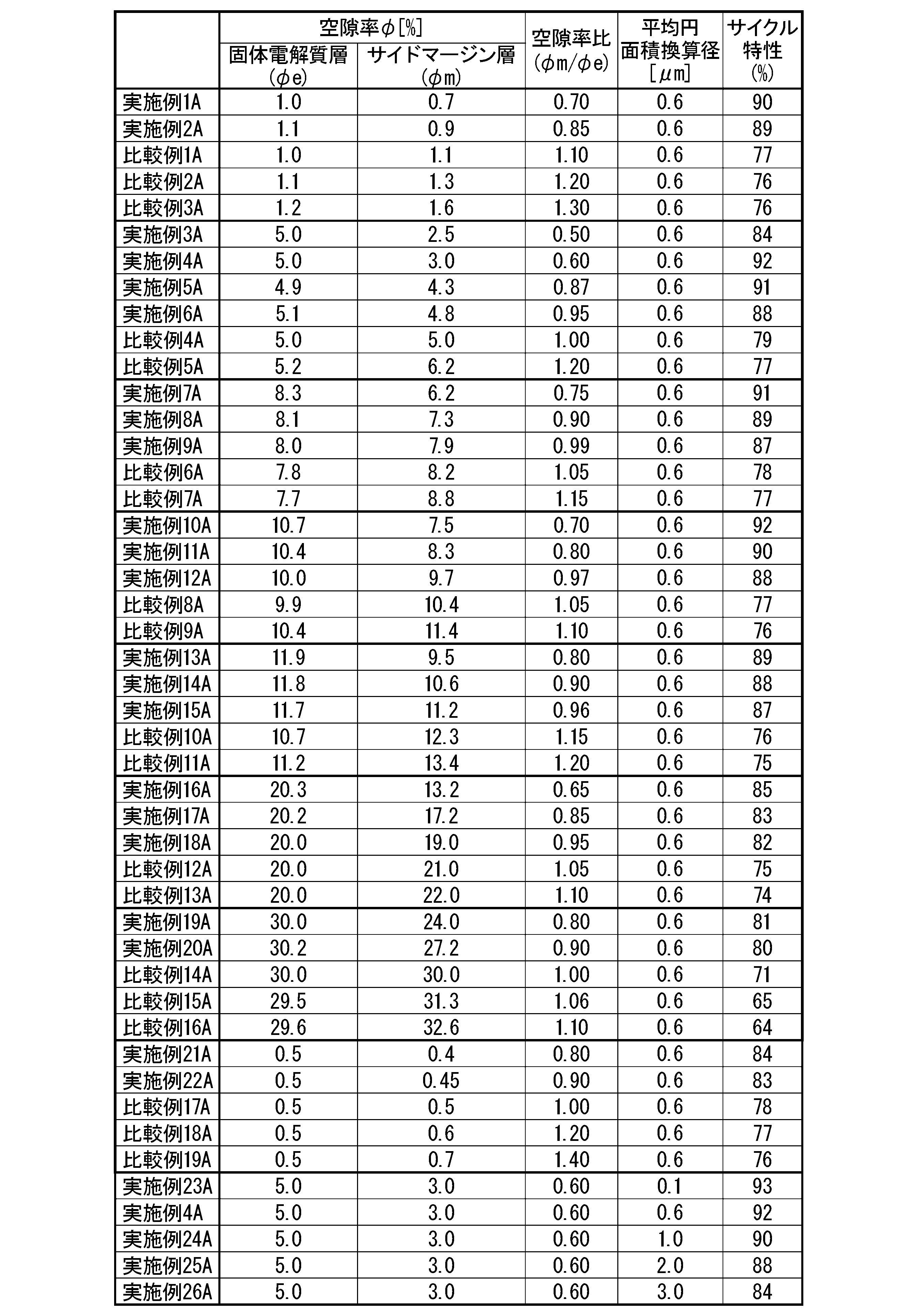
[実施例2A~実施例22A]
実施例2A~実施例22Aはそれぞれ、固体電解質層用ペースト及びサイドマージン用ペーストの作製において、空隙形成材であるナイロン微粒子の添加量を変えることにより、空隙率を調整した以外は、実施例1Aと同様にして全固体二次電池を作製した。
ナイロン微粒子の添加量は表2に示す。
実施例2A~実施例22Aはそれぞれ、固体電解質層用ペースト及びサイドマージン用ペーストの作製において、空隙形成材であるナイロン微粒子の添加量を変えることにより、空隙率を調整した以外は、実施例1Aと同様にして全固体二次電池を作製した。
ナイロン微粒子の添加量は表2に示す。
[比較例1A~比較例19A]
比較例1A~比較例19Aはそれぞれ、固体電解質層用ペースト及びサイドマージン用ペーストの作製において、空隙形成材であるナイロン微粒子の添加量を変えることにより、空隙率を調整した以外は、実施例1Aと同様にして全固体二次電池を作製した。
ナイロン微粒子の添加量は表2に示す。
比較例1A~比較例19Aはそれぞれ、固体電解質層用ペースト及びサイドマージン用ペーストの作製において、空隙形成材であるナイロン微粒子の添加量を変えることにより、空隙率を調整した以外は、実施例1Aと同様にして全固体二次電池を作製した。
ナイロン微粒子の添加量は表2に示す。
[実施例A23~実施例26A]
実施例23A~実施例26Aはそれぞれ、空隙形成材であるナイロン微粒子の粒子径を変えることにより、空隙のサイズを調整した以外は、実施例4Aと同様にして全固体二次電池を作製した。
ナイロン微粒子の粒子径はそれぞれ、実施例23A:0.2μm、実施例24A:2.0μm、実施例25A:3.0μm、実施例26A:5.0μmとした。
ナイロン微粒子の添加量は表2に示す。
実施例23A~実施例26Aはそれぞれ、空隙形成材であるナイロン微粒子の粒子径を変えることにより、空隙のサイズを調整した以外は、実施例4Aと同様にして全固体二次電池を作製した。
ナイロン微粒子の粒子径はそれぞれ、実施例23A:0.2μm、実施例24A:2.0μm、実施例25A:3.0μm、実施例26A:5.0μmとした。
ナイロン微粒子の添加量は表2に示す。
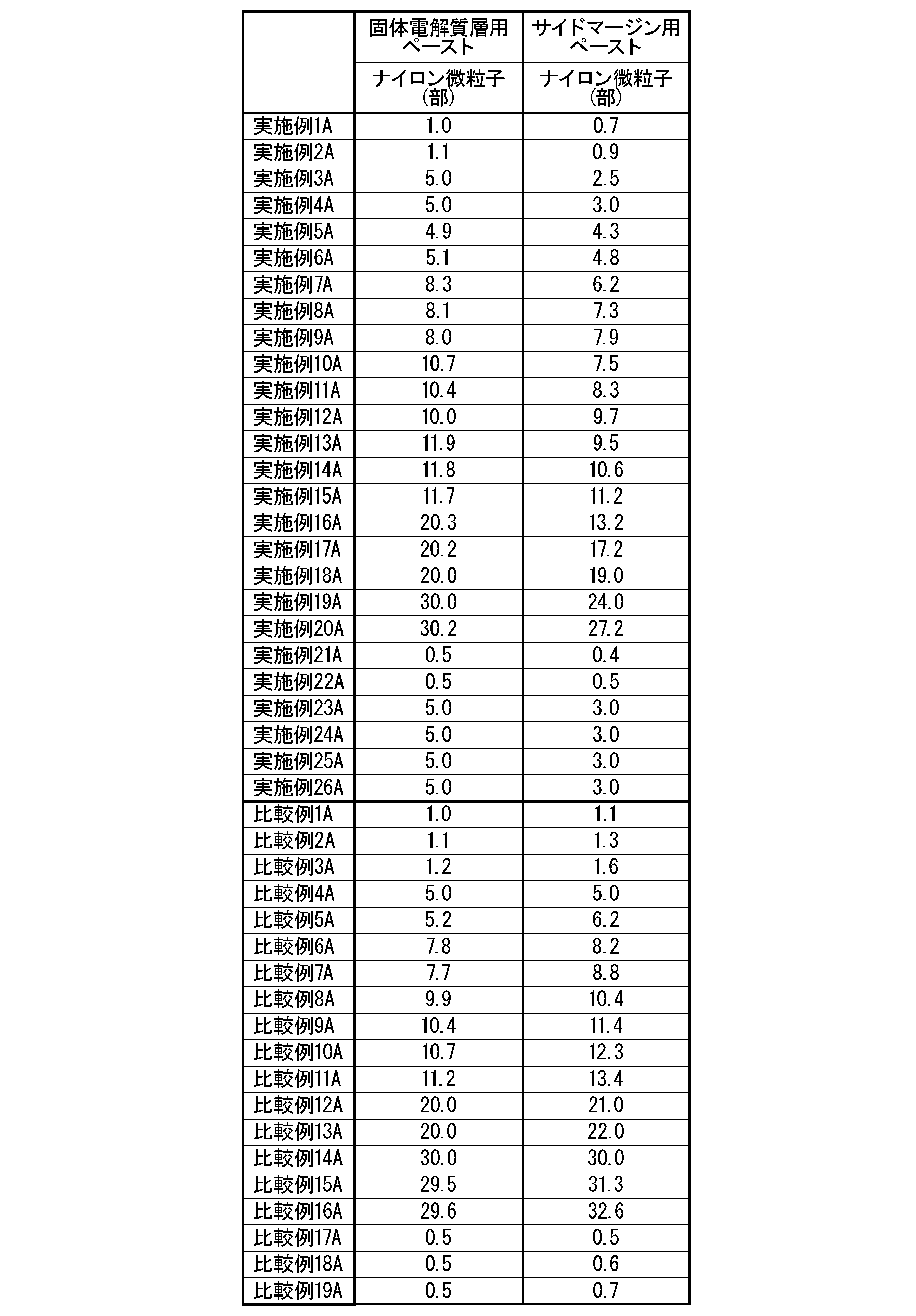
表1に基づくと、サイクル特性が90%以上のものは、実施例1A,4A,5A,7A,10A,11A,23A,24Aであり、これらの実施例の空隙率比(φm/φe)の範囲は、0.6≦(φm/φe)≦0.87、である。
さらに表1に基づき、サイクル特性が89%以上のものに広げると、実施例2A,8A,13Aが追加され、実施例2A,8A,13Aの追加後の空隙率比(φm/φe)の範囲は、0.6≦(φm/φe)≦0.90、である。
さらに表1に基づき、サイクル特性が88%以上のものに広げると、さらに実施例6A,12A,14Aが追加され、実施例6A,12A,14A,25Aの追加後の空隙率比(φm/φe)の範囲は、0.6≦(φm/φe)≦0.97、である。
さらに表1に基づき、サイクル特性が87%以上のものに広げると、さらに実施例9A,15Aが追加されます。実施例9A,15Aの追加後の空隙率比(φm/φe)の範囲は、0.6≦(φm/φe)≦0.99、である。
表1に基づくと、サイクル特性が90%以上のものは上述の通り、実施例1A,4A,5A,7A,10A,11A,23A,24Aであり、これらの固体電解質層の空隙率φeの範囲は、1.0≦φe≦10.7、である。
また、サイクル特性が89%以上のものに広げると上述の通り、実施例2A,8A,13Aが追加され、実施例2A,8A,13Aの追加後の固体電解質層の空隙率φeの範囲は、1.0≦φe≦11.9、である。
[実施例1-1B]
(固体電解質層用ペーストの作製)
Li1.3Al0.3Ti1.7(PO4)3の粉末100部に対して、溶媒としてエタノール100部、トルエン200部を加えてボールミルで湿式混合した。その後、バインダーとしてポリビニールブチラール系バインダー16部と、可塑剤としてフタル酸ベンジルブチル4.8部と、さらに空隙形成剤として平均粒径1μmのナイロン微粒子4.5部を投入し、混合して固体電解質層用ペーストとして調製した。
この固体電解質層用ペーストをドクターブレード法でPETフィルムを基材としてシート成形し、最外固体電解質層シート、及び、層間固体電解質層シートを得た。最外固体電解質層シート及び層間固体電解質層シートの厚さはいずれも15μmとした。
(固体電解質層用ペーストの作製)
Li1.3Al0.3Ti1.7(PO4)3の粉末100部に対して、溶媒としてエタノール100部、トルエン200部を加えてボールミルで湿式混合した。その後、バインダーとしてポリビニールブチラール系バインダー16部と、可塑剤としてフタル酸ベンジルブチル4.8部と、さらに空隙形成剤として平均粒径1μmのナイロン微粒子4.5部を投入し、混合して固体電解質層用ペーストとして調製した。
この固体電解質層用ペーストをドクターブレード法でPETフィルムを基材としてシート成形し、最外固体電解質層シート、及び、層間固体電解質層シートを得た。最外固体電解質層シート及び層間固体電解質層シートの厚さはいずれも15μmとした。
(サイドマージン用ペーストの作製)
Li1.3Al0.3Ti1.7(PO4)3の粉末100部に対して、バインダーとしてエチルセルロース15部と、溶媒としてジヒドロターピネオール65部とを加え、さらに空隙形成剤として平均粒径1μmのナイロン微粒子5.0部を投入し、混合・分散してサイドマージン層用ペーストとして調製した。
Li1.3Al0.3Ti1.7(PO4)3の粉末100部に対して、バインダーとしてエチルセルロース15部と、溶媒としてジヒドロターピネオール65部とを加え、さらに空隙形成剤として平均粒径1μmのナイロン微粒子5.0部を投入し、混合・分散してサイドマージン層用ペーストとして調製した。
(正極活物質層用ペーストおよび負極活物質層用ペーストの作製)
正極活物質層用ペースト及び負極活物質層用ペーストは、Li3V2(PO4)3の粉末100部に対して、バインダーとしてエチルセルロース15部と、溶媒としてジヒドロターピネオール65部とを加えて、混合・分散して正極活物質層用ペースト及び負極活物質層用ペーストを作製した。
正極活物質層用ペースト及び負極活物質層用ペーストは、Li3V2(PO4)3の粉末100部に対して、バインダーとしてエチルセルロース15部と、溶媒としてジヒドロターピネオール65部とを加えて、混合・分散して正極活物質層用ペースト及び負極活物質層用ペーストを作製した。
(正極集電体用ペーストおよび負極集電体用ペーストの作製)
正極集電体用ペーストおよび負極集電体用ペーストは、集電体としてCuとLi3V2(PO4)3とを体積比率で80:20となるように混合した後、この粉末100部に対し、バインダーとしてエチルセルロース10部と、溶媒としてジヒドロターピネオール50部を加えて混合・分散して正極集電体層用ペースト及び負極集電体層用ペーストを作製した。
正極集電体用ペーストおよび負極集電体用ペーストは、集電体としてCuとLi3V2(PO4)3とを体積比率で80:20となるように混合した後、この粉末100部に対し、バインダーとしてエチルセルロース10部と、溶媒としてジヒドロターピネオール50部を加えて混合・分散して正極集電体層用ペースト及び負極集電体層用ペーストを作製した。
(電極ユニットの作製)
正極ユニット及び負極ユニットを以下の通り作製した。
上記の層間固体電解質層シート上に、スクリーン印刷により厚さ5μmで正極活物質用ペーストを印刷した。次に、印刷した正極活物質用ペーストを80℃で5分間乾燥し、その上に、スクリーン印刷により厚さ5μmで集電体用ペーストを印刷した。次に、印刷した正極集電体用ペーストを80℃で5分間乾燥し、更にその上に、スクリーン印刷により厚さ5μmで正極活物質用ペーストを再度印刷し、乾燥した。そして、正極層以外の固体電解質層シートの領域に、サイドマージン層用ペーストをスクリーン印刷し、乾燥することで電極層と略同等の高さのサイドマージン層を形成した。次いでPETフィルムを剥離した。このようにして、層間固体電解質層の主面に、正極活物質層/正極集電体層/正極活物質層がこの順で積層された正極層とその外周に正極層の側面に接して配置する正極サイドマージン層とが形成された正極ユニットを得た。
同様の手順にて、固体電解質層の主面に、負極活物質層/負極集電体層/負極活物質層がこの順に積層された負極層とその外周に負極層の側面に接して配置する負極サイドマージン層とが形成された負極ユニットを得た。
正極ユニット及び負極ユニットを以下の通り作製した。
上記の層間固体電解質層シート上に、スクリーン印刷により厚さ5μmで正極活物質用ペーストを印刷した。次に、印刷した正極活物質用ペーストを80℃で5分間乾燥し、その上に、スクリーン印刷により厚さ5μmで集電体用ペーストを印刷した。次に、印刷した正極集電体用ペーストを80℃で5分間乾燥し、更にその上に、スクリーン印刷により厚さ5μmで正極活物質用ペーストを再度印刷し、乾燥した。そして、正極層以外の固体電解質層シートの領域に、サイドマージン層用ペーストをスクリーン印刷し、乾燥することで電極層と略同等の高さのサイドマージン層を形成した。次いでPETフィルムを剥離した。このようにして、層間固体電解質層の主面に、正極活物質層/正極集電体層/正極活物質層がこの順で積層された正極層とその外周に正極層の側面に接して配置する正極サイドマージン層とが形成された正極ユニットを得た。
同様の手順にて、固体電解質層の主面に、負極活物質層/負極集電体層/負極活物質層がこの順に積層された負極層とその外周に負極層の側面に接して配置する負極サイドマージン層とが形成された負極ユニットを得た。
(積層体の作製)
最外固体電解質層用の固体電解質層シートを5枚重ね、その上に電極ユニット50枚(正極ユニット25枚、負極ユニット25枚)を、層間固体電解質を介するようにして交互に積み重ねた。このとき、奇数枚目の電極ユニットの集電体ペースト層が一方の端面にのみ延出し、偶数枚目の電極ユニットの集電体ペースト層が反対側の端面にのみ延出するように、各ユニットをずらして積み重ねた。この積み重ねられたユニットの上に、最外固体電解質層用の固体電解質層シート6枚を積み重ねた。その後、これを熱圧着により成形した後、切断して積層チップを作製した。その後、積層チップを同時焼成して積層体を得た。同時焼成は、窒素雰囲気中で昇温速度200℃/時間で焼成温度840℃まで昇温して、その温度に2時間保持し、焼成後は自然冷却した。
最外固体電解質層用の固体電解質層シートを5枚重ね、その上に電極ユニット50枚(正極ユニット25枚、負極ユニット25枚)を、層間固体電解質を介するようにして交互に積み重ねた。このとき、奇数枚目の電極ユニットの集電体ペースト層が一方の端面にのみ延出し、偶数枚目の電極ユニットの集電体ペースト層が反対側の端面にのみ延出するように、各ユニットをずらして積み重ねた。この積み重ねられたユニットの上に、最外固体電解質層用の固体電解質層シート6枚を積み重ねた。その後、これを熱圧着により成形した後、切断して積層チップを作製した。その後、積層チップを同時焼成して積層体を得た。同時焼成は、窒素雰囲気中で昇温速度200℃/時間で焼成温度840℃まで昇温して、その温度に2時間保持し、焼成後は自然冷却した。
(全固体二次電池の作製、及び、評価)
公知の方法により、焼結した積層体(焼結体)に第1外部端子及び第2外部端子をつけて、全固体二次電池を作製した。
第1外部端子及び第2外部端子を対向するようにスプリングプローブで挟み込み、温度40℃、湿度93%の条件下で、充放電試験を行うことで全固体二次電池の初回放電容量及び100サイクル後の容量維持率を測定した。測定条件は、充電及び放電時の電流はいずれも20μA、充電時及び放電時の終止電圧をそれぞれ1.6V、0Vとした。その結果、サイクル特性は70%であった。なお、1回目の放電時の容量を初回放電容量とした。また容量維持率は、100サイクル目の放電容量を初回放電容量で割って求めた。
結果を表3に示す。
公知の方法により、焼結した積層体(焼結体)に第1外部端子及び第2外部端子をつけて、全固体二次電池を作製した。
第1外部端子及び第2外部端子を対向するようにスプリングプローブで挟み込み、温度40℃、湿度93%の条件下で、充放電試験を行うことで全固体二次電池の初回放電容量及び100サイクル後の容量維持率を測定した。測定条件は、充電及び放電時の電流はいずれも20μA、充電時及び放電時の終止電圧をそれぞれ1.6V、0Vとした。その結果、サイクル特性は70%であった。なお、1回目の放電時の容量を初回放電容量とした。また容量維持率は、100サイクル目の放電容量を初回放電容量で割って求めた。
結果を表3に示す。
また、焼結した積層体(焼結体)の固体電解質層及びサイドマージン層のそれぞれについて、上述した方法にて、空隙率を算出した。それぞれ、4.5%、5%であった。
結果を表3に示す。
結果を表3に示す。
また、焼結した積層体(焼結体)の固体電解質層及びサイドマージン層のそれぞれの断面のSEM像において、上述の方法にて、平均円面積換算径を算出したところ、0.5μmであった。
結果を表3に示す。
結果を表3に示す。
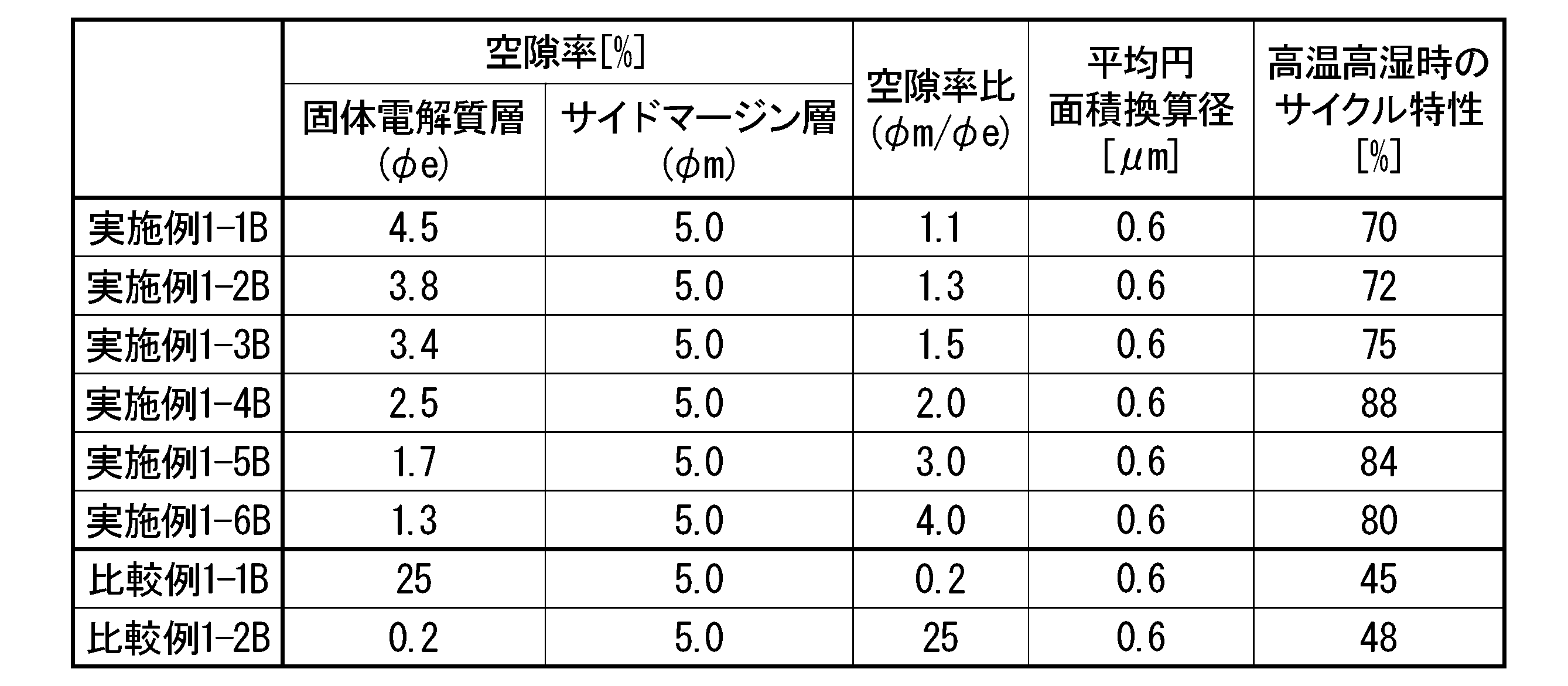
[実施例1-2B~実施例1-6B、比較例1-1B~比較例1-2B]
実施例1-2B~実施例1-6B、及び、比較例1-1B~比較例1-2Bはそれぞれ、固体電解質層用ペースト及びサイドマージン層用ペーストの作製において、平均粒径1μmのナイロン微粒子の添加量を変えることにより、空隙率を調整した以外は、実施例1-1Bと同様にして全固体二次電池を作製した。
ナイロン微粒子の添加量は表4に示す。
実施例1-2B~実施例1-6B、及び、比較例1-1B~比較例1-2Bはそれぞれ、固体電解質層用ペースト及びサイドマージン層用ペーストの作製において、平均粒径1μmのナイロン微粒子の添加量を変えることにより、空隙率を調整した以外は、実施例1-1Bと同様にして全固体二次電池を作製した。
ナイロン微粒子の添加量は表4に示す。

表3に示したように、高温高湿時(温度40℃、湿度93%)のサイクル特性は、比較例1-1B及び比較例1-2Bが50%未満であるのに対して、空隙率比(φm/φe)が1.1≦(φm/φe)≦4.0の範囲である実施例1-1B~実施例1-6Bでは70%以上であった。特に、空隙率比(φm/φe)が1.5≦(φm/φe)≦4.0の範囲である実施例1-3B~実施例1-6Bでは75%以上であり、さらに空隙率比(φm/φe)が2.0≦(φm/φe)≦4.0の範囲である実施例1-4B~実施例1-6Bでは80%以上であった。
[実施例2-1B~実施例2-20B、比較例2-1B~比較例2-8B]
実施例2-1B~実施例2-20B、及び、比較例2-1B~比較例2-8Bはそれぞれ、固体電解質層用ペースト及びサイドマージン層用ペーストの作製において、平均粒径1μmのナイロン微粒子の量を変えることにより、空隙率を調整した以外は、実施例1-1Bと同様にして全固体二次電池を作製した。
ナイロン微粒子の添加量は表5に示す。
全固体二次電池の評価結果を表6に示す。
実施例2-1B~実施例2-20B、及び、比較例2-1B~比較例2-8Bはそれぞれ、固体電解質層用ペースト及びサイドマージン層用ペーストの作製において、平均粒径1μmのナイロン微粒子の量を変えることにより、空隙率を調整した以外は、実施例1-1Bと同様にして全固体二次電池を作製した。
ナイロン微粒子の添加量は表5に示す。
全固体二次電池の評価結果を表6に示す。


表6に示したように、高温高湿時(温度40℃、湿度93%)のサイクル特性は、比較例2-1B~比較例2-8Bが50%未満であるのに対して、サイドマージン層の空隙率φmが0.1≦φm≦20の範囲である実施例2-1B~実施例2-20Bでは60%以上であった。特に、サイドマージン層の空隙率φmが1≦φm≦10の範囲である実施例2-5B~実施例2-12Bでは72%以上であった。
[実施例3-1B~実施例3-4B、比較例3-1B]
実施例3-1B~実施例3-4B、及び比較例3-1Bはそれぞれ、固体電解質層用ペースト及びサイドマージン層用ペーストの作製において、空隙形成剤として添加するナイロン微粒子の平均粒径をそれぞれ、0.2μm、2.0μm、0.1μm、3.0μm、8.0μmとして、平均円面積換算径を調整した以外は、実施例1-1Bと同様にして全固体二次電池を作製した。
ナイロン微粒子の添加量は表7に示す。
全固体二次電池の評価結果を表8に示す。
実施例3-1B~実施例3-4B、及び比較例3-1Bはそれぞれ、固体電解質層用ペースト及びサイドマージン層用ペーストの作製において、空隙形成剤として添加するナイロン微粒子の平均粒径をそれぞれ、0.2μm、2.0μm、0.1μm、3.0μm、8.0μmとして、平均円面積換算径を調整した以外は、実施例1-1Bと同様にして全固体二次電池を作製した。
ナイロン微粒子の添加量は表7に示す。
全固体二次電池の評価結果を表8に示す。

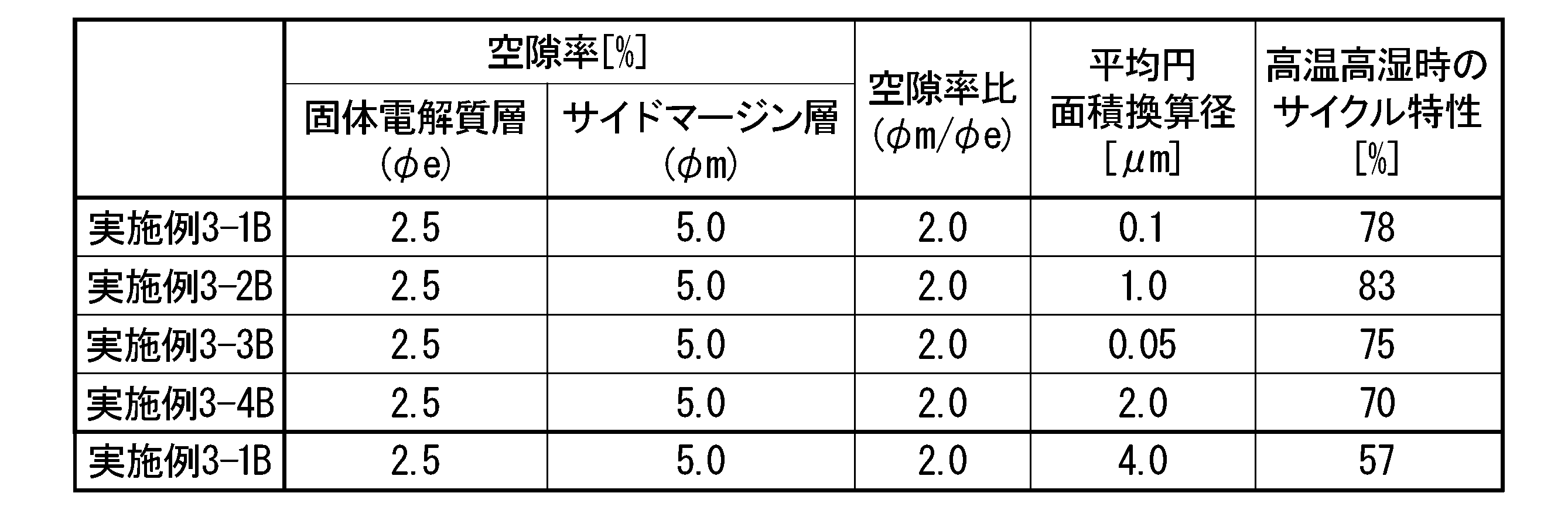
表8に示したように、高温高湿時(温度40℃、湿度93%)のサイクル特性は、比較例3-1Bが60%未満なのに対して、平均円面積換算径dが0.05≦d≦2.00μmである実施例3-1B~実施例3-4Bのいずれにおいても、高温高湿時(温度40℃、湿度93%)のサイクル特性は70%以上であった。特に、平均円面積換算径dが0.1≦d≦1μmである実施例3-1B~実施例3-2Bでは78%以上であった。
1 正極層
1A 正極集電体
1B 正極活物質層
2 負極層
2A 負極集電体
2B 負極活物質層
3 固体電解質層
3A 層間固体電解質層
3B 最外固体電解質層
41 正極サイドマージン層
42 負極サイドマージン層
6 第1外部端子
7 第2外部端子
20 積層体
100 全固体二次電池
1A 正極集電体
1B 正極活物質層
2 負極層
2A 負極集電体
2B 負極活物質層
3 固体電解質層
3A 層間固体電解質層
3B 最外固体電解質層
41 正極サイドマージン層
42 負極サイドマージン層
6 第1外部端子
7 第2外部端子
20 積層体
100 全固体二次電池
Claims (7)
- 正極集電体層と正極活物質層とを含む正極層と、
負極集電体層と負極活物質層とを含む負極層と、
固体電解質を含む固体電解質層と、
前記正極層および前記負極層のそれぞれに並んでその外周に配置する、サイドマージン層と、を有し、
前記正極層及びその外周に配置するサイドマージン層と、前記負極層及びその外周に配置するサイドマージン層とが、前記固体電解質層を介して交互に積層された積層体をなしており、
前記サイドマージン層の空隙率をφm、前記固体電解質層の空隙率をφeとしたとき、空隙率比(φm/φe)が以下の式(1)を満たす、全固体二次電池;
0.5≦(φm/φe)<1.0 ・・・・ (1) - 前記空隙率比(φm/φe)が以下の式(2)を満たす、請求項1に記載の全固体二次電池;
0.6≦(φm/φe)<1.0 ・・・・ (2) - 前記固体電解質層の空隙率φeが1.0%≦φe≦25.0%である、請求項1又は2のいずれかに記載の全固体二次電池。
- 前記固体電解質層と、前記サイドマージン層に含まれる空隙の平均円面積換算径dは、0.1≦d<2.0μmである、請求項1~3のいずれか一項に記載の全固体二次電池;
ここで、平均円面積換算径dは、SEM像中のn個の空隙の総面積がXとしたとき、以下の式(2)、
d={X/(n×π)}(1/2)×2 ・・・(3)
によって算出される。 - 正極集電体層と正極活物質層とを含む正極層と、
負極集電体層と負極活物質層とを含む負極層と、
固体電解質を含む固体電解質層と、
前記正極層および前記負極層のそれぞれに並んでその外周に配置する、サイドマージン層と、を有し、
前記正極層及びその外周に配置するサイドマージン層と、前記負極層及びその外周に配置するサイドマージン層とが、前記固体電解質層を介して交互に積層された積層体をなしており、
前記サイドマージン層の空隙率をφm、前記固体電解質層の空隙率をφeとしたとき、空隙率比(φm/φe)が以下の式(4)を満たす、全固体二次電池;
1.0<(φm/φe)≦4.0 ・・・・ (4) - 前記サイドマージン層の空隙率φmが0.1%≦φm≦20.0%である、請求項5に記載の全固体二次電池。
- 前記固体電解質層と、前記サイドマージン層に含まれる空隙の平均円面積換算径dは、0.05≦d≦2.00μmである、請求項5又は6のいずれかに記載の全固体二次電池;
ここで、平均円面積換算径dは、SEM像中のn個の空隙の総面積がXとしたとき、以下の式(3)、
d={X/(n×π)}(1/2)×2 ・・・(3)
によって算出される。
Priority Applications (4)
| Application Number | Priority Date | Filing Date | Title |
|---|---|---|---|
| DE112020001129.1T DE112020001129T5 (de) | 2019-03-08 | 2020-03-06 | Festkörperakkumulator |
| CN202080019000.XA CN113544891B (zh) | 2019-03-08 | 2020-03-06 | 全固体二次电池 |
| JP2021505048A JP7608324B2 (ja) | 2019-03-08 | 2020-03-06 | 全固体二次電池 |
| US17/431,549 US12002925B2 (en) | 2019-03-08 | 2020-03-06 | Solid-state secondary battery |
Applications Claiming Priority (4)
| Application Number | Priority Date | Filing Date | Title |
|---|---|---|---|
| JP2019043163 | 2019-03-08 | ||
| JP2019043162 | 2019-03-08 | ||
| JP2019-043162 | 2019-03-08 | ||
| JP2019-043163 | 2019-03-08 |
Publications (1)
| Publication Number | Publication Date |
|---|---|
| WO2020184476A1 true WO2020184476A1 (ja) | 2020-09-17 |
Family
ID=72427825
Family Applications (1)
| Application Number | Title | Priority Date | Filing Date |
|---|---|---|---|
| PCT/JP2020/009833 Ceased WO2020184476A1 (ja) | 2019-03-08 | 2020-03-06 | 全固体二次電池 |
Country Status (5)
| Country | Link |
|---|---|
| US (1) | US12002925B2 (ja) |
| JP (1) | JP7608324B2 (ja) |
| CN (1) | CN113544891B (ja) |
| DE (1) | DE112020001129T5 (ja) |
| WO (1) | WO2020184476A1 (ja) |
Cited By (7)
| Publication number | Priority date | Publication date | Assignee | Title |
|---|---|---|---|---|
| JPWO2022149336A1 (ja) * | 2021-01-08 | 2022-07-14 | ||
| US20220367846A1 (en) * | 2019-10-23 | 2022-11-17 | Tdk Corporation | All-solid-state battery |
| WO2023053759A1 (ja) * | 2021-09-30 | 2023-04-06 | 太陽誘電株式会社 | 全固体電池およびその製造方法 |
| JPWO2023063359A1 (ja) * | 2021-10-15 | 2023-04-20 | ||
| WO2023063360A1 (ja) * | 2021-10-15 | 2023-04-20 | 日本碍子株式会社 | リチウム二次電池 |
| WO2024204372A1 (ja) * | 2023-03-30 | 2024-10-03 | Tdk株式会社 | 全固体電池 |
| US12620630B2 (en) | 2019-10-23 | 2026-05-05 | Tdk Corporation | All-solid-state battery |
Families Citing this family (1)
| Publication number | Priority date | Publication date | Assignee | Title |
|---|---|---|---|---|
| KR102810351B1 (ko) * | 2022-11-09 | 2025-05-22 | 삼화콘덴서공업 주식회사 | Mlcb 및 그의 제조방법 |
Citations (3)
| Publication number | Priority date | Publication date | Assignee | Title |
|---|---|---|---|---|
| WO2013175993A1 (ja) * | 2012-05-24 | 2013-11-28 | 株式会社 村田製作所 | 全固体電池 |
| JP2014192041A (ja) * | 2013-03-27 | 2014-10-06 | Taiyo Yuden Co Ltd | 全固体二次電池 |
| JP2018166020A (ja) * | 2017-03-28 | 2018-10-25 | Fdk株式会社 | 全固体電池、および全固体電池の製造方法 |
Family Cites Families (20)
| Publication number | Priority date | Publication date | Assignee | Title |
|---|---|---|---|---|
| US20070259271A1 (en) | 2004-12-13 | 2007-11-08 | Tetsuo Nanno | Laminate Including Active Material Layer and Solid Electrolyte Layer, and All Solid Lithium Secondary Battery Using the Same |
| JP5165843B2 (ja) | 2004-12-13 | 2013-03-21 | パナソニック株式会社 | 活物質層と固体電解質層とを含む積層体およびこれを用いた全固体リチウム二次電池 |
| JP4352016B2 (ja) | 2005-03-18 | 2009-10-28 | 株式会社東芝 | 無機固体電解質電池及び無機固体電解質電池の製造方法 |
| JP2007294429A (ja) | 2006-03-30 | 2007-11-08 | Ohara Inc | リチウムイオン伝導性固体電解質およびその製造方法 |
| US20070231704A1 (en) | 2006-03-30 | 2007-10-04 | Ohara Inc. | Lithium ion conductive solid electrolyte and production process thereof |
| WO2007135790A1 (ja) * | 2006-05-23 | 2007-11-29 | Incorporated National University Iwate University | 全固体二次電池 |
| WO2008059987A1 (fr) | 2006-11-14 | 2008-05-22 | Ngk Insulators, Ltd. | Structure d'électrolyte solide pour un accumulateur entièrement électronique, accumulateur entièrement électronique et leurs procédés de production |
| JP5421151B2 (ja) * | 2010-02-25 | 2014-02-19 | 京セラ株式会社 | 全固体型リチウムイオン二次電池 |
| JP5677181B2 (ja) * | 2011-04-26 | 2015-02-25 | 京セラ株式会社 | 固体電解質およびそれを用いた二次電池 |
| FR2982082B1 (fr) * | 2011-11-02 | 2013-11-22 | Fabien Gaben | Procede de fabrication de batteries en couches minces entierement solides |
| FR3000616B1 (fr) * | 2012-12-31 | 2015-01-02 | I Ten | Procede de fabrication de batteries tout solide en structure multicouches |
| FR3002695B1 (fr) * | 2013-02-28 | 2021-04-02 | I Ten | Procede de fabrication d'une batterie monolithique entierement solide |
| JP6693226B2 (ja) * | 2016-03-30 | 2020-05-13 | Tdk株式会社 | 全固体型二次電池 |
| WO2018092434A1 (ja) * | 2016-11-17 | 2018-05-24 | 株式会社村田製作所 | 全固体電池、電子機器、電子カード、ウェアラブル機器および電動車両 |
| JP7009761B2 (ja) * | 2017-03-30 | 2022-01-26 | Tdk株式会社 | 全固体型二次電池 |
| JP6729796B2 (ja) * | 2017-04-04 | 2020-07-22 | 株式会社村田製作所 | 全固体電池、電子機器、電子カード、ウェアラブル機器および電動車両 |
| JP2019043162A (ja) | 2017-08-29 | 2019-03-22 | 本田技研工業株式会社 | 着脱ルーフの構造 |
| JP6953904B2 (ja) | 2017-08-29 | 2021-10-27 | いすゞ自動車株式会社 | 横置きリーフスプリング構造 |
| US11056716B2 (en) * | 2017-11-02 | 2021-07-06 | Taiyo Yuden Co., Ltd. | All solid battery |
| JP7167646B2 (ja) | 2018-11-09 | 2022-11-09 | 日本製鉄株式会社 | 溶鋼への合金添加方法 |
-
2020
- 2020-03-06 US US17/431,549 patent/US12002925B2/en active Active
- 2020-03-06 CN CN202080019000.XA patent/CN113544891B/zh active Active
- 2020-03-06 WO PCT/JP2020/009833 patent/WO2020184476A1/ja not_active Ceased
- 2020-03-06 JP JP2021505048A patent/JP7608324B2/ja active Active
- 2020-03-06 DE DE112020001129.1T patent/DE112020001129T5/de active Pending
Patent Citations (3)
| Publication number | Priority date | Publication date | Assignee | Title |
|---|---|---|---|---|
| WO2013175993A1 (ja) * | 2012-05-24 | 2013-11-28 | 株式会社 村田製作所 | 全固体電池 |
| JP2014192041A (ja) * | 2013-03-27 | 2014-10-06 | Taiyo Yuden Co Ltd | 全固体二次電池 |
| JP2018166020A (ja) * | 2017-03-28 | 2018-10-25 | Fdk株式会社 | 全固体電池、および全固体電池の製造方法 |
Cited By (13)
| Publication number | Priority date | Publication date | Assignee | Title |
|---|---|---|---|---|
| US20220367846A1 (en) * | 2019-10-23 | 2022-11-17 | Tdk Corporation | All-solid-state battery |
| US12626950B2 (en) * | 2019-10-23 | 2026-05-12 | Tdk Corporation | All-solid-state battery |
| US12620630B2 (en) | 2019-10-23 | 2026-05-05 | Tdk Corporation | All-solid-state battery |
| JP7804876B2 (ja) | 2021-01-08 | 2026-01-23 | パナソニックIpマネジメント株式会社 | 電池及び電池の製造方法 |
| JPWO2022149336A1 (ja) * | 2021-01-08 | 2022-07-14 | ||
| WO2023053759A1 (ja) * | 2021-09-30 | 2023-04-06 | 太陽誘電株式会社 | 全固体電池およびその製造方法 |
| JP2023050822A (ja) * | 2021-09-30 | 2023-04-11 | 太陽誘電株式会社 | 全固体電池およびその製造方法 |
| WO2023063360A1 (ja) * | 2021-10-15 | 2023-04-20 | 日本碍子株式会社 | リチウム二次電池 |
| JP7751651B2 (ja) | 2021-10-15 | 2025-10-08 | 日本碍子株式会社 | リチウム二次電池 |
| JPWO2023063360A1 (ja) * | 2021-10-15 | 2023-04-20 | ||
| WO2023063359A1 (ja) * | 2021-10-15 | 2023-04-20 | 日本碍子株式会社 | リチウム二次電池 |
| JPWO2023063359A1 (ja) * | 2021-10-15 | 2023-04-20 | ||
| WO2024204372A1 (ja) * | 2023-03-30 | 2024-10-03 | Tdk株式会社 | 全固体電池 |
Also Published As
| Publication number | Publication date |
|---|---|
| CN113544891A (zh) | 2021-10-22 |
| US20220140386A1 (en) | 2022-05-05 |
| JPWO2020184476A1 (ja) | 2020-09-17 |
| US12002925B2 (en) | 2024-06-04 |
| DE112020001129T5 (de) | 2021-12-09 |
| CN113544891B (zh) | 2023-11-28 |
| JP7608324B2 (ja) | 2025-01-06 |
Similar Documents
| Publication | Publication Date | Title |
|---|---|---|
| CN101663788B (zh) | 锂离子二次电池以及其制造方法 | |
| JP7608324B2 (ja) | 全固体二次電池 | |
| CN102246335B (zh) | 锂离子二次电池及其制造方法 | |
| JP6927289B2 (ja) | 全固体二次電池 | |
| CN113228375B (zh) | 全固体电池 | |
| JP6881465B2 (ja) | 全固体リチウムイオン二次電池 | |
| JP6919657B2 (ja) | 全固体リチウムイオン二次電池 | |
| JP6623542B2 (ja) | リチウムイオン二次電池 | |
| JP7031596B2 (ja) | 全固体リチウムイオン二次電池 | |
| WO2020105662A1 (ja) | 全固体電池 | |
| WO2021090774A1 (ja) | 全固体電池 | |
| WO2018062079A1 (ja) | 活物質及び全固体リチウムイオン二次電池 | |
| CN113169372A (zh) | 全固体二次电池 | |
| JPWO2018181575A1 (ja) | 全固体リチウムイオン二次電池 | |
| CN113273015A (zh) | 全固体电池 | |
| JP7509748B2 (ja) | 全固体二次電池 | |
| JP7812914B2 (ja) | 全固体二次電池 | |
| CN114982031B (zh) | 层叠型全固体电池 | |
| JP7812909B2 (ja) | 全固体電池 | |
| JP7850872B2 (ja) | 全固体電池 | |
| WO2024135262A1 (ja) | 全固体電池 | |
| JP2023168868A (ja) | 全固体二次電池 | |
| WO2024135831A1 (ja) | 全固体電池及び電子機器 | |
| WO2023188466A1 (ja) | 全固体二次電池 |
Legal Events
| Date | Code | Title | Description |
|---|---|---|---|
| 121 | Ep: the epo has been informed by wipo that ep was designated in this application |
Ref document number: 20769358 Country of ref document: EP Kind code of ref document: A1 |
|
| ENP | Entry into the national phase |
Ref document number: 2021505048 Country of ref document: JP Kind code of ref document: A |
|
| 122 | Ep: pct application non-entry in european phase |
Ref document number: 20769358 Country of ref document: EP Kind code of ref document: A1 |