WO2020184218A1 - 打込機 - Google Patents
打込機 Download PDFInfo
- Publication number
- WO2020184218A1 WO2020184218A1 PCT/JP2020/008297 JP2020008297W WO2020184218A1 WO 2020184218 A1 WO2020184218 A1 WO 2020184218A1 JP 2020008297 W JP2020008297 W JP 2020008297W WO 2020184218 A1 WO2020184218 A1 WO 2020184218A1
- Authority
- WO
- WIPO (PCT)
- Prior art keywords
- trigger
- operating
- operates
- state
- striking
- Prior art date
- Legal status (The legal status is an assumption and is not a legal conclusion. Google has not performed a legal analysis and makes no representation as to the accuracy of the status listed.)
- Ceased
Links
Images




Classifications
-
- B—PERFORMING OPERATIONS; TRANSPORTING
- B25—HAND TOOLS; PORTABLE POWER-DRIVEN TOOLS; MANIPULATORS
- B25C—HAND-HELD NAILING OR STAPLING TOOLS; MANUALLY OPERATED PORTABLE STAPLING TOOLS
- B25C7/00—Accessories for nailing or stapling tools, e.g. supports
Definitions
- the present invention relates to a driving machine having a striking portion for striking a fastener and a driving portion for operating the striking portion.
- Patent Document 1 describes an example of a driving machine having a striking portion for striking a fastener and a driving portion for operating the striking portion.
- the driving machine described in Patent Document 1 includes a housing, a cylinder, a valve, a pressure chamber as a drive unit, an exhaust valve chamber, an auxiliary pressure chamber, an accumulator chamber, a striking unit, an exhaust valve, a trigger as an operating member, and a push lever. It has a return air chamber, an injection part, and a magazine.
- a mechanism for transmitting the operation of the trigger and the push lever to the valve is provided.
- the magazine houses the fasteners, which are supplied to the injection section.
- the valve When the user releases the operating force on the trigger and push lever, the valve retains its initial state.
- the valve in the initial state connects the accumulator chamber and the auxiliary pressure chamber, and also connects the accumulator chamber and the exhaust valve chamber. Therefore, the cylinder is pressed against the valve seat and stops, and the cylinder shuts off the accumulator chamber and the pressure chamber. Further, the exhaust valve connects the outside of the housing to the pressure chamber. Therefore, the striking portion stops at top dead center in contact with the valve seat.
- the valve switches from the initial state to the operating state.
- the operating valve shuts off the accumulator chamber and the auxiliary pressure chamber, and also shuts off the accumulator chamber and the exhaust valve chamber. Therefore, the cylinder is pressed against the valve seat and stops, and the cylinder connects the accumulator chamber and the pressure chamber.
- the exhaust valve also shuts off the outside of the housing from the pressure chamber. Then, the compressed air in the accumulator chamber is supplied to the pressure chamber, the striking portion operates from the top dead center to the bottom dead center, and the striking portion strikes the fastener and reaches the bottom dead center. While the striking part is operating from the top dead center to the bottom dead center, the air pressure in the lower chamber of the piston rises.
- the valve When the user separates the push lever from the mating material and releases the operating force on the trigger, the valve returns from the operating state to the initial state.
- the striking part operates by the pressure of the lower chamber of the piston, and the striking part stops at top dead center.
- the inventor of the present application has recognized that when switching the valve from the operating state to the initial state, it is necessary to perform an operation of releasing the operating force applied to the operating member, which reduces the operability.
- An object of the present invention is to provide a driving machine capable of improving the operability of an operating member.
- the driving machine of one embodiment is provided in a housing and operates in an additional direction when the user applies an operating force, and operates in a release direction opposite to the additional direction when the user releases the operating force.
- a driving unit including a driving unit that operates the striking unit in the first direction and a contact member that is operably provided with respect to the housing and that can contact or separate the mating material into which the fastener is driven.
- the machine is provided with an auxiliary mechanism capable of switching between application and non-addition of urging force in the release direction to the operation member, and the auxiliary mechanism is said when the operation member operates in the addition direction. It has a first state in which the urging force in the release direction is not applied to the operating member, and a second state in which the urging force in the release direction is applied when the operating member operates in the release direction.
- the driving machine of one embodiment can improve the operability of the operating member.
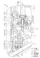
- FIG. 3 is a cross-sectional view of the return mechanism shown in FIG. 3 in a state where the movable member is in the operating position.
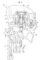
- FIG. 3 is a cross-sectional view of the return mechanism shown in FIG. 3 in a state in which an operating force is applied to the trigger.
- FIG. 1 is a cross-sectional view showing a state in which a movable member is stopped at an initial position.
- FIG. 6 is a cross-sectional view of the return mechanism shown in FIG. 6 in a state where the movable member is in the operating position.
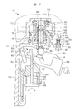
- FIG. 3 is a cross-sectional view of the return mechanism shown in FIG. 3 in a state in which an operating force is applied to the trigger. It is the whole sectional view showing Embodiment 2 of a driving tool.
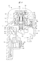
- 9 is a cross-sectional view showing a state in which a movable member is stopped at an initial position, which is a return mechanism provided in the driving machine of FIG.
- FIG. 9 is a cross-sectional view of the return mechanism shown in FIG. 9 in a state where the movable member is in the operating position.
- FIG. 9 is a cross-sectional view of the return mechanism shown in FIG. 9 in a state where an operating force is applied to the trigger.
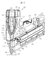
- the driving machine 10 includes a housing 11, a cylinder 12, a striking portion 13, an injection portion 15, a trigger valve 51, a trigger 14, and a push lever 16. Further, the magazine 17 is attached to the driving machine 10.
- the housing 11 has a tubular body portion 18, a head cover 21 fixed to the body portion 18, and a handle 19 connected to the body portion 18. The handle 19 projects from the outer surface of the body portion 18.
- the accumulator chamber 20 is formed over the inside of the handle 19, the inside of the body portion 18, and the inside of the head cover 21.
- the air hose is connected to the handle 19. Compressed air as a compressed gas is supplied into the accumulator chamber 20 via an air hose.
- the cylinder 12 is provided in the body portion 18.
- the head valve 31 is provided in the head cover 21.
- the head valve 31 is movable in the direction of the center line A1 of the cylinder 12.
- the control chamber 27 is formed between the head cover 21 and the head valve 31.
- the urging member 28 is provided in the control chamber 27.
- the urging member 28 is, for example, a metal compression coil spring.
- the urging member 28 urges the head valve 31 in the direction closer to the cylinder 12 in the center line A1 direction.
- the head valve 31 is constantly urged away from the cylinder 12 by the pressure of the accumulator chamber 20.
- the stopper 29 is provided in the head cover 21.
- the stopper 29 is made of synthetic rubber as an example.
- the head cover 21 has an exhaust passage 24. The exhaust passage 24 is connected to the outer B1 of the housing 11.
- the cylinder 12 is positioned and fixed with respect to the body portion 18 in the direction along the center line A1.
- a valve seat 32 is attached to the end of the cylinder 12 at a position closest to the head valve 31 in the direction along the center line A1.
- the valve seat 32 is annular and is made of synthetic rubber.
- the striking portion 13 has a piston 34 and a driver blade 35 fixed to the piston 34.
- the piston 34 is arranged in the cylinder 12, and the striking portion 13 can move linearly along the center line A1. That is, the striking portion 13 can reciprocate along the first direction D1 and the second direction D2.
- the first direction D1 can be defined as descending in FIGS. 1 and 2, and the second direction D2 can be defined as ascending.
- the first direction D1 and the second direction D2 are opposite directions.
- a seal member 99 is attached to the outer peripheral surface of the piston 34.
- the piston upper chamber 36 is formed between the stopper 29 and the piston 34.
- the injection portion 15 is fixed to the body portion 18 at an end portion opposite to the portion where the head cover 21 is provided in the direction along the center line A1.
- the bumper 37 is provided in the cylinder 12.
- the bumper 37 is arranged in the cylinder 12 at a position closest to the injection portion 15 in the center line A1 direction.
- the bumper 37 is made of synthetic rubber or silicon rubber.
- the bumper 37 has a shaft hole 38, and the driver blade 35 can move in the shaft hole 38 in the direction of the center line A1.
- a piston lower chamber 39 is formed between the piston 34 and the bumper 37.
- the lower chamber of the piston is connected to the shaft hole.
- the seal member 99 airtightly shuts off the piston lower chamber 39 and the piston upper chamber 36.
- An annular partition wall 40 is provided in the body portion 18.
- the partition wall 40 is arranged so as to surround the outer periphery of the cylinder 12, and positions the cylinder 12 with respect to the housing in a direction intersecting the center line A1.
- the return air chamber 43 is formed between the outer surface of the cylinder 12 and the body portion 18.
- the partition wall 40 separates the accumulator chamber 20 and the return air chamber 43.
- Passages 41 and 42 that penetrate the cylinder 12 in the radial direction are provided.
- the passage 42 is arranged between the passage 41 and the injection portion 15 in the direction of the center line A1.
- the passage 41 connects the piston lower chamber 39 and the return air chamber 43.
- the check valve 44 shown in FIG. 3 is attached to the outer surface of the cylinder 12.
- the check valve 44 opens the passage 41 by the air pressure in the cylinder 12.
- the check valve 44 closes the passage 41 with the air pressure of the return air chamber 43.
- the passage 42 always connects the return air chamber 43 and the piston lower chamber 39. Air is present in the lower piston chamber 39 and the return air chamber 43.
- a trigger valve 51 is provided at a connection point between the body portion 18 and the handle 19.
- the trigger valve 51 has a plunger 52, a body 53, a valve body 55, and a spring 69, as shown in FIGS. 3, 4, and 5.
- Both the body 53 and the valve body 55 have a tubular shape, and the body 53 and the valve body 55 are both arranged concentrically with the center line A2 as the center.
- FIG. 1 shows an example in which the center line A1 and the center line A2 are parallel to each other.
- the body 53 is fixed to the housing 11.
- the valve body 55 can operate in the body 53 in the direction along the center line A2.
- the body 53 has a passage 56, an exhaust passage 61, and a shaft hole 62.
- the passage 56 is connected to the control room 27 via the passage 57.
- the passage 57 is provided in the housing 11.
- the handle 19 has a passage 58, and the passage 58 connects the accumulator chamber 20 and the inside of the body 53.
- the exhaust passage 61 is connected to the outer B1 of the housing 11.
- the plunger 52 is arranged in the shaft hole 62 and the valve body 55.
- the plunger 52 can move in the direction along the center line A2.
- the end portion in the direction along the center line A2 is arranged on the outer B1 of the housing 11.
- the spring 69 is made of metal as an example.
- the spring 69 urges the plunger 52 in a direction along the center line A2 so as to approach the trigger 14.
- the spring 69 urges the valve body 55 in a direction along the center line A2 so as to approach the passage 58.
- the injection portion 15 shown in FIG. 1 is made of metal or non-ferrous metal as an example.
- the injection portion 15 has a tubular portion 70 and a flange 71 connected to the outer peripheral surface of the tubular portion 70.
- the flange 71 is fixed to the body portion 18.
- the tubular portion 70 projects from the flange 71 in the direction along the center line A1, and the tubular portion 70 has an injection path 72.
- the injection path 72 is a hole or space, and the center line A1 is located in the injection path 72.
- the driver blade 35 can operate in the injection path 72 in the direction along the center line A1.
- the magazine 17 is attached to the injection portion 15.
- the magazine 17 accommodates the nail 73.
- the magazine 17 has a feeder 74, and the feeder 74 sends the nail 73 in the magazine 17 to the injection path 72.
- the push lever 16 is attached to the injection portion 15.
- the push lever 16 can operate in the direction along the center line A1 with respect to the injection portion 15.
- the guide member 63 and the holder 64 are attached to the outer surface of the housing 11, for example, the body portion 18.
- the guide member 63 and the holder 64 are arranged between the trigger valve 51 and the injection portion 15 in the direction along the center line A2.
- the holder 64 has a tubular shape, and the holder 64 movably supports the transmission member 65.
- the transmission member 65 can move in the direction along the center line A3 together with the push lever 16.
- the center line A3 is parallel to the center line A2.
- the guide member 63 movably supports the transmission member 67.
- the moving direction of the transmission member 67 and the transmission member 65 is a direction along the center line A3.
- the transmission member 67 has a shaft shape, and a plate 68 is provided at an end portion of the transmission member 67.
- a spring 45 is arranged between the guide member 63 and the plate 68. The spring 45 urges the transmission member 67 in a direction that separates it from the trigger valve 51.
- the transmission member 67 stops at the initial position when the plate 68 is pressed against the holder 64.
- the spring 45 is made of metal as an example.
- the guide member 63 moves the transmission member 67 in the direction along the center line A3.
- the transmission member 67 has a protrusion 80.
- the protrusion 80 is provided at a position located between the guide member 63 and the trigger valve 51 in the direction along the center line A3 of the transmission member 67.
- the protrusion 80 projects from the transmission member 67 in a direction intersecting
- the trigger 14 is arranged on the outer B1 of the housing 11.
- the trigger 14 is arranged between the trigger valve 51 and the guide member 63 in the direction along the center line A2.
- the trigger 14 is attached to the body portion 18 via the support shaft 81.
- the trigger 14 is rotatable about the support shaft 81.
- the direction in which the trigger 14 operates counterclockwise in FIG. 3 can be defined as the additional direction E1.
- the direction in which the trigger 14 operates clockwise in FIG. 3 can be defined as the release direction E2.
- the addition direction E1 is a direction in which the trigger 14 approaches the trigger valve 51.
- the release direction E2 is a direction in which the trigger 14 is separated from the trigger valve 51.
- the addition direction E1 and the release direction E2 are opposite directions.
- the trigger 14 has an arm 82 and a boss portion 83.
- the protrusion 80, the arm 82, and the spring 45 form an auxiliary mechanism 85.
- a spring 84 is provided between the boss portion 83 and the body 53.
- the trigger 14 is urged by the spring 84 clockwise around the support shaft 81 in FIG.
- the spring 84 is, for example, a metal spring.
- the protrusion 80 of the transmission member 67 is located between the arm 82 and the boss 83 in a direction intersecting the center line A3.
- the mating material W1 includes wood, gypsum board, concrete and the like.
- the trigger valve 51 holds the initial state shown in FIG.
- the plunger 52 is stopped at the initial position pressed against the body 53 by the urging force of the spring 69.
- the valve body 55 is stopped at the initial position pressed against the body 53 by the spring 69.
- the valve body 55 connects the accumulator chamber 20 and the passage 56, and shuts off the passage 56 and the exhaust passage 61.
- the compressed air in the accumulator chamber 20 is supplied to the control chamber 27, and the head valve 31 is pressed against the valve seat 32 and stopped as shown in FIG.
- the head valve 31 shuts off the accumulator chamber 20 and the piston upper chamber 36, and connects the piston upper chamber 36 and the exhaust passage 24.
- the pressure of the piston upper chamber 36 is the same as the atmospheric pressure.
- the striking portion 13 is stopped at the position where the piston 34 is closest to the stopper 29, that is, at the top dead center.
- the striking portion 13 is stopped at the top dead center due to the frictional force between the seal member 99 and the cylinder 12 or the engaging force between the seal member 99 and the cylinder 12.
- the transmission member 67 operates in the third direction D3, which approaches the trigger valve 51 against the force of the spring 45, and the transmission member 67 stops at the operating position shown in FIG.
- the third direction D3 is a direction along the center line A3.
- the trigger 14 When the user presses a finger against the trigger 14 to apply an operating force and rotates the trigger 14 counterclockwise against the force of the spring 84, the trigger 14 is the body 53 or the handle as shown in FIG. It stops at the operating position in contact with 19. The operating force of the trigger 14 is transmitted to the plunger 52 via the boss portion 83. Therefore, the plunger 52 operates from the initial position toward the passage 58 against the force of the spring 69, and the plunger 52 stops at the operating position. Further, in the process in which the trigger 14 operates in the addition direction E1 from the initial position, the protrusion 80 is separated from the arm 82. Therefore, the protrusion 80 does not prevent the trigger 14 from operating in the addition direction E1.
- the trigger valve 51 switches from the initial state to the operating state.
- the valve body 55 operates in a direction away from the passage 58 by the pressure of the accumulator chamber 20, and the valve body 55 stops at the operating position pressed against the body 53. To do.
- the valve body 55 stopped at the operating position shuts off the accumulator chamber 20 and the passage 56, and connects the passage 56 to the exhaust passage 61. Therefore, the compressed air in the control chamber 27 is discharged to the outside B1 through the passage 57, the passage 56, and the exhaust passage 60, and the pressure in the control chamber 27 becomes the same as the atmospheric pressure.
- the head valve 31 When the pressure in the control chamber 27 becomes the same as the atmospheric pressure, the head valve 31 operates against the urging force of the urging member 28 by the pressure of the accumulator chamber 20 and stops at the operating position in contact with the stopper 29. To do.
- the head valve 31 stopped at the operating position connects the accumulator chamber 20 and the piston upper chamber 36, and shuts off the piston upper chamber 36 and the exhaust passage 24.
- the pressure of the piston upper chamber 36 rises, the striking portion 13 operates from the top dead center to the bottom dead center, and the driver blade 35 strikes the nail 73 in the injection path 72.
- the hit nail 73 is driven into the mating material W1. While the striking portion 13 is operating from the top dead center to the bottom dead center, the pressures in the piston lower chamber 39 and the return air chamber 43 increase. Further, the check valve 44 opens, and the air in the piston upper chamber 36 returns through the passage 41 and flows into the air chamber 43.
- the piston 34 collides with the bumper 37, and the bumper 37 absorbs a part of the kinetic energy of the striking portion 13.
- the position of the striking portion 13 at the time when the piston 34 collides with the bumper 37 is the bottom dead center.
- the check valve 44 closes the passage 41.
- the piston 34 shuts off the piston lower chamber 39 and the shaft hole 38.
- the striking portion 13 separates the nail 73 from the mating material W1 by the reaction of being driven into the mating material W1.
- the transmission member 67 operates in the fourth direction D4 in FIG. 5 by the force of the spring 45.
- the fourth direction D4 is a direction along the center line A3.
- the transmission member 67 and the push lever 16 stop at the initial positions. While the transmission member 67 is operating in a direction away from the trigger valve 51 along the center line A3, the protrusion 80 is pressed against the arm 82. A part of the operating force of the transmission member 67 is converted into a force for operating the trigger 14 clockwise in FIG. 5, and the trigger 14 returns to the initial position shown in FIG. 3 and stops.
- the trigger 14 can be returned from the operating position of FIG. 5 to the initial position of FIG. 3 by utilizing the force of the spring 45, which is a power source for returning the transmission member 67 and the push lever 16 from the operating position to the initial position. Therefore, the user does not have to intentionally perform the operation of releasing the operating force applied to the trigger 14 or separating the finger from the trigger 14. Therefore, the operability for the trigger 14 is improved.
- the spring 45 serves as a return mechanism for operating the trigger 14 from the operating position to the initial position.
- the urging force of the spring 45 is not transmitted in the direction in which the trigger 14 is operated clockwise in FIG. Therefore, it is possible to suppress an increase in the operating force required to operate the trigger 14 from the initial position to the operating position.
- the operating force required to operate the trigger 14 from the initial position to the operating position is determined according to the urging force of the springs 45 and 84.
- the protrusion 80 is separated from the arm 82. Therefore, in the stroke in which the trigger 14 operates in the addition direction E1 from the initial position to the operation position, the urging force of the spring 45 is not applied in the release direction E2 of the trigger 14.
- the trigger valve 51 switches from the operating state to the initial state. .. Therefore, the striking portion 13 operates in the first direction D1 under the pressure of the piston lower chamber 39, and the striking portion 13 stops at the top dead center. Further, when the piston 34 is separated from the bumper 37, the air in the piston lower chamber 39 is discharged from the shaft hole 38 to the outside B1. After the striking portion 13 reaches the top dead center, the pressures of the piston lower chamber 39 and the return air chamber 43 become substantially the same as the atmospheric pressure.
- a valve 90 is provided on the housing 11, the handle 19 as an example.
- the trigger valve 51 is located between the valve 90 and the body 18 in the direction in which the handle 19 protrudes from the body 18, that is, in the direction intersecting the center line A2.
- the valve 90 has a support hole 91, a plunger 92 and an urging member 93.
- the support hole 91 connects the accumulator chamber 20 and the external B1.
- the plunger 92 is arranged in the support hole 91, and the plunger 92 can move in the direction along the center line A4 with respect to the handle 19.
- the center line A4 is parallel to the center line A2.
- An annular seal member 94 is attached to the outer peripheral surface of the plunger 92.
- a part of the plunger 92 in the length direction is arranged on the outer B1, and a plate 95 is provided at a place where the plunger 92 is arranged on the outer B1.
- the urging member 93 is, for example, a metal spring, and the urging member 93 urges the plunger 92 toward the trigger 14.
- the trigger 14 has a contact portion 96.
- the boss portion 83 is located between the contact portion 96 and the support shaft 81 in the length direction of the trigger 14.
- the plate 95 is arranged in the working region of the contact portion 96.
- the contact portion 96 is separated from the plate 95.
- the plunger 92 is stopped at the initial position in a state where the seal member 94 is pressed against the inner surface of the support hole 91.
- the seal member 94 airtightly shields the accumulator chamber 20 from the external B1.
- the transmission member 67 moves from the initial position to the operating position as shown in FIG. 7 and stops.
- the contact portion 96 is separated from the plate 95.
- the contact portion 96 presses against the plate 95. Be done.
- the plunger 92 operates in a direction approaching the accumulator chamber 20 against the force of the urging member 93.
- the plunger 92 stops at the operating position.
- the seal member 94 is separated from the inner surface of the support hole 91, and the support hole 91 connects the accumulator chamber 20 and the outer B1. The compressed air in the accumulator chamber 20 is blown to the trigger 14 through the support hole 91.
- the trigger 14 When the user releases the operating force on the trigger 14, the trigger 14 is urged in the release direction E2 by the kinetic energy of the compressed air blown from the support hole 91 to the trigger 14. Therefore, the operability when the trigger 14 is returned from the operating position to the initial position is improved.
- the plunger 92 operates by the urging force of the urging member 93, the seal member 94 is pressed against the inner surface of the support hole 91, and the plunger 92 stops at the initial position. .. That is, the valve 90 returns to the initial state.
- the valve 90 serves as a return mechanism for operating the trigger 14 from the operating position to the initial position.
- the valve 90 closes the support hole 91, and the compressed air in the accumulator chamber 20 is not exhausted from the support hole 91 to the outside B1. That is, in FIG. 7, no force is generated in the direction in which the trigger 14 is operated clockwise. Therefore, it is possible to suppress an increase in the operating force required to operate the trigger 14 from the initial position to the operating position.
- the contact portion 96 is separated from the plate 95 in the process of operating the trigger 14 in the addition direction E1, the compressed air in the accumulator chamber 20 is not discharged from the support hole 91 to the outside B1. That is, in the process in which the trigger 14 operates in the addition direction E1, the kinetic energy of the compressed air is not added to the release direction E2 of the trigger 14.
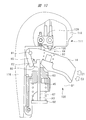
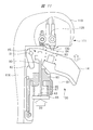
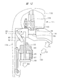
- FIGS. 6, 7 and 8 are the same as those of the driving machine 10 shown in FIGS. 1, 2, 3, 4, and 5.
- the protrusion 80 and the arm 82 may not be provided.
- FIG. 9 shows the second embodiment of the driving machine.
- the driving machine 100 includes a housing 111, an electric motor 112, a striking portion 113, an injection portion 114, and a power supply 115.
- the housing 111 includes a cylinder case 116, a motor case 117, a handle 118, a head cover 119, and a mounting portion 120.
- the cylinder case 116 has a tubular shape, and the motor case 117 is connected to the cylinder case 116.
- the handle 118 is provided so as to project from the cylinder case 116.
- the mounting portion 120 connects the handle 118 and the motor case 117.
- the power supply 115 is a battery that can be attached to and detached from the mounting portion 120.
- the power supply 115 includes a storage case and a battery cell housed in the storage case.
- Battery cells include lithium ion batteries, nickel metal hydride batteries, lithium ion polymer batteries and nickel cadmium batteries.
- a battery cell is a secondary battery capable of repeating charging and discharging.
- the cylinder 121 is fixedly provided in the cylinder case 116.
- the striking portion 113 can operate in the first direction D1 and the second direction D2 along the center line A5 of the cylinder 121.
- the striking portion 113 has a piston 122 and a driver blade 123.
- the piston 122 is housed in the cylinder 121.
- the driver blade 123 has a shaft shape, and the driver blade 123 has a rack along the center line A5. ..
- the accumulator container 124 is provided in the head cover 119, and the accumulator container 124 is fixed to the cylinder 121.
- the pressure chamber 125 is formed from the inside of the accumulator container 124 to the inside of the cylinder 121.
- the pressure chamber 125 is filled with gas.
- the gas may be a compressible gas, and the gas may be an inert gas such as nitrogen gas or a rare gas in addition to air. In the present disclosure, an example in which the pressure chamber 125 is filled with air will be described.
- the bumper 126 is provided in the cylinder case 116. A part of the bumper 126 is arranged in the cylinder 121.
- the bumper 126 is made of rubber or urethane.
- the bumper 126 is annular.
- the injection portion 114 is fixed to the cylinder case 116.
- the injection section 114 has an injection path 127.
- the magazine 135 is attached to the injection section 114.
- the magazine 135 accommodates the nail 131.
- a feeder 132 is provided in the magazine 135, which feeds the nail 131 to the ejection path 127.
- the push lever 128 is attached to the injection portion 114, and the push lever 128 can move in the center line A5 direction with respect to the injection portion 114.
- the trigger 14 and the guide member 63 are provided in the cylinder case 116. Further, the guide member 63 operably supports the transmission member 67 along the center line A3.
- the center line A3 is parallel to the center line A5.
- the spring 45 urges the transmission member 67 in a direction away from the handle 118.
- the transmission member 67 has a protrusion 80.
- the transmission member 67 has a plate 68, and the operating force of the push lever 128 is transmitted to the plate 68.
- the trigger 14 is arranged between the guide member 63 and the handle 118 in the direction along the center line A3.
- the trigger 14 has an arm 82 and a boss portion 83.
- a spring 84 is provided between the handle 118 and the boss portion 83.
- the spring 84 is made of metal, and the spring 84 urges the trigger 14 toward the guide member 63.
- a trigger switch 129 is provided on the handle 118.
- the trigger switch 129 has a contact 130, which is exposed to the outer B1 of the housing 111.
- the contact 130 is arranged in the operating region of the boss portion 83.
- the control unit 136 is provided in the mounting unit 120, and the signal of the trigger switch 129 is input to the control unit 136.
- the control unit 136 is composed of a microcomputer having an input port, an output port, an arithmetic processing unit, a storage unit, and the like.
- a push switch for detecting whether the push lever 128 is pressed against or separated from the mating material W1 is provided in the injection unit 114, and the signal of the push switch is input to the control unit 136.
- the control unit 136 controls the supply and stop of electric power from the power supply 115 to the electric motor 112.
- the electric motor 112 is arranged in the motor case 117.
- a speed reducer 133 and a wheel 134 are provided.
- the speed reducer 133 is a mechanism for transmitting the rotational force of the electric motor 112 to the wheel 134.
- the speed reducer 133 has a plurality of planetary gear mechanisms, and the speed reducer 133 reduces the rotation speed of the wheel 134 with respect to the rotation speed of the electric motor 112.
- a pinion is provided on the outer peripheral surface of the wheel 134. The pinion can engage and disengage the rack of driver blades 123.
- the transmission member 67 stops at the initial position and the trigger 14 is initially set, as shown in FIG. It is stopped at the position.
- the boss portion 83 is separated from the contact 130 and the trigger switch 129 is turned off.
- the control unit 136 stops the supply of electric power from the power supply 115 to the electric motor 112.
- the striking portion 113 is stopped at the standby position.
- the standby position of the striking portion 113 is a position in the direction along the center line A5.
- the operating force of the push lever 128 is transmitted to the transmission member 67.
- the transmission member 67 operates from the initial position in FIG. 10 in the third direction D3 as shown in FIG. 11 and stops at the operating position.
- the trigger switch 129 is off, and the control unit 136 stops supplying electric power from the power supply 115 to the electric motor 112.
- the control unit 136 detects that the push switch is turned on and the trigger switch 129 is turned on, the power supply 115 supplies electric power to the electric motor 112.
- the rotational force of the electric motor 112 is transmitted to the wheel 134 via the speed reducer 133.
- the rotational force of the wheel 134 causes the striking portion 113 to operate in the second direction D2 from the standby position toward the top dead center, that is, to rise.
- the pressure in the pressure chamber 125 rises.
- the striking portion 113 When the pinion of the wheel and the rack of the driver blade 123 are released, the striking portion 113 operates in the first direction D1 under the pressure of the pressure chamber 125, that is, descends, and the driver blade 123 strikes the nail 131.
- the piston 122 collides with the bumper 126.
- the position of the striking portion 113 in the state where the piston 122 collides with the bumper 126 is the bottom dead center.
- the control unit 136 stops the supply of electric power to the electric motor 112. Therefore, the striking portion 113 stops at the standby position.
- the transmission member 67 When the push lever 128 separates from the mating material W1 due to the reaction of the striking portion 113 driving the nail 131 into the mating material W1, the transmission member 67 operates in the fourth direction D4 from the operating position of FIG. 12 by the urging force of the spring 45. Then, it stops at the initial position shown in FIG. While the transmission member 67 is operating from the operating position to the initial position, the protrusion 80 is pressed against the arm 82. A part of the operating force of the transmission member 67 is converted into a force for operating the trigger 14 in the release direction E2 in FIG. 12, and the trigger 14 returns to the initial position shown in FIG. 10 and stops.
- the spring 45 serves as a return mechanism for operating the trigger 14 from the operating position to the initial position. Further, the urging force of the spring 45 is not transmitted in the direction in which the trigger 14 is operated clockwise in FIG. Therefore, it is possible to suppress an increase in the operating force required to operate the trigger 14 from the initial position to the operating position.
- the driving machines 10 and 100 are examples of driving machines. Housings 11 and 111 are examples of housings.
- the addition direction E1 is an example of the addition direction.
- the release direction E2 is an example of the release direction.
- the addition direction E1 and the release direction E2 are opposite to each other.
- the addition direction can be defined as the going direction.
- the release direction can be defined as the return direction.
- the trigger 14 is an example of an operating member.
- the striking portions 13 and 113 are examples of striking portions.
- the first direction D1 is an example of the first direction.
- the first direction can be defined as the striking direction.
- the second direction D2 is an example of the second direction.
- the second direction can be defined as the return direction.
- the piston upper chamber 36, the pressure chamber 125, the speed reducer 133, and the electric motor 112 are examples of the drive unit.
- the push levers 16 and 128 are examples of contact members.
- the auxiliary mechanism 85 and the valve 90 are examples of the auxiliary mechanism, respectively.
- the state in which the protrusion 80 is separated from the arm 82 is an example of the first state of the auxiliary mechanism.
- the state in which the protrusion 80 contacts the arm 82 and the urging force of the spring 45 can be applied to the trigger 14 as the urging force in the release direction E2 is the state of the auxiliary mechanism.
- the state in which the valve 90 closes the support hole 91 is an example of the first state of the auxiliary mechanism.
- the state in which the valve 90 opens the support hole 91 is an example of the second state of the auxiliary mechanism.
- the piston upper chamber 36 is an example of a pressure chamber.
- the trigger valve 51 is an example of a switching mechanism.
- the operating state of the trigger valve 51 is an example of a striking state.
- the initial state of the trigger valve 51 is an example of a non-striking state.
- the pressure chamber 125 is an example of a gas spring.
- the pressure of the compressed gas in the pressure chamber 125 is an example of elastic energy.
- the electric motor 112 is an example of an electric motor.
- the nails 73 and 131 are examples of fasteners.
- the fastener may be in the shape of a rod or an arch.
- the driving machine is not limited to the disclosed embodiment, and various modifications can be made without departing from the spirit of the invention.
- the operating member and the contact member include levers, buttons, arms, and the like, respectively.
- the operation of the operating member may be either a rotational operation within a predetermined angle range or a linear reciprocating operation.
- the "driving unit that operates the striking unit in the first direction" may be either the first driving unit or the second driving unit.
- the first drive unit operates the striking unit in the first direction and does not operate the striking unit in the second direction.
- the second drive unit operates the striking unit in the second direction and then operates the striking unit in the first direction.
- the element that applies the operating force in the fourth direction D4 to the transmission member 67 that is, the return mechanism that applies the operating force in the release direction to the trigger 14, is a gas spring or synthetic rubber instead of the metal spring 45. It is also possible to use a permanent magnet. For example, it is possible to attach permanent magnets of opposite polarity to the plate 68 and the guide member 63, respectively, and apply the operating force of the fourth direction D4 to the transmission member 67 by the repulsive force between the permanent magnets.
- the housing is an element that constitutes a part of the main body of the driving machine, and the housing includes a casing, a shell, and the like.
- a metal spring may be used as the spring for operating the striking portion 113 in the first direction D1 instead of the pressure chamber 125 constituting the gas spring.
- the metal spring elastically deforms and stores elastic energy.
- the striking portion can be operated in the first direction by the elastic energy of the metal spring.
Landscapes
- Engineering & Computer Science (AREA)
- Mechanical Engineering (AREA)
- Portable Nailing Machines And Staplers (AREA)
Abstract
操作部材の操作性を向上可能な打込機を提供する。ハウジング(11)に設けられて付加方向(E1)及び解除方向(E2)に作動するトリガ(14)と、ハウジング(11)により支持され、かつ、留具を打ち込む第1方向に作動可能な打撃部と、トリガ(14)が付加方向(E1)に作動すると、打撃部を第1方向に作動させる駆動部と、ハウジング(11)に対して作動可能に設けられ、かつ、留具を打ち込む相手材に接触または離間可能な接触部材と、を備えた打込機(10)であって、トリガ(14)に対する解除方向(E2)の付勢力の付加及び非付加が可能な補助機構(85)が設けられ、補助機構(85)は、トリガ(14)が付加方向(E1)に作動する場合に、トリガ(14)に対する解除方向(E2)の付勢力を非付加とする第1状態と、トリガ(14)が解除方向(E2)に作動する場合に、解除方向(E2)の付勢力を付加する第2状態と、を有する。
Description
本発明は、留具を打撃する打撃部と、打撃部を作動させる駆動部と、を有する打込機に関する。
留具を打撃する打撃部と、打撃部を作動させる駆動部と、を有する打込機の一例が、特許文献1に記載されている。特許文献1に記載された打込機は、ハウジング、シリンダ、バルブ、駆動部としての圧力室、エキゾーストバルブ室、補助圧力室、蓄圧室、打撃部、エキゾーストバルブ、操作部材としてのトリガ、プッシュレバ、戻り空気室、射出部、マガジンを有する。また、トリガ及びプッシュレバの作動をバルブに伝達する機構が設けられている。マガジンは留具を収容し、留具は射出部に供給される。
使用者がトリガ及びプッシュレバに対する操作力を解除すると、バルブは初期状態を保持する。初期状態にあるバルブは、蓄圧室と補助圧力室と接続し、かつ、蓄圧室とエキゾーストバルブ室を接続する。このため、シリンダは、バルブシートに押し付けられて停止し、シリンダは、蓄圧室と圧力室とを遮断する。また、エキゾーストバルブは、ハウジングの外部と圧力室とを接続する。したがって、打撃部はバルブシートに接触した上死点で停止する。
使用者がトリガに操作力を付加し、かつ、プッシュレバを相手材に押し付けると、バルブは初期状態から作動状態に切り替わる。作動状態のバルブは、蓄圧室と補助圧力室と遮断し、かつ、蓄圧室とエキゾーストバルブ室とを遮断する。このため、シリンダは、バルブシートに押し付けられて停止し、シリンダは、蓄圧室と圧力室とを接続する。また、エキゾーストバルブは、ハウジングの外部と圧力室とを遮断する。すると、蓄圧室の圧縮空気が圧力室に供給され、打撃部は上死点から下死点に向けて作動し、打撃部は留具を打撃し、かつ、下死点に到達する。打撃部が上死点から下死点に向けて作動中、ピストン下室の空気圧が上昇する。
使用者がプッシュレバを相手材から離間させ、かつ、トリガに対する操作力を解除すると、バルブが作動状態から初期状態に戻る。打撃部はピストン下室の圧力で作動し、かつ、打撃部は上死点で停止する。
本願発明者は、バルブを作動状態から初期状態に切り替えるにあたり、操作部材に付加した操作力を解除する操作が必要であり操作性が低下する、ということを認識した。
本発明の目的は、操作部材の操作性を向上可能な打込機を提供することである。
一実施形態の打込機は、ハウジングに設けられ、使用者が操作力を付加すると付加方向に作動し、かつ、使用者が操作力を解除すると前記付加方向とは逆の解除方向に作動する操作部材と、前記ハウジングにより支持され、かつ、留具を打ち込む第1方向、及び前記第1方向とは逆の第2方向に作動できる打撃部と、前記操作部材が前記付加方向に作動すると、前記打撃部を前記第1方向に作動させる駆動部と、前記ハウジングに対して作動可能に設けられ、かつ、前記留具を打ち込む相手材に接触または離間ができる接触部材と、を備えた打込機であって、前記操作部材に対する前記解除方向の付勢力の付加と非付加とを切り替え可能な補助機構が設けられ、前記補助機構は、前記操作部材が前記付加方向に作動する場合に、前記操作部材に対する前記解除方向の付勢力を非付加とする第1状態と、前記操作部材が前記解除方向に作動する場合に、前記解除方向の付勢力を付加する第2状態と、を有する。
一実施形態の打込機は、操作部材の操作性を向上可能である。
次に、本発明の打込機に含まれるいくつかの実施形態のうち、代表的な打込機を、図面を参照して説明する。
(実施形態1) 打込機の実施形態1を、図1を参照して説明する。打込機10は、ハウジング11、シリンダ12、打撃部13、射出部15、トリガバルブ51、トリガ14及びプッシュレバ16を有する。また、マガジン17が打込機10に取り付けられている。ハウジング11は、筒形状の胴部18と、胴部18に固定したヘッドカバー21と、胴部18に接続されたハンドル19と、を有する。ハンドル19は、胴部18の外面から突出している。
図1及び図2のように、蓄圧室20が、ハンドル19の内部、胴部18の内部、ヘッドカバー21の内部に亘って形成されている。エアホースがハンドル19に接続される。圧縮気体としての圧縮空気は、エアホースを介して蓄圧室20内に供給される。シリンダ12は胴部18内に設けられている。
ヘッドバルブ31がヘッドカバー21内に設けられている。ヘッドバルブ31は、シリンダ12の中心線A1方向に移動可能である。制御室27が、ヘッドカバー21とヘッドバルブ31との間に形成されている。付勢部材28が、制御室27に設けられている。付勢部材28は、一例として、金属製の圧縮コイルスプリングである。付勢部材28は、ヘッドバルブ31を中心線A1方向でシリンダ12に近付ける向きで付勢する。ヘッドバルブ31は、蓄圧室20の圧力で、常時、シリンダ12から離間する方向に付勢されている。
ストッパ29がヘッドカバー21内に設けられている。ストッパ29は一例として合成ゴム製である。ヘッドカバー21は、排気通路24を有する。排気通路24は、ハウジング11の外部B1につながっている。
シリンダ12は、胴部18に対して中心線A1に沿った方向に位置決め固定されている。シリンダ12において、中心線A1に沿った方向でヘッドバルブ31に最も近い箇所の端部に、バルブシート32が取り付けられている。バルブシート32は環状であり、かつ、合成ゴム製である。
打撃部13は、ピストン34と、ピストン34に固定されたドライバブレード35と、を有する。ピストン34は、シリンダ12内に配置され、打撃部13は、中心線A1に沿って直動できる。つまり、打撃部13は、第1方向D1及び第2方向D2に沿って往復作動できる。第1方向D1は、図1及び図2において下降と定義可能であり、第2方向D2は、上昇と定義可能である。第1方向D1と第2方向D2とは、逆向きである。ピストン34の外周面にシール部材99が取り付けられている。ピストン上室36が、ストッパ29とピストン34との間に形成される。
射出部15は、胴部18に対して、中心線A1に沿った方向でヘッドカバー21が設けられている個所とは反対の端部に固定されている。バンパ37が、シリンダ12内に設けられている。バンパ37は、シリンダ12内において、中心線A1方向で射出部15に最も近い位置に配置されている。バンパ37は、合成ゴム製、または、シリコンゴム製である。バンパ37は軸孔38を有し、ドライバブレード35は軸孔38内で中心線A1方向に移動可能である。シリンダ12内において、ピストン34とバンパ37との間にピストン下室39が形成されている。ピストン下室は、軸孔につながっている。シール部材99は、ピストン下室39とピストン上室36とを気密に遮断する。
環状の隔壁40が胴部18内に設けられている。隔壁40はシリンダ12の外周を囲むように配置されている、シリンダ12を中心線A1と交差する方向にハウジングに対して位置決めする。戻り空気室43が、シリンダ12の外面と胴部18との間に形成されている。隔壁40は、蓄圧室20と戻り空気室43とを隔てている。
シリンダ12を径方向に貫通する通路41,42が設けられている。通路42は、中心線A1方向で通路41と射出部15との間に配置されている。通路41は、ピストン下室39と戻り空気室43とをつなぐ。図3に示す逆止弁44が、シリンダ12の外面に取り付けられている。逆止弁44は、シリンダ12内の空気圧で通路41を開く。逆止弁44は、戻り空気室43の空気圧で通路41を閉じる。通路42は、戻り空気室43とピストン下室39とを、常に接続している。ピストン下室39及び戻り空気室43内に亘って空気が存在している。
図1のように、トリガバルブ51が、胴部18とハンドル19との接続箇所に設けられている。トリガバルブ51は、図3、図4及び図5のように、プランジャ52、ボディ53、弁体55及びスプリング69を有する。ボディ53及び弁体55は共に筒形状であり、ボディ53及び弁体55は、共に中心線A2を中心として同心状に配置されている。図1は、中心線A1と中心線A2とが平行である例を示す。ボディ53はハウジング11に固定されている。弁体55は、ボディ53内で中心線A2に沿った方向に作動可能である。ボディ53は通路56、排気通路61及び軸孔62を有する。通路56は、通路57を介して制御室27に接続されている。通路57はハウジング11に設けられている。
また、ハンドル19は通路58を有し、通路58は、蓄圧室20とボディ53の内部とを接続している。排気通路61はハウジング11の外部B1につながっている。プランジャ52は、軸孔62及び弁体55内に亘って配置されている。プランジャ52は中心線A2に沿った方向に移動可能である。プランジャ52において、中心線A2に沿った方向における端部が、ハウジング11の外部B1に配置されている。スプリング69は、一例として金属製である。スプリング69は、プランジャ52を中心線A2に沿った方向でトリガ14に近付ける向きで付勢している。スプリング69は、弁体55を中心線A2に沿った方向で通路58に近づける向きで付勢している。
図1に示す射出部15は、一例として、金属製または非鉄金属製である。射出部15は、筒部70と、筒部70の外周面に接続されたフランジ71と、を有する。フランジ71は、胴部18に固定されている。筒部70は、フランジ71から中心線A1に沿った方向に突出しており、筒部70は射出路72を有する。射出路72は孔または空間であり、中心線A1が射出路72に位置する。ドライバブレード35は射出路72内で中心線A1に沿った方向に作動可能である。マガジン17は、射出部15に取り付けられている。マガジン17は釘73を収容する。マガジン17は、フィーダ74を有し、フィーダ74はマガジン17内の釘73を射出路72に送る。
プッシュレバ16は、射出部15に取り付けられている。プッシュレバ16は、射出部15に対して中心線A1に沿った方向に作動できる。ガイド部材63及びホルダ64が、ハウジング11、一例として胴部18の外面に取り付けられている。ガイド部材63及びホルダ64は、中心線A2に沿った方向で、トリガバルブ51と射出部15との間に配置されている。ホルダ64は筒形状であり、ホルダ64は伝達部材65を移動可能に支持している。伝達部材65はプッシュレバ16と共に中心線A3に沿った方向に移動可能である。中心線A3は、中心線A2と平行である。
ガイド部材63は、伝達部材67を移動可能に支持している。伝達部材67及び伝達部材65の移動方向は、中心線A3に沿った方向である。伝達部材67は軸形状であり、伝達部材67の端部にプレート68が設けられている。スプリング45が、ガイド部材63とプレート68との間に配置されている。スプリング45は、伝達部材67をトリガバルブ51から離間させる向きで付勢する。伝達部材67は、プレート68がホルダ64に押し付けられて初期位置で停止する。スプリング45は、一例として金属製である。ガイド部材63は、伝達部材67を中心線A3に沿った方向に移動させる。伝達部材67は突起部80を有する。突起部80は、伝達部材67における中心線A3に沿った方向で、ガイド部材63とトリガバルブ51との間に位置する箇所に設けられている。突起部80は、伝達部材67から中心線A3に交差する向きで突出している。
図3、図4及び図5のように、トリガ14は、ハウジング11の外部B1に配置されている。トリガ14は、中心線A2に沿った方向でトリガバルブ51とガイド部材63との間に配置されている。トリガ14は、支持軸81を介して胴部18に取り付けられている。トリガ14は、支持軸81を中心として回転可能である。
図3でトリガ14が反時計回りに作動する方向は、付加方向E1と定義可能である。図3でトリガ14が時計回りに作動する方向は、解除方向E2と定義可能である。付加方向E1は、トリガ14がトリガバルブ51に近づく方向である。解除方向E2は、トリガ14がトリガバルブ51から離間する方向である。付加方向E1と解除方向E2とは、逆向きである。トリガ14が、ボディ53またはガイド部材63に接触することで、トリガ14の作動範囲が制限される。
トリガ14は、アーム82及びボス部83を有する。突起部80、アーム82、スプリング45は、補助機構85を構成している。ボス部83とボディ53との間にスプリング84が設けられている。トリガ14は、スプリング84によって支持軸81を中心として、図3の時計回りに付勢される。スプリング84は、一例として金属製のスプリングである。伝達部材67の突起部80は、中心線A3に対して交差する方向で、アーム82とボス部83との間に位置する。
次に、打込機10を用いて、釘73を相手材W1に打ち込む例を説明する。相手材W1は、木材、石膏ボード、コンクリート等を含む。先ず、使用者が図1に示すプッシュレバ16を相手材W1から離間させていると、プレート68がホルダ64に押し付けられて伝達部材67が初期位置で停止している。また、使用者がトリガ14に対する操作力を解除していると、トリガ14は、図3のようにガイド部材63に接触した初期位置で停止している。中心線A3に沿った方向における突起部80の位置は、アーム82の先端と同じ位置である。
トリガ14が初期位置で停止していると、トリガバルブ51は、図3に示す初期状態を保持している。トリガバルブ51が初期状態であると、プランジャ52は、スプリング69の付勢力でボディ53に押し付けられた初期位置で停止している。弁体55は、スプリング69によりボディ53に押し付けられた初期位置で停止している。弁体55は、蓄圧室20と通路56とを接続し、かつ、通路56と排気通路61とを遮断している。
蓄圧室20の圧縮空気が制御室27に供給され、ヘッドバルブ31は、図2のようにバルブシート32に押し付けられて停止している。ヘッドバルブ31は、蓄圧室20とピストン上室36とを遮断し、ピストン上室36と排気通路24とをつないでいる。ピストン上室36の圧力は、大気圧と同じである。打撃部13は、ピストン34がストッパ29に最も接近した位置、つまり、上死点で停止している。打撃部13は、シール部材99とシリンダ12との摩擦力、または、シール部材99とシリンダ12との係合力により、上死点で停止している。
次に、使用者がプッシュレバ16を相手材W1に押し付けると、プッシュレバ16の作動力は、伝達部材65を介して伝達部材67に伝達される。伝達部材67は、スプリング45の力に抗してトリガバルブ51に接近する第3方向D3で作動し、伝達部材67は、図4に示す作動位置で停止する。第3方向D3は、中心線A3に沿った方向である。伝達部材67が作動位置で停止すると、突起部80は、中心線A3に沿った方向で、アーム82の先端と、ボディ53との間に位置する。
使用者がトリガ14に指を押し付けて操作力を付加し、かつ、トリガ14をスプリング84の力に抗して反時計回りに回転させると、図5のように、トリガ14がボディ53またはハンドル19に接触した作動位置で停止する。トリガ14の作動力は、ボス部83を介してプランジャ52に伝達される。このため、プランジャ52はスプリング69の力に抗して初期位置から通路58に向けて作動し、プランジャ52が作動位置で停止する。また、トリガ14が初期位置から付加方向E1で作動する過程で、突起部80はアーム82から離間している。このため、突起部80は、トリガ14が付加方向E1に作動することを妨げない。
プランジャ52が初期位置から作動位置へ移動すると、トリガバルブ51は初期状態から作動状態に切り替わる。トリガバルブ51が、図5に示す作動状態になると、弁体55が蓄圧室20の圧力で通路58から離間する向きで作動し、かつ、弁体55はボディ53に押し付けられた作動位置で停止する。作動位置で停止した弁体55は、蓄圧室20と通路56とを遮断し、かつ、通路56を排気通路61とを接続する。このため、制御室27の圧縮空気は、通路57、通路56及び排気通路60を介して外部B1に排出され、制御室27の圧力が大気圧と同じになる。
制御室27の圧力が大気圧と同じになると、ヘッドバルブ31は、蓄圧室20の圧力で付勢部材28の付勢力に抗して作動し、かつ、ストッパ29に接触して作動位置で停止する。作動位置で停止したヘッドバルブ31は、蓄圧室20とピストン上室36とを接続し、かつ、ピストン上室36と排気通路24とを遮断する。ピストン上室36の圧力が上昇し、打撃部13は上死点から下死点に向けて作動し、ドライバブレード35が射出路72内の釘73を打撃する。打撃された釘73は、相手材W1に打ち込まれる。打撃部13が上死点から下死点に向けて作動中、ピストン下室39及び戻り空気室43の圧力が上昇する。また、逆止弁44が開き、ピストン上室36の空気が通路41を通って戻り空気室43へ流れ込む。
打撃部13が釘73を相手材W1に打ち込んだ後、ピストン34がバンパ37に衝突し、バンパ37は打撃部13の運動エネルギの一部を吸収する。ピストン34がバンパ37に衝突した時点における打撃部13の位置は、下死点である。打撃部13が下死点に到達すると、逆止弁44は通路41を閉じる。ピストン34がバンパに押し付けられていると、ピストン34はピストン下室39と軸孔38とを遮断する。
プッシュレバ16は、打撃部13が釘73を相手材W1に打ち込まれた反動で相手材W1から離間する。すると、伝達部材67は、スプリング45の力により、図5において第4方向D4に作動する。第4方向D4は、中心線A3に沿った方向である。そして、プレート68が図3のようにホルダ64に押し付けられると、伝達部材67及びプッシュレバ16が初期位置で停止する。伝達部材67が中心線A3に沿ってトリガバルブ51から離間する向きで作動中、突起部80がアーム82に押し付けられる。伝達部材67の作動力の一部は、図5でトリガ14を時計回りに作動させる力に変換され、トリガ14は、図3に示す初期位置に戻って停止する。
つまり、伝達部材67及びプッシュレバ16を作動位置から初期位置に戻す動力源であるスプリング45の力を利用して、トリガ14を図5の作動位置から図3の初期位置へ戻すことができる。このため、使用者はトリガ14に付加した操作力を解除する、または、指をトリガ14から離間させるという操作を、意図して行わずに済む。したがって、トリガ14に対する操作性が向上する。
このように、スプリング45は、トリガ14を作動位置から初期位置へ作動させる戻し機構の役割りを有する。トリガ14を初期位置から作動位置へ作動させる場合、スプリング45の付勢力は、図3でトリガ14を時計回りに作動させる向きに伝達されない。このため、トリガ14を初期位置から作動位置へ作動させるために必要な操作力が増加することを抑制できる。トリガ14を初期位置から作動位置へ作動させるために必要な操作力は、スプリング45,84の付勢力に応じて定まる。
さらに、トリガ14が作動位置へ付加方向E1に作動する行程において、突起部80はアーム82から離間している。このため、トリガ14が初期位置から作動位置へ付加方向E1に作動する行程において、スプリング45の付勢力は、トリガ14の解除方向E2には非付加である。
なお、プッシュレバ16が相手材W1から離間している状態で、使用者が図3に示すトリガ14に操作力を付加すると、アーム82が突起部80に接触する。このため、トリガ14は、反時計回りに回転することが阻止され、トリガバルブ51は初期状態を保持する。
さらに、打撃部13が下死点に到達した後、プッシュレバ16が相手材W1から離間するか、または、トリガ14に対する操作力が解除されると、トリガバルブ51は作動状態から初期状態に切り替わる。このため、打撃部13は、ピストン下室39の圧力で第1方向D1に作動し、打撃部13は上死点で停止する。さらに、ピストン34がバンパ37から離間すると、ピストン下室39の空気が軸孔38から外部B1へ排出される。打撃部13が上死点に到達した後、ピストン下室39及び戻り空気室43の圧力は、大気圧と略同じになる。
図6、図7及び図8は、戻し機構の他の具体例を示す断面図である。バルブ90が、ハウジング11、一例としてハンドル19に設けられている。ハンドル19が胴部18から突出する方向、つまり、中心線A2に対して交差する方向で、トリガバルブ51は、バルブ90と胴部18との間に位置する。バルブ90は、支持孔91、プランジャ92及び付勢部材93を有する。
支持孔91は、蓄圧室20と外部B1とをつなぐ。プランジャ92は、支持孔91に配置され、プランジャ92は、ハンドル19に対して中心線A4に沿った方向に移動可能である。中心線A4は、中心線A2と平行である。環状のシール部材94がプランジャ92の外周面に取り付けられている。
プランジャ92の長さ方向の一部は外部B1に配置され、プランジャ92のう外部B1に配置されている箇所にプレート95が設けられている。付勢部材93は、一例として金属製のスプリングであり、付勢部材93は、プランジャ92をトリガ14に向けて付勢している。トリガ14は接触部96を有する。ボス部83は、トリガ14の長さ方向で、接触部96と支持軸81との間に位置する。プレート95は、接触部96の作動領域に配置されている。
トリガ14が、図6のように初期位置で停止していると、接触部96はプレート95から離間している。シール部材94が支持孔91の内面に押し付けられた状態で、プランジャ92が初期位置で停止している。シール部材94は、蓄圧室20と外部B1とを気密に遮断している。プッシュレバ16が相手材W1に押し付けられると、伝達部材67が初期位置から図7のように作動位置に移動して停止する。接触部96は、プレート95から離間している。
使用者がプッシュレバ16を相手材W1に押し付けた状態で、トリガ14に操作力を付加して、トリガ14を図7で示す、付加方向E1で作動させると、接触部96がプレート95に押し付けられる。プランジャ92が付勢部材93の力に抗して蓄圧室20に近づく向きで作動する。トリガ14が、図8のように作動位置で停止すると、プランジャ92は作動位置で停止する。プランジャ92が作動位置で停止すると、シール部材94が支持孔91の内面から離間し、支持孔91は、蓄圧室20と外部B1とをつなぐ。蓄圧室20の圧縮空気は、支持孔91を通ってトリガ14に吹き付けられる。使用者がトリガ14に対する操作力を解除する際に、支持孔91からトリガ14に吹き付けられる圧縮空気の運動エネルギにより、トリガ14が解除方向E2で付勢される。したがって、トリガ14を作動位置から初期位置に戻す場合の操作性が向上する。
さらに、トリガ14に付加した操作力を解除すると、プランジャ92は付勢部材93の付勢力で作動し、シール部材94が支持孔91の内面に押し付けられ、かつ、プランジャ92が初期位置で停止する。つまり、バルブ90は初期状態に戻る。
このように、バルブ90が、トリガ14を作動位置から初期位置へ作動させる戻し機構の役割りを果たす。トリガ14を初期位置から作動位置へ作動させる途中において、バルブ90は支持孔91を閉じており、蓄圧室20の圧縮空気は、支持孔91から外部B1に排気されない。つまり、図7でトリガ14を時計回りに作動させる向きの力は生じない。このため、トリガ14を初期位置から作動位置へ作動させるために必要な操作力が増加することを抑制できる。
トリガ14が付加方向E1に作動する過程で、接触部96がプレート95から離間していると、蓄圧室20の圧縮空気が、支持孔91から外部B1へ排出されることはない。つまり、トリガ14が付加方向E1に作動する過程で、圧縮空気の運動エネルギは、トリガ14の解除方向E2には非付加である。
また、図6、図7及び図8に示す打込機10の他の構造及び機能は、図1、図2、図3、図4及び図5に示す打込機10と同じである。なお、図6、図7及び図8において、突起部80及びアーム82は、設けられていなくてもよい。
(実施形態2) 図9は打込機の実施形態2を示す。打込機100は、ハウジング111、電動モータ112、打撃部113、射出部114及び電源115を有する。ハウジング111は、シリンダケース116、モータケース117、ハンドル118、ヘッドカバー119及び装着部120を有する。シリンダケース116は筒形状であり、モータケース117はシリンダケース116に接続されている。ハンドル118は、シリンダケース116から突出して設けられている。装着部120は、ハンドル118とモータケース117とを接続している。
電源115は、装着部120に取り付け及び取り外しが可能なバッテリである。電源115は、収容ケースと、収容ケース内に収容した電池セルと、有する。電池セルは、リチウムイオン電池、ニッケル水素電池、リチウムイオンポリマー電池及びニッケルカドミウム電池を含む。電池セルは、充電と放電とを繰り返すことの可能な二次電池である。
シリンダ121がシリンダケース116内に固定して設けられている。打撃部113は、シリンダ121の中心線A5に沿って第1方向D1及び第2方向D2で作動可能である。打撃部113は、ピストン122及びドライバブレード123を有する。ピストン122がシリンダ121内に収容されている。ドライバブレード123は軸形状であり、ドライバブレード123は、中心線A5に沿ったラックを有する。。
蓄圧容器124がヘッドカバー119内に設けられ、蓄圧容器124はシリンダ121に固定されている。圧力室125が、蓄圧容器124内からシリンダ121内に亘って形成されている。気体が圧力室125に充填されている。気体は圧縮性の気体であればよく、気体は、空気の他、不活性ガス、例えば、窒素ガス、希ガスを用いることができる。本開示では、圧力室125に空気が充填されている例を説明する。
バンパ126がシリンダケース116内に設けられている。バンパ126の一部は、シリンダ121内に配置されている。バンパ126は、ゴム製またはウレタン製である。バンパ126は環状である。射出部114は、シリンダケース116に固定されている。射出部114は、射出路127を有する。マガジン135が射出部114に取り付けられている。マガジン135は釘131を収容する。フィーダ132がマガジン135に設けられ、フィーダ132は釘131を射出路127に送る。
プッシュレバ128が射出部114に取り付けられ、プッシュレバ128は射出部114に対して中心線A5方向に移動できる。トリガ14及びガイド部材63は、シリンダケース116に設けられている。また、ガイド部材63は、伝達部材67を中心線A3に沿って作動可能に支持している。中心線A3は、中心線A5と平行である。スプリング45が伝達部材67をハンドル118から離間する向きに付勢している。伝達部材67は、突起部80を有する。
伝達部材67はプレート68を有し、プッシュレバ128の作動力は、プレート68に伝達される。トリガ14は、中心線A3に沿った方向で、ガイド部材63とハンドル118との間に配置されている。トリガ14は、アーム82及びボス部83を有する。スプリング84が、ハンドル118とボス部83との間に設けられている。スプリング84は金属製であり、スプリング84は、トリガ14をガイド部材63に向けて付勢する。
トリガスイッチ129がハンドル118に設けられている。トリガスイッチ129は、接触子130を有し、接触子130は、ハウジング111の外部B1に露出している。トリガ14が支持軸81を中心として作動するにあたり、接触子130は、ボス部83の作動領域に配置されている。
制御部136が装着部120内に設けられ、トリガスイッチ129の信号が制御部136に入力される。制御部136は、入力ポート、出力ポート、演算処理部及び記憶部等を有するマイクロコンピュータによって構成されている。プッシュレバ128が相手材W1に押し付けられているか離間しているかを検出するプッシュスイッチが、射出部114に設けられ、プッシュスイッチの信号は、制御部136に入力される。制御部136は、電源115から電動モータ112に対する電力の供給及び停止を制御する。
電動モータ112は、モータケース117内に配置されている。減速機133及びホイール134が設けられている。減速機133は、電動モータ112の回転力をホイール134に伝達する機構である。減速機133は、複数の遊星歯車機構を有し、減速機133は、電動モータ112の回転速度に対してホイール134の回転速度を減速する。ホイール134の外周面にピニオンが設けられている。ピニオンは、ドライバブレード123のラックに係合及び解放が可能である。
次に、打込機100の使用例を説明する。使用者がプッシュレバ128を相手材W1から離間させ、かつ、トリガ14に対する操作力を解除していると、図10のように、伝達部材67は初期位置で停止し、かつ、トリガ14は初期位置で停止している。トリガ14が初期位置で停止していると、ボス部83は接触子130から離間し、トリガスイッチ129はオフする。制御部136は、トリガスイッチ129がオフされ、かつ、プッシュスイッチがオフしていると、電源115から電動モータ112に対する電力の供給を停止する。打撃部113は待機位置で停止している。打撃部113の待機位置は、中心線A5に沿った方向の位置である。
使用者がトリガ14に対する操作力を解除した状態で、プッシュレバ128を相手材W1に押し付けると、プッシュレバ128の作動力が伝達部材67に伝達される。伝達部材67は、図10の初期位置から図11のように第3方向D3で作動し、かつ、作動位置で停止する。トリガスイッチ129はオフであり、制御部136は、電源115から電動モータ112に対する電力の供給を停止している。
使用者がプッシュレバ128を相手材W1に押し付けた状態で、トリガ14に操作力を付加してトリガ14を図11で示す付加方向E1で作動させる。すると、図12のように、トリガ14がハンドル118に接触した作動位置で停止する。トリガ14が作動位置にあると、ボス部83が接触子130を押し、トリガスイッチ129がオンする。
制御部136は、プッシュスイッチがオンし、かつ、トリガスイッチ129がオンしていることを検出すると、電源115から電動モータ112に電力を供給する。電動モータ112の回転力は、減速機133を経由してホイール134に伝達される。ホイールのピニオンと、ドライバブレード123のラックとが係合していると、ホイール134の回転力で打撃部113が待機位置から上死点に向けて第2方向D2で作動、つまり、上昇する。打撃部113が上昇すると、圧力室125の圧力が上昇する。ホイールのピニオンと、ドライバブレード123のラックとが解放されると、打撃部113は、圧力室125の圧力で第1方向D1に作動、つまり下降し、ドライバブレード123が釘131を打撃する。ピストン122はバンパ126に衝突する。ピストン122がバンパ126に衝突した状態の打撃部113の位置は、下死点である。ドライバブレード123が釘131を打撃した後、制御部136は電動モータ112に対する電力の供給を停止させる。このため、打撃部113は待機位置で停止する。
打撃部113が釘131を相手材W1に打ち込んだ反動で、プッシュレバ128が相手材W1から離間すると、伝達部材67はスプリング45の付勢力で、図12の作動位置から第4方向D4で作動し、図10の初期位置で停止する。伝達部材67が作動位置から初期位置へ作動中、突起部80がアーム82に押し付けられる。伝達部材67の作動力の一部は、図12でトリガ14を解除方向E2に作動させる力に変換され、トリガ14は、図10に示す初期位置に戻って停止する。
つまり、伝達部材67を作動位置から第4方向D4で作動させるスプリング45の力の一部は、トリガ14を図12の作動位置から図10の初期位置へ力に変換される。このため、使用者はトリガ14に付加した操作力を解除する、または、指をトリガ14から離間させるという操作を、意図して行わずに済む。したがって、トリガ14に対する操作性が向上する。
このように、スプリング45は、トリガ14を作動位置から初期位置へ作動させる戻し機構の役割りを有する。また、スプリング45の付勢力は、図11でトリガ14を時計回りに作動させる向きに伝達されない。このため、トリガ14を初期位置から作動位置へ作動させるために必要な操作力が増加することを抑制できる。
なお、プッシュレバ128が相手材W1から離間している状態で、使用者が図10に示すトリガ14に操作力を付加すると、アーム82が突起部80に接触する。このため、トリガ14は、図10で反時計回りに回転することが阻止され、トリガスイッチ129はオフを保持する。
実施形態で開示した技術事項の意味の一例は、次の通りである。打込機10,100は、打込機の一例である。ハウジング11,111は、ハウジングの一例である。付加方向E1は、付加方向の一例である。解除方向E2は、解除方向の一例である。付加方向E1と解除方向E2とは、互いに逆向きである。付加方向は、行き方向と定義可能である。解除方向は、戻り方向と定義可能である。トリガ14は、操作部材の一例である。打撃部13,113は、打撃部の一例である。第1方向D1は、第1方向の一例である。第1方向は、打撃方向と定義可能である。第2方向D2は、第2方向の一例である。第2方向は、戻し方向と定義可能である。ピストン上室36、圧力室125、減速機133及び電動モータ112は、駆動部の一例である。
プッシュレバ16,128は、接触部材の一例である。補助機構85及びバルブ90は、それぞれ補助機構の一例である。図4、図7及び図11にそれぞれ示すように、突起部80がアーム82から離間している状態が、補助機構の第1状態の一例である。図5、図8及び図12に示すように、突起部80がアーム82に接触し、スプリング45の付勢力を、トリガ14に解除方向E2の付勢力として付加可能な状態が、補助機構の第2状態の一例である。図7のように、バルブ90が支持孔91を閉じている状態が、補助機構の第1状態の一例である。図8のように、バルブ90が支持孔91を開いている状態が、補助機構の第2状態の一例である。
ピストン上室36は、圧力室の一例である。トリガバルブ51は、切替機構の一例である。トリガバルブ51の作動状態は、打撃状態の一例である。トリガバルブ51の初期状態は、非打撃状態の一例である。圧力室125は、ガススプリングの一例である。圧力室125内の圧縮気体の圧力は、弾性エネルギの一例である。電動モータ112は、電動モータの一例である。釘73,131は、留具の一例である。留具は、棒形状、アーチ形状の何れでもよい。
打込機は、開示した実施形態に限定されるものではなく、その要旨を逸脱しない範囲で種々変更可能である。例えば、操作部材及び接触部材は、それぞれレバー、ボタン、アームなどを含む。操作部材の作動は、所定角度範囲内での回転作動、直線状の往復作動の何れでもよい。“打撃部を第1方向に作動させる駆動部”は、第1駆動部及び第2駆動部の何れでもよい。第1駆動部は、打撃部を第1方向に作動させ、かつ、打撃部を第2方向に作動させない。第2駆動部は、打撃部を第2方向に作動させた後、打撃部を第1方向に作動させる。
また、伝達部材67に第4方向D4の作動力を付加する要素、つまり、トリガ14に解除方向の作動力を付加する戻し機構は、金属製のスプリング45に代えて、ガススプリングまたは合成ゴムまたは永久磁石を用いることも可能である。例えば、プレート68及びガイド部材63に、逆極性の永久磁石をそれぞれ取り付け、永久磁石同士の反発力で、伝達部材67に第4方向D4の作動力を付加することも可能である。ハウジングは、打込機の本体の一部を構成する要素であり、ハウジングは、ケーシング、シェル等を含む。
図9に示す打込機100において、打撃部113を第1方向D1で作動させるスプリングは、ガススプリングを構成する圧力室125に代え、金属製スプリングを用いることも可能である。金属製スプリングは、打撃部が第2方向に作動すると弾性変形して弾性エネルギを蓄える。打撃部は、金属製スプリングの弾性エネルギで第1方向に作動可能である。
10,100…打込機、11,111…ハウジング、13,113…打撃部、14…トリガ、16,128…プッシュレバ、36…ピストン上室、45…スプリング、51…トリガバルブ、67…伝達部材、80…突起部、82…アーム、85…補助機構、90…バルブ、96…接触部、112…電動モータ、125…圧力室、133…減速機、D1…第1方向、D2…第2方向、E1…付加方向、E2…解除方向
Claims (6)
- ハウジングに設けられ、使用者が操作力を付加すると付加方向に作動し、かつ、使用者が操作力を解除すると前記付加方向とは逆の解除方向に作動する操作部材と、
前記ハウジングにより支持され、かつ、留具を打ち込む第1方向、及び前記第1方向とは逆の第2方向に作動できる打撃部と、
前記操作部材が前記付加方向に作動すると、前記打撃部を前記第1方向に作動させる駆動部と、
前記ハウジングに対して作動可能に設けられ、かつ、前記留具を打ち込む相手材に接触または離間ができる接触部材と、
を備えた打込機であって、
前記操作部材に対する前記解除方向の付勢力の付加と非付加とを切り替え可能な補助機構が設けられ、
前記補助機構は、
前記操作部材が前記付加方向に作動する場合に、前記操作部材に対する前記解除方向の付勢力を非付加とする第1状態と、
前記操作部材が前記解除方向に作動する場合に、前記解除方向の付勢力を付加する第2状態と、
を有する、打込機。 - 前記接触部材が前記相手材から離間すると、前記接触部材に作動力を付加して前記接触部材を前記ハウジングに対して作動させる戻し機構が設けられ、
前記補助機構の第2状態は、前記戻し機構から前記接触部材に付加する作動力の一部を利用して、前記操作部材に前記解除方向の付勢力を付加する状態である、請求項1記載の打込機。 - 前記補助機構は、前記接触部材を前記相手材に接触した状態で前記操作部材が前記付加方向に作動することを可能とし、前記接触部材を前記相手材から離間した状態で前記操作部材が前記付加方向に作動することを阻止する、請求項1または2記載の打込機。
- 前記駆動部は、前記ハウジングの内部に形成されて圧縮気体が供給及び排出される圧力室を有し、
前記打撃部は、前記圧力室に圧縮気体が供給されると前記第1方向に作動し、かつ、前記圧力室から圧縮気体が排出されると前記第2方向に作動し、
前記圧力室に圧縮気体を供給させる打撃状態、及び前記圧力室から圧縮気体を排出させる非打撃状態を有する切替機構が設けられ、
前記切替機構は、前記操作部材を前記付加方向に作動すると前記非打撃状態から前記打撃状態に切り替わる、請求項1乃至3の何れか1項記載の打込機。 - 前記操作部材は、前記ハウジングの外部に配置され、
前記補助機構の第2状態は、前記圧縮気体を前記ハウジングの内部から外部に排出させ、前記圧縮気体の運動エネルギで前記操作部材に前記解除方向の付勢力を付加する状態である、請求項4記載の打込機。 - 前記駆動部は、
前記打撃部に弾性エネルギを付加して前記打撃部を前記第1方向に作動させるスプリングと、
前記打撃部を前記第2方向に作動させることにより、前記スプリングに弾性エネルギを蓄えさせる電動モータと、
を備え、
前記電動モータは、前記操作部材が前記付加方向に作動すると、前記打撃部を前記第2方向に作動させ、
前記スプリングは、前記打撃部が前記第2方向に作動すると弾性エネルギを蓄え、
前記打撃部は、前記スプリングから付加される弾性エネルギで前記第1方向に作動する、請求項1乃至3の何れか1項記載の打込機。
Priority Applications (1)
| Application Number | Priority Date | Filing Date | Title |
|---|---|---|---|
| JP2021504920A JP7156497B2 (ja) | 2019-03-14 | 2020-02-28 | 打込機 |
Applications Claiming Priority (2)
| Application Number | Priority Date | Filing Date | Title |
|---|---|---|---|
| JP2019-047099 | 2019-03-14 | ||
| JP2019047099 | 2019-03-14 |
Publications (1)
| Publication Number | Publication Date |
|---|---|
| WO2020184218A1 true WO2020184218A1 (ja) | 2020-09-17 |
Family
ID=72426532
Family Applications (1)
| Application Number | Title | Priority Date | Filing Date |
|---|---|---|---|
| PCT/JP2020/008297 Ceased WO2020184218A1 (ja) | 2019-03-14 | 2020-02-28 | 打込機 |
Country Status (2)
| Country | Link |
|---|---|
| JP (1) | JP7156497B2 (ja) |
| WO (1) | WO2020184218A1 (ja) |
Citations (6)
| Publication number | Priority date | Publication date | Assignee | Title |
|---|---|---|---|---|
| JPH06206175A (ja) * | 1992-12-02 | 1994-07-26 | Joh Friedrich Behrens Ag | コントロールバルブ部 |
| JPH06285773A (ja) * | 1993-02-05 | 1994-10-11 | Hitachi Koki Co Ltd | 釘打機 |
| JP2012040616A (ja) * | 2010-08-12 | 2012-03-01 | Max Co Ltd | ガス燃焼式打ち込み工具 |
| JP2015058486A (ja) * | 2013-09-17 | 2015-03-30 | 日立工機株式会社 | 打込機 |
| JP2018202519A (ja) * | 2017-05-31 | 2018-12-27 | 工機ホールディングス株式会社 | 打込機 |
| JP2019005859A (ja) * | 2017-06-26 | 2019-01-17 | マックス株式会社 | エアダスタ付き空気圧工具 |
-
2020
- 2020-02-28 WO PCT/JP2020/008297 patent/WO2020184218A1/ja not_active Ceased
- 2020-02-28 JP JP2021504920A patent/JP7156497B2/ja active Active
Patent Citations (6)
| Publication number | Priority date | Publication date | Assignee | Title |
|---|---|---|---|---|
| JPH06206175A (ja) * | 1992-12-02 | 1994-07-26 | Joh Friedrich Behrens Ag | コントロールバルブ部 |
| JPH06285773A (ja) * | 1993-02-05 | 1994-10-11 | Hitachi Koki Co Ltd | 釘打機 |
| JP2012040616A (ja) * | 2010-08-12 | 2012-03-01 | Max Co Ltd | ガス燃焼式打ち込み工具 |
| JP2015058486A (ja) * | 2013-09-17 | 2015-03-30 | 日立工機株式会社 | 打込機 |
| JP2018202519A (ja) * | 2017-05-31 | 2018-12-27 | 工機ホールディングス株式会社 | 打込機 |
| JP2019005859A (ja) * | 2017-06-26 | 2019-01-17 | マックス株式会社 | エアダスタ付き空気圧工具 |
Also Published As
| Publication number | Publication date |
|---|---|
| JP7156497B2 (ja) | 2022-10-19 |
| JPWO2020184218A1 (ja) | 2021-10-14 |
Similar Documents
| Publication | Publication Date | Title |
|---|---|---|
| CN114310796B (zh) | 打入机 | |
| JP6558437B2 (ja) | 打込機 | |
| US8800834B2 (en) | Fastener driving apparatus | |
| JP7115544B2 (ja) | 打込機 | |
| WO2020059666A1 (ja) | 打込機 | |
| JPWO2018198672A1 (ja) | 打込機 | |
| CN113490574B (zh) | 打入机 | |
| JP6319512B2 (ja) | 打込機 | |
| JP7351251B2 (ja) | 打込機 | |
| JP7004066B2 (ja) | 打込機 | |
| JP6547420B2 (ja) | 打込機 | |
| WO2021020364A1 (ja) | 打込機 | |
| WO2020179305A1 (ja) | 打込機 | |
| TWI729351B (zh) | 釘打機 | |
| JP6766727B2 (ja) | 打込機 | |
| WO2020184218A1 (ja) | 打込機 | |
| JP2017119330A (ja) | 打込機 | |
| JP6969671B2 (ja) | 打込機 | |
| JP7247476B2 (ja) | 打込機 | |
| JP7006228B2 (ja) | ねじ打機 | |
| JP2020196067A (ja) | 打込機 | |
| JP7508777B2 (ja) | 打込機 | |
| JP6992551B2 (ja) | 打込機 | |
| JPWO2020175008A1 (ja) | 打込機 | |
| JP2020127993A (ja) | 打込機 |
Legal Events
| Date | Code | Title | Description |
|---|---|---|---|
| 121 | Ep: the epo has been informed by wipo that ep was designated in this application |
Ref document number: 20770070 Country of ref document: EP Kind code of ref document: A1 |
|
| ENP | Entry into the national phase |
Ref document number: 2021504920 Country of ref document: JP Kind code of ref document: A |
|
| NENP | Non-entry into the national phase |
Ref country code: DE |
|
| 122 | Ep: pct application non-entry in european phase |
Ref document number: 20770070 Country of ref document: EP Kind code of ref document: A1 |