WO2020183958A1 - 化成処理膜検査方法、化成処理膜検査装置、表面処理鋼板の製造方法、表面処理鋼板の品質管理方法及び表面処理鋼板の製造設備 - Google Patents
化成処理膜検査方法、化成処理膜検査装置、表面処理鋼板の製造方法、表面処理鋼板の品質管理方法及び表面処理鋼板の製造設備 Download PDFInfo
- Publication number
- WO2020183958A1 WO2020183958A1 PCT/JP2020/003028 JP2020003028W WO2020183958A1 WO 2020183958 A1 WO2020183958 A1 WO 2020183958A1 JP 2020003028 W JP2020003028 W JP 2020003028W WO 2020183958 A1 WO2020183958 A1 WO 2020183958A1
- Authority
- WO
- WIPO (PCT)
- Prior art keywords
- representative value
- light receiving
- chemical conversion
- image signal
- steel sheet
- Prior art date
- Legal status (The legal status is an assumption and is not a legal conclusion. Google has not performed a legal analysis and makes no representation as to the accuracy of the status listed.)
- Ceased
Links
Images





Classifications
-
- G—PHYSICS
- G01—MEASURING; TESTING
- G01N—INVESTIGATING OR ANALYSING MATERIALS BY DETERMINING THEIR CHEMICAL OR PHYSICAL PROPERTIES
- G01N21/00—Investigating or analysing materials by the use of optical means, i.e. using sub-millimetre waves, infrared, visible or ultraviolet light
- G01N21/84—Systems specially adapted for particular applications
- G01N21/88—Investigating the presence of flaws or contamination
- G01N21/89—Investigating the presence of flaws or contamination in moving material, e.g. running paper or textiles
-
- G—PHYSICS
- G01—MEASURING; TESTING
- G01N—INVESTIGATING OR ANALYSING MATERIALS BY DETERMINING THEIR CHEMICAL OR PHYSICAL PROPERTIES
- G01N21/00—Investigating or analysing materials by the use of optical means, i.e. using sub-millimetre waves, infrared, visible or ultraviolet light
- G01N21/84—Systems specially adapted for particular applications
- G01N21/88—Investigating the presence of flaws or contamination
- G01N21/89—Investigating the presence of flaws or contamination in moving material, e.g. running paper or textiles
- G01N21/892—Investigating the presence of flaws or contamination in moving material, e.g. running paper or textiles characterised by the flaw, defect or object feature examined
Definitions
- the present invention relates to a chemical conversion film inspection method, a chemical conversion film inspection device, a method for manufacturing a surface treated steel sheet, a quality control method for a surface treated steel sheet, and a manufacturing facility for a surface treated steel sheet.
- a chemical conversion treatment film may be formed on the surface.
- this chemical conversion-treated film include a chromate film containing chromium produced by chromate treatment using chromate, and a chromate-free film containing no hexavalent chromium.
- the chemical conversion treatment film is formed by applying a chemical conversion treatment liquid to the surface of a steel sheet or the like.
- the method of applying the chemical conversion treatment liquid to the surface of the steel sheet is a roll coater that applies the chemical conversion treatment liquid to the surface of the steel sheet via a roll, or a roll that applies the chemical conversion treatment liquid to the surface of the steel sheet by spraying and is called a ringer roll.
- the presence or absence of a chemical conversion treatment film on the surface of a steel sheet is visually inspected while the steel sheet is being transported or when the steel sheet is stopped.
- the reflectance or color of light may change significantly depending on the presence or absence of the chemical conversion treatment film, so that it may be possible to visually determine the presence or absence of the chemical conversion treatment film.
- the productivity is hindered and the cost is increased. Therefore, it is desirable to automatically determine the presence or absence of the chemical conversion treatment film while the steel sheet is being transported.
- the difference in light reflectance between the surface of the steel sheet and the chemical conversion coating film may be small or the difference in color may be small. Therefore, the presence or absence of the chemical conversion treatment film cannot be easily determined.
- Patent Document 1 discloses a technique using a fluorescent X-ray analyzer as a technique capable of automatically determining the presence or absence of a chemical conversion treatment film on the surface of a steel sheet.
- the present invention has been made in view of the above problems, and an object of the present invention is to determine the presence or absence of a chemical conversion-treated film on the surface to be inspected while the steel sheet is being conveyed in order to suppress cost increase. It is to provide a chemical conversion treatment membrane inspection method and a chemical conversion treatment membrane inspection apparatus which can be performed. Another object of the present invention is to determine the presence or absence of a chemical conversion-treated film on the surface to be inspected while the surface-treated steel sheet is being conveyed in order to suppress cost increase, and improve the production yield of the surface-treated steel sheet. It is to provide a possible method for manufacturing a surface-treated steel sheet, a method for quality control of a surface-treated steel sheet, and a manufacturing facility for a surface-treated steel sheet.
- a chemical conversion-treated membrane inspection method In order to solve the above-mentioned problems and achieve the object, a chemical conversion-treated membrane inspection method, a chemical conversion-treated membrane inspection apparatus, a surface-treated steel sheet manufacturing method, a surface-treated steel sheet quality control method, and a surface-treated steel sheet manufacturing according to the present invention.
- the equipment has the following features.
- An incident step in which polarization is incident on the surface to be inspected and reflected light reflected by the incident polarization on the surface to be inspected are received by two or more light receiving means at two or more different detection angles.
- a representative value calculation step for calculating a representative value for each light receiving means, and a determination step for determining the presence or absence of a chemical conversion-treated film on the surface to be inspected from the representative value calculated for each light receiving means are included.
- Gain that adjusts the gain of the image signal for each light receiving means so that the feature value of the image signal obtained from the intensity of the image signal becomes constant between the image signal acquisition step and the representative value calculation step.
- the adjustment step is not performed, in the representative value calculation step, a process of obtaining the representative value from the intensity of the image signal is performed, and the gain adjustment is performed between the image signal acquisition step and the representative value calculation step.
- the representative value calculation step a process of obtaining the representative value from the gain is performed, which is a chemical conversion treatment film inspection method.
- a light source that irradiates the surface to be inspected with polarized light, and two or more light receiving means that receive the reflected light reflected by the irradiated polarization on the surface to be inspected at two or more different detection angles.
- An image signal acquisition means that acquires an image signal representing the image of the surface to be inspected from each reflected light received by each light receiving means for each light receiving means, and a representative value of each image signal from the image signal.
- the image signal acquisition is provided with a representative value calculation means calculated for each light receiving means and a determination means for determining the presence or absence of a chemical conversion-treated film on the surface to be inspected from the representative value calculated for each light receiving means.
- the representative value calculating means When the means does not adjust the gain of the image signal for each of the light receiving means so that the feature value of the image signal obtained from the intensity of the image signal becomes constant, the representative value calculating means The representative value is obtained from the intensity of the image signal, and the image signal acquisition means obtains the gain of the image signal for each of the light receiving means so that the characteristic value of the image signal obtained from the intensity of the image signal becomes constant.
- the representative value calculation means is a chemical conversion film inspection device that obtains the representative value from the gain.
- a manufacturing step of the surface-treated steel sheet an inspection step of inspecting the chemical conversion-treated film of the surface-treated steel sheet manufactured in the manufacturing step by the chemical conversion-treated film inspection method according to the above [1] or [2].
- a method for manufacturing a surface-treated steel sheet including.
- the surface-treated steel sheet Quality control steps including quality control methods for surface treated steel sheets.
- the chemical conversion-treated membrane inspection method and the chemical conversion-treated membrane inspection apparatus according to the present invention have the effect of being able to determine the presence or absence of a chemical conversion-treated membrane on the surface to be inspected while suppressing cost increase.
- the method for manufacturing a surface-treated steel sheet, the method for controlling the quality of a surface-treated steel sheet, and the manufacturing equipment for a surface-treated steel sheet according to the present invention are for the surface to be inspected while the surface-treated steel sheet is being conveyed while suppressing cost increase. It has the effect of determining the presence or absence of the chemical conversion film and improving the manufacturing yield of the surface-treated steel sheet.
- FIG. 1 is a top view of the chemical conversion membrane inspection apparatus according to the first embodiment.
- FIG. 2 is a side view of the chemical conversion treatment membrane inspection apparatus according to the first embodiment.
- FIG. 3 is a block diagram showing a schematic configuration of a signal processing unit.
- FIG. 4 is an image of a hot-dip galvanized steel sheet with and without a chemical conversion coating film taken using a light receiving camera.
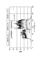
- FIG. 5 is a graph obtained by extracting the luminance value of the broken line portion in the image of FIG.
- FIG. 6 is an image of a hot-dip galvanized steel sheet with and without a chemical conversion treatment film taken by using a light receiving camera when the light intensity signal is standardized.
- FIG. 4 is an image of a hot-dip galvanized steel sheet with and without a chemical conversion coating film taken using a light receiving camera.
- FIG. 5 is a graph obtained by extracting the luminance value of the broken line portion in the image of FIG.
- FIG. 6 is an image of a hot-dip
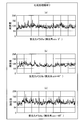
- FIG. 7 is a graph obtained by extracting the luminance value of the broken line portion in the images of FIGS. 6 (a) to 6 (c).
- FIG. 8 is a graph obtained by extracting the luminance value of the broken line portion in the images of FIGS. 6 (d) to 6 (f).
- FIG. 9 is a flowchart showing an example of control using the chemical conversion treatment membrane inspection method according to the first embodiment.
- FIG. 1 is a top view of the chemical conversion treatment membrane inspection device 1 according to the first embodiment.
- FIG. 2 is a side view of the chemical conversion treatment membrane inspection device 1 according to the first embodiment.
- the chemical conversion-treated film inspection apparatus 1 includes a linear diffusion light source 21, a polarizing plate 22, a light receiving unit 23, a signal processing unit 30, and the like, and is installed in a production line for hot-dip galvanized steel sheets and the like. ing.
- the surface of the steel sheet 10 that is moving due to the conveyed state is the surface to be inspected. Further, a chemical conversion treatment film is provided on the surface layer of the steel sheet 10.
- a linear diffusion light source 21 is arranged in the width direction of the steel plate 10 at a position above the steel plate 10 in the conveyed state in the direction of the arrow in the drawing.
- the linear diffusion light source 21 the light of the metal halide light source is guided by an optical fiber to an irradiation portion of rectangular light long in the width direction, and the light is projected from this irradiation portion. From this structure, the linear diffusion light source 21 can irradiate uniform light in the width direction of the steel plate 10.
- a fluorescent lamp can also be used as the linear diffusion light source 21. It is also possible to use a fiber light source in which the exit ends of the bundle fiber are aligned in a straight line. This is because the irradiation light from each fiber has a sufficient spread angle corresponding to the numerical aperture of the fiber, and the fiber light source in which the light sources are aligned is substantially a linear diffusion light source.
- the incident light L1 from the linear diffusion light source 21 with respect to the surface of the steel plate 10 is incident on the entire width of the surface of the steel plate 10 at an incident angle ⁇ 1 via the polarizing plate 22.
- the polarizing plate 22 is set to the detection angle ⁇ (azimuth angle), and the detection angle ⁇ is preferably in the range of 30 ° or more and 60 ° or less. Further, when the detection angle ⁇ is 45 °, the vertical wave and the horizontal wave are evenly included, which is more preferable.
- the detection angle is defined as a positive (plus) direction in which the normal to the surface to be inspected is 0 ° and the direction of rotation in the clockwise direction toward the surface to be inspected is 0 °.
- the light receiving unit 23 is configured to receive the reflected light reflected on the surface of the steel plate 10 by two or more light receiving cameras at two or more different detection angles ⁇ .
- the reflected light L2 reflected on the surface of the steel sheet 10 is incident on the light receiving portion 23 arranged in the specular reflection direction of the steel sheet.
- the light receiving unit 23 is composed of three light receiving means. For example, it is composed of light receiving cameras 25a, 25b, 25c composed of a linear array camera having detectors 24a, 24b, 24c in front of the lens.
- the light receiving camera 25a has an analyzer 24a on the front surface of the lens
- the light receiving camera 25b has an analyzer 24b on the front surface of the lens
- the light receiving camera 25c has an analyzer 24c on the front surface of the lens.
- the light receiving cameras 25a, 25b, 25c having the detectors 24a, 24b, 24c correspond to the light receiving means.
- the detector 24a is set with the detection angle ⁇ a
- the detector 24b is set with the detection angle ⁇ b
- the detector 24c is set with the detection angle ⁇ c.
- the detection angles ⁇ a, ⁇ b, and ⁇ c are preferably in the range of ⁇ 5 ° or more to 5 ° or less, 35 ° or more to 45 ° or less, and ⁇ 50 ° or more to ⁇ 40 ° or less, respectively.
- the optical axes of the light receiving cameras 25a, 25b, and 25c are installed so as to be parallel to each other.
- the pixels of the light receiving cameras 25a, 25b, and 25c have a one-to-one correspondence with each other in the same field of view size, which is preferable.
- the installation positions of the light receiving cameras 25a, 25b, and 25c are different with respect to the width direction of the steel plate 10, even if the same area is photographed, the coordinates of each pixel in each light receiving camera may be different. There is (hereinafter, also referred to as "field of view shift").
- Such a deviation in the field of view of the light receiving cameras 25a, 25b, 25c can be solved by correcting the deviation in the field of view by the signal processing unit 30.
- a two-dimensional CCD camera can be used instead of the linear array camera.
- a scanning photodetector that combines a single photodetector with a galvano mirror or polygon mirror.
- the light intensity of the reflected light L2 received by the light receiving cameras 25a, 25b, 25c is converted into light intensity signals Ia, Ib, Ic.
- the light intensity signals Ia, Ib, and Ic are transmitted to the signal processing unit 30 in response to the trigger signal created according to the distance traveled by the steel plate 10.
- the light intensity signals Ia, Ib, and Ic are image signals representing images of the surface of the steel sheet 10, respectively.
- the image signal on the surface of the steel plate 10 is a two-dimensional image signal representing a two-dimensional image. Therefore, in the present embodiment, the light intensity of the received reflected light L2 is converted into light intensity signals Ia, Ib, and Ic for each pixel of one line in the width direction of the steel plate 10.
- FIG. 3 is a block diagram showing a schematic configuration of the signal processing unit 30.
- the signal processing unit 30 includes signal preprocessing units 31a, 31b, 31c, memories 32a, 32b, 32c, representative value calculation units 33a, 33b, 33c, representative value comparison unit 34, which is a comparison determination unit, and output unit 35.
- signal preprocessing units 31a, 31b, 31c, memories 32a, 32b, 32c, representative value calculation units 33a, 33b, 33c, representative value comparison unit 34 which is a comparison determination unit, and output unit 35.
- the signal preprocessing units 31a, 31b, 31c, the memories 32a, 32b, 32c and the representative value calculation units 33a, 33b, 33c are provided for each light receiving means.
- the light receiving camera 25a, the signal preprocessing unit 31a, the memory 32a, and the representative value calculation unit 33a are connected in this order, and then connected to the representative value comparison unit 34.
- the light receiving camera 25b, the signal preprocessing unit 31b, the memory 32b, and the representative value calculation unit 33b are connected in this order, and then connected to the representative value comparison unit 34.
- the light receiving camera 25c, the signal preprocessing unit 31c, the memory 32c, and the representative value calculation unit 33c are connected in this order, and then connected to the representative value comparison unit 34.
- the signal preprocessing units 31a, 31b, 31c acquire the light intensity signals Ia, Ib, Ic output from the light receiving cameras 25a, 25b, 25c for each light receiving means. After that, the signal preprocessing units 31a, 31b, 31c perform various signal preprocessing on the light intensity signals Ia, Ib, Ic acquired from the light receiving cameras 25a, 25b, 25c.
- the gains of the light intensity signals Ia, Ib, Ic are adjusted for the luminance correction, and the intensity of the light intensity signals Ia, Ib, Ic is adjusted. No standardization process is performed to keep the feature values obtained from.
- the gain indicates "how many times the light intensity signal is multiplied" in order to make the feature value obtained from the intensity of the light intensity signal (that is, the image signal) constant.
- the characteristic value of the image signal in the present embodiment is obtained for each light receiving means from the intensity of the image signal.
- the characteristic values of the light intensity signals Ia, Ib, Ic are obtained for each light receiving means from the intensity of the light intensity signals Ia, Ib, Ic (that is, the image signal).
- outliers may occur when defects occur in the area under test.
- the deviation of the visual field of the light receiving cameras 25a, 25b, 25c is corrected.
- the edge position is detected and corresponds to the outside of the edge of the steel plate 10.
- the two-dimensional image region is set as the non-inspection target region, and the internal region of the steel sheet 10 with the edge position as the boundary is set as the inspection target region.
- the memories 32a, 32b, 32c store the light intensity signals Ia, Ib, Ic preprocessed by the signal preprocessing units 31a, 31b, 31c.
- the representative value calculation unit 33a, 33b, 33c calculates the representative values of the light intensity signals Ia, Ib, Ic from the light intensity signals Ia, Ib, Ic stored in the memories 32a, 32b, 32c for each light receiving means. ..
- a representative value for example, it is preferable to use the average value of the luminance distribution of the measured region set in the signal preprocessing. However, outliers may occur when defects occur in the area under test. In this case, it is more preferable to use the median value of the luminance distribution in the area to be measured or the mode value of the luminance distribution in the area to be measured as a representative value. When the median or mode is used, the influence of defects that occur in the area under test can be excluded.
- the area to be measured for calculating the feature value or the representative value in the area to be inspected is approximately the entire width in the width direction of the area to be inspected, and the length range of the steel sheet 10 predetermined in the steel sheet transport direction.
- the width direction is expressed as almost the entire width, but in reality, the vicinity of the edge of the steel sheet 10 which is the surface to be inspected is called a dead zone because it is easily affected by the warp of the steel sheet 10. For example, the inside in the width direction from the edge. An unused area that is not used for the calculation of about 10 mm may be provided.
- the representative value of the light intensity signal and the characteristic value of the light intensity signal may be the same or different.
- the mode value of the luminance distribution is set as the feature value of the light intensity signal
- the average value of the luminance distribution, the median luminance distribution, or the mode value of the same luminance distribution is set as the representative value of the luminance signal. Either of the above may be selected.
- two or more may be selected from the average value of the luminance distribution, the median luminance distribution, or the mode value of the same luminance distribution.
- the representative value comparison unit 34 determines the presence or absence of the chemical conversion treatment film from each representative value calculated for each light receiving means by the representative value calculation units 33a, 33b, 33c. For example, the representative values of the light intensity signals Ia, Ib, and Ic obtained for each of the light receiving cameras 25a, 25b, and 25c are compared, and when the comparison result falls within a predetermined range, the chemical conversion treatment film is used. Judge that there is no. An example of the comparison method will be described in detail later.
- the output unit 35 outputs the determination result of the presence / absence of the chemical conversion processing film in the representative value comparison unit 34 to the determination result display unit 40 provided outside the signal processing unit 30.
- the determination result display unit 40 displays the determination result of the presence or absence of the chemical conversion treatment film.
- the determination result of the presence or absence of the chemical conversion treatment film is combined with the determination result from a defect meter, a hole meter, a width meter, etc. provided on the production line separately from the chemical conversion treatment film inspection device 1. May be displayed.
- the defect meter and the hole meter are measuring instruments provided with a light source and a camera for detecting defects that may occur on the surface of the steel plate 10.
- the determination result is output from the output unit 35 to a computer higher than the chemical conversion treatment film inspection device 1 and managed. It doesn't matter.
- the signal preprocessing units 31a, 31b, 31c and the memories 32a, 32b, 32c are image signal acquisition means
- the representative value calculation units 33a, 33b, 33c are representative value calculation means
- the representative value comparison unit. 34 corresponds to the determination means.
- the light receiving cameras 25a, 25b, and 25c have been described as dedicated light receiving cameras included in the chemical conversion film inspection device 1, but the present invention is not limited to this.
- the signal of the light receiving camera provided in the existing defect meter on the production line may be branched and used in the chemical conversion film inspection device 1. In that case, it is not necessary to separately provide a light receiving camera for the defect meter and the chemical conversion treatment film inspection device 1, and the device configuration of the chemical conversion treatment film inspection device 1 can be realized compactly and inexpensively.
- FIG. 4 is an image of a hot-dip galvanized steel sheet with and without a chemical conversion treatment film taken during transportation using the chemical conversion treatment film inspection device 1 of FIGS. 1 and 3.
- the conditions at the time of shooting are as follows.
- a linear array camera was used as the light receiving cameras 25a, 25b, and 25c.
- the incident angle ⁇ 1 with respect to the total width of the plated steel sheet in the conveyed state is set to 60 °
- the detection angle ⁇ of the polarizing plate 22 is set to 45 °.
- the detection angle ⁇ a of the detector 24a is 0 °
- the detection angle ⁇ b of the detector 24b is 40 °.
- the detection angle ⁇ c of the photon 24c is set to ⁇ 45 °, respectively.
- FIG. 4A is an image of the hot-dip galvanized steel sheet taken by a light receiving camera 25a at an detection angle ⁇ a of 0 °.
- FIG. 4B is an image of the hot-dip galvanized steel sheet photographed by a light receiving camera 25b at a detection angle ⁇ b of 40 °.
- FIG. 4C is an image of the hot-dip galvanized steel sheet photographed by a light receiving camera 25c at a detection angle ⁇ c of ⁇ 45 °.
- FIG. 5 is a graph obtained by extracting the luminance value of the broken line portion in each of the images of FIGS. 4 (a), 4 (b) and 4 (c). Specifically, the graph in FIG.
- the detection angle ⁇ a is 0 ° is a graph obtained by extracting the luminance value of the broken line portion in FIG. 4A.
- the graph in FIG. 5 in which the detection angle ⁇ b is 45 ° is a graph obtained by extracting the luminance value of the broken line portion in FIG. 4 (b).
- the graph in FIG. 5 in which the detection angle ⁇ c is ⁇ 45 ° is a graph obtained by extracting the luminance value of the broken line portion in FIG. 4 (c).
- Table 1 shows the calculation results of the average value of the luminance distribution, the median luminance distribution, and the mode value of the luminance distribution as representative values of the light intensity signals Ia, Ib, and Ic.
- the representative values of the light intensity signals Ia, Ib, and Ic correspond to the light receiving cameras 25a, 25b, and 25c from which the respective light intensity signals Ia, Ib, and Ic are output, and the light receiving cameras 25a, It is also called a representative value of 25b and 25c.
- the light reception is better with or without the chemical-treated film than with the chemical-treated film.
- the representative value of the camera 25a is high, the representative value of the light receiving camera 25b is low, and the representative value of the light receiving camera 25c is high. From this, it can be seen that any of the average value of the luminance distribution, the median luminance distribution, and the mode value of the luminance distribution can be used as the representative value.
- the comparison of the representative values in the representative value comparison unit 34 for example, among the representative values of the three light receiving cameras 25a, 25b, and 25c, two representative values of the light receiving cameras measured at different detection angles ⁇ are selected. , The ratio of the two selected representative values can be calculated and the calculated ratio can be used. Specifically, the ratio between the representative value of the light receiving camera 25a and the representative value of the light receiving camera 25b, or the ratio of the representative value of the light receiving camera 25b and the representative value of the light receiving camera 25c is used.
- Table 2 shows the calculation results of the ratio between the representative value of the light receiving camera 25a and the representative value of the light receiving camera 25b, and the ratio of the representative value of the light receiving camera 25b and the representative value of the light receiving camera 25c.
- the ratio is calculated using the average value shown in Table 1.
- the ratio of the representative value of the light receiving camera 25a and the representative value of the light receiving camera 25b is used as an index for comparing the representative values, if the ratio value is smaller than a certain threshold value, "there is a chemical conversion treatment film", and the ratio is If the value is equal to or greater than the threshold value, it is determined that there is no chemical conversion treatment film.
- the threshold value is set in advance from the average value with and without the chemical conversion treatment film, and can be set to 2.6 in this case, for example. By this treatment, it is possible to determine the presence or absence of the chemical conversion treatment film.
- the ratio of the representative value of the light receiving camera 25b and the representative value of the light receiving camera 25c is used as an index for comparing the representative values, if the ratio value is equal to or higher than a certain threshold value, "there is a chemical conversion treatment film", and the ratio is If the value is smaller than the threshold value, it is determined that there is no chemical conversion treatment film.
- the threshold value is determined by the average value with and without the chemical conversion treatment film, and can be set to 0.2 in this case, for example. By this treatment, it is possible to determine the presence or absence of the chemical conversion treatment film.
- a method of using a defect meter for determining the presence or absence of the chemical conversion treatment film can be considered. ..
- a defect meter is applied to a light intensity signal output from a camera in order to remove the influence of deterioration of a light source and a difference in reflectance of a steel plate.
- Normalization processing to adjust the gain is performed. Therefore, if the chemical conversion treatment film is not formed over the entire width of the steel sheet and several meters in the transport direction, the brightness distribution changes in a range wider than the field of view of the camera. Therefore, by performing the standardization processing, the field of view of the camera It becomes impossible to distinguish the difference in reflectance depending on the presence or absence of the chemical conversion treatment film in the range.
- FIG. 6 is an image of a hot-dip galvanized steel sheet with and without a chemical conversion treatment film when the light intensity signals Ia, Ib, and Ic are standardized.
- the chemical conversion treatment membrane inspection apparatus 1 is used under the same conditions as in the above case except that there is a standardization treatment. In the standardization process, the average value of the luminance distribution was used as the feature value of the light intensity signals Ia, Ib, and Ic.
- FIG. 6A is an image of a hot-dip galvanized steel sheet having a chemical conversion treatment film taken by a light receiving camera 25a at an detection angle ⁇ a of 0 °.
- FIG. 6B is an image of a hot-dip galvanized steel sheet having a chemical conversion treatment film taken by a light receiving camera 25b at a detection angle ⁇ b of 40 °.
- FIG. 6C is an image of a hot-dip galvanized steel sheet having a chemical conversion treatment film taken by a light receiving camera 25c at an detection angle of ⁇ 45 °.
- FIG. 6D is an image of a hot-dip galvanized steel sheet without a chemical conversion treatment film taken by a light receiving camera 25a at an detection angle ⁇ a of 0 °.
- FIG. 6 (e) is an image of a hot-dip galvanized steel sheet without a chemical conversion coating film taken by a light receiving camera 25b at an detection angle ⁇ b of 40 °.
- FIG. 6 (f) is an image of a hot-dip galvanized steel sheet without a chemical conversion coating film taken by a light receiving camera 25c at an detection angle ⁇ c of ⁇ 45 °.
- FIG. 7 is a graph obtained by extracting the luminance value of the broken line portion in the images of FIGS. 6 (a) to 6 (c).
- FIG. 7A is a graph obtained by extracting the luminance value of the broken line portion of FIG. 6A.
- FIG. 7B is a graph obtained by extracting the luminance value of the broken line portion of FIG. 6B.
- FIG. 7 (c) is a graph obtained by extracting the luminance value of the broken line portion of FIG. 6 (c).
- FIG. 8 is a graph obtained by extracting the luminance value of the broken line portion in the images of FIGS. 6 (d) to 6 (f).
- FIG. 8A is a graph obtained by extracting the luminance value of the broken line portion of FIG. 6D.
- FIG. 8B is a graph obtained by extracting the luminance value of the broken line portion of FIG. 6E.
- FIG. 8 (c) is a graph obtained by extracting the luminance value of the broken line portion of FIG. 6 (f).
- Table 3 shows the calculation results of the average value of the luminance distribution, the median luminance distribution, and the mode value of the luminance distribution as representative values of the standardized light intensity signals Ia, Ib, and Ic. It is a thing.
- any of the average value of the luminance distribution, the median value of the luminance distribution, and the mode value of the luminance distribution is used as the representative value, as compared with the case with the chemical conversion treatment film. Without the chemical conversion treatment film, the representative values of the light receiving cameras 25a, 25b, and 25c are high.
- Table 4 shows the ratio of the representative value of the light receiving camera 25a to the representative value of the light receiving camera 25b and the ratio of the representative value of the light receiving camera 25b to the representative value of the light receiving camera 25c when the standardization process is performed. The calculation result is shown. In Table 4, the ratio is calculated using the average value of the luminance distribution shown in Table 3.
- the ratio of the representative value of the light receiving camera 25a to the representative value of the light receiving camera 25b is larger in the average value of the brightness distribution and the median value of the brightness distribution in the case without the chemical conversion treatment film than in the case with the chemical conversion treatment film. Therefore, in the mode of the brightness distribution, the value without the chemical conversion coating film is smaller than that without the chemical conversion treatment film. Further, the ratio of the representative value of the light receiving camera 25b to the representative value of the light receiving camera 25c is smaller in the average value of the brightness distribution and the median value of the brightness distribution in the case without the chemical conversion treatment film than in the case with the chemical conversion treatment film. In the mode of the brightness distribution, the value without the chemical conversion coating film is larger than that with the chemical conversion treatment film.
- both the ratio of the representative value of the light receiving camera 25a to the representative value of the light receiving camera 25b and the ratio of the representative value of the light receiving camera 25b to the representative value of the light receiving camera 25c are both the chemical conversion film.
- the difference in the ratio value between with and without the chemical conversion film is small.
- the average brightness distribution is represented as a representative value of the light intensity signals output from two or more light receiving cameras due to the difference in the amount of reflected light at two or more different detection angles.
- FIG. 9 is a flowchart showing an example of the chemical conversion treatment membrane inspection method according to the first embodiment.
- the chemical conversion treatment film inspection method used in the chemical conversion treatment film inspection apparatus 1 includes an incident step, a light receiving step, a signal preprocessing step, a representative value calculation step, and a determination step.
- the surface of the steel plate 10 which is the surface to be inspected is irradiated with polarized light (incident light L1) from the linear diffusion light source 21. That is, in the incident step, polarized light is incident on the surface to be inspected (step S1).
- the reflected light L2 reflected on the surface of the steel plate 10 is received by each of the light receiving cameras 25a, 25b, and 25c.
- detectors 24a, 24b, 24c are provided for each light receiving camera.
- the detection angle ⁇ a of the detector 24a, the detection angle ⁇ b of the detector 24b, and the detection angle ⁇ c of the detector 24c are selected from two or more types. In this embodiment, they are all different as an example. That is, light is received at three different detection angles (step S2).
- the signal preprocessing units 31a, 31b, 31c are light intensity which is an image signal representing an image of the surface of the steel plate 10 from the reflected light L2 received by the light receiving cameras 25a, 25b, 25c.
- Acquire signals Ia, Ib, Ic that is, this signal preprocessing step includes an image signal acquisition step.
- the acquired light intensity signals Ia, Ib, Ic are subjected to signal preprocessing such as correction of the deviation of the visual field of the light receiving cameras 25a, 25b, 25c and edge detection of the steel plate 10.
- Step S3 standardization processing for adjusting the gains of the light intensity signals Ia, Ib, and Ic and making the feature values of the light intensity signals Ia, Ib, and Ic constant is not performed for the luminance correction (Ste S3).
- This standardization process corresponds to the "gain adjustment step" in the second embodiment.
- the inspection target area and the non-inspection target area are set as described above.
- the light intensity signals Ia, Ib, Ic preprocessed by the signal preprocessing units 31a, 31b, 31c and the setting result of the inspection target area or the non-inspection target area are stored in the memories 32a, 32b, 32c.
- the representative value calculation unit 33a, 33b, 33c calculate the representative values of the light intensity signals Ia, Ib, and Ic (step S4).
- the representative values of the light intensity signals Ia, Ib, and Ic are specifically the average value of the luminance distribution because the influence of the non-stationary portion generated in the measured region can be excluded. preferable.
- the representative value comparison unit 34 determines the presence or absence of the chemical conversion treatment film on the surface of the steel sheet 10 by using the representative values for each light receiving means calculated by the representative value calculation units 33a, 33b, 33c. (Step S5).
- An example of the determination method in step S5 is as follows.
- the representative value comparison unit 34 selects two representative values of the light receiving cameras measured at different detection angles ⁇ from the representative values of the three light receiving cameras 25a, 25b, and 25c. Next, the representative value comparison unit 34 calculates the ratio of the two selected representative values.
- the representative value comparison unit 34 determines that the chemical conversion treatment film is absent or present when the calculated ratio of the representative values falls within a predetermined range.
- the determination result in the representative value comparison unit 34 is output to the determination result display unit 40 via the output unit 35, and the determination result is displayed in the determination result display unit 40 (step S6).
- the determination result display unit 40 may display that there is no chemical conversion treatment film only when it is determined that there is no chemical conversion treatment film. Further, the determination result display unit 40 may display the presence or absence of the chemical conversion treatment film both when it is determined that the chemical conversion treatment film is present and when it is determined that the chemical conversion treatment film is not present. ..
- the standardization process for making the feature value of the image signal constant is not performed for the luminance correction, and the representative value of the luminance distribution is not performed. Is obtained for each of the light receiving cameras 25a, 25b, and 25c and used for the determination, so that the apparatus configuration is inexpensive and simple, and the presence or absence of the chemical conversion treatment film is automatically determined while the steel plate 10 is being conveyed. be able to. As a result, it is possible to suppress the cost increase.
- the gains of the light intensity signals Ia, Ib, Ic are adjusted for the luminance correction, and the gains are obtained from the intensity of the light intensity signals Ia, Ib, Ic. Performs standardization processing to keep the feature values to be constant. Further, in the second embodiment, the gains of the light intensity signals Ia, Ib, and Ic adjusted for this standardization process are used as representative values. Except for these two points, the presence or absence of the chemical conversion treatment film is determined by the same procedure as the flowchart shown in FIG. 9 of the first embodiment. Also in the second embodiment, the definitions and specific contents of the “gain”, the “feature value of the image signal” and the “measured region” are the same as those in the first embodiment described above.
- the signal preprocessing units 31a, 31b, 31c perform standardization processing for luminance correction as one of the signal preprocessing.
- the gains of the light receiving cameras 25a, 25b, and 25c that have been adjusted are passed to the representative value calculation units 33a, 33b, and 33c via the memories 32a, 32b, and 32c for each light receiving means.
- the representative value calculation units 33a, 33b, 33c use the gain of the received light receiving camera as a representative value of the light intensity signals Ia, Ib, Ic.
- the representative value comparison unit 34 determines the presence or absence of the chemical conversion treatment film by using the gain of each light receiving camera as the representative value of the light intensity signal by the representative value calculation units 33a, 33b, 33c.
- the functions of each part other than the above description are the same as those of the chemical conversion treatment membrane inspection apparatus 1 according to the first embodiment.
- step S3 in FIG. 9 standardization processing is performed for luminance correction after the image signal acquisition step in the signal preprocessing step.
- the signal preprocessing units 31a, 31b, 31c adjust the gains of the light intensity signals Ia, Ib, Ic so that the characteristic values of the acquired light intensity signals Ia, Ib, Ic are constant.
- the step of performing this normalization process is referred to as a gain adjustment step. From step S4 in FIG. 9, the gains of the light intensity signals Ia, Ib, and Ic are treated as the representative values of the light intensity signals Ia, Ib, and Ic.
- Each step treatment other than the above description is the same as the chemical conversion treatment membrane inspection method according to the first embodiment.
- step S5 An example of the determination step (step S5) when each gain of the light receiving camera is used will be described.
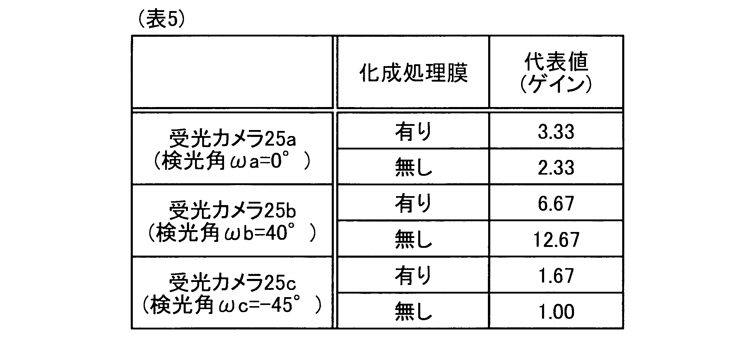
- Table 5 shows the gains indicating how many times the light intensity signals Ia, Ib, and Ic are multiplied when the standardization process of FIG. 6 is performed as typical values of the light intensity signals Ia, Ib, and Ic. ..
- the average value of the luminance distribution was used as the feature value of the light intensity signals Ia, Ib, and Ic.
- the representative values of the light intensity signals Ia, Ib, and Ic correspond to the light receiving cameras 25a, 25b, and 25c from which the respective light intensity signals Ia, Ib, and Ic are output, and the light receiving cameras 25a, It is also called a representative value of 25b and 25c.
- the representative value of the light receiving camera 25a is higher, the representative value of the light receiving camera 25b is lower, and the light receiving camera 25c is lower than that with the chemical conversion treatment film. It can be seen that the representative value is high. That is, as shown in Table 1 of the first embodiment, the tendency is the same as when the average value of the luminance distribution, the median luminance distribution, and the mode value of the luminance distribution are used as representative values. You can see that.
- the above gain is used as the representative value
- the comparison of the representative value by the representative value comparison unit 34 is performed by the ratio of the representative value of the light receiving camera 25a to the representative value of the light receiving camera 25b, or the light receiving camera. This is performed using the ratio of the representative value of 25c to the representative value of the light receiving camera 25b.
- Table 6 shows the ratio of the representative value of the light receiving camera 25a to the representative value of the light receiving camera 25b and the ratio of the representative value of the light receiving camera 25b to the representative value of the light receiving camera 25c when the gain is used as the representative value. The calculation result of is shown. In Table 6, the ratio is calculated using the gains shown in Table 5.
- the ratio value is smaller than a certain threshold value, " If there is a chemical conversion treatment film and the ratio value is equal to or greater than the threshold value, it is determined that there is no chemical conversion treatment film.
- the threshold value is set in advance from the average value with and without the chemical conversion treatment film, and can be set to 3.7 in this case, for example. By this treatment, it is possible to determine the presence or absence of the chemical conversion treatment film.
- the ratio value is equal to or higher than a certain threshold value
- “chemical conversion treatment” is performed. If there is a film and the ratio value is smaller than the threshold value, it is determined that there is no chemical conversion treatment film.
- the threshold value is set in advance from the average value with and without the chemical conversion treatment film, and can be set to 0.3 in this case, for example. By this treatment, it is possible to determine the presence or absence of the chemical conversion treatment film.
- the ratio of the representative values it is possible to determine the presence or absence of the chemical conversion treatment film on the surface of the steel sheet 10 if one set is used. Further, it is more preferable to take two or more sets because the determination can be performed more accurately.
- the light receiving cameras 25a, 25b, and 25c are described as dedicated light receiving cameras included in the chemical conversion film inspection device 1, but the present invention is not limited to this.
- the signal of the light receiving camera provided in the existing defect meter on the production line may be branched and used in the chemical conversion film inspection device 1. In that case, it is not necessary to separately provide a light receiving camera for the defect meter and the chemical conversion treatment film inspection device 1, and the device configuration of the chemical conversion treatment film inspection device 1 can be realized compactly and inexpensively.
- the chemical conversion-treated film inspection device 1 and the chemical conversion-treated film inspection method according to the second embodiment do not perform the standardization process for making the feature value of the image signal constant for the purpose of luminance correction.
- the gain of the light receiving camera obtained at the time of this standardization processing as a representative value for each of the light receiving cameras 25a, 25b, and 25c, the device configuration is inexpensive and simple, and the steel plate 10 is conveyed.
- the presence or absence of a chemical conversion treatment film can be automatically determined inside. As a result, it is possible to suppress the cost increase.
- the present invention is applied as an inspection device constituting a surface-treated steel sheet manufacturing facility, and is provided on the surface of a surface-treated steel sheet manufactured by a known or existing manufacturing facility by the chemical conversion film inspection device 1 according to the present invention.
- the chemical conversion treatment membrane may be inspected.
- the present invention may be applied as an inspection step included in a method for producing a surface-treated steel sheet, and a chemical conversion-treated film of a surface-treated steel sheet produced in a known or existing manufacturing step may be inspected. According to such a steel material manufacturing facility and a steel material manufacturing method, a surface-treated steel sheet can be manufactured with a high yield.
- the present invention may be applied to the quality control method of the surface-treated steel sheet, and the quality control of the surface-treated steel sheet may be performed by inspecting the chemical conversion-treated film provided on the surface of the surface-treated steel sheet.
- the presence or absence of a chemical conversion-treated film on the surface-treated steel sheet can be determined in the inspection step, and the quality control of the surface-treated steel sheet can be performed from the determination result obtained in the inspection step.
- results are obtained regarding the presence or absence of a chemical conversion treatment film on the surface-treated steel sheet.
- the subsequent quality control step it is determined whether or not the manufactured surface-treated steel sheet meets the predetermined criteria based on the result regarding the presence or absence of the chemical conversion-treated film of the surface-treated steel sheet obtained by the inspection step. Control the quality of steel materials. According to such a quality control method for steel materials, high quality steel materials can be provided.
- a chemical conversion-treated membrane inspection method and a chemical conversion-treated membrane inspection apparatus capable of determining the presence or absence of a chemical conversion-treated membrane on the surface to be inspected while the steel sheet is being conveyed are provided. Can be provided. Further, according to the present invention, in order to suppress the cost increase, it is possible to determine the presence or absence of the chemical conversion-treated film on the surface to be inspected while the surface-treated steel sheet is being conveyed, and improve the manufacturing yield of the surface-treated steel sheet. It is possible to provide a method for manufacturing a surface-treated steel sheet, a method for quality control of a surface-treated steel sheet, and a manufacturing facility for a surface-treated steel sheet.
Landscapes
- Engineering & Computer Science (AREA)
- Textile Engineering (AREA)
- Physics & Mathematics (AREA)
- Health & Medical Sciences (AREA)
- Life Sciences & Earth Sciences (AREA)
- Chemical & Material Sciences (AREA)
- Analytical Chemistry (AREA)
- Biochemistry (AREA)
- General Health & Medical Sciences (AREA)
- General Physics & Mathematics (AREA)
- Immunology (AREA)
- Pathology (AREA)
- Investigating Materials By The Use Of Optical Means Adapted For Particular Applications (AREA)
Abstract
Description
以下に、本発明に係る化成処理膜の検査方法及び化成処理膜検査装置の実施形態1について説明する。なお、本実施形態により本発明が限定されるものではない。


以下に、本発明に係る化成処理膜の検査方法及び化成処理膜検査装置の実施形態2について説明する。なお、実施形態2において実施形態1と共通する部分についての説明は省略する。

10 鋼板
21 線状拡散光源
22 偏光板
23 受光部
24a,24b,24c 検光子
25a,25b,25c 受光カメラ
30 信号処理部
31a,31b,31c 信号前処理部
32a,32b,32c メモリ
33a,33b,33c 代表値計算部
34 代表値比較部
35 出力部
40 判定結果表示部
Claims (6)
- 被検査面に偏光を入射させる入射ステップと、
前記入射された偏光が前記被検査面で反射した反射光を、2種類以上の異なる検光角で2つ以上の受光手段によりそれぞれ受光する受光ステップと、
前記受光手段で受光された前記反射光から、前記被検査面の像を表す像信号を、受光手段ごとに取得する像信号取得ステップと、
前記像信号から、各像信号の代表値を前記受光手段ごとに計算する代表値計算ステップと、
前記受光手段ごとに算出された前記代表値から、前記被検査面の化成処理膜の有無を判定する判定ステップと、
を含み、
前記像信号取得ステップと前記代表値計算ステップとの間に、前記像信号の強度から求められる前記像信号の特徴値が一定になるように、前記像信号のゲインを前記受光手段ごとに調整するゲイン調整ステップを行わない場合には、前記代表値計算ステップでは、前記代表値を前記像信号の強度から求める処理を行い、
前記像信号取得ステップと前記代表値計算ステップとの間に、前記ゲイン調整ステップを行う場合には、前記代表値計算ステップでは、前記代表値を前記ゲインから求める処理を行う、化成処理膜検査方法。 - 請求項1に記載の化成処理膜検査方法において、
前記判定ステップは、
前記代表値の中から異なる検光角を持つ前記受光手段における代表値を選び、選ばれた前記代表値から代表値の比を計算し、前記代表値の比から前記被検査面の化成処理膜の有無を判定する化成処理膜検査方法。 - 偏光を被検査面に照射する光源と、
前記照射された偏光が前記被検査面で反射した反射光を、2種類以上の異なる検光角でそれぞれ受光する2つ以上の受光手段と、
各受光手段で受光された各反射光から、前記被検査面の像を表す像信号を、前記受光手段ごとに取得する像信号取得手段と、
前記像信号から、各像信号の代表値を前記受光手段ごとに計算する代表値計算手段と、
前記受光手段ごとに算出された前記代表値から、前記被検査面の化成処理膜の有無を判定する判定手段と、
を備え、
前記像信号取得手段が、前記像信号の強度から求められる前記像信号の特徴値が一定になるように、前記像信号のゲインを前記受光手段ごとに調整を行わない場合には、前記代表値計算手段は、前記代表値を前記像信号の強度から求め、
前記像信号取得手段が、前記像信号の強度から求められる前記像信号の特徴値が一定になるように、前記像信号のゲインを前記受光手段ごとに調整を行う場合には、前記代表値計算手段は、前記代表値を前記ゲインから求める、化成処理膜検査装置。 - 表面処理鋼板の製造ステップと、
請求項1または2に記載の化成処理膜検査方法によって、前記製造ステップにおいて製造された表面処理鋼板の化成処理膜を検査する検査ステップと、
を含む、表面処理鋼板の製造方法。 - 請求項1または2に記載の化成処理膜検査方法によって、表面処理鋼板の化成処理膜を検査する検査ステップと、
前記検査ステップにより得られた検査結果から、前記表面処理鋼板の品質管理を行う品質管理ステップと、
を含む、表面処理鋼板の品質管理方法。 - 表面処理鋼板を製造するための製造設備と、
前記製造設備により製造された表面処理鋼板の化成処理膜を検査する請求項3に記載の化成処理膜検査装置と、
を備えた、表面処理鋼板の製造設備。
Priority Applications (3)
| Application Number | Priority Date | Filing Date | Title |
|---|---|---|---|
| JP2020552427A JP7074202B2 (ja) | 2019-03-08 | 2020-01-28 | 化成処理膜検査方法、化成処理膜検査装置、表面処理鋼板の製造方法、表面処理鋼板の品質管理方法及び表面処理鋼板の製造設備 |
| CN202080019379.4A CN113544495B (zh) | 2019-03-08 | 2020-01-28 | 化学转化处理膜检查方法、化学转化处理膜检查装置、表面处理钢板的制造方法、品质管理方法以及制造设备 |
| MX2021010733A MX2021010733A (es) | 2019-03-08 | 2020-01-28 | Metodo de inspeccion de pelicula quimicamente transformada, dispositivo de inspeccion de peliculas quimicamente transformadas, metodo de fabricacion de laminas de acero con tratamiento superficial, metodo de gestion de la calidad de la lamina de acero con tratamiento superficial, y equipos de fabricacion de lamina de 5 acero con tratamiento superficial. |
Applications Claiming Priority (2)
| Application Number | Priority Date | Filing Date | Title |
|---|---|---|---|
| JP2019043065 | 2019-03-08 | ||
| JP2019-043065 | 2019-03-08 |
Publications (1)
| Publication Number | Publication Date |
|---|---|
| WO2020183958A1 true WO2020183958A1 (ja) | 2020-09-17 |
Family
ID=72426716
Family Applications (1)
| Application Number | Title | Priority Date | Filing Date |
|---|---|---|---|
| PCT/JP2020/003028 Ceased WO2020183958A1 (ja) | 2019-03-08 | 2020-01-28 | 化成処理膜検査方法、化成処理膜検査装置、表面処理鋼板の製造方法、表面処理鋼板の品質管理方法及び表面処理鋼板の製造設備 |
Country Status (4)
| Country | Link |
|---|---|
| JP (1) | JP7074202B2 (ja) |
| CN (1) | CN113544495B (ja) |
| MX (1) | MX2021010733A (ja) |
| WO (1) | WO2020183958A1 (ja) |
Cited By (1)
| Publication number | Priority date | Publication date | Assignee | Title |
|---|---|---|---|---|
| CN113281341A (zh) * | 2021-04-19 | 2021-08-20 | 唐山学院 | 热镀锌带钢的双传感器表面质量检测系统的检测优化方法 |
Citations (6)
| Publication number | Priority date | Publication date | Assignee | Title |
|---|---|---|---|---|
| WO1992014119A1 (fr) * | 1991-01-30 | 1992-08-20 | Nkk Corporation | Ellipsometre et procede de controle d'epaisseur de revetement a l'aide de celui-ci |
| JPH0854353A (ja) * | 1994-06-08 | 1996-02-27 | Kawasaki Steel Corp | 印刷状態監視方法及び装置 |
| JPH11183398A (ja) * | 1997-12-25 | 1999-07-09 | Nkk Corp | 表面疵検査装置及びその方法 |
| US20030230720A1 (en) * | 2002-06-13 | 2003-12-18 | Shelley Paul H. | Method of measuring chromated conversion coating amount using infrared absorbance |
| JP2005221391A (ja) * | 2004-02-06 | 2005-08-18 | Jfe Steel Kk | 表面疵検査装置 |
| JP2012063275A (ja) * | 2010-09-16 | 2012-03-29 | Toyota Motor Corp | 車両鋼板における化成被覆率の簡易計測方法及びその装置 |
Family Cites Families (13)
| Publication number | Priority date | Publication date | Assignee | Title |
|---|---|---|---|---|
| JPH09127012A (ja) * | 1995-10-27 | 1997-05-16 | Nkk Corp | 表面疵の検出方法およびその装置 |
| CN100367027C (zh) * | 1995-10-27 | 2008-02-06 | 杰富意钢铁株式会社 | 表面缺陷的检查装置和方法 |
| JP3882302B2 (ja) * | 1997-12-25 | 2007-02-14 | Jfeスチール株式会社 | 表面疵検査装置及びその方法 |
| JP3446008B2 (ja) * | 1998-08-25 | 2003-09-16 | Jfeスチール株式会社 | 表面検査装置 |
| JP3995579B2 (ja) * | 2002-10-18 | 2007-10-24 | 大日本スクリーン製造株式会社 | 膜厚測定装置および反射率測定装置 |
| JP2006214935A (ja) * | 2005-02-04 | 2006-08-17 | Omron Corp | 薄膜検査装置および薄膜検査方法 |
| JP2007093340A (ja) * | 2005-09-28 | 2007-04-12 | Toyota Motor Corp | 塗装検査装置及び塗装検査方法 |
| JP4822468B2 (ja) * | 2010-03-19 | 2011-11-24 | レーザーテック株式会社 | 欠陥検査装置、欠陥検査方法、及びパターン基板の製造方法 |
| JP5422462B2 (ja) * | 2010-03-30 | 2014-02-19 | 富士フイルム株式会社 | 表面検査装置及び方法 |
| JP2014178249A (ja) * | 2013-03-15 | 2014-09-25 | Sumitomo Electric Ind Ltd | フィルム製造方法、フィルム製造プロセスモニタ装置及びフィルム検査方法 |
| ES2942266T3 (es) * | 2013-12-27 | 2023-05-31 | Jfe Steel Corp | Método de detección de defectos de superficie y dispositivo de detección de defectos de superficie |
| CN107533012B (zh) * | 2015-03-31 | 2019-07-19 | 日铁日新制钢株式会社 | 熔融镀覆钢板的表面缺陷检查装置及表面缺陷检查方法 |
| KR20180052089A (ko) * | 2016-11-09 | 2018-05-17 | 가부시키가이샤 한도오따이 에네루기 켄큐쇼 | 전자 기기의 동작 방법 |
-
2020
- 2020-01-28 WO PCT/JP2020/003028 patent/WO2020183958A1/ja not_active Ceased
- 2020-01-28 CN CN202080019379.4A patent/CN113544495B/zh active Active
- 2020-01-28 MX MX2021010733A patent/MX2021010733A/es unknown
- 2020-01-28 JP JP2020552427A patent/JP7074202B2/ja active Active
Patent Citations (6)
| Publication number | Priority date | Publication date | Assignee | Title |
|---|---|---|---|---|
| WO1992014119A1 (fr) * | 1991-01-30 | 1992-08-20 | Nkk Corporation | Ellipsometre et procede de controle d'epaisseur de revetement a l'aide de celui-ci |
| JPH0854353A (ja) * | 1994-06-08 | 1996-02-27 | Kawasaki Steel Corp | 印刷状態監視方法及び装置 |
| JPH11183398A (ja) * | 1997-12-25 | 1999-07-09 | Nkk Corp | 表面疵検査装置及びその方法 |
| US20030230720A1 (en) * | 2002-06-13 | 2003-12-18 | Shelley Paul H. | Method of measuring chromated conversion coating amount using infrared absorbance |
| JP2005221391A (ja) * | 2004-02-06 | 2005-08-18 | Jfe Steel Kk | 表面疵検査装置 |
| JP2012063275A (ja) * | 2010-09-16 | 2012-03-29 | Toyota Motor Corp | 車両鋼板における化成被覆率の簡易計測方法及びその装置 |
Cited By (1)
| Publication number | Priority date | Publication date | Assignee | Title |
|---|---|---|---|---|
| CN113281341A (zh) * | 2021-04-19 | 2021-08-20 | 唐山学院 | 热镀锌带钢的双传感器表面质量检测系统的检测优化方法 |
Also Published As
| Publication number | Publication date |
|---|---|
| CN113544495A (zh) | 2021-10-22 |
| JP7074202B2 (ja) | 2022-05-24 |
| JPWO2020183958A1 (ja) | 2021-04-08 |
| CN113544495B (zh) | 2024-10-29 |
| MX2021010733A (es) | 2021-09-28 |
Similar Documents
| Publication | Publication Date | Title |
|---|---|---|
| CN101568796B (zh) | 膜厚计测方法及其装置、以及薄膜设备的制造系统 | |
| JP5842373B2 (ja) | 表面欠陥検出方法、および表面欠陥検出装置 | |
| JPH08292156A (ja) | 表面被覆膜の局所欠陥を認識し、評価する認識および評価方法 | |
| JP5104004B2 (ja) | 表面欠陥検査装置および表面欠陥検査方法 | |
| JP6515348B2 (ja) | 表面検査装置用校正板及び表面検査装置の校正方法 | |
| CN100367027C (zh) | 表面缺陷的检查装置和方法 | |
| JP7074202B2 (ja) | 化成処理膜検査方法、化成処理膜検査装置、表面処理鋼板の製造方法、表面処理鋼板の品質管理方法及び表面処理鋼板の製造設備 | |
| JP6969500B2 (ja) | ダル仕上げ材表面の良否判定方法及び良否判定装置 | |
| US9091633B2 (en) | Apparatus and method for locating the centre of a beam profile | |
| KR20120104944A (ko) | 막 두께 불균일 검사 장치 및 방법 | |
| JPH03252512A (ja) | 油膜または塗膜のオンライン測定法およびその装置 | |
| JP3446008B2 (ja) | 表面検査装置 | |
| JP3826578B2 (ja) | 表面検査装置 | |
| TWI697663B (zh) | 透過使用紫外線之雷射結晶設備的雲紋量化系統及透過使用紫外線之雷射結晶設備的雲紋量化方法 | |
| JP2002333310A (ja) | 塗油量分布測定装置及び塗油量分布測定方法 | |
| JP2000019064A (ja) | フィルム評価方法およびフィルム評価装置 | |
| JPH09178666A (ja) | 表面検査装置 | |
| CN117288757A (zh) | 一种缺陷检测装置及缺陷检测方法 | |
| JP4549838B2 (ja) | 光沢度測定方法および装置 | |
| JP3716650B2 (ja) | 表面疵検査装置 | |
| JPH1172317A (ja) | スパングルサイズ測定装置 | |
| JP2009229174A (ja) | 表面検査装置および方法 | |
| JP3257552B2 (ja) | 表面疵検出装置 | |
| JP3063523B2 (ja) | 表面疵の検出方法およびその装置 | |
| JP5768349B2 (ja) | スリット光輝度分布設計方法および光切断凹凸疵検出装置 |
Legal Events
| Date | Code | Title | Description |
|---|---|---|---|
| ENP | Entry into the national phase |
Ref document number: 2020552427 Country of ref document: JP Kind code of ref document: A |
|
| 121 | Ep: the epo has been informed by wipo that ep was designated in this application |
Ref document number: 20769924 Country of ref document: EP Kind code of ref document: A1 |
|
| WWE | Wipo information: entry into national phase |
Ref document number: MX/A/2021/010733 Country of ref document: MX |
|
| NENP | Non-entry into the national phase |
Ref country code: DE |
|
| WWP | Wipo information: published in national office |
Ref document number: MX/A/2021/010733 Country of ref document: MX |
|
| 122 | Ep: pct application non-entry in european phase |
Ref document number: 20769924 Country of ref document: EP Kind code of ref document: A1 |
|
| WWG | Wipo information: grant in national office |
Ref document number: MX/A/2021/010733 Country of ref document: MX |