WO2020175559A1 - 液晶配向剤、液晶配向膜及びそれを用いた液晶表示素子 - Google Patents

液晶配向剤、液晶配向膜及びそれを用いた液晶表示素子 Download PDF

Info

Publication number
WO2020175559A1
WO2020175559A1 PCT/JP2020/007779 JP2020007779W WO2020175559A1 WO 2020175559 A1 WO2020175559 A1 WO 2020175559A1 JP 2020007779 W JP2020007779 W JP 2020007779W WO 2020175559 A1 WO2020175559 A1 WO 2020175559A1
Authority
WO
WIPO (PCT)
Prior art keywords
liquid crystal
group
formula
represented
aligning agent
Prior art date
Legal status (The legal status is an assumption and is not a legal conclusion. Google has not performed a legal analysis and makes no representation as to the accuracy of the status listed.)
Ceased
Application number
PCT/JP2020/007779
Other languages
English (en)
French (fr)
Inventor
石川 和典
達哉 名木
春鎬 金
Current Assignee (The listed assignees may be inaccurate. Google has not performed a legal analysis and makes no representation or warranty as to the accuracy of the list.)
Nissan Chemical Corp
Original Assignee
Nissan Chemical Corp
Priority date (The priority date is an assumption and is not a legal conclusion. Google has not performed a legal analysis and makes no representation as to the accuracy of the date listed.)
Filing date
Publication date
Application filed by Nissan Chemical Corp filed Critical Nissan Chemical Corp
Priority to CN202311448039.5A priority Critical patent/CN117487569A/zh
Priority to KR1020217025366A priority patent/KR102845629B1/ko
Priority to KR1020247025890A priority patent/KR102845630B1/ko
Priority to CN202080013962.4A priority patent/CN113423765B/zh
Priority to JP2021502321A priority patent/JP7447889B2/ja
Publication of WO2020175559A1 publication Critical patent/WO2020175559A1/ja
Anticipated expiration legal-status Critical
Priority to JP2024016380A priority patent/JP7626264B2/ja
Priority to JP2025007124A priority patent/JP7700975B2/ja
Priority to JP2025095803A priority patent/JP2025122253A/ja
Ceased legal-status Critical Current

Links

Classifications

    • CCHEMISTRY; METALLURGY
    • C09DYES; PAINTS; POLISHES; NATURAL RESINS; ADHESIVES; COMPOSITIONS NOT OTHERWISE PROVIDED FOR; APPLICATIONS OF MATERIALS NOT OTHERWISE PROVIDED FOR
    • C09KMATERIALS FOR MISCELLANEOUS APPLICATIONS, NOT PROVIDED FOR ELSEWHERE
    • C09K19/00Liquid crystal materials
    • C09K19/52Liquid crystal materials characterised by components which are not liquid crystals, e.g. additives with special physical aspect: solvents, solid particles
    • C09K19/54Additives having no specific mesophase characterised by their chemical composition
    • C09K19/56Aligning agents
    • CCHEMISTRY; METALLURGY
    • C08ORGANIC MACROMOLECULAR COMPOUNDS; THEIR PREPARATION OR CHEMICAL WORKING-UP; COMPOSITIONS BASED THEREON
    • C08GMACROMOLECULAR COMPOUNDS OBTAINED OTHERWISE THAN BY REACTIONS ONLY INVOLVING UNSATURATED CARBON-TO-CARBON BONDS
    • C08G73/00Macromolecular compounds obtained by reactions forming a linkage containing nitrogen with or without oxygen or carbon in the main chain of the macromolecule, not provided for in groups C08G12/00 - C08G71/00
    • C08G73/06Polycondensates having nitrogen-containing heterocyclic rings in the main chain of the macromolecule
    • C08G73/10Polyimides; Polyester-imides; Polyamide-imides; Polyamide acids or similar polyimide precursors
    • C08G73/1075Partially aromatic polyimides
    • C08G73/1078Partially aromatic polyimides wholly aromatic in the diamino moiety
    • CCHEMISTRY; METALLURGY
    • C08ORGANIC MACROMOLECULAR COMPOUNDS; THEIR PREPARATION OR CHEMICAL WORKING-UP; COMPOSITIONS BASED THEREON
    • C08GMACROMOLECULAR COMPOUNDS OBTAINED OTHERWISE THAN BY REACTIONS ONLY INVOLVING UNSATURATED CARBON-TO-CARBON BONDS
    • C08G73/00Macromolecular compounds obtained by reactions forming a linkage containing nitrogen with or without oxygen or carbon in the main chain of the macromolecule, not provided for in groups C08G12/00 - C08G71/00
    • C08G73/06Polycondensates having nitrogen-containing heterocyclic rings in the main chain of the macromolecule
    • C08G73/10Polyimides; Polyester-imides; Polyamide-imides; Polyamide acids or similar polyimide precursors
    • CCHEMISTRY; METALLURGY
    • C08ORGANIC MACROMOLECULAR COMPOUNDS; THEIR PREPARATION OR CHEMICAL WORKING-UP; COMPOSITIONS BASED THEREON
    • C08GMACROMOLECULAR COMPOUNDS OBTAINED OTHERWISE THAN BY REACTIONS ONLY INVOLVING UNSATURATED CARBON-TO-CARBON BONDS
    • C08G73/00Macromolecular compounds obtained by reactions forming a linkage containing nitrogen with or without oxygen or carbon in the main chain of the macromolecule, not provided for in groups C08G12/00 - C08G71/00
    • C08G73/06Polycondensates having nitrogen-containing heterocyclic rings in the main chain of the macromolecule
    • C08G73/10Polyimides; Polyester-imides; Polyamide-imides; Polyamide acids or similar polyimide precursors
    • C08G73/1003Preparatory processes
    • C08G73/1007Preparatory processes from tetracarboxylic acids or derivatives and diamines
    • CCHEMISTRY; METALLURGY
    • C08ORGANIC MACROMOLECULAR COMPOUNDS; THEIR PREPARATION OR CHEMICAL WORKING-UP; COMPOSITIONS BASED THEREON
    • C08GMACROMOLECULAR COMPOUNDS OBTAINED OTHERWISE THAN BY REACTIONS ONLY INVOLVING UNSATURATED CARBON-TO-CARBON BONDS
    • C08G73/00Macromolecular compounds obtained by reactions forming a linkage containing nitrogen with or without oxygen or carbon in the main chain of the macromolecule, not provided for in groups C08G12/00 - C08G71/00
    • C08G73/06Polycondensates having nitrogen-containing heterocyclic rings in the main chain of the macromolecule
    • C08G73/10Polyimides; Polyester-imides; Polyamide-imides; Polyamide acids or similar polyimide precursors
    • C08G73/1042Copolyimides derived from at least two different tetracarboxylic compounds or two different diamino compounds
    • CCHEMISTRY; METALLURGY
    • C08ORGANIC MACROMOLECULAR COMPOUNDS; THEIR PREPARATION OR CHEMICAL WORKING-UP; COMPOSITIONS BASED THEREON
    • C08JWORKING-UP; GENERAL PROCESSES OF COMPOUNDING; AFTER-TREATMENT NOT COVERED BY SUBCLASSES C08B, C08C, C08F, C08G or C08H
    • C08J5/00Manufacture of articles or shaped materials containing macromolecular substances
    • C08J5/18Manufacture of films or sheets
    • CCHEMISTRY; METALLURGY
    • C09DYES; PAINTS; POLISHES; NATURAL RESINS; ADHESIVES; COMPOSITIONS NOT OTHERWISE PROVIDED FOR; APPLICATIONS OF MATERIALS NOT OTHERWISE PROVIDED FOR
    • C09KMATERIALS FOR MISCELLANEOUS APPLICATIONS, NOT PROVIDED FOR ELSEWHERE
    • C09K19/00Liquid crystal materials
    • C09K19/52Liquid crystal materials characterised by components which are not liquid crystals, e.g. additives with special physical aspect: solvents, solid particles
    • C09K19/54Additives having no specific mesophase characterised by their chemical composition
    • C09K19/542Macromolecular compounds
    • GPHYSICS
    • G02OPTICS
    • G02FOPTICAL DEVICES OR ARRANGEMENTS FOR THE CONTROL OF LIGHT BY MODIFICATION OF THE OPTICAL PROPERTIES OF THE MEDIA OF THE ELEMENTS INVOLVED THEREIN; NON-LINEAR OPTICS; FREQUENCY-CHANGING OF LIGHT; OPTICAL LOGIC ELEMENTS; OPTICAL ANALOGUE/DIGITAL CONVERTERS
    • G02F1/00Devices or arrangements for the control of the intensity, colour, phase, polarisation or direction of light arriving from an independent light source, e.g. switching, gating or modulating; Non-linear optics
    • G02F1/01Devices or arrangements for the control of the intensity, colour, phase, polarisation or direction of light arriving from an independent light source, e.g. switching, gating or modulating; Non-linear optics for the control of the intensity, phase, polarisation or colour 
    • G02F1/13Devices or arrangements for the control of the intensity, colour, phase, polarisation or direction of light arriving from an independent light source, e.g. switching, gating or modulating; Non-linear optics for the control of the intensity, phase, polarisation or colour  based on liquid crystals, e.g. single liquid crystal display cells
    • G02F1/133Constructional arrangements; Operation of liquid crystal cells; Circuit arrangements
    • G02F1/1333Constructional arrangements; Manufacturing methods
    • G02F1/1337Surface-induced orientation of the liquid crystal molecules, e.g. by alignment layers
    • GPHYSICS
    • G02OPTICS
    • G02FOPTICAL DEVICES OR ARRANGEMENTS FOR THE CONTROL OF LIGHT BY MODIFICATION OF THE OPTICAL PROPERTIES OF THE MEDIA OF THE ELEMENTS INVOLVED THEREIN; NON-LINEAR OPTICS; FREQUENCY-CHANGING OF LIGHT; OPTICAL LOGIC ELEMENTS; OPTICAL ANALOGUE/DIGITAL CONVERTERS
    • G02F1/00Devices or arrangements for the control of the intensity, colour, phase, polarisation or direction of light arriving from an independent light source, e.g. switching, gating or modulating; Non-linear optics
    • G02F1/01Devices or arrangements for the control of the intensity, colour, phase, polarisation or direction of light arriving from an independent light source, e.g. switching, gating or modulating; Non-linear optics for the control of the intensity, phase, polarisation or colour 
    • G02F1/13Devices or arrangements for the control of the intensity, colour, phase, polarisation or direction of light arriving from an independent light source, e.g. switching, gating or modulating; Non-linear optics for the control of the intensity, phase, polarisation or colour  based on liquid crystals, e.g. single liquid crystal display cells
    • G02F1/133Constructional arrangements; Operation of liquid crystal cells; Circuit arrangements
    • G02F1/1333Constructional arrangements; Manufacturing methods
    • G02F1/1337Surface-induced orientation of the liquid crystal molecules, e.g. by alignment layers
    • G02F1/133711Surface-induced orientation of the liquid crystal molecules, e.g. by alignment layers by organic films, e.g. polymeric films
    • G02F1/133723Polyimide, polyamide-imide
    • CCHEMISTRY; METALLURGY
    • C08ORGANIC MACROMOLECULAR COMPOUNDS; THEIR PREPARATION OR CHEMICAL WORKING-UP; COMPOSITIONS BASED THEREON
    • C08JWORKING-UP; GENERAL PROCESSES OF COMPOUNDING; AFTER-TREATMENT NOT COVERED BY SUBCLASSES C08B, C08C, C08F, C08G or C08H
    • C08J2379/00Characterised by the use of macromolecular compounds obtained by reactions forming in the main chain of the macromolecule a linkage containing nitrogen with or without oxygen, or carbon only, not provided for in groups C08J2361/00 - C08J2377/00
    • C08J2379/04Polycondensates having nitrogen-containing heterocyclic rings in the main chain; Polyhydrazides; Polyamide acids or similar polyimide precursors
    • C08J2379/08Polyimides; Polyester-imides; Polyamide-imides; Polyamide acids or similar polyimide precursors

Definitions

  • Liquid crystal aligning agent Liquid crystal aligning agent, liquid crystal aligning film and liquid crystal display device using the same
  • the present invention relates to a liquid crystal aligning agent, a liquid crystal aligning film and a liquid crystal display device using the same.
  • a liquid crystal device includes, for example, a liquid crystal layer sandwiched between an element substrate and a color filter substrate, a pixel electrode and a common electrode that apply an electric field to the liquid crystal layer, an alignment film that controls the alignment of liquid crystal molecules in the liquid crystal layer, It is equipped with a thin film transistor, etc. that switches the electrical signals supplied to the pixel electrodes.
  • the liquid crystal molecules can be driven by vertical electric field methods such as the Ting method and the eight method, and method, (Fringe field switching) A horizontal electric field method such as a method is known.
  • a photoalignment method As a liquid crystal alignment treatment method that replaces the rubbing treatment, a photoalignment method is known, which imparts liquid crystal alignment ability by irradiating polarized radiation.
  • As liquid crystal alignment treatment by the photo-alignment method there have been proposed a photo-isomerization reaction, a photo-crosslinking reaction, and a photo-decomposition reaction (see Non-Patent Document 1 and Patent Document 1). ).
  • ⁇ 2020/175559 2 (: 170? 2020/007779
  • a liquid crystal alignment film which is a component of a liquid crystal display element, is a film for uniformly aligning liquid crystals, but various properties are required in addition to the alignment uniformity of liquid crystals. For example, charges are accumulated in the liquid crystal alignment film due to the voltage that drives the liquid crystal, and the afterimage or image sticking (hereinafter referred to as the residual aperture (hereinafter referred to as afterimage of 3)) affects the display, and the display quality of the liquid crystal display element is significantly degraded. Therefore, a liquid crystal aligning agent that overcomes these problems has been proposed (see Patent Document 2).
  • Patent Document 3 discloses a specific liquid crystal aligning agent.
  • Patent Document 4 discloses a liquid crystal aligner that maintains good liquid crystal orientation and has good adhesion to the sealant. ing.
  • Patent Document 1 Japanese Patent Laid-Open No. 9-2 9 7 3 13
  • Patent Document 2 International Publication No. 205/0 8 3 5 0 4 Panfret
  • Patent Document 3 International Publication No. 2 0 15/0 5 0 1 3 5 Panfret
  • Patent Document 4 International Publication No. 2 0 15/0 6 0 3 6 0 Pamphlet Non-Patent Document
  • Non-Patent Document 1 "Liquid Crystal Photo-Alignment Film” Kidowaki, Ichimura Functional Materials 199 9 Jan. Jan. V ⁇ ⁇ . 17, N 0. Overview
  • the present invention has been made in view of the above circumstances, and liquid crystal alignment film having good liquid crystal alignment property and good adhesiveness with a sealing agent, and adhesive property between liquid crystal alignment film and a sealing agent. It is a major object of the present invention to provide a liquid crystal aligning agent capable of obtaining a liquid crystal display device exhibiting good display quality because the frame can be narrowed because it is excellent.
  • the present inventor has conducted extensive studies and found that the above problems can be solved by using a liquid crystal aligning agent containing a polymer component having a specific repeating unit, and completed the present invention. Came to do.
  • the gist of the present invention is as follows.
  • monovalent organic group having from 1 to 6, or Ri phenyl group der may be the same or different, and at least one of them represents a group other than a hydrogen atom in the above definition.
  • the following formula (1 1) represents a divalent organic group having a partial structure represented by ⁇ 2020/175 559 4 (: 170? 2020/007779
  • (Say yes 2 is a tetravalent organic group having 5 or more-membered ring alicyclic structure.
  • the liquid crystal aligning film has good liquid crystal aligning property and good adhesiveness with the sealant, and the liquid crystal aligning film has good adhesiveness with the sealant. Since it is good, it is possible to further narrow the frame, and a liquid crystal display element having good display quality can be obtained.
  • the liquid crystal aligning agent of the present invention contains a polymer () having a repeating unit represented by the above formula (1), the above formula (2), the above formula (3) and the above formula (4). With such a structure, a liquid crystal alignment film with less generation of afterimage can be obtained, and a liquid crystal display device having excellent contrast can be obtained.
  • alkyl group having 1 to 6 carbon atoms in are a methyl group, an ethyl group, a propyl group, a propyl group, a 1-1 butyl group, a butyl group, a £-butyl group, a 1-butyl group. , —Pentyl group and the like.
  • alkenyl group having 2 to 6 carbon atoms include a vinyl group, a propenyl group, afugyl group and the like, and these may be linear or branched.
  • alkynyl group having 2 to 6 carbon atoms include an ethynyl group, a 1-propynyl group, a 2-propynyl group and the like. the above
  • Examples of the halogen atom in 4 include a fluorine atom, a chlorine atom, a bromine atom and an iodine atom.
  • Examples of the C 1-6 monovalent organic group containing a fluorine atom include a fluoromethyl group and a trifluoromethyl group. From the viewpoint of high photoreactivity, Is a hydrogen atom or a methyl group,
  • At least one of is a methyl group, and more preferably at least two of are a methyl group. More preferred is This is the case.
  • Specific examples of the monovalent organic group substituting any hydrogen atom on the benzene ring in the above formula (1 to 1) include a halogen atom, an alkyl group having 1 to 6 carbon atoms, and 2 to 2 carbon atoms. Examples thereof include an alkenyl group having 6 carbon atoms, an alkynyl group having 2 to 6 carbon atoms, and a monovalent organic group having 1 to 6 carbon atoms and containing a fluorine atom, and examples thereof include the structures exemplified in 1 to 4 above.
  • the polymer (8) has a repeating unit represented by the above formula (2) from the viewpoint of improving heat resistance.
  • the tetravalent organic group represented by formula (2) 2 is preferably a tetravalent organic group having a 5- to 8-membered alicyclic structure, and a 5- to 7-membered alicyclic structure. More preferably, it is a valent organic group.
  • the alicyclic structure to which the imido group is bonded is a polycyclic structure
  • the five-membered or more alicyclic structure means the atoms constituting the ring in each ring included in the polycyclic structure. It shows that all numbers are 5 or more.
  • the alicyclic structure may be bonded to at least one of the two imido groups, and may have a chain hydrocarbon structure or an aromatic ring structure together with the alicyclic structure.
  • Preferred examples of say yes 2 the following formula (say yes 2 - 1) - include tetravalent organic group represented by either Neu deviation - (1 2 say yes 2). ⁇ 2020/175 559 8 ⁇ (: 170? 2020/007779
  • the two of (2) to (4) of (2) to (2) of (2) Is more preferable.
  • Preferred specific examples of the second item in the above formula (2) are the same as the preferred specific examples of the second item in the above formula (1).
  • the polymer () is (3) the total of the repeating units represented by the above formula (1) and the repeating units represented by the above formula (2) is defined as all repeating units from the viewpoint of less afterimage.
  • the content is preferably 1 to 95 mol %, more preferably 5 to 90 mol %.
  • the ratio ((1): (2)) of the repeating unit represented by the above formula (1) and the repeating unit represented by the above formula (2), which the polymer () has, is 70:3.
  • ⁇ ⁇ 9 9: 1 is preferable, 7 5: 2 5 ⁇ 98: 2 is more preferable,
  • the polymer (8) is represented by the repeating unit represented by the above formula (3) and the above formula (4) from the viewpoint of enhancing the contrast and seal adhesion of the liquid crystal display device. ⁇ 2020/175 559 9 (: 170? 2020/007779
  • the polymer () is preferably (3) a total of repeating units represented by the above formula (3) and repeating units represented by the above formula (4), from the viewpoint of less afterimage, with respect to all repeating units. Is more preferably 5 to 99 mol %, and particularly preferably 10 to 95 mol %.
  • the ratio ((3):(4)) of the repeating unit represented by the above formula (3) and the repeating unit represented by the above formula (4), which the polymer () has, is 70:30 to It is preferably 99:1, more preferably 75:25 to 98:2, and even more preferably 80:20 to 97:3.
  • the polymer () has a repeating unit represented by the above formula (1) and the above formula (1)
  • the ratio ((1):(3)) to the repeating unit represented by 3) is preferably 1:9 9 to 99:1, more preferably 5:95 to 80:20, It is more preferably 10:90 to 70:30.
  • the ratio ((2): (4)) to the repeating unit represented by 4) is preferably 1:9 9 to 99:1, more preferably 5:95 to 80:20, It is more preferably 10:90 to 70:30.
  • the polymer (8) is the total of repeating units represented by the above formula (1), formula (2), formula (3) and formula (4) On the other hand, the content is preferably 6 to 100 mol %, and particularly preferably 15 to 100 mol %.
  • the polymer (8) is selected from the group consisting of repeating units represented by the following formula (5) and repeating units represented by the following formula (6). It may have at least one type of repeating unit selected. ⁇ 02020/175559 10 (: 17 2020 /007779
  • 5 , 5 and 6 are each independently represented by a divalent organic group having a partial structure represented by the following formula (“ _ 1) or the following formula (“ _2) Ru
  • X 6 in the formula (6) is Ru say yes 2 synonymous der of the formula (2).
  • any (_ 0 1 to 1 2 ) of _ 0 1 to 1 2 — is not adjacent to each other, 10 1, 100 1, 1, 100 1, 1 -, -N0 900 _ , _ ⁇ ⁇ ⁇ 9 _ , _ ⁇ 9 ⁇ ⁇ ⁇ 10 _ , _ ⁇ 9 ⁇ ⁇ ⁇ _ , or _ ⁇ ⁇ ⁇ 001 is a group that can be replaced.
  • ⁇ 9 and ⁇ 10 each independently represent a hydrogen atom or a monovalent organic group.
  • [ 5 ] and [ 6 ] include:
  • the polymer () further has the following formula: It may have at least one kind of repeating unit selected from the group consisting of the repeating unit represented by I — 8 — 1) and the repeating unit represented by (_ 1 ).
  • tetravalent organic group represented by the following formula (9) other tetravalent organic groups exemplified by say yes 2 in the formula (2), the following formula (X ⁇ - 1) ⁇ ( 1 _ 1 3)), a tetravalent organic group represented by any one of (1) to (3), a tetravalent organic group derived from an aromatic tetracarboxylic acid dianhydride, and the like.
  • the aromatic tetracarboxylic dianhydride that gives the tetravalent organic group of X ! is an acid obtained by intramolecular dehydration of a carboxyl group bonded to an aromatic ring such as a benzene ring or a naphthalene ring. It is a dianhydride.
  • a tetravalent organic group represented by either can be mentioned.
  • alkyl group having 1 to 5 carbon atoms include a methyl group, an ethyl group, a propyl group, a propyl group, a 1-1 _butyl group, a butyl group, a%-butyl group, I -Butyl group, clo-pentyl group and the like. From the viewpoint of ease of imidization by heating, Is preferably a hydrogen atom or a methyl group.
  • alkyl group having 1 to 10 carbon atoms having 8 ⁇ and 8 12 above include
  • alkenyl group having 8 to 12 carbon atoms and having 2 to 10 carbon atoms include vinyl group and propene group. ⁇ 2020/175559 17 ⁇ (: 170? 2020/007779 Ru group, Sanchezyl group, and the like, which may be linear or branched. Above / ⁇ ⁇ 2 of alkynyl group having 2 to 10 carbon atoms Specific examples include an ethynyl group, a 1-propynyl group, a 2-propynyl group and the like.
  • a substituent May have a substituent, and examples of the substituent include a halogen atom (fluorine atom, chlorine atom, bromine atom, iodine atom), a hydroxyl group, a cyano group, an alkoxy group and the like.
  • a halogen atom fluorine atom, chlorine atom, bromine atom, iodine atom
  • a hydroxyl group a cyano group
  • an alkoxy group and the like.
  • the ratio ((5):(6)) of the polymer containing the repeating unit represented by the above formula (5) and the repeating unit represented by the above formula (6) is 7
  • the ratio is preferably 0:30 to 99:1, more preferably 75:25 to 98:2, and even more preferably 80:20 to 97:3.
  • the polymer () has the repeating unit represented by the formula (5) and the formula (5)
  • the total of repeating units represented by 6) is preferably 1 to 40 mol%, more preferably 1 to 30 mol%, based on all the repeating units of the polymer (). It is preferably 5 to 30 mol %.
  • the total number of repeating units represented by the above formula (1), formula (2), formula (3) and formula (4) is 6 to 99 mol based on all the repeating units of the polymer (). %, more preferably 15 to 99 mol%,
  • the liquid crystal aligning agent of the present invention is a composition containing the polymer () and an organic solvent, and the polymer () having a different structure may contain two or more kinds. Further, the liquid crystal aligning agent of the present invention may contain a polymer other than the polymer () (hereinafter, also referred to as a second polymer) and various additives.
  • the content ratio of the polymer () to all the polymer components is preferably 5% by mass or more, and preferably 5 to 95% by mass. , And more preferably 10 to 90% by mass.
  • Examples of the second polymer include polyamic acid, polyimide, polyamic acid ester, polyester, polyamide, polyurea, and polyorganosiloxane. ⁇ 2020/175 559 18 ⁇ (: 170? 2020/007779
  • a polyamic acid obtained from a tetracarboxylic dianhydride component and a diamine component (hereinafter, also referred to as a second polyamic acid) is preferable as the second polymer.
  • the tetracarboxylic acid dianhydride component for obtaining the second polyamic acid a compound represented by the following formula (11) can be mentioned.
  • the tetracarboxylic acid dianhydride component may be composed of two or more kinds of compounds.
  • (81 1) and (81 2) are preferable from the viewpoint of further improving the photo-alignment property, and (81 4) is from the viewpoint of further improving the relaxation rate of accumulated charges.
  • (81-15) to (81-17) and the like are preferable from the viewpoint of further improving the liquid crystal orientation and the relaxation rate of accumulated charges.
  • the diamine component for obtaining the second polyamic acid can be appropriately determined according to the purpose, and for example, a diamine represented by the following formula (12) can be used.
  • ( 9 represents a divalent organic group.
  • the two 9 are each independently a hydrogen atom or an alkyl group having 1 to 5 carbon atoms, an alkenyl group having 2 to 5 carbon atoms, or 2 to 5 carbon atoms.
  • 5 is a alkynyl group.
  • eight 9 is a hydrogen atom or a methylation group.
  • the carbon atom 9 is a divalent organic group having a secondary or tertiary nitrogen atom, or
  • diamine represented by the formula (1 2) in the case where 9 is a divalent organic group having a secondary or tertiary nitrogen atom include any of the following (3) to ().
  • the diamine of the above is mentioned.
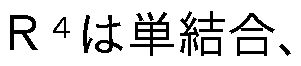
  • the two 2 are each independently a single bond or a group.
  • ! _, _ ⁇ (01 ⁇ 1 2) m ⁇ _, _ Rei_rei_1 ⁇ 1 to 1 _, and _1 ⁇ 11-1 Represents a divalent organic group selected from _ ((01, 01 represents an integer of 1 to 5), *1 represents a site bonded to the benzene ring in the formula (
  • a diamine having a carbazole structure described in ( ⁇ ) 0201 8/1 10354 preferably a diamine having a structure represented by the following formula ( ⁇ ).
  • X is a biphenyl ring or a fluorene ring.
  • is a benzene ring, a biphenyl ring, or a group selected from the group consisting of 11 and 11 represents a phenylene group. It is a divalent group represented by 10 1 to 1 2 —, — 30 2 — % — 0 (0 1 to 1 3 ) 2 — or 1 0 (0 3 ) 2 —.
  • 8 1 is 1 1 ⁇ 1 !--- ⁇ ⁇ 1 1 ⁇ 1 1 to 1 -, - ⁇ _1 ⁇ 1 2 alkylene group with carbon number 2-2 0 - at least _ one but one 1 ⁇ 1-hundred one 1-substituted group in the 1-, or an alkylene group having a carbon number of 2-2 0
  • 1 ⁇ 1 1 ⁇ 1 _, and at least _ of the other _ 0 1 ⁇ 1 2 — are 101, _ ⁇ —, 100 001, 1 [3 ⁇ 4 ⁇ 001 ([ 3 ⁇ 4 represents a hydrogen atom or a methyl group.),
  • Eighty- two represents a halogen atom, a hydroxy group, or an alkyl group or an alkoxy group having 1 to 5 carbon atoms (any hydrogen atom of the above alkyl group or alkoxy group may be substituted with a halogen atom).
  • 3 is an integer from 0 to 4, and when 3 is 2 or more, 8 2 may be the same or different.
  • 13 and ⁇ are integers of 1 or 2.
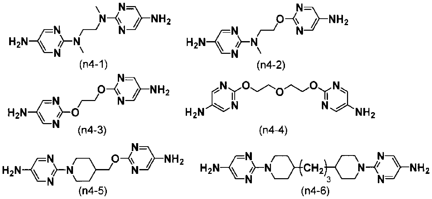
  • ⁇ 02020/175559 25 (: 17 2020/007779 is a diamine represented by any one of the following formulas (closure 3-1) to (n 3-7), the following formula (1 ⁇ 4-1) ⁇ Examples include diamines represented by any of (1 ⁇ 4-6).
  • a diamine having a carboxyl group (OO 1 to 1 group) or a hydroxyl group (O 1 to 1 group) can also be used. Specifically, 2,
  • benzyl alcohol 2,4-diaminobenzyl alcohol, 4,6-diaminoresorcinol, 2,4-diaminobenzoic acid, 2,5-diaminobenzoic acid or 3,5-diaminobenzoic acid.
  • 2,4-diaminobenzoic acid, 2,5-diaminobenzoic acid and 3,5-diaminobenzoic acid are preferable.
  • diamines represented by the following formulas [313-1] to [31 ⁇ -4], or diamines in which these amino groups are secondary amino groups can also be used.
  • 0 1 is a single bond, _ ⁇ 1 to 1 2 — , _ ⁇ 2 1 to 1 4 — , — 0 (01 to 1 3 )
  • ⁇ 2 represents a linear or branched aralkyl Killen group 5 1 carbon atoms, 5 represents an integer of 1 to 5.
  • 0 3 and 0 4 are each independently a single bond, Ten 2 1 - 1 4 -, -0 (Rei_1 ⁇ 1 3) 2 -
  • the diamine component for obtaining the second polyamic acid the diamine used for obtaining the polymer (8) or a known diamine can be used in addition to the above.
  • the diamine component for obtaining the second polyamic acid may be a combination of two or more kinds of diamines.
  • Polyamic acid ester, polyamic acid, and polyimide which are the polyimide precursors used in the present invention, are, for example, It can be produced by a known method such as that described in No. 7586.
  • the liquid crystal aligning agent of the present invention may contain the polymer () and, if desired, the second polymer, and in addition to these, other polymers.
  • Other polymers include polyamic acid, polyimide, polyamic acid ester, polyester, polyamide, polyurea, polyorganosiloxane, cellulose derivative, polyacetal, polystyrene or its derivative, poly(styrene-phenylmaleimide) derivative, poly( (Meth) acrylate etc. can be mentioned.
  • the liquid crystal aligning agent is used to prepare a liquid crystal aligning film, and takes the form of a coating liquid from the viewpoint of forming a uniform thin film.
  • the liquid crystal director of the present invention is also preferably a coating liquid containing the above-mentioned polymer component and an organic solvent.
  • the concentration (content) of the polymer in the liquid crystal aligning agent can be appropriately changed by setting the thickness of the coating film to be formed. From the viewpoint of forming a uniform and defect-free coating film, 1% by mass or more is preferable, and from the viewpoint of storage stability of the solution, 10% by mass or less is preferable. A particularly preferred polymer concentration is 2 to 8% by mass.
  • the organic solvent contained in the liquid crystal aligning agent is not particularly limited as long as it is a solvent in which the polymer component is uniformly dissolved (also referred to as a good solvent).
  • a solvent in which the polymer component is uniformly dissolved also referred to as a good solvent.
  • the good solvent is preferably 20 to 99 mass% of the entire solvent contained in the liquid crystal aligning agent, more preferably 20 to 90 mass%, and particularly preferably 30 to 80 mass%. Is.
  • the organic solvent contained in the liquid crystal aligning agent is, in addition to a good solvent, a solvent (also referred to as a poor solvent) that improves the coatability when applying the liquid crystal aligning agent and the surface smoothness of the coating film. It is preferable to use a mixed solvent used in combination. Specific examples of the poor solvent are shown below, but the invention is not limited to these examples.
  • diisopropyl ether diisoptyl ether, diisoptyl carbinol (2, 6-dimethyl-4-heptanol), ethylene glycol dimethyl ether, ethylene glycol dityl ether, ethylene glycol dibutyl ether.
  • diisoptyl carpinol propylene glycol monoptyl ether, propylene glycol diacetate, propylene glycol diethyl ether, dipropylene glycol monomethyl ether, and di propylene glycol dimethyl ether are preferred.
  • Ether 4-hydroxy_4-methyl-2-pentanone, ethylene glycol monoptyl ether, ethylene glycol monoptyl ether acetate, and diisobutyl ketone are preferred.
  • the amount of these poor solvents is preferably 1 to 80% by mass, more preferably 10 to 80% by mass, and particularly preferably 20 to 70% by mass, based on the whole solvent contained in the liquid crystal aligning agent.
  • the type and content of such a solvent are appropriately selected depending on the coating apparatus for the liquid crystal aligning agent, coating conditions, coating environment, and the like.
  • the liquid crystal aligning agent of the present invention may additionally contain components other than the polymer component and the organic solvent.
  • additional component include an adhesion aid for increasing the adhesion between the liquid crystal alignment film and the substrate and the adhesion between the liquid crystal alignment film and the sealing material, and a compound for increasing the strength of the liquid crystal alignment film (hereinafter referred to as crosslinking Also referred to as a polar compound.), a dielectric or a conductive substance for adjusting the dielectric constant or electric resistance of the liquid crystal alignment film.
  • crosslinkable compound examples include: oxiranyl group, oxetanyl group, protected isocyanate group, protected isothiocyanate group, oxazoline ring structure-containing group, and meldrumic acid, from the viewpoint of less afterimage generation and high effect of improving film strength.
  • ( 871 is a hydrogen atom, an alkyl group having 1 to 3 carbon atoms or Is.
  • [3 ⁇ 4 72 and [3 ⁇ 4 73 are each independently a hydrogen atom, an alkyl group having 1 to 3 carbon atoms or G*_CH 2 — ⁇ H]. * Indicates a bond. Represents an organic group having an aromatic ring and having a valence of 0. A door represents an integer from 0 to 4.
  • Specific examples of the compound having a protected isocyanate group include compounds having two or more protected isocyanate groups described in JP-A No. 2014-224978, [0046] to [0047], No. 4 1 598, which has three or more protected isocyanate groups described in [01 19] to [01 20] ⁇ 02020/175 559 32 (: 17 2020 /007779
  • Examples include compound. Of these, compounds represented by any of the following formulas (13-1) to (3-1) are preferable.
  • Specific examples of the compound having a group containing an oxazoline ring structure include the compounds containing two or more oxazoline structures described in [01 15] of Japanese Patent Laid-Open No. 2007-286597.
  • Examples thereof include compounds having two or more Meldrum's acid structures described in 2/09 1 088.
  • Specific examples of the compound having a cyclocarbonate group include the compounds described in ⁇ / ⁇ 201 1/1 55577.
  • Examples thereof include a methyl group, an ethyl group and a propyl group.
  • Examples thereof include a (01+11)-valent organic group having an aromatic hydrocarbon group bonded directly or via a linking group, and a (111+11)-valent group having an aromatic heterocycle.
  • the aromatic hydrocarbon group include benzene and naphthalene.
  • the aromatic heterocycle include a pyrrole ring, an imidazole ring, a pyrazole ring, a pyridine ring, a pyrimidine ring, a quinoline ring, an isoquinoline ring, a carbazole ring, a pyridazine ring, a pyrazine ring, a benzimidazole ring, a benzimidazole ring, and an indole.
  • linking group examples include an alkylene group having 1 to 10 carbon atoms, a group obtained by removing one hydrogen atom from the above alkylene group, a divalent or trivalent cyclohexane ring, and the like. Any hydrogen atom of the above alkylene group may be substituted with a fluorine atom or an organic group such as a trifluoromethyl group. Specific examples include the compounds described in ⁇ / ⁇ 201 0/074269. Preferred specific examples include any of the following formulas (6-1) to (6-9).
  • the above compound is an example of a crosslinkable compound, and is not limited to these.
  • components other than the above disclosed in [01 05] to [01 16] of ⁇ / ⁇ 201 5/060357 can be mentioned.
  • the liquid crystal display of the present invention ⁇ 2020/175 559 35 ⁇ (: 170? 2020/007779
  • Two or more kinds of the crosslinkable compounds contained in the stimulant may be combined.
  • the content of the crosslinkable compound is preferably 0.5 to 20 parts by mass with respect to 100 parts by mass of the polymer component contained in the liquid crystal aligning agent. From the viewpoint that the reaction proceeds and the intended effect is exhibited, and the generation of afterimage is small, it is more preferably from 1 to 15 parts by mass.
  • adhesion aid examples include, for example, 3-aminopropyltrimethoxysilane, 3-aminopropyltriethoxysilane, 3-aminopropylgetoxymethylsilane, 2-aminopropyltrimethoxysilane, 2-aminopropyltriethoxysilane, 1 ⁇ 1— (2-aminoethyl) 1-aminopropyltrimethoxysilane, 1 ⁇ !— (2-aminoethyl) 1 3-aminopropylmethyldimethoxysilane, 3-ureidopropyltrimethoxysilane, 3-ureidopropyltrie Toxylsilane, 1 ⁇ !—Ethoxycarbonyl-3-aminopropyl trimethyloxysilane, 1 ⁇ 1—Ethoxycarbonyl-3—aminopropyltrioxysilane, 1 ⁇ 1 _ Triethoxysilylpropyltriethylene triamine, 1 ⁇ 1 ⁇ 1
  • Examples include silane coupling agents such as 3-mercaptopropylmethyldimethoxysilane, 3-mercaptopropyltrimethoxysilane, and 3-isocyanatopropyltriethoxysilane.
  • the amount of these silane coupling agents used is preferably from 0.1 to 30 parts by mass with respect to 100 parts by mass of the polymer component contained in the liquid crystal aligning agent, from the viewpoint of less occurrence of afterimages. More preferably, it is 0.1 to 20 parts by mass.
  • the liquid crystal alignment film using the liquid crystal alignment agent of the present invention can be produced by the known method for obtaining a liquid crystal alignment film from the liquid crystal alignment agent using the liquid crystal alignment agent of the present invention.
  • the liquid crystal alignment film using the liquid crystal aligning agent of the present invention is more efficient by sequentially performing the following step (1), step (2), step (3), and preferably step (4) Can be manufactured in a simple manner.
  • the substrate to which the liquid crystal aligning agent is applied is not particularly limited as long as it is a highly transparent substrate, and a glass substrate, a silicon nitride substrate, a plastic substrate such as an acrylic substrate or a polycarbonate substrate, or the like can also be used. At that time, it is preferable to use a substrate on which electrodes for driving the liquid crystal are formed in order to simplify the process.
  • an opaque material such as a silicon wafer can be used for the substrate on one side, and in this case, a material that reflects light such as aluminum can also be used for the electrode.
  • the liquid crystal aligning agent is generally applied industrially by screen printing, offset printing, flexographic printing or ink jet method. That ⁇ 2020/175 559 37 ⁇ (: 170? 2020 /007779
  • coating methods include a dip method, a mouth coater method, a slit coater method, a spinner method or a spray method, and these may be used depending on the purpose.
  • Step (2) is a step of heating the coating film of the liquid crystal aligning agent obtained in step (1).
  • the solvent can be evaporated and the amic acid or amic acid ester in the polymer can be thermally imidized by a heating means such as an (infrared) type oven.
  • the drying and baking steps after applying the liquid crystal aligning agent can be performed at any temperature and time, and may be performed plural times.
  • the temperature at which the organic solvent of the liquid crystal aligning agent is removed can be, for example, 40 to 150 ° . From the viewpoint of shortening the process, it may be carried out at 40 to 120 ° .
  • the firing time is not particularly limited, but may be 1 to 10 minutes or 1 to 5 minutes.
  • the amic acid or amic acid ester in the polymer is subjected to thermal imidization, after the step of removing the above organic solvent, it is baked at , for example, 1 90 to 250 ° ⁇ or 200 to 240 ° ⁇ . be able to.
  • the firing time is not particularly limited, but may be 5 to 40 minutes or 5 to 30 minutes.
  • Step (3) is the step of irradiating the film obtained in step (2) with polarized ultraviolet light.
  • the wavelength of ultraviolet rays is 200 to 400 n And more preferably 200 ⁇ 300 n m.
  • the substrate coated with the liquid crystal alignment film may be irradiated with ultraviolet rays while being heated at 50 to 250 ° .
  • the dose of the above radiation is 1 to 10,000. Is preferred, 100 to 5, 0 Is more preferable.
  • the liquid crystal alignment film thus produced can stably align liquid crystal molecules in a certain direction.
  • the extinction ratio of linearly polarized ultraviolet light is preferably 10:1 or more, more preferably 20:1 or more. ⁇ 2020/175 559 38 ⁇ (: 170? 2020 /007779
  • Step (4) is a step of baking the film obtained in step (3) at a temperature of 100 ° C. or higher and higher than that in step (2).
  • Firing temperature, in 1 0 0 ° ⁇ As, and, higher than the firing temperature in step (2) is not particularly limited, but is preferably 1 5 0 to 3 0 0 ° ⁇ , 1 5 0-2 5 0° is more preferable, and 200 to 250° is further preferable.
  • the firing time is preferably 5 to 120 minutes, more preferably 5 to 60 minutes, and further preferably 5 to 30 minutes.
  • the thickness of the liquid crystal alignment film after firing is too thin, the reliability of the liquid crystal display element may decrease, so Is preferable, and 10 to 200 n is more preferable.
  • the obtained liquid crystal alignment film may be subjected to contact treatment with water and/or a solvent.
  • the solvent used in the above contact treatment is not particularly limited as long as it is a solvent that dissolves the decomposition product generated from the liquid crystal alignment film by irradiation with ultraviolet rays. Specific examples include water, methanol, ethanol, 2-propanol, acetone, methyl ethyl ketone, 1-methoxy_2-propanol, 1-methoxy-2-propanol acetate, butyl cellosolve, ethyl lactate, methyl lactate, diethyl.
  • Acetone alcohol, methyl 3-methoxypropionate, ethyl 3-ethoxypropionate, propyl acetate, butyl acetate, cyclohexyl acetate and the like can be mentioned.
  • water, 2-propanol, 1-methoxy-2-propanol or ethyl lactate is preferable from the viewpoint of versatility and solvent safety. More preferred is water, 1-methoxy-2-propanol or ethyl lactate.
  • Two or more kinds of solvents may be combined.
  • an immersing treatment or a spraying treatment (also referred to as a spraying treatment) can be mentioned.
  • the treatment time in these treatments is preferably 10 seconds to 1 hour from the viewpoint of efficiently dissolving the decomposition product generated from the liquid crystal alignment film by ultraviolet rays.
  • the solvent at the time of the contact treatment may be heated at room temperature or may be heated, but is preferably 10 to 80°C. Above all, 20 to 50°C is preferable.
  • ultrasonic treatment may be performed if necessary.
  • rinsing also referred to as rinsing
  • a low-boiling-point solvent such as water, methanol, ethanol, 2-propanol, acetone or methyl ethyl ketone
  • the firing temperature is preferably 150 to 300° C., preferably 180 to 250° C., and more preferably 200 to 230° C.
  • the firing time is preferably 10 seconds to 30 minutes, more preferably 1 to 10 minutes.
  • the liquid crystal alignment film of the present invention is suitable as a liquid crystal alignment film of a horizontal electric field type liquid crystal display device such as a PS system or a FFS system, and is particularly useful as a liquid crystal alignment film of a FFS system liquid crystal display device. is there.
  • a liquid crystal display device is obtained by preparing a liquid crystal cell by a known method after obtaining a substrate having a liquid crystal alignment film obtained from a liquid crystal aligning agent.
  • a liquid crystal display element having a passive matrix structure As an example of a method for manufacturing a liquid crystal cell, a liquid crystal display element having a passive matrix structure will be described as an example.
  • a liquid crystal display element having an active matrix structure in which a switching element such as TFT (Thin Fiber Transistor) is provided in each pixel portion that constitutes image display may be used.
  • TFT Thin Fiber Transistor
  • a transparent glass substrate is prepared, a common electrode is provided on one substrate, and a segment electrode is provided on the other substrate.
  • These electrodes can be ITO electrodes, for example, and are patterned to display a desired image.
  • an insulating film is provided on each substrate so as to cover the common electrode and the segment electrode.
  • the insulating film can be, for example, a S i 0 2 -T i O 2 film formed by a sol-gel method.
  • a liquid crystal alignment film is formed on each substrate, one substrate is overlaid with the other liquid crystal alignment film surface facing each other, and the periphery is bonded with a sealant. Spacers are usually added to the sealant to control the substrate gap. ⁇ 2020/175 559 40 ⁇ (: 170? 2020 /007779
  • the liquid crystal material is injected into the space surrounded by the two substrates and the sealing agent through the opening provided in the sealing agent, and then the opening is sealed with an adhesive.
  • a vacuum injection method may be used, or a method utilizing a capillary phenomenon in the air may be used.
  • the liquid crystal material either a positive type liquid crystal material or a negative type liquid crystal material may be used.
  • install the polarizing plate Specifically, a pair of polarizing plates are attached to the surfaces of the two substrates opposite to the liquid crystal layer.
  • the step (3) is carried out, so that the liquid crystal alignment film can be obtained in a smaller number of steps than in the past.
  • the liquid crystal aligning agent of the present invention is particularly preferably used in the method for producing a liquid crystal aligning film, which comprises the step of carrying out step (3) after removing the organic solvent at 40 to 150 ° in step (2). be able to.
  • liquid crystal aligning agent of the present invention it is possible to obtain a liquid crystal aligning film having a high seal adhesiveness with less generation of afterimages and 80 afterimages derived from the residual port 0.
  • liquid crystal display element which is excellent in contrast and which suppresses variations in brightness in the plane during black display, and a liquid crystal display element having good display quality is obtained.
  • 3-1 a compound represented by the following formula (3_1),
  • Polyimide powder 2 Into an IV! sample tube (IV! Sampling tube standard, ⁇ 5 (Kusano Scientific Co., Ltd.)) and add deuterated dimethyl sulfoxide. ⁇ .05% Ding 1 ⁇ /13 (Tetramethylsilane) mixed product) (0.53 1_) was added, and ultrasonic waves were applied to completely dissolve it. This solution was used to measure 50 protons 1 ⁇ /
  • the imidization rate is determined by using the proton derived from the structure that does not change before and after imidization as the reference proton, and the peak integrated value of this proton and 1 ⁇ 11 ⁇ 1 ⁇ of the amide acid appearing around 9.5 0 ⁇ 1 0.0. It was determined by the following formula using the integrated value of the proton peak derived from the group.
  • X is the proton peak integrated value derived from the 1 ⁇ 11 to 1 group of amide acid, so is the peak integrated value of the reference proton, and ⁇ is the amino acid in the case of polyamidic acid (imidization rate is 0%). This is the ratio of the number of standard protons to one 1 ⁇ 11 to 1 group proton of acid.
  • is poly ⁇ 2020/175 559 43 ⁇ (: 170? 2020 /007779
  • 0-8-1 is 2.059 (0. 0084 0101), and 081-1 is 4.1 69 ( 0.01 9601_Rei I) weighed, 1 ⁇ / 1? 88.6 9 by the addition of such feed the nitrogen but was stirred et al dissolved. While stirring this diamine solution Add 1 to 5.52 9 ( ⁇ 0.0246 ⁇ 101), and ⁇ 81 2 to ⁇ .359 ( ⁇ . 001 40 ⁇ 10 I), stir at 40° ⁇ for 24 hours, and mix with polyamic acid solution. (81) (Viscosity: 2 1 301 8 3) was obtained. ⁇ 2020/175 559 44 ⁇ (: 170? 2020 /007779
  • the resulting reaction solution was poured into 150O!I of methanol while stirring, the deposited precipitate was collected by filtration, and the same operation was repeated twice to wash the resin powder, and then at 60 ° C. By drying for 12 hours, a polyimide resin powder was obtained. The imidation ratio of this polyimide resin powder was 71%.
  • the obtained polyimide resin powder 3.609 Into an Erlenmeyer flask I, 26.49 of IV! was added so that the solid content concentration was 12%, and the mixture was stirred and dissolved at 70 ° ⁇ for 24 hours to obtain a polyimide solution (_ 1 _ I).
  • the values in parentheses in Table 1 are, for the tetracarboxylic acid component, the compounding ratio (mol part) of each compound to 100 mol parts of the total amount of the tetracarboxylic acid derivative used in the synthesis, and the diamine With regard to the components, the compounding ratio (mol part) of each compound to 100 mol parts of the total amount of diamine used in the synthesis is shown. For organic solvents, the compounding ratio (parts by mass) of each organic solvent to the total amount of 100 parts by mass of organic solvent contained in the polyamic acid solution or the polyimide solution is shown.
  • Examples 2 to 5 and Comparative Examples 2 and 3 were carried out in the same manner as Comparative Example 1 and Example 1 except that each polyimide solution, additive and organic solvent described in Table 2 below were used. Each liquid crystal aligning agent was obtained. The specifications of the obtained liquid crystal aligning agents are shown in Table 1 together with the liquid crystal aligning agents of Example 1 and Comparative Example 1.
  • the numerical value in parentheses represents the mixing ratio (mass %) of each component to 100 parts by mass of the total amount of the liquid crystal aligning agent.
  • a substrate with electrodes was prepared.
  • the board is 30 ⁇ 35 in size and has a thickness of 0.7. It is a glass substrate.
  • a first electrode is formed as a counter electrode, which is provided with a solid pattern and has a solid pattern. 1st layer ⁇ 2020/175 559 48 ⁇ (: 170? 2020/007779
  • a 3 1 1 ⁇ 1 (silicon nitride) film formed by the XX method is formed on the counter electrode of the eye.
  • the film thickness of the second layer 3 ⁇ 1 ⁇ 1 film is 5 0 0 n m, and functions as an interlayer insulating film.
  • a comb-teeth-shaped pixel electrode formed by patterning the 0st film is arranged as the 3rd layer. Form one pixel. The size of each pixel is Is.
  • the counter electrode of the first layer and the pixel electrode of the third layer are electrically insulated by the action of the 3rd 1 ⁇ ! film of the second layer.
  • the pixel electrode of the third layer has a comb-tooth shape formed by arranging a plurality of "dogleg” shaped electrode elements each having a bent central portion.
  • the width of each electrode element in the lateral direction is 30! and the spacing between the electrode elements is 60!.
  • the pixel electrode that forms each pixel is configured by arranging a plurality of curved "dogleg” shaped electrode elements in the central part, so the shape of each pixel is not rectangular, but is similar to that of the electrode element. It has a shape similar to the bold "dogleg” that bends at some parts.
  • Each pixel is divided into an upper part and a lower part with a central bent portion as a boundary, and has a first region on the upper side and a second region on the lower side of the bent portion.
  • each substrate with a liquid crystal alignment film having a film thickness of 100 n was baked for 30 minutes in a hot-air circulation type oven at 230 °C to obtain each substrate with a liquid crystal alignment film having a film thickness of 100 n.
  • the liquid crystal alignment agent prepared above was applied to a 30 ⁇ 40 substrate by spin coating. After drying for 2 minutes on a hot plate of 80 ° ⁇ , the coated surface is irradiated with 254 n of ultraviolet rays through a polarizing plate, and then heated in a hot air circulation oven at 230 ° ⁇ for 20 minutes. Firing was carried out for 1 minute to form a coating film having a film thickness of 100 nm. After preparing the two substrates thus obtained, applying a 4-bead spacer on the surface of the liquid crystal alignment film of one of the substrates, and then applying a sealant (XN-1500 ) Was added dropwise.
  • the overlapping width of the substrate is 1 Were pasted together so that At that time, the diameter of the sealant after bonding
  • the dropping amount of the sealing agent was adjusted so that After fixing the two bonded substrates with a clip, they were heat-cured at 150° for 1 hour to prepare a sample for evaluation of adhesion.
  • the liquid crystal aligning agent of the present invention is useful for forming a liquid crystal aligning film in a wide range of liquid crystal display devices such as a three-drive system and a three-drive system.

Landscapes

  • Chemical & Material Sciences (AREA)
  • Physics & Mathematics (AREA)
  • Organic Chemistry (AREA)
  • Health & Medical Sciences (AREA)
  • Chemical Kinetics & Catalysis (AREA)
  • Nonlinear Science (AREA)
  • Polymers & Plastics (AREA)
  • Medicinal Chemistry (AREA)
  • Crystallography & Structural Chemistry (AREA)
  • Engineering & Computer Science (AREA)
  • Mathematical Physics (AREA)
  • Optics & Photonics (AREA)
  • Spectroscopy & Molecular Physics (AREA)
  • General Physics & Mathematics (AREA)
  • Materials Engineering (AREA)
  • Manufacturing & Machinery (AREA)
  • Macromolecular Compounds Obtained By Forming Nitrogen-Containing Linkages In General (AREA)
  • Liquid Crystal (AREA)
  • Compositions Of Macromolecular Compounds (AREA)

Abstract

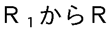
配向性が良好であるとともに、シール剤との密着性が良好な液晶配向膜を得ることができる液晶配向剤を提供する。 下記式(1)、式(2)、式(3)及び式(4)で表される繰り返し単位を有する重合体(A)を含有することを特徴とする液晶配向剤。(R1からR4は、それぞれ独立して、水素原子、ハロゲン原子、アルキル基等を表し、Y1は式(H)で表される部分構造を有する2価の有機基を表し、Q3は-(CH2)n-で表される構造であり、X2は、5員環以上の脂環構造を有する4価の有機基である。Y2は式(H)で表される部分構造を有する2価の有機基を表し、R31からR34は、上記R1からR4と同義であり、X4はX2と同義であり、Y3、Y4は式(I)で表される2価の有機基を表す。

Description

\¥0 2020/175559 1 ?<:17 2020 /007779 明 細 書
発明の名称 :
液晶配向剤、 液晶配向膜及びそれを用いた液晶表示素子
技術分野
[0001 ] 本発明は、 液晶配向剤、 液晶配向膜及びそれを用いた液晶表示素子に関す る。
背景技術
[0002] 従来から液晶装置は、 パーソナルコンピュータ、 携帯電話、 スマートフォ ン、 テレビジョン受像機等の表示部として幅広く用いられている。 液晶装置 は、 例えば、 素子基板とカラーフィルタ基板との間に挟持された液晶層、 液 晶層に電界を印加する画素電極及び共通電極、 液晶層の液晶分子の配向性を 制御する配向膜、 画素電極に供給される電気信号をスイツチングする薄膜卜 ランジスタ (丁 丁) 等を備えている。 液晶分子の駆動方式としては、 丁 方式、 八方式等の縦電界方式や、 I
Figure imgf000003_0001
方式、
Figure imgf000003_0002
(フリンジフィール ドスイツチング) 方式等の横電界方式が知られている。
[0003] 現在、 工業的に最も普及している液晶配向膜は、 電極基板上に形成された 、 ポリアミツク酸及び/又はこれをイミ ド化したポリイミ ドからなる膜の表 面を、 綿、 ナイロン、 ポリエステル等の布で一方向に擦る、 いわゆるラビン グ処理を行うことで作製されている。 ラビング処理は、 簡便で生産性に優れ た工業的に有用な方法である。 しかし、 液晶表示素子の高性能化、 高精細化 、 大型化に伴い、 ラビング処理で発生する配向膜の表面の傷、 発塵、 機械的 な力や静電気による影響、 更には、 配向処理面内の不均一性等の種々の問題 が明らかとなっている。 ラビング処理に代わる液晶配向処理方法としては、 偏光された放射線を照射することにより、 液晶配向能を付与する光配向法が 知られている。 光配向法による液晶配向処理は、 光異性化反応を利用したも の、 光架橋反応を利用したもの、 光分解反応を利用したもの等が提案されて いる (非特許文献 1、 特許文献 1参照) 。 〇 2020/175559 2 卩(:170? 2020 /007779
[0004] 液晶表示素子の構成部材である液晶配向膜は、 液晶を均一に配列させるた めの膜であるが、 液晶の配向均一性だけでなく種々の特性が必要とされる。 例えば、 液晶を駆動させる電圧によって液晶配向膜に電荷が蓄積し、 残像や 焼き付き (以下、 残留口(3由来の残像と称する。 ) として表示に影響を与え 、 液晶表示素子の表示品位を著しく低下させたりする問題点があるため、 こ れらの課題を克服する液晶配向剤が提案されている (特許文献 2参照) 。
[0005] また、 丨 3方式や 3駆動方式においては、 液晶配向の安定性も重要 となる。 液晶配向の安定性が小さいと、 液晶を長時間駆動させた際に液晶が 初期の状態に戻らなくなり、 コントラストの低下や焼き付き (以下、 八〇残 像と称する。 ) の原因となる。 上記の課題を解決する手法として、 特許文献 3には特定の液晶配向剤が開示されている。
[0006] 更に、 タブレッ トやスマートフォンの普及に伴い、 表示領域をできるだけ 広く確保した、 狭額縁の液晶表示素子の開発が進められている。 この狭額縁 化により、 液晶配向膜上にシール剤を塗布する必要が出てきたため、 液晶配 向性を維持しつつ、 シール剤との密着性が良好な液晶配向剤が特許文献 4に 開示されている。
先行技術文献
特許文献
[0007] 特許文献 1 : 日本特開平 9— 2 9 7 3 1 3号公報
特許文献 2 :国際公開第 2 0 0 5 / 0 8 3 5 0 4号パンフレッ ト
特許文献 3 :国際公開第 2 0 1 5 / 0 5 0 1 3 5号パンフレッ ト
特許文献 4 :国際公開第 2 0 1 5 / 0 6 0 3 6 0号パンフレッ ト 非特許文献
[0008] 非特許文献 1 : 「液晶光配向膜」 木戸脇、 市村 機能材料 1 9 9 7年 1 1月 号 V〇 丨 . 1 7、 N 0 . 1 1 1 3〜 2 2ぺージ 発明の概要
発明が解決しようとする課題 〇 2020/175559 3 卩(:170? 2020 /007779
[0009] また、 液晶表示素子に対する高精細化の要求は更に高まりつつあり、 良好 な表示品位を示すことが、 以前にも増して重要になってきている。
本発明は、 上記事情に鑑みてなされたものであり、 液晶の配向性が良好で あるとともに、 シール剤との密着性が良好な液晶配向膜、 及び液晶配向膜と シール剤との密着性が良好なために狭額縁化が可能になり、 良好な表示品位 を示す液晶表示素子を得ることができる液晶配向剤を提供することを大きな 目的とする。
課題を解決するための手段
[0010] 本発明者は、 鋭意研究を進めたところ、 特定の繰り返し単位を有する重合 体成分を含有する液晶配向剤を使用することにより、 上記課題を解決し得る ことを見出し、 本発明を完成するに至った。
本発明は、 下記を要旨とするものである。
下記式 (1) 、 下記式 (2) 、 下記式 (3) 及び下記式 (4) で表される 繰り返し単位を有する重合体 ( ) を含有することを特徴とする液晶配向剤
[化 1 ]
Figure imgf000005_0001
([¾ !から はそれぞれ独立して、 水素原子、 ハロゲン原子、 炭素数 1〜 6 のアルキル基、 炭素数 2〜 6のアルケニル基、 炭素数 2〜 6のアルキニル基 、 フッ素原子を含有する炭素数 1〜 6の 1価の有機基、 又はフエニル基であ り、 同一でも異なってよいが、 の少なくとも一つは上記定義中の 水素原子以外の基を表す。 丫!は下記式 (1~1) で表される部分構造を有する 2 価の有機基を表す。 ) 〇 2020/175559 4 卩(:170? 2020 /007779
[化 2]
Figure imgf000006_0001
(〇3は一 (〇1~12) で表される構造であり (nは 2〜 20の整数である。
) 、 任意の
Figure imgf000006_0002
(=0) —から選ばれる基に置き換え られてもよいが、 酸素原子同士が直接結合することはない。 2つのベンゼン 環上の任意の水素原子は 1価の有機基で置き換えられてもよい。 *は結合手 を表す。 )
[化 3]
Figure imgf000006_0003
(乂2は、 5員環以上の脂環構造を有する 4価の有機基である。
Figure imgf000006_0004
(1~1) で表される部分構造を有する 2価の有機基を表す。 )
[化 4]
Figure imgf000006_0005
(式 (3) における[¾31から[¾34は、 それぞれ、 上記式 (1)
Figure imgf000006_0006
と同義である。 式 (4) における乂4は上記式 (2) の乂2と同義である。 丫3 〇 2020/175559 5 卩(:170? 2020 /007779
、 丫 4は下記式 (丨) で表される 2価の有機基を表す。 )
[化 5]
Figure imgf000007_0003
(氺は結合手を表す。 )
発明の効果
[001 1 ] 本発明の液晶配向剤によれば、 液晶の配向性が良好であるとともに、 シー ル剤との密着性が良好な液晶配向膜、 及び液晶配向膜とシール剤との密着性 が良好なために更なる狭額縁化が可能になり、 良好な表示品位を示す液晶表 示素子を得ることができる。
発明を実施するための形態
[0012] 以下に、 本発明の液晶配向剤に含まれる各成分、 及び必要に応じて任意に 配合されるその他の成分について説明する。
<重合体 ( ) >
本発明の液晶配向剤は、 上記式 (1) 、 上記式 (2) 、 上記式 (3) 及び 上記式 (4) で表される繰り返し単位を有する重合体 ( ) を含有する。 こ のような構成とすることで、 八〇残像の発生が少ない液晶配向膜が得られ、 またコントラストに優れた液晶表示素子を得ることができる。
[0013] 上記式 (1) 、 (2) において、 乂2、 丫1 %2、 1、 、 、 は 、 上記に定義した通りである。
[0014]
Figure imgf000007_0001
における炭素数 1〜 6のアルキル基の具体例としては、 メチ ル基、 エチル基、 プロピル基、 丨 ープロピル基、 1-1 _ブチル基、 丨 ーブチル 基、 £—ブチル基、 1;—プチル基、 —ペンチル基などが挙げられる。
Figure imgf000007_0002
における炭素数 2〜 6のアルケニル基の具体例としては、 ビニル基、 プロ ぺニル基、 プチニル基等が挙げられ、 これらは直鎖状でも分岐状でもよい。 \¥0 2020/175559 6 卩(:17 2020 /007779
Figure imgf000008_0001
における炭素数 2〜 6のアルキニル基の具体例としては、 エチ ニル基、 1 -プロピニル基、 2 -プロピニル基等が挙げられる。 上記
4におけるハロゲン原子としては、 フッ素原子、 塩素原子、 臭素原子、 ヨウ素 原子等が挙げられる。 フッ素原子を含有する炭素数 1〜 6の 1価の有機基と しては、 フルオロメチル基、 トリフルオロメチル基等が挙げられる。 光反応 性が高い観点から、
Figure imgf000008_0003
は、 水素原子又はメチル基であり、
Figure imgf000008_0002
の少なくとも一つがメチル基であることが好ましく、 より好ましくは から の少なくとも 2つがメチル基であることが好ましい。 更に好ましいのは、
Figure imgf000008_0004
る場合である。
[0015] 上記式 (1~1) においてベンゼン環上の任意の水素原子を置換する 1価の有 機基の具体例としては、 ハロゲン原子、 炭素数 1〜 6のアルキル基、 炭素数 2〜 6のアルケニル基、 炭素数 2〜 6のアルキニル基、 フッ素原子を含有す る炭素数 1〜 6の 1価の有機基が挙げられ、 上記 14で例示した構造が 挙げられる。
上記式 (1~1) で表される部分構造としては、 (3残像の発生が少ない観点 から下記式
Figure imgf000008_0005
〜 (1~1 - 7) のいずれかで表される部分構造が挙げら れる。
[化 6]
Figure imgf000008_0006
(N-6)
(N-7)
[0016] 上記式 (1) における丫1の好ましい具体例としては、 八(3残像の発生が少 \¥0 2020/175559 7 卩(:17 2020 /007779
ない観点から、 下記式 ( 一 1) 〜 ( 一8) のいずれかで表される 2価の 有機基が挙げられる。
[化 7]
Figure imgf000009_0001
171 - 1-3,〇 - 1〜 4
_
[0017] 重合体 (八) は、 耐熱性を高めるという観点から、 上記式 (2) で表され る繰り返し単位を有する。
式 (2) の乂2の 4価の有機基としては、 5〜 8員環の脂環構造を有する 4 価の有機基であることが好ましく、 5〜 7員環の脂環構造を有する 4価の有 機基であることがより好ましい。 なお、 5員環以上の脂環構造とは、 イミ ド 基が結合する脂環構造が多環式構造の場合には、 その多環式構造に含まれる それぞれの環において、 環を構成する原子数がいずれも 5以上であることを 示す。 また、 上記脂環構造は 2つのイミ ド基の少なくとも一つに結合してい ればよく、 脂環構造とともに鎖状炭化水素構造や芳香環構造を有していても よい。
[0018] 乂2の好ましい具体例としては、 下記式 (乂2 - 1) 〜 (乂2 - 1 2) のい ずれかで表される 4価の有機基が挙げられる。 〇 2020/175559 8 卩(:170? 2020 /007779
[化 8]
Figure imgf000010_0001
[0019] 式 (2) の乂2は、 なかでも、 八〇残像の発生が少なく、 液晶表示素子のコ ントラストを高める観点から、 (乂2— 1) 〜 (乂2— 4) のいずれかであ るのがより好ましい。
上記式 (2) における丫2の好ましい具体例としては、 上記式 (1) におけ る丫 の好ましい具体例と同じである。
[0020] 重合体 ( ) は、 (3残像が少ない観点から、 上記式 (1) で表される繰 り返し単位及び上記式 (2) で表される繰り返し単位の合計を、 全繰り返し 単位に対して、 好ましくは 1〜 9 5モル%、 より好ましくは 5〜 9 0モル% 含有する。
また、 重合体 ( ) の有する、 上記式 (1) で表される繰り返し単位と上 記式 (2) で表される繰り返し単位との比率 ( (1) : (2) ) は 7 0 : 3 〇〜 9 9 : 1であるのが好ましく、 7 5 : 2 5〜 9 8 : 2がより好ましく、
8 0 : 2 0〜 9 7 : 3が更に好ましい。
[0021 ] 重合体 (八) は、 液晶表示素子のコントラスト及びシール密着性を高める 観点から、 上記式 (3) で表される繰り返し単位及び上記式 (4) で表され 〇 2020/175559 9 卩(:170? 2020 /007779
る繰り返し単位を有する。
重合体 ( ) は、 (3残像が少ない観点から、 上記式 (3) で表される繰 り返し単位及び上記式 (4) で表される繰り返し単位の合計を、 全繰り返し 単位に対して好ましくは 5〜 9 9モル%、 特には、 1 0〜 9 5モル%含有す るのがより好ましい。
重合体 ( ) の有する、 上記式 (3) で表される繰り返し単位と、 上記式 (4) で表される繰り返し単位との比率 ( (3) : (4) ) は 7 0 : 3 0〜 9 9 : 1であるのが好ましく、 7 5 : 2 5〜 9 8 : 2がより好ましく、 8 0 : 2 0〜 9 7 : 3が更に好ましい。
[0022] 重合体 ( ) の有する、 上記式 (1) で表される繰り返し単位と上記式 (
3) で表される繰り返し単位との比率 ( ( 1) : (3) ) は 1 : 9 9〜 9 9 : 1であるのが好ましく、 5 : 9 5〜 8 0 : 2 0がより好ましく、 1 0 : 9 〇〜 7 0 : 3 0が更に好ましい。
重合体 ( ) の有する、 上記式 (2) で表される繰り返し単位と上記式 (
4) で表される繰り返し単位との比率 ( (2) : (4) ) は 1 : 9 9〜 9 9 : 1であるのが好ましく、 5 : 9 5〜 8 0 : 2 0がより好ましく、 1 0 : 9 〇〜 7 0 : 3 0が更に好ましい。
[0023] 重合体 (八) は、 上記の式 (1) 、 式 (2) 、 式 (3) 及び式 (4) で表 される繰り返し単位の合計を、 重合体 ( ) の有する全繰り返し単位に対し て好ましくは 6〜 1 0 0モル%、 特には 1 5〜 1 0 0モル%含有するのがよ りましい。
[0024] 重合体 (八) は、 シール剤との密着性を更に高める観点から、 下記式 (5 ) で表される繰り返し単位及び下記式 (6) で表される繰り返し単位からな る群から選ばれる少なくとも 1種類の繰り返し単位を有してもよい。 \¥02020/175559 10 卩(:17 2020 /007779
[化 9]
Figure imgf000012_0001
も含めて同義であり、 丫5、 丫6は、 それぞれ独立して、 下記式 (」 _ 1) で 表される部分構造を有する 2価の有機基、 又は下記式 (」 _2) で表される
2価の有機基を表す。 式 (6) における X 6は上記式 (2) の乂2と同義であ る。 )
[化 10]
Figure imgf000012_0002
[0025] 上記式 (」一 1) 、 式 (」一2) 中、 05は単結合、 一 (〇1~12) „ - は
1〜 20の整数である。 ) 、 又は一 (〇1~12) の任意の _〇 1~12—がそれぞ れ隣り合わない条件で一〇一、 一〇〇〇一、 一〇〇〇一、 一
Figure imgf000012_0003
-、 -N0 900 __〇〇 〇9 __9〇〇 〇10 __9〇〇〇 _、 又は _ 〇〇〇〇一に置き換えられる基である。 〇9及び〇10は、 それぞれ独立して、 水素原子又は 1価の有機基を表す。
また、 06、 07は、 それぞれ独立して、 一11、 一1\] |~10、 一 (0) 2% - 又は一 (0) 2を有する基を表す。
Figure imgf000012_0004
Figure imgf000012_0005
% を有する基、 又は一 (0) 2を有する基を表す。 口は \¥02020/175559 11 卩(:17 2020 /007779
カルバメート系保護基を表し、 カルバメート系保護基としては、 ㊀ 「 1: _ ブトキシカルボニル基、 又は 9 -フルオレニルメ トキシカルボニル基が挙げ られる。 但し、 〇5、 〇 6及び〇 7の少なくとも一つは基中にカルバメート系保 護基を有する。 * 1 は結合手を表す。
[0026] 丫5、 丫6の好ましい具体例としては、 八(3残像が少ない観点から、 下記式
(」一 1 - 3) ~ (」一 1 -〇1) 、 (」一 2 - 1 ) のいずれかで表される 2 価の有機基が挙げられる。 巳〇〇は、 I 6 「 I —ブトキシカルボニル基を表 す。
[化 11]
Figure imgf000013_0001
(」-1 (」-1- ( 2-1)
[0027] 重合体 ( ) は、 上記式 ( 1 ) 〜 (4) で表される繰り返し単位、 及び上 記式 (5) 、 (6) で表される繰り返し単位以外に、 更に、 下記式 ( I - 八_ 1 ) で表される繰り返し単位及び ( _ 1 ) で表される繰り返し単位 からなる群から選ばれる少なくとも 1種の繰り返し単位を有してもよい。
[化 12]
Figure imgf000013_0002
[0028] 式 (? 1 _ _ 1 ) 中、 X は 4価の有機基を表し、 丫 は 2価の有機基 \¥02020/175559 12 卩(:17 2020 /007779
を表す。 但し、 X が下記式 (9) で表される 4価の有機基又は上記式 (2 ) の乂2と同義である場合は、 丫 は上記式 (1~1) で表される部分構造を有す る 2価の有機基、 上記式 ( I) で表される 2価の有機基、 上記式 (」 _ 1) で表される部分構造を有する 2価の有機基、 上記式 (」 _2) で表される 2 価の有機基以外の構造を表す。 乂 の例としては、 下記式 (9) で表される 4価の有機基、 上記式 (2) の乂2で例示した 4価の有機基の他、 下記式 (X ^— 1) 〜 (乂| 1_ 1 3) のいずれかで表される 4価の有機基、 芳香族テト ラカルボン酸二無水物に由来する 4価の有機基等が挙げられる。
[化 13]
( 4は、 上目己式 (1) の 1^1、 1^2、 3、 1^4と同義である
Figure imgf000014_0001
[0029]
\¥0 2020/175559 13 卩(:17 2020 /007779
[化 14]
Figure imgf000015_0001
[0030] 上記 X ! !の 4価の有機基を与える芳香族テトラカルボン酸二無水物とは、 ベンゼン環、 ナフタレン環などの芳香環に結合するカルボキシル基が分子内 脱水することにより得られる酸二無水物である。 具体例を挙げると、 下記式 (乂3 _ 1) 〜 (乂3 _ 2) のいずれかで表される 4価の有機基、 下記式 ( 乂 「一 1) 〜 (乂 「一7) のいずれかで表される 4価の有機基を挙げること ができる。
[化 15]
Figure imgf000015_0002
(X及び Vは、 それぞれ独立に、 単結合、 エーテル (_〇_) 、 カルボニル 〇 2020/175559 14 卩(:170? 2020 /007779
(-〇〇一) 、 エステル (一〇〇〇一) 、 炭素数 1〜 5のアルカンジイル基 、 1 , 4 -フエニレン、 スルホニル、 又はアミ ド基である。 」及び は、 0 又は 1である。 氺は結合手を表す。 )
[化 16]
Figure imgf000016_0001
[0031] 式 ( I _八_ 1) 中、 丫 の 2価の有機基の具体例としては、 上記式 (
1~1) で表される部分構造を有する 2価の有機基、 上記式 ( I) で表される 2 価の有機基、 上記式 (」 _ 1) で表される部分構造を有する 2価の有機基、 上記式 (」 _2) で表される 2価の有機基の他、 下記式 (〇_ 1) 〜 (〇— 23) のいずれかで表される 2価の有機基、 国際公開公報 (以下、 とも いう。 ) 201 8/1 1 7239号に記載の式 (丫一 1) 〜 (丫一 1 67) のいずれかで表される基等が挙げられる。 \¥0 2020/175559 16 卩(:17 2020 /007779
[化 19]
Figure imgf000018_0001
(〇-22) (〇-23)
[0034] 式 ( 八_ 1) 中、
Figure imgf000018_0002
価の有機基を表し、 丫^は 2価の有機基を表 す。 X の具体例としては、 上記式 ( 丨 _八_ 1) の乂 で例示した構造 が挙げられる。 丫 の具体例としては、 上記式 ( 丨 一八一 1) の丫!】で例 示した構造が挙げられる。
[0035] 式 ( 八_ 1) 中、
Figure imgf000018_0003
は水素原子又は炭素数 1〜 5のアルキル基である 。
Figure imgf000018_0004
は、 それぞれ独立して、 水素原子、 置換基を有してもよい炭 素数 1〜 1 0のアルキル基、 置換基を有してもよい炭素数 2〜 1 〇のアルケ ニル基、 置換基を有してもよい炭素数 2〜 1 0のアルキニル基、 6 「 1: _ ブトキシカルボニル基、 又は 9—フルオレニルメ トキシカルボニル基である
[0036] の炭素数 1〜 5のアルキル基の具体例としては、 メチル基、 エチ ル基、 プロピル基、 丨 ープロピル基、 1-1 _ブチル基、 丨 ーブチル基、 %—づ チル基、 I -ブチル基、 门ーペンチル基などが挙げられる。 加熱によるイミ ド化のしやすさの観点から、
Figure imgf000018_0005
は、 水素原子又はメチル基が好ましい。
[0037] 上記 八^、 八1 2の炭素数 1〜 1 0のアルキル基の具体例としては、 上記
8 1で例示した炭素数 1〜 5のアルキル基の具体例に加えて、 ヘキシル基、 へ プチル基、 オクチル基、 ノニル基、 デシル基等が挙げられる。 上記
1 2の炭素数 2〜 1 0のアルケニル基の具体例としては、 ビニル基、 プロぺ二 〇 2020/175559 17 卩(:170? 2020 /007779 ル基、 プチニル基等が挙げられ、 これらは直鎖状でも分岐状でもよい。 上記 /^ ^ 2の炭素数 2〜 1 0のアルキニル基の具体例としては、 エチニル 基、 1 -プロピニル基、 2 -プロピニル基等が挙げられる。
Figure imgf000019_0001
は置換基を有していてもよく、 当該置換基としては、 例えば ハロゲン原子 (フッ素原子、 塩素原子、 臭素原子、 ヨウ素原子) 、 水酸基、 シアノ基、 アルコキシ基などが挙げられる。
[0038] 上記重合体 における上記式 (5) で表される繰り返し単位と上記式 (6 ) で表される繰り返し単位を含有する場合の比率 ( (5) : (6) ) は、 7
0 : 3 0〜 9 9 : 1であるのが好ましく、 7 5 : 2 5〜 9 8 : 2がより好ま しく、 8 0 : 2 0〜 9 7 : 3が更に好ましい。
[0039] 上記重合体 ( ) は、 上記式 (5) で表される繰り返し単位及び上記式 (
6) で表される繰り返し単位の合計が、 重合体 ( ) が有する全繰り返し単 位に対して 1〜 4 0モル%であることが好ましく、 より好ましくは 1〜 3 0 モル%であり、 さらに好ましくは 5〜 3 0モル%である。
この場合における上記式 (1) 、 式 (2) 、 式 (3) 及び式 (4) で表さ れる繰り返し単位の合計は、 重合体 ( ) の有する全繰り返し単位に対して 6〜 9 9モル%であることが好ましく、 1 5〜 9 9モル%がより好ましく、
1 5〜 9 5モル%がより好ましい。
[0040] <第 2の重合体>
本発明の液晶配向剤は、 上記重合体 ( ) と有機溶媒とを含有する組成物 であり、 異なる構造の重合体 ( ) は、 2種以上含有していてもよい。 また 、 本発明の液晶配向剤は、 重合体 ( ) 以外の重合体 (以下、 第 2の重合体 とも言う) や各種の添加剤、 を含有していてもよい。
本発明の液晶配向剤が第 2の重合体を含有する場合、 全重合体成分に対す る重合体 ( ) の含有割合は 5質量%以上であることが好ましく、 好ましく は 5〜 9 5質量%、 より好ましくは 1 0〜 9 0質量%が挙げられる。
[0041 ] 第 2の重合体としては、 ポリアミック酸、 ポリイミ ド、 ポリアミック酸エ ステル、 ポリエステル、 ポリアミ ド、 ポリウレア、 ポリオルガノシロキサン 〇 2020/175559 18 卩(:170? 2020 /007779
、 セルロース誘導体、 ポリアセタール、 ポリスチレン又はその誘導体、 ポリ (スチレンーフエニルマレイミ ド) 誘導体、 ポリ (メタ) アクリ レートなど を挙げることができる。
[0042] 特に、 テトラカルボン酸二無水物成分とジアミン成分とから得られるポリ アミック酸 (以下、 第 2のポリアミック酸とも言う) は第 2の重合体として 好ましい。
[0043] 第 2のポリアミック酸を得るためのテトラカルボン酸二無水物成分として は、 下記式 ( 1 1 ) で表される化合物を挙げることができる。 当該テトラカ ルボン酸二無水物成分は、 2種類以上の化合物からなるものでもよい。
[化 20]
Figure imgf000020_0001
(八は 4価の有機基であり、 好ましくは炭素数 4〜 3 0の 4価の有機基で ある。 )
[0044] 以下に、 好ましい八の例を示すが、 これらに限定されるものではない。
\¥0 2020/175559 19 卩(:17 2020 /007779
[化 21 ]
Figure imgf000021_0001
[0045] 上記のうち、 (八一 1) 、 (八一2) は光配向性の更なる向上という観点 から好ましく、 (八一4) は蓄積電荷の緩和速度の更なる向上という観点か ら好ましく、 (八一 1 5) 〜 (八一 1 7) などは、 液晶配向性と蓄積電荷の 緩和速度の更なる向上という観点から好ましい。
[0046] 第 2のポリアミック酸を得るためのジアミン成分としては、 目的に応じて 適宜決定することができるが、 例えば、 下記式 (1 2) で表されるジアミン を用いることができる。
[化 22] —丫9
(12)
八9 八9 \¥0 2020/175559 20 卩(:17 2020 /007779
(丫9は 2価の有機基を表す。 2つの 9は、 それぞれ独立して、 水素原子又 は、 炭素数 1〜 5のアルキル基、 炭素数 2〜 5のアルケニル基、 又は炭素数 2〜 5のアルキニル基である。 液晶配向性の観点から、 八 9は水素原子又はメ チル基が好ましい。 )
[0047] 電気特性や緩和特性を改善する目的では、 丫9は第二級又は第三級窒素原子 を有する 2価の有機基、 又は分子内に
Figure imgf000022_0001
有機基が好ましい。
9が第二級又は第三級窒素原子を有する 2価の有機基である場合における 式 (1 2) で表されるジアミンの具体例としては、 下記 (3) 〜 ( ) のい ずれかのジアミンが挙げられる。
[0048] (a) 0 2 0 1 7 / 1 2 6 6 2 7号に記載のピロール構造を有するジアミ ン、 好ましくは下式 ( 「) で表される構造を有するジアミン。
[化 23]
Figure imgf000022_0002
は水素原子、 フッ素原子、 シアノ基、 ヒドロキシ基、 又はメチル基を表 す。 2つの 2は、 それぞれ独立して、 単結合又は基
Figure imgf000022_0003
2」 を表し、 8 3は、 単結合、 __、 一〇〇〇一、 — 0 0 0— — ( 0 1~1 2
Figure imgf000022_0004
ベンゼン環と結合する部位を表し、 * 2は式 ( 〇 中のアミノ基と結合す る部位を表す。 IIはフエニレン基を表す。
Figure imgf000022_0005
は 1〜 3である。 )
[0049] (b) 0 2 0 1 8 / 0 6 2 1 9 7号に記載のピロール構造を有するジアミ ン、 好ましくは下式 ( 门) で表される構造を有するジアミン。
[0050] 〇 2020/175559 21 卩(:170? 2020 /007779
Figure imgf000023_0001
水素原子又はメチル基を表す。
Figure imgf000023_0002
は単結 合
Figure imgf000023_0003
を表し、
Figure imgf000023_0004
_〇一、 _〇〇
__〇〇〇 __ ( 01~12| __〇 ( 01~12m__〇〇1\! 1~1 _、 及び _1\11~1(3〇_から選ばれる 2価の有機基を表し (丨、 01は 1〜 5の整数 を表す) 、 * 1は式 ( |^) 中のベンゼン環と結合する部位を表し、 * 2は 式 ( 1^) 中のアミノ基と結合する部位を表す。
Figure imgf000023_0005
はフエニレン基を表す 。 を表す。 )
[0051] (〇) 0201 8/1 1 0354号に記載のカルバゾール構造を有するジ アミン、 好ましくは下式 (〇 å) で表される構造を有するジアミン。
[化 25]
Figure imgf000023_0006
[0052] (〇〇 \^/〇201 5/046374号の [01 73] 〜 [01 88] に記載 の窒素含有複素環を有するジアミンや日本特開 201 6-2 1 81 49号の [0050] に記載の窒素含有構造を有するジアミン、 下記式 (巳 ) で表 されるジアミン、
[化 26]
Figure imgf000023_0007
〇 2020/175559 22 卩(:170? 2020 /007779
(Xはビフエニル環又はフルオレン環である。 丫はベンゼン環、 ビフエニル 環、 又は一 一 一 一から選ばれる基であり、 はフエニレン基を 表す。 は一〇一、 一 1\11~1—、 一〇1~12—、 — 302 % 〇 (〇1~132—又 は一〇 (〇 32—で表される 2価の基である。 八及び巳は、 水素原子又は メチル基である。 ) 、 2, 3 -ジアミノピリジン、 2, 6 -ジアミノピリジ ン、 3, 4—ジアミノピリジン、 2, 4—ジアミノピリミジン、 5, 6—ジ アミノー 2, 3—ジシアノビラジン、 5, 6—ジアミノー 2, 4—ジヒドロ キシピリミジン、 2, 4—ジアミノー 6—ジメチルアミノー 1 , 3, 5—卜 リアジン、 1 , 4—ビス (3—アミノプロピル) ピぺラジン、 4, 4’ 一 [ 4, 4, ープロパン _ 1 , 3—ジイルビス (ピペリジンー 1 , 4—ジイル)
] ジアニリン、 2, 4—ジアミノー 6—イソプロポキシー 1 , 3, 5—トリ アジン、 2, 4—ジアミノー 6—メ トキシー 1 , 3, 5—トリアジン、 2,
4—ジアミノー 6—フエニルー 1 , 3, 5—トリアジン、 2, 4—ジアミノ -6 -メチルー 1 , 3, 5 -トリアジン、 2, 4 -ジアミノー 1 , 3, 5 - トリアジン、 4, 6—ジアミノー 2—ビニルー 1 , 3, 5—トリアジン、 3 , 5—ジアミノー 1 , 2, 4—トリアゾール、 6, 9—ジアミノー 2—エト キシアクリジンラクテート、 3, 8—ジアミノー 6—フエニルフエナントリ ジン、 1 , 4—ジアミノピぺラジン、 3, 6—ジアミノアクリジン、 ビス ( 4—アミノフエニル) _1\1_フエニルアミン、 4, 4, ージフエニルー 1\1_ メチルアミン、 4, 4’ ージアミノジフエニルアミン、 3, 6—ジアミノカ ルバゾール、 9—メチルー 3, 6—ジアミノカルバゾール、 9—エチルー 3 , 6—ジアミノカルバゾール、 下記式 ( 1) 又は ( 2) で表されるジア ミン。
[0053] [化 27]
Figure imgf000024_0001
〇 2020/175559 23 卩(:170? 2020 /007779
( 3 は、 フエニレン、 ピロリジン、 ピぺリジン、 ピぺラジン、 炭素数 2〜
2 0の 2価の鎖状炭化水素基、 又は該 2価の鎖状炭化水素基の _ 0 1~1 2—が、 0 0 0 0 0 0 — [¾〇〇一
Figure imgf000025_0001
は水素原子又はメチル 基を表す。 ) 、 一 [¾〇〇〇_ ([¾は水素原子又はメチル基を表す。 ) 、 一
Figure imgf000025_0002
([¾はメチル基を表す。 ) 、 ピロリジン、 ピぺリジン、 及びピぺラジンから 選ばれる基で置換された基を表す。 )
[0054] 丫9が分子内に
Figure imgf000025_0003
ける上記式 (1 2) で表されるジアミンの具体例としては、 下記式 (1 3) で、 八 1が一 1\1 ! ! -〇〇一 1\1 1~1 -であるか、 炭素数 2〜 2 0のアルキレン基の —〇1~1 2—の少なくとも _つが一 1~1—〇〇一 1~1—で置換された基、 又は炭 素数 2〜 2 0のアルキレン基の
Figure imgf000025_0004
1^1 1~1 _で置換され、 且つ、 他の _〇1~1 2—の少なくとも _つが一〇一、 _〇〇 —、 一〇〇一〇一、 一 [¾〇〇一 ([¾は水素原子又はメチル基を表す。 ) 、
— [¾〇〇〇一 ([¾は水素原子又はメチル基を表す。 ) 、 一〇〇 [¾— ([¾ は水素原子又はメチル基を表す。 ) 、 _〇〇3 -、 及び一
Figure imgf000025_0005
([¾はメチ ル基を表す。 ) から選ばれる基で置換された基である場合のジアミンなどを 挙げることができる。 より好ましいジアミンの具体例としては、 下記式 (II - 1) 〜 (II - 9) のいずれかで表されるジアミン。
[0055] [化 28]
Figure imgf000025_0006
(八 1は単結合、 一 N H—〇〇一 N H—、 又は炭素数 2〜 2 0のアルキレン基 (但し、 該アルキレン基の任意の _〇 1~1 2—は、 _〇一、 _〇〇一、 — 0〇— \¥0 2020/175559 24 卩(:17 2020 /007779
〇一、 一 [¾〇〇一 ([¾は水素原子又はメチル基を表す。 ) 、 一 [¾〇〇〇 - ([¾は水素原子又はメチル基を表す。 ) 、 _〇〇 [¾ _ ([¾は水素原子又 はメチル基を表す。 ) 、 一〇〇3—、
Figure imgf000026_0001
([¾はメチル基を表す) 又は — 1\] 1~1—〇〇一 1\! 1~1—で置換されていてもよい。 ) を表す。 八 2は、 ハロゲン 原子、 ヒドロキシ基、 又は炭素数 1〜 5のアルキル基若しくはアルコキシ基 (上記アルキル基若しくはアルコキシ基の任意の水素原子は、 ハロゲン原子 で置換されていてもよい。 ) を表す。 3は〇〜 4の整数であり、 3が 2以上の 場合、 八2は同一でも異なってもよい。 13及び〇は、 1又は 2の整数である。
[0056] [化 29]
Figure imgf000026_0002
[0057] 上記式 ( 1) 又は ( 2) で表されるジアミンの好ましい具体例として \¥02020/175559 25 卩(:17 2020 /007779 は、 下記式 (门 3— 1) 〜 (n 3— 7) のいずれかで表されるジアミン、 下 記式 (1^ 4— 1) 〜 (1^ 4— 6) のいずれかで表されるジアミン等が挙げら れる。
[化 30]
Figure imgf000027_0001
[0058] [化 31]
Figure imgf000027_0002
[0059] 印刷性を改善する目的では、 カルボキシル基 (〇〇〇1~1基) や若しくは水 酸基 (〇 1~1基) を有するジアミンを用いることもできる。 具体的には、 2,
4—ジアミノフエノール、 3, 5—ジアミノフエノール、 3, 5—ジアミノ \¥02020/175559 26 卩(:17 2020 /007779
ベンジルアルコール、 2, 4—ジアミノベンジルアルコール、 4, 6—ジア ミノレゾルシノール、 2, 4 -ジアミノ安息香酸、 2, 5 -ジアミノ安息香 酸又は 3, 5 -ジアミノ安息香酸を挙げることができる。 なかでも、 2, 4 —ジアミノ安息香酸、 2, 5—ジアミノ安息香酸又は 3, 5—ジアミノ安息 香酸が好ましい。 また、 下記の式 [313- 1] 〜式 [31^-4] で示される ジアミン、 又はこれらのアミノ基が第二級のアミノ基であるジアミンを用い ることもできる。
[0060] [化 32]
Figure imgf000028_0001
[31)-4]
[0061] 式 [31〇_ 1] 中、 01は単結合、 _〇 1~12 _21~14 、 — 0 ( 01~13
Figure imgf000028_0002
〇〇一、 一〇〇〇一、 一〇〇 (〇1~13) -又は (〇1~13) 〇〇一を示し、
Figure imgf000028_0003
4の整数を示す。 式 [3匕 _ 2] 中、 3及び 4はそれぞれ独立して、 1〜
5の整数を示す。 式 [3匕一3] 中、 〇 2は炭素数 1〜 5の直鎖又は分岐アル キレン基を示し、 5は 1〜 5の整数を示す。 式 [3匕一4] 中、 〇3及び〇4 は、 それぞれ独立して、 単結合、
Figure imgf000028_0004
一〇21~14—、 -0 (〇1~132
Figure imgf000028_0005
-、 一〇〇〇、 一〇〇 (0 N0 -又は一 (〇1~13) 〇〇一を示し、 〇16は 〇 2020/175559 27 卩(:170? 2020 /007779
1〜 4の整数を示す。 )
[0062] 第 2のポリアミック酸を得るためのジアミン成分としては、 上記以外に重 合体 (八) を得るのに用いたジアミンや公知のジアミンを用いることができ る。 第 2のポリアミック酸を得るためのジアミン成分は、 2種類以上のジア ミンが併用されていてもよい。
[0063] <ポリアミック酸、 ポリアミック酸エステル及びポリイミ ドの製造方法> 本発明に用いられるポリイミ ド前駆体であるポリアミック酸エステル、 ポ リアミック酸及びポリイミ ドは、 例えば、 〇 2 0 1 3 / 1 5 7 5 8 6号に 記載されるような公知の方法で製造することができる。
[0064] <液晶配向剤>
本発明の液晶配向剤は、 重合体 ( ) 及び所望により第 2の重合体、 更に はこれらに加えて、 その他の重合体を含有していてもよい。 その他の重合体 としては、 ポリアミック酸、 ポリイミ ド、 ポリアミック酸エステル、 ポリエ ステル、 ポリアミ ド、 ポリウレア、 ポリオルガノシロキサン、 セルロース誘 導体、 ポリアセタール、 ポリスチレン又はその誘導体、 ポリ (スチレンーフ エニルマレイミ ド) 誘導体、 ポリ (メタ) アクリレートなどを挙げることが できる。
[0065] 液晶配向剤は、 液晶配向膜を作製するために用いられるものであり、 均一 な薄膜を形成させるという観点から、 塗布液の形態をとる。 本発明の液晶配 向剤においても上記した重合体成分と、 有機溶媒とを含有する塗布液である ことが好ましい。 その際、 液晶配向剤中の重合体の濃度 (含有量) は、 形成 させようとする塗膜の厚みの設定によって適宜変更することができる。 均一 で欠陥のない塗膜を形成させるという点から、 1質量%以上が好ましく、 溶 液の保存安定性の点からは、 1 〇質量%以下が好ましい。 特に好ましい重合 体の濃度は、 2〜 8質量%である。
[0066] 液晶配向剤に含有される有機溶媒は、 重合体成分が均一に溶解する溶媒 ( 良溶媒ともいう。 ) であれば特に限定されない。 その具体例を挙げるならば 、 !\1 , !\1 _ジメチルホルムアミ ド、 !\1 , !\1 _ジメチルアセトアミ ド、 !\1 _メ 〇 2020/175559 28 卩(:170? 2020 /007779
チルー 2—ピロリ ドン、 1\1 _ェチルー 2—ピロリ ドン、 ジメチルスルホキシ ド、 ァーブチロラクトン、 1 , 3—ジメチルー 2—イミダゾリジノン、 メチ ルェチルケトン、 シクロへキサノン、 シクロペンタノン、 3—メ トキシ
Figure imgf000030_0001
, 1\] _ジメチルプロパンアミ ド、 3—ブトキシ _ 1\1 , 1\1 _ジメチルプロパン アミ ドなどを挙げることができる。 なかでも、 1\]—メチルー 2—ピロリ ドン 、 1\1—ェチルー 2—ピロリ ドン、 3—メ トキシー 1\1 , 1\1—ジメチルプロパン アミ ド、 3—ブトキシー 1\1 , 1\1—ジメチルプロパンアミ ド又は· ^—ブチロラ クトンが好ましい。 良溶媒は、 液晶配向剤に含まれる溶媒全体の 2 0〜 9 9 質量%であることが好ましく、 2 0〜 9 0質量%がより好ましく、 特に好ま しいのは、 3 0〜 8 0質量%である。
[0067] また、 液晶配向剤に含有される有機溶媒は、 良溶媒に加えて液晶配向剤を 塗布する際の塗布性や塗膜の表面平滑性を向上させる溶媒 (貧溶媒ともいう 。 ) を併用した混合溶媒を使用することが好ましい。 貧溶媒の具体例を下記 に挙げるが、 これらの例に限定されるものではない。
例えば、 ジイソプロピルェーテル、 ジイソプチルェーテル、 ジイソプチル カルビノール (2 , 6—ジメチルー 4—ヘプタノール) 、 ェチレングリコー ルジメチルェーテル、 ェチレングリコールジェチルェーテル、 ェチレングリ コールジブチルェーテル、 ジェチレングリコールジメチルェーテル、 ジェチ レングリコールジェチルェーテル、 4—ヒドロキシ _ 4—メチルー 2—ペン タノン、 ジェチレングリコールメチルェチルェーテル、 ジェチレングリコー ルジブチルェーテル、 3—ェトキシブチルアセタート、 1 —メチルペンチル アセタート、 2—ェチルプチルアセタート、 2—ェチルヘキシルアセタート 、 ェチレングリコールモノアセタート、 ェチレングリコールジアセタート、 プロピレンカーボネート、 ェチレンカーボネート、 ェチレングリコールモノ プチルェーテル、 ェチレングリコールモノイソアミルェーテル、 ェチレング リコールモノヘキシルェーテル、 プロピレングリコールモノプチルェーテル 、 1 _ (2—ブトキシェトキシ) _ 2—プロパノール、 2 - (2—ブトキシ ェトキシ) _ 1 —プロパノール、 プロピレングリコールモノメチルェーテル 〇 2020/175559 29 卩(:170? 2020 /007779
アセタート、 ジプロピレングリコールモノメチルェーテル、 ジプロピレング リコールモノェチルェーテル、 ジプロピレングリコールジメチルェーテル、 ェチレングリコールモノプチルェーテルアセタート、 ェチレングリコールモ ノアセタート、 ェチレングリコールジアセタート、 ジェチレングリコールモ ノェチルェーテルアセタート、 ジェチレングリコールモノプチルェーテルア セタート、 2 - (2—ェトキシェトキシ) ェチルアセタート、 ジェチレング リコールアセタート、 プロピレングリコールジアセテート、 酢酸 -ブチル 、 酢酸プロピレングリコールモノェチルェーテル、 3 -メ トキシプロピオン 酸メチル、 3 -ェトキシプロピオン酸ェチル、 3 -メ トキシプロピオン酸ェ チル、 3 -メ トキシプロピオン酸プロピル、 3 -メ トキシプロピオン酸プチ ル、 乳酸 ーブチル、 乳酸イソアミル、 ジェチレングリコールモノェチルェ —テル、 ジイソプチルケトン (2 , 6—ジメチルー 4—ヘプタノン) などを 挙げることができる。
[0068] 貧溶媒は、 なかでも、 ジイソプチルカルピノール、 プロピレングリコール モノプチルェーテル、 プロピレングリコールジアセテート、 ジェチレングリ コールジェチルェーテル、 ジプロピレングリコールモノメチルェーテル、 ジ プロピレングリコールジメチルェーテル、 4—ヒドロキシ _ 4—メチルー 2 —ペンタノン、 ェチレングリコールモノプチルェーテル、 ェチレングリコー ルモノプチルェーテルアセタート、 ジイソプチルケトンが好ましい。
[0069] 良溶媒と貧溶媒との好ましい溶媒の組み合わせとしては、 1\1 _メチルー 2 —ピロリ ドンとェチレングリコールモノプチルェーテル、 1\1 _メチルー 2— ピロリ ドンと·)^ _ブチロラクトンとェチレングリコールモノプチルェーテル 、 1\1—メチルー 2—ピロリ ドンと· ^—ブチロラクトンとプロピレングリコー ルモノプチルェーテル、 1\1 _ェチルー 2—ピロリ ドンとプロピレングリコー ルモノプチルェーテル、 1\1 _メチルー 2—ピロリ ドンと·)^ _ブチロラクトン と 4—ヒドロキシ _ 4—メチルー 2—ペンタノンとジェチレングリコールジ ェチルェーテル、 1\1 _メチルー 2—ピロリ ドンと·)^ _ブチロラクトンとプロ ピレングリコールモノプチルェーテルと 2 , 6—ジメチルー 4—ヘプタノン \¥0 2020/175559 30 卩(:17 2020 /007779
、 1\1—メチルー 2—ピロリ ドンと· ^—ブチロラクトンとプロピレングリコー ルモノプチルエーテルとジイソプロピルエーテル、 1\1 _メチルー 2—ピロリ ドンと· ^ _ブチロラクトンとプロピレングリコールモノプチルエーテルと 2 , 6—ジメチルー 4—ヘプタノール、 1\1 _メチルー 2—ピロリ ドンと·)^ _ブ チロラクトンとジプロピレングリコールジメチルエーテル、 1\1 _メチルー 2 -ピロリ ドンとプロピレングリコールモノプチルエーテルとジプロピレング リコールジメチルエーテルなどを挙げることができる。 これら貧溶媒は、 液 晶配向剤に含まれる溶媒全体の 1〜 8 0質量%が好ましく、 1 〇〜 8 0質量 %がより好ましく、 2 0〜 7 0質量%が特に好ましい。 このような溶媒の種 類及び含有量は、 液晶配向剤の塗布装置、 塗布条件、 塗布環境などに応じて 適宜選択される。
[0070] 本発明の液晶配向剤は、 重合体成分及び有機溶媒以外の成分を追加的に含 有してもよい。 このような追加成分としては、 液晶配向膜と基板との密着性 や液晶配向膜とシール材との密着性を高めるための密着助剤、 液晶配向膜の 強度を高めるための化合物 (以下、 架橋性化合物ともいう。 ) 、 液晶配向膜 の誘電率や電気抵抗を調整するための誘電体や導電物質などが挙げられる。
[0071 ] 上記架橋性化合物として、 〇残像の発生が少なく、 膜強度の改善効果が 高い観点から、 オキシラニル基、 オキセタニル基、 保護イソシアネート基、 保護イソチオシアネート基、 オキサゾリン環構造を含む基、 メルドラム酸構 造を含む基、 シクロカーボネート基、 下記式 (〇1) で表される基よりなる群 から選ばれる少なくとも 1種の基を有する化合物、 又は下記式 (㊀) で表さ れる化合物 (以下、 これらを総称して化合物 (<3) ともいう。 ) が好ましい
[化 33]
Figure imgf000032_0001
〇 2020/175559 31 卩(:170? 2020 /007779
(871は、 水素原子、 炭素数 1〜 3のアルキル基又は
Figure imgf000033_0001
で ある。 [¾72及び[¾73は、 それぞれ独立に水素原子、 炭素数 1〜 3のアルキル 基又は G*_CH2_〇H」 である。 *は結合手を示す。 は芳香環を有する (〇1+ n) 価の有機基を表す。
Figure imgf000033_0002
门は〇〜 4の整数 を表す。 )
[0072] オキシラニル基を有する化合物の具体例としては、 日本特開平 1 0— 33
8880号の [0037] に記載の化合物や、 0201 7/1 70483 号に記載のトリアジン環を骨格にもつ化合物などの、 2個以上のオキシラニ ル基を有する化合物が挙げられる。 これらのうち、 1\1, 1\1, 1\1’ , 1\1’ ーテ トラグリシジルー ーキシレンジアミン、 1 , 3—ビス (1\1, 1\1—ジグリシ ジルアミノメチル) シクロヘキサン、 1\1, 1\1, 1\1’ , 1\1’ ーテトラグリシジ ルー 4、 4, ージアミノジフエニルメタン、 1\1, 1\1, 1\1, , 1\1, ーテトラグ リシジルー _フエニレンジアミン、 下記式 (「一 1) 〜 (「一3) のいず れかで表される化合物などの窒素原子を含有する化合物が特に好ましい。
[化 34]
Figure imgf000033_0003
[0073] オキセタニル基を有する化合物の具体例としては、 №0201 1 /1 327
5 1号の [01 70] 〜 [01 75] に記載の 2個以上のオキセタニル基を 有する化合物等が挙げられる。
[0074] 保護イソシアネート基を有する化合物の具体例としては、 日本特開 201 4— 224978号の [0046] 〜 [0047] に記載の 2個以上の保護 イソシアネート基を有する化合物、 〇 201 5/1 4 1 598号の [01 1 9] 〜 [01 20] に記載の 3個以上の保護イソシアネート基を有する化 \¥02020/175559 32 卩(:17 2020 /007779
合物等が挙げられる。 これらのうち、 下記式 (13 丨 一 1) 〜 (匕 丨 一3) の いずれかで表される化合物が好ましい。
[化 35]
Figure imgf000034_0001
( 3)
[0075] 保護イソチオシアネート基を有する化合物の具体例としては、 日本特開 2
01 6-200798号公報に記載の、 2個以上の保護イソチオシアネート 基を有する化合物が挙げられる。
オキサゾリン環構造を含む基を有する化合物の具体例としては、 日本特開 2007 -286597号公報の [01 1 5] に記載の、 2個以上のオキサ ゾリン構造を含む化合物が挙げられる。
[0076] メルドラム酸構造を含む基を有する化合物の具体例としては、 〇 201
2/09 1 088号に記載の、 メルドラム酸構造を 2個以上有する化合物が 挙げられる。
シクロカーボネート基を有する化合物の具体例としては、 \^/〇201 1 / 1 55577号に記載の化合物が挙げられる。
上記式 (〇!) で表される基の 、 の炭素数 1〜 3のアルキル基と \¥02020/175559 33 卩(:17 2020 /007779
しては、 メチル基、 ェチル基、 プロピル基が挙げられる。
[0077] 上記式 ( ) で表される基を有する化合物の具体例としては、 0201
5/072554号や、 日本特開 201 6- 1 1 8753号 [0058] に 記載の、 上記式 (¢0 で表される基を 2個以上有する化合物、 日本特開 20 1 6-200798号公報に記載の化合物等が挙げられる。 これらのうち、 下記式 ( _ 1) 〜 ( _8) のいずれかで表される化合物が好ましい
[0078] [化 36]
Figure imgf000035_0001
[0079] 上記式 (6) の における芳香環を有する (〇1+ n) 価の有機基としては
、 炭素数 5〜 30の (〇1+ 11) 価の芳香族炭化水素基、 炭素数 5〜 30の芳 〇 2020/175559 34 卩(:170? 2020 /007779
香族炭化水素基が直接又は連結基を介して結合した (01+ 11) 価の有機基、 芳香族複素環を有する (111+ 11) 価の基が挙げられる。 上記芳香族炭化水素 基としては、 例えばベンゼン、 ナフタレンなどが挙げられる。 芳香族複素環 としては、 例えばピロール環、 イミダゾール環、 ピラゾール環、 ピリジン環 、 ピリミジン環、 キノリン環、 イソキノリン環、 カルバゾール環、 ピリダジ ン環、 ピラジン環、 ベンズイミダゾール環、 ベンゾイミダゾール環、 インド —ル環、 キノキサリン環、 アクリジン環などが挙げられる。 上記連結基とし ては、 炭素数 1〜 1 0のアルキレン基、 又は上記アルキレン基から水素原子 を一つ除いた基、 2価又は 3価のシクロヘキサン環等が挙げられる。 尚、 上 記アルキレン基の任意の水素原子は、 フッ素原子又はトリフルオロメチル基 などの有機基で置換されてもよい。 具体例を挙げるならば、 \^/〇201 0/ 074269号に記載の化合物等が挙げられる。 好ましい具体例としては、 下記式 (6— 1) 〜 (6— 9) のいずれかのものが挙げられる。
[0080] [化 37]
Figure imgf000036_0001
[0081] 上記化合物は架橋性化合物の一例であり、 これらに限定されるものではな い。 例えば、 \^/〇201 5/060357号の [01 05] 〜 [01 1 6] に開示されている上記以外の成分などが挙げられる。 また、 本発明の液晶配 〇 2020/175559 35 卩(:170? 2020 /007779
向剤に含有される架橋性化合物は、 2種類以上組み合わせてもよい。
本発明の液晶配向剤における、 架橋性化合物の含有量は、 液晶配向剤に含 まれる重合体成分 1 0 0質量部に対して、 〇. 5〜 2 0質量部であることが 好ましく、 架橋反応が進行し目的の効果を発現し、 かつ 〇残像の発生が少 ない観点から、 より好ましくは 1〜 1 5質量部である。
[0082] 上記密着助剤としては、 例えば、 3—アミノプロピルトリメ トキシシラン 、 3—アミノプロピルトリェトキシシラン、 3—アミノプロピルジェトキシ メチルシラン、 2—アミノプロピルトリメ トキシシラン、 2—アミノプロピ ルトリェトキシシラン、 1\1— (2—アミノェチル) 一3—アミノプロピルト リメ トキシシラン、 1\!— (2—アミノェチル) 一 3—アミノプロピルメチル ジメ トキシシラン、 3—ウレイ ドプロピルトリメ トキシシラン、 3—ウレイ ドプロピルトリェトキシシラン、 1\!—ェトキシカルボニルー 3—アミノプロ ピルトリメ トキシシラン、 1\1—ェトキシカルボニルー 3—アミノプロピルト リェトキシシラン、 1\1 _トリェトキシシリルプロピルトリェチレントリアミ ン、 1\1 -トリメ トキシシリルプロピルトリェチレントリアミン、 1 0 -トリ メ トキシシリルー 1 , 4 , 7 -トリアザデカン、 1 0 -トリェトキシシリル - 1 , 4 , 7 -トリアザデカン、 9 -トリメ トキシシリルー 3 , 6 -ジアザ ノニルアセテート、 9 -トリェトキシシリルー 3 , 6 -ジアザノニルアセテ
—卜、 1\!—ベンジルー 3—アミノプロピルトリメ トキシシラン、 1\1—ベンジ ルー 3—アミノプロピルトリェトキシシラン、 1\1 _フェニルー 3—アミノブ ロピルトリメ トキシシラン、 1\1—フェニルー 3—アミノプロピルトリェトキ シシラン、 1\1—ビス (オキシェチレン) 一 3—アミノプロピルトリメ トキシ シラン、 1\1—ビス (オキシェチレン) 一 3—アミノプロピルトリェトキシシ ラン、 ビニルトリメ トキシシラン、 ビニルトリェトキシシラン、 2— (3 ,
4—ェポキシシクロヘキシル) ェチルトリメ トキシシラン、 3—グリシドキ シプロピルメチルジメ トキシシラン、 3—グリシドキシプロピルトリメ トキ シシラン、 3—グリシドキシプロピルメチルジェトキシシラン、 3—グリシ ドキシプロピルトリェトキシシラン、 _スチリルトリメ トキシシラン、 3 〇 2020/175559 36 卩(:170? 2020 /007779
—メタクリロキシプロピルメチルジメ トキシシラン、 3—メタクリロキシプ ロピルトリメ トキシシラン、 3—メタクリロキシプロピルメチルジェトキシ シラン、 3—メタクリロキシプロピルトリェトキシシラン、 3—アクリロキ シプロピルトリメ トキシシラン、 トリスー (トリメ トキシシリルプロピル) イソシアヌレート、 3—メルカプトプロピルメチルジメ トキシシラン、 3 - メルカプトプロピルトリメ トキシシラン、 3—イソシアネートプロピルトリ ェトキシシラン等のシランカップリング剤が挙げられる。 これらシランカッ プリング剤の使用量は、 (3残像の発生が少ない観点から、 液晶配向剤に含 まれる重合体成分 1 〇〇質量部に対して〇. 1〜 3 0質量部であることが好 ましく、 より好ましくは〇. 1〜 2 0質量部である。
[0083] <液晶配向膜の製造方法>
本発明の液晶配向剤を用いる液晶配向膜は、 上記本発明の液晶配向剤を使 用して、 液晶配向剤から液晶配向膜を得るための既知の方法により製造する ことができる。
なかでも、 本発明の液晶配向剤を用いる液晶配向膜は、 下記する、 工程 ( 1) 、 工程 (2) 、 工程 (3) 、 そして、 好ましくは行われる工程 (4) を 順次行うことにより効率的に製造することができる。
[0084] <工程 ( 1) >
本発明の液晶配向剤を基板上に塗布する工程である。 液晶配向剤を塗布す る基板としては、 透明性の高い基板であれば特に限定されず、 ガラス基板、 窒化珪素基板、 アクリル基板やポリカーボネート基板などのプラスチック基 板等を用いることもできる。 その際、 液晶を駆動させるための丨 丁〇電極な どが形成された基板を用いると、 プロセスの簡素化の点から好ましい。 また 、 反射型の液晶表示素子では、 片側の基板ばシリコンウェハーなどの不透明 な物でも使用でき、 この場合の電極にはアルミニウムなどの光を反射する材 料も使用できる。
液晶配向剤の塗布方法は、 工業的には、 スクリーン印刷、 オフセッ ト印刷 、 フレキソ印刷又はインクジェッ ト法などで行う方法が一般的である。 その 〇 2020/175559 37 卩(:170? 2020 /007779
他の塗布方法としては、 ディップ法、 口ールコータ法、 スリッ トコータ法、 スピンナー法又はスプレー法などがあり、 目的に応じてこれらを用いてもよ い。
[0085] <工程 (2) >
工程 (2) は、 工程 (1) で得られた液晶配向剤の塗布膜を加熱する工程 である。 液晶配向剤を基板上に塗布した後は、 ホッ トプレート、 熱循環型才 —ブン又は丨
Figure imgf000039_0001
(赤外線) 型オーブンなどの加熱手段により、 溶媒を蒸発さ せたり、 重合体中のアミック酸又はアミック酸エステルの熱イミ ド化を行っ たりすることができる。 液晶配向剤を塗布した後の乾燥、 焼成工程は、 任意 の温度と時間を選択することができ、 複数回行ってもよい。 液晶配向剤の有 機溶媒を除去する温度としては、 例えば 40〜 1 50°〇で行うことができる 。 プロセスを短縮する観点で、 40~ 1 20°〇で行ってもよい。 焼成時間と しては特に限定されないが、 1〜 1 0分又は、 1〜 5分が挙げられる。 重合 体中のアミック酸又はアミック酸エステルの熱イミ ド化を行う場合には、 上 記有機溶媒を除去する工程の後、 例えば 1 90~250°〇、 又は 200〜 2 40 °〇で焼成することができる。 焼成時間としては特に限定されないが、 5 〜 40分、 又は、 5〜 30分が挙げられる。
[0086] <工程 (3) >
工程 (3) は、 工程 (2) で得られた膜に偏光された紫外線を照射するエ 程である。 紫外線の波長としては、 200〜 400 n
Figure imgf000039_0002
が好ましく、 200 〜 300 n mがより好ましい。 液晶配向性を改善するために、 液晶配向膜が 塗膜された基板を 50〜 250°〇で加熱しながら、 紫外線を照射してもよい 。 上記放射線の照射量は、 1〜 1 0, 000
Figure imgf000039_0003
が好ましく、 1 00 〜 5, 0
Figure imgf000039_0004
がより好ましい。 このようにして作製した液晶配向 膜は、 液晶分子を一定の方向に安定して配向させることができる。
偏光された紫外線の消光比が高いほど、 より高い異方性が付与できるため 、 好ましい。 具体的には、 直線に偏光された紫外線の消光比は、 1 0 : 1以 上が好ましく、 20 : 1以上がより好ましい。 〇 2020/175559 38 卩(:170? 2020 /007779
[0087] <工程 (4) >
工程 (4) は、 工程 (3) で得られた膜を、 1 0 0 °〇以上で、 且つ、 工程 (2) よりも高い温度で焼成する工程である。 焼成温度は、 1 0 0 °〇以上で 、 且つ、 工程 (2) での焼成温度よりも高ければ、 特に限定されないが、 1 5 0〜 3 0 0 °〇が好ましく、 1 5 0〜 2 5 0 °〇がより好ましく、 2 0 0〜 2 5 0 °〇が更に好ましい。 焼成時間は、 5〜 1 2 0分が好ましく、 より好まし くは 5〜 6 0分、 更に好ましくは、 5〜 3 0分である。
焼成後の液晶配向膜の厚みは、 薄すぎると液晶表示素子の信頼性が低下す る場合があるので、
Figure imgf000040_0001
が好ましく、 1 0〜 2 0 0 n がより好 ましい。
[0088] 更に、 上記工程 (3) 又は (4) のいずれかの工程を行った後、 得られた 液晶配向膜を、 水及び/又は溶媒を用いて、 接触処理をすることもできる。 上記接触処理に使用する溶媒としては、 紫外線の照射によって液晶配向膜 から生成した分解物を溶解する溶媒であれば、 特に限定されるものではない 。 具体例としては、 水、 メタノール、 エタノール、 2 -プロパノール、 アセ トン、 メチルエチルケトン、 1 —メ トキシ _ 2—プロパノール、 1 —メ トキ シー 2 -プロパノールアセテート、 プチルセロソルブ、 乳酸エチル、 乳酸メ チル、 ジアセトンアルコール、 3—メ トキシプロピオン酸メチル、 3—エト キシプロピオン酸エチル、 酢酸プロピル、 酢酸プチル又は酢酸シクロへキシ ルなどが挙げられる。 なかでも、 汎用性や溶媒の安全性の点から、 水、 2 - プロパノール、 1 -メ トキシー 2 -プロパノール又は乳酸エチルが好ましい 。 より好ましいのは、 水、 1 -メ トキシー 2 -プロパノール又は乳酸エチル である。 溶媒は、 2種類以上組み合わせてもよい。
[0089] 上記の接触処理、 すなわち、 偏光された紫外線を照射した液晶配向膜に水 や溶媒を処理する方法としては、 浸潰処理や噴霧処理 (スプレー処理ともい う) が挙げられる。 これらの処理における処理時間は、 紫外線によって液晶 配向膜から生成した分解物を効率的に溶解させる点から、 1 〇秒〜 1時間で あることが好ましい。 なかでも、 1〜 3 0分浸漬処理をすることが好ましい 〇 2020/175559 39 卩(:170? 2020 /007779
。 また、 上記接触処理時の溶媒は、 常温でも加温しても良いが、 好ましくは 、 1 〇〜 8 0 °Cである。 なかでも、 2 0〜 5 0 °Cが好ましい。 加えて、 分解 物の溶解性の点から、 必要に応じて、 超音波処理などを行っても良い。
[0090] 上記接触処理の後に、 水、 メタノール、 エタノール、 2—プロパノール、 アセトン又はメチルエチルケトンなどの低沸点溶媒によるすすぎ (リンスと もいう) や液晶配向膜の焼成を行うことが好ましい。 その際、 リンスと焼成 のどちらか一方を行っても、 又は、 両方を行っても良い。 焼成の温度は、 1 5 0〜 3 0 0 °Cが好ましく、 1 8 0〜 2 5 0 °Cが好ましく、 より好ましいの は、 2 0 0〜 2 3 0 °Cである。 また、 焼成の時間は、 1 0秒〜 3 0分が好ま しく、 1〜 1 0分が好ましい。
[0091 ] 本発明の液晶配向膜は、 丨 P S方式や F F S方式などの横電界方式の液晶 表示素子の液晶配向膜として好適であり、 特に、 F F S方式の液晶表示素子 の液晶配向膜として有用である。 液晶表示素子は、 液晶配向剤から得られる 液晶配向膜付きの基板を得た後、 既知の方法で液晶セルを作製し、 該液晶セ ルを使用して得られる。
液晶セルの作製方法の一例として、 パッシブマトリクス構造の液晶表示素 子を例にとり説明する。 なお、 画像表示を構成する各画素部分に T F T (Th i n F i lm Trans i stor) などのスイッチング素子が設けられたアクティブマト リクス構造の液晶表示素子であってもよい。
[0092] 具体的には、 透明なガラス製の基板を準備し、 一方の基板の上にコモン電 極を、 他方の基板の上にセグメント電極を設ける。 これらの電極は、 例えば I T O電極とすることができ、 所望の画像表示ができるようパターニングさ れている。 次いで、 各基板の上に、 コモン電極とセグメント電極を被覆する ようにして絶縁膜を設ける。 絶縁膜は、 例えば、 ゾルーゲル法によって形成 された S i 0 2 - T i 〇2の膜とすることができる。
次に、 各基板の上に液晶配向膜を形成し、 一方の基板に他方の基板を互い の液晶配向膜面が対向するようにして重ね合わせ、 周辺をシール剤で接着す る。 シール剤には、 基板間隙を制御するために、 通常、 スぺーサーを混入し 〇 2020/175559 40 卩(:170? 2020 /007779
ておき、 また、 シール剤を設けない面内部分にも、 基板間隙制御用のスぺ一 サーを散布しておくことが好ましい。 シール剤の一部には、 外部から液晶を 充填可能な開口部を設けておく。 次いで、 シール剤に設けた開口部を通じて 、 2枚の基板とシール剤で包囲された空間内に液晶材料を注入し、 その後、 この開口部を接着剤で封止する。 注入には、 真空注入法を用いてもよいし、 大気中で毛細管現象を利用した方法を用いてもよい。 液晶材料は、 ポジ型液 晶材料やネガ型液晶材料のいずれを用いてもよい。 次に、 偏光板の設置を行 う。 具体的には、 2枚の基板の液晶層とは反対側の面に一対の偏光板を貼り 付ける。
[0093] 上記のようにして、 本発明の製造方法を用いることで、 丨 3駆動方式や
3駆動方式の液晶表示素子において発生する長期交流駆動による残像が 抑制出来る。 また、 工程 (2) において、 4 0〜 1 5 0 °〇で有機溶媒を除去 した後、 工程 (3) を実施することで、 従来よりも少ない工程数で液晶配向 膜を得ることができる。 本発明の液晶配向剤は、 工程 (2) において、 4 0 〜 1 5 0 °◦で有機溶媒を除去した後、 工程 (3) を実施する工程を含む液晶 配向膜の製造方法において特に好ましく用いることができる。
[0094] 上記のようにして、 本発明の液晶配向剤を用いることで、 残留口〇由来の 残像や八 0残像の発生が少なく、 シール密着性の高い液晶配向膜を得ること ができる。 特に、 黒表示の際の面内での明るさのバラツキを抑制したコント ラストに優れた液晶表示素子を得ることができ、 良好な表示品位を有する液 晶表示素子が得られる。
実施例
[0095] 以下に実施例を挙げ、 本発明を更に具体的に説明するが、 本発明はこれら に限定されるものではない。 以下における化合物の略号及び各特性の測定方 法は、 次のとおりである。
(溶媒)
1\/1 ? : 1\1 -メチルー 2 -ピロリ ドン、 〇巳 !_ : アーブチロラクトン、 6 0 3 : プチルセロソルブ、 〇 2020/175559 41 卩(:170? 2020 /007779
(ジアミン)
0八一 1 ~0八一4 :それぞれ、 下記式 (0八一 1) 〜式 (0八一4) で表 される化合物、
(テトラカルボン酸二無水物)
〇八一 1、 〇八一 2 :それぞれ、 下記式 (〇八一 1) 、 式 (〇八一 2) で表 される化合物
(添加剤)
0- 1 :下記式 (〇_ 1) で表される化合物
〇_2 : 2, 2, ービス (4—ヒドロキシ _3, 5—ジヒドロキシメチルフ エニル) プロパン
3- 1 :下記式 (3_ 1) で表される化合物、
[0096] [化 38]
Figure imgf000043_0001
[0097] [化 39]
Figure imgf000043_0002
〇八-1 0八-2
[0098] 〇 2020/175559 42 卩(:170? 2020 /007779
[化 40]
Figure imgf000044_0001
[0099] <粘度の測定>
巳型粘度計 TVE_22 H (東機産業社製) を用い、 サンプル量 1. 1 !_、 コーンロータ丁巳一 1 (1 ° 34, 、 [¾ 24) を用いて、 温度 25°〇で 測定した。
[0100] <イミ ド化率の測定>
ポリイミ ド粉末 2
Figure imgf000044_0002
を IV! サンプル管 ( IV! サンプリングチユー ブスタンダード, ¢ 5 (草野科学社製) ) に入れ、 重水素化ジメチルスルホ キシド
Figure imgf000044_0003
〇. 05%丁1\/13 (テトラメチルシラン) 混合品 ) (0.53 1_) を添加し、 超音波をかけて完全に溶解させた。 この溶液を 1\/1[¾測定機 (」 \^/-巳〇八500) (日本電子データム社製) にて 50 のプロトン 1\/|[¾を測定した。 イミ ド化率は、 イミ ド化前後で変化 しない構造に由来するプロトンを基準プロトンとして決め、 このプロトンの ピーク積算値と、 9.5 〇1〜 1 0.0 付近に現れるアミ ド酸の 1\11~1 基に由来するプロトンピーク積算値とを用い以下の式によって求めた。
イミ ド化率 (%) =
Figure imgf000044_0004
X I 00
上記式において、 Xはアミ ド酸の 1\11~1基由来のプロトンピーク積算値、 ソ は基準プロトンのピーク積算値、 《はポリアミ ド酸 (イミ ド化率が 0%) の 場合におけるアミ ド酸の 1\11~1基プロトン 1個に対する基準プロトンの個数割 合である。
[0101] [重合体の合成例]
以下、 ポリアミツク酸及びポリイミ ドの合成例を示す。 なお、 丨 はポリ 〇 2020/175559 43 卩(:170? 2020 /007779
イミ ドであることを表す。
[0102] <合成例 1 >
撹拌装置付き及び窒素導入管付きの 200
Figure imgf000045_0001
の四つロフラスコに、 〇八 - 1 を 7. 339 (〇. 03〇1〇 1) を量り取り、 1\/1?を 99. 1 9加え て、 窒素を送りながら撹拌し溶解させた。 このジアミン溶液を撹拌しながら 〇八一 1 を 6. 1 99 (0. 028 〇 丨) 添加し、 40°〇で 24時間撹拌 してポリアミック酸溶液 (八一 1) (粘度: 1 0701 3 3) を得た。
[0103] <合成例 2>
撹拌装置付き及び窒素導入管付きの 200
Figure imgf000045_0002
の四つロフラスコに、 〇八 - 1 を 4. 1 09 (0. 01 68〇1〇 1) 、 及び 0八一3を 8. 329 (0 . 0392
Figure imgf000045_0003
〇 I) 量り取り、 1\/1?を 1 769加えて、 窒素を送りながら 撹拌し溶解させた。 このジアミン溶液を撹拌しながら〇八 _ 1 を 1 1. 69 (〇. 05 1 8 〇 丨) 添加し、 40 °〇で 24時間撹拌してポリアミック酸 溶液 (八一 2) (粘度:
Figure imgf000045_0004
3) を得た。
[0104] <合成例 3>
撹拌装置付き及び窒素導入管付きの 1 00〇!!_の四つロフラスコに、 0八 -3を 6. 379 (〇. 03〇1〇 1) を量り取り、 1\/1?を 92. 39加え て、 窒素を送りながら撹拌し溶解させた。 このジアミン溶液を撹拌しながら 〇八一 1 を 6. 229 (0. 0278〇1〇 1) 添加し、 40°〇で 24時間撹 拌してポリアミック酸溶液 (八一 3) (粘度: 347 3 3) を得た。
[0105] <合成例 4>
撹拌装置付き及び窒素導入管付きの 1 00〇!!_の四つロフラスコに、 0八 - 1 を 2. 059 (〇. 0084〇1〇 1) 、 及び 0八一3を 4. 1 69 (0 . 01 9601〇 I) 量り取り、 1\/1?を88. 69加えて、 窒素を送りなが ら撹拌し溶解させた。 このジアミン溶液を撹拌しながら
Figure imgf000045_0005
1 を 5. 52 9 (〇. 0246〇1〇 1) 、 及び〇八一 2を〇. 359 (〇. 001 4〇1〇 I) 添加し、 40°〇で 24時間撹拌してポリアミック酸溶液 (八一4) (粘 度: 2 1 301 8 3) を得た。 〇 2020/175559 44 卩(:170? 2020 /007779
[0106] <合成例 5>
撹拌装置付き及び窒素導入管付きの 200
Figure imgf000046_0001
の四つロフラスコに、 〇八 -2を 3. 239 (〇. 0084〇1〇 1) 、 及び 0八一3を 4. 1 69 (0 . 01 9601〇 I) 量り取り、 1\/1?を97. 39加えて、 窒素を送りなが ら撹拌し溶解させた。 このジアミン溶液を撹拌しながら
Figure imgf000046_0002
1 を 5. 52 9 (〇. 0246〇1〇 1) 、 及び〇八一 2を〇. 359 (〇. 001 4〇1〇 I) 添加し、 40°〇で 24時間撹拌してポリアミック酸溶液 (八一5) (粘 度: 1 9801 8 3) を得た。
[0107] <合成例 6>
撹拌装置付き及び窒素導入管付きの 200
Figure imgf000046_0003
の四つロフラスコに、 〇八 _ 1 を 1. 379 (〇. 0056〇1〇 1) 、 0八_3を 4. 1 69 (〇. 0
Figure imgf000046_0004
及び 0八一4を 1. 569 (〇. 0028〇1〇 1) 量り取 り、 1\/1?を 95. 1 9加えて、 窒素を送りながら撹拌し溶解させた。 このジ アミン溶液を撹拌しながら〇八一 1 を 5. 529 (〇. 0246〇1〇 1) 、 及び〇八 _ 2を 0. 359 (0. 〇〇 1 4 〇 丨) 添加し、 40 °〇で 24時 間撹拌してポリアミック酸溶液 (八_6) (粘度: 224 3
Figure imgf000046_0005
を得 た。
[0108] <合成例 7>
撹拌装置付き及び窒素導入管付きの 200
Figure imgf000046_0006
の四つロフラスコに、 〇八 _ 1 を 1. 379 (〇. 0056〇1〇 1) 、 0八_3を 4. 1 69 (〇. 0
Figure imgf000046_0007
及び 0八一4を 1. 569 (〇. 0028〇1〇 1) 量り取 り、 1\/1?を95. 39加えて、 窒素を送りながら撹拌し溶解させた。 この ジアミン溶液を撹拌しながら〇八一 1 を 5. 2 1 9 (〇. 0232 〇 1) 、 及び〇八一 2を〇. 7009 (0.
Figure imgf000046_0008
添加し、 40 °〇で 2 4時間撹拌してポリアミック酸溶液 (八一 7) (粘度: 1 77
Figure imgf000046_0009
3 3) を得た。
[0109] <合成例 8>
撹拌装置付き及び窒素導入管付きの 200
Figure imgf000046_0010
の四つロフラスコに、 〇八 〇 2020/175559 45 卩(:170? 2020 /007779
_ 1 を 1. 379 (〇. 0056〇1〇 1) 、 0八_3を 4. 1 69 (〇. 0
Figure imgf000047_0001
及び 0八一4を 1. 569 (〇. 0028〇1〇 1) 量り取 り、 1\/1?を95. 69加えて、 窒素を送りながら撹拌し溶解させた。 この ジアミン溶液を撹拌しながら〇八一 1 を 4. 909 (0. 02 1 8〇1〇 1) 、 及び〇八一 2を 1. 059 (0. 0042 〇 I) 添加し、 40 °〇で 24 時間撹拌してポリアミック酸溶液 (八_8) (粘度: 1 76 3
Figure imgf000047_0002
を 得た。
[0110] <合成例 9>
撹拌装置付き及び窒素導入管付きの 1 〇〇 1_の四つロフラスコに得られ たポリアミック酸溶液 (八一 1) を 359 (0. 0093〇1〇 1) 取り、 1\/1 を 1 1. 79加え、 30分撹拌した。 得られたポリアミック酸溶液に、 無水酢酸を 2. 849 (ポリアミック酸モル対比 3等量) 、 及びピリジンを 〇. 739 (ポリアミック酸モル対比等量) 加えて、 50°〇で 3時間加熱し 、 化学イミ ド化を行った。 得られた反応液を 1 50〇! Iのメタノールに撹拌 しながら投入し、 析出した沈殿物をろ取し、 同様の操作を 2回実施すること で樹脂粉末を洗浄した後、 60°〇で 1 2時間乾燥することで、 ポリイミ ド樹 脂粉末を得た。 このポリイミ ド樹脂粉末のイミ ド化率は 7 1 %であった。 得 られたポリイミ ド樹脂粉末 3. 609を 1 0
Figure imgf000047_0003
I三角フラスコに取り、 固 形分濃度が 1 2 %になるように IV! を 26. 49加え、 70 °〇で 24時間 撹拌し溶解させてポリイミ ド溶液 ( _ 1 _ I) を得た。
[0111] <合成例 1 〇〜 1 6>
下記の表 1 に記載される各原料を使用したほかは合成例 9の手法を用いて 同様に実施した。 合成例 1 〇〜 1 6で得られたポリイミ ドの仕様を合成例 9 とともに、 表 1 に示す。 〇 2020/175559 46 卩(:170? 2020 /007779
[表 1 ]
Figure imgf000048_0001
[01 12] 表 1 における括弧内の数値は、 テトラカルボン酸成分については、 合成に 使用したテトラカルボン酸誘導体の合計量 1 0 0モル部に対する各化合物の 配合割合 (モル部) を表し、 ジアミン成分については、 合成に使用したジア ミンの合計量 1 0 0モル部に対する各化合物の配合割合 (モル部) を表す。 有機溶媒については、 ポリアミツク酸溶液やポリイミ ド溶液中に含まれる有 機溶媒の合計量 1 〇〇質量部に対する各有機溶媒の配合割合 (質量部) を表 す。
[01 13] [液晶配向剤の調製]
<比較例 1 >
撹拌子を入れた 2 0 01 Iのサンプル管に、 ポリイミ ド溶液 (八 _ 1 _ I 〇 2020/175559 47 卩(:170? 2020 /007779
) を 7. 59量り取り、 1\/1 を 2. 239、 〇巳 1_を 5. 1 09、 603 を 4. 09、 3— 1 を 1重量%含む◦巳 !_溶液を〇. 909、 及び〇一 1 を 1 0重量%含む 1\/1 溶液を〇. 279加えてマグネチックスターラーで 3 〇分間撹拌し液晶配向剤 (81) を得た。
[0114] <実施例 1>
撹拌子を入れた 2
Figure imgf000049_0001
Iサンプル管に、 ポリイミ ド溶液 (八 _ 4 _ I) を 7. 59取り、 1\/1 を 2. 239、 〇巳 1_を 5. 1 09、 巳〇3を 4. 〇 9、 3— 1 を 1重量%含む◦巳 !_溶液を〇. 909、 及び〇一 1 を 1 0重 量%含む 1\/1 溶液を 0. 279加えてマグネチックスターラーで 30分間 撹拌し液晶配向剤 (1) を得た。
[0115] <実施例 2〜 5、 比較例 2、 3>
実施例 2〜 5及び比較例 2、 3では、 下記の表 2に記載される各ポリイミ ド溶液、 添加剤、 及び有機溶剤を使用したほかは比較例 1及び実施例 1 と同 様に実施して各液晶配向剤を得た。 得られた各液晶配向剤の仕様を、 実施例 1、 比較例 1の液晶配向剤とともに、 表 1 に示す。
[0116] [表 2]
Figure imgf000049_0003
括弧内の数値は、 液晶配向剤の合計量 1 〇〇質量部に対する各成分の配合 割合 (質量%) を表す。
[0117] <液晶表示素子の作製>
電極付きの基板を準備した。 基板は、 30 \35 の大きさで、 厚 さが〇. 7
Figure imgf000049_0002
のガラス基板である。 基板上には第 1層目として対向電極を 構成する、 ベタ状のパターンを備えた丨 〇電極が形成されている。 第 1層 〇 2020/175559 48 卩(:170? 2020 /007779
目の対向電極の上には第 2層目として、 〇 〇法により成膜された 3 丨 1\1 ( 窒化珪素) 膜が形成されている。 第 2層目の 3 丨 1\1膜の膜厚は 5 0 0 n mで あり、 層間絶縁膜として機能する。 第 2層目の 3 丨 1\1膜の上には、 第 3層目 として 丨 〇膜をパターニングして形成された櫛歯状の画素電極が配置され 、 第 1画素及び第 2画素の 2つの画素を形成している。 各画素のサイズは、
Figure imgf000050_0001
である。 このとき、 第 1層目の対向電極と第 3層目 の画素電極とは、 第 2層目の 3 丨 1\!膜の作用により電気的に絶縁されている
[01 18] 第 3層目の画素電極は、 中央部分が屈曲した 「くの字」 形状の電極要素を 複数配列して構成された櫛歯状の形状を有する。 各電極要素の短手方向の幅 は 3 〇!であり、 電極要素間の間隔は 6 〇!である。 各画素を形成する画素 電極が、 中央部分の屈曲した 「くの字」 形状の電極要素を複数配列して構成 されているため、 各画素の形状は長方形状ではなく、 電極要素と同様に中央 部分で屈曲する、 太字の 「くの字」 に似た形状を備える。 そして、 各画素は 、 その中央の屈曲部分を境にして上下に分割され、 屈曲部分の上側の第 1領 域と下側の第 2領域を有する。
[01 19] 上記電極付き基板と裏面に 丨 丁〇膜が成膜されている高さ 4 の柱状ス ペーサ—を有するガラス基板のそれぞれの表面に、 平均孔径 1 . 〇 のフ ィルターで濾過した液晶配向剤をスピンコート塗布にて塗布し 8 0 °〇のホッ トプレート上で 2分間乾燥させた。 その後、 塗膜面に偏光板を介して消光比 2 6 : 1の直線偏光した波長
Figure imgf000050_0002
射し、 次いで 2 3 0 °〇の熱風循環式オーブンで 3 0分間焼成を行い、 膜厚 1 〇〇 n の液晶配向膜付き各基板を得た。
次に、 上記一組の液晶配向膜付きガラス基板の一方にシール剤を印刷し、 もう一方の基板を液晶配向膜面が向き合うように貼り合わせ、 シール剤を硬 化させて空セルを作製した。 この空セルに減圧注入法によって、
Figure imgf000050_0003
- 3 0 1 9 (メルク社製) を注入し、 注入口を封止して、 3駆動液晶セ ルを得た。 その後、 得られた液晶セルを 1 2 0 °〇で 1時間加熱し、 一晚放置 〇 2020/175559 49 卩(:170? 2020 /007779
してから評価に使用した。
[0120] [評価]
<液晶配向性の評価>
I 3〇処理前の液晶セルを用い初期流動配向のあるものを 「不良」 とし、 初期流動配向のないものを 「良好」 として評価を行った。
[0121 ] <シ_ル密着性の評価>
[サンプル作製]
3 0 X 4 0 の丨 丁〇基板に、 上記で作製した液晶配向剤をスピン コートにて塗布した。 8 0 °〇のホッ トプレート上で 2分間乾燥させた後、 塗 膜面に偏光板を介して 2 5 4 n の紫外線を照射し、 次いで 2 3 0 °〇の熱風 循環式オーブンで 2 0分間焼成を行い、 膜厚 1 0 0 n mの塗膜を形成させた 。 このようにして得られた 2枚の基板を用意し、 一方の基板の液晶配向膜面 上に 4 ビーズスぺーサーを塗布した後、 シール剤 (協立化学産業社製 X N— 1 5 0 0丁) を滴下した。 次いで、 他方の基板の液晶配向膜面を内側に し、 基板の重なり幅が 1
Figure imgf000051_0001
になるように、 貼り合わせを行った。 その際、 貼り合わせ後のシール剤の直径が
Figure imgf000051_0002
となるようにシール剤滴下量を調整 した。 貼り合わせた 2枚の基板をクリップにて固定した後、 1 5 0 °〇で 1時 間熱硬化させて、 密着性評価用のサンプルを作製した。
[0122] [シール密着性の測定]
上記で作製したサンプル基板を卓上形精密万能試験機 ( 〇3 _乂 5 0 〇 !\1、 島津製作所社製) にて、 上下基板の端の部分を固定した後、 基板中央 部の上部から押し込みを行い、 剥離する際の強度 (1\1) を測定した。 この剥 離強度 (!\1) を接着面積( 〇! 2)で規格化した値 (剥離強度 (1\1) /接着面積 (〇1〇1 2)) を各サンプルにおけるシール密着性 (1\1 /〇1〇1 2) とし、 シール密 着性が 4 / 〇^よりも大きい場合に、 「良好」 として評価した。 4 1\1 / 2以下の場合には、 「不良」 として評価した。
[0123] 〇 2020/175559 50 卩(:170? 2020 /007779
[表 3]
Figure imgf000052_0001
産業上の利用可能性
[0124] 本発明の液晶配向剤は、 丨 3駆動方式や 3駆動方式などの広範な液 晶表示素子における液晶配向膜の形成に有用である。
なお、 2 0 1 9年 2月 2 7日に出願された日本特許出願 2 0 1 9 - 0 3 4 3 0 5号の明細書、 特許請求の範囲、 図面、 及び要約書の全内容をここに引 用し、 本発明の明細書の開示として、 取り入れるものである。

Claims

\¥0 2020/175559 51 卩(:17 2020 /007779 請求の範囲
[請求項 1] 下記式 (1) で表される繰り返し単位、 下記式 (2) で表される繰 り返し単位、 下記式 (3) で表される繰り返し単位、 及び下記式 (4 ) で表される繰り返し単位を有する重合体 ( ) を含有することを特 徴とする液晶配向剤。
[化 1]
Figure imgf000053_0001
、 水素原子、 ハロゲン原子、 炭素 数 1〜 6のアルキル基、 炭素数 2〜 6のアルケニル基、 炭素数 2〜 6 のアルキニル基、 フッ素原子を含有する炭素数 1〜 6の 1価の有機基 、 又はフエニル基であり、 同一でも異なってよいが、
Figure imgf000053_0002
の 少なくとも一つは上記定義中の水素原子以外の基を表す。 丫!は下記 式 (1~1) で表される部分構造を有する 2価の有機基を表す。 )
[化 2]
Figure imgf000053_0003
(〇3は一 (〇1~1 2) で表される構造であり (nは 2〜 2 0の整数 である。 ) 、 任意の _〇 1~1 2—は一〇一及び一〇 (=〇) 一から選ば れる基に置き換えられてもよいが、 酸素原子同士が直接結合すること はない。 2つのベンゼン環上の任意の水素原子は 1価の有機基で置き 換えられてもよい。 *は結合手を表す。 ) 〇 2020/175559 52 卩(:170? 2020 /007779
[化 3]
Figure imgf000054_0001
(乂2は、 5員環以上の脂環構造を有する 4価の有機基である。 丫2 は上記式 (1~1) で表される部分構造を有する 2価の有機基を表す。 ) [化 4]
Figure imgf000054_0002
(式 (3) における[¾ 3 1から[¾ 3 4は、 それぞれ、 上記式 (1) の 1
Figure imgf000054_0003
と同義である。 式 (4) における乂4は上記式 (2) の乂2と 同義である。 丫3、 丫4は下記式 (丨) で表される 2価の有機基を表 す。 )
[化 5]
Figure imgf000054_0004
(氺は結合手を表す。 )
[請求項 2] 前記式 (2) の乂2、 又は前記式 (4) の乂4が、 下記式 (乂2— \¥02020/175559 53 卩(:17 2020 /007779
1) 〜 (乂2- 1 2) のいずれかで表される 4価の有機基である、 請 求項 1 に記載の液晶配向剤。
[化 6]
Figure imgf000055_0001
[請求項 3] 前記式 (1) 又は (2) の丫 丫2が、 下記式
Figure imgf000055_0002
〜 (1~1
-7) のいずれかで表される部分構造を有する 2価の有機基である、 請求項 1又は 2に記載の液晶配向剤。
[化 7]
Figure imgf000055_0003
(N-6)
(N-7)
[請求項 4] 前記式 (1) 又は (2) の V 丫2が、 下記式 (11 - 1) 〜 (11
-8) のいずれかで表される 2価の有機基である、 請求項 1〜 3のい \¥0 2020/175559 54 卩(:17 2020 /007779
ずれか一項に記載の液晶配向剤。
[化 8]
Figure imgf000056_0001
[請求項 5] 前記重合体 ( ) が、 式 (1) で表される繰り返し単位、 式 (2) 、 式 (3) で表される繰り返し単位及び式 (4) で表される繰り返し 単位の合計を、 重合体 ( ) の有する全繰り返し単位に対して 6〜 1 0 0モル%含有する、 請求項 1〜 4のいずれか一項に記載の液晶配向 剤。
[請求項 6] 前記重合体 ( ) が、 式 (1) で表される繰り返し単位及び式 (2 ) で表される繰り返し単位の合計を、 全繰り返し単位に対して 1〜 9 5モル%含有し、 かつ式 (3) で表される繰り返し単位及び式 (4) で表される繰り返し単位の合計を、 全繰り返し単位に対して 5〜 9 9 モル含有する、 請求項 1〜 5のいずれか一項に記載の液晶配向剤。
[請求項 7] 前記重合体 ( ) が、 更に、 下記式 (5) で表される繰り返し単位 及び下記式 (6) で表される繰り返し単位からなる群から選ばれる少 なくとも 1種類の繰り返し単位を有する、 請求項 1〜 6のいずれか一 項に記載の液晶配向剤。 \¥02020/175559 55 卩(:171? 2020 /007779
[化 9]
Figure imgf000057_0001
。 丫5、 丫6は、 それぞれ独立して、 下記式 (」 _ 1) で表される部 分構造を有する 2価の有機基、 又は下記式 (」 _2) で表される 2価 の有機基を表す。 X 6は前記式 (2) における乂2と同義である。 )
[化 10]
Figure imgf000057_0002
(〇 5は単結合、 一 (〇1~12) „ - (nは 1〜 20の整数である) 、 又 は一 (<31~12) „—の任意の一 01~12—がそれぞれ隣り合わない条件で 一〇一、 _〇〇〇_、 _〇〇〇_、 一 〇9一、 _ 〇9〇〇一、 一 〇〇 〇9 -、 一 〇9〇〇 〇10 -、 一 〇9〇〇〇一、 若しくは一 〇〇〇〇一に置き換えられる基である。 〇9及び〇10は、 それぞれ独 立して、 水素原子又は 1価の有機基を表す。 06、 07は、 それぞれ 独立して、 一 1~1、
Figure imgf000057_0003
を有する基、 又 は一 ( 0) 2を有する基を表す。 〇8は一 1~10、 一 (口) 2、 一
Figure imgf000057_0004
を有する基、 又は一 (0) 2を有する基を表す。 口はカルバ メート系保護基を表す。 但し、 〇5、 〇6及び〇7の少なくとも一つは 基中にカルバメート系保護基を有する。 * 1は結合手を表す。 ) 、 〇 2020/175559 56 卩(:170? 2020 /007779
[請求項 8] 前記式 (」 _ 1 ) で表される部分構造が、 下記式 (」 _ 1 _ 8) 〜 (」 _ 1 _ ) のいずれかで表される部分構造である、 請求項 7に記 載の液晶配向剤。
[化 1 1 ]
Figure imgf000058_0001
(巳〇〇は、 ㊀ 「 1: —ブトキシカルボニル基を表す。 )
[請求項 9] 前記重合体 ( ) が、 式 (5) で表される繰り返し単位及び式 (6 ) で表される繰り返し単位からなる群から選ばれる少なくとも 1種類 の繰り返し単位を、 重合体 ( ) の有する全繰り返し単位に対して 1 〜 4 0モル%含有する、 請求項 7又は 8に記載の液晶配向剤。
[請求項 1 0] 請求項 1 〜 9のいずれか 1項に記載の液晶配向剤から得られる液晶 配向膜。
[請求項 1 1 ] 請求項 1 〇に記載の液晶配向膜を具備する液晶表示素子。
[請求項 12] 下記の工程 ( 1 ) 〜 (3) を有する液晶配向膜の製造方法。
工程 ( 1 ) :請求項 1 〜 9のいずれかに記載の液晶配向剤を基板上 に塗布する工程。
工程 (2) :工程 ( 1 ) で得られた液晶配向剤の塗布膜を加熱する 工程。
工程 (3) :工程 (2) で得られた膜に偏光された紫外線を照射す る工程。
[請求項 13] 下記の工程 (4) を更に有する請求項 1 2に記載の液晶配向膜の製 造方法。 〇 2020/175559 57 卩(:170? 2020 /007779
工程 (4) :工程 (3) で得られた膜を 1 0 0。〇以上で、 且つ工程 (2) よりも高い温度で焼成する工程。
[請求項 14] 前記工程 (2) において液晶配向剤の塗布膜を 4 0〜 1 8 0 °〇の温 度で加熱する、
請求項 1 2又は 1 3に記載の液晶配向膜の製造方法。
[請求項 15] 請求項 1 2〜 1 4のいずれか一項に記載の液晶配向膜の製造方法に より得られる液晶配向膜を具備する液晶表示素子。
PCT/JP2020/007779 2019-02-27 2020-02-26 液晶配向剤、液晶配向膜及びそれを用いた液晶表示素子 Ceased WO2020175559A1 (ja)

Priority Applications (8)

Application Number Priority Date Filing Date Title
CN202311448039.5A CN117487569A (zh) 2019-02-27 2020-02-26 液晶取向剂、液晶取向膜以及液晶显示元件
KR1020217025366A KR102845629B1 (ko) 2019-02-27 2020-02-26 액정 배향제, 액정 배향막 및 그것을 사용한 액정 표시 소자
KR1020247025890A KR102845630B1 (ko) 2019-02-27 2020-02-26 액정 배향제, 액정 배향막 및 그것을 사용한 액정 표시 소자
CN202080013962.4A CN113423765B (zh) 2019-02-27 2020-02-26 液晶取向剂、液晶取向膜以及使用了该液晶取向膜的液晶显示元件
JP2021502321A JP7447889B2 (ja) 2019-02-27 2020-02-26 液晶配向剤、液晶配向膜及びそれを用いた液晶表示素子
JP2024016380A JP7626264B2 (ja) 2019-02-27 2024-02-06 液晶配向剤、液晶配向膜及びそれを用いた液晶表示素子
JP2025007124A JP7700975B2 (ja) 2019-02-27 2025-01-17 液晶配向剤、液晶配向膜及びそれを用いた液晶表示素子
JP2025095803A JP2025122253A (ja) 2019-02-27 2025-06-09 液晶配向剤、液晶配向膜及びそれを用いた液晶表示素子

Applications Claiming Priority (2)

Application Number Priority Date Filing Date Title
JP2019034305 2019-02-27
JP2019-034305 2019-02-27

Publications (1)

Publication Number Publication Date
WO2020175559A1 true WO2020175559A1 (ja) 2020-09-03

Family

ID=72239984

Family Applications (1)

Application Number Title Priority Date Filing Date
PCT/JP2020/007779 Ceased WO2020175559A1 (ja) 2019-02-27 2020-02-26 液晶配向剤、液晶配向膜及びそれを用いた液晶表示素子

Country Status (5)

Country Link
JP (4) JP7447889B2 (ja)
KR (2) KR102845630B1 (ja)
CN (2) CN113423765B (ja)
TW (2) TW202444875A (ja)
WO (1) WO2020175559A1 (ja)

Cited By (2)

* Cited by examiner, † Cited by third party
Publication number Priority date Publication date Assignee Title
JPWO2022220199A1 (ja) * 2021-04-13 2022-10-20
JP2022188742A (ja) * 2021-06-09 2022-12-21 Jsr株式会社 液晶配向剤、液晶配向膜及び液晶素子

Families Citing this family (2)

* Cited by examiner, † Cited by third party
Publication number Priority date Publication date Assignee Title
JP7318826B2 (ja) * 2020-11-13 2023-08-01 日産化学株式会社 液晶配向剤、液晶配向膜、及び液晶表示素子
TWI884287B (zh) * 2021-07-09 2025-05-21 奇美實業股份有限公司 液晶配向劑、液晶配向膜及液晶顯示元件

Citations (2)

* Cited by examiner, † Cited by third party
Publication number Priority date Publication date Assignee Title
JP2016117861A (ja) * 2014-12-23 2016-06-30 Jsr株式会社 重合体組成物、樹脂膜、液晶配向剤、液晶配向膜、液晶配向膜の製造方法及び液晶表示素子
JP2017181965A (ja) * 2016-03-31 2017-10-05 日産化学工業株式会社 液晶配向剤、液晶配向膜および液晶表示素子

Family Cites Families (15)

* Cited by examiner, † Cited by third party
Publication number Priority date Publication date Assignee Title
CN100437301C (zh) 2004-02-26 2008-11-26 日产化学工业株式会社 光取向用液晶取向剂及使用它的液晶显示元件
KR101397267B1 (ko) * 2006-06-02 2014-05-20 제이에스알 가부시끼가이샤 액정 배향제 및 액정 표시 소자
JP5120047B2 (ja) * 2007-05-02 2013-01-16 Jsr株式会社 垂直配向型液晶配向剤および液晶表示素子
JP5179961B2 (ja) 2008-06-13 2013-04-10 富士フイルム株式会社 光源装置およびこれを用いる内視鏡システム
JP5983936B2 (ja) * 2012-11-19 2016-09-06 Jsr株式会社 液晶配向剤
WO2014104015A1 (ja) * 2012-12-25 2014-07-03 日産化学工業株式会社 新規ジアミン、重合体、液晶配向剤、液晶配向膜及びそれを用いた液晶表示素子
WO2015050135A1 (ja) 2013-10-01 2015-04-09 日産化学工業株式会社 横電界駆動方式用の液晶配向剤、液晶配向膜、及びそれを用いた液晶表示素子
CN105849630B (zh) * 2013-10-23 2019-06-07 日产化学工业株式会社 液晶取向剂、液晶取向膜和液晶表示元件
WO2015060360A1 (ja) 2013-10-23 2015-04-30 日産化学工業株式会社 熱脱離性基を有するポリイミド前駆体及び/又はポリイミドを含む液晶配向剤
KR102241791B1 (ko) * 2013-10-23 2021-04-16 닛산 가가쿠 가부시키가이샤 액정 배향제, 액정 배향막, 및 액정 배향 소자
WO2015119168A1 (ja) * 2014-02-05 2015-08-13 日産化学工業株式会社 液晶配向剤、液晶配向膜、及びそれを用いた液晶表示素子
JP6686298B2 (ja) * 2014-08-25 2020-04-22 Jsr株式会社 液晶配向剤、液晶配向膜及び液晶表示素子
WO2016104514A1 (ja) * 2014-12-22 2016-06-30 日産化学工業株式会社 液晶配向剤、液晶配向膜及び液晶表示素子
KR102704513B1 (ko) * 2015-10-07 2024-09-06 닛산 가가쿠 가부시키가이샤 액정 배향제, 액정 배향막, 및 액정 표시 소자
JP7028241B2 (ja) 2017-04-04 2022-03-02 Jsr株式会社 液晶配向剤、液晶配向膜及びその製造方法、並びに液晶素子

Patent Citations (2)

* Cited by examiner, † Cited by third party
Publication number Priority date Publication date Assignee Title
JP2016117861A (ja) * 2014-12-23 2016-06-30 Jsr株式会社 重合体組成物、樹脂膜、液晶配向剤、液晶配向膜、液晶配向膜の製造方法及び液晶表示素子
JP2017181965A (ja) * 2016-03-31 2017-10-05 日産化学工業株式会社 液晶配向剤、液晶配向膜および液晶表示素子

Cited By (5)

* Cited by examiner, † Cited by third party
Publication number Priority date Publication date Assignee Title
JPWO2022220199A1 (ja) * 2021-04-13 2022-10-20
WO2022220199A1 (ja) * 2021-04-13 2022-10-20 日産化学株式会社 液晶配向剤、液晶配向膜及び液晶表示素子
JP7505643B2 (ja) 2021-04-13 2024-06-25 日産化学株式会社 液晶配向剤、液晶配向膜及び液晶表示素子
JP2022188742A (ja) * 2021-06-09 2022-12-21 Jsr株式会社 液晶配向剤、液晶配向膜及び液晶素子
JP7768023B2 (ja) 2021-06-09 2025-11-12 Jsr株式会社 液晶配向剤、液晶配向膜及び液晶素子

Also Published As

Publication number Publication date
JP7626264B2 (ja) 2025-02-04
TWI848062B (zh) 2024-07-11
CN117487569A (zh) 2024-02-02
KR102845629B1 (ko) 2025-08-12
TW202045697A (zh) 2020-12-16
JP7700975B2 (ja) 2025-07-01
CN113423765A (zh) 2021-09-21
JP2025122253A (ja) 2025-08-20
JP2025063220A (ja) 2025-04-15
TW202444875A (zh) 2024-11-16
JPWO2020175559A1 (ja) 2021-12-23
KR102845630B1 (ko) 2025-08-12
CN113423765B (zh) 2023-11-07
KR20210132029A (ko) 2021-11-03
JP7447889B2 (ja) 2024-03-12
KR20240121353A (ko) 2024-08-08
JP2024059669A (ja) 2024-05-01

Similar Documents

Publication Publication Date Title
JP7700975B2 (ja) 液晶配向剤、液晶配向膜及びそれを用いた液晶表示素子
CN111542779B (zh) 液晶取向剂、液晶取向膜及液晶元件
KR102775262B1 (ko) 액정 배향제, 액정 배향막, 및 액정 표시 소자
JP2024161565A (ja) 液晶配向剤、液晶配向膜及び液晶表示素子
JP7643446B2 (ja) 液晶配向剤、液晶配向膜、及び液晶表示素子
JP7582305B2 (ja) 液晶配向剤、液晶配向膜、及び液晶表示素子
JP7623635B2 (ja) 光配向法用液晶配向剤、液晶配向膜、及び液晶表示素子
JP7428138B2 (ja) 液晶配向剤、液晶配向膜及び液晶表示素子
WO2020158819A1 (ja) 液晶配向剤、液晶配向膜及び液晶表示素子
JP7694561B2 (ja) 新規ジアミン、重合体、液晶配向剤、液晶配向膜、及びそれを用いた液晶表示素子
JP7469736B2 (ja) 液晶配向剤、液晶配向膜及び液晶表示素子

Legal Events

Date Code Title Description
121 Ep: the epo has been informed by wipo that ep was designated in this application

Ref document number: 20762830

Country of ref document: EP

Kind code of ref document: A1

ENP Entry into the national phase

Ref document number: 2021502321

Country of ref document: JP

Kind code of ref document: A

ENP Entry into the national phase

Ref document number: 20217025366

Country of ref document: KR

Kind code of ref document: A

NENP Non-entry into the national phase

Ref country code: DE

122 Ep: pct application non-entry in european phase

Ref document number: 20762830

Country of ref document: EP

Kind code of ref document: A1