WO2020174807A1 - 空気入りタイヤ - Google Patents
空気入りタイヤ Download PDFInfo
- Publication number
- WO2020174807A1 WO2020174807A1 PCT/JP2019/048347 JP2019048347W WO2020174807A1 WO 2020174807 A1 WO2020174807 A1 WO 2020174807A1 JP 2019048347 W JP2019048347 W JP 2019048347W WO 2020174807 A1 WO2020174807 A1 WO 2020174807A1
- Authority
- WO
- WIPO (PCT)
- Prior art keywords
- tire
- rubber
- height
- relationship
- cross
- Prior art date
- Legal status (The legal status is an assumption and is not a legal conclusion. Google has not performed a legal analysis and makes no representation as to the accuracy of the status listed.)
- Ceased
Links
Images



Classifications
-
- B—PERFORMING OPERATIONS; TRANSPORTING
- B60—VEHICLES IN GENERAL
- B60C—VEHICLE TYRES; TYRE INFLATION; TYRE CHANGING; CONNECTING VALVES TO INFLATABLE ELASTIC BODIES IN GENERAL; DEVICES OR ARRANGEMENTS RELATED TO TYRES
- B60C9/00—Reinforcements or ply arrangement of pneumatic tyres
- B60C9/18—Structure or arrangement of belts or breakers, crown-reinforcing or cushioning layers
- B60C9/28—Structure or arrangement of belts or breakers, crown-reinforcing or cushioning layers characterised by the belt or breaker dimensions or curvature relative to carcass
-
- B—PERFORMING OPERATIONS; TRANSPORTING
- B60—VEHICLES IN GENERAL
- B60C—VEHICLE TYRES; TYRE INFLATION; TYRE CHANGING; CONNECTING VALVES TO INFLATABLE ELASTIC BODIES IN GENERAL; DEVICES OR ARRANGEMENTS RELATED TO TYRES
- B60C15/00—Tyre beads, e.g. ply turn-up or overlap
- B60C15/06—Flipper strips, fillers, or chafing strips and reinforcing layers for the construction of the bead
- B60C15/0628—Flipper strips, fillers, or chafing strips and reinforcing layers for the construction of the bead comprising a bead reinforcing layer
-
- B—PERFORMING OPERATIONS; TRANSPORTING
- B60—VEHICLES IN GENERAL
- B60C—VEHICLE TYRES; TYRE INFLATION; TYRE CHANGING; CONNECTING VALVES TO INFLATABLE ELASTIC BODIES IN GENERAL; DEVICES OR ARRANGEMENTS RELATED TO TYRES
- B60C15/00—Tyre beads, e.g. ply turn-up or overlap
- B60C15/0009—Tyre beads, e.g. ply turn-up or overlap features of the carcass terminal portion
-
- B—PERFORMING OPERATIONS; TRANSPORTING
- B60—VEHICLES IN GENERAL
- B60C—VEHICLE TYRES; TYRE INFLATION; TYRE CHANGING; CONNECTING VALVES TO INFLATABLE ELASTIC BODIES IN GENERAL; DEVICES OR ARRANGEMENTS RELATED TO TYRES
- B60C15/00—Tyre beads, e.g. ply turn-up or overlap
- B60C15/0009—Tyre beads, e.g. ply turn-up or overlap features of the carcass terminal portion
- B60C15/0054—Tyre beads, e.g. ply turn-up or overlap features of the carcass terminal portion with ply turn-up portion parallel and adjacent to carcass main portion
-
- B—PERFORMING OPERATIONS; TRANSPORTING
- B60—VEHICLES IN GENERAL
- B60C—VEHICLE TYRES; TYRE INFLATION; TYRE CHANGING; CONNECTING VALVES TO INFLATABLE ELASTIC BODIES IN GENERAL; DEVICES OR ARRANGEMENTS RELATED TO TYRES
- B60C3/00—Tyres characterised by the transverse section
- B60C3/04—Tyres characterised by the transverse section characterised by the relative dimensions of the section, e.g. low profile
-
- B—PERFORMING OPERATIONS; TRANSPORTING
- B60—VEHICLES IN GENERAL
- B60C—VEHICLE TYRES; TYRE INFLATION; TYRE CHANGING; CONNECTING VALVES TO INFLATABLE ELASTIC BODIES IN GENERAL; DEVICES OR ARRANGEMENTS RELATED TO TYRES
- B60C9/00—Reinforcements or ply arrangement of pneumatic tyres
- B60C9/18—Structure or arrangement of belts or breakers, crown-reinforcing or cushioning layers
- B60C9/20—Structure or arrangement of belts or breakers, crown-reinforcing or cushioning layers built-up from rubberised plies each having all cords arranged substantially parallel
- B60C9/2003—Structure or arrangement of belts or breakers, crown-reinforcing or cushioning layers built-up from rubberised plies each having all cords arranged substantially parallel characterised by the materials of the belt cords
- B60C9/2009—Structure or arrangement of belts or breakers, crown-reinforcing or cushioning layers built-up from rubberised plies each having all cords arranged substantially parallel characterised by the materials of the belt cords comprising plies of different materials
-
- B—PERFORMING OPERATIONS; TRANSPORTING
- B60—VEHICLES IN GENERAL
- B60C—VEHICLE TYRES; TYRE INFLATION; TYRE CHANGING; CONNECTING VALVES TO INFLATABLE ELASTIC BODIES IN GENERAL; DEVICES OR ARRANGEMENTS RELATED TO TYRES
- B60C15/00—Tyre beads, e.g. ply turn-up or overlap
- B60C15/0009—Tyre beads, e.g. ply turn-up or overlap features of the carcass terminal portion
- B60C2015/009—Height of the carcass terminal portion defined in terms of a numerical value or ratio in proportion to section height
-
- B—PERFORMING OPERATIONS; TRANSPORTING
- B60—VEHICLES IN GENERAL
- B60C—VEHICLE TYRES; TYRE INFLATION; TYRE CHANGING; CONNECTING VALVES TO INFLATABLE ELASTIC BODIES IN GENERAL; DEVICES OR ARRANGEMENTS RELATED TO TYRES
- B60C15/00—Tyre beads, e.g. ply turn-up or overlap
- B60C15/06—Flipper strips, fillers, or chafing strips and reinforcing layers for the construction of the bead
- B60C15/0603—Flipper strips, fillers, or chafing strips and reinforcing layers for the construction of the bead characterised by features of the bead filler or apex
- B60C2015/061—Dimensions of the bead filler in terms of numerical values or ratio in proportion to section height
-
- B—PERFORMING OPERATIONS; TRANSPORTING
- B60—VEHICLES IN GENERAL
- B60C—VEHICLE TYRES; TYRE INFLATION; TYRE CHANGING; CONNECTING VALVES TO INFLATABLE ELASTIC BODIES IN GENERAL; DEVICES OR ARRANGEMENTS RELATED TO TYRES
- B60C15/00—Tyre beads, e.g. ply turn-up or overlap
- B60C15/06—Flipper strips, fillers, or chafing strips and reinforcing layers for the construction of the bead
- B60C2015/0614—Flipper strips, fillers, or chafing strips and reinforcing layers for the construction of the bead characterised by features of the chafer or clinch portion, i.e. the part of the bead contacting the rim
-
- B—PERFORMING OPERATIONS; TRANSPORTING
- B60—VEHICLES IN GENERAL
- B60C—VEHICLE TYRES; TYRE INFLATION; TYRE CHANGING; CONNECTING VALVES TO INFLATABLE ELASTIC BODIES IN GENERAL; DEVICES OR ARRANGEMENTS RELATED TO TYRES
- B60C15/00—Tyre beads, e.g. ply turn-up or overlap
- B60C15/06—Flipper strips, fillers, or chafing strips and reinforcing layers for the construction of the bead
- B60C2015/0617—Flipper strips, fillers, or chafing strips and reinforcing layers for the construction of the bead comprising a cushion rubber other than the chafer or clinch rubber
- B60C2015/0621—Flipper strips, fillers, or chafing strips and reinforcing layers for the construction of the bead comprising a cushion rubber other than the chafer or clinch rubber adjacent to the carcass turnup portion
-
- B—PERFORMING OPERATIONS; TRANSPORTING
- B60—VEHICLES IN GENERAL
- B60C—VEHICLE TYRES; TYRE INFLATION; TYRE CHANGING; CONNECTING VALVES TO INFLATABLE ELASTIC BODIES IN GENERAL; DEVICES OR ARRANGEMENTS RELATED TO TYRES
- B60C15/00—Tyre beads, e.g. ply turn-up or overlap
- B60C15/06—Flipper strips, fillers, or chafing strips and reinforcing layers for the construction of the bead
- B60C15/0628—Flipper strips, fillers, or chafing strips and reinforcing layers for the construction of the bead comprising a bead reinforcing layer
- B60C2015/0642—Flipper strips, fillers, or chafing strips and reinforcing layers for the construction of the bead comprising a bead reinforcing layer between carcass turn-up and bead filler not wrapped around the bead core
-
- B—PERFORMING OPERATIONS; TRANSPORTING
- B60—VEHICLES IN GENERAL
- B60C—VEHICLE TYRES; TYRE INFLATION; TYRE CHANGING; CONNECTING VALVES TO INFLATABLE ELASTIC BODIES IN GENERAL; DEVICES OR ARRANGEMENTS RELATED TO TYRES
- B60C15/00—Tyre beads, e.g. ply turn-up or overlap
- B60C15/06—Flipper strips, fillers, or chafing strips and reinforcing layers for the construction of the bead
- B60C15/0628—Flipper strips, fillers, or chafing strips and reinforcing layers for the construction of the bead comprising a bead reinforcing layer
- B60C2015/0678—Physical properties of the bead reinforcing layer, e.g. modulus of the ply
-
- B—PERFORMING OPERATIONS; TRANSPORTING
- B60—VEHICLES IN GENERAL
- B60C—VEHICLE TYRES; TYRE INFLATION; TYRE CHANGING; CONNECTING VALVES TO INFLATABLE ELASTIC BODIES IN GENERAL; DEVICES OR ARRANGEMENTS RELATED TO TYRES
- B60C2200/00—Tyres specially adapted for particular applications
- B60C2200/04—Tyres specially adapted for particular applications for road vehicles, e.g. passenger cars
Definitions
- the present invention relates to a pneumatic tire, and more specifically to a pneumatic tire capable of achieving both ride comfort performance and double lane change performance of the tire.
- an object of the present invention is to provide a pneumatic tire capable of achieving both ride comfort performance and double lane change performance of the tire.
- the pneumatic tire according to the present invention includes a pair of bead cores, a pair of bead fillers arranged radially outside the pair of bead cores, and a tire width direction that wraps the bead core and the bead filler.
- a pneumatic tire comprising a carcass layer rewound to the outside, a pair of cross belts arranged radially outside the carcass layer, a tread rubber, a sidewall rubber, and a rim cushion rubber, the rim cushion Having a rubber hardness higher than the rubber hardness of rubber, and comprising a reinforcing rubber arranged between the rewound portion of the carcass layer and the sidewall rubber and the rim cushion rubber, with reference to the measurement point of the rim diameter.
- the height H1 of the bead filler has a relationship of 0.10 ⁇ H1/SH ⁇ 0.23 with respect to the tire cross-section height SH, and the height of the reinforcing rubber based on the measurement point of the rim diameter.
- H2 has a relationship of 0.40 ⁇ H2/SH ⁇ 0.55 with respect to the tire cross-section height SH, and the cross-sectional area S2 of the reinforcing rubber in the tire meridian cross-sectional view is equal to that of the bead filler. It is characterized by having a relationship of 1.10 ⁇ S2/S1 ⁇ 2.70 with respect to the cross-sectional area S1.
- the tire cross-section height ratio H1/SH of the bead filler is set lower than a general tire cross-section height ratio (0.25 to 0.35).
- the hardness of the riding comfort is eased and the riding comfort performance of the tire is improved.
- the reinforcing rubber reinforces the bead portion, so that the deterioration of the double lane change performance of the tire due to the low bead filler is suppressed.
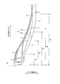
- FIG. 1 is a cross-sectional view in the tire meridian direction showing a pneumatic tire according to an embodiment of the present invention.
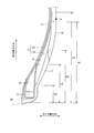
- FIG. 2 is an enlarged view showing a bead portion and a sidewall portion of the pneumatic tire shown in FIG.
- FIG. 3 is an enlarged view showing the bead portion described in FIG.
- FIG. 4 is an explanatory view showing a modified example of the pneumatic tire shown in FIG.
- FIG. 5 is a table showing results of performance tests of pneumatic tires according to the embodiment of the present invention.
- FIG. 1 is a cross-sectional view in the tire meridian direction showing a pneumatic tire according to an embodiment of the present invention.
- the figure shows a cross-sectional view of one side region in the tire radial direction.
- the figure shows a radial tire for passenger cars having an aspect ratio of 60% or more as an example of a pneumatic tire.
- the cross section in the tire meridian direction is defined as the cross section when the tire is cut along a plane including the tire rotation axis (not shown).
- the tire equatorial plane CL is defined as a plane that passes through the midpoint of the tire cross-section width measurement point defined by JATMA and is perpendicular to the tire rotation axis.
- the tire width direction is defined as a direction parallel to the tire rotation axis, and the tire radial direction is defined as a direction perpendicular to the tire rotation axis.
- the point T is the tire ground contact end, and the point A is the tire maximum width position.
- the pneumatic tire 1 has an annular structure centered on the tire rotation axis, and has a pair of bead cores 11 and 11, a pair of bead fillers 12 and 12, a carcass layer 13, a belt layer 14, and a tread rubber 15. , A pair of sidewall rubbers 16 and 16, a pair of rim cushion rubbers 17 and 17, and an inner liner 18 (see FIG. 1).
- the pair of bead cores 11 and 11 are formed by winding one or a plurality of bead wires made of steel in an annular shape and in multiple layers, and are embedded in the bead part to form the cores of the left and right bead parts.
- the pair of bead fillers 12, 12 are arranged on the outer circumferences of the pair of bead cores 11, 11 in the tire radial direction to reinforce the bead portion.
- the carcass layer 13 has a single-layer structure composed of one carcass ply or a multilayer structure formed by laminating a plurality of carcass plies.
- the carcass layer 13 is bridged in a toroidal shape between the left and right bead cores 11 to form a tire frame. Make up. Further, both ends of the carcass layer 13 are rolled back and locked to the outside in the tire width direction so as to surround the bead core 11 and the bead filler 12.
- the carcass ply of the carcass layer 13 is formed by coating a plurality of carcass cords made of steel or an organic fiber material (for example, aramid, nylon, polyester, rayon, etc.) with coated rubber and rolling the carcass cord.
- the cord angle is 100 [deg] or less (defined as an inclination angle in the longitudinal direction of the carcass cord with respect to the tire circumferential direction).
- the belt layer 14 is formed by laminating a plurality of belt plies 141 to 144, and is arranged around the outer circumference of the carcass layer 13.
- the belt plies 141 to 144 include a pair of cross belts 141 and 142, a belt cover 143, and a belt edge cover 144.
- the pair of cross belts 141 and 142 are formed by coating a plurality of belt cords made of steel or an organic fiber material with a coating rubber and rolling the cord cords, and have an absolute value of a cord angle of 25 [deg] or more and 33 [deg] or less.
- the pair of intersecting belts 141 and 142 have cord angles (defined as inclination angles in the longitudinal direction of the belt cord with respect to the tire circumferential direction) of mutually different signs, and the longitudinal directions of the belt cords intersect each other. Are stacked (so-called cross-ply structure).
- the pair of cross belts 141 and 142 are laminated and arranged on the outer side of the carcass layer 13 in the tire radial direction.
- the belt cover 143 and the belt edge cover 144 are configured by coating a belt cover cord made of steel or an organic fiber material with a coat rubber, and have an absolute value of a cord angle of 0 [deg] or more and 10 [deg] or less. Further, the belt cover 143 and the belt edge cover 144 are, for example, a strip material formed by coating one or more belt cover cords with coat rubber, and the strip material is applied to the outer peripheral surfaces of the cross belts 141 and 142. It is configured to be wound plural times in the tire circumferential direction and spirally.
- the tread rubber 15 is arranged on the tire radial outer periphery of the carcass layer 13 and the belt layer 14 to form a tread portion of the tire.
- the pair of sidewall rubbers 16 and 16 are arranged on the tire width direction outer side of the carcass layer 13 to form left and right sidewall portions.
- the pair of rim cushion rubbers 17, 17 extend from the tire radial direction inner side of the rewinding portions of the left and right bead cores 11, 11 and the carcass layer 13 to the tire width direction outer side, and form a rim fitting surface of the bead portion.
- the inner liner 18 is an air permeation preventive layer that is arranged on the inner surface of the tire and covers the carcass layer 13.
- the inner liner 18 suppresses oxidation due to the exposure of the carcass layer 13 and also prevents leakage of air filled in the tire.
- the inner liner 18 is made of, for example, a rubber composition containing butyl rubber as a main component, a thermoplastic resin, a thermoplastic elastomer composition obtained by blending an elastomer component in a thermoplastic resin, or the like. Further, in the configuration of FIG. 1, the radially inner end portion of the inner liner 18 is sandwiched between the carcass layer 13 and the rim cushion rubber 17 and extends to the radially inner side of the bead core 11 (see FIG. 3 described later). ).
- the tire total width SW and the tire cross-section height SH have a relationship of 1.25 ⁇ SW/SH ⁇ 1.80. Therefore, the tire flatness ratio is set to be relatively high.
- the tire total width SW is measured as a linear distance between the sidewalls (including all parts such as tire side patterns and letters) when the tire is mounted on a specified rim and a specified internal pressure is applied and the tire is in an unloaded state. To be done.
- the tire cross-section height SH is 1/2 the difference between the tire outer diameter and the rim diameter, and is measured with the tire mounted on the specified rim and applying the specified internal pressure, as well as in the unloaded state.
- “Regulated rim” means “applicable rim” specified by JATMA, “Design Rim” specified by TRA, or “Measuring Rim” specified by ETRTO.
- the specified internal pressure means the "maximum air pressure” specified by JATMA, the maximum value of "TIRE LOAD LIMITS AT VARIOUS COLD INFLATION PRESSURES” specified by TRA, or “INFLATION PRESSURES” specified by ETRTO.
- the specified load refers to the "maximum load capacity" specified in JATMA, the maximum value of "TIRE LOAD LIMITS AT VARIOUS COLD INFLATION PRESSURES" specified in TRA, or "LOAD CAPACITY” specified in ETRTO.
- the specified internal pressure is an air pressure of 180 [kPa] and the specified load is 88[%] of the maximum load capacity.
- the belt width Wb of the wide cross belt 141 preferably has a relationship of 1.10 ⁇ Wb/SH ⁇ 1.60 with respect to the tire cross-section height SH, and 1.20 ⁇ Wb/SH ⁇ 1. More preferably, it has a relationship of 40. Therefore, the belt width Wb is set relatively wide.
- the width of the belt ply is the distance between the left and right ends of each belt ply in the tire rotation axis direction.
- the tire is mounted on the specified rim, a specified internal pressure is applied, and the tire is measured under no load.
- the belt width Wb of the wide cross belt 141 preferably has a relationship of 0.75 ⁇ Wb/SW ⁇ 0.95 with respect to the tire total width SW, and 0.80 ⁇ Wb/SW ⁇ 0.90. It is more preferable to have the relationship of
- FIG. 2 is an enlarged view showing a bead portion and a sidewall portion of the pneumatic tire shown in FIG.
- FIG. 3 is an enlarged view showing the bead portion shown in FIG.
- the pneumatic tire 1 includes a pair of reinforcing rubbers 19, 19.
- the reinforcing rubber 19 has a rubber hardness equal to or higher than that of the bead filler 12, and has a rubber hardness higher than that of the sidewall rubber 16 and the rim cushion rubber 17.
- the rubber hardness Hs1 of the bead filler is preferably in the range of 70 ⁇ Hs1 ⁇ 98, and more preferably in the range of 75 ⁇ Hs1 ⁇ 85.
- the rubber hardness Hs2 of the reinforcing rubber 19 is in the range of 88 ⁇ Hs2 ⁇ 98.
- the difference between the rubber hardness Hs2 of the reinforcing rubber 19 and the rubber hardness Hs1 of the bead filler has a relationship of 1 ⁇ Hs2-Hs1.
- the upper limit of the difference Hs2-Hs1 is not particularly limited, but is limited by the range of the rubber hardness Hs1 and Hs2.
- the rubber hardness Hs3 of the rim cushion rubber is in the range of 65 ⁇ Hs3 ⁇ 75. Further, the difference between the rubber hardness Hs2 of the reinforcing rubber 19 and the rubber hardness Hs3 of the rim cushion rubber 17 has a relationship of 13 ⁇ Hs2-Hs3. The upper limit of the difference Hs2-Hs3 is not particularly limited, but is limited by the range of the rubber hardness Hs3, Hs2.
- Rubber hardness is measured according to JIS K6253.
- the reinforcing rubber 19 is arranged so as to be sandwiched between the rewinding portion 132 of the carcass layer 13 and the sidewall rubber 16 and the rim cushion rubber 17. Further, a pair of reinforcing rubbers 19, 19 are arranged on the left and right bead portions, respectively.
- the carcass layer 13 has a single-layer structure, and the end portion of the carcass layer 13 is rewound to the outside in the tire width direction so as to wrap the bead core 11 and the bead filler 12 as described above, and the rewound portion thereof. 132 contacts the main body 131 of the carcass layer 13 and is locked. Further, the reinforcing rubber 19 is arranged so as to cover the end of the rewinding portion 132 of the carcass layer 13 from the outside in the tire width direction. Further, the reinforcing rubber 19 is arranged so as to overlap the bead filler 12 in the tire radial direction, extends in the tire radial direction, and contacts the outer peripheral surface of the main body portion 131 of the carcass layer 13.
- the height H1 of the bead filler 12 has a relationship of 0.10 ⁇ H1/SH ⁇ 0.23 with respect to the tire cross-section height SH (see FIG. 1). Therefore, the height H1 of the bead filler 12 has a tire cross-section height ratio lower than the tire cross-section height ratio (0.25 to 0.35) of a general bead filler.
- the height H1 of the bead filler is the distance from the measurement point of the rim diameter to the radially outer end of the bead filler, and the tire is mounted on the specified rim to apply the specified internal pressure and is measured in the unloaded state.
- the tire cross-section height ratio H1/SH of the bead filler 12 is set to be lower than the general tire cross-section height ratio (0.25 to 0.35), so that the hardness of the riding comfort is eased.
- the riding comfort performance of the tire is improved, and the low-frequency road noise near 160 [Hz] is reduced, and the noise performance of the tire is improved.
- the height H2 of the reinforcing rubber 19 preferably has a relationship of 0.40 ⁇ H2/SH ⁇ 0.55 with respect to the tire cross-section height SH, and 0.43 ⁇ H2/SH ⁇ 0.49. It is more preferable to have a relationship.
- the height H2 of the reinforcing rubber is the distance from the measurement point of the rim diameter to the radially outer end of the reinforcing rubber, and the tire is mounted on the specified rim to apply the specified internal pressure and is measured in the unloaded state.
- the difference between the height H2 of the reinforcing rubber 19 and the height H1 of the bead filler 12 has a relationship of 0.17 ⁇ (H2-H1)/SH ⁇ 0.45 with respect to the tire cross-section height SH. Is preferable, and it is more preferable that the relation of 0.20 ⁇ (H2 ⁇ H1)/SH ⁇ 0.35 is satisfied.
- the difference between the height H2 of the reinforcing rubber 19 and the height H1 of the bead filler 12 is preferably in the range of 30 [mm] ⁇ H2-H1.
- the upper limit of the difference H2-H1 is not particularly limited, but is limited by the range of the heights H1 and H2 described above.
- the reinforcing rubber 19 is disposed between the rewinding portion 132 of the carcass layer 13 and the sidewall rubber 16 and the rim cushion rubber 17, the vibration damping property is improved and the riding comfort performance of the tire is improved. To do.
- the reinforcing rubber 19 reinforces the bead portion, and thus the deterioration of the double lane change performance of the tire due to the low bead filler 12 is suppressed. As a result, both the ride comfort performance of the tire and the double lane change performance are compatible, and the noise performance of the tire is improved.
- the overlap amount L1 of the reinforcing rubber 19 with respect to the bead filler 12 in the tire radial direction has a relationship of 0.15 ⁇ L1/L0 ⁇ 0.65 with respect to the radial length L0 of the bead filler 12. It is preferable to have, and it is more preferable to have a relationship of 0.30 ⁇ L1/L0 ⁇ 0.60. Therefore, the overlap amount L1 of the reinforcing rubber 19 is shorter than the radial length L0 of the bead filler 12, and the radially inner end portion of the reinforcing rubber 19 is on the tire radial direction outer side than the outer peripheral surface of the bead core 11. Further, the overlap amount L1 of the reinforcing rubber 19 is preferably in the range of 5.0 [mm] ⁇ L1. The upper limit of the overlap amount L1 is not particularly limited, but is limited by the condition of the ratio L1/L0 described above.
- the cross-sectional area S2 of the reinforcing rubber 19 in a cross-sectional view in the tire meridian direction preferably has a relationship of 1.10 ⁇ S2/S1 ⁇ 2.70 with respect to the cross-sectional area S1 of the bead filler 12, and 1.25 It is more preferable to have a relationship of ⁇ S2/S1 ⁇ 1.60.
- the ratio S2/S1 of the cross-sectional area S2 of the reinforcing rubber 19 is optimized. That is, the lower limit secures the cross-sectional area S1 of the reinforcing rubber 19, and the damping effect of vibration by the reinforcing rubber 19 and the reinforcing effect of the bead portion are secured.
- the upper limit suppresses deterioration of the riding comfort performance and noise performance of the tire due to the excessively large reinforcing rubber 19.
- the difference between the height H1 of the bead filler 12 and the rim flange height H0 of the specified rim 20 is preferably in the range of 0 [mm] ⁇ H1 ⁇ H0, and 5.0 [mm] More preferably, it is in the range of ⁇ H1 ⁇ H0. Therefore, the bead filler 12 extends beyond the maximum height position of the specified rim 20 and extends outward in the tire radial direction.
- the upper limit of the difference H1-H0 is not particularly limited, but is limited by other conditions related to the height H1.
- Rim flange height H0 is measured as the distance from the rim diameter measurement point to the radially outer end of the specified rim.
- the difference between the height H2 of the reinforcing rubber 19 and the height H3 of the rim cushion rubber 17 is 0.10 ⁇ (H2 ⁇ H3)/SH ⁇ 0.30 with respect to the tire cross-section height SH. It is preferable to have the relationship of 0.15 ⁇ (H2 ⁇ H3)/SH ⁇ 0.25. Therefore, the reinforcing rubber 19 extends beyond the maximum height position of the rim cushion rubber 17 and extends outward in the tire radial direction.
- the height H3 of the rim cushion rubber 17 has a relationship of 0.25 ⁇ H3/SH ⁇ 0.35 with respect to the tire cross-section height SH.
- the height H3 of the rim cushion rubber is the distance from the rim diameter measurement point to the radially outer end of the rim cushion rubber, and is measured in a non-loaded state with the tire mounted on the specified rim and applying the specified internal pressure.
- an imaginary line X passing through the end point P on the radially outer side of the bead filler 12 and perpendicular to the tire bore surface is defined.
- the thickness T2 of the reinforcing rubber 19 and the thickness T3 of the rim cushion rubber 17 on the imaginary line X have a relationship of 0.45 ⁇ T2/(T2+T3) ⁇ 0.70. It is more preferable to have a relationship of 50 ⁇ T2/(T2+T3) ⁇ 0.60.
- the thickness T2 of the reinforcing rubber 19 on the imaginary line X is preferably in the range of 3.0 [mm] ⁇ T2 ⁇ 5.0 [mm].
- the height H4 of the winding portion 132 of the carcass layer 13 has a relationship of 0.20 ⁇ H4/SH ⁇ 0.65 with respect to the tire cross-section height SH. As a result, the height H4 of the winding portion 132 of the carcass layer 13 is optimized.
- the height H4 of the winding portion of the carcass layer is the distance from the measurement point of the rim diameter to the radially outer end of the winding portion, and the tire is mounted on the specified rim to apply the specified internal pressure and is measured in the unloaded state. To be done.
- the difference between the height H4 of the rewinding portion 132 of the carcass layer 13 and the height H1 of the bead filler 12 is 0.10 ⁇ (H4-H1)/SH with respect to the tire cross-section height SH. It is preferable to have a relationship, and it is more preferable to have a relationship of 0.25 ⁇ (H4 ⁇ H1)/SH. As a result, the height H4 of the winding portion 132 of the carcass layer 13 is secured, and the tension of the carcass layer 13 is secured.
- the upper limit of the ratio (H4-H1)/SH is not particularly limited, but is limited by other conditions.
- FIG. 4 is an explanatory view showing a modified example of the pneumatic tire shown in FIG.
- the same components as those shown in FIG. 2 are designated by the same reference numerals, and the description thereof will be omitted.
- the carcass layer 13 has a so-called low turn-up structure, and the ratio H4/SH between the height H4 of the rewind portion 132 of the carcass layer 13 and the tire cross-section height SH is 0.20 ⁇ H4/SH ⁇ . It is in the range of 0.45. Further, the ratio H4/SH is preferably in the range of 0.25 ⁇ H4/SH ⁇ 0.35. Such a configuration is preferable in that the hardness of riding comfort is alleviated.
- the carcass layer 13 has a high turn-up structure, and the ratio H4/SH is in the range of 0.45 ⁇ H4/SH ⁇ 0.65. Further, the ratio H4/SH is preferably in the range of 0.50 ⁇ H4/SH ⁇ 0.60. Such a configuration is preferable in that the damping property of vibration is improved.
- the pneumatic tire 1 includes the pair of bead cores 11 and 11, the pair of bead fillers 12 and 12 arranged radially outside of the pair of bead cores 11 and 11, the bead core 11 and the bead filler 12.
- a carcass layer 13 that wraps around the tire and is rewound to the outside in the tire width direction, a pair of cross belts 141 and 142 arranged on the outside in the radial direction of the carcass layer 13, a tread rubber 15, a sidewall rubber 16, and a rim cushion rubber 17. (See FIG. 2).
- the pneumatic tire 1 has a rubber hardness higher than that of the rim cushion rubber 17, and a reinforcement disposed between the rewind portion 132 of the carcass layer 13 and the sidewall rubber 16 and the rim cushion rubber 17.
- the rubber 19 is provided (see FIG. 3).
- the height H1 of the bead filler 12 based on the measurement point of the rim diameter has a relationship of 0.10 ⁇ H1/SH ⁇ 0.23 with respect to the tire cross-section height SH.
- the height H2 of the reinforcing rubber 19 based on the measurement point of the rim diameter has a relationship of 0.40 ⁇ H2/SH ⁇ 0.55 with respect to the tire cross-section height SH.
- cross-sectional area S2 of the reinforcing rubber 19 in the cross-sectional view in the meridian direction of the tire has a relationship of 1.10 ⁇ S2/S1 ⁇ 2.70 with respect to the cross-sectional area S1 of the bead filler.
- the reinforcing rubber 19 reinforces the bead portion, so that the deterioration of the double lane change performance of the tire due to the low bead filler 12 is suppressed. Further, (3) since the ratio S2/S1 of the cross-sectional area S2 of the reinforcing rubber 19 is optimized, the damping effect of vibration by the reinforcing rubber 19 and the reinforcing effect of the bead portion are secured, and the reinforcing rubber 19 is excessively large. The deterioration of the riding comfort performance and noise performance of the tire due to As a result, the ride comfort performance of the tire and the double lane change performance are compatible with each other, and the noise performance of the tire is improved.
- the difference between the height H2 of the reinforcing rubber 19 and the height H1 of the bead filler 12 is 0.17 ⁇ (H2-H1)/SH ⁇ 0 with respect to the tire cross-section height SH. .45 relationship (see FIG. 2).
- the lower limit has an advantage of ensuring the vibration damping effect and the bead portion reinforcing function of the reinforcing rubber 19.
- the above upper limit has an advantage that deterioration of the riding comfort performance and noise performance of the tire due to the excessively large reinforcing rubber 19 is suppressed.
- the overlap amount L1 of the reinforcing rubber 19 with respect to the bead filler 12 in the tire radial direction is 0.15 ⁇ L1/L0 ⁇ 0.65 with respect to the radial length L0 of the bead filler 12. (See FIG. 3).
- the lower limit has an advantage of ensuring the vibration damping effect and the bead portion reinforcing function of the reinforcing rubber 19.
- the above upper limit has an advantage that deterioration of the riding comfort performance and noise performance of the tire due to the excessively large reinforcing rubber 19 is suppressed.
- the difference between the rubber hardness Hs2 of the reinforcing rubber 19 and the rubber hardness Hs1 of the bead filler 12 has a relationship of 1 ⁇ Hs2-Hs1.
- the reinforcing rubber 19 since the reinforcing rubber 19 has different rubber hardness with respect to the bead filler 12, there is an advantage that the damping action of vibration by the reinforcing rubber 19 can be easily adjusted.
- the rubber hardness Hs2 of the reinforcing rubber 19 is in the range of 88 ⁇ Hs2 ⁇ 98. Thereby, there is an advantage that the rubber hardness Hs2 of the reinforcing rubber 19 is secured.
- the difference between the height H1 of the bead filler 12 and the rim flange height H0 of the specified rim has a relationship of 0 [mm] ⁇ H1 ⁇ H0 (see FIG. 2). This has the advantage that the height H1 of the bead filler 12 is secured and the strength of the bead portion is secured.
- the difference between the height H2 of the reinforcing rubber 19 and the height H3 of the rim cushion rubber 17 is 0.10 ⁇ (H2-H3)/SH ⁇ with respect to the tire cross-section height SH. It has a relationship of 0.30 (see FIG. 2). This has the advantage that the height H2 of the reinforcing rubber 19 is optimized.
- the height H3 of the rim cushion rubber 17 based on the measurement point of the rim diameter has a relationship of 0.25 ⁇ H3/SH ⁇ 0.35 with respect to the tire cross-section height SH.
- This has the advantage that the height H3 of the rim cushion rubber 17 is optimized.
- an imaginary line X that passes through the radially outer end point P of the bead filler 12 and is perpendicular to the tire bore surface is defined, and the thickness T2 of the reinforcing rubber 19 and the rim cushion on the imaginary line X are defined.
- the thickness T3 of the rubber 17 has a relationship of 0.50 ⁇ T2/(T2+T3) ⁇ 0.67 (see FIG. 3).
- the difference between the rubber hardness Hs2 of the reinforcing rubber 19 and the rubber hardness Hs3 of the rim cushion rubber 17 has a relationship of 13 ⁇ Hs2-Hs3.
- the height H4 of the rewinding portion 132 of the carcass layer 13 has a relationship of 0.20 ⁇ H4/SH ⁇ 0.65 with respect to the tire cross-section height SH (see FIG. 2). .. Thereby, there is an advantage that the height H4 of the winding portion 132 of the carcass layer 13 is optimized.
- the difference between the height H4 of the rewinding portion 132 of the carcass layer 13 and the height H1 of the bead filler 12 based on the measurement point of the rim diameter is different from the tire cross-section height SH. It has a relationship of 0.10 ⁇ (H4 ⁇ H1)/SH (see FIG. 2). Thereby, there is an advantage that the height H4 of the winding portion 132 of the carcass layer 13 is secured and the tension of the carcass layer 13 is secured.
- the belt width Wb of the wide cross belt 141 has a relationship of 1.10 ⁇ Wb/SH ⁇ 1.60 with respect to the tire cross-section height SH (see FIG. 1).
- the above lower limit and upper limit have an advantage that the riding comfort performance and the noise performance of the tire are compatible with each other.
- the belt width Wb of the wide cross belt 141 has a relationship of 0.75 ⁇ Wb/SW ⁇ 0.95 with respect to the total tire width SW (see FIG. 1).
- the above lower limit and upper limit have an advantage that the riding comfort performance and the noise performance of the tire are compatible with each other.
- this pneumatic tire 1 is a radial tire for passenger cars having an aspect ratio of 60% or more.
- this configuration is applied to a passenger car tire having a high flatness, there is an advantage that the above-mentioned reinforcing rubber 19 can remarkably improve the riding comfort performance and the double lane change performance.
- FIG. 5 is a chart showing the results of the performance test of the pneumatic tire according to the embodiment of the present invention.
- test tires were evaluated for (1) riding comfort performance, (2) double lane change performance, and (3) noise performance.
- a test tire with a tire size of 235/65R17 is mounted on a rim with a rim size of 17 ⁇ 7J, and an internal pressure of 240 [kPa] and a specified load of JATMA are applied to the test tire. Further, the test tires are attached to all wheels of a front-wheel drive minivan vehicle having a displacement of 3.5 [L], which is a test vehicle.
- test vehicle coasts on a test course on a dry road surface and assumes continuous emergency lane change of the vehicle, and performs continuous lane changes to the left and right along a predetermined travel line. Then, the approach speed limit to the test course is measured and evaluated. This evaluation is performed by index evaluation using the conventional example as a reference (100), and the larger the value, the more preferable.
- the test tire of the example has the configuration of FIGS. 1 and 2, and has the bead filler 12 having a low height H1 and the reinforcing rubber 19. Further, the tire cross-section height SH is 150 [mm], the rubber hardness Hs1 of the bead filler 12 is 90, the rubber hardness Hs2 of the reinforcing rubber 19 is 95, and the rubber hardness Hs3 of the rim cushion rubber is 70, and the rubber hardness of the sidewall rubber 16 is 53.
- the ratio S2/S1 between the cross-sectional area S2 of the reinforcing rubber 19 and the cross-sectional area S1 of the bead filler in the test tire of Example 1 is set to be very large.
- test tires of the examples improve the riding comfort performance, double lane change performance, and noise performance of the tires.
Landscapes
- Engineering & Computer Science (AREA)
- Mechanical Engineering (AREA)
- Tires In General (AREA)
Abstract
この空気入りタイヤ1は、リムクッションゴム17のゴム硬さよりも高いゴム硬さを有すると共に、カーカス層13の巻き返し部132とサイドウォールゴム16およびリムクッションゴム17との間に配置された補強ゴム19を備える。また、リム径の測定点を基準としたビードフィラー12の高さH1が、タイヤ断面高さSHに対して0.10≦H1/SH≦0.23の関係を有する。また、リム径の測定点を基準とした補強ゴム19の高さH2が、タイヤ断面高さSHに対して0.40≦H2/SH≦0.55の関係を有する。また、タイヤ子午線方向の断面視における補強ゴム19の断面積S2が、ビードフィラーの断面積S1に対して1.10≦S2/S1≦2.70の関係を有する。
Description
この発明は、空気入りタイヤに関し、さらに詳しくは、タイヤの乗心地性能とダブルレーンチェンジ性能とを両立できる空気入りタイヤに関する。
ミニバンなどに装着される近年の空気入りタイヤでは、タイヤの乗心地性能を向上するために、一般的なタイヤ断面高さ比(0.25~0.35)よりも低いタイヤ断面高さ比をもつビードフィラーが採用されている。かかる低いビードフィラーを備える従来の空気入りタイヤとして、特許文献1に記載される技術が知られている。
しかしながら、上記のような低いビードフィラーを備える構成では、相対的にタイヤ断面高さが高くなり、タイヤのダブルレーンチェンジ性能が低下するという課題がある。
そこで、この発明は、上記に鑑みてなされたものであって、タイヤの乗心地性能とダブルレーンチェンジ性能とを両立できる空気入りタイヤを提供することを目的とする。
上記目的を達成するため、この発明にかかる空気入りタイヤは、一対のビードコアと、前記一対のビードコアの径方向外側に配置される一対のビードフィラーと、前記ビードコアおよび前記ビードフィラーを包み込みタイヤ幅方向外側に巻き返されたカーカス層と、前記カーカス層の径方向外側に配置された一対の交差ベルトと、トレッドゴム、サイドウォールゴムおよびリムクッションゴムとを備える空気入りタイヤであって、前記リムクッションゴムのゴム硬さよりも高いゴム硬さを有すると共に、前記カーカス層の巻き返し部と前記サイドウォールゴムおよび前記リムクッションゴムとの間に配置された補強ゴムを備え、リム径の測定点を基準とした前記ビードフィラーの高さH1が、タイヤ断面高さSHに対して0.10≦H1/SH≦0.23の関係を有し、リム径の測定点を基準とした前記補強ゴムの高さH2が、タイヤ断面高さSHに対して0.40≦H2/SH≦0.55の関係を有し、且つ、タイヤ子午線方向の断面視における前記補強ゴムの断面積S2が、前記ビードフィラーの断面積S1に対して1.10≦S2/S1≦2.70の関係を有することを特徴とする。
この発明にかかる空気入りタイヤによれば、(1)ビードフィラーのタイヤ断面高さ比H1/SHが一般的なタイヤ断面高さ比(0.25~0.35)よりも低く設定されるので、乗り心地の硬さが緩和されてタイヤの乗心地性能が向上する。また、(2)補強ゴムがカーカス層の巻き返し部とサイドウォールゴムおよびリムクッションゴムとの間に配置されるので、振動の減衰性が向上してタイヤの乗心地性能が向上する。同時に、補強ゴムがビード部を補強することにより、上記した低いビードフィラーに起因するタイヤのダブルレーンチェンジ性能の低下が抑制される。さらに、(3)補強ゴムの断面積比S2/S1が適正化されるので、補強ゴムによる振動の減衰性作用およびビード部の補強作用が確保され、また、補強ゴムが過大となることに起因するタイヤの乗心地性能の悪化が抑制される。これらにより、タイヤの乗心地性能およびダブルレーンチェンジ性能が両立する利点がある。
以下、この発明につき図面を参照しつつ詳細に説明する。なお、この実施の形態によりこの発明が限定されるものではない。また、この実施の形態の構成要素には、発明の同一性を維持しつつ置換可能かつ置換自明なものが含まれる。また、この実施の形態に記載された複数の変形例は、当業者自明の範囲内にて任意に組み合わせが可能である。
[空気入りタイヤ]
図1は、この発明の実施の形態にかかる空気入りタイヤを示すタイヤ子午線方向の断面図である。同図は、タイヤ径方向の片側領域の断面図を示している。また、同図は、空気入りタイヤの一例として、偏平率60[%]以上の乗用車用ラジアルタイヤを示している。
図1は、この発明の実施の形態にかかる空気入りタイヤを示すタイヤ子午線方向の断面図である。同図は、タイヤ径方向の片側領域の断面図を示している。また、同図は、空気入りタイヤの一例として、偏平率60[%]以上の乗用車用ラジアルタイヤを示している。
同図において、タイヤ子午線方向の断面は、タイヤ回転軸(図示省略)を含む平面でタイヤを切断したときの断面として定義される。また、タイヤ赤道面CLは、JATMAに規定されたタイヤ断面幅の測定点の中点を通りタイヤ回転軸に垂直な平面として定義される。また、タイヤ幅方向は、タイヤ回転軸に平行な方向として定義され、タイヤ径方向は、タイヤ回転軸に垂直な方向として定義される。また、点Tは、タイヤ接地端であり、点Aは、タイヤ最大幅位置である。
空気入りタイヤ1は、タイヤ回転軸を中心とする環状構造を有し、一対のビードコア11、11と、一対のビードフィラー12、12と、カーカス層13と、ベルト層14と、トレッドゴム15と、一対のサイドウォールゴム16、16と、一対のリムクッションゴム17、17と、インナーライナ18とを備える(図1参照)。
一対のビードコア11、11は、スチールから成る1本あるいは複数本のビードワイヤを環状かつ多重に巻き廻して成り、ビード部に埋設されて左右のビード部のコアを構成する。一対のビードフィラー12、12は、一対のビードコア11、11のタイヤ径方向外周にそれぞれ配置されてビード部を補強する。
カーカス層13は、1枚のカーカスプライから成る単層構造あるいは複数枚のカーカスプライを積層して成る多層構造を有し、左右のビードコア11、11間にトロイダル状に架け渡されてタイヤの骨格を構成する。また、カーカス層13の両端部は、ビードコア11およびビードフィラー12を包み込むようにタイヤ幅方向外側に巻き返されて係止される。また、カーカス層13のカーカスプライは、スチールあるいは有機繊維材(例えば、アラミド、ナイロン、ポリエステル、レーヨンなど)から成る複数のカーカスコードをコートゴムで被覆して圧延加工して構成され、80[deg]以上100[deg]以下のコード角度(タイヤ周方向に対するカーカスコードの長手方向の傾斜角として定義される。)を有する。
ベルト層14は、複数のベルトプライ141~144を積層して成り、カーカス層13の外周に掛け廻されて配置される。ベルトプライ141~144は、一対の交差ベルト141、142と、ベルトカバー143およびベルトエッジカバー144とを含む。
一対の交差ベルト141、142は、スチールあるいは有機繊維材から成る複数のベルトコードをコートゴムで被覆して圧延加工して構成され、絶対値で25[deg]以上33[deg]以下のコード角度を有する。また、一対の交差ベルト141、142は、相互に異符号のコード角度(タイヤ周方向に対するベルトコードの長手方向の傾斜角として定義される)を有し、ベルトコードの長手方向を相互に交差させて積層される(いわゆるクロスプライ構造)。また、一対の交差ベルト141、142は、カーカス層13のタイヤ径方向外側に積層されて配置される。
ベルトカバー143およびベルトエッジカバー144は、スチールあるいは有機繊維材から成るベルトカバーコードをコートゴムで被覆して構成され、絶対値で0[deg]以上10[deg]以下のコード角度を有する。また、ベルトカバー143およびベルトエッジカバー144は、例えば、1本あるいは複数本のベルトカバーコードをコートゴムで被覆して成るストリップ材であり、このストリップ材を交差ベルト141、142の外周面に対してタイヤ周方向に複数回かつ螺旋状に巻き付けて構成される。
トレッドゴム15は、カーカス層13およびベルト層14のタイヤ径方向外周に配置されてタイヤのトレッド部を構成する。一対のサイドウォールゴム16、16は、カーカス層13のタイヤ幅方向外側にそれぞれ配置されて左右のサイドウォール部を構成する。一対のリムクッションゴム17、17は、左右のビードコア11、11およびカーカス層13の巻き返し部のタイヤ径方向内側からタイヤ幅方向外側に延在して、ビード部のリム嵌合面を構成する。
インナーライナ18は、タイヤ内腔面に配置されてカーカス層13を覆う空気透過防止層であり、カーカス層13の露出による酸化を抑制し、また、タイヤに充填された空気の洩れを防止する。また、インナーライナ18は、例えば、ブチルゴムを主成分とするゴム組成物、熱可塑性樹脂、熱可塑性樹脂中にエラストマー成分をブレンドした熱可塑性エラストマー組成物などから構成される。また、図1の構成では、インナーライナ18の径方向内側端部が、カーカス層13およびリムクッションゴム17に挟み込まれて、ビードコア11の径方向内側まで延在している(後述する図3参照)。
また、図1において、タイヤ総幅SWとタイヤ断面高さSHとが、1.25≦SW/SH≦1.80の関係を有する。したがって、タイヤ偏平率が比較的高めに設定される。
タイヤ総幅SWは、タイヤを規定リムに装着して規定内圧を付与すると共に無負荷状態としたときのサイドウォール間の(タイヤ側面の模様、文字などのすべての部分を含む)直線距離として測定される。
タイヤ断面高さSHは、タイヤ外径とリム径との差の1/2の距離であり、タイヤを規定リムに装着して規定内圧を付与すると共に無負荷状態として測定される。
規定リムとは、JATMAに規定される「適用リム」、TRAに規定される「Design Rim」、あるいはETRTOに規定される「Measuring Rim」をいう。また、規定内圧とは、JATMAに規定される「最高空気圧」、TRAに規定される「TIRE LOAD LIMITS AT VARIOUS COLD INFLATION PRESSURES」の最大値、あるいはETRTOに規定される「INFLATION PRESSURES」をいう。また、規定荷重とは、JATMAに規定される「最大負荷能力」、TRAに規定される「TIRE LOAD LIMITS AT VARIOUS COLD INFLATION PRESSURES」の最大値、あるいはETRTOに規定される「LOAD CAPACITY」をいう。ただし、JATMAにおいて、乗用車用タイヤの場合には、規定内圧が空気圧180[kPa]であり、規定荷重が最大負荷能力の88[%]である。
また、幅広な交差ベルト141のベルト幅Wbが、タイヤ断面高さSHに対して1.10≦Wb/SH≦1.60の関係を有することが好ましく、1.20≦Wb/SH≦1.40の関係を有することがより好ましい。したがって、ベルト幅Wbが比較的広めに設定される。
ベルトプライの幅は、各ベルトプライの左右の端部のタイヤ回転軸方向の距離であり、タイヤを規定リムに装着して規定内圧を付与すると共に無負荷状態として測定される。
また、幅広な交差ベルト141のベルト幅Wbが、タイヤ総幅SWに対して0.75≦Wb/SW≦0.95の関係を有することが好ましく、0.80≦Wb/SW≦0.90の関係を有することがより好ましい。
[ビード部の補強構造]
図2は、図1に記載した空気入りタイヤのビード部およびサイドウォール部を示す拡大図である。図3は、図2に記載したビード部を示す拡大図である。
図2は、図1に記載した空気入りタイヤのビード部およびサイドウォール部を示す拡大図である。図3は、図2に記載したビード部を示す拡大図である。
図1に示すように、空気入りタイヤ1は、一対の補強ゴム19、19を備える。補強ゴム19は、ビードフィラー12に対して同等以上のゴム硬さを有し、また、サイドウォールゴム16およびリムクッションゴム17よりも高いゴム硬さを有する。
具体的に、ビードフィラーのゴム硬さHs1が、70≦Hs1≦98の範囲にあることが好ましく、75≦Hs1≦85の範囲にあることがより好ましい。これに対して、補強ゴム19のゴム硬さHs2が、88≦Hs2≦98の範囲にある。また、補強ゴム19のゴム硬さHs2と前記ビードフィラーのゴム硬さHs1との差が、1≦Hs2-Hs1の関係を有することが好ましい。差Hs2-Hs1の上限は特に限定がないが、上記ゴム硬さHs1、Hs2の範囲により制約を受ける。
また、リムクッションゴムのゴム硬さHs3が、65≦Hs3≦75の範囲にある。また、補強ゴム19のゴム硬さHs2とリムクッションゴム17のゴム硬さHs3との差が、13≦Hs2-Hs3の関係を有する。差Hs2-Hs3の上限は特に限定がないが、上記ゴム硬さHs3、Hs2の範囲により制約を受ける。
ゴム硬さは、JIS K6253に準拠して測定される。
また、補強ゴム19は、カーカス層13の巻き返し部132とサイドウォールゴム16およびリムクッションゴム17との間に挟み込まれて配置される。また、一対の補強ゴム19、19が、左右のビード部にそれぞれ配置される。
図2の構成では、カーカス層13が単層構造を有し、上記のようにカーカス層13の端部がビードコア11およびビードフィラー12を包み込むようにタイヤ幅方向外側に巻き返され、その巻き返し部132がカーカス層13の本体部131に接触して係止されている。また、補強ゴム19が、カーカス層13の巻き返し部132の端部をタイヤ幅方向外側から覆って配置されている。また、補強ゴム19が、ビードフィラー12に対してタイヤ径方向にオーバーラップして配置され、また、タイヤ径方向に延在してカーカス層13の本体部131の外周面に接触している。
また、図2において、ビードフィラー12の高さH1が、タイヤ断面高さSH(図1参照)に対して0.10≦H1/SH≦0.23の関係を有する。したがって、ビードフィラー12の高さH1が、一般的なビードフィラーのタイヤ断面高さ比(0.25~0.35)よりも低いタイヤ断面高さ比を有する。
ビードフィラーの高さH1は、リム径の測定点からビードフィラーの径方向外側端部までの距離であり、タイヤを規定リムに装着して規定内圧を付与すると共に無負荷状態として測定される。
上記の構成では、ビードフィラー12のタイヤ断面高さ比H1/SHが一般的なタイヤ断面高さ比(0.25~0.35)よりも低く設定されるので、乗り心地の硬さが緩和されてタイヤの乗心地性能が向上し、また、160[Hz]付近の低周波ロードノイズが低減されてタイヤの騒音性能が向上する。
また、補強ゴム19の高さH2が、タイヤ断面高さSHに対して0.40≦H2/SH≦0.55の関係を有することが好ましく、0.43≦H2/SH≦0.49の関係を有することがより好ましい。
補強ゴムの高さH2は、リム径の測定点から補強ゴムの径方向外側端部までの距離であり、タイヤを規定リムに装着して規定内圧を付与すると共に無負荷状態として測定される。
また、補強ゴム19の高さH2とビードフィラー12の高さH1との差が、タイヤ断面高さSHに対して0.17≦(H2-H1)/SH≦0.45の関係を有することが好ましく、0.20≦(H2-H1)/SH≦0.35の関係を有することがより好ましい。また、補強ゴム19の高さH2とビードフィラー12の高さH1との差が、30[mm]≦H2-H1の範囲にあることが好ましい。差H2-H1の上限は、特に限定がないが、上記した高さH1、H2の範囲により制約を受ける。
上記の構成では、補強ゴム19がカーカス層13の巻き返し部132とサイドウォールゴム16およびリムクッションゴム17との間に配置されるので、振動の減衰性が向上してタイヤの乗心地性能が向上する。また、上記のような低いビードフィラーを備える構成では、相対的にタイヤ断面高さが高くなり、タイヤのダブルレーンチェンジ性能が低下するという課題がある。この点において、上記の構成では、補強ゴム19がビード部を補強することにより、上記した低いビードフィラー12に起因するタイヤのダブルレーンチェンジ性能の低下が抑制される。これにより、タイヤの乗心地性能およびダブルレーンチェンジ性能が両立し、また、タイヤの騒音性能が向上する。
また、図3において、タイヤ径方向におけるビードフィラー12に対する補強ゴム19のオーバーラップ量L1が、ビードフィラー12の径方向長さL0に対して0.15≦L1/L0≦0.65の関係を有することが好ましく、0.30≦L1/L0≦0.60の関係を有することがより好ましい。したがって、補強ゴム19のオーバーラップ量L1がビードフィラー12の径方向長さL0よりも短く、補強ゴム19の径方向内側端部が、ビードコア11の外周面よりもタイヤ径方向外側にある。また、補強ゴム19のオーバーラップ量L1が5.0[mm]≦L1の範囲にあることが好ましい。オーバーラップ量L1の上限は、特に限定がないが、上記した比L1/L0の条件により制約を受ける。
また、タイヤ子午線方向の断面視における補強ゴム19の断面積S2が、ビードフィラー12の断面積S1に対して1.10≦S2/S1≦2.70の関係を有することが好ましく、1.25≦S2/S1≦1.60の関係を有することがより好ましい。これにより、補強ゴム19の断面積S2の比S2/S1が適正化される。すなわち、上記下限により、補強ゴム19の断面積S1が確保されて、補強ゴム19による振動の減衰性作用およびビード部の補強作用が確保される。また、上記上限により、補強ゴム19が過大となることに起因するタイヤの乗心地性能および騒音性能の悪化が抑制される。
また、図2において、ビードフィラー12の高さH1と規定リム20のリムフランジ高さH0との差が、0[mm]≦H1-H0の範囲にあることが好ましく、5.0[mm]≦H1-H0の範囲にあることがより好ましい。したがって、ビードフィラー12が規定リム20の最大高さ位置を越えてタイヤ径方向外側に延在する。差H1-H0の上限は、特に限定がないが、高さH1にかかる他の条件により制約を受ける。
リムフランジ高さH0は、リム径の測定点から規定リムの径方向外側端部までの距離として測定される。
また、図2において、補強ゴム19の高さH2とリムクッションゴム17の高さH3との差が、タイヤ断面高さSHに対して0.10≦(H2-H3)/SH≦0.30の関係を有することが好ましく、0.15≦(H2-H3)/SH≦0.25の関係を有することがより好ましい。したがって、補強ゴム19がリムクッションゴム17の最大高さ位置を越えてタイヤ径方向外側に延在する。
また、リムクッションゴム17の高さH3が、タイヤ断面高さSHに対して0.25≦H3/SH≦0.35の関係を有する。
リムクッションゴムの高さH3は、リム径の測定点からリムクッションゴムの径方向外側端部までの距離であり、タイヤを規定リムに装着して規定内圧を付与すると共に無負荷状態として測定される。
また、図3において、ビードフィラー12の径方向外側の端点Pを通りタイヤ内腔面に垂直な仮想線Xを定義する。このとき、仮想線X上における補強ゴム19の厚さT2とリムクッションゴム17の厚さT3とが、0.45≦T2/(T2+T3)≦0.70の関係を有することが好ましく、0.50≦T2/(T2+T3)≦0.60の関係を有することがより好ましい。また、仮想線X上における補強ゴム19の厚さT2が、3.0[mm]≦T2≦5.0[mm]の範囲にあることが好ましい。
また、図2において、カーカス層13の巻き返し部132の高さH4が、タイヤ断面高さSHに対して0.20≦H4/SH≦0.65の関係を有する。これにより、カーカス層13の巻き返し部132の高さH4が適正化される。
カーカス層の巻き返し部の高さH4は、リム径の測定点から巻き返し部の径方向外側端部までの距離であり、タイヤを規定リムに装着して規定内圧を付与すると共に無負荷状態として測定される。
また、図2において、カーカス層13の巻き返し部132の高さH4とビードフィラー12の高さH1との差が、タイヤ断面高さSHに対して0.10≦(H4-H1)/SHの関係を有することが好ましく、0.25≦(H4-H1)/SHの関係を有することがより好ましい。これにより、カーカス層13の巻き返し部132の高さH4が確保されて、カーカス層13の張力が確保される。比(H4-H1)/SHの上限は、特に限定がないが、他の条件により制約を受ける。
[変形例]
図4は、図2に記載した空気入りタイヤの変形例を示す説明図である。同図において、図2に記載した構成要素と同一のものについては、同一の符号を付し、その説明を省略する。
図4は、図2に記載した空気入りタイヤの変形例を示す説明図である。同図において、図2に記載した構成要素と同一のものについては、同一の符号を付し、その説明を省略する。
図2の構成では、カーカス層13がいわゆるローターンナップ構造を有し、カーカス層13の巻き返し部132の高さH4とタイヤ断面高さSHとの比H4/SHが0.20≦H4/SH≦0.45の範囲にある。また、比H4/SHが0.25≦H4/SH≦0.35の範囲にあることが好ましい。かかる構成では、乗り心地の硬さが緩和される点で好ましい。
これに対して、図4の構成では、カーカス層13がハイターンナップ構造を有し、比H4/SHが0.45≦H4/SH≦0.65の範囲にある。また、また、比H4/SHが0.50≦H4/SH≦0.60の範囲にあることが好ましい。かかる構成では、振動の減衰性が向上する点で好ましい。
[効果]
以上説明したように、この空気入りタイヤ1は、一対のビードコア11、11と、一対のビードコア11、11の径方向外側に配置される一対のビードフィラー12、12と、ビードコア11およびビードフィラー12を包み込みタイヤ幅方向外側に巻き返されたカーカス層13と、カーカス層13の径方向外側に配置された一対の交差ベルト141、142と、トレッドゴム15、サイドウォールゴム16およびリムクッションゴム17とを備える(図2参照)。また、空気入りタイヤ1は、リムクッションゴム17のゴム硬さよりも高いゴム硬さを有すると共に、カーカス層13の巻き返し部132とサイドウォールゴム16およびリムクッションゴム17との間に配置された補強ゴム19を備える(図3参照)。また、リム径の測定点を基準としたビードフィラー12の高さH1が、タイヤ断面高さSHに対して0.10≦H1/SH≦0.23の関係を有する。また、リム径の測定点を基準とした補強ゴム19の高さH2が、タイヤ断面高さSHに対して0.40≦H2/SH≦0.55の関係を有する。また、タイヤ子午線方向の断面視における補強ゴム19の断面積S2が、ビードフィラーの断面積S1に対して1.10≦S2/S1≦2.70の関係を有する。
以上説明したように、この空気入りタイヤ1は、一対のビードコア11、11と、一対のビードコア11、11の径方向外側に配置される一対のビードフィラー12、12と、ビードコア11およびビードフィラー12を包み込みタイヤ幅方向外側に巻き返されたカーカス層13と、カーカス層13の径方向外側に配置された一対の交差ベルト141、142と、トレッドゴム15、サイドウォールゴム16およびリムクッションゴム17とを備える(図2参照)。また、空気入りタイヤ1は、リムクッションゴム17のゴム硬さよりも高いゴム硬さを有すると共に、カーカス層13の巻き返し部132とサイドウォールゴム16およびリムクッションゴム17との間に配置された補強ゴム19を備える(図3参照)。また、リム径の測定点を基準としたビードフィラー12の高さH1が、タイヤ断面高さSHに対して0.10≦H1/SH≦0.23の関係を有する。また、リム径の測定点を基準とした補強ゴム19の高さH2が、タイヤ断面高さSHに対して0.40≦H2/SH≦0.55の関係を有する。また、タイヤ子午線方向の断面視における補強ゴム19の断面積S2が、ビードフィラーの断面積S1に対して1.10≦S2/S1≦2.70の関係を有する。
かかる構成では、(1)ビードフィラー12のタイヤ断面高さ比H1/SHが一般的なタイヤ断面高さ比(0.25~0.35)よりも低く設定されるので、乗り心地の硬さが緩和されてタイヤの乗心地性能が向上し、また、160[Hz]付近の低周波ロードノイズが低減されてタイヤの騒音性能が向上する。また、(2)補強ゴム19がカーカス層13の巻き返し部132とサイドウォールゴム16およびリムクッションゴム17との間に配置されるので、振動の減衰性が向上してタイヤの乗心地性能が向上する。同時に、補強ゴム19がビード部を補強することにより、上記した低いビードフィラー12に起因するタイヤのダブルレーンチェンジ性能の低下が抑制される。さらに、(3)補強ゴム19の断面積S2の比S2/S1が適正化されるので、補強ゴム19による振動の減衰性作用およびビード部の補強作用が確保され、また、補強ゴム19が過大となることに起因するタイヤの乗心地性能および騒音性能の悪化が抑制される。これらにより、タイヤの乗心地性能およびダブルレーンチェンジ性能が両立し、また、タイヤの騒音性能が向上する利点がある。
また、この空気入りタイヤ1では、補強ゴム19の高さH2とビードフィラー12の高さH1との差が、タイヤ断面高さSHに対して0.17≦(H2-H1)/SH≦0.45の関係を有する(図2参照)。上記下限により、補強ゴム19による振動の減衰性作用およびビード部の補強作用が確保される利点がある。上記上限により、補強ゴム19が過大となることに起因するタイヤの乗心地性能および騒音性能の悪化が抑制される利点がある。
また、この空気入りタイヤ1では、タイヤ径方向におけるビードフィラー12に対する補強ゴム19のオーバーラップ量L1が、ビードフィラー12の径方向長さL0に対して0.15≦L1/L0≦0.65の関係を有する(図3参照)。上記下限により、補強ゴム19による振動の減衰性作用およびビード部の補強作用が確保される利点がある。上記上限により、補強ゴム19が過大となることに起因するタイヤの乗心地性能および騒音性能の悪化が抑制される利点がある。
また、この空気入りタイヤ1では、補強ゴム19のゴム硬さHs2とビードフィラー12のゴム硬さHs1との差が、1≦Hs2-Hs1の関係を有する。かかる構成では、補強ゴム19がビードフィラー12に対して異なるゴム硬さを有することにより、補強ゴム19による振動の減衰性作用の調整が容易となる利点がある。
また、この空気入りタイヤでは、補強ゴム19のゴム硬さHs2が、88≦Hs2≦98の範囲にある。これにより、補強ゴム19のゴム硬さHs2が確保される利点がある。
また、この空気入りタイヤ1では、ビードフィラー12の高さH1と規定リムのリムフランジ高さH0との差が、0[mm]≦H1-H0の関係を有する(図2参照)。これにより、ビードフィラー12の高さH1が確保されて、ビード部の強度が確保される利点がある。
また、この空気入りタイヤ1では、補強ゴム19の高さH2とリムクッションゴム17の高さH3との差が、タイヤ断面高さSHに対して0.10≦(H2-H3)/SH≦0.30の関係を有する(図2参照)。これにより、補強ゴム19の高さH2が適正化される利点がある。
また、この空気入りタイヤ1では、リム径の測定点を基準としたリムクッションゴム17の高さH3が、タイヤ断面高さSHに対して0.25≦H3/SH≦0.35の関係を有する(図2参照)。これにより、リムクッションゴム17の高さH3が適正化される利点がある。
また、この空気入りタイヤ1では、ビードフィラー12の径方向外側の端点Pを通りタイヤ内腔面に垂直な仮想線Xを定義し、仮想線X上における補強ゴム19の厚さT2とリムクッションゴム17の厚さT3とが、0.50≦T2/(T2+T3)≦0.67の関係を有する(図3参照)。これにより、補強ゴム19の厚さT2がリムクッションゴム17の厚さT3に対して適正化される利点がある。
また、この空気入りタイヤ1では、補強ゴム19のゴム硬さHs2とリムクッションゴム17のゴム硬さHs3との差が、13≦Hs2-Hs3の関係を有する。これにより、補強ゴム19のゴム硬さHs2が適正化される利点がある。
また、この空気入りタイヤ1では、カーカス層13の巻き返し部132の高さH4が、タイヤ断面高さSHに対して0.20≦H4/SH≦0.65の関係を有する(図2参照)。これにより、カーカス層13の巻き返し部132の高さH4が適正化される利点がある。
また、この空気入りタイヤ1では、リム径の測定点を基準としたカーカス層13の巻き返し部132の高さH4とビードフィラー12の高さH1との差が、タイヤ断面高さSHに対して0.10≦(H4-H1)/SHの関係を有する(図2参照)。これにより、カーカス層13の巻き返し部132の高さH4が確保されて、カーカス層13の張力が確保される利点がある。
また、この空気入りタイヤ1では、幅広な交差ベルト141のベルト幅Wbが、タイヤ断面高さSHに対して1.10≦Wb/SH≦1.60の関係を有する(図1参照)。上記下限および上限により、タイヤの乗心地性能および騒音性能が両立する利点がある。
また、この空気入りタイヤ1では、幅広な交差ベルト141のベルト幅Wbが、タイヤ総幅SWに対して0.75≦Wb/SW≦0.95の関係を有する(図1参照)。上記下限および上限により、タイヤの乗心地性能および騒音性能が両立する利点がある。
また、この空気入りタイヤ1は、偏平率60[%]以上の乗用車用ラジアルタイヤである。上記の構成が高い偏平率の乗用車用タイヤに適用されることにより、上記した補強ゴム19による乗心地性能およびダブルレーンチェンジ性能の向上効果が顕著に得られる利点がある。
図5は、この発明の実施の形態にかかる空気入りタイヤの性能試験の結果を示す図表である。
この性能試験では、複数種類の試験タイヤについて、(1)乗心地性能、(2)ダブルレーンチェンジ性能および(3)騒音性能に関する評価が行われた。また、タイヤサイズ235/65R17の試験タイヤがリムサイズ17×7Jのリムに組み付けられ、この試験タイヤに240[kPa]の内圧およびJATMAの規定荷重が付与される。また、試験タイヤが、試験車両である排気量3.5[L]の前輪駆動のミニバン車の総輪に装着される。
(1)乗心地性能に関する評価では、試験車両がドライ路面のテストコースを走行して、専門のテストドライバーが乗り心地の硬さと振動の減衰性についてフィーリング評価を行う。この評価は、従来例を基準(100)とした指数評価により行われ、その数値が大きいほど好ましい。
(2)ダブルレーンチェンジ性能に関する評価では、試験車両がドライ路面のテストコースを惰性走行し、車両の緊急回避走行を想定して、所定の走行ラインに沿って左右に連続したレーンチェンジを行う。そして、テストコースへの進入限界速度が計測されて評価が行われる。この評価は、従来例を基準(100)とした指数評価により行われ、その数値が大きいほど好ましい。
(3)騒音性能に関する評価では、試験車両が粗い路面を有するテストコースを10[km/h]~20[km/h]で惰性走行し、テストドライバーが車内騒音(ロードノイズ)に関する官能評価を行う。この評価は、従来例を基準(100)とした指数評価により行われ、その数値が大きいほど好ましい。
実施例の試験タイヤは、図1および図2の構成を備え、低い高さH1を有するビードフィラー12と、補強ゴム19とを有する。また、タイヤ断面高さSHが150[mm]であり、ビードフィラー12のゴム硬さHs1が90であり、補強ゴム19のゴム硬さHs2が95であり、リムクッションゴムのゴム硬さHs3が70であり、サイドウォールゴム16のゴム硬さが53である。
従来例の試験タイヤは、実施例1の試験タイヤにおいて、補強ゴム19の断面積S2とビードフィラーの断面積S1との比S2/S1が非常に大きく設定されている。
試験結果に示すように、実施例の試験タイヤでは、タイヤの乗心地性能、ダブルレーンチェンジ性能および騒音性能が向上することが分かる。
1 空気入りタイヤ;11 ビードコア;12 ビードフィラー;13 カーカス層;131 本体部;132 巻き返し部;14 ベルト層;141、142 交差ベルト;143 ベルトカバー;144 ベルトエッジカバー;15 トレッドゴム;16 サイドウォールゴム;17 リムクッションゴム;18 インナーライナ;19 補強ゴム;20 規定リム
Claims (15)
- 一対のビードコアと、前記一対のビードコアの径方向外側に配置される一対のビードフィラーと、前記ビードコアおよび前記ビードフィラーを包み込みタイヤ幅方向外側に巻き返されたカーカス層と、前記カーカス層の径方向外側に配置された一対の交差ベルトと、トレッドゴム、サイドウォールゴムおよびリムクッションゴムとを備える空気入りタイヤであって、
前記リムクッションゴムのゴム硬さよりも高いゴム硬さを有すると共に、前記カーカス層の巻き返し部と前記サイドウォールゴムおよび前記リムクッションゴムとの間に配置された補強ゴムを備え、
リム径の測定点を基準とした前記ビードフィラーの高さH1が、タイヤ断面高さSHに対して0.10≦H1/SH≦0.23の関係を有し、
リム径の測定点を基準とした前記補強ゴムの高さH2が、タイヤ断面高さSHに対して0.40≦H2/SH≦0.55の関係を有し、且つ、
タイヤ子午線方向の断面視における前記補強ゴムの断面積S2が、前記ビードフィラーの断面積S1に対して1.10≦S2/S1≦2.70の関係を有することを特徴とする空気入りタイヤ。 - 前記補強ゴムの高さH2と前記ビードフィラーの高さH1との差が、タイヤ断面高さSHに対して0.17≦(H2-H1)/SH≦0.45の関係を有する請求項1に記載の空気入りタイヤ。
- タイヤ径方向における前記ビードフィラーに対する前記補強ゴムのオーバーラップ量L1が、前記ビードフィラーの径方向長さL0に対して0.15≦L1/L0≦0.65の関係を有する請求項1または2に記載の空気入りタイヤ。
- 前記補強ゴムのゴム硬さHs2と前記ビードフィラーのゴム硬さHs1との差が、1≦Hs2-Hs1の関係を有する請求項1~3のいずれか一つに記載の空気入りタイヤ。
- 前記補強ゴムのゴム硬さHs2が、88≦Hs2≦98の範囲にある請求項1~4のいずれか一つに記載の空気入りタイヤ。
- 前記ビードフィラーの高さH1と規定リムのリムフランジ高さH0との差が、0[mm]≦H1-H0の関係を有する請求項1~5のいずれか一つに記載の空気入りタイヤ。
- 前記補強ゴムの高さH2と前記リムクッションゴムの高さH3との差が、タイヤ断面高さSHに対して0.10≦(H2-H3)/SH≦0.30の関係を有する請求項1~6のいずれか一つに記載の空気入りタイヤ。
- リム径の測定点を基準とした前記リムクッションゴムの高さH3が、タイヤ断面高さSHに対して0.25≦H3/SH≦0.35の関係を有する請求項1~7のいずれか一つに記載の空気入りタイヤ。
- 前記ビードフィラーの径方向外側の端点Pを通りタイヤ内腔面に垂直な仮想線Xを定義し、仮想線X上における前記補強ゴムの厚さT2と前記リムクッションゴムの厚さT3とが、0.45≦T2/(T2+T3)≦0.70の関係を有する請求項1~8のいずれか一つに記載の空気入りタイヤ。
- 前記補強ゴムのゴム硬さHs2と前記リムクッションゴムのゴム硬さHs3との差が、13≦Hs2-Hs3の関係を有する請求項1~9のいずれか一つに記載の空気入りタイヤ。
- 前記カーカス層の前記巻き返し部の高さH4が、タイヤ断面高さSHに対して0.20≦H4/SH≦0.65の関係を有する請求項1~10のいずれか一つに記載の空気入りタイヤ。
- リム径の測定点を基準とした前記カーカス層の前記巻き返し部の高さH4と前記ビードフィラーの高さH1との差が、タイヤ断面高さSHに対して0.10≦(H4-H1)/SHの関係を有する請求項1~11のいずれか一つに記載の空気入りタイヤ。
- 幅広な前記交差ベルトのベルト幅Wbが、タイヤ断面高さSHに対して1.10≦Wb/SH≦1.60の関係を有する請求項1~12のいずれか一つに記載の空気入りタイヤ。
- 幅広な前記交差ベルトのベルト幅Wbが、タイヤ総幅SWに対して0.75≦Wb/SW≦0.95の関係を有する請求項1~13のいずれか一つに記載の空気入りタイヤ。
- 偏平率60[%]以上の乗用車用ラジアルタイヤである請求項1に記載の空気入りタイヤ。
Priority Applications (3)
| Application Number | Priority Date | Filing Date | Title |
|---|---|---|---|
| DE112019006608.0T DE112019006608T5 (de) | 2019-02-28 | 2019-12-10 | Luftreifen |
| CN201980092911.2A CN113474186A (zh) | 2019-02-28 | 2019-12-10 | 充气轮胎 |
| US17/310,768 US20220126632A1 (en) | 2019-02-28 | 2019-12-10 | Pneumatic tire |
Applications Claiming Priority (2)
| Application Number | Priority Date | Filing Date | Title |
|---|---|---|---|
| JP2019036870A JP7135940B2 (ja) | 2019-02-28 | 2019-02-28 | 空気入りタイヤ |
| JP2019-036870 | 2019-02-28 |
Publications (1)
| Publication Number | Publication Date |
|---|---|
| WO2020174807A1 true WO2020174807A1 (ja) | 2020-09-03 |
Family
ID=72238899
Family Applications (1)
| Application Number | Title | Priority Date | Filing Date |
|---|---|---|---|
| PCT/JP2019/048347 Ceased WO2020174807A1 (ja) | 2019-02-28 | 2019-12-10 | 空気入りタイヤ |
Country Status (5)
| Country | Link |
|---|---|
| US (1) | US20220126632A1 (ja) |
| JP (1) | JP7135940B2 (ja) |
| CN (1) | CN113474186A (ja) |
| DE (1) | DE112019006608T5 (ja) |
| WO (1) | WO2020174807A1 (ja) |
Families Citing this family (1)
| Publication number | Priority date | Publication date | Assignee | Title |
|---|---|---|---|---|
| JP7671641B2 (ja) * | 2021-06-30 | 2025-05-02 | 株式会社ブリヂストン | タイヤ |
Citations (7)
| Publication number | Priority date | Publication date | Assignee | Title |
|---|---|---|---|---|
| JPH06262914A (ja) * | 1993-03-11 | 1994-09-20 | Yokohama Rubber Co Ltd:The | 空気入りラジアルタイヤ |
| JPH08207516A (ja) * | 1994-12-09 | 1996-08-13 | Bridgestone Corp | 空気入りラジアルタイヤ |
| JP2001030722A (ja) * | 1999-07-19 | 2001-02-06 | Bridgestone Corp | 高速重荷重用空気入りラジアルタイヤ |
| JP2002160510A (ja) * | 2000-11-27 | 2002-06-04 | Sumitomo Rubber Ind Ltd | 空気入りタイヤ |
| JP2010012881A (ja) * | 2008-07-02 | 2010-01-21 | Yokohama Rubber Co Ltd:The | 空気入りタイヤ |
| JP2010120478A (ja) * | 2008-11-18 | 2010-06-03 | Yokohama Rubber Co Ltd:The | 空気入りタイヤ |
| JP2016078749A (ja) * | 2014-10-21 | 2016-05-16 | 東洋ゴム工業株式会社 | 空気入りタイヤ |
Family Cites Families (19)
| Publication number | Priority date | Publication date | Assignee | Title |
|---|---|---|---|---|
| JPH078602B2 (ja) | 1984-11-26 | 1995-02-01 | 横浜ゴム株式会社 | 乗用車用空気入りラジアルタイヤ |
| JPH05270207A (ja) * | 1992-03-28 | 1993-10-19 | Toyo Tire & Rubber Co Ltd | 乗用車用ラジアルタイヤ |
| JP4620862B2 (ja) * | 2000-12-28 | 2011-01-26 | 住友ゴム工業株式会社 | 空気入りタイヤ |
| JP4496677B2 (ja) * | 2001-06-28 | 2010-07-07 | 横浜ゴム株式会社 | 建設車両用空気入りラジアルタイヤ |
| JP4487570B2 (ja) * | 2004-01-09 | 2010-06-23 | 横浜ゴム株式会社 | 空気入りラジアルタイヤ |
| JP4621091B2 (ja) * | 2005-08-10 | 2011-01-26 | 住友ゴム工業株式会社 | 空気入りタイヤ |
| JP2009184371A (ja) * | 2008-02-01 | 2009-08-20 | Bridgestone Corp | 空気入りタイヤ |
| JP5732817B2 (ja) * | 2010-11-02 | 2015-06-10 | 横浜ゴム株式会社 | 空気入りランフラットタイヤ |
| JP4915471B1 (ja) * | 2010-11-17 | 2012-04-11 | 横浜ゴム株式会社 | 空気入りタイヤ |
| CN106166922B (zh) * | 2011-08-26 | 2018-04-24 | 株式会社普利司通 | 乘用车用充气子午线轮胎及其使用方法 |
| JP5835171B2 (ja) * | 2012-09-14 | 2015-12-24 | 横浜ゴム株式会社 | ランフラットタイヤ |
| JP5506116B2 (ja) * | 2012-10-02 | 2014-05-28 | 東洋ゴム工業株式会社 | 空気入りタイヤ |
| US20150298510A1 (en) * | 2012-11-30 | 2015-10-22 | The Yokohama Rubber Co., Ltd. | Pneumatic Tire |
| CN104936796B (zh) * | 2013-03-15 | 2017-03-29 | 横滨橡胶株式会社 | 零压轮胎 |
| JP6412461B2 (ja) * | 2015-04-15 | 2018-10-24 | 株式会社ブリヂストン | ランフラットタイヤ |
| JP6465094B2 (ja) * | 2016-10-26 | 2019-02-06 | 横浜ゴム株式会社 | 空気入りタイヤ |
| JP6319415B1 (ja) * | 2016-12-19 | 2018-05-09 | 横浜ゴム株式会社 | ランフラットタイヤ |
| JP6845687B2 (ja) * | 2016-12-28 | 2021-03-24 | Toyo Tire株式会社 | 空気入りタイヤ |
| JP7059746B2 (ja) * | 2018-03-27 | 2022-04-26 | 住友ゴム工業株式会社 | 空気入りタイヤ |
-
2019
- 2019-02-28 JP JP2019036870A patent/JP7135940B2/ja active Active
- 2019-12-10 WO PCT/JP2019/048347 patent/WO2020174807A1/ja not_active Ceased
- 2019-12-10 US US17/310,768 patent/US20220126632A1/en active Pending
- 2019-12-10 DE DE112019006608.0T patent/DE112019006608T5/de active Pending
- 2019-12-10 CN CN201980092911.2A patent/CN113474186A/zh active Pending
Patent Citations (7)
| Publication number | Priority date | Publication date | Assignee | Title |
|---|---|---|---|---|
| JPH06262914A (ja) * | 1993-03-11 | 1994-09-20 | Yokohama Rubber Co Ltd:The | 空気入りラジアルタイヤ |
| JPH08207516A (ja) * | 1994-12-09 | 1996-08-13 | Bridgestone Corp | 空気入りラジアルタイヤ |
| JP2001030722A (ja) * | 1999-07-19 | 2001-02-06 | Bridgestone Corp | 高速重荷重用空気入りラジアルタイヤ |
| JP2002160510A (ja) * | 2000-11-27 | 2002-06-04 | Sumitomo Rubber Ind Ltd | 空気入りタイヤ |
| JP2010012881A (ja) * | 2008-07-02 | 2010-01-21 | Yokohama Rubber Co Ltd:The | 空気入りタイヤ |
| JP2010120478A (ja) * | 2008-11-18 | 2010-06-03 | Yokohama Rubber Co Ltd:The | 空気入りタイヤ |
| JP2016078749A (ja) * | 2014-10-21 | 2016-05-16 | 東洋ゴム工業株式会社 | 空気入りタイヤ |
Also Published As
| Publication number | Publication date |
|---|---|
| US20220126632A1 (en) | 2022-04-28 |
| CN113474186A (zh) | 2021-10-01 |
| DE112019006608T5 (de) | 2021-09-23 |
| JP2020138672A (ja) | 2020-09-03 |
| JP7135940B2 (ja) | 2022-09-13 |
Similar Documents
| Publication | Publication Date | Title |
|---|---|---|
| US20140305566A1 (en) | Pneumatic Tire | |
| US12466219B2 (en) | Pneumatic tire | |
| US12605972B2 (en) | Pneumatic tire | |
| CN112996675B (zh) | 缺气保用轮胎 | |
| JP4487570B2 (ja) | 空気入りラジアルタイヤ | |
| WO2021117612A1 (ja) | 空気入りタイヤ | |
| KR20050114711A (ko) | 공기 주입 타이어 | |
| US11660914B2 (en) | Pneumatic tire | |
| US11554615B2 (en) | Pneumatic tire | |
| US12214629B2 (en) | Pneumatic tire | |
| CN113905906B (zh) | 充气轮胎 | |
| JP7115019B2 (ja) | 空気入りタイヤ | |
| JP7135940B2 (ja) | 空気入りタイヤ | |
| JP2021091367A (ja) | 空気入りタイヤ | |
| RU2773568C1 (ru) | Пневматическая шина | |
| US12528313B2 (en) | Pneumatic tire and method of manufacturing pneumatic tire | |
| US20240375447A1 (en) | Tire | |
| JP7448779B2 (ja) | 空気入りタイヤ | |
| JP2007022115A (ja) | 空気入りタイヤ | |
| JP7324133B2 (ja) | タイヤ | |
| JP2021091369A (ja) | 空気入りタイヤ | |
| US20220388340A1 (en) | Pneumatic tire | |
| WO2022049866A1 (ja) | タイヤ | |
| JP2002347414A (ja) | 空気入りタイヤ |
Legal Events
| Date | Code | Title | Description |
|---|---|---|---|
| 121 | Ep: the epo has been informed by wipo that ep was designated in this application |
Ref document number: 19916868 Country of ref document: EP Kind code of ref document: A1 |
|
| 122 | Ep: pct application non-entry in european phase |
Ref document number: 19916868 Country of ref document: EP Kind code of ref document: A1 |