WO2020161974A1 - 電動車両 - Google Patents
電動車両 Download PDFInfo
- Publication number
- WO2020161974A1 WO2020161974A1 PCT/JP2019/043725 JP2019043725W WO2020161974A1 WO 2020161974 A1 WO2020161974 A1 WO 2020161974A1 JP 2019043725 W JP2019043725 W JP 2019043725W WO 2020161974 A1 WO2020161974 A1 WO 2020161974A1
- Authority
- WO
- WIPO (PCT)
- Prior art keywords
- electric vehicle
- pin
- vehicle
- width direction
- guard
- Prior art date
- Legal status (The legal status is an assumption and is not a legal conclusion. Google has not performed a legal analysis and makes no representation as to the accuracy of the status listed.)
- Ceased
Links
Images




Classifications
-
- B—PERFORMING OPERATIONS; TRANSPORTING
- B62—LAND VEHICLES FOR TRAVELLING OTHERWISE THAN ON RAILS
- B62H—CYCLE STANDS; SUPPORTS OR HOLDERS FOR PARKING OR STORING CYCLES; APPLIANCES PREVENTING OR INDICATING UNAUTHORIZED USE OR THEFT OF CYCLES; LOCKS INTEGRAL WITH CYCLES; DEVICES FOR LEARNING TO RIDE CYCLES
- B62H1/00—Supports or stands forming part of or attached to cycles
- B62H1/02—Articulated stands, e.g. in the shape of hinged arms
-
- B—PERFORMING OPERATIONS; TRANSPORTING
- B62—LAND VEHICLES FOR TRAVELLING OTHERWISE THAN ON RAILS
- B62H—CYCLE STANDS; SUPPORTS OR HOLDERS FOR PARKING OR STORING CYCLES; APPLIANCES PREVENTING OR INDICATING UNAUTHORIZED USE OR THEFT OF CYCLES; LOCKS INTEGRAL WITH CYCLES; DEVICES FOR LEARNING TO RIDE CYCLES
- B62H1/00—Supports or stands forming part of or attached to cycles
- B62H1/02—Articulated stands, e.g. in the shape of hinged arms
- B62H1/04—Substantially U-shaped stands for embracing the rear wheel
-
- B—PERFORMING OPERATIONS; TRANSPORTING
- B62—LAND VEHICLES FOR TRAVELLING OTHERWISE THAN ON RAILS
- B62J—CYCLE SADDLES OR SEATS; AUXILIARY DEVICES OR ACCESSORIES SPECIALLY ADAPTED TO CYCLES AND NOT OTHERWISE PROVIDED FOR, e.g. ARTICLE CARRIERS OR CYCLE PROTECTORS
- B62J23/00—Other protectors specially adapted for cycles
-
- B—PERFORMING OPERATIONS; TRANSPORTING
- B62—LAND VEHICLES FOR TRAVELLING OTHERWISE THAN ON RAILS
- B62K—CYCLES; CYCLE FRAMES; CYCLE STEERING DEVICES; RIDER-OPERATED TERMINAL CONTROLS SPECIALLY ADAPTED FOR CYCLES; CYCLE AXLE SUSPENSIONS; CYCLE SIDECARS, FORECARS, OR THE LIKE
- B62K11/00—Motorcycles, engine-assisted cycles or motor scooters with one or two wheels
- B62K11/02—Frames
- B62K11/10—Frames characterised by the engine being over or beside driven rear wheel
Definitions
- an object of the present invention is to provide an electric vehicle capable of avoiding a collision between a device such as a main stand arranged below the electric vehicle and a curb.
- An aspect of the present invention is an electric vehicle in which a main stand is provided below, wherein the main stand has a stand portion that brings the electric vehicle into a standing state, and a spring whose one end is coupled to the stand portion. And a pin that supports the other end of the spring.
- the electric vehicle further includes a guard portion provided in front of the pin to protect the pin.
- the guard portion has a taper portion that is inclined inward in the vehicle width direction toward the front of the electric vehicle.
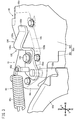
- FIG. 3 is an enlarged perspective view around the bracket of FIGS. 1 and 2. It is an expansion perspective view of a modification. It is an expansion perspective view of a modification.
- the electric vehicle 10 is an electric scooter having a floor portion 14 having a low floor, and rotationally drives the rear wheels 16 by a driving force of a motor 20 incorporated in a swing arm 18 (unit swing) that pivotally supports the rear wheels 16. Run by.
- the electric vehicle 10 according to the present embodiment is not limited to the electric scooter shown in FIG. 1, and can be applied to various electric saddle type vehicles driven by the motor 20. In the following description, a scooter type electric vehicle 10 will be described.
- the side frame portions 32L and 32R include rising portions 34L and 34R that extend obliquely upward and rearward from the pair of left and right underframe portions 30L and 30R, and a rear frame 36L that extends rearward from the pair of left and right rising portions 34L and 34R. And 36R.
- the pair of left and right rear frames 36L and 36R supports the seat 12 on which an occupant is seated from below.
- the rear ends of the pair of left and right rear frames 36L and 36R are connected by a tail pipe portion 38.
- ⁇ Front forks 40L and 40R are attached to the head pipe 26 in a steerable manner.
- a handlebar 44 is attached to the upper portions of the front forks 40L and 40R via a steering stem 42.
- Front wheels 46 are attached to the lower ends of the front forks 40L and 40R.
- a front fender 48 that covers the front wheel 46 from above is attached to the front forks 40L and 40R.
- a connection support portion 50 including a pivot bracket 50a is provided between the underframe portions 30L and 30R and the side frame portions 32L and 32R.
- the connection support portion 50 supports a pivot shaft 54 extending in the left-right direction (vehicle width direction) of the electric vehicle 10.
- a front end portion (one end portion) of the swing arm 18 is pivotally supported on the pivot shaft 54.
- the swing arm 18 extends from the pivot shaft 54 to the left side of the rear wheel 16 along the front-rear direction of the electric vehicle 10.
- the rear end (the other end) of the swing arm 18 supports the rear wheel 16.
- the pair of left and right floor side covers 74L and 74R are connected to the leg shield 72 and the seat lower cover 76, and cover the pair of left and right underframe portions 30L and 30R from both left and right sides.
- the rear side covers 78L and 78R are connected to the rear edge portion of the seat lower cover 76.
- a main stand 80 is arranged below the electric vehicle 10 and near the swing arm 18.
- a side stand 86 is provided near the left rising portion 34L.
- the characteristic configuration of the electric vehicle 10 is to avoid a collision between a device disposed below the electric vehicle 10, for example, the main stand 80 and a curb or the like existing in front of the electric vehicle 10 while the electric vehicle 10 is traveling.
- the present invention relates to a protective structure for the device. That is, unlike the engine-powered vehicle, the electric vehicle 10 does not have a muffler, and thus the above-described device may directly collide with a curb or the like while traveling. Therefore, in the present embodiment, the electric vehicle 10 is provided with a unique protection structure that replaces the muffler of the engine vehicle.
- the swing arm 18 has a swing arm body 98 (case).
- the swing arm main body 98 is a hollow member, and has one end portion 98a (wide portion) extending in the vehicle width direction in the space near the pivot shaft 54 in front of the rear wheel 16.
- the swing arm 18 extends from the left side of the one end 98a toward the left side of the rear wheel 16, and the motor 20 is housed in the extended portion.
- the one end portion 98a of the swing arm main body 98 constitutes the front end portion of the swing arm 18, and is pivotally supported by the pivot shaft 54.
- the pivot shaft 54 is supported by the vehicle body frame 22 via the connection support portion 50.
- the connection support portion 50 has a plurality of pivot brackets 50a that extend rearward from the pair of left and right rising portions 34L and 34R and support the pivot shaft 54.
- the one end 98a of the swing arm body 98 is a relatively wide portion of the swing arm 18 in the vehicle width direction.
- the one end portion 98a is composed of a rear portion 98r having a substantially constant width in the vehicle width direction and a substantially trapezoidal front portion 98f that spreads forward from the rear portion 98r. ..
- a connecting portion 98b extending rearward is provided on the left side of the rear portion 98r of the one end portion 98a.
- the connecting portion 98b connects the one end portion 98a and the housing portion of the motor 20 in the swing arm body 98 (the left portion of the rear wheel 16 in the swing arm 18).
- Extending portion 98c (narrow width portion) slightly extending rearward is provided on the right side of the rear portion 98r.
- the extending portion 98c is a portion that is narrower in the vehicle width direction than the one end portion 98a and the connecting portion 98b, and extends rearward between the one end portion 98a and the front end of the rear wheel 16. In this case, it is desirable that the right side surface of the rear portion 98r and the right side surface of the extending portion 98c are substantially flush with each other.
- Two projections 98e extend forward toward the pivot shaft 54 on both left and right sides of the front portion 98f of the one end 98a.
- the two protrusions 98e are pivotally supported by the pivot shaft 54.
- a bracket 100 made of a metal plate member is provided on the right side surface (the surface of the case) of the one end 98a and the extension 98c.
- the bracket 100 has a base end portion 100a, a protruding portion 100b, a tapered portion 100c, and a parallel portion 100d.
- the base end portion 100a extends in the front-rear direction along the right side surface of the rear portion 98r of the one end portion 98a and the right side surface of the extending portion 98c.
- the protruding portion 100b extends rightward (outward in the vehicle width direction) from the front portion of the base end portion 100a.
- the tapered portion 100c is inclined inward in the vehicle width direction so that the distance from the front end portion of the protruding portion 100b to the front side and the right side surface of the front portion 98f of the one end portion 98a (the right side surface that expands forward) is narrowed. And is extending.
- the parallel portion 100d extends forward substantially parallel to the right side surface of the front portion 98f while maintaining a constant gap H1 between the parallel portion 100d and the right side surface.
- the bracket 100 is formed into a shape shown in FIGS. 1 to 3 by sheet metal working, for example. Then, the base end portion 100a of the bracket 100 is fixed to the right side surface of the rear portion 98r of the one end portion 98a by the screw member 102, whereby the bracket 100 is fixed to the swing arm body 98.
- the main stand 80 has a shaft portion 80a, a stand portion 80b, a spring 80c and a pin 80d.
- the shaft portion 80a is a cylindrical member that penetrates the connecting portion 98b and the extending portion 98c of the swing arm body 98 and the base end portion 100a of the bracket 100 in the vehicle width direction.
- the stand portion 80b is a substantially U-shaped member in a bottom view of FIG. 2, and its base end portion is pivotally supported by the shaft portion 80a.
- the pin 80d is formed integrally with the base end portion 100a of the bracket 100, and protrudes rightward (outward in the vehicle width direction) from the extending portion 98c side of the base end portion 100a.
- the pin 80d is formed integrally with the base end 100a so as to project from the base end 100a.
- the pin 80d may be configured integrally with the base end portion 100a by penetrating the base end portion 100a from the rear portion 98r of the extension portion 98c or the one end portion 98a and protruding rightward.
- the spring 80c has one end connected to the right end of the stand 80b and the other end connected to the tip of the pin 80d.
- the main stand 80 can put the electric vehicle 10 in a standing state with both ends of the stand portion 80b oriented downward, as shown by the chain double-dashed line in FIG.
- the elastic force of the spring 80c causes the stand portion 80b to rotate clockwise about the pin 80d in FIG.
- the main stand 80 returns to the storage position shown by the solid line in FIG.
- the guard portion 104 for protecting the pin 80d is provided in front of the pin 80d, so that the pin 80d is appropriately protected from a curb or the like existing in front while the electric vehicle 10 is traveling.
- a portion of the bracket 100 arranged in front of the pin 80d is configured as the guard portion 104. That is, a part of the bracket 100 is used as the guard part 104.
- the protruding portion 100b, the tapered portion 100c, the parallel portion 100d, and the outer end portion 100e of the bracket 100, which is the tip portion of the protruding portion 100b, function as the guard portion 104.
- the outer end portion 100e projects outwardly in the vehicle width direction by a distance H2 from the tip portion of the pin 80d.
- the pin 80d is provided on the side of the narrow extending portion 98c, while at least a part of the guard portion 104, specifically, the tapered portion 100c and the parallel portion 100d, has a wide end portion 98a. Is arranged on the front portion 98f side of the.
- a triangle 106 having the right side surface of the front portion 98f of the one end portion 98a, the tapered portion 100c, and the protruding portion 100b as one side is formed.
- the electric vehicle 10 according to the present embodiment can be modified to the configurations (modifications) of FIGS. 4 and 5 in place of the configurations of FIGS. 1 to 3. 4 and 5, one or a plurality of ribs 108A and 108B are provided on the right side surface of the one end portion 98a of the swing arm body 98, and the ribs 108A and 108B are used as guard portions 104A and 104B. Therefore, in any of these modified examples, the guard parts 104A and 104B are formed integrally with the one end part 98a in front of the pin 80d.
- bent portion of the rib 108A which is a connecting portion between the protruding portion 110 and the tapered portion 112, is formed as an outer end portion 114 that protrudes rightward (outward in the vehicle width direction) from the tip end portion of the pin 80d.
- each rib 108B is a substantially triangular rib and extends forward along the right side surface of the rear portion 98r of the one end portion 98a and the right side surface of the front portion 98f. Further, the front portion of each rib 108B forms a tapered portion 116 that extends obliquely toward the inside in the vehicle width direction so that the distance between the rib 108B and the right side surface of the one end portion 98a decreases toward the front.
- each triangular rib 108B the apex protruding to the right is configured as an outer end portion 118 of the rib 108B. At least one outer end portion 118 of the three outer end portions 118 projects rightward from the tip end portion of the pin 80d.
- the three ribs 108B are provided at the one end 98a so that the outer end 118 of the middle rib 108B most protrudes rightward.
- the three ribs 108B may have substantially the same size. Further, the number and interval of the ribs 108B may be appropriately changed according to the specifications of the electric vehicle 10.
- the electric vehicle 10 is an electric vehicle in which a main stand 80 is provided below, and the main stand 80 includes a stand portion 80b that sets the electric vehicle 10 in an upright state, and one end portion of which is a stand portion 80b. It is composed of a spring 80c to be connected and a pin 80d that supports the other end of the spring 80c.
- the electric vehicle 10 further includes guard portions 104, 104A, 104B provided in front of the pin 80d and protecting the pin 80d.
- the guard parts 104, 104A, 104B have tapered parts 100c, 112, 116 that incline inward in the vehicle width direction toward the front of the electric vehicle 10.
- the guard portions 104, 104A, 104B are provided in front of the pin 80d of the main stand 80, and the guard portions 104, 104A, 104B have the tapered portions 100c, 112, 116.
- the guard portions 104, 104A, 104B have the tapered portions 100c, 112, 116.
- the curb and the like are repelled forward by the tapered portions 100c, 112, and 116, so that the pin 80d can be easily separated from the curb and the like.
- the outer end portions 100e, 114, 118 of the guard portions 104, 104A, 104B on the outer side in the vehicle width direction are located on the outer side in the vehicle width direction than the tip of the pin 80d on the outer side in the vehicle width direction. In this way, since the pin 80d does not project outward of the guard portions 104, 104A, 104B in the vehicle width direction, it is possible to reliably prevent a curb or the like from directly colliding with the pin 80d.
- the electric vehicle 10 further includes a bracket 100 configured integrally with the pin 80d.
- a part of the bracket 100 is configured as the guard part 104.
- the pin 80d and the guard portion 104 can be configured as an integral part, so that the number of parts of the electric vehicle 10 can be reduced.
- the bracket 100 is fixed to the swing arm main body 98 (case) of the swing arm 18 (unit swing) included in the electric vehicle 10.
- a parallel portion 100d that is substantially parallel to the right side surface of the swing arm body 98 is provided in front of the tapered portion 100c of the bracket 100.
- the parallel portion 100d comes into contact with the right side surface of the swing arm main body 98 due to the collision force from the curb or the like, and the right side surface receives the collision force.
- the parallel portion 100d and the swing arm main body 98 both receive an impact force, the deformation of the guard portion 104 due to a collision can be suppressed. Further, by receiving the collision force on the surface, the stress is dispersed and the occurrence of stress concentration can be suppressed.
- a gap H1 is provided between the parallel portion 100d and the right side surface of the swing arm body 98.
- the swing arm main body 98 is provided with an extending portion 98c (narrow width portion) relatively narrow in the vehicle width direction and one end that is provided in front of the extending portion 98c and is wider in the vehicle width direction than the extending portion 98c. And a portion 98a (wide portion).
- the pin 80d is arranged on the extension part 98c side, and at least a part of the guard part 104 is arranged on the one end part 98a side.
- the swing arm main body 98 can protect the pin 80d. Further, since the pin 80d can be prevented from protruding outward of the guard portion 104 in the vehicle width direction, the pin 80d can be suitably protected by the guard portion 104.
- a triangle 106 is formed, with the right side surface of the swing arm body 98 and the tapered portion 100c as one side.
- the swing arm main body 98 is provided with a shaft portion 80a penetrating the swing arm main body 98 and the bracket 100 in the vehicle width direction.
- the base end portion of the stand portion 80b is pivotally supported by the shaft portion 80a. Thereby, the main stand 80 can be appropriately protected while the electric vehicle 10 is traveling.
- the bracket 100 is a plate-shaped member extending in the front-rear direction of the electric vehicle 10.
- the protruding portion 100b, the tapered portion 100c, the parallel portion 100d, and the outer end portion 100e, which are the front portion of the bracket 100, are configured as the guard portion 104.
- the pin 80d is connected to the rear end portion 100a of the bracket 100 in the vehicle width direction.
- the bracket 100 can be easily formed by sheet metal processing or the like. As a result, the guard part 104 can be constructed at low cost.
- the guard portions 104A and 104B are formed integrally with the swing arm body 98 of the swing arm 18 provided in the electric vehicle 10, the number of parts of the electric vehicle 10 can be reduced. it can.
Landscapes
- Engineering & Computer Science (AREA)
- Mechanical Engineering (AREA)
- Axle Suspensions And Sidecars For Cycles (AREA)
- Automatic Cycles, And Cycles In General (AREA)
- Body Structure For Vehicles (AREA)
Abstract
電動車両(10)のメインスタンド(80)は、該電動車両(10)を起立状態にするスタンド部(80b)と、一端部がスタンド部(80b)に連結されるスプリング(80c)と、該スプリング(80c)の他端部を支持するピン(80d)とからなる。ピン(80d)の前方には、該ピン(80d)を保護するガード部(104)が設けられている。ガード部(104)は、電動車両(10)の前方に向かって車幅方向内側に傾斜するテーパ部(100c)を有する。
Description
本発明は、メインスタンドが下方に設けられた電動車両に関する。
自動二輪車の下方には、駐車時に該自動二輪車を起立状態にするメインスタンドが設けられている(例えば、特開平10-250655号公報及び特開平11-79022号公報参照)。
ところで、自動二輪車がエンジン駆動方式(エンジン車)から電動車両になると、エンジンの排気装置としてのマフラが不要となる。エンジン車の場合、該エンジン車の下方でマフラの内側に配置されたメインスタンド等の機器は、該マフラによって前方に存在する縁石等との衝突が避けられていた。一方、電動車両では、そのような機構が設けられていないため、独自の保護構造が必要となる。
そこで、本発明は、メインスタンド等の電動車両の下方に配置される機器と、縁石等との衝突を回避することが可能となる電動車両を提供することを目的とする。
本発明の態様は、メインスタンドが下方に設けられた電動車両であって、前記メインスタンドは、前記電動車両を起立状態にするスタンド部と、一端部が前記スタンド部に連結されるスプリングと、該スプリングの他端部を支持するピンとからなる。前記電動車両は、前記ピンの前方に設けられ、該ピンを保護するガード部をさらに備える。前記ガード部は、前記電動車両の前方に向かって車幅方向の内側に傾斜するテーパ部を有する。
本発明によれば、メインスタンドのピンの前方にガード部を設け、ガード部がテーパ部を有する。これにより、電動車両の走行中、前方に存在する縁石等は、テーパ部に直接衝突する。この場合、縁石等は、テーパ部によって前方に弾かれるので、ピンを縁石等から容易に離間させることができる。このように、本発明では、メインスタンド等の電動車両の下方に配置される機器と、縁石等との衝突を回避することが可能となる。
以下、本発明に係る電動車両の好適な実施形態について、添付の図面を参照しながら説明する。
[1.本実施形態に係る電動車両10の概略構成]
図1は、本実施形態に係る電動車両10の右側面図である。なお、以下の説明では、電動車両10のシート12に着座した乗員の見た方向に従って、前後、左右及び上下の方向を説明する。また、電動車両10において、左右一対に配設される構成要素については、左側の構成要素については「L」、右側の構成要素については「R」の文字を付けて説明する場合がある。
図1は、本実施形態に係る電動車両10の右側面図である。なお、以下の説明では、電動車両10のシート12に着座した乗員の見た方向に従って、前後、左右及び上下の方向を説明する。また、電動車両10において、左右一対に配設される構成要素については、左側の構成要素については「L」、右側の構成要素については「R」の文字を付けて説明する場合がある。
電動車両10は、低床のフロア部14を有する電動スクータであり、後輪16を軸支するスイングアーム18(ユニットスイング)に内蔵されたモータ20の駆動力で後輪16を回転駆動させることにより走行する。なお、本実施形態に係る電動車両10は、図1の電動スクータに限定されることはなく、モータ20によって駆動する各種の電動の鞍乗型車両に適用可能である。以下の説明では、スクータ型の電動車両10について説明する。
電動車両10は、車体フレーム22と、車体フレーム22を覆う合成樹脂製の車体カバー24とを有する。車体フレーム22は、前端部のヘッドパイプ26と、ヘッドパイプ26から後ろ斜め下方に延びるダウンパイプ28と、ダウンパイプ28の後端から後方に延びる左右一対のアンダーフレーム部30L、30Rと、アンダーフレーム部30L、30Rの後端から後ろ斜め上方に延びるサイドフレーム部32L、32Rとから構成される。サイドフレーム部32L、32Rは、左右一対のアンダーフレーム部30L、30Rから後ろ斜め上方に延びる立ち上げ部34L、34Rと、左右一対の立ち上げ部34L、34Rから後方に延出するリヤフレーム36L、36Rとから構成される。左右一対のリヤフレーム36L、36Rは、乗員が着座するシート12を下側から支持する。左右一対のリヤフレーム36L、36Rの後端は、テールパイプ部38で連結されている。
ヘッドパイプ26には、フロントフォーク40L、40Rが操舵自在に取り付けられている。フロントフォーク40L、40Rの上部には、ステアリングステム42を介して、ハンドル44が取り付けられている。フロントフォーク40L、40Rの下端には、前輪46が取り付けられている。フロントフォーク40L、40Rには、前輪46を上方から覆うフロントフェンダ48が取り付けられている。
アンダーフレーム部30L、30Rとサイドフレーム部32L、32Rとの間には、ピボットブラケット50aを含む連結支持部50が設けられている。連結支持部50は、電動車両10の左右方向(車幅方向)に延びるピボット軸54を支持する。ピボット軸54には、スイングアーム18の前端部(一端部)が軸支されている。スイングアーム18は、ピボット軸54から電動車両10の前後方向に沿って、後輪16の左側方に延びている。スイングアーム18の後端部(他端部)は、後輪16を支持する。
スイングアーム18は、後輪16の左側方にモータ20が配置されるように、該モータ20を内蔵する。従って、スイングアーム18は、スイング式のパワーユニットとして構成される。スイングアーム18の後端部と左側のリヤフレーム36Lとの間には、リヤクッション56が連結されている。また、リヤフレーム36L、36Rには、後輪16を上方から覆うリヤフェンダ58が取り付けられている。さらに、スイングアーム18には、リヤフェンダ58と後輪16との間で後輪16を上方から直接覆い、且つ、スイングアーム18と共に揺動可能な他のフェンダ60が取り付けられている。
車体カバー24は、車体フレーム22等を覆うカバーであって、フロントカバー68、ハンドルカバー70、レッグシールド72、フロアサイドカバー74L、74R、シート下カバー76及びリヤサイドカバー78L、78R等を有する。フロントカバー68は、ヘッドパイプ26等の車体フレーム22の前端部を前方から覆う。ハンドルカバー70は、フロントカバー68の上方で、ハンドル44の左右中央部を覆う。レッグシールド72は、フロントカバー68に接続され、ヘッドパイプ26及びダウンパイプ28を後方から覆う。シート下カバー76は、シート12下方の空間を前方から覆う。
左右一対のフロアサイドカバー74L、74Rは、レッグシールド72及びシート下カバー76に連結され、左右一対のアンダーフレーム部30L、30Rを左右両側から覆う。リヤサイドカバー78L、78Rは、シート下カバー76の後縁部に接続されている。
電動車両10の下方であって、スイングアーム18の近傍には、メインスタンド80が配設されている。また、左側の立ち上げ部34Lの近傍には、サイドスタンド86が配設されている。
[2.本実施形態の特徴的な構成]
次に、本実施形態に係る電動車両10の特徴的な構成について、図1~図3を参照しながら説明する。
次に、本実施形態に係る電動車両10の特徴的な構成について、図1~図3を参照しながら説明する。
電動車両10の特徴的な構成とは、電動車両10の走行中において、電動車両10の下方に配置されている機器、例えば、メインスタンド80と、前方に存在する縁石等との衝突を回避するための該機器の保護構造に関するものである。すなわち、電動車両10は、エンジン車と異なり、マフラが存在しないため、走行中、上記の機器と縁石等とが直接衝突する可能性がある。そこで、本実施形態では、電動車両10において、エンジン車のマフラに代わるような独自の保護構造が設けられている。
以下の説明では、一例として、メインスタンド80のピン80dの保護構造について説明する。なお、本実施形態では、該電動車両10の下方に配置されている他の機器に対しても、該保護構造を適用可能である。また、本実施形態では、前方の縁石に限らず、電動車両10の走行中、前方からの飛び石に対してもピン80d等の機器を保護することが可能である。
ここで、メインスタンド80を含む電動車両10の下方の構成について、より詳しく説明する。
図1~図3に示すように、スイングアーム18は、スイングアーム本体98(ケース)を有する。スイングアーム本体98は、内部が空洞の部材であって、後輪16の前方におけるピボット軸54近傍の空間で車幅方向に延びる一端部98a(幅広部)を有する。なお、スイングアーム18は、一端部98aの左側から後輪16の左側方に延出し、該延出部分にモータ20が収容されている。
スイングアーム本体98の一端部98aは、スイングアーム18の前端部を構成し、ピボット軸54に軸支されている。前述のように、ピボット軸54は、連結支持部50を介して車体フレーム22に支持されている。連結支持部50は、左右一対の立ち上げ部34L、34R側から後方に延びてピボット軸54を支持する複数のピボットブラケット50aを有する。
スイングアーム本体98の一端部98aは、スイングアーム18における車幅方向に比較的幅広の部分である。図2の底面視で、一端部98aは、車幅方向に略一定の幅を有する後方部分98rと、後方部分98rから前方に向かって拡開する略台形状の前方部分98fとから構成される。
一端部98aの後方部分98rの左側には、後方に向かって延びる連結部98bが設けられている。連結部98bは、一端部98aと、スイングアーム本体98におけるモータ20の収容部分(スイングアーム18における後輪16の左側部分)とを連結する。
後方部分98rの右側には、後方に向かって僅かに延びる延出部98c(幅狭部)が設けられている。延出部98cは、一端部98a及び連結部98bよりも車幅方向に幅狭の部分であり、一端部98aと後輪16の前端との間で、後方に延びている。この場合、後方部分98rの右側面と、延出部98cの右側面とは、略面一であることが望ましい。
一端部98aの前方部分98fの左右両側には、ピボット軸54に向かって、2つの突出部98eが前方に延びている。2つの突出部98eは、ピボット軸54に軸支されている。
一端部98a及び延出部98cの右側面(ケースの面)には、金属製の板状部材からなるブラケット100が設けられている。ブラケット100は、基端部100a、突出部100b、テーパ部100c及び平行部100dを有する。基端部100aは、一端部98aの後方部分98rの右側面と、延出部98cの右側面とに沿って前後方向に延びている。突出部100bは、基端部100aの前方部分から右方向(車幅方向外側)に延出する。テーパ部100cは、突出部100bの先端部から前方に向かって、一端部98aの前方部分98fの右側面(前方に拡開する右側面)との間隔が狭まるように、車幅方向内側に傾斜して延びている。平行部100dは、前方部分98fの右側面との間で一定の隙間H1を保ちながら、該右側面と略平行に前方に延びている。
この場合、ブラケット100は、例えば、板金加工によって、図1~図3に示す形状に形成される。そして、ブラケット100の基端部100aをネジ部材102によって一端部98aの後方部分98rの右側面に締付固定することで、該ブラケット100がスイングアーム本体98に固定される。
一方、メインスタンド80は、軸部80a、スタンド部80b、スプリング80c及びピン80dを有する。軸部80aは、スイングアーム本体98の連結部98b及び延出部98cと、ブラケット100の基端部100aとを、車幅方向に貫通する円柱状の部材である。スタンド部80bは、図2の底面視で、略U字状の部材であり、基端部分が軸部80aに軸支されている。
ピン80dは、ブラケット100の基端部100aと一体に構成され、該基端部100aの延出部98c側から右方向(車幅方向外側)に突出している。なお、ピン80dは、基端部100aから突出するように該基端部100aと一体に形成されている。あるいは、ピン80dは、延出部98c又は一端部98aの後方部分98rから基端部100aを貫通して右方向に突出することで、該基端部100aと一体に構成されてもよい。
スプリング80cは、一端部がスタンド部80bの右端部に連結され、他端部がピン80dの先端部に連結されている。
従って、図1に実線で示すメインスタンド80の収納位置において、乗員が足掛け80e(図2参照)に右足を掛け、足掛け80eを下方向に押圧すると、スプリング80cの弾発力に抗して、スタンド部80bがピン80dを中心に図1の反時計方向に回動する。これにより、メインスタンド80は、図1に二点鎖線で示すように、スタンド部80bの両端部が下方に指向した状態で、電動車両10を起立状態にすることができる。一方、乗員が右足で前方からスタンド部80bを押圧すると、スプリング80cの弾発力によって、スタンド部80bがピン80dを中心に図1の時計方向に回動する。これにより、メインスタンド80は、図1に実線で示す収納位置に戻る。
そして、電動車両10では、ピン80dの前方に該ピン80dを保護するためのガード部104を設けることにより、電動車両10の走行中、前方に存在する縁石等からピン80dを適切に保護する。
具体的に、ブラケット100のうち、ピン80dの前方に配置されている部分をガード部104として構成する。すなわち、ブラケット100の一部をガード部104として利用する。この場合、突出部100b、テーパ部100c及び平行部100dと、突出部100bの先端部分であるブラケット100の外端部100eとがガード部104として機能する。
外端部100eは、ピン80dの先端部よりも、車幅方向外側に距離H2だけ突出している。具体的に、ピン80dは、幅狭な延出部98c側に設けられ、一方で、ガード部104の少なくとも一部、具体的には、テーパ部100c及び平行部100dは、幅広の一端部98aの前方部分98f側に配置されている。これにより、図2及び図3に示すように、一端部98aの前方部分98fの右側面と、テーパ部100cと、突出部100bとをそれぞれ一辺とする三角形106が構成される。
従って、電動車両10の走行中、該電動車両10の下方において、前方に存在する縁石等は、ガード部104、例えば、テーパ部100cに直接衝突する。これにより、ピン80dに縁石等が直接衝突することを回避することができる。
[3.本実施形態の変形例]
本実施形態に係る電動車両10は、図1~図3の構成に代えて、図4及び図5の構成(変形例)に変更可能である。図4及び図5では、スイングアーム本体98の一端部98aの右側面に1又は複数のリブ108A、108Bを設け、該リブ108A、108Bをガード部104A、104Bとするものである。従って、これらの変形例では、いずれの場合も、ガード部104A、104Bは、ピン80dの前方で、一端部98aと一体に形成されている。
本実施形態に係る電動車両10は、図1~図3の構成に代えて、図4及び図5の構成(変形例)に変更可能である。図4及び図5では、スイングアーム本体98の一端部98aの右側面に1又は複数のリブ108A、108Bを設け、該リブ108A、108Bをガード部104A、104Bとするものである。従って、これらの変形例では、いずれの場合も、ガード部104A、104Bは、ピン80dの前方で、一端部98aと一体に形成されている。
図4の変形例では、スイングアーム本体98の一端部98aの右側面に1つのリブ108Aを設け、このリブ108Aをガード部104Aとして機能させる。リブ108Aは、略L字状のリブであって、一端部98aの後方部分98rの右側面から右方向(車幅方向外側)に突出する板状の突出部110と、該突出部110の上側部分から前方に向かって、一端部98aの前方部分98fの右側面との間隔が狭まるように、車幅方向内側に傾斜して延びるテーパ部112とから構成される。そのため、テーパ部112は、略三角形状に形成されている。また、突出部110とテーパ部112との連結部分であるリブ108Aの屈曲部分は、ピン80dの先端部よりも、右方向(車幅方向外側)に突出する外端部114として形成される。
これにより、図4の変形例では、電動車両10の走行中、該電動車両10の下方において、前方に存在する縁石等は、ガード部104Aを構成するテーパ部112に直接衝突する。この場合でも、ピン80dに縁石等が直接衝突することを回避することができる。
図5の変形例では、スイングアーム本体98の一端部98aの右側面に、前後方向に延びる3つのリブ108Bを上下方向に間隔を空けて設け、これらのリブ108Bをガード部104Bとして機能させる。各リブ108Bは、略三角形状のリブであって、一端部98aの後方部分98rの右側面及び前方部分98fの右側面に沿って前方に延びている。また、各リブ108Bの前方部分は、前方に向かって、一端部98aの右側面との間隔が狭まるように、車幅方向内側に傾斜して延びるテーパ部116を構成する。さらに、三角形状の各リブ108Bにおいて、右方向に突出する頂点は、リブ108Bの外端部118として構成される。3つの外端部118のうち、少なくとも1つの外端部118は、ピン80dの先端部よりも、右方向に突出している。
図5の変形例では、電動車両10の走行中、該電動車両10の下方において、前方に存在する縁石等は、ガード部104Bを構成する各リブ108Bのテーパ部116に直接衝突する。この場合でも、ピン80dに縁石等が直接衝突することを回避することができる。
なお、図5では、真ん中のリブ108Bの外端部118が右方向に最も突出するように、3つのリブ108Bが一端部98aに設けられている。この変形例では、3つのリブ108Bが略同じ大きさであってもよい。また、電動車両10の仕様に応じて、リブ108Bの個数や間隔を適宜変更してもよい。
[4.本実施形態の効果]
以上説明した本実施形態に係る電動車両10の効果について説明する。
以上説明した本実施形態に係る電動車両10の効果について説明する。
本実施形態に係る電動車両10は、メインスタンド80が下方に設けられた電動車両であって、メインスタンド80は、電動車両10を起立状態にするスタンド部80bと、一端部がスタンド部80bに連結されるスプリング80cと、該スプリング80cの他端部を支持するピン80dとからなる。この場合、電動車両10は、ピン80dの前方に設けられ、該ピン80dを保護するガード部104、104A、104Bをさらに備える。ガード部104、104A、104Bは、電動車両10の前方に向かって車幅方向内側に傾斜するテーパ部100c、112、116を有する。
このように、メインスタンド80のピン80dの前方にガード部104、104A、104Bを設け、ガード部104、104A、104Bがテーパ部100c、112、116を有する。これにより、電動車両10の走行中、前方に存在する縁石等は、テーパ部100c、112、116に直接衝突する。この場合、縁石等は、テーパ部100c、112、116によって前方に弾かれるので、ピン80dを縁石等から容易に離間させることができる。このように、本実施形態では、メインスタンド80等の電動車両10の下方に配置される機器と、縁石等との衝突を回避することが可能となる。
この場合、ガード部104、104A、104Bの車幅方向外側の外端部100e、114、118は、ピン80dの車幅方向外側の先端部よりも、車幅方向外側に位置する。このように、ピン80dがガード部104、104A、104Bよりも車幅方向外側に出っ張っていないので、縁石等がピン80dに直接衝突することを確実に回避することができる。
また、図1~図3のように、電動車両10は、ピン80dと一体に構成されるブラケット100をさらに備える。この場合、ブラケット100の一部がガード部104として構成される。これにより、ピン80d及びガード部104を一体部品として構成することができるので、電動車両10の部品点数を削減することができる。
また、ブラケット100は、電動車両10に備わるスイングアーム18(ユニットスイング)のスイングアーム本体98(ケース)に固定されている。この場合、ブラケット100におけるテーパ部100cの前方に、スイングアーム本体98の右側面と略平行な平行部100dを設ける。
これにより、縁石等がガード部104に衝突した際、縁石等からの衝突力で平行部100dがスイングアーム本体98の右側面に当接し、該右側面が衝突力を受ける。このように、平行部100d及びスイングアーム本体98の双方で衝撃力を受けるので、衝突によるガード部104の変形を抑制することができる。また、衝突力を面で受けることで、応力が分散され、応力集中の発生を抑制することができる。
また、平行部100dとスイングアーム本体98の右側面との間には、隙間H1が設けられている。これにより、比較的軽度の衝突である場合には、ガード部104のみで衝突力を受けることになるので、スイングアーム本体98に衝撃が伝わることを抑制することができる。なお、比較的大きな衝突である場合には、平行部100dが該右側面に当接するため、ガード部104及びスイングアーム本体98の双方で衝突力を受けることになる。
さらに、スイングアーム本体98は、車幅方向に相対的に狭い延出部98c(幅狭部)と、該延出部98cの前方に設けられ、延出部98cよりも車幅方向に広い一端部98a(幅広部)とを有する。この場合、ピン80dは、延出部98c側に配置され、ガード部104の少なくとも一部は、一端部98a側に配置される。
これにより、ガード部104に加え、スイングアーム本体98によってもピン80dを保護することができる。また、ピン80dがガード部104よりも車幅方向外側に出っ張らないようにすることができるので、ピン80dをガード部104で好適に保護することができる。
さらにまた、図2の底面視で、スイングアーム本体98の右側面とテーパ部100cとをそれぞれ一辺とする三角形106が構成される。これにより、最低限の角数で、電動車両10とガード部104との間に空間を設けつつ、ガード部104の機械的強度を確保することができる。
また、スイングアーム本体98には、該スイングアーム本体98及びブラケット100に対して車幅方向に貫通する軸部80aが設けられている。この場合、スタンド部80bの基端部分は、軸部80aに軸支されている。これにより、電動車両10の走行中、メインスタンド80を適切に保護することができる。
さらに、ブラケット100は、電動車両10の前後方向に延びる板状部材である。この場合、ブラケット100の前方部分である突出部100b、テーパ部100c、平行部100d及び外端部100eがガード部104として構成される。ピン80dは、ブラケット100の後方部分である基端部100aに対して、車幅方向に連結されている。
これにより、板金加工等によってブラケット100を容易に形成することができる。この結果、ガード部104を安価に構成することができる。
また、図4及び図5のように、ガード部104A、104Bが電動車両10に備わるスイングアーム18のスイングアーム本体98と一体に形成されていれば、電動車両10の部品点数を削減することができる。
以上、本発明について好適な実施形態を用いて説明したが、本発明の技術的範囲は、上記の実施形態の記載範囲に限定されることはない。上記の実施形態に、多様な変更又は改良を加えることが可能であることは、当業者に明らかである。そのような変更又は改良を加えた形態も、本発明の技術的範囲に含まれ得ることが、請求の範囲の記載から明らかである。また、請求の範囲に記載された括弧書きの符号は、本発明の理解の容易化のために添付図面中の符号に倣って付したものであり、本発明がその符号をつけた要素に限定されて解釈されるものではない。
Claims (10)
- メインスタンド(80)が下方に設けられた電動車両(10)において、
前記メインスタンド(80)は、前記電動車両(10)を起立状態にするスタンド部(80b)と、一端部が前記スタンド部(80b)に連結されるスプリング(80c)と、該スプリング(80c)の他端部を支持するピン(80d)とからなり、
前記電動車両(10)は、前記ピン(80d)の前方に設けられ、該ピン(80d)を保護するガード部(104、104A、104B)をさらに備え、
前記ガード部(104、104A、104B)は、前記電動車両(10)の前方に向かって車幅方向の内側に傾斜するテーパ部(100c、112、116)を有する、電動車両(10)。 - 請求項1記載の電動車両(10)において、
前記ガード部(104、104A、104B)の前記車幅方向の外端部(100e、114、118)は、前記ピン(80d)の前記車幅方向の先端部よりも、前記車幅方向の外側に位置する、電動車両(10)。 - 請求項1又は2記載の電動車両(10)において、
前記ピン(80d)と一体に構成されるブラケット(100)をさらに備え、
前記ブラケット(100)の一部が前記ガード部(104)である、電動車両(10)。 - 請求項3記載の電動車両(10)において、
前記ブラケット(100)は、前記電動車両(10)に備わるユニットスイング(18)のケース(98)に固定され、
前記ブラケット(100)における前記テーパ部(100c)の前方には、前記ケース(98)の面と略平行な平行部(100d)が設けられている、電動車両(10)。 - 請求項4記載の電動車両(10)において、
前記平行部(100d)と前記ケース(98)の面との間には、隙間(H1)が設けられている、電動車両(10)。 - 請求項4又は5記載の電動車両(10)において、
前記ケース(98)は、前記車幅方向に相対的に狭い幅狭部(98c)と、該幅狭部(98c)の前方に設けられ、前記幅狭部(98c)よりも前記車幅方向に広い幅広部(98a)とを有し、
前記ピン(80d)は、前記幅狭部(98c)に配置され、
前記ガード部(104)の少なくとも一部は、前記幅広部(98a)に配置されている、電動車両(10)。 - 請求項4~6のいずれか1項に記載の電動車両(10)において、
前記電動車両(10)の底面視で、前記ケース(98)の面と前記テーパ部(100c)とをそれぞれ一辺とする三角形(106)が構成される、電動車両(10)。 - 請求項4~7のいずれか1項に記載の電動車両(10)において、
前記ケース(98)には、該ケース(98)及び前記ブラケット(100)に対して前記車幅方向に貫通する軸部(80a)が設けられ、
前記スタンド部(80b)の基端部分は、前記軸部(80a)に軸支されている、電動車両(10)。 - 請求項3~8のいずれか1項に記載の電動車両(10)において、
前記ブラケット(100)は、前記電動車両(10)の前後方向に延びる板状部材であり、
前記ブラケット(100)の前方部分(100b~100e)が前記ガード部(104)として構成され、
前記ピン(80d)は、前記ブラケット(100)の後方部分(100a)で前記車幅方向に連結されている、電動車両(10)。 - 請求項1又は2記載の電動車両(10)において、
前記ガード部(104A、104B)は、前記電動車両(10)に備わるユニットスイング(18)のケース(98)と一体に形成されている、電動車両(10)。
Priority Applications (2)
| Application Number | Priority Date | Filing Date | Title |
|---|---|---|---|
| CN201980091399.XA CN113423632B (zh) | 2019-02-05 | 2019-11-07 | 电动车辆 |
| JP2020570370A JP7117401B2 (ja) | 2019-02-05 | 2019-11-07 | 電動車両 |
Applications Claiming Priority (2)
| Application Number | Priority Date | Filing Date | Title |
|---|---|---|---|
| JP2019-018592 | 2019-02-05 | ||
| JP2019018592 | 2019-02-05 |
Publications (1)
| Publication Number | Publication Date |
|---|---|
| WO2020161974A1 true WO2020161974A1 (ja) | 2020-08-13 |
Family
ID=71947609
Family Applications (1)
| Application Number | Title | Priority Date | Filing Date |
|---|---|---|---|
| PCT/JP2019/043725 Ceased WO2020161974A1 (ja) | 2019-02-05 | 2019-11-07 | 電動車両 |
Country Status (3)
| Country | Link |
|---|---|
| JP (1) | JP7117401B2 (ja) |
| CN (1) | CN113423632B (ja) |
| WO (1) | WO2020161974A1 (ja) |
Citations (6)
| Publication number | Priority date | Publication date | Assignee | Title |
|---|---|---|---|---|
| JPH0769255A (ja) * | 1993-08-31 | 1995-03-14 | Honda Motor Co Ltd | 自動二・三輪車におけるスタンドストッパ構造 |
| JPH09254840A (ja) * | 1996-03-19 | 1997-09-30 | Honda Motor Co Ltd | スクータ型車両のフレーム構造 |
| JP2011246021A (ja) * | 2010-05-28 | 2011-12-08 | Honda Motor Co Ltd | 鞍乗り型電動車両 |
| JP2015193351A (ja) * | 2014-03-31 | 2015-11-05 | 本田技研工業株式会社 | 鞍乗り型車両 |
| JP2017202701A (ja) * | 2016-05-09 | 2017-11-16 | スズキ株式会社 | 電動二輪車 |
| JP2018027771A (ja) * | 2016-08-10 | 2018-02-22 | 本田技研工業株式会社 | 自動二輪車におけるサイドスタンド構造 |
Family Cites Families (3)
| Publication number | Priority date | Publication date | Assignee | Title |
|---|---|---|---|---|
| JP2007223538A (ja) | 2006-02-24 | 2007-09-06 | Honda Motor Co Ltd | 自動二輪車 |
| CN206485506U (zh) * | 2016-12-30 | 2017-09-12 | 纳恩博(北京)科技有限公司 | 一种电动车辆及车辆支架 |
| CN107117228B (zh) * | 2017-07-03 | 2022-07-22 | 宁波鑫泰电气科技有限公司 | 电动双撑装置及车辆 |
-
2019
- 2019-11-07 WO PCT/JP2019/043725 patent/WO2020161974A1/ja not_active Ceased
- 2019-11-07 JP JP2020570370A patent/JP7117401B2/ja active Active
- 2019-11-07 CN CN201980091399.XA patent/CN113423632B/zh active Active
Patent Citations (6)
| Publication number | Priority date | Publication date | Assignee | Title |
|---|---|---|---|---|
| JPH0769255A (ja) * | 1993-08-31 | 1995-03-14 | Honda Motor Co Ltd | 自動二・三輪車におけるスタンドストッパ構造 |
| JPH09254840A (ja) * | 1996-03-19 | 1997-09-30 | Honda Motor Co Ltd | スクータ型車両のフレーム構造 |
| JP2011246021A (ja) * | 2010-05-28 | 2011-12-08 | Honda Motor Co Ltd | 鞍乗り型電動車両 |
| JP2015193351A (ja) * | 2014-03-31 | 2015-11-05 | 本田技研工業株式会社 | 鞍乗り型車両 |
| JP2017202701A (ja) * | 2016-05-09 | 2017-11-16 | スズキ株式会社 | 電動二輪車 |
| JP2018027771A (ja) * | 2016-08-10 | 2018-02-22 | 本田技研工業株式会社 | 自動二輪車におけるサイドスタンド構造 |
Also Published As
| Publication number | Publication date |
|---|---|
| CN113423632B (zh) | 2022-11-29 |
| JPWO2020161974A1 (ja) | 2021-11-25 |
| JP7117401B2 (ja) | 2022-08-12 |
| CN113423632A (zh) | 2021-09-21 |
Similar Documents
| Publication | Publication Date | Title |
|---|---|---|
| JP4308573B2 (ja) | 自動車のフロントアクスルに用いられるサブフレーム | |
| CN1927639B (zh) | 二轮机动车的冲击检测传感器安装结构 | |
| JP7450489B2 (ja) | 自動二輪車 | |
| JP4218815B2 (ja) | 鞍乗型車両用エアバック装置 | |
| JP6238952B2 (ja) | 鞍乗り型車両のライセンスプレート支持構造 | |
| JP3956705B2 (ja) | 鞍乗型不整地走行車両のブレーキ装置 | |
| WO2020161974A1 (ja) | 電動車両 | |
| JP5285554B2 (ja) | 鞍乗り型車両の車体構造 | |
| JP4757757B2 (ja) | フロントバンパー | |
| CN115520304B (zh) | 具有防护装置的个人移动设备 | |
| JP4474352B2 (ja) | 小型電動車両の操縦装置 | |
| JPWO2020065939A1 (ja) | 鞍乗り型車両のエアバッグ装置 | |
| JPH0274482A (ja) | フルカウル型自動二輪車におけるサイドバンパ装置 | |
| JP2007137192A (ja) | 小型電動車両のアクセル装置 | |
| JP2004276735A (ja) | フロントサブフレーム構造 | |
| EP3305642B1 (en) | Straddled vehicle | |
| JP4466123B2 (ja) | ステアリングラックマウント構造 | |
| JP2548698B2 (ja) | 鞍乗型車両の前フエンダ保護構造 | |
| CN103237720B (zh) | 骑乘式车辆 | |
| JP3461211B2 (ja) | 自動車のフレーム構造 | |
| JP4592466B2 (ja) | トラクタ | |
| JP7733488B2 (ja) | 車両前部構造 | |
| JP2974925B2 (ja) | 自転車用フェンダ、及び、自転車 | |
| JP4908126B2 (ja) | フロントフェンダ | |
| JP2008080884A (ja) | フロントバンパー |
Legal Events
| Date | Code | Title | Description |
|---|---|---|---|
| 121 | Ep: the epo has been informed by wipo that ep was designated in this application |
Ref document number: 19914199 Country of ref document: EP Kind code of ref document: A1 |
|
| ENP | Entry into the national phase |
Ref document number: 2020570370 Country of ref document: JP Kind code of ref document: A |
|
| NENP | Non-entry into the national phase |
Ref country code: DE |
|
| 122 | Ep: pct application non-entry in european phase |
Ref document number: 19914199 Country of ref document: EP Kind code of ref document: A1 |