WO2020158820A1 - アルミニウム系金属樹脂複合構造体、アルミニウム系金属部材、アルミニウム系金属部材の製造方法およびアルミニウム系金属樹脂複合構造体の製造方法 - Google Patents
アルミニウム系金属樹脂複合構造体、アルミニウム系金属部材、アルミニウム系金属部材の製造方法およびアルミニウム系金属樹脂複合構造体の製造方法 Download PDFInfo
- Publication number
- WO2020158820A1 WO2020158820A1 PCT/JP2020/003252 JP2020003252W WO2020158820A1 WO 2020158820 A1 WO2020158820 A1 WO 2020158820A1 JP 2020003252 W JP2020003252 W JP 2020003252W WO 2020158820 A1 WO2020158820 A1 WO 2020158820A1
- Authority
- WO
- WIPO (PCT)
- Prior art keywords
- aluminum
- based metal
- metal member
- resin
- composite structure
- Prior art date
Links
Images


Classifications
-
- B—PERFORMING OPERATIONS; TRANSPORTING
- B29—WORKING OF PLASTICS; WORKING OF SUBSTANCES IN A PLASTIC STATE IN GENERAL
- B29C—SHAPING OR JOINING OF PLASTICS; SHAPING OF MATERIAL IN A PLASTIC STATE, NOT OTHERWISE PROVIDED FOR; AFTER-TREATMENT OF THE SHAPED PRODUCTS, e.g. REPAIRING
- B29C65/00—Joining or sealing of preformed parts, e.g. welding of plastics materials; Apparatus therefor
- B29C65/70—Joining or sealing of preformed parts, e.g. welding of plastics materials; Apparatus therefor by moulding
-
- B—PERFORMING OPERATIONS; TRANSPORTING
- B29—WORKING OF PLASTICS; WORKING OF SUBSTANCES IN A PLASTIC STATE IN GENERAL
- B29C—SHAPING OR JOINING OF PLASTICS; SHAPING OF MATERIAL IN A PLASTIC STATE, NOT OTHERWISE PROVIDED FOR; AFTER-TREATMENT OF THE SHAPED PRODUCTS, e.g. REPAIRING
- B29C45/00—Injection moulding, i.e. forcing the required volume of moulding material through a nozzle into a closed mould; Apparatus therefor
- B29C45/14—Injection moulding, i.e. forcing the required volume of moulding material through a nozzle into a closed mould; Apparatus therefor incorporating preformed parts or layers, e.g. injection moulding around inserts or for coating articles
-
- B—PERFORMING OPERATIONS; TRANSPORTING
- B29—WORKING OF PLASTICS; WORKING OF SUBSTANCES IN A PLASTIC STATE IN GENERAL
- B29C—SHAPING OR JOINING OF PLASTICS; SHAPING OF MATERIAL IN A PLASTIC STATE, NOT OTHERWISE PROVIDED FOR; AFTER-TREATMENT OF THE SHAPED PRODUCTS, e.g. REPAIRING
- B29C45/00—Injection moulding, i.e. forcing the required volume of moulding material through a nozzle into a closed mould; Apparatus therefor
- B29C45/0001—Injection moulding, i.e. forcing the required volume of moulding material through a nozzle into a closed mould; Apparatus therefor characterised by the choice of material
-
- B—PERFORMING OPERATIONS; TRANSPORTING
- B29—WORKING OF PLASTICS; WORKING OF SUBSTANCES IN A PLASTIC STATE IN GENERAL
- B29C—SHAPING OR JOINING OF PLASTICS; SHAPING OF MATERIAL IN A PLASTIC STATE, NOT OTHERWISE PROVIDED FOR; AFTER-TREATMENT OF THE SHAPED PRODUCTS, e.g. REPAIRING
- B29C45/00—Injection moulding, i.e. forcing the required volume of moulding material through a nozzle into a closed mould; Apparatus therefor
- B29C45/0053—Injection moulding, i.e. forcing the required volume of moulding material through a nozzle into a closed mould; Apparatus therefor combined with a final operation, e.g. shaping
- B29C45/006—Joining parts moulded in separate cavities
- B29C45/0062—Joined by injection moulding
-
- B—PERFORMING OPERATIONS; TRANSPORTING
- B29—WORKING OF PLASTICS; WORKING OF SUBSTANCES IN A PLASTIC STATE IN GENERAL
- B29C—SHAPING OR JOINING OF PLASTICS; SHAPING OF MATERIAL IN A PLASTIC STATE, NOT OTHERWISE PROVIDED FOR; AFTER-TREATMENT OF THE SHAPED PRODUCTS, e.g. REPAIRING
- B29C45/00—Injection moulding, i.e. forcing the required volume of moulding material through a nozzle into a closed mould; Apparatus therefor
- B29C45/14—Injection moulding, i.e. forcing the required volume of moulding material through a nozzle into a closed mould; Apparatus therefor incorporating preformed parts or layers, e.g. injection moulding around inserts or for coating articles
- B29C45/14311—Injection moulding, i.e. forcing the required volume of moulding material through a nozzle into a closed mould; Apparatus therefor incorporating preformed parts or layers, e.g. injection moulding around inserts or for coating articles using means for bonding the coating to the articles
-
- B—PERFORMING OPERATIONS; TRANSPORTING
- B29—WORKING OF PLASTICS; WORKING OF SUBSTANCES IN A PLASTIC STATE IN GENERAL
- B29C—SHAPING OR JOINING OF PLASTICS; SHAPING OF MATERIAL IN A PLASTIC STATE, NOT OTHERWISE PROVIDED FOR; AFTER-TREATMENT OF THE SHAPED PRODUCTS, e.g. REPAIRING
- B29C45/00—Injection moulding, i.e. forcing the required volume of moulding material through a nozzle into a closed mould; Apparatus therefor
- B29C45/14—Injection moulding, i.e. forcing the required volume of moulding material through a nozzle into a closed mould; Apparatus therefor incorporating preformed parts or layers, e.g. injection moulding around inserts or for coating articles
- B29C45/14336—Coating a portion of the article, e.g. the edge of the article
-
- B—PERFORMING OPERATIONS; TRANSPORTING
- B29—WORKING OF PLASTICS; WORKING OF SUBSTANCES IN A PLASTIC STATE IN GENERAL
- B29C—SHAPING OR JOINING OF PLASTICS; SHAPING OF MATERIAL IN A PLASTIC STATE, NOT OTHERWISE PROVIDED FOR; AFTER-TREATMENT OF THE SHAPED PRODUCTS, e.g. REPAIRING
- B29C66/00—General aspects of processes or apparatus for joining preformed parts
- B29C66/70—General aspects of processes or apparatus for joining preformed parts characterised by the composition, physical properties or the structure of the material of the parts to be joined; Joining with non-plastics material
- B29C66/74—Joining plastics material to non-plastics material
- B29C66/742—Joining plastics material to non-plastics material to metals or their alloys
- B29C66/7422—Aluminium or alloys of aluminium
-
- C—CHEMISTRY; METALLURGY
- C23—COATING METALLIC MATERIAL; COATING MATERIAL WITH METALLIC MATERIAL; CHEMICAL SURFACE TREATMENT; DIFFUSION TREATMENT OF METALLIC MATERIAL; COATING BY VACUUM EVAPORATION, BY SPUTTERING, BY ION IMPLANTATION OR BY CHEMICAL VAPOUR DEPOSITION, IN GENERAL; INHIBITING CORROSION OF METALLIC MATERIAL OR INCRUSTATION IN GENERAL
- C23C—COATING METALLIC MATERIAL; COATING MATERIAL WITH METALLIC MATERIAL; SURFACE TREATMENT OF METALLIC MATERIAL BY DIFFUSION INTO THE SURFACE, BY CHEMICAL CONVERSION OR SUBSTITUTION; COATING BY VACUUM EVAPORATION, BY SPUTTERING, BY ION IMPLANTATION OR BY CHEMICAL VAPOUR DEPOSITION, IN GENERAL
- C23C22/00—Chemical surface treatment of metallic material by reaction of the surface with a reactive liquid, leaving reaction products of surface material in the coating, e.g. conversion coatings, passivation of metals
- C23C22/05—Chemical surface treatment of metallic material by reaction of the surface with a reactive liquid, leaving reaction products of surface material in the coating, e.g. conversion coatings, passivation of metals using aqueous solutions
- C23C22/06—Chemical surface treatment of metallic material by reaction of the surface with a reactive liquid, leaving reaction products of surface material in the coating, e.g. conversion coatings, passivation of metals using aqueous solutions using aqueous acidic solutions with pH less than 6
- C23C22/48—Chemical surface treatment of metallic material by reaction of the surface with a reactive liquid, leaving reaction products of surface material in the coating, e.g. conversion coatings, passivation of metals using aqueous solutions using aqueous acidic solutions with pH less than 6 not containing phosphates, hexavalent chromium compounds, fluorides or complex fluorides, molybdates, tungstates, vanadates or oxalates
- C23C22/56—Treatment of aluminium or alloys based thereon
-
- C—CHEMISTRY; METALLURGY
- C23—COATING METALLIC MATERIAL; COATING MATERIAL WITH METALLIC MATERIAL; CHEMICAL SURFACE TREATMENT; DIFFUSION TREATMENT OF METALLIC MATERIAL; COATING BY VACUUM EVAPORATION, BY SPUTTERING, BY ION IMPLANTATION OR BY CHEMICAL VAPOUR DEPOSITION, IN GENERAL; INHIBITING CORROSION OF METALLIC MATERIAL OR INCRUSTATION IN GENERAL
- C23C—COATING METALLIC MATERIAL; COATING MATERIAL WITH METALLIC MATERIAL; SURFACE TREATMENT OF METALLIC MATERIAL BY DIFFUSION INTO THE SURFACE, BY CHEMICAL CONVERSION OR SUBSTITUTION; COATING BY VACUUM EVAPORATION, BY SPUTTERING, BY ION IMPLANTATION OR BY CHEMICAL VAPOUR DEPOSITION, IN GENERAL
- C23C22/00—Chemical surface treatment of metallic material by reaction of the surface with a reactive liquid, leaving reaction products of surface material in the coating, e.g. conversion coatings, passivation of metals
- C23C22/73—Chemical surface treatment of metallic material by reaction of the surface with a reactive liquid, leaving reaction products of surface material in the coating, e.g. conversion coatings, passivation of metals characterised by the process
-
- C—CHEMISTRY; METALLURGY
- C23—COATING METALLIC MATERIAL; COATING MATERIAL WITH METALLIC MATERIAL; CHEMICAL SURFACE TREATMENT; DIFFUSION TREATMENT OF METALLIC MATERIAL; COATING BY VACUUM EVAPORATION, BY SPUTTERING, BY ION IMPLANTATION OR BY CHEMICAL VAPOUR DEPOSITION, IN GENERAL; INHIBITING CORROSION OF METALLIC MATERIAL OR INCRUSTATION IN GENERAL
- C23F—NON-MECHANICAL REMOVAL OF METALLIC MATERIAL FROM SURFACE; INHIBITING CORROSION OF METALLIC MATERIAL OR INCRUSTATION IN GENERAL; MULTI-STEP PROCESSES FOR SURFACE TREATMENT OF METALLIC MATERIAL INVOLVING AT LEAST ONE PROCESS PROVIDED FOR IN CLASS C23 AND AT LEAST ONE PROCESS COVERED BY SUBCLASS C21D OR C22F OR CLASS C25
- C23F1/00—Etching metallic material by chemical means
- C23F1/10—Etching compositions
- C23F1/14—Aqueous compositions
- C23F1/16—Acidic compositions
- C23F1/20—Acidic compositions for etching aluminium or alloys thereof
-
- B—PERFORMING OPERATIONS; TRANSPORTING
- B29—WORKING OF PLASTICS; WORKING OF SUBSTANCES IN A PLASTIC STATE IN GENERAL
- B29C—SHAPING OR JOINING OF PLASTICS; SHAPING OF MATERIAL IN A PLASTIC STATE, NOT OTHERWISE PROVIDED FOR; AFTER-TREATMENT OF THE SHAPED PRODUCTS, e.g. REPAIRING
- B29C45/00—Injection moulding, i.e. forcing the required volume of moulding material through a nozzle into a closed mould; Apparatus therefor
- B29C45/14—Injection moulding, i.e. forcing the required volume of moulding material through a nozzle into a closed mould; Apparatus therefor incorporating preformed parts or layers, e.g. injection moulding around inserts or for coating articles
- B29C45/14008—Inserting articles into the mould
-
- B—PERFORMING OPERATIONS; TRANSPORTING
- B29—WORKING OF PLASTICS; WORKING OF SUBSTANCES IN A PLASTIC STATE IN GENERAL
- B29K—INDEXING SCHEME ASSOCIATED WITH SUBCLASSES B29B, B29C OR B29D, RELATING TO MOULDING MATERIALS OR TO MATERIALS FOR MOULDS, REINFORCEMENTS, FILLERS OR PREFORMED PARTS, e.g. INSERTS
- B29K2023/00—Use of polyalkenes or derivatives thereof as moulding material
- B29K2023/10—Polymers of propylene
- B29K2023/12—PP, i.e. polypropylene
-
- B—PERFORMING OPERATIONS; TRANSPORTING
- B29—WORKING OF PLASTICS; WORKING OF SUBSTANCES IN A PLASTIC STATE IN GENERAL
- B29K—INDEXING SCHEME ASSOCIATED WITH SUBCLASSES B29B, B29C OR B29D, RELATING TO MOULDING MATERIALS OR TO MATERIALS FOR MOULDS, REINFORCEMENTS, FILLERS OR PREFORMED PARTS, e.g. INSERTS
- B29K2067/00—Use of polyesters or derivatives thereof, as moulding material
-
- B—PERFORMING OPERATIONS; TRANSPORTING
- B29—WORKING OF PLASTICS; WORKING OF SUBSTANCES IN A PLASTIC STATE IN GENERAL
- B29K—INDEXING SCHEME ASSOCIATED WITH SUBCLASSES B29B, B29C OR B29D, RELATING TO MOULDING MATERIALS OR TO MATERIALS FOR MOULDS, REINFORCEMENTS, FILLERS OR PREFORMED PARTS, e.g. INSERTS
- B29K2075/00—Use of PU, i.e. polyureas or polyurethanes or derivatives thereof, as moulding material
-
- B—PERFORMING OPERATIONS; TRANSPORTING
- B29—WORKING OF PLASTICS; WORKING OF SUBSTANCES IN A PLASTIC STATE IN GENERAL
- B29K—INDEXING SCHEME ASSOCIATED WITH SUBCLASSES B29B, B29C OR B29D, RELATING TO MOULDING MATERIALS OR TO MATERIALS FOR MOULDS, REINFORCEMENTS, FILLERS OR PREFORMED PARTS, e.g. INSERTS
- B29K2101/00—Use of unspecified macromolecular compounds as moulding material
- B29K2101/12—Thermoplastic materials
-
- B—PERFORMING OPERATIONS; TRANSPORTING
- B29—WORKING OF PLASTICS; WORKING OF SUBSTANCES IN A PLASTIC STATE IN GENERAL
- B29K—INDEXING SCHEME ASSOCIATED WITH SUBCLASSES B29B, B29C OR B29D, RELATING TO MOULDING MATERIALS OR TO MATERIALS FOR MOULDS, REINFORCEMENTS, FILLERS OR PREFORMED PARTS, e.g. INSERTS
- B29K2703/00—Use of resin-bonded materials for preformed parts, e.g. inserts
- B29K2703/04—Inorganic materials
- B29K2703/06—Metal powders, metal carbides or the like
-
- B—PERFORMING OPERATIONS; TRANSPORTING
- B29—WORKING OF PLASTICS; WORKING OF SUBSTANCES IN A PLASTIC STATE IN GENERAL
- B29K—INDEXING SCHEME ASSOCIATED WITH SUBCLASSES B29B, B29C OR B29D, RELATING TO MOULDING MATERIALS OR TO MATERIALS FOR MOULDS, REINFORCEMENTS, FILLERS OR PREFORMED PARTS, e.g. INSERTS
- B29K2705/00—Use of metals, their alloys or their compounds, for preformed parts, e.g. for inserts
- B29K2705/02—Aluminium
-
- C—CHEMISTRY; METALLURGY
- C23—COATING METALLIC MATERIAL; COATING MATERIAL WITH METALLIC MATERIAL; CHEMICAL SURFACE TREATMENT; DIFFUSION TREATMENT OF METALLIC MATERIAL; COATING BY VACUUM EVAPORATION, BY SPUTTERING, BY ION IMPLANTATION OR BY CHEMICAL VAPOUR DEPOSITION, IN GENERAL; INHIBITING CORROSION OF METALLIC MATERIAL OR INCRUSTATION IN GENERAL
- C23C—COATING METALLIC MATERIAL; COATING MATERIAL WITH METALLIC MATERIAL; SURFACE TREATMENT OF METALLIC MATERIAL BY DIFFUSION INTO THE SURFACE, BY CHEMICAL CONVERSION OR SUBSTITUTION; COATING BY VACUUM EVAPORATION, BY SPUTTERING, BY ION IMPLANTATION OR BY CHEMICAL VAPOUR DEPOSITION, IN GENERAL
- C23C22/00—Chemical surface treatment of metallic material by reaction of the surface with a reactive liquid, leaving reaction products of surface material in the coating, e.g. conversion coatings, passivation of metals
- C23C22/05—Chemical surface treatment of metallic material by reaction of the surface with a reactive liquid, leaving reaction products of surface material in the coating, e.g. conversion coatings, passivation of metals using aqueous solutions
- C23C22/68—Chemical surface treatment of metallic material by reaction of the surface with a reactive liquid, leaving reaction products of surface material in the coating, e.g. conversion coatings, passivation of metals using aqueous solutions using aqueous solutions with pH between 6 and 8
-
- C—CHEMISTRY; METALLURGY
- C23—COATING METALLIC MATERIAL; COATING MATERIAL WITH METALLIC MATERIAL; CHEMICAL SURFACE TREATMENT; DIFFUSION TREATMENT OF METALLIC MATERIAL; COATING BY VACUUM EVAPORATION, BY SPUTTERING, BY ION IMPLANTATION OR BY CHEMICAL VAPOUR DEPOSITION, IN GENERAL; INHIBITING CORROSION OF METALLIC MATERIAL OR INCRUSTATION IN GENERAL
- C23F—NON-MECHANICAL REMOVAL OF METALLIC MATERIAL FROM SURFACE; INHIBITING CORROSION OF METALLIC MATERIAL OR INCRUSTATION IN GENERAL; MULTI-STEP PROCESSES FOR SURFACE TREATMENT OF METALLIC MATERIAL INVOLVING AT LEAST ONE PROCESS PROVIDED FOR IN CLASS C23 AND AT LEAST ONE PROCESS COVERED BY SUBCLASS C21D OR C22F OR CLASS C25
- C23F1/00—Etching metallic material by chemical means
- C23F1/10—Etching compositions
- C23F1/14—Aqueous compositions
- C23F1/32—Alkaline compositions
- C23F1/36—Alkaline compositions for etching aluminium or alloys thereof
Definitions
- the present invention relates to an aluminum-based metal resin composite structure, an aluminum-based metal member, a method for manufacturing an aluminum-based metal member, and a method for manufacturing an aluminum-based metal-resin composite structure.
- Patent Document 1 An aluminum alloy is immersed in warm water to form a microporous hydroxyl group-containing dendritic layer having a thickness of 5 to 100 nm on the surface thereof, and then polybutylene phthalate or polyphenylene is formed on the treated surface.
- a technique has been proposed in which a thermoplastic resin mainly containing sulfide is injection-molded to integrate aluminum and the resin. According to this method, the surface of the aluminum alloy can be made microporous without using a chemical substance, and the resin can be strongly integrally bonded to the microporous surface, which is a technology that is very attractive in industry. ..
- the surface is formed with an opening of a hole having a number average inner diameter of 10 to 80 nm formed by an anodic oxidation method.
- a composite comprising a covered metal part and a resin composition part having a resin component composition containing 70 to 99% by weight of polyphenylene sulfide and 1 to 30% by weight of a polyolefin resin fixed to the above metal part by injection molding. Has been done.
- the inventors of the present invention faithfully complied with the content of the invention described in Patent Document 1 and verified the effect.
- the same aluminum alloy test piece was subjected to resin treatment under the same surface treatment condition and the same molding condition. Even when joined, it was confirmed that the joint between the aluminum alloy and the resin may show a joint strength with a high base metal fracture level, or the interface may fracture and the joint strength may not be exhibited at all. ing. That is, the mechanical properties of the composite produced by the method described in the document have a problem that the reproducibility of the effect of the invention is poor.
- the present invention has been made in view of the above circumstances, and can directly bond an aluminum-based metal member and a resin member made of a thermoplastic resin composition without using an adhesive, and an aluminum-based metal member.
- the present invention provides an aluminum-based metal-resin composite structure having excellent bonding strength between a resin member and a resin member.
- the present invention provides an aluminum-based metal member capable of stably obtaining an aluminum-based metal resin composite structure having excellent bonding strength between an aluminum-based metal member and a resin member, a method for producing the same, and an aluminum-based metal resin composite structure.
- a method of manufacturing a body is provided.
- the present inventors diligently studied to minimize the variation in the bonding strength between the aluminum-based metal and the resin in the aluminum-based metal-resin composite structure and to develop a stable bonding strength. As a result, they have found that the treated aluminum-based metal surface satisfies the specific microstructure requirements, and the stability of the bonding strength is significantly improved, and the present invention has been accomplished.
- the following aluminum-based metal-resin composite structure, aluminum-based metal member, method for manufacturing an aluminum-based metal member, and method for manufacturing an aluminum-based metal-resin composite structure are provided.
- An aluminum-based metal-resin composite structure comprising: Fourier transform infrared spectrophotometer (FTIR) analysis is performed on the surface of the aluminum-based metal member that is at least joined to the resin member, and the absorbance of the absorption peak observed at 3400 cm ⁇ 1 is A 1, and the absorbance at 3800 cm ⁇ 1 is when the absorbance at straight 3400 cm -1 which connects the absorbance at 2500 cm -1 was a 0, the absorbance difference (a 1 -A 0) is an aluminum-based metal-resin composite structure is in the range of 0.03 or less.
- FTIR Fourier transform infrared spectrophotometer
- An aluminum-based metal-resin composite structure wherein the average number density of the main trunks of the dendritic layer is 5/ ⁇ m or more and 40/ ⁇ m or less.
- An aluminum-based metal-resin composite structure comprising: An aluminum-based metal-resin composite structure, wherein the average number density of the main trunks of the dendritic layer is 5/ ⁇ m or more and 40/ ⁇ m or less.
- the average value of ten-point average roughness (R zjis ) measured according to JIS B0601:2001 (corresponding international standard: ISO4287) is more than 2 ⁇ m and 50 ⁇ m or less [6].
- An aluminum-based metal resin composite structure in which the surface of the aluminum-based metal member on which the dendritic layer is formed satisfies the following characteristic (2).
- the average value of the average lengths (RS m ) of roughness curve elements measured according to JIS B0601:2001 (corresponding international standard: ISO4287) is more than 10 ⁇ m and less than 400 ⁇ m [7].
- thermoplastic resin composition contains one or more thermoplastic resins selected from polyolefin-based resins, polyester-based resins, polyamide-based resins and polyarylene-based resins.
- An aluminum-based metal member having an absorbance difference (A 1 -A 0 ) of 0.03 or less, where A 0 is the absorbance at 3400 cm ⁇ 1 of the straight line connecting the two.
- the aluminum-based metal member according to any one of [8] to [10] above An aluminum-based metal member having an average thickness of the dendritic layer of 20 nm or more and less than 1000 nm, which is measured by observing a cross-sectional profile with a scanning electron microscope (SEM).
- SEM scanning electron microscope
- the aluminum-based metal member according to any one of [8] to [11] above, The surface of the aluminum-based metal member on which the dendritic layer is formed satisfies the following characteristic (1).
- the average value of ten-point average roughness (R zjis ) measured in accordance with JIS B0601:2001 (corresponding international standard: ISO4287) is more than 2 ⁇ m and 50 ⁇ m or less [13].
- the surface of the aluminum-based metal member on which the dendritic layer is formed satisfies the following characteristic (2).
- the average value of the average length (RS m ) of roughness curve elements measured according to JIS B0601:2001 (corresponding international standard: ISO4287) is more than 10 ⁇ m and less than 400 ⁇ m [14].
- the surface of the aluminum-based metal base material is chemically roughened by contacting the aluminum-based metal base material with an oxidizing acidic aqueous solution containing a metal cation having a standard electrode potential E 0 at ⁇ 25° C. of ⁇ 0.2 to 0.8.
- the method for manufacturing an aluminum-based metal member according to any one of [8] to [13] above including the step of: [15] The method for producing an aluminum-based metal member according to the above [14], wherein the oxidizing acidic aqueous solution contains cupric ions. [16] The method for producing an aluminum-based metal member according to [15], wherein the concentration of the cupric ion in the oxidizing aqueous solution is 1% by mass or more and 15% by mass or less. [17] The method for producing an aluminum-based metal member according to any one of the above [14] to [16], wherein the oxidizing acid in the oxidizing aqueous solution contains nitric acid.
- an aluminum-based metal member and a resin member made of a thermoplastic resin composition can be directly bonded without using an adhesive, and the bonding strength between the aluminum-based metal member and the resin member can be improved.
- An excellent aluminum-based metal resin composite structure can be provided.
- an aluminum-based metal member capable of stably obtaining an aluminum-based metal-resin composite structure having excellent bonding strength between an aluminum-based metal member and a resin member, a method for producing the same, and an aluminum-based metal A method for manufacturing a resin composite structure can be provided.
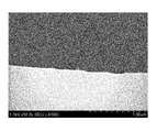
- FIG. 3 is a view showing an SEM cross-sectional profile of a joint portion of the aluminum-based metal resin composite structure obtained in Example 1.
- FIG. 5 is a diagram showing an SEM cross-sectional profile of a joint portion of an aluminum-based metal resin composite structure obtained in Comparative Example 1.
- FIG. 6 is a view showing an SEM cross-sectional profile of a joint portion of an aluminum-based metal resin composite structure obtained in Comparative Example 3.
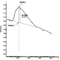
- FIG. 3 is a diagram conceptually showing a method for obtaining an absorbance difference (A 1 ⁇ A 0 ) according to the present invention from an FTIR chart.
- FIG. 3 is a diagram showing an SEM profile of the surface of the aluminum-based metal member obtained in Example 1.
- the aluminum-based metal resin composite structure 106 includes an aluminum-based metal member 103 having a dendritic layer 103-2 formed on at least a part of its surface, and an aluminum-based metal via the dendritic layer 103-2.
- a resin member 105 which is joined to the member 103 and is made of the thermoplastic resin composition (P).
- the dendritic layer 103-2 according to the present embodiment is a layer in which a plurality of branched trunks are forested.
- FIG. 1 is an external view showing an example of the structure of an aluminum-based metal resin composite structure 106 according to an embodiment of the present invention.
- FIG. 2 is a sectional view conceptually showing an example of the joint portion of the aluminum-based metal resin composite structure 106 according to the embodiment of the present invention.
- the aluminum-based metal member 103 that constitutes the aluminum-based metal-resin composite structure 106 is substantially the same as the aluminum-based metal member 103 before the resin member 105 is bonded in all points including the surface microstructure (morphology). .. That is, in the aluminum-based metal member 103 according to the present embodiment, the microstructure of the surface of the aluminum-based metal member 103 does not significantly change before and after the injection joining of the resin member 105, as will be described later in Examples. Therefore, in the present embodiment, unless otherwise specified, the aluminum-based metal member 103 is not only the aluminum-based metal member before the resin member 105 is joined, but also the aluminum-based metal-resin composite structure 106 to which the resin member 105 is joined. It also includes an aluminum-based metal member constituting the.
- the surface of the aluminum-based metal member 103 forming the aluminum-based metal-resin composite structure 106 according to the present embodiment at least the joint with the resin member 105 is analyzed by Fourier transform infrared spectrophotometer (FTIR) and observed at 3400 cm ⁇ 1.
- FTIR Fourier transform infrared spectrophotometer
- the lower limit of the absorbance difference (A 1 -A 0 ) is preferably 0.005 or more, more preferably 0.01 or more, and the upper limit of the absorbance difference (A 1 -A 0 ) is preferably 0.02 or less. is there.
- An example of a method for obtaining the difference in absorbance (A 1 ⁇ A 0 ) from the FTIR chart is shown in FIG. 7. Further, in the FTIR measurement, the high-sensitivity reflection method (RAS method) is adopted, and the incident angle of infrared light is 85°.
- the difference in absorbance by satisfying such a range, when the resin is insert-molded after the aluminum-based metal member is stored under environmental conditions, the composite of the composite with storage time. It is possible to prevent the phenomenon that the joint strength is lowered, that is, to extend the pot life.
- the broad absorption peak having a peak top at 3400 cm ⁇ 1 observed by FTIR measurement is estimated to be a peak due to aluminum hydroxide or aluminum hydrate oxide.
- the absorbance difference (A 1 -A 0 ) is an index showing the degree of possession of hydroxyl groups on the metal surface. There are still many unclear points regarding the relationship between the amount of hydroxyl groups on the metal surface and the bonding strength, but the present inventors consider it as follows.
- the average number density of the trunks of the dendritic layer 103-2 according to the present embodiment is 5 lines/ ⁇ m or more and 40 lines/ ⁇ m or less, preferably 7 lines/ ⁇ m or more, more preferably 10 lines/ ⁇ m or more, It is preferably 35 lines/ ⁇ m or less, more preferably 30 lines/ ⁇ m or less.
- the average number density of the trunks of the dendritic layer 103-2 according to the present embodiment is, for example, as shown in FIG. 8, a certain area is selected from the SEM photograph of the surface of the aluminum-based metal member 103, and the aluminum-based metal member is selected. It can be calculated by counting the “number of trunks” grown from the surface of 103 and converting it per unit length of the base.
- the average number density of the main trunks of the dendritic layer 103-2 according to the present embodiment can be measured at a total of 10 points in one measurement sample, and the average value thereof can be adopted.
- the aluminum-based metal-resin composite structure 106 it suffices to satisfy either one of the configuration relating to the difference in absorbance (A 1 -A 0 ) and the configuration relating to the average number density of the main trunk, It is preferable to satisfy both the configuration related to the difference (A 1 -A 0 ) and the configuration related to the average number density of the main trunks.
- the aluminum-based metal-resin composite structure 106 according to the present embodiment is excellent in the bonding strength between the aluminum-based metal member 103 and the resin member 105 because the dendritic layer 103-2 is present on the surface 104 of the bonded portion.
- the dendritic layer 103-2 is formed on the microscopic uneven structure of micron order, even if the metal etching amount when the fine uneven shape is formed by chemical etching is suppressed, the sufficient bonding strength is obtained.
- a dendritic layer is used when the resin member 105 is injection-molded on the aluminum-based metal member 103 in which the dendritic layer 103-2 is formed on a microscopic uneven structure. It was found that it is possible to significantly reduce the mold temperature as compared with the case where 103-2 does not exist. This property is effectively used for reducing the warpage due to the molding shrinkage of the injection molded body.
- the average thickness of the dendritic layer 103-2 calculated from the cross-sectional profile by a scanning electron microscope (SEM) is, for example, 20 nm or more and less than 1000 nm, preferably 30 nm or more and 900 nm or less. Yes, it is more preferably 50 nm or more and 800 nm or less, and further preferably 100 nm or more and 700 nm or less.
- SEM scanning electron microscope
- the aluminum-based metal-resin composite structure 106 maintains high bonding strength and suppresses deterioration of surface characteristics even when stored for a long period of time. That is, the pot life can be further extended.
- Such excellent properties for example, when preparing a metal-resin composite structure by a method described below by insert molding of a resin member onto a roughened metal member, a certain amount of roughened metal member is prepared at once. Every time it is used, it may be used one after another within the pot life, and it is free from the troublesome process that the roughened metal member has to be prepared immediately before each molding.
- the aluminum-based metal base surface on which the dendritic layer 103-2 is formed that is, the base surface on which the dendritic layer 103-2 is formed is flat. It may be a curved surface, an uneven surface, or a planar shape of the aluminum-based metal product itself, and is not particularly limited.
- the surface of the aluminum-based metal member 103 according to the present embodiment on which the dendritic layer 103-2 is formed is preferably any three straight line portions in parallel relationship and any three straight line portions orthogonal to the three straight line portions. The following six characteristics (1) and (2) are satisfied, and more preferably the following requirements (1) and (2) are simultaneously satisfied for a total of 6 straight line sections.
- the dendritic layer 103-2 is formed on a rough surface of micron order that simultaneously satisfies the following requirements (1) and (2).
- a rough surface is referred to as a double rough surface, and may be distinguished from a rough surface (single rough surface) in which the dendritic layer 103-2 is formed on the commercially available aluminum-based metal surface itself.
- the micron-order rough surface serving as the base may be called a base rough surface
- the dendritic layer coated on the base rough surface may be called a fine rough surface.
- the average value of ten-point average roughness (R zjis ) measured in accordance with JIS B0601:2001 (corresponding international standard: ISO4287) is more than 2 ⁇ m and 50 ⁇ m or less, preferably 5 ⁇ m to 30 ⁇ m, more preferably 8 To 25 ⁇ m, more preferably 10 to 20 ⁇ m.
- the ten-point average roughness of the mean value of the (R zjis) is the average value of R Zjis any 6 straight portions described above.
- the average value of the average lengths (RS m ) of roughness curve elements measured in accordance with JIS B0601:2001 (corresponding international standard: ISO4287) is more than 10 ⁇ m and less than 400 ⁇ m, preferably 50 ⁇ m to 350 ⁇ m. It is preferably in the range of 70 ⁇ m to 330 ⁇ m, more preferably 70 ⁇ m to 250 ⁇ m, and even more preferably 70 ⁇ m to 230 ⁇ m.
- the average length of the roughness curve element average value of (RS m) is the mean value of RS m any 6 straight portions described above.
- the bonding strength of the aluminum-based metal resin composite obtained from this is higher than the bonding strength of the aluminum-based metal resin composite obtained from the single rough surface. There is. Further, in the aluminum-based metal-resin composite obtained from the double roughened surface, even if the metal etching amount at the time of producing the base roughened surface is reduced, it is possible to suppress the tendency of the bonding strength to be reduced, which leads to a reduction in the metal loss amount, which is economical. Target. Furthermore, when the aluminum-based metal-resin composite is manufactured by insert molding, the mold temperature can be significantly reduced by using the double rough surface as compared with the case of using the single rough surface. As a result, it becomes possible to suppress the amount of warpage/deformation of the composite taken out after the mold is opened during the process from the mold temperature to the ambient temperature.
- FIG. 6 is a schematic diagram for explaining a total of 6 straight line portions including any 3 straight line portions in parallel relationship and any 3 straight line portions orthogonal to the 3 straight line portions on the joint surface 104 of the metal member 103. It is a figure.
- 6 straight line portions for example, 6 straight line portions B1 to B6 as shown in FIG. 6 can be selected.
- the center line B1 passing through the center portion A of the joint surface 104 of the metal member 103 is selected.
- straight lines B2 and B3 parallel to the center line B1 are selected.
- a center line B4 orthogonal to the center line B1 is selected, and straight lines B5 and B6 orthogonal to the center line B1 and parallel to the center line B4 are selected.
- the vertical distances D1 to D4 between the straight lines are, for example, 2 to 5 mm.
- the surface roughening treatment is generally performed not only on the joint surface 104 in the surface 110 of the metal member 103 but also on the entire surface 110 of the metal member 103.
- 6 straight line portions are selected from the same surface as the joint surface 104 of the metal member 103, other than the joint surface 104. Good.
- thermoplastic resin composition (P) forming the resin member 105 penetrates into the dendritic layer formed on the surface 110 of the aluminum-based metal member 103. It is obtained by joining an aluminum metal and a resin to form an aluminum metal resin interface.
- thermoplastic resin composition (P) penetrates into the dendritic layer on the surface 110 of the aluminum-based metal member 103, the physical resistance force between the aluminum-based metal member 103 and the resin member 105 ( It is considered that the aluminum-based metal member 103 and the resin member 105 made of the thermoplastic resin composition (P), which are normally difficult to bond, can be firmly bonded to each other by effectively expressing the (anchor effect).
- the aluminum-based metal-resin composite structure 106 thus obtained can prevent moisture and humidity from entering the interface between the aluminum-based metal member 103 and the resin member 105. That is, the airtightness and the liquidtightness at the adhesion interface of the aluminum-based metal resin composite structure 106 can be improved.
- the aluminum-based metal member 103 preferably has a specific surface area of 0.01 m 2 /g or more and 1.0 m 2 /g or less by the BET three-point method in nitrogen adsorption, and 0.05 m 2 /g. More preferably, it is 0.5 m 2 /g or less.
- the specific surface area is within the above range, the amount of the resin member 105 penetrating into the aluminum-based metal member 103 increases, so that the bonding strength between the resin member 105 and the aluminum-based metal member 103 can be further improved.
- Each member constituting the aluminum-based metal resin composite structure 106 will be described below.
- the aluminum-based metal member 103 according to this embodiment is obtained by roughening a commercially available aluminum-based metal base material by a method described below to provide a rough surface.
- Examples of commercially available aluminum-based metal base materials include an aluminum base material composed of a simple substance of aluminum and an aluminum alloy base material composed of an aluminum alloy. More specifically, examples of the aluminum-based metal base material include industrial pure aluminum (aluminum simple substance) 1000 series, Al—Cu series 2000 series alloy, Al—Mn series 3000 series alloy, and Al—Si.
- alloy numbers 1050, 1100, 2014, 2024, 3003, 5052, 6063, 7075 and the like are preferably used.
- the shape of the aluminum-based metal base material that is the raw material of the aluminum-based metal member 103 is not particularly limited as long as it can be joined to the resin member 105, and is, for example, a flat plate shape, a curved plate shape, a rod shape, a cylindrical shape, a lump shape, or the like. can do. Further, it may be a structure composed of a combination thereof. Further, the shape of the surface of the metal base material forming the joint surface 104 to be joined to the resin member 105 is not particularly limited, and examples thereof include a flat surface and a curved surface.
- the aluminum-based metal member 103 is processed into the above-described predetermined shape by cutting the aluminum-based metal base material, plastic working by pressing or the like, punching, cutting, polishing, electric discharge machining, or the like, and then the rough shape described later. Those that have been subjected to a chemical treatment are preferable. In short, it is preferable to use those processed into various shapes by various processing methods.
- the resin member 105 is made of a thermoplastic resin composition (P).
- the thermoplastic resin composition (P) contains a thermoplastic resin (A) as a resin component and, if necessary, a filler (B). Furthermore, the thermoplastic resin composition (P) contains other compounding agents as needed. Note that, for convenience, even when the resin member 105 is made of only the thermoplastic resin (A), it is described that the resin member 105 is made of the thermoplastic resin composition (P).
- thermoplastic resin (A) is not particularly limited, for example, a polyolefin resin, a polymethacrylic resin such as polymethylmethacrylate resin, a polyacrylic resin such as polymethylacrylate resin, a polystyrene resin, a polyvinyl alcohol-polyethylene resin Vinyl chloride copolymer resin, polyvinyl acetal resin, polyvinyl butyral resin, polyvinyl formal resin, polymethylpentene resin, maleic anhydride-styrene copolymer resin, polycarbonate resin, polyphenylene ether resin, polyether ether ketone resin, polyether ketone Aromatic polyether ketone such as resin, polyester resin, polyamide resin, polyamideimide resin, polyimide resin, polyetherimide resin, styrene elastomer, polyolefin elastomer, polyurethane elastomer, polyester elastomer, polyamide elast
- thermoplastic resin (A) from the viewpoint that a high bonding strength between the aluminum-based metal member 103 and the resin member 105 can be obtained more stably, a polyolefin-based resin, polyester-based resin, polyamide One or two or more thermoplastic resins selected from the group-based resins and the polyarylene-based resins are preferably used.
- the thermoplastic resin composition (P) may further contain the filler (B) from the viewpoint of adjusting the difference in linear expansion coefficient between the aluminum-based metal member 103 and the resin member 105 and improving the mechanical strength of the resin member 105.
- the filler (B) for example, one kind or two or more kinds can be selected from the group consisting of glass fiber, carbon fiber, carbon particles, clay, talc, silica, mineral and cellulose fiber. Of these, one or more selected from glass fiber, carbon fiber, talc and mineral are preferable.
- the shape of the filler (B) is not particularly limited, and may be any shape such as fibrous shape, particle shape, and plate shape.
- the filler (B) preferably contains a filler having a maximum length in the range of 10 nm or more and 600 ⁇ m or less in a fraction of 5 to 100%.
- the maximum length is more preferably 30 nm or more and 550 ⁇ m or less, still more preferably 50 nm or more and 500 ⁇ m or less.
- the fraction of the filler (B) in the range of the maximum length is preferably 10 to 100%, more preferably 20 to 100%.
- the filler (B) can easily move in the thermoplastic resin (A) melted during the molding of the thermoplastic resin composition (P).
- the filler (B) can be present in the vicinity of the surface of the aluminum-based metal member 103 at a certain ratio. Therefore, as described above, the resin that interacts with the filler (B) enters the uneven shape of the surface of the aluminum-based metal member 103, so that stronger bonding strength can be obtained.
- the thermoplastic resin composition (P) has a sufficient number of the filler (B) to act on the irregular shape of the surface of the aluminum-based metal member 103. It will exist inside.
- thermoplastic resin composition (P) contains the filler (B)
- its content is preferably 1 part by mass or more and 100 parts by mass or less with respect to 100 parts by mass of the thermoplastic resin (A).
- thermoplastic resin composition (P) may contain other compounding agents for the purpose of imparting individual functions.
- compounding agents include heat stabilizers, antioxidants, pigments, weathering agents, flame retardants, plasticizers, dispersants, lubricants, mold release agents, antistatic agents, and the like.
- thermoplastic resin composition (P) contains other compounding agents
- the content thereof is preferably 0.0001 to 5 parts by mass, more preferably 100 parts by mass of the thermoplastic resin (A). Is 0.001 to 3 parts by mass.
- thermoplastic resin composition (P) The method for preparing the thermoplastic resin composition (P) is not particularly limited, and the thermoplastic resin composition (P) can be prepared by a generally known method. For example, the following method may be mentioned. First, the above-mentioned thermoplastic resin (A), if necessary the above-mentioned filler (B), and further, if necessary, the above-mentioned other compounding agents are added to a Banbury mixer, a single-screw extruder, a twin-screw extruder, a high-speed twin-screw extrusion. The thermoplastic resin composition (P) is obtained by mixing or melt mixing using a mixing device such as a machine.
- a mixing device such as a machine.
- the aluminum-based metal member 103 is classified into a double rough surface and a single rough surface as described above.
- the double rough surface is formed by imparting a base rough surface having a microscopic uneven structure on the surface 110 of the metal member 103 using a known method such as a chemical etching agent, an anodic oxidation method, or a mechanical cutting method, and then the base rough surface. It can be formed by providing a fine rough surface on top.
- the single rough surface can be formed on a commercially available aluminum-based metal substrate by a method of immediately providing a fine rough surface without providing a base rough surface. The method for forming the double rough surface will be described in detail below as an example.
- the base rough surface having a microscopic uneven structure on the order of microns can be formed by a known metal surface roughening method.
- a chemical treatment method; an anodization method; a mechanical cutting method such as sand blasting, knurling, or laser processing can be used.
- These known methods can be used alone or in appropriate combination.
- treatment with an acid-based etching agent is preferable.
- the treatment methods disclosed in International Publication No. 2015/8847, Japanese Patent Application Laid-Open No. 2001-348684, International Publication No. 2008/81933 can be used.
- the treatment with the zinc ion-containing alkaline aqueous solution when added before the treatment with the acid-based etching agent, the airtightness of the joint surface of the metal/resin composite structure 106 is improved, and the surface of the roughened metal is smoothed. This is preferable because it can prevent the phenomenon that the property is impaired.
- the treatment with the zinc ion-containing alkaline aqueous solution for example, the treatment method disclosed in WO 2013/47365 can be adopted.
- a particularly preferable method for forming the base rough surface having the fine concavo-convex structure on the surface 110 of the metal member 103 is to carry out the following steps (1) to (4) in this order.
- Pretreatment Step This is a step of removing a coating film made of an oxide film, a hydroxide or the like existing on the surface of the metal member 103 on the side where the metal member 103 is joined to the resin member 105.
- mechanical polishing or chemical polishing is performed.
- an alkaline aqueous solution such as an aqueous sodium hydroxide solution or an aqueous potassium hydroxide solution or degreasing may be performed.
- Post-treatment step This is a cleaning step performed after the above step (3). It usually consists of washing and drying operations. An ultrasonic cleaning operation may be included to remove smut.
- the metal member provided with the base rough surface having the fine uneven structure of the micron order obtained by the above method has the standard electrode potential E 0 at ⁇ 25° C. of more than ⁇ 0.2 and 0.8 or less, preferably 0 or less.
- a fine roughened surface is provided by chemically roughening the surface of the metal member by bringing it into contact with an oxidizing acidic aqueous solution containing more than 0.5 or less metal cation. Further, it is preferable that the oxidizing acidic aqueous solution does not contain a metal cation having E 0 of ⁇ 0.2 or less. Specific examples of the metal cation whose standard electrode potential E 0 at ⁇ 25° C.
- Cu 2+ is preferable from the viewpoint of the rarity of metals and the safety and toxicity of the corresponding metal salts.
- the compound that generates Cu 2+ include inorganic compounds such as copper hydroxide, cupric oxide, cupric chloride, cupric bromide, copper sulfate, and copper nitrate, and these compounds are limited in the present invention. Although it can be used without any use, copper oxide is preferably used from the viewpoint of the safety and toxicity of the inorganic compound and the efficiency of providing the dendritic layer.
- nitric acid or an acid obtained by mixing nitric acid with hydrochloric acid, hydrofluoric acid or sulfuric acid can be exemplified.
- the concentration of nitric acid forming the aqueous solution is, for example, 10% by mass to 40% by mass, preferably 15% by mass to It is 38% by mass, more preferably 20% by mass to 35% by mass.
- the concentration of copper ions (cupric ion) forming the aqueous solution is, for example, 1% by mass to 15% by mass, preferably 2% by mass to 12% by mass, and more preferably 2% by mass to 8% by mass. If the nitric acid concentration is less than 10% by mass, the copper ions may not be completely dissolved, which is not preferable. If the nitric acid concentration exceeds 40% by mass, the viscosity of the aqueous solution itself increases, so that a sufficient roughening effect is obtained on the metal surface. In some cases, it cannot be given, and it is not preferable in terms of safety.
- the roughening efficiency of the metal may not be sufficient, which may lead to a decrease in bonding strength in the case of a composite. If it exceeds 15% by mass, the cupric oxide will not be sufficiently dissolved and the metal It is not preferable because it may leave a red copper residue on the surface.
- the temperature at the time of contacting the metal member provided with the base rough surface having a microscopic uneven structure of micron order and the oxidizing acidic aqueous solution containing the above metal cation is not particularly limited, but it is an economical speed while controlling the exothermic reaction.
- a treatment temperature of, for example, room temperature to 60° C., preferably 30° C. to 50° C. is adopted.
- the processing time at this time is, for example, in the range of 1 minute to 15 minutes, preferably 2 minutes to 10 minutes.
- the aluminum-based metal member thus formed, which has a fine rough surface on the base rough surface, is washed with water and dried as necessary to provide the aluminum-based metal member 103 for resin bonding.
- the aluminum-based metal member 103 obtained by the above method is inserted into the cavity of the injection molding die, and then the thermoplastic resin is applied to the injection molding die. It can be obtained by molding the resin member 105 by an injection molding method of injecting the composition (P). Specifically, this manufacturing method includes the following steps [1] to [3].
- Step of preparing desired thermoplastic resin composition (P) [2] Step of installing aluminum-based metal member 103 obtained by the above method inside a mold for injection molding [3] Injection molding machine A step of forming a resin member 105 by injection molding the thermoplastic resin composition (P) into the mold so as to be in contact with the aluminum-based metal member 103 using
- thermoplastic resin composition (P) The steps for preparing the thermoplastic resin composition (P) are as described above. Hereinafter, the injection molding method by the steps [2] and [3] will be described. First, a mold for injection molding is prepared, the mold is opened, and the aluminum-based metal member 103 is installed on a part of the mold. Thereafter, the mold is closed, and a step [in the mold is performed so that at least a part of the thermoplastic resin composition (P) is in contact with the formation region of the dendritic layer 103-2 on the surface 110 of the aluminum-based metal member 103. 1] The thermoplastic resin composition (P) obtained in 1] is injected and solidified. After that, the mold is opened and released to obtain the aluminum-based metal resin composite structure 106.
- injection foam molding and high-speed heat cycle molding for rapidly heating and cooling the mold may be used in combination with the injection molding in the steps [2] and [3].
- Injection foam molding methods include adding a chemical foaming agent to the resin, directly injecting nitrogen gas or carbon dioxide into the cylinder of the injection molding machine, or injecting nitrogen gas or carbon dioxide in a supercritical state.
- MuCell injection foam molding method in which the resin member 105 is a foam
- an aluminum-based metal resin composite structure 106 in which the resin member 105 is a foam can be obtained.
- ⁇ High-speed heat cycle molding can be performed by connecting a rapid heating and cooling device to the mold.
- the rapid heating/cooling device may be a generally used system.
- a heating method any one of a steam type, a pressurized hot water type, a hot water type, a hot oil type, an electric heater type, an electromagnetic induction heating type, or a combination thereof can be used.
- a cooling method either one of a cold water system and a cold oil system or a combination thereof can be used.
- the conditions of the high-speed heat cycle molding method include, for example, heating the injection mold to a temperature of 100° C. or higher and 250° C. or lower, and after the injection of the thermoplastic resin composition (P) is completed, the injection mold is It is desirable to cool.
- the temperature for heating the mold has a preferable range depending on the thermoplastic resin (A) constituting the thermoplastic resin composition (P), and is 100° C. for a crystalline resin having a melting point of less than 200° C. It is preferably 150° C. or higher, and is 140° C. or higher and 250° C. or lower if it is a crystalline resin and a thermoplastic resin having a melting point of 200° C. or higher. About amorphous resin, 100 degreeC or more and 180 degrees C or less are desirable.
- the aluminum-based metal-resin composite structure 106 according to this embodiment has high productivity and a high degree of freedom in shape control, it can be applied to various applications. Furthermore, since the aluminum-based metal resin composite structure 106 according to the present embodiment exhibits high airtightness and liquid-tightness, it is suitable for use according to these characteristics.
- structural parts for vehicles For example, structural parts for vehicles, vehicle-mounted products, housings for electronic devices, housings for home appliances, structural parts, mechanical parts, various automotive parts, electronic device parts, furniture, kitchen appliances, etc. , Medical equipment, building material parts, other structural parts, exterior parts, and the like.
- the following parts are designed so that the aluminum-based metal supports the parts where the strength is insufficient with resin alone.
- instrument panels, console boxes, door knobs, door trims, shift levers, pedals, glove boxes, bumpers, bonnets, fenders, trunks, doors, roofs, pillars, seats, radiators, oil pans, steering wheels, An ECU box, electrical components, etc. are mentioned.
- building materials and furniture include glass window frames, handrails, curtain rails, chests, drawers, closets, bookcases, desks, chairs, and the like.
- precision electronic parts include connectors, relays, gears, and the like.
- examples of the shipping container include a shipping container, a suitcase, a trunk, and the like.
- the aluminum-based metal member 103 in combination with the high thermal conductivity of the aluminum-based metal member 103 and the adiabatic property of the resin member 105, it is used for parts used in equipment for optimally designing heat management, for example, for various home appliances and various cooling devices.
- household appliances such as refrigerators, washing machines, vacuum cleaners, microwave ovens, air conditioners, lighting equipment, electric water heaters, TVs, watches, ventilation fans, projectors, speakers, personal computers, mobile phones, smartphones, digital cameras, tablets.
- Examples include a portable computer, a portable music player, a portable game machine, a charger, an electronic information device such as a battery, a cooling unit for a heating element such as a CPU or a lithium ion secondary battery.
- the contact area between the aluminum-based metal member 103 and the resin member 105 is increased, and the thermal resistance of the contact interface is reduced. It comes from being able to.
- toys sports equipment, shoes, sandals, bags, forks and knives, spoons, tableware such as plates, ballpoint pens and mechanical pencils, files, binders and other stationery, frying pans, pots, kettles, and fly-backs.
- tableware such as plates, ballpoint pens and mechanical pencils, files, binders and other stationery, frying pans, pots, kettles, and fly-backs.
- Examples include a ladle, a ladle, a whisk, cooking tools such as tongs, parts for a lithium-ion secondary battery, and a robot.
- Example 1 (Surface roughening process) An aluminum alloy plate having an alloy number A5052 (thickness: 2.0 mm) defined in JIS H4000 was cut into a length of 45 mm and a width of 18 mm. After degreasing this aluminum alloy plate, the treatment tank 1 filled with an alkaline etching agent (30° C.) containing 19.0% by mass of sodium hydroxide and 3.2% by mass of zinc oxide was used for 2 minutes. After soaking (sometimes abbreviated as “zinc pretreatment” in the following description), the plate was washed with water.
- an alkaline etching agent (30° C.) containing 19.0% by mass of sodium hydroxide and 3.2% by mass of zinc oxide was used for 2 minutes. After soaking (sometimes abbreviated as “zinc pretreatment” in the following description), the plate was washed with water.
- the obtained aluminum alloy plate was treated with an acid-based etching aqueous solution containing 3.9 mass% ferric chloride, 0.2 mass% cupric chloride, and 4.1 mass% sulfuric acid.
- the filled processing tank 2 was dipped and rocked at 30° C. for 6 minutes (may be abbreviated as “processing 1” in the following description). Then, ultrasonic cleaning (in water, 1 minute) was performed with running water.
- the aluminum alloy plate thus treated is treated with an acid system containing 6.3% by mass of cupric oxide (5.0% by mass as Cu 2+ ) and 30.0% by mass of nitric acid.
- the treatment tank 3 filled with an etching aqueous solution was dipped at 40° C. for 5 minutes and rocked (in some cases, it may be abbreviated as “treatment 2” in the following description). Then, after washing with running water, it was dried at 80° C. for 15 minutes to obtain an aluminum alloy plate.
- the standard electrode potential E 0 of Cu 2+ used in the process 2 is +0.337 (V vs. SHE).
- the surface roughness of the obtained surface-treated aluminum alloy plate is measured according to JIS B0601 (corresponding ISO4287) using a surface roughness measuring device "Surfcom 1400D (manufactured by Tokyo Seimitsu Co., Ltd.)".
- the ten-point average roughness (R zjis ) and the average length of roughness curve elements (RS m ) were measured.
- the average value of R zjis was 14 ⁇ m
- the average value of RS m was 135 ⁇ m.
- the R zjis average value and the RS m average value are averages of the measured values at 6 points at different measurement locations.
- the measurement was performed on a total of 6 straight line portions including any 3 straight line portions on the joint surface 104 of the metal member 103 and any 3 straight line portions orthogonal to the straight line portions. It is a thing.
- the conditions for measuring the surface roughness are as follows. ⁇ Stylus tip radius: 5 ⁇ m ⁇ Reference length: 0.8 mm ⁇ Evaluation length: 4 mm ⁇ Measurement speed: 0.06 mm/sec
- the specific surface area of the obtained surface-treated aluminum alloy plate was measured by the following method. As a result, the specific surface area was 0.21 m 2 /g.
- FTIR Shimadzu Fourier transform infrared spectrophotometer
- RAS-8000 high-sensitivity reflection measuring device
- a 0 the virtual absorbance at the absorbance of the absorption peak A 1, 3800 cm -1 absorbance and 2500cm straight 3400 cm -1 connecting the absorbance -1 observed in 3400 cm -1 .
- the absorbance difference (A 1 ⁇ A 0 ) value was 0.01.
- the SEM profile of the surface of the obtained surface-treated aluminum alloy plate is shown in FIG. According to this, the average number density of the main trunks of the dendritic layer was calculated to be 28/ ⁇ m.
- the average number density of the main trunks of the dendritic layer was measured at a total of 10 points in one measurement sample, and the average value thereof was adopted.
- the storage stability of the surface-treated aluminum alloy plate was examined by the following method. First, three sets of five surface-treated aluminum alloy plates that were doubly enclosed in a zippered plastic bag (product name: Unipack) so that they did not overlap each other were prepared. Then, the three sets of inclusion bodies were stored in a thermo-hygrostat at 40° C. and 90% RH. Five aluminum alloy plates were taken out from the aluminum alloy plate before set (0th day) and the aluminum alloy plate encapsulant after storage for 14 days, 28 days, and 56 days, and the aluminum-based metal resin was subjected to the injection molding process described later. Five samples of the composite structure were manufactured.
- the shear strength of the five aluminum-based metal resin composite structures was measured by the method described below, and the average value was used as the bonding strength. As a result, it was found that the bonding strength of the sample after storage for 56 days was within 5% from the bonding strength of the sample before setting.
- the average thickness of the dendritic layer was calculated to be 500 nm. It was confirmed that the nano-order dendritic layer was covering so as to follow the uneven shape of the micron order.
- the dendritic layer was also observed in the SEM analysis of the surface of the aluminum alloy plate before injection molding as described above (see FIG. 8), and its average thickness was 490 nm.
- the average thickness of the dendritic layer was obtained from a cross-sectional SEM photograph of the aluminum-based metal member before injection molding, unless otherwise specified.
- Example 2 The same operation as in Example 1 was carried out except that an aluminum alloy plate with alloy number A2024 was used instead of the aluminum alloy plate with alloy number A5052 specified in JIS H4000. The results are summarized in Table 1.
- Example 3 The same operation as in Example 1 was performed except that an aluminum alloy plate with alloy number A6063 was used instead of the aluminum alloy plate with alloy number A5052 specified in JIS H4000. The results are summarized in Table 1.
- Example 4 As the resin composition (P) used in the injection molding step, instead of glass fiber reinforced polypropylene (V7100 manufactured by Prime Polymer Co., Ltd.), glass fiber reinforced polyamide 6 (GM1011G30 manufactured by Toray Co.; glass fiber content 30% by mass, in the table) The same operation as in Example 1 was performed except that PA6 was used and the mold temperature during the injection molding process was 90°C. The results are summarized in Table 1.
- Example 5 The same operation as in Example 1 was performed except that the mold temperature during the injection molding process was lowered to 70°C. The results are summarized in Table 1.
- Example 6 The same operation as in Example 1 was performed except that the mold temperature during the injection molding process was raised to 120°C. The results are summarized in Table 1.
- Example 1 The same operation as in Example 6 was performed except that the treatment 2 was not performed. The results are summarized in Table 1.
- the etching amount As a result of measuring the etching amount, it was 8.0% by mass.
- the surface roughness was measured in the same manner as in the method described in Example 1 by using a surface roughness measuring device “Surfcom 1400D (manufactured by Tokyo Seimitsu Co., Ltd.)”, and the R zjis average value was 13 ⁇ m, and the RS m average value was measured. The value was 137 ⁇ m. Further, as a result of observing a cross-sectional SEM photograph of the surface-treated aluminum alloy plate, it was confirmed that the nano-order dendritic layer was covered so as to follow the uneven shape of the micron order. The average thickness of the dendritic layer was estimated to be 210 nm.
- Example 7 The same operation as in Example 1 was carried out except that the treatment 1 was not performed, to obtain a surface-treated aluminum alloy plate having a single rough surface. The results are summarized in Table 1. The surface-treated aluminum alloy plate was injection-molded in the same manner as in Example 1 to obtain an aluminum-based metal resin composite structure. The results are summarized in Table 1.
Landscapes
- Chemical & Material Sciences (AREA)
- Engineering & Computer Science (AREA)
- Mechanical Engineering (AREA)
- Manufacturing & Machinery (AREA)
- Chemical Kinetics & Catalysis (AREA)
- General Chemical & Material Sciences (AREA)
- Materials Engineering (AREA)
- Metallurgy (AREA)
- Organic Chemistry (AREA)
- Laminated Bodies (AREA)
- Injection Moulding Of Plastics Or The Like (AREA)
- ing And Chemical Polishing (AREA)
Abstract
Description
さらに、本発明はアルミニウム系金属部材と樹脂部材との接合強度に優れたアルミニウム系金属樹脂複合構造体を安定的に得ることが可能なアルミニウム系金属部材、その製造方法およびアルミニウム系金属樹脂複合構造体の製造方法を提供するものである。
表面の少なくとも一部に樹枝状層が形成されたアルミニウム系金属部材と、
上記樹枝状層を介して上記アルミニウム系金属部材に接合され、かつ、熱可塑性樹脂組成物からなる樹脂部材と、
を備えるアルミニウム系金属樹脂複合構造体であって、
上記アルミニウム系金属部材における少なくとも上記樹脂部材との接合部表面をフーリエ変換赤外線分光光度計(FTIR)分析し、3400cm-1に観測される吸収ピークの吸光度をA1とし、3800cm-1の吸光度と2500cm-1の吸光度とを結んだ直線の3400cm-1における吸光度をA0としたとき、吸光度差(A1-A0)が0.03以下の範囲であるアルミニウム系金属樹脂複合構造体。
[2]
上記[1]に記載のアルミニウム系金属樹脂複合構造体において、
上記樹枝状層の主幹の平均本数密度が5本/μm以上40本/μm以下であるアルミニウム系金属樹脂複合構造体。
[3]
表面の少なくとも一部に樹枝状層が形成されたアルミニウム系金属部材と、
上記樹枝状層を介して上記アルミニウム系金属部材に接合されている、熱可塑性樹脂組成物からなる樹脂部材と、
を備えるアルミニウム系金属樹脂複合構造体であって、
上記樹枝状層の主幹の平均本数密度が5本/μm以上40本/μm以下であるアルミニウム系金属樹脂複合構造体。
[4]
上記[1]乃至[3]のいずれか一つに記載のアルミニウム系金属樹脂複合構造体において、
走査型電子顕微鏡(SEM)による断面プロファイル観察から測定される、上記樹枝状層の平均厚みが20nm以上1000nm未満であるアルミニウム系金属樹脂複合構造体。
[5]
上記[1]乃至[4]のいずれか一つに記載のアルミニウム系金属樹脂複合構造体において、
上記アルミニウム系金属部材における上記樹枝状層が形成された表面が、下記特性(1)を満たすアルミニウム系金属樹脂複合構造体。
(1)JIS B0601:2001(対応国際規格:ISO4287)に準拠して測定される十点平均粗さ(Rzjis)の平均値が2μm超えて50μm以下である
[6]
上記[1]乃至[5]のいずれか一つに記載のアルミニウム系金属樹脂複合構造体において、
上記アルミニウム系金属部材における上記樹枝状層が形成された表面が、下記特性(2)を満たすアルミニウム系金属樹脂複合構造体。
(2)JIS B0601:2001(対応国際規格:ISO4287)に準拠して測定される粗さ曲線要素の平均長さ(RSm)の平均値が10μm超えて400μm未満である
[7]
上記[1]乃至[6]のいずれか一つに記載のアルミニウム系金属樹脂複合構造体において、
上記熱可塑性樹脂組成物が、ポリオレフィン系樹脂、ポリエステル系樹脂、ポリアミド系樹脂およびポリアリーレン系樹脂から選択される一種または二種以上の熱可塑性樹脂を含むアルミニウム系金属樹脂複合構造体。
[8]
熱可塑性樹脂組成物からなる樹脂部材との接合に用いられるアルミニウム系金属部材であって、
少なくとも上記樹脂部材との接合部表面に樹枝状層が形成されており、
上記アルミニウム系金属部材における上記接合部表面をフーリエ変換赤外線分光光度計(FTIR)分析し、3400cm-1に観測される吸収ピークの吸光度をA1とし、3800cm-1の吸光度と2500cm-1の吸光度とを結んだ直線の3400cm-1における吸光度をA0としたとき、吸光度差(A1-A0)が0.03以下の範囲であるアルミニウム系金属部材。
[9]
上記[8]に記載のアルミニウム系金属部材において、
上記樹枝状層の主幹の平均本数密度が5本/μm以上40本/μm以下であるアルミニウム系金属部材。
[10]
熱可塑性樹脂組成物からなる樹脂部材との接合に用いられるアルミニウム系金属部材であって、
少なくとも上記樹脂部材との接合部表面に樹枝状層が形成されており、
上記樹枝状層の主幹の平均本数密度が5本/μm以上40本/μm以下であるアルミニウム系金属部材。
[11]
上記[8]乃至[10]のいずれか一つに記載のアルミニウム系金属部材において、
走査型電子顕微鏡(SEM)による断面プロファイル観察から測定される、上記樹枝状層の平均厚みが20nm以上1000nm未満であるアルミニウム系金属部材。
[12]
上記[8]乃至[11]のいずれか一つに記載のアルミニウム系金属部材において、
上記アルミニウム系金属部材における上記樹枝状層が形成された表面が、下記特性(1)を満たすアルミニウム系金属部材。
(1)JIS B0601:2001(対応国際規格:ISO4287)に準拠して測定される十点平均粗さ(Rzjis)の平均値が2μm超えて50μm以下である
[13]
上記[8]乃至[12]のいずれか一つに記載のアルミニウム系金属部材において、
上記アルミニウム系金属部材における上記樹枝状層が形成された表面が、下記特性(2)を満たすアルミニウム系金属部材。
(2)JIS B0601:2001(対応国際規格:ISO4287)に準拠して測定される粗さ曲線要素の平均長さ(RSm)の平均値が10μm超えて400μm未満である
[14]
アルミニウム系金属基材を、25℃における標準電極電位E0が-0.2超え0.8以下である金属カチオンを含む酸化性酸性水溶液と接触させてアルミニウム系金属基材の表面を化学粗化する工程を含む上記[8]乃至[13]のいずれか一つに記載のアルミニウム系金属部材の製造方法。
[15]
上記酸化性酸性水溶液が第二銅イオンを含む上記[14]に記載のアルミニウム系金属部材の製造方法。
[16]
上記酸化性水溶液中の上記第二銅イオンの濃度が1質量%以上15質量%以下である上記[15]に記載のアルミニウム系金属部材の製造方法。
[17]
上記酸化性水溶液中の酸化性酸が硝酸を含む上記[14]乃至[16]のいずれか一つに記載のアルミニウム系金属部材の製造方法。
[18]
上記酸化性酸性水溶液が、上記E0が-0.2以下の金属カチオンを含まない上記[14]乃至[17]のいずれか一つに記載のアルミニウム系金属部材の製造方法。
[19]
上記[8]乃至[13]のいずれか一つに記載のアルミニウム系金属部材を射出成形金型にインサートし、次いで、上記射出成形金型に熱可塑性樹脂組成物を射出する工程を含むアルミニウム系金属樹脂複合構造体の製造方法。
さらに、本発明によれば、アルミニウム系金属部材と樹脂部材との接合強度に優れたアルミニウム系金属樹脂複合構造体を安定的に得ることが可能なアルミニウム系金属部材、その製造方法およびアルミニウム系金属樹脂複合構造体の製造方法を提供することができる。
本実施形態に係るアルミニウム系金属樹脂複合構造体106について説明する。
本実施形態に係るアルミニウム系金属樹脂複合構造体106は、表面の少なくとも一部に樹枝状層103-2が形成されたアルミニウム系金属部材103と、樹枝状層103-2を介してアルミニウム系金属部材103に接合され、かつ、熱可塑性樹脂組成物(P)からなる樹脂部材105と、を備える。
ここで、本実施形態に係る樹枝状層103-2は、複数に枝分かれした幹が林立した層をいう。本実施形態に係る樹枝状層103-2において、アルミニウム系金属部材103の表面から林立している幹を「主幹」といい、主幹から分かれた枝を「主枝」といい、主枝から分かれた枝を「側枝」と呼ぶ。
図1は、本発明に係る実施形態のアルミニウム系金属樹脂複合構造体106の構造の一例を示した外観図である。図2は、本発明に係る実施形態のアルミニウム系金属樹脂複合構造体106の接合部の一例を概念的に示した断面図である。
アルミニウム系金属樹脂複合構造体106を構成するアルミニウム系金属部材103は、表面微細組織(モルホロジー)を含む全ての点において、樹脂部材105が接合される前のアルミニウム系金属部材103に実質同一である。すなわち、本実施形態に係るアルミニウム系金属部材103は、後掲する実施例でも述べるように、樹脂部材105の射出接合前後でアルミニウム系金属部材103の表面の微細組織が大きく変化するものではない。したがって、本実施形態では、特に断らない限りアルミニウム系金属部材103とは、樹脂部材105を接合する前のアルミニウム系金属部材のみならず、樹脂部材105が接合されたアルミニウム系金属樹脂複合構造体106を構成するアルミニウム系金属部材をも包含するものである。
なお、吸光度差(A1-A0)をFTIRチャートから求める方法の例を図7に示した。また上記FTIR測定においては、高感度反射法(RAS法)を採用し、赤外光の入射角は85°である。
吸光度差(A1-A0)は金属表面の水酸基の保有程度を示す指標である。金属表面の水酸基量と接合強度の関係については未だ不明確な点が多いが本発明者らは以下のように考えている。すなわち金属表面上により多くの水酸基がある場合、環境中の水分を吸着しやすくなり表面に水分子層を形成し易くなり、特に、高湿度環境下で顕著である。この結果、金属樹脂間の接合強度が低下すると考えている。従って、吸光度差(A1-A0)を上記範囲に調整することにより、環境中の湿度の影響を受けにくく、可使時間を長くすることが可能となると同時に、得られる複合体も優れた接合強度を発現すると考えられる。
本実施形態に係る樹枝状層103-2の主幹の平均本数密度は、例えば、図8に示すように、アルミニウム系金属部材103の表面のSEM写真から一定のエリアを選択し、アルミニウム系金属部材103の表面から生えてきた「主幹の数」をカウントし、土台単位長さ当たりに換算することにより算出することができる。
本実施形態に係る樹枝状層103-2の主幹の平均本数密度は、一つの測定サンプルにおいて合計で10ヶ所測定し、それらの平均値を採用することができる。
本実施形態に係るアルミニウム系金属部材103における樹枝状層103-2が形成された表面は、好ましくは、平行関係にある任意の3直線部、および当該3直線部と直交する任意の3直線部からなる合計6直線部について、下記特性(1)および(2)のいずれかを満たし、より好ましくは下記要件(1)と(2)を同時に満たしている。換言すれば、本実施形態に係る樹枝状層103-2は、下記要件(1)と(2)を同時に満たすミクロンオーダーの粗面上に形成されていることが好ましい。以下このような粗面をダブル粗面と呼び、市販アルミニウム系金属表面そのものの上に樹枝状層103-2が形成された粗面(シングル粗面)と区別する場合がある。なおダブル粗面においては、土台となるミクロンオーダー粗面をベース粗面、該ベース粗面上に被覆された樹枝状層をファイン粗面と呼ぶ場合がある。
(2)JIS B0601:2001(対応国際規格:ISO4287)に準拠して測定される粗さ曲線要素の平均長さ(RSm)の平均値が10μm超えて400μm未満、好ましくは50μm~350μm、より好ましくは70μm~330μm、さらに好ましくは70μm~250μm、さらにより好ましくは70μm~230μmの範囲にある。なお、上記粗さ曲線要素の平均長さ(RSm)の平均値は、前述の任意の6直線部のRSmの平均値である。
上記6直線部は、例えば、図6に示すような6直線部B1~B6を選択することができる。まず、基準線として、金属部材103の接合部表面104の中心部Aを通る中心線B1を選択する。次いで、中心線B1と平行関係にある直線B2およびB3を選択する。次いで、中心線B1と直交する中心線B4を選択し、中心線B1と直交し、中心線B4と並行関係にある直線B5およびB6を選択する。ここで、各直線間の垂直距離D1~D4は、例えば、2~5mmである。
なお、通常、金属部材103の表面110中の接合部表面104だけでなく、金属部材103の表面110全体に対して表面粗化処理が施されている。金属部材103の表面110全体に対して表面粗化処理が施されている場合は、金属部材103の接合部表面104と同一面の、接合部表面104以外の箇所から6直線部を選択してもよい。
上記比表面積が上記範囲内であると、アルミニウム系金属部材103への樹脂部材105の侵入量が増えるため、樹脂部材105とアルミニウム系金属部材103との接合強度を一層向上させることができる。
以下、本実施形態に係るアルミニウム系金属部材103について説明する。
本実施形態に係るアルミニウム系金属部材103は、市販のアルミニウム系金属基材を後述する方法によって粗化して粗面を付与することによって得られる。市販のアルミニウム系金属基材としては、例えば、アルミニウム単体により構成されたアルミニウム基材、アルミニウム合金より構成されたアルミニウム合金基材等が挙げられる。
より具体的には、アルミニウム系金属基材としては、工業用純アルミニウム(アルミニウム単体)である1000系、Al-Cu系である2000系合金、Al-Mn系である3000系合金、Al-Si系である4000系合金、Al-Mg系である5000系合金、Al-Mg-Si系である6000系合金、Al-Zn-Mg系である7000系合金を例示できる。これらの中では、合金番号1050、1100、2014、2024、3003、5052、6063、7075等が好ましく用いられる。
また、樹脂部材105と接合する接合部表面104を構成する金属基材表面の形状は、特に限定されないが、例えば平面、曲面等が挙げられる。
以下、本実施形態に係る樹脂部材105について説明する。
樹脂部材105は熱可塑性樹脂組成物(P)からなる。熱可塑性樹脂組成物(P)は、樹脂成分として熱可塑性樹脂(A)と、必要に応じて充填材(B)と、含む。さらに、熱可塑性樹脂組成物(P)は必要に応じてその他の配合剤を含む。なお、便宜上、樹脂部材105が熱可塑性樹脂(A)のみからなる場合であっても、樹脂部材105は熱可塑性樹脂組成物(P)からなると記載する。
熱可塑性樹脂(A)としては特に限定されないが、例えば、ポリオレフィン系樹脂、ポリメタクリル酸メチル樹脂等のポリメタクリル系樹脂、ポリアクリル酸メチル樹脂等のポリアクリル系樹脂、ポリスチレン樹脂、ポリビニルアルコール-ポリ塩化ビニル共重合体樹脂、ポリビニルアセタール樹脂、ポリビニルブチラール樹脂、ポリビニルホルマール樹脂、ポリメチルペンテン樹脂、無水マレイン酸-スチレン共重合体樹脂、ポリカーボネート樹脂、ポリフェニレンエーテル樹脂、ポリエーテルエーテルケトン樹脂、ポリエーテルケトン樹脂等の芳香族ポリエーテルケトン、ポリエステル系樹脂、ポリアミド系樹脂、ポリアミドイミド樹脂、ポリイミド樹脂、ポリエーテルイミド樹脂、スチレン系エラストマー、ポリオレフィン系エラストマー、ポリウレタン系エラストマー、ポリエステル系エラストマー、ポリアミド系エラストマー、アイオノマー、アミノポリアクリルアミド樹脂、イソブチレン無水マレイン酸コポリマー、ABS、ACS、AES、AS、ASA、MBS、エチレン-塩化ビニルコポリマー、エチレン-酢酸ビニルコポリマー、エチレン-酢酸ビニル-塩化ビニルグラフトポリマー、エチレン-ビニルアルコールコポリマー、塩素化ポリ塩化ビニル樹脂、塩素化ポリエチレン樹脂、塩素化ポリプロピレン樹脂、カルボキシビニルポリマー、ケトン樹脂、非晶性コポリエステル樹脂、ノルボルネン樹脂、フッ素プラスチック、ポリテトラフルオロエチレン樹脂、フッ素化エチレンポリプロピレン樹脂、PFA、ポリクロロフルオロエチレン樹脂、エチレンテトラフルオロエチレンコポリマー、ポリフッ化ビニリデン樹脂、ポリフッ化ビニル樹脂、ポリアリレート樹脂、熱可塑性ポリイミド樹脂、ポリ塩化ビニリデン樹脂、ポリ塩化ビニル樹脂、ポリ酢酸ビニル樹脂、ポリサルホン樹脂、ポリパラメチルスチレン樹脂、ポリアリルアミン樹脂、ポリビニルエーテル樹脂、ポリフェニレンオキシド樹脂やポリフェニレンスルフィド(PPS)樹脂等のポリアリーレン系樹脂、ポリメチルペンテン樹脂、オリゴエステルアクリレート、キシレン樹脂、マレイン酸樹脂、ポリヒドロキシブチレート樹脂、ポリスルホン樹脂、ポリ乳酸樹脂、ポリグルタミン酸樹脂、ポリカプロラクトン樹脂、ポリエーテルスルホン樹脂、ポリアクリロニトリル樹脂、スチレン-アクリロニトリル共重合体樹脂等が挙げられる。これらの熱可塑性樹脂は一種単独で使用してもよいし、二種以上組み合わせて使用してもよい。
熱可塑性樹脂組成物(P)は、アルミニウム系金属部材103と樹脂部材105との線膨張係数差の調整や樹脂部材105の機械的強度を向上させる観点から、充填材(B)をさらに含んでもよい。
充填材(B)としては、例えば、ガラス繊維、炭素繊維、炭素粒子、粘土、タルク、シリカ、ミネラル、セルロース繊維からなる群から一種または二種以上を選ぶことができる。これらのうち、好ましくは、ガラス繊維、炭素繊維、タルク、ミネラルから選択される一種または二種以上である。
熱可塑性樹脂組成物(P)には、個々の機能を付与する目的でその他の配合剤を含んでもよい。このような配合剤としては、熱安定剤、酸化防止剤、顔料、耐候剤、難燃剤、可塑剤、分散剤、滑剤、離型剤、帯電防止剤等が挙げられる。
熱可塑性樹脂組成物(P)の調製方法は特に限定されず、一般的に公知の方法により調製することができる。例えば、以下の方法が挙げられる。まず、上記熱可塑性樹脂(A)、必要に応じて上記充填材(B)、さらに必要に応じて上記その他の配合剤を、バンバリーミキサー、単軸押出機、二軸押出機、高速二軸押出機等の混合装置を用いて、混合または溶融混合することにより、熱可塑性樹脂組成物(P)が得られる。
本実施形態に係るアルミニウム系金属部材103は、上記したようにダブル粗面とシングル粗面に分類される。ダブル粗面は、化学エッチング剤や陽極酸化法、機械的切削法等公知の方法を用いて金属部材103の表面110にミクロンオーダーの微細凹凸構造を持つベース粗面を付与し、次いでベース粗面上にファイン粗面を付与することによって形成することができる。シングル粗面は市販のアルミニウム系金属基材上にベース粗面を付与することなく直ちにファイン粗面を付与する方法で形成することができる。以下、ダブル粗面を例にとって、その形成方法を詳細に述べる。
ミクロンオーダーの微細凹凸構造を持つベース粗面は、公知の金属表面粗化方法によって形成することが可能である。例えば、薬液処理法;陽極酸化法;サンドブラスト、ローレット加工、レーザー加工等の機械的切削法等を挙げることができる。これらの公知方法は単独で、または適宜組み合わせて用いることができる。
これらの公知方法の中では、酸系エッチング剤による処理が好ましい。酸系エッチング剤を用いる公知処理方法としては、例えば国際公開第2015/8847号、特開2001-348684号公報、国際公開第2008/81933号等に開示された処理方法を採用することができる。
金属部材103における樹脂部材105との接合側の表面に存在する酸化膜や水酸化物等からなる被膜を除去する工程である。通常、機械研磨や化学研磨処理が行われる。接合側表面に機械油等の著しい汚染がある場合は、水酸化ナトリウム水溶液や水酸化カリウム水溶液等のアルカリ性水溶液による処理や、脱脂を行なってもよい。
(2)亜鉛イオン含有アルカリ水溶液による処理工程
水酸化アルカリ(MOH)と亜鉛イオン(Zn2+)とを重量比(MOH/Zn2+)1~100の割合で含む亜鉛イオン含有アルカリ水溶液中に、前処理後の金属部材103を浸漬し、金属部材表面に亜鉛含有被膜形成させる工程である。なお、前記MOHのMはアルカリ金属またはアルカリ土類金属である。
(3)酸系エッチング剤による処理工程
上記工程(2)終了後の金属部材103を、第二鉄イオンと第二銅イオンの少なくとも一方と、酸を含む酸系エッチング剤により処理して金属部材103の表面上の亜鉛含有被膜を溶離させると共に、ミクロンオーダーの微細凹凸形状を形成させる工程である。
(4)後処理工程
上記工程(3)の後に行われる洗浄工程である。通常は、水洗および乾燥操作からなる。スマット除去のために超音波洗浄操作を含めてもよい。
上の方法で得られた、ミクロンオーダーの微細凹凸構造を持つベース粗面が付与された金属部材は、次いで25℃における標準電極電位E0が-0.2超え0.8以下、好ましくは0超え0.5以下の金属カチオンを含む酸化性酸性水溶液と接触させて金属部材の表面を化学粗化することによってファイン粗面が付与される。また、上記酸化性酸性水溶液は、上記E0が-0.2以下の金属カチオンを含まないことが好ましい。
25℃における標準電極電位E0が-0.2超え0.8以下である金属カチオンとは、具体的にPb2+、Sn2+、Ag+、Hg2+、Cu2+等を例示することができる。これらの中では、金属の希少性の視点、対応金属塩の安全性・毒性の視点からはCu2+であることが好ましい。Cu2+を発生させる化合物としては、水酸化銅、酸化第二銅、塩化第二銅、臭化第二銅、硫酸銅、硝酸銅などの無機化合物を例示でき、これらの化合物は本発明において制限なく使用できるが、当該無機化合物の安全性、毒性の視点、樹枝状層の付与効率の視点からは酸化銅が好ましく用いられる。
酸化性酸性水溶液としては、硝酸または硝酸に対し塩酸、弗酸、硫酸のいずれかを混合した酸を例示することができる。さらに、過酢酸、過ギ酸に代表される過カルボン酸水溶液を用いてもよい。本実施形態において、酸化性酸性水溶液として硝酸を用い、金属カチオン発生化合物として酸化第二銅を用いる場合、水溶液を構成する硝酸濃度は、例えば10質量%~40質量%、好ましくは15質量%~38質量%、より好ましくは20質量%~35質量%である。また、水溶液を構成する銅イオン(第二銅イオン)濃度は、例えば1質量%~15質量%、好ましくは2質量%~12質量%、より好ましくは2質量%~8質量%である。硝酸濃度が10質量%未満では銅イオンが十分に溶解しきれない場合があるので好ましくなく、また40質量%を超える場合は水溶液そのものの粘性が上がるので金属面に対して十分な粗化効果を与えることができない場合があり、また安全性の点からも好ましくない。銅イオン濃度が1質量%未満では金属の粗化効率が十分でなく複合体とした場合の接合強度低下をもたらす恐れがあり、15質量%を超えると酸化第二銅が十分に溶解せず金属面上に赤い銅残渣を残す可能性があるので好ましくない。
このようにして形成された、ベース粗面上にファイン粗面を有するアルミニウム系金属部材は、必要に応じて水洗、乾燥処理が施されて樹脂接合用のアルミニウム系金属部材103が提供される。
本実施形態に係るアルミニウム系金属樹脂複合構造体106は、例えば、上記方法で得られたアルミニウム系金属部材103を射出成形金型のキャビティ部にインサートし、次いで、射出成形金型に熱可塑性樹脂組成物(P)を射出する射出成形法によって樹脂部材105を成形することによって得ることができる。
この製造方法は、具体的には、以下の[1]~[3]の工程を含んでいる。
[1]所望の熱可塑性樹脂組成物(P)を調製する工程
[2]上記方法で得られたアルミニウム系金属部材103を射出成形用の金型の内部に設置する工程
[3]射出成形機を用いて、アルミニウム系金属部材103と接するように上記金型内に熱可塑性樹脂組成物(P)を射出成形し、樹脂部材105を形成する工程
まず、射出成形用の金型を用意し、その金型を開いてその一部にアルミニウム系金属部材103を設置する。
その後、金型を閉じ、熱可塑性樹脂組成物(P)の少なくとも一部がアルミニウム系金属部材103の表面110の樹枝状層103-2の形成領域と接するように、上記金型内に工程[1]で得られた熱可塑性樹脂組成物(P)を射出して固化する。その後、金型を開き離型することにより、アルミニウム系金属樹脂複合構造体106を得ることができる。
本実施形態に係るアルミニウム系金属樹脂複合構造体106は、生産性が高く、形状制御の自由度も高いので、様々な用途に展開することが可能である。
さらに、本実施形態に係るアルミニウム系金属樹脂複合構造体106は、高い気密性、液密性が発現するので、これらの特性に応じた用途に好適に用いられる。
(表面粗化工程)
JIS H4000に規定された合金番号A5052のアルミニウム合金板(厚み:2.0mm)を、長さ45mm、幅18mmに切断した。このアルミニウム合金板を脱脂処理した後、水酸化ナトリウムを19.0質量%と酸化亜鉛を3.2質量%とを含有するアルカリ系エッチング剤(30℃)が充填された処理槽1に2分間浸漬(以下の説明では「亜鉛前処理」と略称する場合がある)後、水洗した。次いで、得られたアルミニウム合金板を、塩化第二鉄を3.9質量%と、塩化第二銅を0.2質量%と、硫酸を4.1質量%とを含有する酸系エッチング水溶液が充填された処理槽2に、30℃下で6分間浸漬し搖動させた(以下の説明では「処理1」と略称する場合がある)。次いで、流水で超音波洗浄(水中、1分)を行った。
また、表面粗さ測定条件は以下のとおりである。
・触針先端半径:5μm
・基準長さ:0.8mm
・評価長さ:4mm
・測定速度:0.06mm/sec
また、以下の方法により、得られた表面処理済みのアルミニウム合金板の比表面積を測定した。その結果、比表面積は0.21m2/gであった。
[比表面積の測定方法]
試験片を真空加熱脱気(100℃)した後、BELSORP-max(マイクロトラック・ベル株式会社製)を使用し、液体窒素温度下(77K)における窒素ガス吸着法にて吸着等温線を測定し、BET法によって比表面積を求めた。
さらに、上記表面処理済みのアルミニウム合金板の表面のFT-IRスペクトルを島津製作所製フーリエ変換赤外分光光度計(FTIR)と高感度反射測定装置(RAS-8000)を組み合わせた装置を用いて、赤外光の入射角を85°の条件で測定した。図7に例示されるように、3400cm-1に観測される吸収ピークの吸光度をA1、3800cm-1の吸光度と2500cm-1の吸光度とを結んだ直線の3400cm-1における仮想吸光度をA0とした場合、吸光度差(A1-A0)値は0.01であった。
また、得られた表面処理済みアルミニウム合金板の表面のSEMプロファイルを図8に示す。これによれば、樹枝状層の主幹の平均本数密度は28本/μmと算出された。
ここで、樹枝状層の主幹の平均本数密度は、一つの測定サンプルにおいて合計で10ヶ所測定し、それらの平均値を採用した。
上記方法で得られた表面処理済み直後のアルミニウム合金板を、日本製鋼所製の射出成形機J55-ADに装着された小型ダンベル金属インサート金型内に直ちに設置した。次いで、その金型内に樹脂組成物(P)として、ガラス繊維強化ポリプロピレン〔プライムポリマー社製V7100;ポリプロピレン(MFR(230℃、2.16kg荷重):18g/10min)80質量%とガラス繊維20質量%から構成〕を、シリンダー温度230℃、金型温度80℃、一次射出圧93MPa、保圧80MPa、射出速度25mm/秒の条件にて射出成形してアルミニウム系金属樹脂複合構造体を得た。
JIS H4000に規定された合金番号A5052のアルミニウム合金板の代わりに、合金番号A2024のアルミニウム合金板を用いた以外は実施例1と同様な操作を行った。結果を表1にまとめた。
JIS H4000に規定された合金番号A5052のアルミニウム合金板の代わりに、合金番号A6063のアルミニウム合金板を用いた以外は実施例1と同様な操作を行った。結果を表1にまとめた。
射出成形工程で用いる樹脂組成物(P)として、ガラス繊維強化ポリプロピレン(プライムポリマー社製V7100)の代わりに、ガラス繊維強化ポリアミド6(東レ社製GM1011G30;ガラス繊維含有量30質量%、表中ではPA6と略称)を用い、射出成形工程時の金型温度を90℃とした以外は、実施例1と同様な操作を行った。結果を表1にまとめた。
射出成型工程時の金型温度を70℃まで低下させた以外は実施例1と同様な操作を行った。結果を表1にまとめた。
射出成型工程時の金型温度を120℃まで上昇させた以外は実施例1と同様な操作を行った。結果を表1にまとめた。
処理2を行わなかった以外は実施例6と同様な操作を行った。結果を表1にまとめた。
処理2を行わなかった以外は実施例4と同様な操作を行った。結果を表1にまとめた。
(表面粗化工程)
JIS H4000に規定された合金番号A5052のアルミニウム合金板(厚み:2.0mm)を、長さ45mm、幅18mmに切断した。このアルミニウム合金板を実施例1と同様な処理1を行い、次いで30質量%硝酸水溶液中に65℃下5分間浸漬後、十分水洗を行った。その後、70℃の温水槽に10分間浸漬し搖動させた(以下の説明では「処理3」と略称する場合がある)後、流水で超音波洗浄(水中、1分間)を行い、その後乾燥させることによって表面処理済みのアルミニウム合金板を得た。エッチング量を測定した結果、8.0質量%であった。
表面粗さを、表面粗さ測定装置「サーフコム1400D(東京精密社製)」を使用して実施例1に記載の方法と同様にして測定した結果、Rzjis平均値は13μm、RSmの平均値は137μmであった。また、上記表面処理済みのアルミニウム合金板の断面SEM写真を観察した結果、ミクロンオーダーの凹凸形状に追随するようにナノオーダーの樹枝状層が覆っていることが確認された。樹枝状層の平均厚みは210nmと見積もられた。断面SEM写真においては、樹枝状層に明瞭な主幹が観測されず本数をカウントすることができなかった。また、FTIR測定における吸光度差(A1-A0)値は0.04であった。40℃、90%RHにおける保存安定性を調べたところ14日であった。
上記方法で得られた表面処理済みアルミニウム合金板に対して、金型温度が120℃である点を除いて実施例1とまったく同様にして射出成形を行い、アルミニウム系金属樹脂複合構造体を得た。複合体の接合強度は、22.0MPaであった(母材破壊)。また標準偏差σ(N=5)は3.8MPaであった。
処理1を行わなかった以外は実施例1と同様な操作を行い、シングル粗面からなる表面処理済みのアルミニウム合金板を得た。結果を表1にまとめた。この表面処理済みアルミニウム合金板に対して、実施例1とまったく同様にして射出成形を行い、アルミニウム系金属樹脂複合構造体を得た。結果を表1にまとめた。

103-1 アルミニウム系金属基材
103-2 樹枝状層
104 接合部表面
105 樹脂部材
106 アルミニウム系金属樹脂複合構造体
110 アルミニウム系金属部材の表面
Claims (19)
- 表面の少なくとも一部に樹枝状層が形成されたアルミニウム系金属部材と、
前記樹枝状層を介して前記アルミニウム系金属部材に接合され、かつ、熱可塑性樹脂組成物からなる樹脂部材と、
を備えるアルミニウム系金属樹脂複合構造体であって、
前記アルミニウム系金属部材における少なくとも前記樹脂部材との接合部表面をフーリエ変換赤外線分光光度計(FTIR)分析し、3400cm-1に観測される吸収ピークの吸光度をA1とし、3800cm-1の吸光度と2500cm-1の吸光度とを結んだ直線の3400cm-1における吸光度をA0としたとき、吸光度差(A1-A0)が0.03以下の範囲であるアルミニウム系金属樹脂複合構造体。 - 請求項1に記載のアルミニウム系金属樹脂複合構造体において、
前記樹枝状層の主幹の平均本数密度が5本/μm以上40本/μm以下であるアルミニウム系金属樹脂複合構造体。 - 表面の少なくとも一部に樹枝状層が形成されたアルミニウム系金属部材と、
前記樹枝状層を介して前記アルミニウム系金属部材に接合されている、熱可塑性樹脂組成物からなる樹脂部材と、
を備えるアルミニウム系金属樹脂複合構造体であって、
前記樹枝状層の主幹の平均本数密度が5本/μm以上40本/μm以下であるアルミニウム系金属樹脂複合構造体。 - 請求項1乃至3のいずれか一項に記載のアルミニウム系金属樹脂複合構造体において、
走査型電子顕微鏡(SEM)による断面プロファイル観察から測定される、前記樹枝状層の平均厚みが20nm以上1000nm未満であるアルミニウム系金属樹脂複合構造体。 - 請求項1乃至4のいずれか一項に記載のアルミニウム系金属樹脂複合構造体において、
前記アルミニウム系金属部材における前記樹枝状層が形成された表面が、下記特性(1)を満たすアルミニウム系金属樹脂複合構造体。
(1)JIS B0601:2001(対応国際規格:ISO4287)に準拠して測定される十点平均粗さ(Rzjis)の平均値が2μm超えて50μm以下である - 請求項1乃至5のいずれか一項に記載のアルミニウム系金属樹脂複合構造体において、
前記アルミニウム系金属部材における前記樹枝状層が形成された表面が、下記特性(2)を満たすアルミニウム系金属樹脂複合構造体。
(2)JIS B0601:2001(対応国際規格:ISO4287)に準拠して測定される粗さ曲線要素の平均長さ(RSm)の平均値が10μm超えて400μm未満である - 請求項1乃至6のいずれか一項に記載のアルミニウム系金属樹脂複合構造体において、
前記熱可塑性樹脂組成物が、ポリオレフィン系樹脂、ポリエステル系樹脂、ポリアミド系樹脂およびポリアリーレン系樹脂から選択される一種または二種以上の熱可塑性樹脂を含むアルミニウム系金属樹脂複合構造体。 - 熱可塑性樹脂組成物からなる樹脂部材との接合に用いられるアルミニウム系金属部材であって、
少なくとも前記樹脂部材との接合部表面に樹枝状層が形成されており、
前記アルミニウム系金属部材における前記接合部表面をフーリエ変換赤外線分光光度計(FTIR)分析し、3400cm-1に観測される吸収ピークの吸光度をA1とし、3800cm-1の吸光度と2500cm-1の吸光度とを結んだ直線の3400cm-1における吸光度をA0としたとき、吸光度差(A1-A0)が0.03以下の範囲であるアルミニウム系金属部材。 - 請求項8に記載のアルミニウム系金属部材において、
前記樹枝状層の主幹の平均本数密度が5本/μm以上40本/μm以下であるアルミニウム系金属部材。 - 熱可塑性樹脂組成物からなる樹脂部材との接合に用いられるアルミニウム系金属部材であって、
少なくとも前記樹脂部材との接合部表面に樹枝状層が形成されており、
前記樹枝状層の主幹の平均本数密度が5本/μm以上40本/μm以下であるアルミニウム系金属部材。 - 請求項8乃至10のいずれか一項に記載のアルミニウム系金属部材において、
走査型電子顕微鏡(SEM)による断面プロファイル観察から測定される、前記樹枝状層の平均厚みが20nm以上1000nm未満であるアルミニウム系金属部材。 - 請求項8乃至11のいずれか一項に記載のアルミニウム系金属部材において、
前記アルミニウム系金属部材における前記樹枝状層が形成された表面が、下記特性(1)を満たすアルミニウム系金属部材。
(1)JIS B0601:2001(対応国際規格:ISO4287)に準拠して測定される十点平均粗さ(Rzjis)の平均値が2μm超えて50μm以下である - 請求項8乃至12のいずれか一項に記載のアルミニウム系金属部材において、
前記アルミニウム系金属部材における前記樹枝状層が形成された表面が、下記特性(2)を満たすアルミニウム系金属部材。
(2)JIS B0601:2001(対応国際規格:ISO4287)に準拠して測定される粗さ曲線要素の平均長さ(RSm)の平均値が10μm超えて400μm未満である - アルミニウム系金属基材を、25℃における標準電極電位E0が-0.2超え0.8以下である金属カチオンを含む酸化性酸性水溶液と接触させてアルミニウム系金属基材の表面を化学粗化する工程を含む請求項8乃至13のいずれか一項に記載のアルミニウム系金属部材の製造方法。
- 前記酸化性酸性水溶液が第二銅イオンを含む請求項14に記載のアルミニウム系金属部材の製造方法。
- 前記酸化性水溶液中の前記第二銅イオンの濃度が1質量%以上15質量%以下である請求項15に記載のアルミニウム系金属部材の製造方法。
- 前記酸化性水溶液中の酸化性酸が硝酸を含む請求項14乃至16のいずれか一項に記載のアルミニウム系金属部材の製造方法。
- 前記酸化性酸性水溶液が、前記E0が-0.2以下の金属カチオンを含まない請求項14乃至17のいずれか一項に記載のアルミニウム系金属部材の製造方法。
- 請求項8乃至13のいずれか一項に記載のアルミニウム系金属部材を射出成形金型にインサートし、次いで、前記射出成形金型に熱可塑性樹脂組成物を射出する工程を含むアルミニウム系金属樹脂複合構造体の製造方法。
Priority Applications (9)
| Application Number | Priority Date | Filing Date | Title |
|---|---|---|---|
| EP23157515.0A EP4209617A1 (en) | 2019-01-29 | 2020-01-29 | Aluminum-based metal-resin composite structure, aluminum-based metal member, method for manufacturing aluminum-based metal member, and method for manufacturing aluminum-based metal-resin composite structure |
| MX2021009077A MX2021009077A (es) | 2019-01-29 | 2020-01-29 | Estructura compuesta de metal-resina a base de aluminio, elemento de metal a base de aluminio, metodo para fabricar de elemento de metal a base de aluminio y metodo para fabricar estructura compuesta de metal-resina a base de aluminio. |
| CN202080010085.5A CN113396243B (zh) | 2019-01-29 | 2020-01-29 | 铝系金属树脂复合结构体、铝系金属构件、铝系金属构件的制造方法及铝系金属树脂复合结构体的制造方法 |
| US17/426,062 US20220097311A1 (en) | 2019-01-29 | 2020-01-29 | Aluminum-based metal-resin composite structure, aluminum-based metal member, method for manufacturing aluminum-based metal member, and method for manufacturing aluminum-based metal-resin composite structure |
| EP20748421.3A EP3919653A4 (en) | 2019-01-29 | 2020-01-29 | ALUMINUM-BASED METAL-RESIN COMPOSITE STRUCTURE, ALUMINUM-BASED METAL COMPONENT, METHOD OF MANUFACTURING ALUMINUM-BASED METAL COMPONENT, AND METHOD OF MANUFACTURING ALUMINUM-BASED METAL-RESIN COMPOSITE STRUCTURE |
| JP2020569697A JP7225269B2 (ja) | 2019-01-29 | 2020-01-29 | アルミニウム系金属樹脂複合構造体、アルミニウム系金属部材、アルミニウム系金属部材の製造方法およびアルミニウム系金属樹脂複合構造体の製造方法 |
| KR1020217023993A KR102545622B1 (ko) | 2019-01-29 | 2020-01-29 | 알루미늄계 금속 수지 복합 구조체, 알루미늄계 금속 부재, 알루미늄계 금속 부재의 제조 방법 및 알루미늄계 금속 수지 복합 구조체의 제조 방법 |
| KR1020237011867A KR20230054479A (ko) | 2019-01-29 | 2020-01-29 | 알루미늄계 금속 수지 복합 구조체, 알루미늄계 금속 부재, 알루미늄계 금속 부재의 제조 방법 및 알루미늄계 금속 수지 복합 구조체의 제조 방법 |
| JP2022174968A JP2023024979A (ja) | 2019-01-29 | 2022-10-31 | アルミニウム系金属樹脂複合構造体、アルミニウム系金属部材、アルミニウム系金属部材の製造方法およびアルミニウム系金属樹脂複合構造体の製造方法 |
Applications Claiming Priority (2)
| Application Number | Priority Date | Filing Date | Title |
|---|---|---|---|
| JP2019-013396 | 2019-01-29 | ||
| JP2019013396 | 2019-01-29 |
Publications (1)
| Publication Number | Publication Date |
|---|---|
| WO2020158820A1 true WO2020158820A1 (ja) | 2020-08-06 |
Family
ID=71841540
Family Applications (1)
| Application Number | Title | Priority Date | Filing Date |
|---|---|---|---|
| PCT/JP2020/003252 WO2020158820A1 (ja) | 2019-01-29 | 2020-01-29 | アルミニウム系金属樹脂複合構造体、アルミニウム系金属部材、アルミニウム系金属部材の製造方法およびアルミニウム系金属樹脂複合構造体の製造方法 |
Country Status (7)
| Country | Link |
|---|---|
| US (1) | US20220097311A1 (ja) |
| EP (2) | EP4209617A1 (ja) |
| JP (2) | JP7225269B2 (ja) |
| KR (2) | KR20230054479A (ja) |
| CN (1) | CN113396243B (ja) |
| MX (1) | MX2021009077A (ja) |
| WO (1) | WO2020158820A1 (ja) |
Cited By (3)
| Publication number | Priority date | Publication date | Assignee | Title |
|---|---|---|---|---|
| WO2022019339A1 (ja) * | 2020-07-22 | 2022-01-27 | 三井化学株式会社 | 金属部材、金属樹脂複合体、及び金属部材の製造方法 |
| WO2023013557A1 (ja) | 2021-08-05 | 2023-02-09 | 三井化学株式会社 | 抗菌性金属材料及び抗菌性物品 |
| WO2023157628A1 (ja) * | 2022-02-21 | 2023-08-24 | 三井化学株式会社 | 金属部材、金属樹脂接合体及び金属部材の製造方法 |
Citations (10)
| Publication number | Priority date | Publication date | Assignee | Title |
|---|---|---|---|---|
| JP2001348684A (ja) | 2000-06-06 | 2001-12-18 | Mec Kk | アルミニウムまたはアルミニウム合金の表面粗化剤およびそれを用いる表面粗化法 |
| JP2007050630A (ja) | 2005-08-19 | 2007-03-01 | Tosoh Corp | 複合体およびその製造方法 |
| JP2008081933A (ja) | 2006-09-26 | 2008-04-10 | Sankosha Co Ltd | シート式案内標識 |
| JP2008162115A (ja) | 2006-12-28 | 2008-07-17 | Ykk Corp | 金属と樹脂の複合体の製造方法 |
| WO2013047365A1 (ja) | 2011-09-26 | 2013-04-04 | 日本軽金属株式会社 | アルミ樹脂接合体及びその製造方法 |
| WO2013128595A1 (ja) * | 2012-02-29 | 2013-09-06 | 株式会社 京信 | 金属・樹脂複合体の製造方法及び金属・樹脂複合体 |
| WO2015008847A1 (ja) | 2013-07-18 | 2015-01-22 | 三井化学株式会社 | 金属/樹脂複合構造体および金属部材 |
| JP2016190412A (ja) * | 2015-03-31 | 2016-11-10 | 三井化学株式会社 | 金属/樹脂複合構造体および金属/樹脂複合構造体の製造方法 |
| JP2018144475A (ja) * | 2017-03-03 | 2018-09-20 | 三井化学株式会社 | アルミニウム系金属/樹脂複合構造体、アルミニウム系金属部材、アルミニウム系金属部材の製造方法およびアルミニウム系金属/樹脂複合構造体の製造方法 |
| JP2019013396A (ja) | 2017-07-05 | 2019-01-31 | 株式会社バンダイ | ゲーム装置、プログラム及びゲームシステム |
Family Cites Families (8)
| Publication number | Priority date | Publication date | Assignee | Title |
|---|---|---|---|---|
| JPS6196666A (ja) * | 1984-10-16 | 1986-05-15 | Sanyo Electric Co Ltd | アルカリ亜鉛蓄電池 |
| CN103882430B (zh) * | 2007-03-12 | 2017-04-19 | 大成普拉斯株式会社 | 铝合金复合体及其接合方法 |
| CN105073375B (zh) * | 2013-03-26 | 2018-01-05 | 日本轻金属株式会社 | 金属树脂接合体及其制造方法 |
| JP6469403B2 (ja) * | 2014-10-03 | 2019-02-13 | 三井化学株式会社 | 金属/樹脂複合構造体の製造方法 |
| JP6482417B2 (ja) * | 2015-07-09 | 2019-03-13 | 三井化学株式会社 | 金属/樹脂複合構造体および金属/樹脂複合構造体の製造方法 |
| KR20170092210A (ko) * | 2016-02-03 | 2017-08-11 | 주식회사 에이제이테크 | 알루미늄ㆍ수지 사출 일체 성형품 및 그 제조 방법 |
| JP7042740B2 (ja) * | 2016-05-31 | 2022-03-28 | 三井化学株式会社 | 金属/樹脂複合構造体、金属部材および金属部材の製造方法 |
| JP7348709B2 (ja) * | 2017-04-21 | 2023-09-21 | 三井化学株式会社 | 包装体、金属部材の保存または運搬方法、および金属/樹脂複合構造体の製造方法 |
-
2020
- 2020-01-29 JP JP2020569697A patent/JP7225269B2/ja active Active
- 2020-01-29 CN CN202080010085.5A patent/CN113396243B/zh active Active
- 2020-01-29 EP EP23157515.0A patent/EP4209617A1/en active Pending
- 2020-01-29 US US17/426,062 patent/US20220097311A1/en active Pending
- 2020-01-29 EP EP20748421.3A patent/EP3919653A4/en active Pending
- 2020-01-29 KR KR1020237011867A patent/KR20230054479A/ko not_active Application Discontinuation
- 2020-01-29 KR KR1020217023993A patent/KR102545622B1/ko active IP Right Grant
- 2020-01-29 MX MX2021009077A patent/MX2021009077A/es unknown
- 2020-01-29 WO PCT/JP2020/003252 patent/WO2020158820A1/ja unknown
-
2022
- 2022-10-31 JP JP2022174968A patent/JP2023024979A/ja active Pending
Patent Citations (10)
| Publication number | Priority date | Publication date | Assignee | Title |
|---|---|---|---|---|
| JP2001348684A (ja) | 2000-06-06 | 2001-12-18 | Mec Kk | アルミニウムまたはアルミニウム合金の表面粗化剤およびそれを用いる表面粗化法 |
| JP2007050630A (ja) | 2005-08-19 | 2007-03-01 | Tosoh Corp | 複合体およびその製造方法 |
| JP2008081933A (ja) | 2006-09-26 | 2008-04-10 | Sankosha Co Ltd | シート式案内標識 |
| JP2008162115A (ja) | 2006-12-28 | 2008-07-17 | Ykk Corp | 金属と樹脂の複合体の製造方法 |
| WO2013047365A1 (ja) | 2011-09-26 | 2013-04-04 | 日本軽金属株式会社 | アルミ樹脂接合体及びその製造方法 |
| WO2013128595A1 (ja) * | 2012-02-29 | 2013-09-06 | 株式会社 京信 | 金属・樹脂複合体の製造方法及び金属・樹脂複合体 |
| WO2015008847A1 (ja) | 2013-07-18 | 2015-01-22 | 三井化学株式会社 | 金属/樹脂複合構造体および金属部材 |
| JP2016190412A (ja) * | 2015-03-31 | 2016-11-10 | 三井化学株式会社 | 金属/樹脂複合構造体および金属/樹脂複合構造体の製造方法 |
| JP2018144475A (ja) * | 2017-03-03 | 2018-09-20 | 三井化学株式会社 | アルミニウム系金属/樹脂複合構造体、アルミニウム系金属部材、アルミニウム系金属部材の製造方法およびアルミニウム系金属/樹脂複合構造体の製造方法 |
| JP2019013396A (ja) | 2017-07-05 | 2019-01-31 | 株式会社バンダイ | ゲーム装置、プログラム及びゲームシステム |
Non-Patent Citations (1)
| Title |
|---|
| HIDEAKI TAKAHASHI ET AL: "FTIR Analysis of Hydroxide Films on Aluminum", JOURNAL OF THE SURFACE SCIENCE SOCIETY OF JAPAN, vol. 8, no. 4, 1987, pages 279 - 281, XP055726022 * |
Cited By (3)
| Publication number | Priority date | Publication date | Assignee | Title |
|---|---|---|---|---|
| WO2022019339A1 (ja) * | 2020-07-22 | 2022-01-27 | 三井化学株式会社 | 金属部材、金属樹脂複合体、及び金属部材の製造方法 |
| WO2023013557A1 (ja) | 2021-08-05 | 2023-02-09 | 三井化学株式会社 | 抗菌性金属材料及び抗菌性物品 |
| WO2023157628A1 (ja) * | 2022-02-21 | 2023-08-24 | 三井化学株式会社 | 金属部材、金属樹脂接合体及び金属部材の製造方法 |
Also Published As
| Publication number | Publication date |
|---|---|
| JP2023024979A (ja) | 2023-02-21 |
| JP7225269B2 (ja) | 2023-02-20 |
| JPWO2020158820A1 (ja) | 2021-10-14 |
| EP4209617A1 (en) | 2023-07-12 |
| EP3919653A4 (en) | 2022-10-05 |
| EP3919653A1 (en) | 2021-12-08 |
| KR20210109010A (ko) | 2021-09-03 |
| CN113396243B (zh) | 2024-03-01 |
| KR20230054479A (ko) | 2023-04-24 |
| CN113396243A (zh) | 2021-09-14 |
| KR102545622B1 (ko) | 2023-06-20 |
| MX2021009077A (es) | 2021-11-17 |
| US20220097311A1 (en) | 2022-03-31 |
Similar Documents
| Publication | Publication Date | Title |
|---|---|---|
| JP6368667B2 (ja) | 金属/樹脂複合構造体、金属部材および金属部材の使用方法 | |
| WO2020158820A1 (ja) | アルミニウム系金属樹脂複合構造体、アルミニウム系金属部材、アルミニウム系金属部材の製造方法およびアルミニウム系金属樹脂複合構造体の製造方法 | |
| JP7049792B2 (ja) | 金属/樹脂複合構造体および金属/樹脂複合構造体の製造方法 | |
| JP6469403B2 (ja) | 金属/樹脂複合構造体の製造方法 | |
| JP7074868B2 (ja) | 冷却装置 | |
| JP2018144475A (ja) | アルミニウム系金属/樹脂複合構造体、アルミニウム系金属部材、アルミニウム系金属部材の製造方法およびアルミニウム系金属/樹脂複合構造体の製造方法 | |
| JP7412565B2 (ja) | 金属部材、金属樹脂複合体、及び金属部材の製造方法 | |
| JP6482417B2 (ja) | 金属/樹脂複合構造体および金属/樹脂複合構造体の製造方法 | |
| JP2017136839A (ja) | 金属/樹脂複合構造体、金属/樹脂複合構造体の製造方法、ニッケルめっき化鉄鋼部材およびニッケルめっき化鉄鋼部材の製造方法 | |
| EP3287547B1 (en) | Method for producing metal/resin composite structure and method for producing surface-roughened steel member | |
| JP7088655B2 (ja) | 金属/樹脂複合構造体および金属/樹脂複合構造体の製造方法 | |
| JP6937634B2 (ja) | 金属/樹脂複合構造体、金属/樹脂複合構造体の製造方法および耐リーク性部品 | |
| JP6941953B2 (ja) | 金属/樹脂複合構造体および金属/樹脂複合構造体の製造方法 | |
| JP6422751B2 (ja) | 金属/樹脂複合構造体および金属/樹脂複合構造体の製造方法 | |
| JP6882855B2 (ja) | 表面粗化金属部材の製造方法および金属/樹脂複合構造体の製造方法 |
Legal Events
| Date | Code | Title | Description |
|---|---|---|---|
| 121 | Ep: the epo has been informed by wipo that ep was designated in this application |
Ref document number: 20748421 Country of ref document: EP Kind code of ref document: A1 |
|
| ENP | Entry into the national phase |
Ref document number: 2020569697 Country of ref document: JP Kind code of ref document: A |
|
| ENP | Entry into the national phase |
Ref document number: 20217023993 Country of ref document: KR Kind code of ref document: A |
|
| NENP | Non-entry into the national phase |
Ref country code: DE |
|
| ENP | Entry into the national phase |
Ref document number: 2020748421 Country of ref document: EP Effective date: 20210830 |