WO2020121731A1 - タイヤ - Google Patents
タイヤ Download PDFInfo
- Publication number
- WO2020121731A1 WO2020121731A1 PCT/JP2019/044742 JP2019044742W WO2020121731A1 WO 2020121731 A1 WO2020121731 A1 WO 2020121731A1 JP 2019044742 W JP2019044742 W JP 2019044742W WO 2020121731 A1 WO2020121731 A1 WO 2020121731A1
- Authority
- WO
- WIPO (PCT)
- Prior art keywords
- tire
- layer
- cord
- carcass
- spiral
- Prior art date
Links
Images


Classifications
-
- B—PERFORMING OPERATIONS; TRANSPORTING
- B60—VEHICLES IN GENERAL
- B60C—VEHICLE TYRES; TYRE INFLATION; TYRE CHANGING; CONNECTING VALVES TO INFLATABLE ELASTIC BODIES IN GENERAL; DEVICES OR ARRANGEMENTS RELATED TO TYRES
- B60C9/00—Reinforcements or ply arrangement of pneumatic tyres
- B60C9/18—Structure or arrangement of belts or breakers, crown-reinforcing or cushioning layers
- B60C9/26—Folded plies
- B60C9/263—Folded plies further characterised by an endless zigzag configuration in at least one belt ply, i.e. no cut edge being present
-
- B—PERFORMING OPERATIONS; TRANSPORTING
- B60—VEHICLES IN GENERAL
- B60C—VEHICLE TYRES; TYRE INFLATION; TYRE CHANGING; CONNECTING VALVES TO INFLATABLE ELASTIC BODIES IN GENERAL; DEVICES OR ARRANGEMENTS RELATED TO TYRES
- B60C9/00—Reinforcements or ply arrangement of pneumatic tyres
- B60C9/18—Structure or arrangement of belts or breakers, crown-reinforcing or cushioning layers
- B60C9/20—Structure or arrangement of belts or breakers, crown-reinforcing or cushioning layers built-up from rubberised plies each having all cords arranged substantially parallel
-
- B—PERFORMING OPERATIONS; TRANSPORTING
- B60—VEHICLES IN GENERAL
- B60C—VEHICLE TYRES; TYRE INFLATION; TYRE CHANGING; CONNECTING VALVES TO INFLATABLE ELASTIC BODIES IN GENERAL; DEVICES OR ARRANGEMENTS RELATED TO TYRES
- B60C9/00—Reinforcements or ply arrangement of pneumatic tyres
- B60C9/18—Structure or arrangement of belts or breakers, crown-reinforcing or cushioning layers
- B60C9/26—Folded plies
- B60C9/263—Folded plies further characterised by an endless zigzag configuration in at least one belt ply, i.e. no cut edge being present
- B60C2009/266—Folded plies further characterised by an endless zigzag configuration in at least one belt ply, i.e. no cut edge being present combined with non folded cut-belt plies
Definitions
- the present invention relates to a tire, and more particularly, to improvement of a tire including a spiral cord layer in which a reinforcing cord is spirally wound to form an upper layer and a lower layer in a crown portion.
- the reinforcing cord in the core material cord layer is a metal cord
- the metal cord has an inclination angle of 40 to 90° with respect to the longitudinal direction of the core material cord layer, and the spiral shape.
- a reinforcing member for a tire, in which the reinforcing cord in the cord layer is an organic fiber cord having a modulus of 19 GPa or more, and a tire using the same are disclosed.
- an object of the present invention is to solve the above problems, to suppress the occurrence of separation from the winding end of the reinforcing cord of the spiral cord layer, and to provide a tire with improved durability.
- the present inventor has found that the above problem can be solved by prescribing the position of the winding end of the reinforcing cord in a predetermined manner, particularly in the cord angle condition where the problem of separation occurrence is likely to occur. It came to completion.
- a carcass extending in a toroidal shape between a pair of bead portions and a carcass crown portion of the carcass are arranged radially outside of the tire, and a reinforcing cord is spirally wound to form an upper layer and a lower layer.
- a tire including a spiral cord layer The inclination angle of the reinforcing cord of the spiral cord layer with respect to the tire circumferential direction is 10° or more and 45° or less, and the winding ends of the reinforcing cord are on both sides of the tire equator in the tire width direction on the tire surface. It is characterized in that it exists within the range of 1 ⁇ 4 of the width SW of the spiral code layer measured along the line.
- the tire of the present invention may be provided with a core cord layer between the upper layer and the lower layer of the spiral cord layer.
- FIG. 1 is a sectional view in the tire width direction showing a truck/bus tire as an example of the tire of the present invention.
- the illustrated tire 10 includes a tread portion 11 forming a ground contact portion, a pair of sidewall portions 12 continuously extending inward in the tire radial direction on both side portions of the tread portion 11, and an inner circumference of each sidewall portion 12. And a bead portion 13 continuous to the side.
- the tread portion 11, the sidewall portion 12, and the bead portion 13 are reinforced by a carcass 14 made of a single carcass ply extending in a toroidal shape from one bead portion 13 to the other bead portion 13.
- bead cores 15 are embedded in the pair of bead portions 13, and the carcass 14 is folded around the bead cores 15 from the inside of the tire to the outside and locked. Further, a bead filler 16 is arranged outside the bead core 15 in the tire radial direction.
- the tire of the present invention is provided with the spiral cord layer 1 having a structure in which the reinforcing cord is spirally wound to form the upper layer 1A and the lower layer 1B on the outer side in the tire radial direction of the crown portion of the carcass 14. There is.
- the inclination angle of the reinforcing cord of the spiral cord layer 1 with respect to the tire circumferential direction is 10° or more and 45° or less.
- the spiral cord layer 1 bears the tension of the tire.
- the problem of separation from the winding end of the reinforcing cord of the cord layer is likely to occur, and the application of the present invention is useful.
- a value measured on the tire equatorial plane can be used as the inclination angle of the reinforcing cord of the spiral cord layer 1.
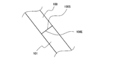
- FIG. 2 shows an explanatory view showing an enlarged example of the spiral code layer according to the present invention.
- the arrow in the figure indicates the longitudinal direction of the spiral cord layer, that is, the tire circumferential direction.
- the winding ends 100S and 100E of the reinforcing cord 100 are spirals measured along the tire surface in the tire width direction on both sides with the tire equator CL as the center. It exists within a range of 1/4 of the width SW of the cord layer 1, that is, within a range of 1/2 SW centering on the tire equator CL.
- FIG. 3 the width direction position and the magnitude of the tension acting in the spiral cord layer (using the aramid cord as the reinforcement cord) including the core cord layer between the upper layer and the lower layer as shown in FIGS.
- the graph which shows the relationship with is shown.
- the horizontal axis of the graph indicates the width direction position in the spiral cord layer having a width of 200 mm with reference to the center portion in the width direction of the spiral cord layer corresponding to the tire equator CL.
- the tension acting on the spiral cord layer which is an index of strain energy, is significantly reduced within the range of 50% on one side at the widthwise position centered on the tire equator CL, and in particular, 25 on one side. It can be seen that it is the smallest within the range of %.
- the repetitive strain during traveling that is applied to the winding ends 100S and 100E of the reinforcing cord 100 is minimized. This can be suppressed to the maximum, and as a result, the occurrence of separation starting from these winding ends 100S and 100E can be suppressed.
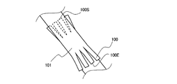
- the reinforcing cord 100 is usually spirally wound as a strip 101 formed by covering a bundle of one or two or more aligned with rubber with a predetermined inclination angle without a gap.
- the code layer 1 is formed. Therefore, for example, when the winding end 100E of the reinforcing cord 100 exists within the range of 1/2 SW centering on the tire equator CL, as shown in the drawing, the width direction center M of the winding end 100E of the reinforcing cord 100 is the tire equator. It means that it exists in the range of 1/2 SW around CL.
- both the winding end 100S at the winding start and the winding end 100E at the winding end need to exist within the range of 1/2 SW centering on the tire equator CL.
- the winding ends 100S and 100E of the reinforcing cord 100 are located on both sides with the tire equator CL as a center and within a range of 1/8 of the width SW of the spiral cord layer 1 measured along the tire surface in the tire width direction. It shall exist.
- the winding ends 100S and 100E of the reinforcing cord 100 are arranged so as to overlap each other so as to have an overlapping portion, but in the present invention, the joint portion of the winding ends 100S and 100E has such a structure.
- the form is not limited. 4 to 6 are explanatory views showing other configurations of the joint portions of the winding ends 100S and 100E.
- the winding ends 100S and 100E are arranged so as to abut each other without a gap so as not to have an overlapping portion.
- FIG. 5 shows a case where the strip 101 is composed of four reinforcing cords 100, and the positions of the cord ends of the four reinforcing cords 100 at the winding ends 100S and 100E are alternately changed along the cord longitudinal direction.
- the winding ends 100S and 100E are arranged so as to abut each other without a gap so as not to have an overlapping portion. This is because by making the positions of the cord ends of the adjacent reinforcing cords 100 different from each other along the cord longitudinal direction, the separation starting points can be separated from each other, and separation can be made less likely to occur.
- FIG. 6 also shows a case where the strip 101 is composed of four reinforcing cords 100, and the winding ends 100S and 100E of the reinforcing cords 100 are arranged so as to overlap each other in the figure. 2 is the same as that of 2, but by further making a cut in the rubber between the four reinforcing cords 100 at each of the winding ends 100S and 100E, the cord end positions of the four reinforcing cords 100 are made different in the cord width direction. There is. Also in this case, as in the case of FIG. 5, it is possible to separate the starting points of the separations to make it difficult for the separations to occur. In the present invention, as shown in FIGS.
- the reinforcing cord of the spiral cord layer has the above-mentioned predetermined inclination angle, and the winding end of the reinforcing cord is present in the above-mentioned predetermined range.
- the effect of can be obtained.
- Other configurations are not particularly limited and can be appropriately configured according to a conventional method.
- the spiral cord layer 1 is formed by spirally winding a rubber-cord composite in which one or a plurality of reinforcing cords, for example, 2 to 100, are aligned in parallel and covered with rubber. It is formed by rotating the core material cord layer 2 around the core material cord layer 2 in a spiral shape by rotating the core material cord layer 2.
- the number of reinforcing cords to be driven in the spiral cord layer 1 is preferably, for example, in the range of 5 to 60 cords/50 mm.
- the spiral cord layer 1 includes a core cord layer 2 between an upper layer 1A and a lower layer 1B, that is, a reinforcing cord is spirally wound around the core cord layer 2 to form a spiral cord.
- the core material cord layer 2 may not be provided.
- the core material cord layer 2 may be provided as a single layer or a plurality of layers, for example, 2 to 10 layers may be laminated.
- the core material cord layer 2 is manufactured by aligning a large number of core material cords in parallel, arranging unvulcanized rubbers on the upper and lower sides, and coating the core material cords with rubber.
- the number of core cords to be driven in the core cord layer 2 is preferably in the range of, for example, 5 to 60 cords/50 mm.
- the core material cord of the core material cord layer 2 may have an inclination angle of 40° or more and 90° or less with respect to the tire circumferential direction.
- the tension of the core material cord decreases, and the surplus until the core material cord breaks increases.
- the core material cord is less likely to break even when an obstacle is input.
- the inclination angle of the core cord of the core cord layer 2 is more preferably 50° or more and 90° or less with respect to the tire circumferential direction.
- the inclination angle of the reinforcing cord of the spiral cord layer 1 with respect to the tire circumferential direction is smaller than the inclination angle of the core material cord of the core material cord layer 2 with respect to the tire circumferential direction.
- the material of the reinforcing cord of the spiral cord layer 1 and the material of the core material cord of the core material cord layer 2 are not particularly limited, and various conventional general-purpose metal cords and organic fiber cords can be appropriately used. .. Specifically, for example, as the metal cord, a steel filament or a steel cord formed by twisting a plurality of steel filaments can be used. In this case, various designs of the twist structure of the cord are possible, and various cross-sectional structures, twist pitches, twist directions, and distances between adjacent filaments can be used. As the cross-sectional structure, various twist structures such as single twist, layer twist, and double twist can be adopted, and a flat cross section cord can also be used.
- the steel filament forming the steel cord contains iron as a main component and may contain various trace components such as carbon, manganese, silicon, phosphorus, sulfur, copper and chromium. Further, the surface of the steel filament may be plated with brass in order to improve the adhesiveness with rubber.
- aramid fiber aromatic polyamide fiber
- polyketone (PK) fiber polyparaphenylene benzobisoxazole (PBO) fiber
- polyarylate fiber or the like can be used.
- polyacrylonitrile (PAN)-based carbon fibers pitch-based carbon fibers, carbon fibers such as rayon-based carbon fibers (carbon fibers), glass fibers (glass fibers), rock fibers such as basalt fibers and andesite fibers (rock wool), etc.
- PAN polyacrylonitrile
- pitch-based carbon fibers carbon fibers such as rayon-based carbon fibers (carbon fibers), glass fibers (glass fibers), rock fibers such as basalt fibers and andesite fibers (rock wool), etc.
- PAN polyacrylonitrile
- pitch-based carbon fibers carbon fibers such as rayon-based carbon fibers (carbon fibers), glass fibers (glass fibers), rock fibers such as basalt fibers and andesite fibers (rock wool), etc.
- PAN polyacrylonitrile
- carbon fibers
- the rubber composition used for the coating rubber of the spiral cord layer 1 or the core cord layer 2 known rubber compositions can be used without any particular limitation.
- the rubber component of the rubber composition used for the coating rubber other than natural rubber; vinyl aromatic hydrocarbon/conjugated diene copolymer, polyisoprene rubber, butadiene rubber, butyl rubber, halogenated butyl rubber, ethylene-propylene rubber All known rubber components such as synthetic rubbers such as can be used.
- the rubber component may be used alone or in combination of two or more. From the viewpoint of the adhesive property with the metal cord and the breaking property of the rubber composition, the rubber component is composed of at least one of natural rubber and polyisoprene rubber, or contains 50% by mass or more of natural rubber and the balance is synthetic rubber. Is preferred.
- the rubber composition used for the coating rubber includes a filler such as carbon black and silica, a softening agent such as aroma oil, hexamethylenetetramine, pentamethoxymethylmelamine, methoxymethylated melamine such as hexamethylenemethylmelamine.
- a filler such as carbon black and silica
- a softening agent such as aroma oil, hexamethylenetetramine, pentamethoxymethylmelamine, methoxymethylated melamine such as hexamethylenemethylmelamine.
- Compounding agents usually used in the rubber industry such as methylene donors, vulcanization accelerators, vulcanization accelerating aids, antioxidants, etc. can be appropriately blended in the usual blending amounts.
- the rubber component is mixed with sulfur, an organic acid cobalt salt and various compounds. It may be prepared by kneading the agent and the like.
- the auxiliary belt layer 17 is arranged on the outer side of the spiral cord layer 1 in the tire radial direction.
- the auxiliary belt layer 17 can be provided as desired.
- the auxiliary belt layer 17 can be an inclined belt in which the belt cords form a predetermined angle with the tire circumferential direction, and is formed by aligning a large number of belt cords and coating them with rubber.
- the angle of the belt cord of the auxiliary belt layer 17 with respect to the tire circumferential direction is preferably in the range of 0° to 45°, more preferably 0° to 20°.
- the belt cord of the auxiliary belt layer 17 and the reinforcing cord of the upper layer 1A of the adjacent spiral cord layer 1 may be inclined in the same direction with reference to the tire circumferential direction, or may be inclined in the opposite direction. Good.
- the reinforcing cord of the auxiliary belt layer for example, a metal cord, particularly a steel cord is most commonly used, but an organic fiber cord may be used.
- the steel cord may be composed of a steel filament containing iron as a main component and various trace contents such as carbon, manganese, silicon, phosphorus, sulfur, copper and chromium.
- a steel monofilament cord may be used in addition to a cord formed by twisting a plurality of filaments.
- Various twisted structures of the steel cords can be designed, and various cross-sectional structures, twist pitches, twisting directions, and distances between adjacent steel cords can be used.
- a cord formed by twisting filaments of different materials can be adopted, and the cross-sectional structure is not particularly limited, and various twist structures such as single twist, layer twist, and double twist can be adopted.
- the width of the auxiliary belt layer 17 is preferably 40% to 115% of the tread width, and particularly preferably 50% to 70%.
- a belt under cushion rubber 18 is preferably provided on the inner side in the tire radial direction at the end of the spiral cord layer 1. As a result, the strain/temperature at the end of the spiral cord layer 1 can be reduced and the tire durability can be improved.
- the carcass 14 can adopt various configurations including a conventional structure, and may have either a radial structure or a bias structure.
- the carcass 14 it is preferable that the carcass ply made of a steel cord layer has one or two layers. Further, for example, the carcass maximum width position in the tire radial direction may be close to the bead portion 13 side or the tread portion 11 side.
- the maximum width position of the carcass 14 can be provided outside the bead base portion in the tire radial direction in a range of 50% to 90% with respect to the tire height.
- the carcass 14 is generally and preferably has a structure that extends between the pair of bead cores 15 without interruption. However, the carcass 14 is formed by using a pair of carcass pieces that extend from the bead core 15 and are interrupted near the tread portion 11. You can also
- the folded portion of the carcass 14 can adopt various structures.
- the folded end of the carcass 14 can be located on the inner side in the tire radial direction from the upper end of the bead filler 16, and the folded end of the carcass can be extended to the outer side in the tire radial direction from the upper end of the bead filler 16 or the tire maximum width position.
- the spiral cord layer 1 can be extended to the inner side in the tire width direction from the tire width direction end.
- the carcass ply has a plurality of layers, it is possible to change the position of the folded end of the carcass 14 in the tire radial direction.
- the carcass 14 may have a structure in which the carcass 14 is sandwiched between a plurality of bead core members without having the folded portion, and a structure wound around the bead core 15 may be adopted.
- the number of driving the carcass 14 is generally in the range of 5 to 60/50 mm, but is not limited to this.
- a circumferential cord layer (not shown) may be provided outside the spiral cord layer 1 and the auxiliary belt layer 17 in the tire radial direction.
- the truck/bus tire 10 of the present invention a known structure can be adopted for the sidewall portion 12 as well.
- the maximum tire width position can be provided outside the bead base portion in the tire radial direction in the range of 50% to 90% with respect to the tire height.
- the truck/bus tire 10 of the present invention is preferably formed as a smooth curve that is convex in the tire width direction without forming a recess that contacts the rim flange.
- the bead core 15 can adopt various structures such as a circular shape and a polygonal shape.
- the bead portion 13 may have a structure in which the carcass 14 is wound around the bead core 15 or a structure in which the carcass 14 is sandwiched by a plurality of bead core members.
- a bead filler 16 is arranged outside the bead core 15 in the tire radial direction.
- the bead filler 16 is composed of a plurality of rubber members divided in the tire radial direction. Good.
- the tread pattern may be a rib-shaped land-based pattern, a block pattern, an asymmetric pattern, or a rotational direction may be designated.
- the rib-like land portion main pattern is a pattern mainly including the rib-like land portion, which is divided in the tire width direction by one or more circumferential grooves or circumferential grooves and tread ends.
- the rib-shaped land portion refers to a land portion that extends in the tire circumferential direction without a lateral groove that traverses the tire width direction, but the rib-shaped land portion has a lateral groove that terminates in the sipe or the rib-shaped land portion. May be. It is considered that the radial tire has a high ground contact pressure especially under the use of a high internal pressure. Therefore, it is considered that the ground contact property on the wet road surface is improved by increasing the circumferential shear rigidity.
- a tread pattern composed only of rib-shaped land portions in a region of 80% of the tread width centered on the equatorial plane, that is, a pattern having no lateral groove may be used. it can. In such a pattern, drainage performance in this region contributes particularly to wet performance.
- the block pattern is a pattern that has a block land portion divided by a circumferential groove and a widthwise groove, and the tire of the block pattern has excellent basic on-ice performance and on-snow performance.
- the asymmetric pattern is a pattern in which the left and right tread patterns are asymmetric with respect to the equatorial plane.
- a negative ratio may be provided in the tire half portion on the vehicle mounting direction inner side and the vehicle mounting direction outer side with the equatorial plane as a boundary.
- the number of circumferential grooves may be different between the tire half on the inside in the mounting direction and the tire half on the outside in the vehicle mounting direction.
- the tread rubber is not particularly limited, and conventionally used rubber can be used. Further, the tread rubber may be formed of a plurality of rubber layers different in the tire radial direction, and may have a so-called cap/base structure, for example. As the plurality of rubber layers, those having different loss tangent, modulus, hardness, glass transition temperature, material, etc. can be used. Further, the ratio of the thickness of the plurality of rubber layers in the tire radial direction may be changed in the tire width direction, and only the circumferential groove bottom and the like may be different rubber layers from the periphery thereof.
- the tread rubber may be formed of a plurality of rubber layers different in the tire width direction, and may have a so-called split tread structure.
- the plurality of rubber layers those having different loss tangents, modulus, hardness, glass transition temperature, materials and the like can be used.
- the ratio of the length in the tire width direction of the plurality of rubber layers may be changed in the tire radial direction, and only in the vicinity of the circumferential groove, only near the tread end, only the shoulder land portion, only the center land portion, etc. Only a limited part of the area may be a rubber layer different from the surrounding area.
- the tread portion has a corner portion 11a formed at an end portion in the tire width direction.
- the tire shown in FIG. 1 is a tire for trucks and buses, but the present invention is not limited to this, and can be suitably applied to tires for passenger cars, construction vehicles, two-wheeled vehicles, aircraft, agriculture, and the like. it can. Further, the tire is not limited to a pneumatic tire, but can be applied to a solid tire or a non-pneumatic tire.
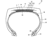
- FIG. 7 is a cross-sectional view in the tire width direction showing a configuration example of the passenger car tire of the present invention.
- the illustrated passenger car tire 20 includes a tread portion 21 that forms a ground contact portion, a pair of sidewall portions 22 that continuously extend inward in the tire radial direction on both sides of the tread portion 21, and a pair of sidewall portions 22. And a bead portion 23 continuous to the inner peripheral side.
- the tread portion 21, the sidewall portion 22, and the bead portion 23 are reinforced by a carcass 24 made of a single carcass ply extending from one bead portion 23 to the other bead portion 23 in a toroidal shape.
- bead cores 25 are embedded in the pair of bead portions 23, and the carcass 24 is folded around the bead cores 25 from the inside of the tire to the outside and locked. Further, a bead filler 26 is arranged outside the bead core 25 in the tire radial direction. ..
- a spiral cord layer 1 having a structure in which a reinforcing cord is spirally wound to form an upper layer 1A and a lower layer 1B on the tire radial direction outer side of the carcass 24,
- a core material cord layer 2 located between the upper layer 1A and the lower layer 1B and two auxiliary belt layers 27a and 27b are sequentially arranged.
- the reinforcing cord of the spiral cord layer has the predetermined inclination angle, and the winding end of the reinforcing cord is in the predetermined range. The intended effect of the present invention can be obtained.
- the carcass 24 can adopt various configurations including a conventional structure, and may have either a radial structure or a bias structure.
- the carcass ply composed of an organic fiber cord layer has one or two layers.
- the maximum width position of the carcass 24 in the tire radial direction may be close to the bead portion 23 side or the tread portion 21 side, for example.
- the maximum width position of the carcass 24 can be provided outside the bead base portion in the tire radial direction in a range of 50% to 90% with respect to the tire height.
- the carcass 24 generally has a structure in which it is possible to extend between the pair of bead cores 25 without interruption.
- the carcass 24 is formed by using a pair of carcass ply pieces that extend from the bead core 25 and are interrupted near the tread portion 21. It is also possible (not shown).
- the folded portion of the carcass 24 can adopt various structures.
- the folded end of the carcass 24 can be located inside the upper end of the bead filler 26 in the tire radial direction, and the folded end of the carcass 24 is outside the upper end of the bead filler 26 and the tire maximum width position in the tire radial direction.
- the spiral cord layer 1 can also be extended to the inner side in the tire width direction with respect to the tire width direction end.
- the position of the carcass 24 at the turning end can be different in the tire radial direction.
- the carcass 24 may have a structure in which the carcass 24 is sandwiched by a plurality of bead core members without having the folded-back portion, and a structure wound around the bead core 25 may be adopted.
- the number of driving the carcass 24 is generally in the range of 5 to 60/50 mm, but is not limited to this.
- the cap layer 27a arranged over the entire width of the spiral cord layer 1 or the layer arranged in a region covering both ends of the spiral cord layer 1.
- a layer 27b can be provided.
- the cap layer 27a and the layer layer 27b are usually formed by spirally winding a strip with a constant width formed by aligning a large number of cords and coating them with rubber in the tire circumferential direction.
- the cap layer 27a and the layer layer 27b may be provided alone or in combination. Alternatively, it may be a combination of two or more cap layers or two or more layer layers.
- the reinforcing cords of the cap layer 27a and the layer layer 27b Various materials can be used for the reinforcing cords of the cap layer 27a and the layer layer 27b. Typical examples are rayon, nylon, polyethylene naphthalate (PEN), polyethylene terephthalate (PET), aramid, glass fiber. , Carbon fiber, steel and the like. From the viewpoint of weight reduction, organic fiber cords are particularly preferable.
- the reinforcing cord a monofilament cord, a cord formed by twisting a plurality of filaments, or a hybrid cord formed by twisting filaments made of different materials can be used.
- a corrugated cord may be used as the reinforcing cord in order to increase the breaking strength.
- a high elongation cord having an elongation at break of 4.5 to 5.5% may be used.
- the cap layer 27a and the layer layer 27b are generally driven in the range of 20 to 60 lines/50 mm, but are not limited to this range. Further, in the cap layer 27a, distribution of rigidity, material, number of layers, driving density, and the like can be provided in the tire width direction, and for example, the number of layers can be increased only in the tire width direction end portion, while the center portion can be increased. Only the number of layers can be increased.
- the cap layer 27a and the layer layer 27b are configured as spiral layers.
- a plurality of core wires arranged in parallel to each other in a plane may be formed by a strip-shaped cord that is bundled by a wrapping wire while maintaining the parallel arrangement.
- the shape of the tread portion 21 in the case of a passenger car tire having a small width and a large diameter, a point P on the tread surface at the tire equatorial plane CL in the tire width direction cross section.
- the straight line parallel to the through tire width direction is m1
- the straight line passing through the ground contact edge E and parallel to the tire width direction is m2
- the distance in the tire radial direction between the straight line m1 and the straight line m2 is set to be the high LCR, and the tread width of the tire.
- Is TW, the ratio LCR/TW is preferably 0.045 or less.
- the crown portion of the tire is flattened (flattened), the ground contact area is increased, the input (pressure) from the road surface is relaxed, and the tire radial deflection The rate can be reduced, and the durability and wear resistance of the tire can be improved. Further, it is preferable that the tread end portion is smooth.
- the tread pattern may be a full lug pattern, a rib-shaped land-based pattern, a block pattern, an asymmetric pattern, or a rotation direction may be designated.
- the full lug pattern may be a pattern having a widthwise groove extending in the tire width direction from the vicinity of the equatorial plane to the ground contact end, and in this case, the circumferential groove may not be included.
- Such a pattern mainly composed of lateral grooves can effectively exhibit the performance on snow.
- the rib-shaped land main pattern is a pattern mainly composed of a rib-shaped land portion, which is divided in the tire width direction by one or more circumferential grooves or circumferential grooves and tread ends.
- the rib-shaped land portion refers to a land portion that extends in the tire circumferential direction without a lateral groove that traverses the tire width direction, but the rib-shaped land portion has a lateral groove that terminates in the sipe or the rib-shaped land portion. May be.
- the radial tire has a high ground contact pressure especially under the use of a high internal pressure. Therefore, it is considered that the ground contact property on the wet road surface is improved by increasing the circumferential shear rigidity.
- a tread pattern composed only of rib-shaped land portions in a region of 80% of the tread width centered on the equatorial plane, that is, a pattern having no lateral groove may be used. it can. In such a pattern, drainage performance in this region contributes particularly to wet performance.
- the block pattern is a pattern that has a block land portion divided by a circumferential groove and a widthwise groove, and the tire of the block pattern has excellent basic on-ice performance and on-snow performance.
- the asymmetric pattern is a pattern in which the left and right tread patterns are asymmetric with respect to the equatorial plane.
- a negative ratio may be provided in the tire half portion on the vehicle mounting direction inner side and the vehicle mounting direction outer side with the equatorial plane as a boundary.
- the number of circumferential grooves may be different between the tire half on the inside in the mounting direction and the tire half on the outside in the vehicle mounting direction.
- the tread rubber is not particularly limited, and conventionally used rubber can be used, or foamed rubber may be used. Further, the tread rubber may be formed of a plurality of rubber layers different in the tire radial direction, and may have a so-called cap/base structure, for example. As the plurality of rubber layers, those having different loss tangent, modulus, hardness, glass transition temperature, material, etc. can be used. Further, the ratio of the thickness of the plurality of rubber layers in the tire radial direction may be changed in the tire width direction, and only the circumferential groove bottom or the like may be a rubber layer different from the periphery thereof.
- the tread rubber may be formed of a plurality of rubber layers different in the tire width direction, and may have a so-called split tread structure.
- the plurality of rubber layers those having different loss tangents, modulus, hardness, glass transition temperature, materials and the like can be used.
- the ratio of the length in the tire width direction of the plurality of rubber layers may be changed in the tire radial direction, and only in the vicinity of the circumferential groove, only near the tread end, only the shoulder land portion, only the center land portion, etc. Only a limited part of the area may be a rubber layer different from the surrounding area.
- the sidewall portion 22 In the passenger car tire 20 of the present invention, a known structure can be adopted for the sidewall portion 22.
- the maximum tire width position can be provided outside the bead base portion in the tire radial direction in the range of 50% to 90% with respect to the tire height. Further, it may have a structure having a rim guard.
- the recess 23a that contacts the rim flange it is preferable that the recess 23a that contacts the rim flange be formed.
- the bead core 25 can adopt various structures such as a circular shape and a polygonal shape.
- the bead portion 23 may have a structure in which the carcass 24 is wound around the bead core 25 or a structure in which the carcass 24 is sandwiched by a plurality of bead core members.
- the bead filler 26 is arranged on the outer side in the tire radial direction of the bead core 25.
- the bead filler 26 may not be provided.
- the passenger car tire of the present invention may usually have an inner liner disposed in the innermost layer of the tire.
- the inner liner can be formed of a rubber layer containing butyl rubber as a main component and a film layer containing resin as a main component.
- a porous member may be arranged on the inner surface of the tire to reduce cavity resonance noise, or electrostatic flocking may be performed.
- the inner surface of the tire may be provided with a sealant member for preventing air leakage during puncture.
- the use of the passenger car tire 20 is not particularly limited. It can be applied to tires for summer, all season, winter, etc. Further, it can be used for a side-reinforcement type run flat tire having a crescent-shaped reinforcing rubber layer in the side wall portion 22 and a passenger car tire having a special structure such as a stud tire.
- FIG. 8 is a tire width direction cross-sectional view showing a configuration example of the construction vehicle tire of the present invention.
- a tread portion 31 forming a ground contact portion, a pair of sidewall portions 32 continuously extending inward in the tire radial direction on both sides of the tread portion 31, and each sidewall portion.
- a bead portion 33 continuous to the inner peripheral side of 32.
- the tread portion 31, the sidewall portion 32, and the bead portion 33 are reinforced by a carcass 34 made of a single carcass ply extending in a toroidal shape from one bead portion 33 to the other bead portion 33.
- a bead core 35 is embedded in each of the pair of bead portions 33, and the carcass 34 is folded around the bead core 35 from the inside of the tire to the outside and locked. Further, a bead filler 36 is arranged on the outer side of the bead core 35 in the tire radial direction.
- a spiral cord layer 1 having a structure in which an upper layer 1A and a lower layer 1B are formed by spirally winding a reinforcing cord on the tire radial direction outer side of a crown region of a carcass 34.
- the core material cord layer 2 located between the upper layer 1A and the lower layer 1B, and the four belt layers 37a to 37d are sequentially arranged.
- the reinforcing cord of the spiral cord layer has the above-mentioned predetermined inclination angle and the winding end of the reinforcing cord is within the above-mentioned predetermined range. Therefore, the intended effect of the present invention can be obtained.
- the four belt layers 37 correspond to the auxiliary belt layers.
- a tire for a construction vehicle is composed of four or six belt layers.
- the first belt layer and the second belt layer form an inner interlaced belt layer group and the third belt layer.
- the layer and the fourth belt layer form an intermediate intersecting belt layer group
- the fifth belt layer and the sixth belt layer form an outer intersecting belt layer group.
- the inner intersecting belt layer group is replaced with the spiral cord layer 1
- the auxiliary belt layers 37a to 37d are arranged as the intermediate intersecting belt layer group and the outer intersecting belt layer group.
- the first belt layer and the second belt layer are replaced with the spiral cord layer 1
- the third belt layer and the fourth belt layer are replaced with the auxiliary belt layers 37a, It may be 37b.
- the width of the spiral cord layer 1 is 25% or more and 70% or less of the width of the tread tread
- the width of the auxiliary belt layers 37a and 37b is the width of the tread tread. 55% or more and 90% or less
- the width of the auxiliary belt layers 37c and 37d can be 60% or more and 110% or less of the width of the tread tread surface.
- the inclination angle of the belt cords of the auxiliary belt layers 37a and 37b with respect to the carcass cord is 50° or more and 75° or less
- the inclination angle of the belt cords of the auxiliary belt layers 37c and 37d with respect to the carcass cord is 70°. The angle can be set to 85° or less.
- the auxiliary belt layer 37 is made of a rubberized layer of a reinforcing cord, and can be an inclined belt forming a predetermined angle with respect to the tire circumferential direction.
- a reinforcing cord of the inclined belt layer for example, a metal cord, particularly a steel cord is most commonly used, but an organic fiber cord may be used.
- the steel cord may be composed of a steel filament containing iron as a main component and various trace contents such as carbon, manganese, silicon, phosphorus, sulfur, copper and chromium.
- a steel monofilament cord may be used in addition to a cord formed by twisting a plurality of filaments.
- Various twisted structures of the steel cords can be designed, and various cross-sectional structures, twist pitches, twisting directions, and distances between adjacent steel cords can be used.
- a cord formed by twisting filaments of different materials can be adopted, and the cross-sectional structure is not particularly limited, and various twist structures such as single twist, layer twist, and double twist can be adopted.
- the inclination angle of the reinforcing cords of the other belt layers is preferably 10° or more with respect to the tire circumferential direction.
- the width of the maximum width inclined belt layer having the largest width among the auxiliary belt layers 37 is preferably 90% to 115% of the tread width, and particularly preferably 100% to 105%.
- a belt under cushion rubber 38 is preferably provided on the inner side in the tire radial direction of the end portion of the auxiliary belt layer 37.
- the carcass 34 can adopt various configurations including a conventional structure, and may have either a radial structure or a bias structure.
- the carcass 34 it is preferable that the carcass ply made of a steel cord layer has one or two layers. Further, for example, the carcass maximum width position in the tire radial direction may be close to the bead portion 33 side or the tread portion 31 side.
- the maximum width position of the carcass 34 can be provided outside the bead base portion in the tire radial direction in a range of 50% to 90% with respect to the tire height.
- the carcass 34 is generally and preferably has a structure that extends between the pair of bead cores 35 without interruption, but is formed using a pair of carcass pieces that extend from the bead core 35 and are interrupted near the tread portion 31. You can also
- the folded portion of the carcass 34 can adopt various structures.
- the folded end of the carcass 34 can be located on the inner side in the tire radial direction with respect to the upper end of the bead filler 36, and the folded end of the carcass 34 is on the outer side in the tire radial direction from the upper end of the bead filler 36 and the tire maximum width position.
- the spiral cord layer 1 can also be extended to the inner side in the tire width direction with respect to the tire width direction end.
- the position of the folded end of the carcass 34 in the tire radial direction can be different.
- the carcass 34 may have a structure in which the carcass 34 is sandwiched by a plurality of bead core members without having the folded portion, and a structure wound around the bead core 35 may be employed.
- the number of driving the carcass 34 is generally in the range of 5 to 60 pieces/50 mm, but is not limited to this.
- the maximum tire width position can be provided outside the bead base portion in the tire radial direction in the range of 50% to 90% with respect to the tire height.
- the bead core 35 can adopt various structures such as a circular shape and a polygonal shape.
- the bead portion 33 may have a structure in which the carcass 34 is wound around the bead core 35 or a structure in which the carcass 34 is sandwiched by a plurality of bead core members.
- the bead filler 36 is arranged outside the bead core 35 in the tire radial direction.
- the bead filler 36 may be composed of a plurality of rubber members divided in the tire radial direction. Good.
- the tread pattern may be a lug pattern, a block pattern, an asymmetric pattern, or may be a rotation direction designation.
- the lug pattern may have a width direction groove extending in the tire width direction from the vicinity of the equatorial plane to the ground contact end, and in this case, the circumferential groove may not be included.
- the block pattern is a pattern that has a block land portion divided by a circumferential groove and a widthwise groove. Particularly in the case of tires for construction vehicles, it is preferable to make the block large from the viewpoint of durability, and for example, the width of the block measured in the tire width direction is preferably 25% or more and 50% or less of the tread width.
- the asymmetric pattern is a pattern in which the left and right tread patterns are asymmetric with respect to the equatorial plane.
- a negative ratio may be provided in the tire half portion on the vehicle mounting direction inner side and the vehicle mounting direction outer side with the equatorial plane as a boundary.
- the number of circumferential grooves may be different between the tire half on the inside in the mounting direction and the tire half on the outside in the vehicle mounting direction.
- the tread rubber is not particularly limited, and conventionally used rubber can be used. Further, the tread rubber may be formed of a plurality of rubber layers different in the tire radial direction, and may have a so-called cap/base structure, for example. As the plurality of rubber layers, those having different loss tangent, modulus, hardness, glass transition temperature, material, etc. can be used. Further, the ratio of the thickness of the plurality of rubber layers in the tire radial direction may be changed in the tire width direction, and only the circumferential groove bottom or the like may be a rubber layer different from the periphery thereof.
- the tread rubber may be formed of a plurality of rubber layers different in the tire width direction, and may have a so-called split tread structure.
- the plurality of rubber layers those having different loss tangents, modulus, hardness, glass transition temperature, materials and the like can be used.
- the ratio of the length in the tire width direction of the plurality of rubber layers may be changed in the tire radial direction, and only in the vicinity of the circumferential groove, only near the tread end, only the shoulder land portion, only the center land portion, etc. Only a limited part of the area may be a rubber layer different from the surrounding area.
- the rubber gauge of the tread portion 31 is preferably thick from the viewpoint of durability, and is preferably 1.5% or more and 4% or less of the tire outer diameter, and more preferably 2% or more and 3% or less. ..
- the ratio of the groove area to the ground contact surface of the tread portion 31 (negative ratio) is preferably 20% or less. This is because the construction vehicle tire 30 is mainly used at low speed and in a dry area, and therefore it is not necessary to increase the negative rate because of drainage.
- the tire size of the construction vehicle tire is, for example, a rim diameter of 20 inches or more, and particularly a large tire has a rim diameter of 40 inches or more.
- auxiliary belt layer is arranged on the outer side in the tire radial direction.
- Core material cord of core material cord layer and belt cord of auxiliary belt layer A steel cord with a 1+6 structure that uses a steel filament with a wire diameter of 1.13 mm.
- Inclination angle of steel cord of core cord layer 50° to the longitudinal direction of the reinforcing member.
- Inclination angle of steel cord of auxiliary belt layer 16° to the longitudinal direction of the reinforcing member.
- tilt direction of steel cord of auxiliary belt layer In the same direction as the reinforcing cord in the upper layer of the adjacent spiral cord layer.
- the “applicable rim” refers to a rim defined by the following standards according to the size of the tire.
- the “specified internal pressure” means an air pressure specified in accordance with the maximum load capacity in the following standards.
- the standard refers to an industrial standard that is effective in regions where tires are produced or used. For example, in the United States, “THE TIRE AND RIM ASSOCIATION INC. YEAR BOOK”, and in Europe, “THE EUROPEAN TYRE AND AND RIM Technical Organization's STANDARDS MANUAL”, and in Japan, the Japan Automobile Tire Manufacturers Association's “JATMA YEAR BOOK”.
Landscapes
- Engineering & Computer Science (AREA)
- Mechanical Engineering (AREA)
- Tires In General (AREA)
Abstract
螺旋状コード層の補強コードの巻き付け端からのセパレーションの発生を抑制して、耐久性を向上したタイヤを提供する。 一対のビード部間にトロイド状に延在するカーカスと、カーカスのクラウン部タイヤ半径方向外側に配置され、補強コードを螺旋状に巻回して上層と下層とを形成した螺旋状コード層と、を備えるタイヤである。螺旋状コード層1の補強コード100のタイヤ周方向に対する傾斜角度が10°以上45°以下であって、かつ、補強コードの巻き付け端100S,100Eが、タイヤ赤道を中心として両側に、タイヤ幅方向にタイヤ表面に沿って測った螺旋状コード層の幅SWの1/4の範囲内に存在する。
Description
本発明はタイヤに関し、詳しくは、クラウン部に、補強コードを螺旋状に巻回して上層と下層とを形成した螺旋状コード層を備えるタイヤの改良に関する。
従来より、タイヤの補強部材に関しては、種々検討がなされてきている。例えば、乗用車用タイヤの補強部材であるベルトの構造としては、タイヤの骨格部材となるカーカスのクラウン部タイヤ半径方向外側に、補強コードのコード方向が互いに交錯する2層以上のベルト交錯層を配設した構造が一般的である。これ以外にも、ベルトの構造として、上下2層のベルト層を補強コードを互いに交差するように配置するとともに、補強コードをベルト層端部で折り返して、一方から他方のベルト層に延在する螺旋巻き構造とする形態も知られている。
このような構造として、例えば、特許文献1には、少なくとも1層の芯材コード層と、該芯材コード層に螺旋状に巻き付けられた補強コードを有する螺旋状コード層と、を有するタイヤ用補強部材において、前記芯材コード層中の補強コードが金属コードであり、かつ、該金属コードが前記芯材コード層の長手方向に対して40~90°の傾斜角度を有し、前記螺旋状コード層中の補強コードが、19GPa以上のモジュラスを有する有機繊維コードであるタイヤ用補強部材およびこれを用いたタイヤが開示されている。
特許文献1に開示されているような螺旋状コード層においては、通常の切り離しベルトなどとは異なり幅方向端部に補強コードの切断端が存在しないため、幅方向端部からのセパレーションの発生を防止することができる。その一方、走行中に、螺旋状コード層に対し張力がかかって、歪が繰り返し生ずることにより、螺旋状コード層の補強コードの巻き付け端からセパレーションが発生するという新たな問題が生ずるおそれがあった。巻き付け端から発生したセパレーションが螺旋状コード層の幅方向端部まで達すると、このセパレーションが幅方向端部に沿って周方向に進展して、耐久性を悪化させるため、補強コードの巻き付け端からのセパレーションの発生を抑制することが求められる。
そこで本発明の目的は、上記問題を解消して、螺旋状コード層の補強コードの巻き付け端からのセパレーションの発生を抑制して、耐久性を向上したタイヤを提供することにある。
本発明者は鋭意検討した結果、特に上記セパレーション発生の問題が生じやすいコード角度条件において、補強コードの巻き付け端の位置を所定に規定することにより、上記問題を解消できることを見出して、本発明を完成するに至った。
すなわち、本発明は、一対のビード部間にトロイド状に延在するカーカスと、該カーカスのクラウン部タイヤ半径方向外側に配置され、補強コードを螺旋状に巻回して上層と下層とを形成した螺旋状コード層と、を備えるタイヤであって、
前記螺旋状コード層の補強コードのタイヤ周方向に対する傾斜角度が10°以上45°以下であって、かつ、該補強コードの巻き付け端が、タイヤ赤道を中心として両側に、タイヤ幅方向にタイヤ表面に沿って測った螺旋状コード層の幅SWの1/4の範囲内に存在することを特徴とするものである。
前記螺旋状コード層の補強コードのタイヤ周方向に対する傾斜角度が10°以上45°以下であって、かつ、該補強コードの巻き付け端が、タイヤ赤道を中心として両側に、タイヤ幅方向にタイヤ表面に沿って測った螺旋状コード層の幅SWの1/4の範囲内に存在することを特徴とするものである。
本発明のタイヤは、前記螺旋状コード層の上層と下層との間に、芯材コード層を備えるものとすることもできる。
本発明によれば、螺旋状コード層の補強コードの巻き付け端からのセパレーションの発生を抑制したタイヤを実現することができた。
以下、本発明について、図面を用いて詳細に説明する。
図1は、本発明のタイヤの一例のトラック・バス用タイヤを示すタイヤ幅方向断面図である。図示するタイヤ10は、接地部を形成するトレッド部11と、このトレッド部11の両側部に連続してタイヤ半径方向内方へ延びる一対のサイドウォール部12と、各サイドウォール部12の内周側に連続するビード部13と、を備えている。トレッド部11、サイドウォール部12およびビード部13は、一方のビード部13から他方のビード部13にわたってトロイド状に延在する一枚のカーカスプライからなるカーカス14により補強されている。また、図示するトラック・バス用タイヤ10においては、一対のビード部13にはそれぞれビードコア15が埋設され、カーカス14は、このビードコア15の周りにタイヤ内側から外側に折り返して係止されている。さらに、ビードコア15のタイヤ半径方向外側には、ビードフィラー16が配置されている。
図1は、本発明のタイヤの一例のトラック・バス用タイヤを示すタイヤ幅方向断面図である。図示するタイヤ10は、接地部を形成するトレッド部11と、このトレッド部11の両側部に連続してタイヤ半径方向内方へ延びる一対のサイドウォール部12と、各サイドウォール部12の内周側に連続するビード部13と、を備えている。トレッド部11、サイドウォール部12およびビード部13は、一方のビード部13から他方のビード部13にわたってトロイド状に延在する一枚のカーカスプライからなるカーカス14により補強されている。また、図示するトラック・バス用タイヤ10においては、一対のビード部13にはそれぞれビードコア15が埋設され、カーカス14は、このビードコア15の周りにタイヤ内側から外側に折り返して係止されている。さらに、ビードコア15のタイヤ半径方向外側には、ビードフィラー16が配置されている。
また、本発明のタイヤは、カーカス14のクラウン部タイヤ半径方向外側に、補強コードを螺旋状に巻回して上層1Aと下層1Bとを形成してなる構造を有する螺旋状コード層1を備えている。
本発明においては、螺旋状コード層1の補強コードのタイヤ周方向に対する傾斜角度が10°以上45°以下である。螺旋状コード層1の補強コードのタイヤ周方向に対する傾斜角度が上記範囲内であって比較的タイヤ周方向に近い場合、螺旋状コード層1がタイヤの張力を負担することになるので、螺旋状コード層の補強コードの巻き付け端からのセパレーションの問題が生じやすいと考えられ、本発明の適用が有用である。なお、本発明において、螺旋状コード層1の補強コードの傾斜角度は、タイヤ赤道面上で測定した値を用いることができる。
図2に、本発明に係る螺旋状コード層の一例を拡大して示す説明図を示す。図中の矢印は、螺旋状コード層の長手方向、すなわち、タイヤ周方向を示す。図示するように、本発明においては、螺旋状コード層1において、補強コード100の巻き付け端100S,100Eが、タイヤ赤道CLを中心として両側に、タイヤ幅方向にタイヤ表面に沿って測った螺旋状コード層1の幅SWの1/4の範囲内、すなわち、タイヤ赤道CLを中心とした1/2SWの範囲内に存在する。
図3に、図1,2に示すような、上層と下層との間に芯材コード層を備える螺旋状コード層(補強コードにアラミドコードを使用)における、幅方向位置と作用する張力の大きさとの関係を示すグラフを示す。グラフの横軸は、タイヤ赤道CLに対応する螺旋状コード層の幅方向中心部を基準として、幅200mmの螺旋状コード層における幅方向位置を示したものである。このグラフから、歪エネルギーの指標となる、螺旋状コード層に作用する張力は、タイヤ赤道CLを中心とする幅方向位置で片側50%の範囲内において大幅に低下しており、特に、片側25%の範囲内において最も小さくなっていることがわかる。よって、補強コード100の巻き付け端100S,100Eをタイヤ赤道CLを中心とした1/2SWの範囲内に位置させることで、補強コード100の巻き付け端100S,100Eにかかる、走行中の繰り返し歪を最小限に抑制することができ、結果として、これら巻き付け端100S,100Eを起点とするセパレーションの発生を抑制することができる。
ここで、図示するように、通常、補強コード100は、1本または2本以上を引き揃えた束をゴムにより被覆してなるストリップ101として、所定の傾斜角度で隙間なく巻回されて螺旋状コード層1を形成する。よって、例えば、補強コード100の巻き付け端100Eがタイヤ赤道CLを中心とした1/2SWの範囲内に存在するとは、図示するように、補強コード100の巻き付け端100Eの幅方向中心Mがタイヤ赤道CLを中心とした1/2SWの範囲に存在することを意味する。また、本発明においては、補強コード100の巻き付け端のうち巻き始めの巻き付け端100Sおよび巻き終わりの巻き付け端100Eの両方がタイヤ赤道CLを中心とした1/2SWの範囲内に存在することが必要である。好ましくは、補強コード100の巻き付け端100S,100Eは、タイヤ赤道CLを中心として両側に、タイヤ幅方向にタイヤ表面に沿って測った螺旋状コード層1の幅SWの1/8の範囲内に存在するものとする。
図示する例では、補強コード100の巻き付け端100S,100Eを、重なり部分を有するようにオーバーラップして配置しているが、本発明においては、巻き付け端100S,100Eのジョイント部は、このような形態には制限されない。図4~図6に、巻き付け端100S,100Eのジョイント部の他の形態を示す説明図を示す。図4においては、巻き付け端100S,100Eを、重なり部分を有しないように互いに隙間なく突き合わせて配置している。図5は、ストリップ101が4本の補強コード100から構成されている場合であり、巻き付け端100S,100Eそれぞれにおける4本の補強コード100のコード端のコード長手方向に沿った位置を交互に変えた上で、図4と同様に、巻き付け端100S,100Eを、重なり部分を有しないように互いに隙間なく突き合わせて配置している。これは、隣り合う補強コード100のコード端のコード長手方向に沿った位置を異ならせることで、セパレーションの起点同士を離すことができ、セパレーションを発生しにくくすることができるためである。図6も、ストリップ101が4本の補強コード100から構成されている場合であり、補強コード100の巻き付け端100S,100Eを、重なり部分を有するようにオーバーラップして配置している点は図2と同様であるが、さらに、巻き付け端100S,100Eそれぞれにおける4本の補強コード100間のゴムに切り込みを入れることで、4本の補強コード100のコード端位置をコード幅方向に異ならせている。この場合も、図5の場合と同様に、セパレーションの起点同士を離して、セパレーションを発生しにくくすることができる。なお、本発明においては、図5,6に示すように、ストリップ101を構成する複数本の補強コード100の巻き付け端100S,100Eの位置がそれぞれ異なる場合、すべての補強コード100の巻き付け端100S,100Eがタイヤ赤道CLを中心とした1/2SWの範囲内に存在することが必要である。
本発明においては、螺旋状コード層の補強コードが上記所定の傾斜角度を有するとともに、補強コードの巻き付け端が、上記所定の範囲に存在する点のみが重要であり、これにより本発明の所期の効果を得ることができる。それ以外の構成については特に制限はなく、常法に従い適宜構成することが可能である。
本発明において、螺旋状コード層1は、補強コードを1本または複数本、例えば、2~100本で並列に引き揃えて、ゴムにより被覆してなるゴム-コード複合体を、螺旋状に巻回して平坦な帯状体とするか、または、芯材コード層2の周囲に螺旋状に巻き付けることにより形成される。螺旋状コード層1における補強コードの打ち込み数は、例えば、5~60本/50mmの範囲が好ましい。
図示する例では、螺旋状コード層1は、上層1Aと下層1Bとの間に芯材コード層2を備え、すなわち、芯材コード層2に対し補強コードが螺旋状に巻き付けられて螺旋状コード層1が形成されているが、本発明においては、これに制限されず、芯材コード層2は設けなくてもよい。また、芯材コード層2を設ける場合、芯材コード層2は1層で設けてもよく、複数層、例えば、2~10層で積層して設けることもできる。ここで、芯材コード層2は、芯材コードを多数本並行に引き揃え、この上下に未加硫ゴムを配置して、芯材コードをゴム被覆することにより製造される。芯材コード層2における芯材コードの打ち込み数は、例えば、5~60本/50mmの範囲が好ましい。
本発明において、芯材コード層2の芯材コードは、タイヤ周方向に対して40°以上90°以下の傾斜角度を有するものとすることができる。芯材コードの角度を上記範囲とすることで、芯材コードの張力が低下して、芯材コードの破断に至るまでの余剰が多くなる。その結果、障害物の入力を受けても芯材コードは破断しにくくなる。このような効果を良好に得るためには、芯材コード層2の芯材コードの傾斜角度は、タイヤ周方向に対し50°以上90°以下であることがより好ましい。なお、芯材コード層2を複数層設ける場合には、複数層の芯材コード層2が交錯層を構成してもよい。ここで、芯材コード層2を設ける場合には、螺旋状コード層1の補強コードのタイヤ周方向に対する傾斜角度が、芯材コード層2の芯材コードのタイヤ周方向に対する傾斜角度よりも小さいことが、本発明を適用する上で有用である。これは、芯材コード層2を設けた場合において、上記角度条件を満たすと、螺旋状コード層1が張力を負担することになるので、螺旋状コード層1の補強コードの巻き付け端からのセパレーションの問題が生じやすいためである。
本発明において、螺旋状コード層1の補強コードおよび芯材コード層2の芯材コードの材質としては、特に制限はなく、従来汎用の各種の金属コードや有機繊維コードなどを適宜用いることができる。具体的には例えば、金属コードとしては、スチールフィラメントや、スチールフィラメントを複数本撚り合わせたスチールコードを用いることができる。この場合、コードの撚り構造についても種々の設計が可能であり、断面構造、撚りピッチ、撚り方向、隣接するフィラメント同士の距離も様々なものが使用できる。断面構造としては、単撚り、層撚り、複撚りなど様々な撚り構造を採用することができ、また、断面形状が偏平のコードを使用することもできる。なお、スチールコードを構成するスチールフィラメントは、鉄を主成分とし、炭素、マンガン、ケイ素、リン、硫黄、銅、クロムなど種々の微量成分を含んでいてもよい。また、スチールフィラメントの表面には、ゴムとの接着性を改善するため、ブラスめっきが施されていてもよい。
有機繊維としては、アラミド繊維(芳香族ポリアミド繊維)、ポリケトン(PK)繊維、ポリパラフェニレンベンゾビスオキサゾール(PBO)繊維、ポリアリレート繊維等を用いることができる。また、ポリアクリロニトリル(PAN)系炭素繊維やピッチ系炭素繊維、レーヨン系炭素繊維等の炭素繊維(カーボンファイバー)、ガラス繊維(グラスファイバー)、玄武岩繊維や安山岩繊維等の岩石繊維(ロックウール)などを用いることもできる。なお、これらの補強コードには、接着剤処理を施してゴムとの接着性を向上させることが好ましい。この接着剤処理は、RFL系接着剤等の汎用の接着剤を用いて、常法に従って行うことができる。さらに、上記のうちのいずれか2種以上からなるハイブリッドコードを用いてもよい。
本発明において、螺旋状コード層1や芯材コード層2のコーティングゴムに用いるゴム組成物としては、既知のものを用いることができ、特に制限されない。例えば、コーティングゴムに用いられるゴム組成物のゴム成分としては、天然ゴムの他;ビニル芳香族炭化水素/共役ジエン共重合体、ポリイソプレンゴム、ブタジエンゴム、ブチルゴム、ハロゲン化ブチルゴム、エチレン-プロピレンゴム等の合成ゴム等の公知のゴム成分の全てを用いることができる。ゴム成分は1種単独で用いても、2種以上を併用してもよい。金属コードとの接着特性およびゴム組成物の破壊特性の観点からは、ゴム成分としては、天然ゴムおよびポリイソプレンゴムの少なくとも一方よりなるか、50質量%以上の天然ゴムを含み残部が合成ゴムからなるものが好ましい。
本発明において、コーティングゴムに用いられるゴム組成物には、カーボンブラックやシリカ等の充填剤、アロマオイル等の軟化剤、ヘキサメチレンテトラミン、ペンタメトキシメチルメラミン、ヘキサメチレンメチルメラミン等のメトキシメチル化メラミン等のメチレン供与体、加硫促進剤、加硫促進助剤、老化防止剤等のゴム業界で通常使用される配合剤を通常の配合量で適宜配合することができる。また、本発明においてコーティングゴムとして用いられるゴム組成物の調製方法に特に制限はなく、常法に従い、例えば、バンバリーミキサーやロール等を用いて、ゴム成分に、硫黄、有機酸コバルト塩および各種配合剤等を練り込んで調製すればよい。
また、図示するトラック・バス用タイヤ10においては、螺旋状コード層1のタイヤ半径方向外側に、補助ベルト層17が配置されている。本発明において、補助ベルト層17は、所望に応じ設けることができる。補助ベルト層17は、ベルトコードがタイヤ周方向に対し所定の角度をなす傾斜ベルトとすることができ、ベルトコードを多数本引き揃えて、ゴムにより被覆することによって形成される。
本発明において、補助ベルト層17のベルトコードのタイヤ周方向に対する角度は、0°以上45°以下の範囲とすることが好ましく、より好ましくは0°以上20°以下の範囲である。ベルトコードのタイヤ周方向に対する角度が45°を超えると、ベルトコードがタイヤ周方向の張力をほとんど負担しなくなるために、螺旋状コード層の補強コードの耐久性向上効果が得られなくなる。また、補助ベルト層17のベルトコードと、隣接する螺旋状コード層1の上層1Aの補強コードとは、タイヤ周方向を基準として同方向に傾斜していてもよく、逆方向に傾斜していてもよい。
補助ベルト層の補強コードとしては、例えば、金属コード、特にスチールコードを用いるのが最も一般的であるが、有機繊維コードを用いてもよい。スチールコードは鉄を主成分とし、炭素、マンガン、ケイ素、リン、硫黄、銅、クロムなど種々の微量含有物を含むスチールフィラメントからなるものを用いることができる。
スチールコードとしては、複数のフィラメントを撚り合せたコード以外にも、スチールモノフィラメントコードを用いてもよい。なお、スチールコードの撚り構造も種々の設計が可能であり、断面構造、撚りピッチ、撚り方向、隣接するスチールコード同士の距離も様々なものが使用できる。また、異なる材質のフィラメントを撚り合せたコードを採用することもでき、断面構造としても特に限定されず、単撚り、層撚り、複撚りなど様々な撚り構造を取ることができる。また、補助ベルト層17の幅は、トレッド幅の40%~115%とすることが好ましく、特に50%~70%が好ましい。なお、螺旋状コード層1の端部のタイヤ径方向内側には、ベルトアンダークッションゴム18を設けることが好ましい。これにより、螺旋状コード層1の端部の歪・温度を低減して、タイヤ耐久性を向上させることができる。
本発明のトラック・バス用タイヤ10においては、カーカス14は従来構造を含めて種々の構成を採用することができ、ラジアル構造、バイアス構造のいずれであってもよい。カーカス14としては、スチールコード層からなるカーカスプライを1~2層とすることが好ましい。また、例えば、タイヤ径方向におけるカーカス最大幅位置は、ビード部13側に近づけてもよく、トレッド部11側に近づけてもよい。例えば、カーカス14の最大幅位置は、ビードベース部からタイヤ径方向外側に、タイヤ高さ対比で50%~90%の範囲に設けることができる。また、カーカス14は、図示するように、一対のビードコア15間を途切れずに延びる構造が一般的であり好ましいが、ビードコア15から延びてトレッド部11付近で途切れるカーカス片を一対用いて形成することもできる。
また、カーカス14の折り返し部は、さまざまな構造を採用することができる。例えば、カーカス14の折り返し端をビードフィラー16の上端よりもタイヤ径方向内側に位置させることができ、また、カーカス折り返し端をビードフィラー16の上端やタイヤ最大幅位置よりもタイヤ径方向外側まで延ばしてもよく、この場合、螺旋状コード層1のタイヤ幅方向端よりもタイヤ幅方向内側まで延ばすこともできる。さらに、カーカスプライが複数層の場合には、カーカス14の折り返し端のタイヤ径方向位置を異ならせることもできる。また、カーカス14の折り返し部を存在させずに、複数のビードコア部材で挟み込んだ構造としてもよく、ビードコア15に巻きつけた構造を採用することもできる。なお、カーカス14の打ち込み数としては、一般的には5~60本/50mmの範囲であるが、これに限定されるものではない。
また、本発明のトラック・バス用タイヤ10においては、螺旋状コード層1および補助ベルト層17のタイヤ径方向外側に、周方向コード層(図示せず)を設けてもよい。
本発明のトラック・バス用タイヤ10においては、サイドウォール部12の構成についても既知の構造を採用することができる。例えば、タイヤ最大幅位置は、ビードベース部からタイヤ径方向外側に、タイヤ高さ対比で50%~90%の範囲に設けることができる。本発明のトラック・バス用タイヤ10においては、乗用車用タイヤとは異なり、リムフランジと接触する凹部が形成されずに、タイヤ幅方向に凸となる滑らかな曲線として形成されていることが好ましい。
また、ビードコア15は、円形や多角形状など、さまざまな構造を採用することができる。なお、上述のとおり、ビード部13としては、カーカス14をビードコア15に巻きつける構造のほか、カーカス14を複数のビードコア部材で挟みこむ構造としてもよい。図示するトラック・バス用タイヤ10においては、ビードコア15のタイヤ半径方向外側にビードフィラー16が配置されているが、このビードフィラー16は、タイヤ径方向に分かれた複数のゴム部材から構成されていてもよい。
本発明のトラック・バス用タイヤ10においては、トレッドパターンとしては、リブ状陸部主体のパターン、ブロックパターン、非対称パターンでもよく、回転方向指定であってもよい。
リブ状陸部主体パターンは、一本以上の周方向溝もしくは周方向溝とトレッド端部によりタイヤ幅方向を区画された、リブ状陸部を主体とするパターンである。ここでリブ状陸部とはタイヤ幅方向に横断する横溝を有さずにタイヤ周方向に延びる陸部をいうが、リブ状陸部はサイプやリブ状陸部内で終端する横溝を有していてもよい。ラジアルタイヤは特に高内圧使用下において高接地圧となるため、周方向剪断剛性を増加させることによりウェット路面上での接地性が向上するためと考えられる。リブ状陸部を主体とするパターンの例としては、赤道面を中心とするトレッド幅の80%の領域においてリブ状陸部のみからなるトレッドパターン、すなわち、横溝を有さないパターンとすることができる。このようなパターンは、この領域における排水性能が特にウェット性能への寄与が大きい。
ブロックパターンは、周方向溝と幅方向溝によって区画されたブロック陸部を有するパターンであり、ブロックパターンのタイヤは、基本的な氷上性能および雪上性能に優れている。
非対称パターンは、赤道面を境として左右のトレッドパターンが非対称のパターンである。例えば、装着方向指定のタイヤの場合には、赤道面を境とした車両装着方向内側と車両装着方向外側のタイヤ半部においてネガティブ率に差を設けたものでもよく、赤道面を境とした車両装着方向内側と車両装着方向外側のタイヤ半部において、周方向溝の数が異なる構成のものであってもよい。
トレッドゴムとしては、特に制限はなく、従来から用いられているゴムを用いることができる。また、トレッドゴムはタイヤ径方向に異なる複数のゴム層で形成されていてもよく、例えば、いわゆるキャップ・ベース構造であってもよい。複数のゴム層としては損失正接、モジュラス、硬度、ガラス転移温度、材質等が異なっているものを使用することができる。また、複数のゴム層のタイヤ径方向の厚みの比率は、タイヤ幅方向に変化していてもよく、また周方向溝底のみ等をその周辺と異なるゴム層とすることもできる。
さらに、トレッドゴムはタイヤ幅方向に異なる複数のゴム層で形成されていてもよく、いわゆる、分割トレッド構造でもよい。上記の複数のゴム層としては損失正接、モジュラス、硬度、ガラス転移温度、材質等が異なっているものを使用することができる。また、複数のゴム層のタイヤ幅方向の長さの比率は、タイヤ径方向に変化していてもよく、また周方向溝近傍のみ、トレッド端近傍のみ、ショルダー陸部のみ、センター陸部のみといった限定された一部の領域のみをその周囲とは異なるゴム層とすることもできる。また、トレッド部は、タイヤ幅方向の端部に角部11aが形成されていることが好ましい。
図1に示すタイヤはトラック・バス用タイヤであるが、本発明は、これに限られず、乗用車用、建設車両用、二輪車用、航空機用、農業用のタイヤ等にも好適に適用することができる。また、タイヤとしては、空気入りタイヤに限定されず、ソリッドタイヤや非空気入りタイヤにも適用することができる。
図7は、本発明の乗用車用タイヤの一構成例を示すタイヤ幅方向断面図である。図示する乗用車用タイヤ20は、接地部を形成するトレッド部21と、このトレッド部21の両側部に連続してタイヤ半径方向内方へ延びる一対のサイドウォール部22と、各サイドウォール部22の内周側に連続するビード部23と、を備えている。トレッド部21、サイドウォール部22およびビード部23は、一方のビード部23から他方のビード部23にわたってトロイド状に延びる一枚のカーカスプライからなるカーカス24により補強されている。また、図示する乗用車用タイヤ20においては、一対のビード部23にはそれぞれビードコア25が埋設され、カーカス24は、このビードコア25の周りにタイヤ内側から外側に折り返して係止されている。さらに、ビードコア25のタイヤ半径方向外側には、ビードフィラー26が配置されている。
図示する乗用車用タイヤ20においては、カーカス24のクラウン部タイヤ径方向外側に、補強コードを螺旋状に巻回して上層1Aと下層1Bとを形成してなる構造を有する螺旋状コード層1と、その上層1Aと下層1Bとの間に位置する芯材コード層2と、2層の補助ベルト層27a,27bとが、順次配設されている。
図示する乗用車用タイヤ20においても、螺旋状コード層の補強コードが上記所定の傾斜角度を有するとともに、補強コードの巻き付け端が、上記所定の範囲に存在する点のみが重要であり、これにより、本発明の所期の効果を得ることができる。
本発明の乗用車用タイヤ20においては、カーカス24は従来構造を含めて種々の構成を採用することができ、ラジアル構造、バイアス構造のいずれであってもよい。カーカス24としては、有機繊維コード層からなるカーカスプライを1~2層とすることが好ましい。また、タイヤ径方向におけるカーカス24の最大幅位置は、例えば、ビード部23側に近づけてもよく、トレッド部21側に近づけてもよい。例えば、カーカス24の最大幅位置は、ビードベース部からタイヤ径方向外側に、タイヤ高さ対比で50%~90%の範囲に設けることができる。また、カーカス24は、図示するように、一対のビードコア25間を途切れずに延びる構造が一般的であり好ましいが、ビードコア25から延びてトレッド部21付近で途切れるカーカスプライ片を一対用いて形成することもできる(図示せず)。
また、カーカス24の折り返し部は、さまざまな構造を採用することができる。例えば、カーカス24の折り返し端をビードフィラー26の上端よりもタイヤ径方向内側に位置させることができ、また、カーカス24の折り返し端をビードフィラー26の上端やタイヤ最大幅位置よりもタイヤ径方向外側まで延ばしてもよく、この場合、螺旋状コード層1のタイヤ幅方向端よりもタイヤ幅方向内側まで延ばすこともできる。さらに、カーカスプライが複数層の場合には、カーカス24の折り返し端のタイヤ径方向位置を異ならせることもできる。また、カーカス24の折り返し部を存在させずに、複数のビードコア部材で挟み込んだ構造としてもよく、ビードコア25に巻きつけた構造を採用することもできる。なお、カーカス24の打ち込み数としては、一般的には5~60本/50mmの範囲であるが、これに限定されるものではない。
図7に示す乗用車用タイヤの場合、補助ベルト層27として、螺旋状コード層1の全幅以上にわたって配置されるキャップ層27a、または、螺旋状コード層1の両端部を覆う領域に配置されるレイヤー層27bを設けることができる。キャップ層27aおよびレイヤー層27bは、通常、多数本のコードを引き揃えてゴムにより被覆してなる一定幅のストリップを、タイヤ周方向に螺旋状に巻回することにより形成される。キャップ層27aおよびレイヤー層27bはそれぞれ単独で設けてもよく、併用してもよい。または、2層以上のキャップ層や2層以上のレイヤー層の組み合わせであってもよい。
キャップ層27aおよびレイヤー層27bの補強コードとしては、種々の材質が採用可能であり、代表的な例としては、レーヨン、ナイロン、ポリエチレンナフタレート(PEN)、ポリエチレンテレフタレート(PET)、アラミド、ガラス繊維、炭素繊維、スチール等が挙げられる。軽量化の点から、有機繊維コードが特に好ましい。補強コードはモノフィラメントコードや、複数のフィラメントを撚り合せたコード、さらには異なる材質のフィラメントを撚り合せたハイブリットコードを採用することもできる。また、補強コードには、破断強度を高めるために波状のコードを用いてもよい。同様に破断強度を高めるために、例えば、破断時の伸びが4.5~5.5%のハイエロンゲーションコードを用いてもよい。
キャップ層27aおよびレイヤー層27bの打ち込み数は、一般的には20~60本/50mmの範囲であるが、この範囲に限定されるものではない。また、キャップ層27aにおいては、タイヤ幅方向に剛性・材質・層数・打ち込み密度等の分布を持たせることもでき、例えばタイヤ幅方向端部のみ層数を増やすこともでき、一方でセンター部のみ層数を増やすこともできる。
キャップ層27aおよびレイヤー層27bは、スパイラル層として構成することが製造の観点から特に有利である。この場合、平面内において互いに平行に配列された複数本のコアワイヤを、上記平行配列を維持したままラッピングワイヤによって束ねた、ストリップ状のコードによって形成してもよい。
本発明の乗用車用タイヤ20において、トレッド部21の形状としては、狭幅大径サイズの乗用車用タイヤの場合には、タイヤ幅方向断面にて、タイヤ赤道面CLにおけるトレッド表面上の点Pを通りタイヤ幅方向に平行な直線をm1とし、接地端Eを通りタイヤ幅方向に平行な直線をm2として、直線m1と直線m2とのタイヤ径方向の距離を落ち高LCRとし、タイヤのトレッド幅をTWとするとき、比LCR/TWを0.045以下とすることが好ましい。比LCR/TWを上記の範囲とすることにより、タイヤのクラウン部がフラット化(平坦化)し、接地面積が増大して、路面からの入力(圧力)を緩和して、タイヤ径方向の撓み率を低減し、タイヤの耐久性および耐摩耗性を向上させることができる。また、トレッド端部がなめらかであることが好ましい。
また、トレッドパターンとしては、フルラグパターン、リブ状陸部主体のパターン、ブロックパターン、非対称パターンでもよく、回転方向指定であってもよい。
フルラグパターンとしては、赤道面近傍から接地端までタイヤ幅方向に延びる幅方向溝を有するパターンとしてもよく、この場合に周方向溝を含まなくてもよい。このような横溝が主体のパターンは、特に雪上性能を効果的に発揮することができる。
リブ状陸部主体パターンは、一本以上の周方向溝もしくは周方向溝とトレッド端部によりタイヤ幅方向を区画された、リブ状陸部を主体とするパターンである。ここでリブ状陸部とはタイヤ幅方向に横断する横溝を有さずにタイヤ周方向に延びる陸部をいうが、リブ状陸部はサイプやリブ状陸部内で終端する横溝を有していてもよい。ラジアルタイヤは特に高内圧使用下において高接地圧となるため、周方向剪断剛性を増加させることによりウェット路面上での接地性が向上するためと考えられる。リブ状陸部を主体とするパターンの例としては、赤道面を中心とするトレッド幅の80%の領域においてリブ状陸部のみからなるトレッドパターン、すなわち、横溝を有さないパターンとすることができる。このようなパターンは、この領域における排水性能が特にウェット性能への寄与が大きい。
ブロックパターンは、周方向溝と幅方向溝によって区画されたブロック陸部を有するパターンであり、ブロックパターンのタイヤは、基本的な氷上性能および雪上性能に優れている。
非対称パターンは、赤道面を境として左右のトレッドパターンが非対称のパターンである。例えば、装着方向指定のタイヤの場合には、赤道面を境とした車両装着方向内側と車両装着方向外側のタイヤ半部においてネガティブ率に差を設けたものでもよく、赤道面を境とした車両装着方向内側と車両装着方向外側のタイヤ半部において、周方向溝の数が異なる構成のものであってもよい。
トレッドゴムとしては、特に制限はなく、従来から用いられているゴムを用いることができ、発泡ゴムを用いてもよい。また、トレッドゴムはタイヤ径方向に異なる複数のゴム層で形成されていてもよく、例えば、いわゆるキャップ・ベース構造であってもよい。複数のゴム層としては損失正接、モジュラス、硬度、ガラス転移温度、材質等が異なっているものを使用することができる。また、複数のゴム層のタイヤ径方向の厚みの比率は、タイヤ幅方向に変化していてもよく、また周方向溝底のみ等をその周辺と異なるゴム層とすることもできる。
さらに、トレッドゴムはタイヤ幅方向に異なる複数のゴム層で形成されていてもよく、いわゆる、分割トレッド構造でもよい。上記の複数のゴム層としては損失正接、モジュラス、硬度、ガラス転移温度、材質等が異なっているものを使用することができる。また、複数のゴム層のタイヤ幅方向の長さの比率は、タイヤ径方向に変化していてもよく、また周方向溝近傍のみ、トレッド端近傍のみ、ショルダー陸部のみ、センター陸部のみといった限定された一部の領域のみをその周囲とは異なるゴム層とすることもできる。
本発明の乗用車用タイヤ20においては、サイドウォール部22の構成についても既知の構造を採用することができる。例えば、タイヤ最大幅位置は、ビードベース部からタイヤ径方向外側に、タイヤ高さ対比で50%~90%の範囲に設けることができる。また、リムガードを有する構造としてもよい。本発明の乗用車用タイヤ20においては、リムフランジと接触する凹部23aが形成されていることが好ましい。
また、ビードコア25は、円形や多角形状など、さまざまな構造を採用することができる。なお、上述のとおり、ビード部23としては、カーカス24をビードコア25に巻きつける構造のほか、カーカス24を複数のビードコア部材で挟みこむ構造としてもよい。図示する乗用車用タイヤ20においては、ビードコア25のタイヤ半径方向外側に、ビードフィラー26が配置されているが、本発明の乗用車用タイヤ20においては、ビードフィラー26は設けなくてもよい。
本発明の乗用車用タイヤは、図示はしないが、タイヤの最内層には通常インナーライナーが配置されていてもよい。インナーライナーは、ブチルゴムを主体としたゴム層のほか、樹脂を主成分とするフィルム層によって形成することができる。また、図示はしないが、タイヤ内面には、空洞共鳴音を低減するために、多孔質部材を配置したり、静電植毛加工を行うこともできる。さらに、タイヤ内面には、パンク時の空気の漏れを防ぐためのシーラント部材を備えることもできる。
乗用車用タイヤ20は、特に用途は限定されない。サマー用、オールシーズン用、冬用といった用途のタイヤに適用することができる。また、サイドウォール部22に三日月型の補強ゴム層を有するサイド補強型ランフラットタイヤや、スタッドタイヤといった特殊な構造の乗用車用タイヤに使用することも可能である。
図8は、本発明の建設車両用タイヤの一構成例を示すタイヤ幅方向断面図である。図示する建設車両用タイヤ30においては、接地部を形成するトレッド部31と、このトレッド部31の両側部に連続してタイヤ半径方向内方へ延びる一対のサイドウォール部32と、各サイドウォール部32の内周側に連続するビード部33と、を備えている。トレッド部31、サイドウォール部32およびビード部33は、一方のビード部33から他方のビード部33にわたってトロイド状に延びる一枚のカーカスプライからなるカーカス34により補強されている。また、図示する建設車両タイヤ30においては、一対のビード部33にはそれぞれビードコア35が埋設され、カーカス34は、このビードコア35の周りにタイヤ内側から外側に折り返して係止されている。さらに、ビードコア35のタイヤ半径方向外側には、ビードフィラー36が配置されている。
図示する建設車両用タイヤ30においては、カーカス34のクラウン領域のタイヤ径方向外側に、補強コードを螺旋状に巻回して上層1Aと下層1Bとを形成してなる構造を有する螺旋状コード層1と、その上層1Aと下層1Bとの間に位置する芯材コード層2と、4層のベルト層37a~37dとが、順次配設されている。図示する建設車両用タイヤ30においても、螺旋状コード層の補強コードが上記所定の傾斜角度を有するとともに、補強コードの巻き付け端が、上記所定の範囲に存在する点のみが重要であり、これにより、本発明の所期の効果を得ることができる。
建設車両用タイヤ30においては、4層のベルト層37が、補助ベルト層に対応する。一般に、建設車両用タイヤは、4層または6層のベルト層からなり、6層のベルト層からなる場合は、第1ベルト層と第2ベルト層とが内側交錯ベルト層群を、第3ベルト層と第4ベルト層とが中間交錯ベルト層群を、第5ベルト層と第6ベルト層とが外側交錯ベルト層群を、それぞれ形成している。本発明の建設車両用タイヤにおいては、内側交錯ベルト層群を螺旋状コード層1で置き換え、中間交錯ベルト層群および外側交錯ベルト層群として補助ベルト層37a~37dを配置している。また、4層のベルト層からなる建設車両用タイヤの場合は、第1ベルト層および第2ベルト層を螺旋状コード層1と置き換え、第3ベルト層および第4ベルト層を補助ベルト層37a,37bとすればよい。
なお、6層のベルト層の場合、トレッド幅方向において、螺旋状コード層1の幅は、トレッド踏面の幅の25%以上70%以下、補助ベルト層37a,37bの幅は、トレッド踏面の幅の55%以上90%以下、補助ベルト層37c,37dの幅は、トレッド踏面の幅の60%以上110%以下とすることができる。また、トレッド面視において、カーカスコードに対する、補助ベルト層37a,37bのベルトコードの傾斜角度は50°以上75°以下、カーカスコードに対する、補助ベルト層37c,37dのベルトコードの傾斜角度は70°以上85°以下とすることができる。
本発明の建設車両用タイヤ30において、補助ベルト層37は、補強コードのゴム引き層からなり、タイヤ周方向に対し所定の角度をなす傾斜ベルトとすることができる。傾斜ベルト層の補強コードとしては、例えば、金属コード、特にスチールコードを用いることが最も一般的であるが、有機繊維コードを用いてもよい。スチールコードは鉄を主成分とし、炭素、マンガン、ケイ素、リン、硫黄、銅、クロムなど種々の微量含有物を含むスチールフィラメントからなるものを用いることができる。
スチールコードとしては、複数のフィラメントを撚り合せたコード以外にも、スチールモノフィラメントコードを用いてもよい。なお、スチールコードの撚り構造も種々の設計が可能であり、断面構造、撚りピッチ、撚り方向、隣接するスチールコード同士の距離も様々なものが使用できる。また、異なる材質のフィラメントを撚り合せたコードを採用することもでき、断面構造としても特に限定されず、単撚り、層撚り、複撚りなど様々な撚り構造を取ることができる。なお、他のベルト層の補強コードの傾斜角度は、タイヤ周方向に対して10°以上とすることが好ましい。また、補助ベルト層37のうち最も幅の大きい最大幅傾斜ベルト層の幅は、トレッド幅の90%~115%とすることが好ましく、特に100%~105%が好ましい。なお、補助ベルト層37端部のタイヤ径方向内側には、ベルトアンダークッションゴム38を設けることが好ましい。これにより、補助ベルト層37端部の歪・温度を低減して、タイヤ耐久性を向上させることができる。
本発明の建設車両用タイヤにおいては、カーカス34は従来構造を含めて種々の構成を採用することができ、ラジアル構造、バイアス構造のいずれであってもよい。カーカス34としては、スチールコード層からなるカーカスプライを1~2層とすることが好ましい。また、例えば、タイヤ径方向におけるカーカス最大幅位置は、ビード部33側に近づけてもよく、トレッド部31側に近づけてもよい。例えば、カーカス34の最大幅位置は、ビードベース部からタイヤ径方向外側に、タイヤ高さ対比で50%~90%の範囲に設けることができる。また、カーカス34は、図示するように、1対のビードコア35間を途切れずに延びる構造が一般的であり好ましいが、ビードコア35から延びてトレッド部31付近で途切れるカーカス片を一対用いて形成することもできる。
また、カーカス34の折り返し部は、さまざまな構造を採用することができる。例えば、カーカス34の折り返し端をビードフィラー36の上端よりもタイヤ径方向内側に位置させることができ、また、カーカス34の折り返し端をビードフィラー36の上端やタイヤ最大幅位置よりもタイヤ径方向外側まで延ばしてもよく、この場合、螺旋状コード層1のタイヤ幅方向端よりもタイヤ幅方向内側まで延ばすこともできる。さらに、カーカスプライが複数層の場合には、カーカス34の折り返し端のタイヤ径方向位置を異ならせることもできる。また、カーカス34の折り返し部を存在させずに、複数のビードコア部材で挟み込んだ構造としてもよく、ビードコア35に巻きつけた構造を採用することもできる。なお、カーカス34の打ち込み数としては、一般的には5~60本/50mmの範囲であるが、これに限定されるものではない。
本発明の建設車両用タイヤ30においては、サイドウォール部32の構成についても既知の構造を採用することができる。例えば、タイヤ最大幅位置は、ビードベース部からタイヤ径方向外側に、タイヤ高さ対比で50%~90%の範囲に設けることができる。本発明の建設車両用タイヤ30においては、リムフランジと接触する凹部が形成されていることが好ましい。
また、ビードコア35は、円形や多角形状など、さまざまな構造を採用することができる。なお、上述のとおり、ビード部33としては、カーカス34をビードコア35に巻きつける構造のほか、カーカス34を複数のビードコア部材で挟みこむ構造としてもよい。図示する建設車両用タイヤ30においては、ビードコア35のタイヤ半径方向外側にビードフィラー36が配置されているが、このビードフィラー36は、タイヤ径方向に分かれた複数のゴム部材から構成されていてもよい。
本発明の建設車両用タイヤ30においては、トレッドパターンとしては、ラグパターン、ブロックパターン、非対称パターンでもよく、回転方向指定であってもよい。
ラグパターンとしては、赤道面近傍から接地端までタイヤ幅方向に延びる幅方向溝を有するパターンとしてもよく、この場合に周方向溝を含まなくてもよい。
ブロックパターンは、周方向溝と幅方向溝によって区画されたブロック陸部を有するパターンである。特に建設車両用タイヤの場合には、耐久性の観点からブロックを大きくすることが好ましく、例えば、ブロックのタイヤ幅方向に測った幅はトレッド幅の25%以上50%以下とすることが好ましい。
非対称パターンは、赤道面を境として左右のトレッドパターンが非対称のパターンである。例えば、装着方向指定のタイヤの場合には、赤道面を境とした車両装着方向内側と車両装着方向外側のタイヤ半部においてネガティブ率に差を設けたものでもよく、赤道面を境とした車両装着方向内側と車両装着方向外側のタイヤ半部において、周方向溝の数が異なる構成のものであってもよい。
トレッドゴムとしては、特に制限はなく、従来から用いられているゴムを用いることができる。また、トレッドゴムはタイヤ径方向に異なる複数のゴム層で形成されていてもよく、例えば、いわゆるキャップ・ベース構造であってもよい。複数のゴム層としては損失正接、モジュラス、硬度、ガラス転移温度、材質等が異なっているものを使用することができる。また、複数のゴム層のタイヤ径方向の厚みの比率は、タイヤ幅方向に変化していてもよく、また周方向溝底のみ等をその周辺と異なるゴム層とすることもできる。
さらに、トレッドゴムはタイヤ幅方向に異なる複数のゴム層で形成されていてもよく、いわゆる、分割トレッド構造でもよい。上記の複数のゴム層としては損失正接、モジュラス、硬度、ガラス転移温度、材質等が異なっているものを使用することができる。また、複数のゴム層のタイヤ幅方向の長さの比率は、タイヤ径方向に変化していてもよく、また周方向溝近傍のみ、トレッド端近傍のみ、ショルダー陸部のみ、センター陸部のみといった限定された一部の領域のみをその周囲とは異なるゴム層とすることもできる。
建設車両用タイヤ30においては、トレッド部31のゴムゲージは耐久性の観点から厚い方が好ましく、タイヤ外径の1.5%以上4%以下が好ましく、より好ましくは2%以上3%以下である。また、トレッド部31の接地面に対する溝面積の割合(ネガティブ率)は、20%以下が好ましい。これは、建設車両用タイヤ30は、低速かつ乾燥地域での使用が主体であるため、排水性のためネガティブ率を大きくする必要がないためである。建設車両用タイヤのタイヤサイズとしては、例えばリム径が20インチ以上、特に大型とされるものはリム径が40インチ以上のものである。
以下、本発明を、実施例を用いてより詳細に説明する。
以下に示す条件に基づきタイヤモデルを作成し、螺旋状コード層の補強コードのタイヤ周方向に対する傾斜角度、補強コードの巻き付け端のジョイント形態および螺旋状コード層における補強コードの巻き付け端の位置について、下記の表中に示すような条件を適用して、下記疲労耐久試験のシミュレーションを実施し、各実施例および比較例について疲労耐久性を評価した。
以下に示す条件に基づきタイヤモデルを作成し、螺旋状コード層の補強コードのタイヤ周方向に対する傾斜角度、補強コードの巻き付け端のジョイント形態および螺旋状コード層における補強コードの巻き付け端の位置について、下記の表中に示すような条件を適用して、下記疲労耐久試験のシミュレーションを実施し、各実施例および比較例について疲労耐久性を評価した。
(タイヤサイズ)
275/80R22.5
(タイヤ構成)
1層の芯材コード層に対し補強コードを螺旋状に巻き付けることにより得られた、螺旋状コード層の上層と下層との間に芯材コード層を備える構造の補強部材(芯材コード層あり)、または、補強コードを螺旋状に巻回することにより得られた、螺旋状コード層の上層と下層との間に芯材コード層を備えない構造の補強部材(芯材コード層なし)を、カーカスのクラウン部タイヤ半径方向外側に配置し、さらに、そのタイヤ半径方向外側に補助ベルト層を配置した、図1に示すようなトラック・バス用タイヤ。
(芯材コード層の芯材コードおよび補助ベルト層のベルトコード)
線径1.13mmのスチールフィラメントを用いた1+6構造のスチールコード。
(芯材コード層のスチールコードの傾斜角度)
補強部材の長手方向に対し50°。
(補助ベルト層のスチールコードの傾斜角度)
補強部材の長手方向に対し16°。
(補助ベルト層のスチールコードの傾斜方向)
隣接する螺旋状コード層の上層の補強コードと同方向。
(芯材コード層のスチールコードの傾斜方向)
隣接する螺旋状コード層の上層の補強コードと同方向。
(芯材コード層の打込み本数)
18.06本/50mm。
(補助ベルト層の打込み本数)
24.21本/50mm。
<疲労耐久試験>
得られた各供試タイヤを適用リムに組み、規定内圧を充填した状態で、室内ドラム試験機(ドラム径:1.7m)を用いて、負荷荷重33.8kN、速度65km/hの条件でタイヤが故障するまで走行させた場合の、螺旋状コード層に作用する張力の大きさを、机上予測により算出した。この張力の大きさとセパレーション発生の程度とは比例するので、結果は、張力の大きさの逆数により評価し、各表について、実施例4、実施例8、実施例12および実施例16の値を基準100として指数表示した。数値が大きいほど耐セパレーションに優れ、良好である。
得られた各供試タイヤを適用リムに組み、規定内圧を充填した状態で、室内ドラム試験機(ドラム径:1.7m)を用いて、負荷荷重33.8kN、速度65km/hの条件でタイヤが故障するまで走行させた場合の、螺旋状コード層に作用する張力の大きさを、机上予測により算出した。この張力の大きさとセパレーション発生の程度とは比例するので、結果は、張力の大きさの逆数により評価し、各表について、実施例4、実施例8、実施例12および実施例16の値を基準100として指数表示した。数値が大きいほど耐セパレーションに優れ、良好である。
ここで、「適用リム」とは、タイヤのサイズに応じて下記の規格に規定されたリムをいう。また、「規定内圧」とは、下記の規格において、最大負荷能力に対応して規定される空気圧をいう。さらに、規格とは、タイヤが生産または使用される地域に有効な産業規格をいい、たとえば、アメリカ合衆国では、“THE TIRE AND RIM ASSOCIATION INC.のYEAR BOOK”であり、欧州では、“THE European Tyre and Rim Technical OrganisationのSTANDARDS MANUAL”であり、日本では日本自動車タイヤ協会の“JATMA YEAR BOOK”である。
<螺旋状コード層の補強コードとしてPAN系炭素繊維コードを適用した場合>
螺旋状コード層の補強コードとしてPAN系炭素繊維コード(コード構造:12000dtex/1)を用いた場合の評価結果を、下記の表1(芯材コード層ありの場合)および表2(芯材コード層なしの場合)中に、それぞれ示す。螺旋状コード層の打込み本数は27.65本/50mmである。
螺旋状コード層の補強コードとしてPAN系炭素繊維コード(コード構造:12000dtex/1)を用いた場合の評価結果を、下記の表1(芯材コード層ありの場合)および表2(芯材コード層なしの場合)中に、それぞれ示す。螺旋状コード層の打込み本数は27.65本/50mmである。

*2)タイヤ幅方向にタイヤ表面に沿って測った螺旋状コード層の幅SWを基準として示した、補強コードの巻き付け端の、タイヤ赤道から測った幅方向位置である。

<螺旋状コード層の補強コードとしてアラミドコードを適用した場合>
螺旋状コード層の補強コードとしてアラミドコード(コード構造:3340dtex/2/3)を用いた場合の結果を、下記の表3(芯材コード層ありの場合)および表4(芯材コード層なしの場合)中に、それぞれ示す。螺旋状コード層の打込み本数は25本/50mmである。
螺旋状コード層の補強コードとしてアラミドコード(コード構造:3340dtex/2/3)を用いた場合の結果を、下記の表3(芯材コード層ありの場合)および表4(芯材コード層なしの場合)中に、それぞれ示す。螺旋状コード層の打込み本数は25本/50mmである。


上記表中に示すように、本発明によれば、螺旋状コード層の補強コードに起因するセパレーションを抑制して、耐久性を向上できることが確かめられた。
1 螺旋状コード層
1A 上層
1B 下層
2 芯材コード層
10 トラック・バス用タイヤ
11,21,31 トレッド部
11a 角部
12,22,32 サイドウォール部
13,23,33 ビード部
14,24,34 カーカス
15,25,35 ビードコア
16,26,36 ビードフィラー
17,27,37,37a~37d 補助ベルト層
27a キャップ層
27b レイヤー層
20 乗用車用タイヤ
23a 凹部
18,38 ベルトアンダークッションゴム
30 建設車両用タイヤ
100 補強コード
100E 補強コードの巻き終わりの巻き付け端
100S 補強コードの巻き始めの巻き付け端
101 ストリップ
1A 上層
1B 下層
2 芯材コード層
10 トラック・バス用タイヤ
11,21,31 トレッド部
11a 角部
12,22,32 サイドウォール部
13,23,33 ビード部
14,24,34 カーカス
15,25,35 ビードコア
16,26,36 ビードフィラー
17,27,37,37a~37d 補助ベルト層
27a キャップ層
27b レイヤー層
20 乗用車用タイヤ
23a 凹部
18,38 ベルトアンダークッションゴム
30 建設車両用タイヤ
100 補強コード
100E 補強コードの巻き終わりの巻き付け端
100S 補強コードの巻き始めの巻き付け端
101 ストリップ
Claims (2)
- 一対のビード部間にトロイド状に延在するカーカスと、該カーカスのクラウン部タイヤ半径方向外側に配置され、補強コードを螺旋状に巻回して上層と下層とを形成した螺旋状コード層と、を備えるタイヤであって、
前記螺旋状コード層の補強コードのタイヤ周方向に対する傾斜角度が10°以上45°以下であって、かつ、該補強コードの巻き付け端が、タイヤ赤道を中心として両側に、タイヤ幅方向にタイヤ表面に沿って測った螺旋状コード層の幅SWの1/4の範囲内に存在することを特徴とするタイヤ。 - 前記螺旋状コード層の上層と下層との間に、芯材コード層を備える請求項1記載のタイヤ。
Applications Claiming Priority (2)
| Application Number | Priority Date | Filing Date | Title |
|---|---|---|---|
| JP2018-232859 | 2018-12-12 | ||
| JP2018232859A JP2020093661A (ja) | 2018-12-12 | 2018-12-12 | タイヤ |
Publications (1)
| Publication Number | Publication Date |
|---|---|
| WO2020121731A1 true WO2020121731A1 (ja) | 2020-06-18 |
Family
ID=71075647
Family Applications (1)
| Application Number | Title | Priority Date | Filing Date |
|---|---|---|---|
| PCT/JP2019/044742 WO2020121731A1 (ja) | 2018-12-12 | 2019-11-14 | タイヤ |
Country Status (2)
| Country | Link |
|---|---|
| JP (1) | JP2020093661A (ja) |
| WO (1) | WO2020121731A1 (ja) |
Cited By (1)
| Publication number | Priority date | Publication date | Assignee | Title |
|---|---|---|---|---|
| CN115515800A (zh) * | 2020-06-25 | 2022-12-23 | 横滨橡胶株式会社 | 充气轮胎 |
Families Citing this family (1)
| Publication number | Priority date | Publication date | Assignee | Title |
|---|---|---|---|---|
| WO2023084827A1 (ja) * | 2021-11-10 | 2023-05-19 | 株式会社ブリヂストン | 空気入りタイヤ |
Citations (15)
| Publication number | Priority date | Publication date | Assignee | Title |
|---|---|---|---|---|
| JPH04173404A (ja) * | 1990-11-06 | 1992-06-22 | Sumitomo Rubber Ind Ltd | 空気入りタイヤ |
| DE4214197A1 (de) * | 1992-04-30 | 1993-11-04 | Continental Ag | Verfahren zum herstellen eines guertelpakets fuer einen fahrzeugluftreifen |
| JPH0939513A (ja) * | 1995-07-26 | 1997-02-10 | Yokohama Rubber Co Ltd:The | 空気入りラジアルタイヤ |
| JPH10109502A (ja) * | 1996-10-07 | 1998-04-28 | Yokohama Rubber Co Ltd:The | 空気入りラジアルタイヤ |
| JPH10217716A (ja) * | 1997-02-10 | 1998-08-18 | Yokohama Rubber Co Ltd:The | 乗用車用空気入りラジアルタイヤ |
| JPH1134609A (ja) * | 1997-05-23 | 1999-02-09 | Yokohama Rubber Co Ltd:The | 空気入りラジアルタイヤ |
| JPH11189009A (ja) * | 1997-12-26 | 1999-07-13 | Yokohama Rubber Co Ltd:The | 空気入りタイヤ |
| JPH11245618A (ja) * | 1998-03-04 | 1999-09-14 | Bridgestone Corp | 空気入りタイヤ |
| JP2000033805A (ja) * | 1998-07-17 | 2000-02-02 | Yokohama Rubber Co Ltd:The | 空気入りラジアルタイヤ |
| JP2000033806A (ja) * | 1998-07-17 | 2000-02-02 | Yokohama Rubber Co Ltd:The | 空気入りラジアルタイヤ |
| JP2006137287A (ja) * | 2004-11-11 | 2006-06-01 | Yokohama Rubber Co Ltd:The | ゴム・コード複合材 |
| JP2010132200A (ja) * | 2008-12-05 | 2010-06-17 | Bridgestone Corp | 空気入りタイヤ |
| WO2016190152A1 (ja) * | 2015-05-25 | 2016-12-01 | 株式会社ブリヂストン | タイヤ用補強部材およびこれを用いたタイヤ |
| WO2016190048A1 (ja) * | 2015-05-25 | 2016-12-01 | 株式会社ブリヂストン | タイヤ用補強部材およびこれを用いたタイヤ |
| WO2018078268A1 (fr) * | 2016-10-26 | 2018-05-03 | Compagnie Generale Des Etablissements Michelin | Armature de sommet de pneumatique pour avion |
-
2018
- 2018-12-12 JP JP2018232859A patent/JP2020093661A/ja active Pending
-
2019
- 2019-11-14 WO PCT/JP2019/044742 patent/WO2020121731A1/ja active Application Filing
Patent Citations (15)
| Publication number | Priority date | Publication date | Assignee | Title |
|---|---|---|---|---|
| JPH04173404A (ja) * | 1990-11-06 | 1992-06-22 | Sumitomo Rubber Ind Ltd | 空気入りタイヤ |
| DE4214197A1 (de) * | 1992-04-30 | 1993-11-04 | Continental Ag | Verfahren zum herstellen eines guertelpakets fuer einen fahrzeugluftreifen |
| JPH0939513A (ja) * | 1995-07-26 | 1997-02-10 | Yokohama Rubber Co Ltd:The | 空気入りラジアルタイヤ |
| JPH10109502A (ja) * | 1996-10-07 | 1998-04-28 | Yokohama Rubber Co Ltd:The | 空気入りラジアルタイヤ |
| JPH10217716A (ja) * | 1997-02-10 | 1998-08-18 | Yokohama Rubber Co Ltd:The | 乗用車用空気入りラジアルタイヤ |
| JPH1134609A (ja) * | 1997-05-23 | 1999-02-09 | Yokohama Rubber Co Ltd:The | 空気入りラジアルタイヤ |
| JPH11189009A (ja) * | 1997-12-26 | 1999-07-13 | Yokohama Rubber Co Ltd:The | 空気入りタイヤ |
| JPH11245618A (ja) * | 1998-03-04 | 1999-09-14 | Bridgestone Corp | 空気入りタイヤ |
| JP2000033805A (ja) * | 1998-07-17 | 2000-02-02 | Yokohama Rubber Co Ltd:The | 空気入りラジアルタイヤ |
| JP2000033806A (ja) * | 1998-07-17 | 2000-02-02 | Yokohama Rubber Co Ltd:The | 空気入りラジアルタイヤ |
| JP2006137287A (ja) * | 2004-11-11 | 2006-06-01 | Yokohama Rubber Co Ltd:The | ゴム・コード複合材 |
| JP2010132200A (ja) * | 2008-12-05 | 2010-06-17 | Bridgestone Corp | 空気入りタイヤ |
| WO2016190152A1 (ja) * | 2015-05-25 | 2016-12-01 | 株式会社ブリヂストン | タイヤ用補強部材およびこれを用いたタイヤ |
| WO2016190048A1 (ja) * | 2015-05-25 | 2016-12-01 | 株式会社ブリヂストン | タイヤ用補強部材およびこれを用いたタイヤ |
| WO2018078268A1 (fr) * | 2016-10-26 | 2018-05-03 | Compagnie Generale Des Etablissements Michelin | Armature de sommet de pneumatique pour avion |
Cited By (1)
| Publication number | Priority date | Publication date | Assignee | Title |
|---|---|---|---|---|
| CN115515800A (zh) * | 2020-06-25 | 2022-12-23 | 横滨橡胶株式会社 | 充气轮胎 |
Also Published As
| Publication number | Publication date |
|---|---|
| JP2020093661A (ja) | 2020-06-18 |
Similar Documents
| Publication | Publication Date | Title |
|---|---|---|
| JP6718867B2 (ja) | タイヤ用補強部材およびこれを用いたタイヤ | |
| JP6423312B2 (ja) | タイヤ用補強部材およびこれを用いたタイヤ | |
| WO2018147450A1 (ja) | タイヤ | |
| JP6811684B2 (ja) | タイヤ | |
| WO2020121731A1 (ja) | タイヤ | |
| JP6704332B2 (ja) | ゴム−コード複合体、タイヤ用補強部材およびこれを用いたタイヤ | |
| WO2018097083A1 (ja) | タイヤ | |
| WO2018097084A1 (ja) | タイヤ | |
| US20200108664A1 (en) | Reinforcement member and tire using same | |
| JP6701060B2 (ja) | ゴム−コード複合体、タイヤ用補強部材およびこれを用いたタイヤ | |
| WO2019117010A1 (ja) | タイヤ | |
| WO2018230265A1 (ja) | タイヤ | |
| WO2019116650A1 (ja) | タイヤ | |
| CN109996686B (zh) | 轮胎 | |
| JP2019001195A (ja) | 補強部材およびそれを用いたタイヤ | |
| WO2019116841A1 (ja) | タイヤ用補強部材およびこれを用いたタイヤ | |
| JP2019001421A (ja) | タイヤ | |
| JPWO2019116766A1 (ja) | タイヤ用補強部材およびこれを用いたタイヤ |
Legal Events
| Date | Code | Title | Description |
|---|---|---|---|
| 121 | Ep: the epo has been informed by wipo that ep was designated in this application |
Ref document number: 19895437 Country of ref document: EP Kind code of ref document: A1 |
|
| NENP | Non-entry into the national phase |
Ref country code: DE |
|
| 122 | Ep: pct application non-entry in european phase |
Ref document number: 19895437 Country of ref document: EP Kind code of ref document: A1 |