WO2020116112A1 - コネクタ - Google Patents
コネクタ Download PDFInfo
- Publication number
- WO2020116112A1 WO2020116112A1 PCT/JP2019/044531 JP2019044531W WO2020116112A1 WO 2020116112 A1 WO2020116112 A1 WO 2020116112A1 JP 2019044531 W JP2019044531 W JP 2019044531W WO 2020116112 A1 WO2020116112 A1 WO 2020116112A1
- Authority
- WO
- WIPO (PCT)
- Prior art keywords
- housing
- electric wire
- terminal
- terminal fitting
- hole
- Prior art date
- Legal status (The legal status is an assumption and is not a legal conclusion. Google has not performed a legal analysis and makes no representation as to the accuracy of the status listed.)
- Ceased
Links
Images

Classifications
-
- H—ELECTRICITY
- H01—ELECTRIC ELEMENTS
- H01R—ELECTRICALLY-CONDUCTIVE CONNECTIONS; STRUCTURAL ASSOCIATIONS OF A PLURALITY OF MUTUALLY-INSULATED ELECTRICAL CONNECTING ELEMENTS; COUPLING DEVICES; CURRENT COLLECTORS
- H01R13/00—Details of coupling devices of the kinds covered by groups H01R12/70 or H01R24/00 - H01R33/00
- H01R13/46—Bases; Cases
- H01R13/52—Dustproof, splashproof, drip-proof, waterproof, or flameproof cases
- H01R13/5205—Sealing means between cable and housing, e.g. grommet
- H01R13/5208—Sealing means between cable and housing, e.g. grommet having at least two cable receiving openings
-
- H—ELECTRICITY
- H01—ELECTRIC ELEMENTS
- H01R—ELECTRICALLY-CONDUCTIVE CONNECTIONS; STRUCTURAL ASSOCIATIONS OF A PLURALITY OF MUTUALLY-INSULATED ELECTRICAL CONNECTING ELEMENTS; COUPLING DEVICES; CURRENT COLLECTORS
- H01R13/00—Details of coupling devices of the kinds covered by groups H01R12/70 or H01R24/00 - H01R33/00
- H01R13/40—Securing contact members in or to a base or case; Insulating of contact members
- H01R13/42—Securing in a demountable manner
- H01R13/436—Securing a plurality of contact members by one locking piece or operation
- H01R13/4364—Insertion of locking piece from the front
-
- H—ELECTRICITY
- H01—ELECTRIC ELEMENTS
- H01R—ELECTRICALLY-CONDUCTIVE CONNECTIONS; STRUCTURAL ASSOCIATIONS OF A PLURALITY OF MUTUALLY-INSULATED ELECTRICAL CONNECTING ELEMENTS; COUPLING DEVICES; CURRENT COLLECTORS
- H01R13/00—Details of coupling devices of the kinds covered by groups H01R12/70 or H01R24/00 - H01R33/00
- H01R13/46—Bases; Cases
- H01R13/502—Bases; Cases composed of different pieces
-
- H—ELECTRICITY
- H01—ELECTRIC ELEMENTS
- H01R—ELECTRICALLY-CONDUCTIVE CONNECTIONS; STRUCTURAL ASSOCIATIONS OF A PLURALITY OF MUTUALLY-INSULATED ELECTRICAL CONNECTING ELEMENTS; COUPLING DEVICES; CURRENT COLLECTORS
- H01R13/00—Details of coupling devices of the kinds covered by groups H01R12/70 or H01R24/00 - H01R33/00
- H01R13/46—Bases; Cases
- H01R13/52—Dustproof, splashproof, drip-proof, waterproof, or flameproof cases
- H01R13/5202—Sealing means between parts of housing or between housing part and a wall, e.g. sealing rings
-
- H—ELECTRICITY
- H01—ELECTRIC ELEMENTS
- H01R—ELECTRICALLY-CONDUCTIVE CONNECTIONS; STRUCTURAL ASSOCIATIONS OF A PLURALITY OF MUTUALLY-INSULATED ELECTRICAL CONNECTING ELEMENTS; COUPLING DEVICES; CURRENT COLLECTORS
- H01R13/00—Details of coupling devices of the kinds covered by groups H01R12/70 or H01R24/00 - H01R33/00
- H01R13/58—Means for relieving strain on wire connection, e.g. cord grip, for avoiding loosening of connections between wires and terminals within a coupling device terminating a cable
- H01R13/5804—Means for relieving strain on wire connection, e.g. cord grip, for avoiding loosening of connections between wires and terminals within a coupling device terminating a cable comprising a separate cable clamping part
- H01R13/5812—Means for relieving strain on wire connection, e.g. cord grip, for avoiding loosening of connections between wires and terminals within a coupling device terminating a cable comprising a separate cable clamping part the cable clamping being achieved by mounting the separate part on the housing of the coupling device
-
- H—ELECTRICITY
- H01—ELECTRIC ELEMENTS
- H01R—ELECTRICALLY-CONDUCTIVE CONNECTIONS; STRUCTURAL ASSOCIATIONS OF A PLURALITY OF MUTUALLY-INSULATED ELECTRICAL CONNECTING ELEMENTS; COUPLING DEVICES; CURRENT COLLECTORS
- H01R4/00—Electrically-conductive connections between two or more conductive members in direct contact, i.e. touching one another; Means for effecting or maintaining such contact; Electrically-conductive connections having two or more spaced connecting locations for conductors and using contact members penetrating insulation
- H01R4/10—Electrically-conductive connections between two or more conductive members in direct contact, i.e. touching one another; Means for effecting or maintaining such contact; Electrically-conductive connections having two or more spaced connecting locations for conductors and using contact members penetrating insulation effected solely by twisting, wrapping, bending, crimping, or other permanent deformation
- H01R4/18—Electrically-conductive connections between two or more conductive members in direct contact, i.e. touching one another; Means for effecting or maintaining such contact; Electrically-conductive connections having two or more spaced connecting locations for conductors and using contact members penetrating insulation effected solely by twisting, wrapping, bending, crimping, or other permanent deformation by crimping
-
- H—ELECTRICITY
- H01—ELECTRIC ELEMENTS
- H01R—ELECTRICALLY-CONDUCTIVE CONNECTIONS; STRUCTURAL ASSOCIATIONS OF A PLURALITY OF MUTUALLY-INSULATED ELECTRICAL CONNECTING ELEMENTS; COUPLING DEVICES; CURRENT COLLECTORS
- H01R13/00—Details of coupling devices of the kinds covered by groups H01R12/70 or H01R24/00 - H01R33/00
- H01R13/46—Bases; Cases
- H01R13/502—Bases; Cases composed of different pieces
- H01R13/506—Bases; Cases composed of different pieces assembled by snap action of the parts
-
- H—ELECTRICITY
- H01—ELECTRIC ELEMENTS
- H01R—ELECTRICALLY-CONDUCTIVE CONNECTIONS; STRUCTURAL ASSOCIATIONS OF A PLURALITY OF MUTUALLY-INSULATED ELECTRICAL CONNECTING ELEMENTS; COUPLING DEVICES; CURRENT COLLECTORS
- H01R4/00—Electrically-conductive connections between two or more conductive members in direct contact, i.e. touching one another; Means for effecting or maintaining such contact; Electrically-conductive connections having two or more spaced connecting locations for conductors and using contact members penetrating insulation
- H01R4/10—Electrically-conductive connections between two or more conductive members in direct contact, i.e. touching one another; Means for effecting or maintaining such contact; Electrically-conductive connections having two or more spaced connecting locations for conductors and using contact members penetrating insulation effected solely by twisting, wrapping, bending, crimping, or other permanent deformation
- H01R4/18—Electrically-conductive connections between two or more conductive members in direct contact, i.e. touching one another; Means for effecting or maintaining such contact; Electrically-conductive connections having two or more spaced connecting locations for conductors and using contact members penetrating insulation effected solely by twisting, wrapping, bending, crimping, or other permanent deformation by crimping
- H01R4/183—Electrically-conductive connections between two or more conductive members in direct contact, i.e. touching one another; Means for effecting or maintaining such contact; Electrically-conductive connections having two or more spaced connecting locations for conductors and using contact members penetrating insulation effected solely by twisting, wrapping, bending, crimping, or other permanent deformation by crimping for cylindrical elongated bodies, e.g. cables having circular cross-section
- H01R4/184—Electrically-conductive connections between two or more conductive members in direct contact, i.e. touching one another; Means for effecting or maintaining such contact; Electrically-conductive connections having two or more spaced connecting locations for conductors and using contact members penetrating insulation effected solely by twisting, wrapping, bending, crimping, or other permanent deformation by crimping for cylindrical elongated bodies, e.g. cables having circular cross-section comprising a U-shaped wire-receiving portion
- H01R4/185—Electrically-conductive connections between two or more conductive members in direct contact, i.e. touching one another; Means for effecting or maintaining such contact; Electrically-conductive connections having two or more spaced connecting locations for conductors and using contact members penetrating insulation effected solely by twisting, wrapping, bending, crimping, or other permanent deformation by crimping for cylindrical elongated bodies, e.g. cables having circular cross-section comprising a U-shaped wire-receiving portion combined with a U-shaped insulation-receiving portion
-
- H—ELECTRICITY
- H01—ELECTRIC ELEMENTS
- H01R—ELECTRICALLY-CONDUCTIVE CONNECTIONS; STRUCTURAL ASSOCIATIONS OF A PLURALITY OF MUTUALLY-INSULATED ELECTRICAL CONNECTING ELEMENTS; COUPLING DEVICES; CURRENT COLLECTORS
- H01R43/00—Apparatus or processes specially adapted for manufacturing, assembling, maintaining, or repairing of line connectors or current collectors or for joining electric conductors
- H01R43/20—Apparatus or processes specially adapted for manufacturing, assembling, maintaining, or repairing of line connectors or current collectors or for joining electric conductors for assembling or disassembling contact members with insulating base, case or sleeve
Definitions
- the present disclosure relates to connectors.
- Patent Document 1 includes a housing having a plurality of cavities formed therein, a collective rubber stopper attached to a rear end portion of the housing, and a rear holder which is attached to the housing and restricts release of the collective rubber stopper.
- a connector is disclosed.
- the terminal fitting connected to the front end of the electric wire passes through the through hole of the rear holder and the sealing hole of the collective rubber plug in this order from the rear of the housing and is housed in the cavity.
- the seal hole elastically comes into close contact with the outer circumference of the electric wire to prevent water from entering the cavity from the rear of the housing.
- an elastically deformable lance is formed in the cavity as a means for retaining the terminal fitting.
- the lance elastically deforms due to interference with the terminal fitting.
- the lance elastically returns to engage with the terminal fitting, so that the terminal fitting is held in the pulled-out state.
- the inner circumference of the seal hole may be damaged by the terminal fitting.
- the electric wire vibrates outside the housing the part of the electric wire that is in close contact with the inner circumference of the seal hole also vibrates, and the close contact between the outer circumference of the electric wire and the inner circumference of the seal hole becomes unstable. There is concern that the sealing performance will deteriorate.
- the connector of the first disclosure was completed based on the above circumstances, and its purpose is to prevent damage to the seal hole.
- the connector of the second disclosure is completed based on the above circumstances, and an object thereof is to improve workability when attaching a terminal fitting.
- the connector of the first disclosure is Terminal fittings connected to the front end of the wire, Housing, A collective rubber stopper attached to the rear end of the housing, In the housing, a housing chamber is formed that allows the terminal fitting to be inserted from the front of the housing, The collective rubber stopper has a sealing hole, The electric wire in a state where the terminal fitting is not connected can pass through the accommodation chamber and the seal hole.
- the connector of the second disclosure is Terminal fittings connected to the front end of the wire, Housing, A rear member attached to the rear end of the housing,
- the terminal fitting has a terminal main body portion whose maximum outer dimension is larger than the outer diameter of the electric wire,
- a housing chamber is formed in the housing, through which the electric wire can pass, and which allows the terminal main body portion to be inserted from the front of the housing,
- An electric wire through hole is formed in the rear member, The electric wire in a state in which the terminal fitting is not connected, it is possible to penetrate the electric wire through hole, The terminal body cannot pass through the wire through hole.
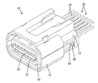
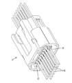
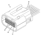
- FIG. 1 is a perspective view of the connector of the first embodiment.
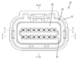
- FIG. 2 is a front view of the connector.
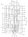
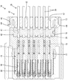
- FIG. 3 is a sectional view taken along line XX of FIG.
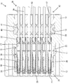
- FIG. 4 is a sectional view taken along line YY of FIG.
- FIG. 5 is a sectional view taken along line ZZ of FIG.
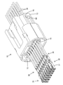
- FIG. 6 is a perspective view showing a disassembled state of the housing, the seal ring, the collective rubber plug, and the rear member.
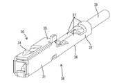
- FIG. 7 is a perspective view showing a state in which the terminal fitting is connected to the electric wire.
- FIG. 8 is a perspective view showing a state in which an electric wire to which a terminal fitting is not connected is inserted into the housing.
- FIG. 9 is a perspective view showing a state in which a terminal fitting is connected to an electric wire penetrating the housing.
- FIG. 10 is a perspective view showing a state where the terminal fitting connected to the electric wire is housed in the housing.
- the connector of the first disclosure is (1) A terminal fitting connected to a front end of an electric wire, a housing, and a collective rubber plug attached to a rear end of the housing are provided, and the terminal fitting is provided in the housing from the front of the housing. An accommodating chamber that allows insertion is formed, the collective rubber stopper has a seal hole, and the electric wire in a state where the terminal metal fitting is not connected can penetrate the accommodating chamber and the seal hole. is there.
- the terminal fitting can be housed in the housing chamber. Since it is not necessary to penetrate the terminal fitting into the seal hole, damage to the seal hole can be prevented.
- the terminal fitting has a terminal main body portion whose maximum outer dimension is larger than the outer diameter of the electric wire, the accommodation chamber has a narrow portion, and the electric wire can pass through the narrow portion. It is preferable that the terminal main body cannot penetrate the narrow portion. According to this configuration, even if the vibration is transmitted to the terminal fitting, the fluctuation of the electric wire in the accommodation chamber is suppressed at the narrow portion. As a result, deformation of the seal hole is suppressed, and high sealing performance is ensured.
- the narrow portion communicates with the front end of the seal hole and is arranged concentrically with the seal hole. If the narrow portion is adjacent to the seal hole in an eccentric positional relationship, there is a concern that the seal hole may be deformed improperly and the sealing performance may be deteriorated. However, according to the above configuration, since the sealing hole and the narrow portion are concentric, the sealing performance is high.
- the accommodating chamber has an accommodating recess that opens to the front end face of the housing, and the accommodating recess can accommodate the terminal main body portion, and the accommodating recess has the terminal main body portion. It is preferable that a retaining portion is formed that can come into contact with the front portion. According to this configuration, the rearward movement of the terminal fitting can be restricted by bringing the terminal main body into contact with the retaining portion.
- the accommodation recess communicates with the front end of the narrow portion and is eccentrically arranged with respect to the narrow portion. According to this configuration, since the accommodation recess and the narrow portion are eccentric, it is possible to secure a large area for the retaining portion and improve the function of retaining the terminal fitting.
- the terminal fitting has a terminal main body portion whose maximum outer dimension is larger than the outer diameter of the electric wire, and a rear member is provided behind the collective rubber plug, and the rear member is the It is preferable to have an electric wire through hole that allows the electric wire to penetrate and prevents the terminal main body from penetrating. According to this configuration, even if the electric wire vibrates behind the rear member, the electric wire shake is suppressed by the electric wire through hole. As a result, deformation of the seal hole is suppressed, and high sealing performance is ensured.
- the connector of the second disclosure is (7) A terminal fitting connected to the front end of the electric wire, a housing, and a rear member attached to the rear end of the housing are provided, and the terminal fitting has a maximum outer dimension larger than the outer diameter of the electric wire.
- the rear member is provided with a terminal main body, a housing chamber is formed in the housing through which the electric wire can pass, and which allows the terminal main body to be inserted from the front of the housing.
- An electric wire through hole is formed in the electric wire, and the electric wire in a state where the terminal fitting is not connected can penetrate through the electric wire through hole, and the terminal main body portion can penetrate through the electric wire through hole. It is impossible.
- the terminal fitting when the terminal fitting is connected to the electric wire penetrating the accommodating chamber and the electric wire is pulled rearward in that state, the terminal main body is accommodated in the accommodating chamber and the terminal fitting is attached to the housing.
- the terminal fitting When the terminal fitting is attached, it is sufficient to pull the wire, so that the buckling of the wire can be prevented.
- the electric wire through hole has a smaller diameter than the accommodating chamber in which the terminal main body is accommodated, the electric wire is guided by the electric wire through hole, so that blurring in the accommodating chamber is suppressed. As a result, the operation of inserting the terminal fitting into the accommodation chamber is smoothly performed. Therefore, workability when attaching the terminal fitting to the housing is good.
- a collective rubber plug having a seal hole is attached to a rear end portion of the housing, the rear member is disposed behind the collective rubber plug, and the terminal fitting is connected to the seal hole. It is preferable that an electric wire in a non-insulated state can be penetrated. According to this configuration, the electric wire is passed through the accommodation chamber and the seal hole, the terminal fitting is connected to the front end of the electric wire in the front of the housing, and after the terminal fitting is connected, the electric wire is pulled rearward to accommodate the terminal fitting. It can be housed indoors. Since it is not necessary to penetrate the terminal fitting into the seal hole, damage to the seal hole can be prevented.
- the accommodating chamber has a narrowed portion that allows the electric wire to pass therethrough and prevents the terminal main body from passing therethrough. According to this configuration, even if the vibration is transmitted to the terminal fitting, the fluctuation of the electric wire in the accommodation chamber is suppressed at the narrow portion. Thereby, the deformation of the seal hole is suppressed, and high sealing performance is secured.
- the narrow portion communicates with the front end of the seal hole and is arranged concentrically with the seal hole. If the narrow portion is adjacent to the seal hole in an eccentric positional relationship, there is a concern that the seal hole may be deformed improperly and the sealing performance may be deteriorated. However, according to the above configuration, since the sealing hole and the narrow portion are concentric, the sealing performance is high.
- the accommodating chamber has an accommodating recess that opens into the front end surface of the housing and that can accommodate the terminal main body, and the terminal main body can abut the accommodation recess from the front. It is preferable that a retaining portion is formed. According to this configuration, the rearward movement of the terminal fitting can be restricted by bringing the terminal main body into contact with the retaining portion.
- the accommodation recess communicates with a front end of the narrow portion and is eccentrically arranged with respect to the narrow portion. According to this configuration, since the accommodation recess and the narrow portion are eccentric, it is possible to secure a large area for the retaining portion and improve the function of retaining the terminal fitting.
- FIGS. 1 to 10 A first embodiment embodying the present disclosure will be described with reference to FIGS. 1 to 10. It should be noted that the present invention is not limited to these exemplifications, and is shown by the scope of the claims, and is intended to include meanings equivalent to the scope of the claims and all modifications within the scope.
- the left side in FIGS. 1, 3 to 10 is defined as the front side.
- the directions appearing in FIGS. 1 to 3 and 6 to 10 are defined as upper and lower as they are.
- the connector of the first embodiment includes one housing 10, one seal ring 23, one front member 24, a plurality of terminal fittings 30, one collective rubber plug 40, and one rear member 42. It is equipped with.
- the connector has a waterproof function due to the seal ring 23 and the collective rubber stopper 40.
- the housing 10 is made of a synthetic resin, and is a single component including a terminal accommodating portion 11, a cylindrical fitting portion 12, and a cylindrical accommodating portion 13.
- the terminal accommodating portion 11 has a block shape as a whole.
- the tubular fitting portion 12 surrounds the terminal accommodating portion 11 excluding the rear end portion.
- the tubular accommodating portion 13 has a form extending rearward from the outer peripheral edge of the rear end of the terminal accommodating portion 11 in a rectangular tubular shape.
- the inner space of the cylindrical housing portion 13 is a housing space 14 opened to the rear end surface of the housing 10.
- the rear end surface of the terminal accommodating portion 11 faces the accommodating space 14.
- the terminal accommodating portion 11 is formed with a plurality of accommodating chambers 15 that penetrate the terminal accommodating portion 11 (housing 10) in the front-rear direction.
- Each accommodating chamber 15 has an elongated shape in the front-rear direction as a whole, and is composed of an accommodating recess 16 that opens to the front end surface of the terminal accommodating portion 11 (housing 10) and a narrow portion 17 that communicates with the rear end of the accommodating recess 16.
- the cross-sectional shape (front view shape) obtained by cutting the accommodation recess 16 at a right angle to the penetrating direction (front-back direction) of the accommodation chamber 15 is a substantially rectangular shape.
- a first retaining portion 18 (retaining portion according to the claims) is formed at the front end portion of the upper wall portion of the inner wall surface of the accommodation recess 16. The first retaining portion 18 is arranged inside the accommodation chamber 15.
- the narrow portion 17 is composed of a low back portion 19 having a height dimension smaller than that of the accommodation recess 16, and an electric wire holding portion 20 communicating with the rear end of the low back portion 19.
- the low back portion 19 communicates with the rear end of the accommodation recess 16.
- the cross-sectional shape of the low back portion 19 cut at a right angle to the penetrating direction of the storage chamber 15 is a substantially rectangular shape.
- the width dimension of the low-height portion 19 is the same as the width dimension of the housing recessed portion 16, and the low-height portion 19 is arranged concentrically with the housing recessed portion 16 in the width direction (left-right direction).
- the height dimension of the low-back portion 19 is smaller than the height dimension of the accommodation recess 16, and the low-height portion 19 is arranged at a position eccentric to the accommodation recess 16 below in the height direction (vertical direction).
- the lower surface wall portion that constitutes the inner wall surface of the low-height portion 19 is flush with the lower surface wall portion that constitutes the inner wall surface of the accommodation recess 16. Therefore, the upper surface wall portion forming the inner wall surface of the low back portion 19 is lower than the lower surface wall portion of the accommodation recess 16 in a step shape.
- a second retaining portion 21 (retaining portion according to the claims) is formed on the rear end surface of the accommodating recess 16 due to the height difference between the upper surface wall portion of the accommodating recess portion 16 and the upper surface wall portion of the low back portion 19. ing.
- the second retaining portion 21, like the first retaining portion 18, is arranged in the accommodation chamber 15.
- the rear end of the wire holding portion 20 is opened to the rear end surface (in the housing space 14) of the terminal housing portion 11.
- the width dimension of the wire holding portion 20 is smaller than the width dimension of the low height portion 19, and the height dimension of the wire holding portion 20 is smaller than the height dimension of the low height portion 19.
- a guide surface 22 is formed on the inner circumference of the rear end of the wire holding portion 20 so that the diameter gradually increases toward the rear.
- the rear end of the guide surface 22 faces the accommodation space 14.
- the guide surface 22 guides the electric wire 39 into the electric wire holding portion 20 by slidingly contacting the front end portion of the electric wire 39.
- the seal ring 23 is attached to the outer periphery of the terminal accommodating portion 11 from the front of the housing 10.
- the front member 24 is made of a synthetic resin, and is a single component having a front wall portion 25 and a rectangular tubular outer fitting portion 26 extending rearward from the outer peripheral edge of the front wall portion 25.
- the front member 24 is assembled from the front of the terminal accommodating portion 11 (housing 10).
- the outer fitting portion 26 surrounds the terminal accommodating portion 11 and restricts the seal ring 23 from being detached forward.
- the front wall portion 25 is in a state of closing the opening on the front surface of the accommodation chamber 15 (accommodation concave portion 16).
- the front wall portion 25 is formed with a plurality of tab insertion openings 27 that individually correspond to the plurality of accommodation chambers 15 (accommodation recesses 16).
- the terminal fitting 30 is a single component that has a rectangular tube-shaped terminal body 31 and an open barrel-shaped wire crimping portion 32 that is elongated in the front-rear direction as a whole.
- a tab of a mating terminal (not shown) that penetrates the tab insertion opening 27 is inserted into the terminal body 31.
- An elastic contact piece 33 capable of elastically contacting the tab is accommodated inside the terminal body 31.
- the width dimension of the terminal main body 31 is slightly smaller than the width dimensions of the accommodation recess 16 and the low back portion 19.
- the height dimension of the terminal main body portion 31 is slightly smaller than the height dimension of the accommodating concave portion 16 and larger than the height dimension of the low back portion 19.
- a cut-and-raised first locking portion 34 is formed at the front end of the upper surface of the terminal body 31.
- the first locking portion 34 In a state where the terminal fitting 30 is properly housed in the housing chamber 15, the first locking portion 34 is in a positional relationship capable of being locked to the first retaining portion 18 from the front.
- the rear end portion of the upper plate portion that constitutes the terminal main body portion 31 functions as the second locking portion 35.
- the second locking portion 35 is in a positional relationship capable of being locked from the front with respect to the second retaining portion 21.
- the first locking portion 34 is hooked on the first retaining portion 18, or the second locking portion 35 is hooked on the second retaining portion 21, so that the terminal fitting 30 moves rearward with respect to the housing 10. To be restricted.
- the electric wire crimping portion 32 has a cantilevered shape extending rearward from the rear end of the terminal body 31.
- the wire crimping portion 32 includes a board portion 36 that extends rearward from the rear end of the lower plate portion that constitutes the terminal body portion 31 so as to be flush, and a crimping piece 37 that extends from both left and right edges of the board portion 36.
- the electric wire 39 is crimped to the electric wire crimping portion 32 so that the front end portion of the electric wire 39 can be conducted and the relative movement in the front-rear direction is restricted. Thereby, as shown in FIG. 7, a conductive path 38 in which the terminal fitting 30 and the electric wire 39 are integrated is formed.
- the electric wire 39 fixed to the electric wire crimping portion 32 (the rear end portion of the terminal fitting 30) has a form extending rearward from the terminal fitting 30.
- the width dimension of the wire crimping portion 32 in the state where the wire 39 is crimped is the same as or slightly smaller than the width dimension of the terminal body portion 31.
- the height dimension of the wire crimping portion 32 in the state where the electric wire 39 is crimped is smaller than the height dimension of the terminal main body portion 31, and the second locking portion 35 is formed by the difference in the height dimension. Further, the height dimension of the wire crimping portion 32 in the state where the electric wire 39 is crimped is slightly smaller than the height dimension of the low back portion 19.
- the terminal main body 31 and the electric wire crimping portion 32 are eccentric in the vertical direction (height direction).
- the larger dimension of the width dimension and the height dimension of the terminal accommodating portion 11 is defined as the maximum outer dimension of the terminal fitting 30.
- the outer diameter dimension of the electric wire 39 is smaller than the maximum outer dimension of the terminal fitting 30.
- the outer diameter of the electric wire 39 is the same as or slightly smaller than the width and height of the electric wire holding portion 20 of the housing 10.
- the width dimension and the height dimension of the wire crimping portion 32 in the state where the wire 39 is crimped are larger than the width dimension and the height dimension of the wire holding portion 20.
- the collective rubber plug 40 is attached to the housing 10 from the rear and is housed in the housing space 14.
- the outer periphery of the collective rubber stopper 40 comes into liquid-tight contact with the inner peripheral surface of the accommodation space 14 (cylindrical accommodation portion 13 ). Further, the front end surface of the collective rubber plug 40 contacts the rear end surface (the rear end surface of the accommodation space 14) of the terminal accommodating portion 11.
- the collective rubber plug 40 is formed with a plurality of seal holes 41 that penetrate the collective rubber plug 40 in the front-rear direction.
- the plurality of seal holes 41 are arranged so as to individually adjoin behind the rear ends (the electric wire holding portions 20) of the plurality of storage chambers 15.
- the cross-sectional shape of the seal hole 41 cut at a right angle to the front-rear direction is circular.
- the minimum inner diameter of the seal hole 41 is smaller than the maximum outer dimension of the terminal fitting 30 and the outer diameter dimension of the electric wire 39.
- the seal hole 41 is arranged concentrically with the housing chamber 15 (electric wire holding portion 20) in the left-right direction.
- the seal hole 41 is arranged concentrically with the narrow portion 17 (the low back portion 19 and the wire holding portion 20) in the height direction, and is arranged eccentrically downward with respect to the accommodation recess 16.
- the rear member 42 is a single component having the pressing portion 43 and the pair of elastic lock pieces 44.
- the holding portion 43 has the same rear view shape as the accommodation space 14.
- the pair of elastic lock pieces 44 are cantilevered forward from the left and right ends of the pressing portion 43.
- the rear member 42 is attached to the housing 10 in a state of being housed in the rear end portion of the housing space 14 (cylindrical housing portion 13).
- the front end surface of the pressing portion 43 abuts on the rear end surface of the collective rubber plug 40.
- the collective rubber plug 40 is held in the assembled state in which the relative displacement to the rear is restricted with respect to the housing 10.
- the elastic lock piece 44 in the lock hole 46 of the cylindrical accommodating portion 13
- the rear member 42 is held in the assembled state in the housing 10.
- the rear member 42 is formed with a plurality of wire through holes 47 that penetrate the rear member 42 in the front-rear direction.
- the plurality of electric wire through holes 47 are arranged so as to individually adjoin behind the rear ends of the plurality of seal holes 41.
- the cross-sectional shape of the wire through hole 47 cut at a right angle to the front-rear direction is circular.
- the minimum inner diameter of the wire through hole 47 is larger than the outer diameter dimension of the wire 39 and the minimum inner diameter of the seal hole 41, and smaller than the maximum outer dimension of the terminal fitting 30.
- the electric wire through hole 47 is arranged concentrically with the seal hole 41 and the narrow portion 17 (the low back portion 19 and the electric wire holding portion 20) in the width direction (horizontal direction) and the height direction (vertical direction).
- the wire through hole 47 is arranged concentrically with the housing recess 16 in the height direction, and is arranged eccentrically downward with respect to the housing recess 16.
- the seal ring 23, the collective rubber plug 40, and the rear member 42 are assembled to the housing 10, and in this state, a plurality of electric wires 39 are sealed from the rear of the housing 10 (rear member 42) to the electric wire through hole 47.
- the hole 41 and the accommodation chamber 15 are inserted (see FIG. 8).
- the wire crimping portion 32 of each terminal fitting 30 is fixed to the front end portion of the wire 39.
- the conductive path 38 in which the electric wire 39 is passed through the housing 10 is manufactured. After that, when the portion of the electric wire 39 that is led out to the rear of the housing 10 is pulled rearward, the conductive path 38 relatively moves rearward with respect to the housing 10, and the conductive path 38 (the terminal fitting 30 and the electric wire 39) is moved. It is assembled to the housing 10.
- the terminal fitting 30 is placed in front of the housing 10.
- the storage recess 16 is approached.
- the wire through hole 47, the seal hole 41, and the narrow portion 17 are lined up in the front and rear so as to be concentric in the width direction and the height direction, the wire 39 does not bend and remains straight. Move backwards.
- the movement trajectory of the terminal fitting 30 in front of the housing 10 also becomes substantially linear.
- the accommodation recess 16 is opened on the rear extension line of the movement path of the terminal fitting 30.
- the terminal body 31 is housed in the housing recess 16 without interfering with the front end surface of the terminal housing 11 (housing 10) (see FIG. 10).
- the first locking portion 34 locks the first retaining portion 18 from the front, and the second locking portion 35 moves to the second position.
- the retaining portion 21 is locked from the front, and the further rearward movement of the terminal fitting 30 is restricted.
- the assembly of the conductive path 38 to the housing 10 is completed.
- the portion of the wire crimping portion 32 and the wire 39 crimped to the wire crimping portion 32 is accommodated in the narrow portion 17, and the wire crimping portion of the wire 39 is accommodated.
- a portion behind 32 is inserted into the wire holding portion 20, the seal hole 41, and the wire through hole 47.
- the front member 24 is assembled to the housing 10 from the front.
- the front wall portion 25 closes the opening of the front end of the housing recess 16 and approaches the front end surface of the terminal body portion 31 so as to face and face it.
- the terminal fitting 30 is restricted from moving forward relative to the housing 10.
- the connector of the first embodiment has a terminal fitting 30 connectable to the front end of the electric wire 39 and a housing 10.
- a housing chamber 15 is formed in the housing 10 to allow the terminal fitting 30 to be inserted from the front of the housing 10.
- a collective rubber plug 40 having a seal hole 41 is attached to the rear end of the housing 10.
- An electric wire 39 in a state where the terminal fitting 30 is not connected can pass through the housing chamber 15 and the seal hole 41.
- the electric wire 39 is passed through the accommodation chamber 15 and the seal hole 41, the terminal fitting 30 is connected to the front end of the electric wire 39 in the front of the housing 10, and after the terminal fitting 30 is connected, the electric wire 39 is moved backward.
- the terminal fitting 30 can be housed in the housing chamber 15 by pulling to. Since it is not necessary to penetrate the terminal fitting 30 into the seal hole 41, damage to the seal hole 41 can be prevented.
- the terminal fitting 30 has a terminal main body 31 whose maximum outer dimension is larger than the outer diameter of the electric wire 39, and the accommodation chamber 15 allows the electric wire 39 to penetrate therethrough, but does not allow the terminal main body 31 to penetrate therethrough.
- the narrow portion 17 has According to this configuration, even if the vibration is transmitted to the terminal fitting 30, the narrow portion 17 suppresses the movement of the electric wire 39 in the housing chamber 15. As a result, illegal deformation of the seal hole 41 is suppressed, and high sealing performance is ensured.
- the narrow portion 17 communicates with the front end of the seal hole 41 and is arranged concentrically with respect to the seal hole 41, so that unauthorized deformation of the seal hole 41 is restricted. Demonstrate high sealing performance.
- the accommodation chamber 15 has an accommodation recess 16 that opens to the front end surface of the housing 10.
- the accommodation recess 16 can accommodate the terminal main body 31.
- the housing recess 16 is formed with a first retaining portion 18 and a second retaining portion 21 with which the terminal body portion 31 can abut from the front. According to this structure, the rearward movement of the terminal fitting 30 can be restricted by bringing the terminal main body 31 into contact with the first retaining portion 18 and the second retaining portion 21.
- the accommodation recess 16 communicates with the front end of the narrow portion 17 and is arranged eccentrically with respect to the narrow portion 17, it is possible to secure a large area for the second retaining portion 21. As a result, the function of retaining the terminal fitting 30 is improved.
- the terminal fitting 30 has a terminal main body 31 whose maximum outer dimension is larger than the outer diameter of the electric wire 39.
- a rear member 42 is provided behind the collective rubber plug 40.
- the rear member 42 has an electric wire through hole 47 through which the electric wire 39 can be penetrated and the terminal main body portion 31 cannot be penetrated. According to this configuration, even if the electric wire 39 vibrates behind the rear member 42, the electric wire 39 is prevented from being shaken by the electric wire through hole 47. As a result, deformation of the seal hole 41 is suppressed, and high sealing performance is ensured.
- the connector according to the first embodiment also has the following features. That is, the terminal fitting 30 is connectable to the front end portion of the electric wire 39 and has the terminal main body portion 31 whose maximum outer dimension is larger than the outer diameter of the electric wire 39.
- a housing chamber 15 is formed in the housing 10.
- An electric wire 39 can pass through the accommodation chamber 15.
- the accommodation chamber 15 allows the terminal body 31 to be inserted from the front of the housing 10.
- a rear member 42 is attached to the rear end of the housing 10, and an electric wire through hole 47 is formed in the rear member 42.
- the electric wire 39 to which the terminal fitting 30 is not connected can pass through the electric wire through hole 47.
- the terminal body 31 cannot penetrate the wire through hole 47.
- the terminal fitting 30 when the terminal fitting 30 is connected to the electric wire 39 penetrating the accommodating chamber 15, and the electric wire 39 is pulled rearward in that state, the terminal body 31 is accommodated in the accommodating chamber 15 and the terminal fitting 30 is It is attached to the housing 10.
- the electric wire 39 may be pulled, so that the electric wire 39 can be prevented from buckling.
- the wire through-hole 47 since the wire through-hole 47 has a smaller diameter than the housing chamber 15 in which the terminal body 31 is housed, the wire 39 is guided by the wire through-hole 47, so that blurring in the housing chamber 15 is suppressed. Accordingly, the inserting operation of the terminal fitting 30 into the accommodation chamber 15 is smoothly performed. Therefore, the workability in attaching the terminal fitting 30 to the housing 10 is good.
- the accommodation recess is eccentric with respect to the seal hole, but according to the first aspect, the accommodation recess may be concentric with the seal hole.
- the accommodation recess is eccentric with respect to the narrow portion, but according to the first and second aspects of the invention, the accommodation recess may be concentric with the narrow portion.
- the narrow portion and the seal hole are arranged concentrically, but according to the first invention, the narrow portion and the seal hole may be eccentric.
- the accommodating chamber has the narrow portion that does not allow the terminal main body portion to penetrate, but according to the first and second inventions, the accommodating chamber does not have the narrow portion. It may be in the form.
- the retaining portions are formed at the front end portion and the rear end portion of the accommodation recess, but according to the first and second inventions, the retaining portion is formed in the front-back direction of the accommodation recess. May be formed in the central portion of the above, or may be formed in a portion other than the accommodation recess.
- the retaining portion is formed inside the accommodation chamber, but according to the first and second aspects, the retaining portion is formed outside (front) the accommodation chamber. May be.
- the maximum outer dimension of the terminal fitting is larger than the outer diameter of the electric wire.
- the size may be the same or smaller than the outer diameter of the electric wire.
- almost the entire terminal fitting (a portion of the terminal fitting excluding the front end portion) is housed in the housing chamber. However, according to the first and second inventions, the entire terminal fitting is provided. May be housed in the housing chamber.
- the terminal body of the terminal fitting and the wire crimping portion are eccentric, but according to the first and second aspects of the invention, even if the terminal body and the wire crimping portion are concentric. Good.
- the terminal fitting is a female terminal in which the elastic contact piece is housed in the terminal body, but in the first and second inventions, the terminal fitting has a tab at the front end. It can also be applied to the case of a male terminal.
- the electric wire through hole of the rear holder regulates the penetration of the terminal fitting (terminal body portion). ) May be allowed.
- the electric wire and the terminal fitting are connected by crimping, but according to the first and second inventions, the electric wire and the terminal fitting may be connected by means such as welding.
- the front member attached to the housing regulates the detachment of the terminal fitting to the front.
- the elastic locking piece that is elastically displaceable in the housing. It is also possible to regulate the detachment of the terminal fitting to the front by forming the above and hooking the terminal fitting on this elastic locking piece.
- the front stop member (front member) for restricting the forward detachment of the terminal fitting is arranged at the front end portion of the housing, but according to the first and second inventions.
- the front stop member may be arranged at a position rearward of the front end of the housing.
- the front stop member may be formed with a portion that contacts the front stop portion in a region rearward of the front end of the terminal fitting.
Landscapes
- Connector Housings Or Holding Contact Members (AREA)
Priority Applications (2)
| Application Number | Priority Date | Filing Date | Title |
|---|---|---|---|
| US17/296,407 US20220029349A1 (en) | 2018-12-04 | 2019-11-13 | Connector |
| CN201980079531.5A CN113169479A (zh) | 2018-12-04 | 2019-11-13 | 连接器 |
Applications Claiming Priority (2)
| Application Number | Priority Date | Filing Date | Title |
|---|---|---|---|
| JP2018-227021 | 2018-12-04 | ||
| JP2018227021A JP2020091964A (ja) | 2018-12-04 | 2018-12-04 | コネクタ |
Publications (1)
| Publication Number | Publication Date |
|---|---|
| WO2020116112A1 true WO2020116112A1 (ja) | 2020-06-11 |
Family
ID=70975425
Family Applications (1)
| Application Number | Title | Priority Date | Filing Date |
|---|---|---|---|
| PCT/JP2019/044531 Ceased WO2020116112A1 (ja) | 2018-12-04 | 2019-11-13 | コネクタ |
Country Status (4)
| Country | Link |
|---|---|
| US (1) | US20220029349A1 (enExample) |
| JP (1) | JP2020091964A (enExample) |
| CN (1) | CN113169479A (enExample) |
| WO (1) | WO2020116112A1 (enExample) |
Families Citing this family (3)
| Publication number | Priority date | Publication date | Assignee | Title |
|---|---|---|---|---|
| JP7541282B2 (ja) * | 2021-01-25 | 2024-08-28 | 住友電装株式会社 | コネクタ |
| CN117096651A (zh) * | 2022-05-12 | 2023-11-21 | 苏州德斯米尔智能科技有限公司 | 一种具有橡胶塞式的线束端口 |
| US12266885B2 (en) | 2022-12-12 | 2025-04-01 | Aptiv Technologies AG | Seal retainer with seal expansion compensation features |
Citations (3)
| Publication number | Priority date | Publication date | Assignee | Title |
|---|---|---|---|---|
| JPH11288756A (ja) * | 1998-03-31 | 1999-10-19 | Yazaki Corp | 防水コネクタ及び防水コネクタの組立方法 |
| JP2012018802A (ja) * | 2010-07-07 | 2012-01-26 | Sumitomo Wiring Syst Ltd | コネクタ |
| JP2014078431A (ja) * | 2012-10-11 | 2014-05-01 | Furukawa Electric Co Ltd:The | コネクタの製造方法 |
Family Cites Families (6)
| Publication number | Priority date | Publication date | Assignee | Title |
|---|---|---|---|---|
| JP2000348815A (ja) * | 1999-06-03 | 2000-12-15 | Yazaki Corp | 防水コネクタ及び該防水コネクタの組付方法 |
| JP5766644B2 (ja) * | 2012-03-26 | 2015-08-19 | 株式会社フジクラ | 編組シールド電線の接続構造及びシールドワイヤハーネスの製造方法 |
| JP2014075202A (ja) * | 2012-10-02 | 2014-04-24 | Sumitomo Wiring Syst Ltd | ゴム栓及びゴム栓付き端子金具 |
| JP6536902B2 (ja) * | 2016-02-12 | 2019-07-03 | 住友電装株式会社 | 防水コネクタ |
| JP2018125193A (ja) * | 2017-02-01 | 2018-08-09 | 住友電装株式会社 | 防水コネクタ |
| JP2018133278A (ja) * | 2017-02-17 | 2018-08-23 | 住友電装株式会社 | 充電インレット |
-
2018
- 2018-12-04 JP JP2018227021A patent/JP2020091964A/ja active Pending
-
2019
- 2019-11-13 US US17/296,407 patent/US20220029349A1/en not_active Abandoned
- 2019-11-13 WO PCT/JP2019/044531 patent/WO2020116112A1/ja not_active Ceased
- 2019-11-13 CN CN201980079531.5A patent/CN113169479A/zh active Pending
Patent Citations (3)
| Publication number | Priority date | Publication date | Assignee | Title |
|---|---|---|---|---|
| JPH11288756A (ja) * | 1998-03-31 | 1999-10-19 | Yazaki Corp | 防水コネクタ及び防水コネクタの組立方法 |
| JP2012018802A (ja) * | 2010-07-07 | 2012-01-26 | Sumitomo Wiring Syst Ltd | コネクタ |
| JP2014078431A (ja) * | 2012-10-11 | 2014-05-01 | Furukawa Electric Co Ltd:The | コネクタの製造方法 |
Also Published As
| Publication number | Publication date |
|---|---|
| JP2020091964A (ja) | 2020-06-11 |
| CN113169479A (zh) | 2021-07-23 |
| US20220029349A1 (en) | 2022-01-27 |
Similar Documents
| Publication | Publication Date | Title |
|---|---|---|
| JP5189941B2 (ja) | コネクタ | |
| US9407025B2 (en) | Connector | |
| US20140127928A1 (en) | Connector | |
| JP4259453B2 (ja) | 防水コネクタ | |
| CN110556668B (zh) | 连接器 | |
| WO2018163788A1 (ja) | シールド端子及びシールドコネクタ | |
| WO2018163787A1 (ja) | シールド端子及びシールドコネクタ | |
| JP5093088B2 (ja) | 防水コネクタ | |
| WO2018168367A1 (ja) | 端子ユニット及びコネクタ | |
| WO2020116112A1 (ja) | コネクタ | |
| JP2014093221A (ja) | コネクタ | |
| JP5556568B2 (ja) | コネクタ | |
| JP2010238514A (ja) | 防水コネクタ | |
| CN111262084A (zh) | 连接器 | |
| US20230102502A1 (en) | Connector | |
| WO2020105382A1 (ja) | コネクタ | |
| JP5594008B2 (ja) | コネクタ | |
| JP4725505B2 (ja) | コネクタ及び端子金具 | |
| JP5440462B2 (ja) | コネクタ | |
| US12294174B2 (en) | Connector with ferrite core-receiving housing | |
| JP2010020935A (ja) | シールドコネクタ | |
| JP7243551B2 (ja) | コネクタ | |
| JP7230753B2 (ja) | コネクタ | |
| JP2010097765A (ja) | コネクタ | |
| JP3777980B2 (ja) | 分割コネクタ |
Legal Events
| Date | Code | Title | Description |
|---|---|---|---|
| 121 | Ep: the epo has been informed by wipo that ep was designated in this application |
Ref document number: 19891698 Country of ref document: EP Kind code of ref document: A1 |
|
| NENP | Non-entry into the national phase |
Ref country code: DE |
|
| 122 | Ep: pct application non-entry in european phase |
Ref document number: 19891698 Country of ref document: EP Kind code of ref document: A1 |