WO2020110522A1 - 走行車システム - Google Patents
走行車システム Download PDFInfo
- Publication number
- WO2020110522A1 WO2020110522A1 PCT/JP2019/041503 JP2019041503W WO2020110522A1 WO 2020110522 A1 WO2020110522 A1 WO 2020110522A1 JP 2019041503 W JP2019041503 W JP 2019041503W WO 2020110522 A1 WO2020110522 A1 WO 2020110522A1
- Authority
- WO
- WIPO (PCT)
- Prior art keywords
- track
- guide surface
- traveling
- guide
- connection
- Prior art date
- Legal status (The legal status is an assumption and is not a legal conclusion. Google has not performed a legal analysis and makes no representation as to the accuracy of the status listed.)
- Ceased
Links
Images








Classifications
-
- B—PERFORMING OPERATIONS; TRANSPORTING
- B61—RAILWAYS
- B61B—RAILWAY SYSTEMS; EQUIPMENT THEREFOR NOT OTHERWISE PROVIDED FOR
- B61B3/00—Elevated railway systems with suspended vehicles
- B61B3/02—Elevated railway systems with suspended vehicles with self-propelled vehicles
-
- B—PERFORMING OPERATIONS; TRANSPORTING
- B61—RAILWAYS
- B61B—RAILWAY SYSTEMS; EQUIPMENT THEREFOR NOT OTHERWISE PROVIDED FOR
- B61B13/00—Other railway systems
- B61B13/02—Rack railways
-
- B—PERFORMING OPERATIONS; TRANSPORTING
- B65—CONVEYING; PACKING; STORING; HANDLING THIN OR FILAMENTARY MATERIAL
- B65G—TRANSPORT OR STORAGE DEVICES, e.g. CONVEYORS FOR LOADING OR TIPPING, SHOP CONVEYOR SYSTEMS OR PNEUMATIC TUBE CONVEYORS
- B65G1/00—Storing articles, individually or in orderly arrangement, in warehouses or magazines
- B65G1/02—Storage devices
- B65G1/04—Storage devices mechanical
- B65G1/0457—Storage devices mechanical with suspended load carriers
-
- B—PERFORMING OPERATIONS; TRANSPORTING
- B66—HOISTING; LIFTING; HAULING
- B66C—CRANES; LOAD-ENGAGING ELEMENTS OR DEVICES FOR CRANES, CAPSTANS, WINCHES, OR TACKLES
- B66C17/00—Overhead travelling cranes comprising one or more substantially horizontal girders the ends of which are directly supported by wheels or rollers running on tracks carried by spaced supports
- B66C17/06—Overhead travelling cranes comprising one or more substantially horizontal girders the ends of which are directly supported by wheels or rollers running on tracks carried by spaced supports specially adapted for particular purposes, e.g. in foundries, forges; combined with auxiliary apparatus serving particular purposes
-
- B—PERFORMING OPERATIONS; TRANSPORTING
- B66—HOISTING; LIFTING; HAULING
- B66C—CRANES; LOAD-ENGAGING ELEMENTS OR DEVICES FOR CRANES, CAPSTANS, WINCHES, OR TACKLES
- B66C7/00—Runways, tracks or trackways for trolleys or cranes
- B66C7/02—Runways, tracks or trackways for trolleys or cranes for underhung trolleys or cranes
-
- H—ELECTRICITY
- H10—SEMICONDUCTOR DEVICES; ELECTRIC SOLID-STATE DEVICES NOT OTHERWISE PROVIDED FOR
- H10P—GENERIC PROCESSES OR APPARATUS FOR THE MANUFACTURE OR TREATMENT OF DEVICES COVERED BY CLASS H10
- H10P72/00—Handling or holding of wafers, substrates or devices during manufacture or treatment thereof
- H10P72/30—Handling or holding of wafers, substrates or devices during manufacture or treatment thereof for conveying, e.g. between different workstations
- H10P72/32—Handling or holding of wafers, substrates or devices during manufacture or treatment thereof for conveying, e.g. between different workstations between different workstations
- H10P72/3202—Mechanical details, e.g. rollers or belts
-
- H—ELECTRICITY
- H10—SEMICONDUCTOR DEVICES; ELECTRIC SOLID-STATE DEVICES NOT OTHERWISE PROVIDED FOR
- H10P—GENERIC PROCESSES OR APPARATUS FOR THE MANUFACTURE OR TREATMENT OF DEVICES COVERED BY CLASS H10
- H10P72/00—Handling or holding of wafers, substrates or devices during manufacture or treatment thereof
- H10P72/30—Handling or holding of wafers, substrates or devices during manufacture or treatment thereof for conveying, e.g. between different workstations
- H10P72/32—Handling or holding of wafers, substrates or devices during manufacture or treatment thereof for conveying, e.g. between different workstations between different workstations
- H10P72/3208—Changing the direction of the conveying path
-
- H—ELECTRICITY
- H10—SEMICONDUCTOR DEVICES; ELECTRIC SOLID-STATE DEVICES NOT OTHERWISE PROVIDED FOR
- H10P—GENERIC PROCESSES OR APPARATUS FOR THE MANUFACTURE OR TREATMENT OF DEVICES COVERED BY CLASS H10
- H10P72/00—Handling or holding of wafers, substrates or devices during manufacture or treatment thereof
- H10P72/30—Handling or holding of wafers, substrates or devices during manufacture or treatment thereof for conveying, e.g. between different workstations
- H10P72/32—Handling or holding of wafers, substrates or devices during manufacture or treatment thereof for conveying, e.g. between different workstations between different workstations
- H10P72/3218—Conveying cassettes, containers or carriers
-
- H—ELECTRICITY
- H10—SEMICONDUCTOR DEVICES; ELECTRIC SOLID-STATE DEVICES NOT OTHERWISE PROVIDED FOR
- H10P—GENERIC PROCESSES OR APPARATUS FOR THE MANUFACTURE OR TREATMENT OF DEVICES COVERED BY CLASS H10
- H10P72/00—Handling or holding of wafers, substrates or devices during manufacture or treatment thereof
- H10P72/30—Handling or holding of wafers, substrates or devices during manufacture or treatment thereof for conveying, e.g. between different workstations
- H10P72/32—Handling or holding of wafers, substrates or devices during manufacture or treatment thereof for conveying, e.g. between different workstations between different workstations
- H10P72/3221—Overhead conveying
-
- B—PERFORMING OPERATIONS; TRANSPORTING
- B65—CONVEYING; PACKING; STORING; HANDLING THIN OR FILAMENTARY MATERIAL
- B65G—TRANSPORT OR STORAGE DEVICES, e.g. CONVEYORS FOR LOADING OR TIPPING, SHOP CONVEYOR SYSTEMS OR PNEUMATIC TUBE CONVEYORS
- B65G2201/00—Indexing codes relating to handling devices, e.g. conveyors, characterised by the type of product or load being conveyed or handled
- B65G2201/02—Articles
- B65G2201/0297—Wafer cassette
Definitions
- the present invention relates to a traveling vehicle system.
- a traveling vehicle system in which a traveling vehicle conveys an article such as a FOUP containing a semiconductor wafer or a reticle Pod containing a reticle is used.
- a traveling vehicle system a first track extending along a first direction, a second track extending along a second direction different from the first direction, a first track and a second track are provided.
- a configuration including a direction changing mechanism that integrally rotates a connecting portion is known (see, for example, Patent Document 1).
- the main body portion may not be displaced in a direction intersecting with the traveling direction when the traveling vehicle travels on the first track and the second track. It has been demanded. Therefore, a configuration in which a guide roller or the like is arranged on the traveling vehicle and the guide roller rolls on a guide surface provided along the track to suppress the displacement of the main body can be considered.
- a mechanism for separately changing the direction of the guide roller is provided in accordance with the direction change of the traveling wheels. There is a problem that the structure of the traveling vehicle becomes complicated. Further, if the height dimension of the traveling vehicle is increased by disposing the guide rollers, it becomes a factor of reducing the space efficiency in the vicinity of the ceiling of the building or the like in which the traveling vehicle system is installed.
- An object of the present invention is to provide a traveling vehicle system capable of suppressing the displacement of the main body with a simple configuration while avoiding a complicated configuration of the traveling vehicle.
- a traveling vehicle system has a first track that extends along a first direction, a second track that extends along a second direction different from the first direction, and a first track.
- a track having a first track and a track track that are adjacent to the second track in the second direction and that are connected to each other with a gap between each of the first track and the second track.
- a traveling vehicle system comprising: an overhead traveling vehicle traveling along a track, wherein the track has a first guide surface provided along the first track and a second guide provided along the second track.
- the overhead traveling vehicle includes a traveling wheel that rolls on a first track, a second track, and a connecting track, a main body portion that is disposed below the track, and an axle of the traveling wheel.
- a direction changing mechanism that switches between a first state in which the vehicle rolls on the track and a second state in which the traveling wheels roll on the second track, and a connecting portion, which is provided in the connecting portion, and is provided on the first guide surface in the first state. And a guide portion that moves along the second guide surface in the second state.
- first guide surface may be a side surface of the first track
- second guide surface may be a side surface of the second track.
- the guide portion is disposed at a height between the axle of the traveling wheel and the main body portion, and the first guide surface and the second guide surface are disposed at a height between the axle of the traveling wheel and the main body portion. It may be arranged. Further, the guide portion may be a guide roller capable of rolling when it comes into contact with the first guide surface or the second guide surface.
- connection track has a first connection guide surface provided at the same height and in the same direction as the first guide surface, and a second connection guide surface provided at the same height and in the same direction as the second guide surface, May have.
- connection track may include a continuous surface that connects the first connection guide surface and the second connection guide surface.
- the continuous surface may be a curved surface that smoothly connects the first connection guide surface and the second connection guide surface.
- the main body may have a rectangular shape when viewed in the axial direction of the turning shaft of the connecting portion, and may have traveling wheels, a connecting portion, a direction changing mechanism, and a guide portion at each of the four corner portions.
- the distance between the two guide portions arranged in the traveling direction of the overhead traveling vehicle may be different from the distance between two adjacent gaps in the first direction or the second direction.
- the guide portion turns together with the connecting portion, so that the guide portion can be changed according to the direction change of the traveling wheels without separately providing a configuration for changing the direction of the guide portion.
- the direction of can be switched.
- the displacement of the main body can be suppressed with a simple structure while avoiding a complicated structure of the traveling vehicle.
- the side surfaces of the first track and the second track are the first guide surface and the second guide.
- the guide portion is arranged at a height between the axle of the traveling wheel and the body portion, and the first guide surface and the second guide surface are arranged at a height between the axle of the traveling wheel and the body portion.
- connection track has a first connection guide surface provided at the same height and in the same direction as the first guide surface, and a second connection guide surface provided at the same height and in the same direction as the second guide surface,
- the position deviation of the main body portion can be suppressed by the guide portion contacting the first connection guide surface or the second guide surface even in the connection track.
- the connection track includes the continuous surface that connects the first connection guide surface and the second connection guide surface, when the traveling wheel turns by the direction changing mechanism, the guide portion is moved along the continuous surface. As a result, it is possible to suppress the displacement of the main body when the traveling wheels turn.
- the continuous surface is a curved surface that smoothly connects the first connection guide surface and the second connection guide surface
- smooth movement of the guide portion on the continuous surface can be ensured.
- the main body has a rectangular shape when viewed from the axial direction of the turning axis of the connecting portion and each of the four corners has the traveling wheel, the connecting portion, the direction changing mechanism, and the guide portion
- the guide portions arranged at the four corners can suppress the displacement of the main body portion around the vertical axis with respect to the track.
- the two guide portions arranged in the traveling direction of the overhead traveling vehicle form the gap at the same time. Can be prevented from being located at.
- the direction perpendicular to the XY plane is referred to as the Z direction.
- the direction indicated by the arrow in the drawing is the + direction
- the direction opposite to the direction indicated by the arrow is the ⁇ direction.
- the turning direction around the vertical axis or the Z axis is referred to as the ⁇ Z direction.
- FIG. 1 is a side view showing an example of a traveling vehicle system SYS according to the present embodiment.
- FIG. 2 is a perspective view of an overhead traveling vehicle 100 used in the traveling vehicle system SYS shown in FIG.
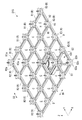
- FIG. 3 is a perspective view showing an example of the traveling vehicle system SYS according to the present embodiment.
- an overhead traveling vehicle 100 moves along a track R of a traveling vehicle system SYS and conveys an article M such as a FOUP containing a semiconductor wafer or a reticle Pod containing a reticle. .. Since the overhead traveling vehicle 100 transports the article M, it may be referred to as an overhead traveling vehicle.
- the traveling vehicle system SYS is a system for transporting the article M by the overhead traveling vehicle 100 in a clean room of a semiconductor manufacturing factory, for example.
- a plurality of overhead traveling vehicles 100 may be used, for example.
- the orbit R is a form of the orbit.
- the track R is laid on or near the ceiling of a building such as a clean room.
- the trajectory R is a lattice trajectory having a first trajectory R1, a second trajectory R2, and a connecting trajectory R3 (see FIG. 3).
- the trajectory R will be referred to as a lattice trajectory R.
- the first track R1 is provided along the X direction (first direction D1).
- the second track R2 is provided along the Y direction (second direction D2).
- the first direction D1 and the second direction D2 are orthogonal to each other, and the plurality of first trajectories R1 and the plurality of second trajectories R2 are orthogonal to each other.
- the connecting track R3 is arranged at the intersection of the first track R1 and the second track R2.
- the connecting track R3 is adjacent to the first track R1 in the first direction D1 and is adjacent to the second track R2 in the second direction D2.
- the connecting track R3 connects the first track R1 and the second track R2.
- the first orbit R1 and the second orbit R2 are orthogonal to each other, so that a plurality of cells C are adjacent to each other in a plan view.
- FIG. 3 shows a part of the lattice-shaped orbit R, and the lattice-shaped orbit R has the same configuration in the first direction D1 (X direction) and the second direction D2 (Y direction) from the configuration shown in the drawing. Are continuously formed.
- the first track R1, the second track R2, and the connecting track R3 are suspended by a suspension member H (see FIG. 3) on a ceiling (not shown).
- the suspending member H includes a first portion H1 for suspending the first track R1, a second portion H2 for suspending the second track R2, and a third portion H3 for suspending the connecting track R3.
- the first portion H1 and the second portion H2 are respectively provided at two places sandwiching the third portion H3.
- the first track R1, the second track R2, and the connecting track R3 each have traveling surfaces R1a, R2a, and R3a on which traveling wheels 21 of the overhead traveling vehicle 100, which will be described later, travel.
- a gap D is formed between the first track R1 and the connecting track R3, and between the second track R2 and the connecting track R3.
- the gap D is a part of the overhead traveling vehicle 100 when the overhead traveling vehicle 100 travels on the first track R1 and crosses the second track R2, or when traveling on the second track R2 and crossing the first track R1. Is a portion through which a connecting portion 30 described later is passed. Therefore, the gap D has a width that allows the connecting portion 30 to pass therethrough.
- the first track R1, the second track R2, and the connecting track R3 are provided along the same or substantially the same horizontal plane.
- the first track R1, the second track R2, and the connecting track R3 are arranged on the same or substantially the same horizontal plane with the traveling surfaces R1a, R2a, and R3a.
- the track R has a first guide surface G1 and a second guide surface G2.
- the first guide surface G1 is provided along the first track R1.
- the first guide surface G1 is provided on the side surface of the first track R1.
- the second guide surface G2 is provided along the second track R2.
- the second track R2 is provided on the side surface of the second guide surface G2.
- connection track R3 has a first connection guide surface G3a, a second connection guide surface G3b, and a continuous surface G3c.
- first connection guide surface G3a is provided at the same height (including substantially the same height) and in the same direction (including substantially the same direction) as the first guide surface G1. That is, the first connection guide surface G3a and the first guide surface G1 are included in the same plane.
- the second connection guide surface G3b is provided at the same height (including substantially the same height) and in the same direction (including substantially the same direction) as the second guide surface G2. That is, the second connection guide surface G3b and the second guide surface G2 are included in the same plane.
- the continuous surface G3c is formed so that the first connection guide surface G3a and the second connection guide surface G3b are continuous.
- the continuous surface G3c is a curved surface that smoothly connects the first connection guide surface G3a and the second connection guide surface G3b. The details of the first connection guide surface G3a, the second connection guide surface G3b, and the continuous surface G3c of the connection track R3 will be described later.
- the overhead traveling vehicle 100 includes a main body portion 10, a traveling portion 20, a connecting portion 30, a guide portion 40, and a control portion 50.
- the control unit 50 comprehensively controls the operation of each unit of the overhead traveling vehicle 100.
- the control unit 50 is provided in the main body unit 10, it may be provided outside the main body unit 10.
- the main body 10 is arranged below the lattice-shaped orbit R ( ⁇ Z side).
- the main body 10 is formed in, for example, a rectangular shape in a plan view.
- the main body portion 10 is formed to have a size that fits in one cell C in the lattice-shaped trajectory R in a plan view.
- the main body 10 includes an upper unit 17 and a transfer device 18.
- the upper unit 17 is suspended from the traveling unit 20 via the connecting unit 30.
- the upper unit 17 has, for example, a rectangular shape in a plan view, and has four corner portions 10a on the upper surface 17a.
- the main body portion 10 has traveling wheels 21, a connecting portion 30, a direction changing mechanism 34, and a guide portion 40 at each of the four corner portions 10a.
- the traveling wheels 21 arranged at the four corners 10a of the body portion 10 can suspend the body portion 10 stably and allow the body portion 10 to travel stably.
- the guide portions 40 arranged at the four corners 10a of the main body portion 10 the displacement of the main body portion 10 in the first direction D1 or the second direction D2 with respect to the grid-like trajectory R, and the main body portion with respect to the grid-like trajectory R. It is possible to effectively suppress the displacement of 10 around the vertical axis.
- the details of the guide unit 40 will be described later.
- the transfer device 18 is provided below the upper unit 17.
- the transfer device 18 is rotatable about a rotation axis AX1 in the Z direction (vertical direction).
- the transfer device 18 includes an article holding unit 13 that holds the article M, an elevating drive unit 14 that elevates and lowers the article holding unit 13 in the vertical direction, and a horizontal ejection mechanism 11 that horizontally slides the elevating drive unit 14. And a turning unit 12 that holds the laterally extending mechanism 11.
- the article holding unit 13 holds the flange Ma of the article M to suspend and hold the article M.
- the article holding unit 13 is, for example, a chuck having a claw portion 13a that can move in the horizontal direction, and the article holding unit 13 is moved up below the flange Ma of the article M to raise the article holding unit 13. Hold M.
- the article holding unit 13 is connected to a hanging member 13b such as a wire or a belt.
- the elevating and lowering drive unit 14 is, for example, a hoist, and lowers the article holding unit 13 by feeding the hanging member 13b, and raises the article holding unit 13 by winding the hanging member 13b.
- the elevating/lowering drive unit 14 is controlled by the control unit 50 to lower or raise the article holding unit 13 at a predetermined speed.
- the lifting drive unit 14 is controlled by the control unit 50 and holds the article holding unit 13 at a target height.
- the sideways-out mechanism 11 has, for example, a plurality of movable plates that are arranged so as to overlap in the Z direction.
- the movable plate is relatively movable in the Y direction.
- An elevating drive unit 14 is attached to the lowermost movable plate.
- the sideways-out mechanism 11 moves a movable plate by a drive device (not shown), and horizontally raises and lowers the lifting drive unit 14 and the article holding unit 13 attached to the lowermost movable plate in a horizontal direction orthogonal to the traveling direction. It can be done (sliding movement).
- the rotating unit 12 is provided between the side-out mechanism 11 and the upper unit 17.
- the rotating unit 12 includes a rotating member 12a and a rotation driving unit 12b.
- the rotating member 12a is provided so as to be rotatable around a vertical axis.
- the rotating member 12a supports the laterally extending mechanism 11.
- the rotation drive unit 12b is, for example, an electric motor or the like, and rotates the rotation member 12a in the direction around the rotation axis AX1.
- the rotating unit 12 rotates the rotating member 12a by the driving force from the rotating drive unit 12b, and rotates the sideward mechanism 11 (the elevating drive unit 14 and the article holding unit 13) around the rotation axis AX1.
- a cover W may be provided so as to surround the transfer device 18 and the article M held by the transfer device 18.
- the cover W has a cylindrical shape with an open lower end, and has a shape in which a portion of the laterally extending mechanism 11 where the movable plate projects is cut out.
- the cover W has an upper end attached to the rotating member 12a of the rotating portion 12, and rotates about the axis of the rotation axis AX1 as the rotating member 12a rotates.
- the traveling unit 20 has traveling wheels 21 and auxiliary wheels 22.
- the traveling wheels 21 are arranged at the four corners 10a of the upper surface 17a of the upper unit 17 (main body 10), respectively.
- Each of the traveling wheels 21 is attached to an axle 21 a provided on the connecting portion 30.
- the axles 21a are provided parallel or substantially parallel to each other along the XY plane.
- Each of the traveling wheels 21 is rotationally driven by the driving force of a traveling drive unit 33 described later.
- each of the traveling wheels 21 rolls on the traveling surfaces R1a, R2a, and R3a of the first track R1, the second track R2, and the connecting track R3 to drive the overhead traveling vehicle 100.
- all of the four traveling wheels 21 are not limited to be rotationally driven by the driving force of the traveling drive unit 33, and a configuration may be such that some of the four traveling wheels 21 are rotationally driven.
- the traveling wheel 21 is provided so as to be able to turn in the ⁇ Z direction around the turning axis AX2.
- the traveling wheels 21 turn in the ⁇ Z direction by the direction changing mechanism 34 described later, and as a result, the traveling direction of the overhead traveling vehicle 100 can be changed.
- One auxiliary wheel 22 is arranged at each of the front and rear sides of the traveling wheel 21 in the traveling direction.
- each of the auxiliary wheels 22 is rotatable about an axis of an axle 22a that is parallel or substantially parallel along the XY plane.
- the lower end of the auxiliary wheel 22 is set to be higher than the lower end of the traveling wheel 21.
- the auxiliary wheels 22 do not contact the traveling surfaces R1a, R2a, R3a. Further, when the traveling wheels 21 pass through the gap D, the auxiliary wheels 22 contact the traveling surfaces R1a, R2a, R3a to suppress the traveling wheels 21 from falling. It should be noted that the one traveling wheel 21 is not limited to being provided with the two auxiliary wheels 22, and for example, one traveling wheel 21 may be provided with one auxiliary wheel 22, or the auxiliary wheel 22 may not be provided. Good.
- the connecting unit 30 connects the upper unit 17 of the main body unit 10 and the traveling unit 20.
- the connecting portions 30 are provided on the four corner portions 10a of the upper surface 17a of the upper unit 17 (main body portion 10), respectively.
- the main body portion 10 is suspended from the traveling portion 20 by the connecting portion 30, and is arranged below the lattice-shaped track R.
- the connecting portion 30 has a supporting member 31 and a connecting member 32.
- the support member 31 rotatably supports the rotating shaft of the traveling wheel 21 and the rotating shaft of the auxiliary wheel 22.
- the support member 31 holds the relative position between the traveling wheel 21 and the auxiliary wheel 22.
- the support member 31 is formed in a plate shape, for example, and has a thickness that allows the gap D to pass therethrough.
- connection member 32 extends downward from the support member 31 and is connected to the upper surface 17 a of the upper unit 17 to hold the upper unit 17.
- the connection member 32 is internally provided with a transmission mechanism that transmits a driving force of a traveling drive unit 33 described later to the traveling wheels 21.
- the transmission mechanism may be configured to use a chain or a belt, or may be configured to use a gear train.
- the connection member 32 is provided so as to be rotatable in the ⁇ Z direction about the rotation axis AX2. By turning the connecting member 32 around the turning axis AX2, the traveling wheel 21 can be turned in the ⁇ Z direction around the turning axis AX2 via the support member 31.
- a traveling drive unit 33 and a direction changing mechanism 34 are provided in the connecting unit 30.
- the traveling drive unit 33 is attached to the connection member 32.
- the traveling drive unit 33 is a drive source that drives the traveling wheels 21, and for example, an electric motor or the like is used.
- the four traveling wheels 21 are driven by the traveling drive unit 33 to become driving wheels.
- the four traveling wheels 21 are controlled by the control unit 50 so as to have the same or substantially the same rotation speed. If any one of the four traveling wheels 21 is not used as a drive wheel, the traveling drive unit 33 is not attached to the connecting member 32 corresponding to the traveling wheel 21 that is not used as a drive wheel.
- the direction changing mechanism 34 turns the traveling member 21 in the ⁇ Z direction around the turning axis AX2 by turning the connecting member 32 of the connecting portion 30 about the turning axis AX2.
- the traveling state of the overhead traveling vehicle 100 is changed from the first state in which the traveling direction is the first direction D1 to the second state in which the traveling direction is the second direction D2, or the second traveling direction is set. It is possible to switch from the second state in which the direction D2 is set to the first state in which the traveling direction is set as the first direction D1.
- the direction changing mechanism 34 includes a drive source 35, a pinion gear 36, and a rack 37.
- the drive source 35 is attached to a side surface of the traveling drive unit 33, which is separated from the turning axis AX2.
- As the drive source 35 for example, an electric motor or the like is used.
- the pinion gear 36 is attached to the lower surface side of the drive source 35, and is rotationally driven in the ⁇ Z direction by the drive force generated by the drive source 35.
- the pinion gear 36 has a circular shape in plan view and has a plurality of teeth in the circumferential direction of the outer circumference.
- the rack 37 is fixed to the upper surface 17a of the upper unit 17.
- the racks 37 are provided on the four corners 10a of the upper surface 17a of the upper unit 17, respectively, and are provided in an arc shape (fan shape) about the turning axis AX2 of the traveling wheel 21.
- the rack 37 has a plurality of teeth that mesh with the teeth of the pinion gear 36 in the outer circumferential direction.
- the pinion gear 36 and the rack 37 are arranged with their teeth meshing with each other.
- the pinion gear 36 moves in the circumferential direction around the turning axis AX2 along the outer periphery of the rack 37.
- the movement of the pinion gear 36 causes the connecting member 32 to turn, so that the traveling drive unit 33 and the direction changing mechanism 34 turn together with the pinion gear 36 in the circumferential direction about the turning axis AX2.
- each of the traveling wheel 21 and the auxiliary wheel 22 arranged at the four corners 10a of the upper surface 17a turns in the range of 90 degrees in the ⁇ Z direction about the turning axis AX2.
- the drive of the direction changing mechanism 34 is controlled by the control unit 50.
- the control unit 50 may instruct the turning operation of the four traveling wheels 21 to be performed at the same timing, or may be instructed to be performed at different timings.
- the traveling wheel 21 and the auxiliary wheel 22 the state where the traveling wheel 21 is in contact with one of the first track R1 and the second track R2 is in contact with the other. In other words, the direction of the rotation axis of the traveling wheel 21 shifts from one state of the first direction D1 and the second direction D2 to the other direction. Therefore, the overhead traveling vehicle 100 can be switched between the first state in which the traveling direction is the first direction D1 (X direction) and the second state in which the traveling direction is the second direction D2 (Y direction).
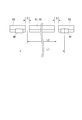
- FIG. 4 is a diagram showing an example of the traveling unit 20 and the connecting unit 30, (A) is a plan view, and (B) is a front view.
- the support member 31 of the connecting portion 30 is provided with a guide portion housing portion 31a.
- the guide portion 40 suppresses the positional displacement of the connecting portion 30 with respect to the lattice-shaped trajectory R, and thus suppresses the positional displacement of the main body portion 10 with respect to the lattice-shaped trajectory R.
- the guide parts 40 are provided on the respective connecting parts 30 arranged at the four corner parts 10a of the upper surface 17a of the main body part 10 (see FIGS. 1 and 2).
- the guide portion 40 moves along the first guide surface G1 and the first connection guide surface G3a in the first state in which the traveling wheels 21 travel on the first track R1.
- the guide portion 40 moves along the second guide surface G2 and the second connection guide surface G3b in the second state in which the traveling wheels 21 travel on the second track R2.
- the guide portion 40 may be in contact with the first guide surface G1 or the second guide surface G2 while the body portion 10 is running, or with respect to the first guide surface G1 or the second guide surface G2. It may be in a state with a gap.
- the guide part 40 has a guide roller 41 accommodated in the guide part accommodating part 31 a of the support member 31.
- the guide roller 41 is accommodated in the guide portion accommodating portion 31a, and is arranged such that the end portion on the ⁇ X side projects from the guide portion accommodating portion 31a.
- the guide roller 41 is supported by a roller shaft 41a so as to be rotatable around the Z axis.
- the roller shaft 41a is fixed inside the guide housing 31a and is arranged in parallel with the Z direction.
- the roller shaft 41a may be supported by an elastic member, for example.
- the guide roller 41 is movably and rotatably supported in the X direction, and the impact of the guide roller 41 hitting the first guide surface G1 or the like can be absorbed by the elastic member.
- the guide roller 41 is a driven roller that does not have a drive source that rotates the guide roller 41.
- a drive unit for rotating the guide roller 41 in accordance with the traveling direction of the main body unit 10 may be provided.
- the guide roller 41 is arranged at a height between the axle 21 a of the traveling wheel 21 and the main body 10.
- the first guide surface G1 and the second guide surface G2 are arranged at a height between the axle 21a of the traveling wheel 21 and the main body 10.
- the guide roller 41 is arranged in the connecting portion 30 at a position corresponding to the height of the first guide surface G1 and the second guide surface G2.
- the guide portion 40 changes the direction of the traveling wheel 21 by the direction changing mechanism 34, that is, the connecting portion 30 by the direction changing mechanism 34.
- the traveling wheels 21 are turned and the vehicle is turned about the turning axis AX2. Therefore, in the first state in which the traveling wheel 21 travels on the first track R1, the guide roller 41 is in a state of facing the first guide surface G1 and the first connection guide surface G3a, and the traveling wheel 21 is in the second track. In the second state of traveling on R2, the guide roller 41 is in a state of facing the second guide surface G2 and the second connection guide surface G3b.
- the guide roller 41 is rotated by using the direction changing mechanism 34 for switching the traveling state of the traveling wheel 21, it is not necessary to provide another mechanism for rotating the guide roller 41, and the main body 10 It prevents the configuration from becoming complicated.
- FIG. 5 is a plan view showing an example of the positional relationship between the guide roller 41 and the first track R1, the second track R2, the connecting track R3.
- FIG. 6 is a plan view showing an example of the guide portion 40 (guide roller 41) when the traveling wheels 21 are turned.
- a portion of the support member 31 projecting from the guide portion accommodating portion 31a is a side surface of the first track R1, a first guide surface G1 and a side surface of the second track R2. It is possible to contact the second guide surface G2, the first connection guide surface G3a, which is the side surface of the connection track R3, the second connection guide surface G3b, and the continuous surface G3c. 5 and 6, the guide portion accommodating portion 31a of the support member 31 is omitted.
- the guide roller 41 when the main body portion 10 travels in the first direction D1 (when the traveling wheels 21 are in the first state of rolling on the first track R1), the guide roller 41 has the first guide surface. It moves along G1 or the first connection guide surface G3a. In this first state, the guide roller 41 can contact the first guide surface G1 and the first connection guide surface G3a at the portion protruding from the guide portion housing portion 31a. Since the guide roller 41 can rotate when it comes into contact with the first guide surface G1 and the first connection guide surface G3a, the frictional resistance at the time of contact during traveling of the main body 10 is reduced, and the generation of particles is reduced. While restraining, the burden on the traveling drive unit 33 is restrained from increasing.
- the guide roller 41 hits the first guide surface G1 or the first connection guide surface G3a to move the main body 10 in the second direction D2.
- the positional deviation of is regulated. That is, the main body portion 10 has a pair of guide rollers 41 in the second direction D2, and the guide rollers 41 contact the first guide surface G1 or the first connection guide surface G3a facing each other. Positional shifts in the +Y direction and the ⁇ Y direction are suppressed. Therefore, the displacement of the main body 10 in the second direction D2 is regulated not only while the main body 10 is traveling in the first direction D1 but also when the main body 10 is stopped on any of the lattice-shaped tracks R.
- the direction changing mechanism 34 turns the traveling wheels 21.
- the guide roller 41 also turns around the turning axis AX2 by turning the connecting portion 30 by the direction changing mechanism 34.
- the guide roller 41 moves from the first connection guide surface G3a to the second connection guide surface G3b via the continuous surface G3c.
- the guide roller 41 can be smoothly moved while rotating.
- the continuous surface G3c is formed in an arc shape in a plan view, the guide roller 41 can be moved more smoothly.
- the form of the continuous surface G3c is not limited to the illustrated form, and may be, for example, a curved surface other than an arcuate shape in plan view, or a plurality of flat surfaces may be connected to form a corner portion, which is not smooth. There may be no form.
- the continuous surface G3c may not be formed. That is, the first connection guide surface G3a and the second connection guide surface G3b may be separated from each other, such as in a separated form. In this case, when the guide roller 41 moves from the first connection guide surface G3a to the second connection guide surface G3b, or when it moves from the second connection guide surface G3b to the first connection guide surface G3a, the guide rollers 41 and Are temporarily out of contact.
- the main body portion 10 can travel the main body portion 10 along the second direction D2 (running wheel). 21 is in a second state in which it rolls on the second track R2).
- the guide roller 41 can contact the second guide surface G2 and the second connection guide surface G3b at the portion protruding from the guide portion housing portion 31a. Since the guide roller 41 can rotate when it comes into contact with the second guide surface G2 and the second connection guide surface G3b as in the above, the frictional resistance at the time of contact while the main body 10 is running is reduced. The load on the traveling drive unit 33 is suppressed from increasing.
- the guide roller 41 hits the second guide surface G2 or the second connection guide surface G3b to move the main body unit 10 in the first direction D1.
- the positional deviation of is regulated. That is, the main body 10 has a pair of guide rollers 41 in the first direction D1, and the guide rollers 41 contact the second guide surface G2 or the second connection guide surface G3b that face each other. Positional shifts in the +X direction and the ⁇ X direction are suppressed. Therefore, the displacement in the first direction D1 is regulated not only when the main body portion 10 travels in the second direction D2 but also when the main body portion 10 is stopped on any of the lattice-shaped tracks R.
- FIG. 7 is a side view showing an example of the positional relationship between the track R and the guide roller 41.
- the distance L1 between the two guide rollers 41 lined up in the running direction among the four guide rollers 41 is different from the distance L2 between the adjacent gaps D in the first direction D1 or the second direction D2. Is set. With this configuration, it is possible to prevent the two guide rollers 41 aligned in the traveling direction from being positioned in the gap D at the same time.
- the interval L1 between the guide rollers 41 is larger than the interval L2 between the gaps D, but the invention is not limited to this form, and the interval L1 between the guide rollers 41 is the interval L2 between the gaps D. May be smaller than.
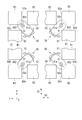
- FIG. 8 to 11 are diagrams showing an operation of changing the traveling direction of the overhead traveling vehicle 100 from the first direction D1 to the second direction D2.
- the main body 10 traveling in the first direction D1 in the first direction D1 (+X direction or ⁇ X direction) has one cell C (see FIG. 3) of the lattice-shaped track R. (Refer to FIG. 4) (the position where the four corner portions 10a approach the connection track R3). That is, the control unit 50 (see FIG. 1) stops the driving of the traveling drive unit 33 at the above position. At this time, all the four traveling wheels 21 are in contact with the connecting track R3. Further, the four guide rollers 41 are arranged at positions along the first connection guide surface G3a of the connection track R3.
- the control unit 50 drives the direction changing mechanism 34 to turn the coupling unit 30 and turns the traveling wheels 21 and the auxiliary wheels 22 arranged at the four corners 10a. It is swung in the ⁇ Z direction about the axis AX2. At this time, the diagonally running wheels 21 and the like turn in the same direction. For example, among the four traveling wheels 21, the upper left traveling wheel 21 and the like and the lower right traveling wheel 21 and the like turn clockwise in the figure. On the other hand, the traveling wheel 21 on the upper right and the traveling wheel 21 on the lower left in the figure turn counterclockwise. Note that such a turning operation may be performed at the same timing. For example, the upper left and lower right running wheels 21 and the like in the figure are first turned at the same time, and then the upper right and lower left running wheels are shown in the figure. You may turn at different timings, such as turning 21 and the like at the same time.
- the four guide rollers 41 are turned around the turning axis AX2 integrally with the connecting portion 30 and move along the continuous surface G3c. Therefore, the guide roller 41 turns at the same time as the running wheels 21 and the auxiliary wheels 22 turn, and the direction is switched. Since the guide roller 41 moves along the continuous surface G3c, the smooth movement of the guide roller 41 is ensured. It does not hinder the turning operation of the traveling wheels 21 and the like. Further, since the common direction changing mechanism 34 performs the turning of the traveling wheels 21 and the like and the turning of the guide roller 41, it is not necessary to separately provide a configuration for changing the direction of the guide roller 41, and the configuration of the main body unit 10 is not required. Avoids getting complicated.
- FIG. 10 is a diagram showing the guide roller 41 when the traveling wheels 21 are turning.
- the four guide rollers 41 provided in the connecting portion 30 change their directions in synchronization.
- each of the guide rollers 41 faces the connecting track R3 (continuous surface G3c), so that positional deviation is prevented.
- the guide roller 41 moves along the continuous surface G3c during the turning operation of the traveling wheels 21, it is possible to reliably prevent the displacement of the main body portion 10 during the turning operation of the traveling wheels 21.
- the control unit 50 stops the driving of the direction changing mechanism 34 after the traveling wheels 21 and the like each turn 90° in the ⁇ Z direction.
- the traveling drive unit 33 By driving the traveling drive unit 33 in this state, the overhead traveling vehicle 100 can travel in the second direction D2 (+Y direction or ⁇ Y direction).
- the four guide rollers 41 are arranged at positions along the second connection guide surface G3b of the connection track R3. Further, even when the traveling wheels 21 and the like turn, the main body portion 10 does not turn. Therefore, the orientation of the main body unit 10 is not changed whether the overhead traveling vehicle 100 travels in the first direction D1 or the second direction D2.
- the guide roller 41 of the guide portion 40 rotates integrally with the connecting portion 30, so that a configuration for changing the direction of the guide roller 41 is separately provided. Even if it does not exist, the direction of the guide roller 41 can be switched according to the direction change of the traveling wheel 21. As a result, the position shift of the main body unit 10 can be suppressed with a simple configuration while avoiding a complicated configuration of the overhead traveling vehicle 100.
- FIG. 8 to FIG. 11 show the case where the overhead traveling vehicle 100 changes the traveling direction from the first direction D1 to the second direction D2, the overhead traveling vehicle 100 changes from the second direction D2 to the first direction D1. The same applies when changing the traveling direction.
- first guide surface G1 and the second guide surface G2 have been described by taking the configuration in which the side surface of the first track R1 and the side surface of the second track R2 are respectively taken as an example. Not limited.
- FIG. 12 is a diagram showing another example of the track R, the traveling unit 20, and the connecting unit 30.
- guide plates Rp are attached to the side surfaces of the first track R1 and the second track R2 of the track R, and the surface of the guide plate Rp is set to the first guide surface G1 or the second guide surface G2. May be.
- the guide plate Rp is arranged so as to extend downward ( ⁇ Z side) from the side surfaces of the first track R1 and the second track R2. Therefore, the first guide surface G1 and the second guide surface G2 can be set below the first track R1 and the second track R2.
- a guide plate (not shown) extending downward from the side surface of the track is attached, and a first connection guide surface G3a, a second connection guide surface G3b, and a continuous surface G3c are formed.
- the guide roller 41 extends along a first guide surface G1 and a second guide surface G2 (including a first connection guide surface G3a, a second connection guide surface G3b, and a continuous surface G3c (not shown)).
- the position in the height direction is determined. Therefore, the guide roller 41 is arranged below the first track R1 and the second track R2.
- the first guide surface G1 and the like are not limited to being arranged below the first track R1 and the like.
- the guide plate Rp may be arranged above the first track R1 and the like. In this case, the guide plate Rp may be held on the first track R1 or the like via a support member or the like.
- the present invention is not limited to the above description, and various modifications can be made without departing from the scope of the present invention.
- the configuration in which the guide portion 40 is arranged on each of the four connecting portions 30 has been described as an example, but the configuration is not limited to this configuration.
- the guide portion 40 may be arranged in any one of the four connecting portions 30 to three.
- the guide portion 41 is described as an example in which the guide roller 41 that rotates around the axis of the roller shaft 41a is provided, but the present invention is not limited to this configuration.
- the guide portion 40 may have a non-rotating form such as a protrusion formed on the support member 31 of the connecting portion 30.
- the projecting portion may have a projecting portion formed in a spherical shape or a curved surface shape, and may have a shape that reduces the contact resistance with the first guide surface G1 and the like.
- the guide portion 40 is arranged with a predetermined gap with respect to each of the first guide surface G1, the second guide surface G2, the first connection guide surface G3a, the second connection guide surface G3b, and the continuous surface G3c.
- the configuration may be different.
- the lattice-shaped orbit R in which the first orbit R1 (first direction D1) and the second orbit R2 (second direction D2) are orthogonal to each other is described as an example, but this configuration is used.
- the trajectory R may have a form in which the first trajectory R1 and the second trajectory R2 are not orthogonal to each other.
- the first trajectory R1 and the second trajectory R2 are not limited to the form of a lattice trajectory R that intersects, and the trajectory R is, for example, the second trajectory R2 in a state of being bent from the end of the first trajectory R1. May be arranged.
Landscapes
- Engineering & Computer Science (AREA)
- Mechanical Engineering (AREA)
- Transportation (AREA)
- Warehouses Or Storage Devices (AREA)
- Platform Screen Doors And Railroad Systems (AREA)
- Solid State Image Pick-Up Elements (AREA)
- Carriers, Traveling Bodies, And Overhead Traveling Cranes (AREA)
- Vehicle Body Suspensions (AREA)
Abstract
Description
D1・・・第1方向
D2・・・第2方向
G1・・・第1ガイド面
G2・・・第2ガイド面
G3a・・・第1接続ガイド面
G3b・・・第2接続ガイド面
G3c・・・連続面
M・・・物品
L1、L2・・・間隔
R・・・格子状軌道(軌道)
R1・・・第1軌道
R2・・・第2軌道
R3・・・接続軌道
Rp・・・ガイド板
SYS・・・走行車システム
10・・・本体部
20・・・走行部
21・・・走行車輪
21a,22a・・・車軸
22・・・補助車輪
30・・・連結部
40・・・ガイド部
41・・・ガイドローラ
41a・・・ローラ軸
50・・・制御部
100・・・天井走行車
Claims (9)
- 第1方向に沿って延在する第1軌道と、前記第1方向とは異なる第2方向に沿って延在する第2軌道と、前記第1軌道に対して前記第1方向に隣り合うと共に前記第2軌道に対して前記第2方向に隣り合い、且つ前記第1軌道及び前記第2軌道それぞれとの間に間隙を隔てて配置された接続軌道と、を有する軌道と、
前記軌道に沿って走行する天井走行車と、を備える走行車システムであって、
前記軌道は、
前記第1軌道に沿って設けられた第1ガイド面と、
前記第2軌道に沿って設けられた第2ガイド面と、を有し、
前記天井走行車は、
前記第1軌道上、前記第2軌道上、及び前記接続軌道上を転動する走行車輪と、
前記軌道よりも下方に配置される本体部と、
前記走行車輪の車軸と前記本体部とを連結し、前記走行車輪が前記接続軌道上を転動する際に前記間隙を通過する連結部と、
前記本体部に対して前記連結部を旋回軸まわりに旋回させることにより、前記走行車輪が前記第1軌道上を転動する第1状態と、前記走行車輪が前記第2軌道上を転動する第2状態とを切り替える方向転換機構と、
前記連結部に設けられて、前記第1状態においては前記第1ガイド面に沿って移動し、前記第2状態においては前記第2ガイド面に沿って移動するガイド部と、を有する、走行車システム。 - 前記第1ガイド面は、前記第1軌道の側面であり、
前記第2ガイド面は、前記第2軌道の側面である、請求項1に記載の走行車システム。 - 前記ガイド部は、前記走行車輪の前記車軸と、前記本体部との間の高さに配置され、
前記第1ガイド面及び前記第2ガイド面は、前記走行車輪の前記車軸と、前記本体部との間の高さに配置される、請求項1又は請求項2に記載の走行車システム。 - 前記ガイド部は、前記第1ガイド面又は前記第2ガイド面に接触した際に転動可能なガイドローラである、請求項1から請求項3のいずれか一項に記載の走行車システム。
- 前記接続軌道は、前記第1ガイド面と同一の高さかつ同一方向に設けられる第1接続ガイド面と、前記第2ガイド面と同一の高さかつ同一方向に設けられる第2接続ガイド面と、を有する、請求項1から請求項4のいずれか一項に記載の走行車システム。
- 前記接続軌道は、前記第1接続ガイド面と前記第2接続ガイド面とを連続させる連続面を備える、請求項5に記載の走行車システム。
- 前記連続面は、前記第1接続ガイド面と前記第2接続ガイド面とを滑らかに接続する曲面である、請求項6に記載の走行車システム。
- 前記本体部は、前記連結部の前記旋回軸の軸方向から見て矩形状であり、4つのコーナー部のそれぞれに前記走行車輪、前記連結部、前記方向転換機構、及び前記ガイド部を有する、請求項1から請求項7のいずれか一項に記載の走行車システム。
- 前記天井走行車の走行方向に並ぶ2つの前記ガイド部の間隔は、前記第1方向又は前記第2方向において隣り合う2つの前記間隙の間隔と異なる、請求項8に記載の走行車システム。
Priority Applications (7)
| Application Number | Priority Date | Filing Date | Title |
|---|---|---|---|
| US17/297,508 US12103570B2 (en) | 2018-11-28 | 2019-10-23 | Traveling vehicle system |
| SG11202105601SA SG11202105601SA (en) | 2018-11-28 | 2019-10-23 | Traveling vehicle system |
| CN201980078570.3A CN113165671B (zh) | 2018-11-28 | 2019-10-23 | 行驶车系统 |
| KR1020217016113A KR102461617B1 (ko) | 2018-11-28 | 2019-10-23 | 주행차 시스템 |
| EP19888268.0A EP3888994B1 (en) | 2018-11-28 | 2019-10-23 | Travelling vehicle system |
| IL283506A IL283506B2 (en) | 2018-11-28 | 2019-10-23 | Traveling vehicle system |
| JP2020558181A JP7070704B2 (ja) | 2018-11-28 | 2019-10-23 | 走行車システム |
Applications Claiming Priority (2)
| Application Number | Priority Date | Filing Date | Title |
|---|---|---|---|
| JP2018-222552 | 2018-11-28 | ||
| JP2018222552 | 2018-11-28 |
Publications (1)
| Publication Number | Publication Date |
|---|---|
| WO2020110522A1 true WO2020110522A1 (ja) | 2020-06-04 |
Family
ID=70853448
Family Applications (1)
| Application Number | Title | Priority Date | Filing Date |
|---|---|---|---|
| PCT/JP2019/041503 Ceased WO2020110522A1 (ja) | 2018-11-28 | 2019-10-23 | 走行車システム |
Country Status (9)
| Country | Link |
|---|---|
| US (1) | US12103570B2 (ja) |
| EP (1) | EP3888994B1 (ja) |
| JP (1) | JP7070704B2 (ja) |
| KR (1) | KR102461617B1 (ja) |
| CN (1) | CN113165671B (ja) |
| IL (1) | IL283506B2 (ja) |
| SG (1) | SG11202105601SA (ja) |
| TW (1) | TWI810407B (ja) |
| WO (1) | WO2020110522A1 (ja) |
Cited By (2)
| Publication number | Priority date | Publication date | Assignee | Title |
|---|---|---|---|---|
| WO2022255062A1 (ja) | 2021-06-03 | 2022-12-08 | 村田機械株式会社 | 走行車システム、単位ユニット、及び格子状軌道 |
| CN116457262A (zh) * | 2020-11-13 | 2023-07-18 | 村田机械株式会社 | 行驶车系统 |
Families Citing this family (2)
| Publication number | Priority date | Publication date | Assignee | Title |
|---|---|---|---|---|
| TW202327964A (zh) * | 2021-11-05 | 2023-07-16 | 日商大福股份有限公司 | 物品搬送設備 |
| EP4556344A1 (en) | 2022-09-29 | 2025-05-21 | Murata Machinery, Ltd. | Overhead traveling vehicle system |
Citations (4)
| Publication number | Priority date | Publication date | Assignee | Title |
|---|---|---|---|---|
| JP2004189209A (ja) * | 2002-12-06 | 2004-07-08 | Samsung Electronics Co Ltd | オーバヘッドタイプの移送装置 |
| KR20150045157A (ko) * | 2013-10-18 | 2015-04-28 | 주식회사 에스에프에이 | 이송대차 시스템 |
| JP2016175506A (ja) * | 2015-03-19 | 2016-10-06 | 村田機械株式会社 | 搬送台車と搬送台車システム |
| WO2018037762A1 (ja) | 2016-08-26 | 2018-03-01 | 村田機械株式会社 | 有軌道台車システム、及び有軌道台車 |
Family Cites Families (12)
| Publication number | Priority date | Publication date | Assignee | Title |
|---|---|---|---|---|
| US6629502B2 (en) * | 2000-09-14 | 2003-10-07 | Daifuku Co., Ltd. | Conveyance system |
| JP5440870B2 (ja) * | 2010-08-19 | 2014-03-12 | 株式会社ダイフク | 物品搬送設備 |
| WO2012060291A1 (ja) * | 2010-11-04 | 2012-05-10 | ムラテックオートメーション株式会社 | 搬送システム及び搬送方法 |
| JP5527619B2 (ja) * | 2011-11-24 | 2014-06-18 | 株式会社ダイフク | 天井設置型の物品搬送設備 |
| JP5630661B2 (ja) * | 2011-12-19 | 2014-11-26 | 株式会社ダイフク | 天井設置型の物品搬送設備 |
| KR101521498B1 (ko) * | 2013-05-31 | 2015-05-19 | 주식회사 에스에프에이 | 반송대차 및 이를 이용하는 반송시스템 |
| WO2015005873A1 (en) * | 2013-07-12 | 2015-01-15 | Kavcic Samo | A vehicle |
| JP6168477B2 (ja) * | 2015-03-31 | 2017-07-26 | 村田機械株式会社 | 走行台車システム及び走行台車の走行方法 |
| JP6686834B2 (ja) * | 2016-10-12 | 2020-04-22 | 株式会社ダイフク | 物品搬送設備 |
| JP6677187B2 (ja) * | 2017-01-31 | 2020-04-08 | 株式会社ダイフク | 物品搬送設備 |
| JP6769336B2 (ja) | 2017-02-23 | 2020-10-14 | 株式会社ダイフク | 物品搬送車 |
| JP6946965B2 (ja) * | 2017-11-22 | 2021-10-13 | 村田機械株式会社 | 搬送システム |
-
2019
- 2019-10-23 JP JP2020558181A patent/JP7070704B2/ja active Active
- 2019-10-23 CN CN201980078570.3A patent/CN113165671B/zh active Active
- 2019-10-23 WO PCT/JP2019/041503 patent/WO2020110522A1/ja not_active Ceased
- 2019-10-23 SG SG11202105601SA patent/SG11202105601SA/en unknown
- 2019-10-23 KR KR1020217016113A patent/KR102461617B1/ko active Active
- 2019-10-23 US US17/297,508 patent/US12103570B2/en active Active
- 2019-10-23 EP EP19888268.0A patent/EP3888994B1/en active Active
- 2019-10-23 IL IL283506A patent/IL283506B2/en unknown
- 2019-11-20 TW TW108142071A patent/TWI810407B/zh active
Patent Citations (4)
| Publication number | Priority date | Publication date | Assignee | Title |
|---|---|---|---|---|
| JP2004189209A (ja) * | 2002-12-06 | 2004-07-08 | Samsung Electronics Co Ltd | オーバヘッドタイプの移送装置 |
| KR20150045157A (ko) * | 2013-10-18 | 2015-04-28 | 주식회사 에스에프에이 | 이송대차 시스템 |
| JP2016175506A (ja) * | 2015-03-19 | 2016-10-06 | 村田機械株式会社 | 搬送台車と搬送台車システム |
| WO2018037762A1 (ja) | 2016-08-26 | 2018-03-01 | 村田機械株式会社 | 有軌道台車システム、及び有軌道台車 |
Cited By (6)
| Publication number | Priority date | Publication date | Assignee | Title |
|---|---|---|---|---|
| CN116457262A (zh) * | 2020-11-13 | 2023-07-18 | 村田机械株式会社 | 行驶车系统 |
| WO2022255062A1 (ja) | 2021-06-03 | 2022-12-08 | 村田機械株式会社 | 走行車システム、単位ユニット、及び格子状軌道 |
| CN117203113A (zh) * | 2021-06-03 | 2023-12-08 | 村田机械株式会社 | 行驶车系统、单位单元以及格子状轨道 |
| KR20230169269A (ko) | 2021-06-03 | 2023-12-15 | 무라다기카이가부시끼가이샤 | 주행차 시스템, 단위 유닛 및 격자 형상 궤도 |
| EP4349679A4 (en) * | 2021-06-03 | 2025-06-11 | Murata Machinery, Ltd. | MOVING VEHICLE SYSTEM, UNIT AND GRID-SHAPED TRACK |
| CN117203113B (zh) * | 2021-06-03 | 2026-02-27 | 村田机械株式会社 | 行驶车系统、单位单元以及格子状轨道 |
Also Published As
| Publication number | Publication date |
|---|---|
| KR20210080536A (ko) | 2021-06-30 |
| IL283506B2 (en) | 2024-09-01 |
| IL283506B1 (en) | 2024-05-01 |
| TW202028036A (zh) | 2020-08-01 |
| EP3888994A4 (en) | 2022-08-03 |
| JPWO2020110522A1 (ja) | 2021-11-11 |
| US20220032971A1 (en) | 2022-02-03 |
| SG11202105601SA (en) | 2021-06-29 |
| CN113165671B (zh) | 2024-02-02 |
| IL283506A (en) | 2021-07-29 |
| US12103570B2 (en) | 2024-10-01 |
| EP3888994B1 (en) | 2024-08-28 |
| EP3888994A1 (en) | 2021-10-06 |
| KR102461617B1 (ko) | 2022-11-01 |
| JP7070704B2 (ja) | 2022-05-18 |
| CN113165671A (zh) | 2021-07-23 |
| TWI810407B (zh) | 2023-08-01 |
Similar Documents
| Publication | Publication Date | Title |
|---|---|---|
| KR102501700B1 (ko) | 천장 반송차 및 천장 반송차 시스템 | |
| WO2020110522A1 (ja) | 走行車システム | |
| JPWO2018037762A1 (ja) | 有軌道台車システム、及び有軌道台車 | |
| KR102557691B1 (ko) | 천장 주행차 시스템 | |
| JP2019093875A (ja) | 走行台車 | |
| JP7040636B2 (ja) | 走行車システム | |
| EP4227184A1 (en) | Overhead storage system | |
| US12272582B2 (en) | Overhead conveyance system | |
| JP7414153B2 (ja) | 走行車システム | |
| TW201943638A (zh) | 搬送裝置 | |
| JP7517605B2 (ja) | 走行車システム、単位ユニット、及び格子状軌道 | |
| WO2026088517A1 (ja) | 走行車システム | |
| TW202417352A (zh) | 高架行走車系統 |
Legal Events
| Date | Code | Title | Description |
|---|---|---|---|
| 121 | Ep: the epo has been informed by wipo that ep was designated in this application |
Ref document number: 19888268 Country of ref document: EP Kind code of ref document: A1 |
|
| ENP | Entry into the national phase |
Ref document number: 2020558181 Country of ref document: JP Kind code of ref document: A Ref document number: 20217016113 Country of ref document: KR Kind code of ref document: A |
|
| WWE | Wipo information: entry into national phase |
Ref document number: 283506 Country of ref document: IL |
|
| NENP | Non-entry into the national phase |
Ref country code: DE |
|
| ENP | Entry into the national phase |
Ref document number: 2019888268 Country of ref document: EP Effective date: 20210628 |