WO2020100353A1 - 分析装置及び分析方法 - Google Patents
分析装置及び分析方法 Download PDFInfo
- Publication number
- WO2020100353A1 WO2020100353A1 PCT/JP2019/030475 JP2019030475W WO2020100353A1 WO 2020100353 A1 WO2020100353 A1 WO 2020100353A1 JP 2019030475 W JP2019030475 W JP 2019030475W WO 2020100353 A1 WO2020100353 A1 WO 2020100353A1
- Authority
- WO
- WIPO (PCT)
- Prior art keywords
- analysis
- link
- information
- unit
- vehicle
- Prior art date
- Legal status (The legal status is an assumption and is not a legal conclusion. Google has not performed a legal analysis and makes no representation as to the accuracy of the status listed.)
- Ceased
Links
Images




Classifications
-
- G—PHYSICS
- G08—SIGNALLING
- G08G—TRAFFIC CONTROL SYSTEMS
- G08G1/00—Traffic control systems for road vehicles
- G08G1/01—Detecting movement of traffic to be counted or controlled
- G08G1/0104—Measuring and analyzing of parameters relative to traffic conditions
- G08G1/0108—Measuring and analyzing of parameters relative to traffic conditions based on the source of data
- G08G1/0112—Measuring and analyzing of parameters relative to traffic conditions based on the source of data from the vehicle, e.g. floating car data [FCD]
-
- G—PHYSICS
- G08—SIGNALLING
- G08G—TRAFFIC CONTROL SYSTEMS
- G08G1/00—Traffic control systems for road vehicles
- G08G1/01—Detecting movement of traffic to be counted or controlled
- G08G1/0104—Measuring and analyzing of parameters relative to traffic conditions
-
- G—PHYSICS
- G08—SIGNALLING
- G08G—TRAFFIC CONTROL SYSTEMS
- G08G1/00—Traffic control systems for road vehicles
- G08G1/01—Detecting movement of traffic to be counted or controlled
- G08G1/0104—Measuring and analyzing of parameters relative to traffic conditions
- G08G1/0125—Traffic data processing
- G08G1/0133—Traffic data processing for classifying traffic situation
-
- G—PHYSICS
- G08—SIGNALLING
- G08G—TRAFFIC CONTROL SYSTEMS
- G08G1/00—Traffic control systems for road vehicles
- G08G1/01—Detecting movement of traffic to be counted or controlled
- G08G1/0104—Measuring and analyzing of parameters relative to traffic conditions
- G08G1/0137—Measuring and analyzing of parameters relative to traffic conditions for specific applications
- G08G1/0145—Measuring and analyzing of parameters relative to traffic conditions for specific applications for active traffic flow control
-
- G—PHYSICS
- G08—SIGNALLING
- G08G—TRAFFIC CONTROL SYSTEMS
- G08G1/00—Traffic control systems for road vehicles
- G08G1/07—Controlling traffic signals
- G08G1/08—Controlling traffic signals according to detected number or speed of vehicles
Definitions
- the present invention relates to an analysis device and an analysis method for analyzing a moving body.
- Patent Document 1 discloses a technique for analyzing a traffic jam situation at such an intersection.
- the in-vehicle device of the vehicle that has passed the intersection to be analyzed collects the position information collected within a predetermined section until the vehicle passes the intersection, and the link information of the links that have traveled after the intersection.
- the probe information for each direction including the identification information is created. From this direction-specific probe information, it is possible to grasp the traveling state for each exit direction from the intersection. Further, it is possible to determine whether or not a traffic jam is occurring based on the grasped traveling state.
- an object of the present invention is to provide an analysis device and an analysis method capable of performing more appropriate analysis based on information such as position information of a plurality of mobile bodies.
- An analysis device for example, an analysis device 30 described later
- An analysis device includes a reception unit (for example, 311 described below) that receives a transition of position information of a plurality of moving bodies (for example, a vehicle 50 described below),
- a map information storage unit for example, a storage unit 32 to be described later
- a link designation unit that receives designation of the link information to be analyzed ( For example, the analysis condition designating unit 313) described below and the paths of each of the plurality of moving bodies after passing the link corresponding to the specified link information are determined, and the link transit time is totaled for each path, and the totalized result is obtained.
- a control unit for example, 313 described later
- identifies the cause of the traffic jam based on the separation of the representative values for each route based on the.
- the analysis is performed based on the transition of the position information of a plurality of moving bodies, it is possible to perform the analysis more appropriately as compared with the conventional method. Further, since it is based on a clear standard that the representative values are separated for each course, the analysis can be easily performed.
- the representative value is a link passage time or a link passage speed calculated based on a distance between the link passage time and a link corresponding to the link information. , Mode value, median value, or average value.
- analysis can be performed using values that are easy to calculate, such as the mode value, median value, and average value. Therefore, almost real-time analysis can be realized without requiring time for analysis.
- a control instruction unit (for example, a traffic instruction unit 314 described below) may be further provided.
- the analysis method of the present invention is an analysis method performed by a computer (for example, an analysis device 30 described below), and a receiving step of receiving transitions of position information of a plurality of mobile bodies (for example, a vehicle 50 described below).
- the route of each of the plurality of moving bodies after passing the link corresponding to the information is determined, the link transit time is aggregated for each route, and the cause of the traffic jam is determined based on the separation of the representative value for each route based on the aggregated result.
- a control step for specifying is performed by a computer (for example, an analysis device 30 described below), and a receiving step of receiving transitions of position information of a plurality of mobile bodies (for example, a vehicle 50 described below).
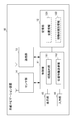
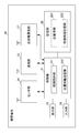
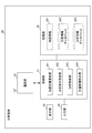
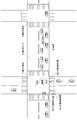
- FIG. 1 is a schematic view of an example of a road on which a vehicle travels according to an embodiment of the present invention. It is a figure which shows the example of the analysis information database in embodiment of this invention. It is a graph which shows an example of a totaling result in an embodiment of the present invention.
- FIG. 1 shows the overall configuration of the analysis system 1.
- the analysis system 1 is configured to include an in-vehicle navigation device 10, a mobile terminal 20, an analysis device 30, and a traffic control device 40. These devices and terminals are connected to each other via a communication network 60 so that they can communicate with each other. It should be noted that although information transmitted and received by each of these devices and terminals is also shown in the drawing, these information are merely examples. In this embodiment, information other than the illustrated information may be transmitted and received.
- the vehicle-mounted navigation device 10 is a device that performs navigation (route guidance) for a user who has boarded the vehicle 50a.
- the vehicle-mounted navigation device 10 provides route guidance from the current position to the destination based on the user's request.
- the in-vehicle navigation device 10 also has a function of positioning the positional information of the in-vehicle navigation device 10 (that is, the positional information of the vehicle 50a).
- the position information measured by the vehicle-mounted navigation device 10 is appropriately transmitted to the analysis device 30 together with the moving body identification information for identifying the vehicle 50a.
- the vehicle-mounted navigation device 10 can be realized by a car navigation device installed in a vehicle 50a that is a moving body or a PND (Portable Navigation Device) that is easily installed and portable in the vehicle 50a that is a moving body.
- the vehicle-mounted navigation device 10 can be realized by other vehicle-mounted electronic devices in which a predetermined application is installed.
- the mobile terminal 20 is a mobile terminal used by a user who gets in the vehicle 50b.
- the mobile terminal 20 has a function of positioning the position information of the mobile terminal 20 (that is, the position information of the vehicle 50b), similarly to the in-vehicle navigation device 10 described above.
- the position information measured by the mobile terminal 20 is appropriately transmitted to the analysis device 30 together with the moving body identification information for identifying the vehicle 50b, like the position information measured by the vehicle-mounted navigation device 10.
- the mobile terminal 20 can be realized by a smartphone, a mobile phone, a tablet terminal, a laptop computer, or any other portable electronic device in which a predetermined application is installed.
- vehicle 50 one set each of the vehicle-mounted navigation device 10 and the vehicle 50a and one set of the mobile terminal 20 and the vehicle 50b are shown, but the number of these sets is not particularly limited. Further, in the following description, when the vehicle 50a equipped with the vehicle-mounted navigation device 10 and the vehicle 50b on which the user of the mobile terminal 20 is aboard are not distinguished, the last alphabet is omitted, It is simply called "vehicle 50".
- the analysis device 30 is a device that performs a predetermined analysis based on the position information and the like of each vehicle 50, as processing unique to this embodiment.
- the analysis device 30 can be realized by incorporating an application for realizing the present embodiment into a server device or a personal computer, for example.
- the analysis device 30 acquires the position information of each vehicle 50 from the vehicle-mounted navigation device 10 and the mobile terminal 20.
- the analysis device 30 also creates a position information database that stores the transition of the position information of each vehicle 50 based on the acquired position information of each vehicle 50.
- the analysis device 30 stores, as the map information, the information of the roads through which each vehicle 50 can pass along with the link information including the intersection.
- the analysis device 30 receives the analysis condition input from the user who uses the analysis information to obtain the analysis information according to the condition desired by the user.
- the analysis condition is a condition including designation of link information corresponding to the intersection to be analyzed.
- the analysis device 30 performs an analysis according to the received analysis condition based on the information in the position information database and the map information. Specifically, the analysis device 30 determines the route of each of the plurality of vehicles 50 after passing through the link corresponding to the link information designated by the analysis condition. For example, as the route, it is determined whether each vehicle 50 has gone straight, turned left, or turned right at the intersection corresponding to the link information. Then, the analysis device 30 collects the link transit time for each route, and identifies the cause of the traffic congestion based on the separation of the representative values for each route based on the result of the counting. Thereby, the analysis device 30 can clarify whether the cause of the congestion is a right turn, a left turn, or a straight line.
- the analysis device 30 performs the analysis based on the transition of the position information of the plurality of vehicles 50, it is possible to perform the analysis more appropriately than the conventional one. Further, since it is based on a clear standard that the representative values are separated for each course, the analysis can be easily performed.
- the analysis device 30 may instruct the traffic control device 40 to change the traffic control so as to eliminate the identified cause of the traffic congestion based on the analysis result. As a result, it is possible to prompt the elimination of the cause of the traffic jam specified by the analysis. Further, the analysis device 30 may present the analysis result to the user. As a result, the user can obtain the analysis information according to the desired analysis condition input by the user.
- the user who uses the analysis device 30 may be, for example, a road administrator or an operator of a commercial facility (for example, a shopping center) near the road, or consult with the road administrator or the like. It may be a consultant. That is, the analysis device 30 can be used by various users for various purposes.
- the traffic control device 40 is a device that performs traffic control for a vehicle 50 moving on a road and a pedestrian crossing a pedestrian crossing.
- the traffic control device 40 is typically realized by a traffic signal. Then, the traffic control device 40 performs traffic control on the vehicle 50 and pedestrians by changing the lighting state or blinking state of the lights by the traffic control device 40 or by notifying a predetermined sound. Further, the traffic control device 40 can change the lighting state, the blinking state, or the like of the light based on the traffic control instruction from the analysis device 30. As a result, it is possible to promote the elimination of the cause of the traffic jam specified by the analysis by the analysis device 30.
- the vehicle 50 is a moving body on which the user of the in-vehicle navigation device 10 or the mobile terminal 20 rides.
- the vehicle 50 is realized by, for example, a four-wheeled vehicle, a motorcycle, a bicycle, or the like.
- the communication network 60 is realized by a network such as the Internet or a mobile phone network, or a network combining these.
- a LAN Local Area Network
- a LAN Local Area Network
- the vehicle-mounted navigation device 10 is supplied with power from the vehicle 50a, and is automatically started by turning on an ignition switch of the vehicle 50a (starting an engine) by a user who gets on the vehicle 50a. Then, the vehicle-mounted navigation device 10 operates until the user who gets on the vehicle 50a turns off the ignition switch of the vehicle 50a (stops the engine).
- the vehicle-mounted navigation device 10 includes a control unit 11, a storage unit 12, a communication unit 13, a sensor unit 14, a display unit 15, and an input unit 16.
- the control unit 11 is composed of an arithmetic processing unit such as a microprocessor, and controls each unit constituting the vehicle-mounted navigation device 10. Details of the control unit 11 will be described later.
- the storage unit 12 is composed of a semiconductor memory or the like, and has a control program called firmware or operating system, a program for performing route guidance processing, or a program for performing processing of transmitting position information to the analyzer 30. In addition to each program, various information such as map information is stored. In the figure, as the information stored in the storage unit 12, the position information 121 and the moving body identification information 122, which are information particularly related to the transmission processing of the position information, are illustrated.
- the position information 121 is the position information of the vehicle-mounted navigation device 10 (that is, the position information of the vehicle 50a) measured by the sensor unit 14 described later.
- the position information 121 includes not only the information indicating the position where the positioning is performed but also the time when the positioning is performed.
- the mobile body identification information 122 is information for identifying the in-vehicle navigation device 10.
- a manufacturing number uniquely assigned to the vehicle-mounted navigation device 10 can be used.
- the communication unit 13 in order for the communication unit 13 to connect to the communication network 60, which is a network such as a mobile phone network, the mobile number is assigned to the telephone number assigned to the SIM (Subscriber Identity Module) inserted in the communication unit 13. It can be used as the information 122.
- the VIN vehicle identification number
- uniquely assigned to the vehicle 50a or the number of the license plate can be used as the moving body identification information 122.
- the information stored in the storage unit 12 may be stored in the storage unit 12 in advance, or may be stored in a server device (not shown) connected to the communication network 60 as necessary. It may be configured to be downloaded as appropriate. Further, it may be appropriately modified according to the user's input or the like.
- the communication unit 13 has a DSP (Digital Signal Processor) and the like, and communicates in accordance with standards such as 3G (3rd Generation), LTE (Long Term Evolution), 4G (4th Generation), or Wi-Fi (registered trademark). Wireless communication is realized with another device (for example, the analysis device 30) via the network 60 via the communication network 60.
- the communication unit 13 is used, for example, by the position information transmission unit 112, which will be described later, to transmit the position information 121 and the moving body identification information 122 stored in the storage unit 12 to the analysis device 30.
- the data transmitted and received between the communication unit 13 and another device is not particularly limited, and information other than the position information 121 and the mobile body identification information 122 may be transmitted and received.
- the sensor unit 14 includes, for example, a GPS (Global Positioning System) sensor, a gyro sensor, an acceleration sensor, and the like.
- the sensor unit 14 has a function as a position detection unit that detects position information, receives a GPS satellite signal by a GPS sensor, and measures the position information (latitude and longitude) of the vehicle-mounted navigation device 10. Positioning by the sensor unit 14 is performed at predetermined time intervals (for example, 3 second intervals) as described above. Positioned position information is stored in the storage unit 12 as position information 121.
- the sensor unit 14 can further improve the positioning accuracy of the position information of the vehicle-mounted navigation device 10 based on the angular velocity measured by the gyro sensor or the acceleration sensor or the acceleration.
- AGPS Assisted Global Positioning System
- the sensor unit 14 uses AGPS (Assisted Global Positioning System) communication and uses the base station information acquired from the communication unit 13 to determine the position information of the vehicle-mounted navigation device 10. It is also possible to calculate
- the display unit 15 is composed of a display device such as a liquid crystal display or an organic electroluminescence panel.
- the display unit 15 displays an image in response to an instruction from the control unit 11.
- the information displayed by the display unit 15 is, for example, the current position of the vehicle-mounted navigation device 10, map information around the current position of the vehicle-mounted navigation device 10 read from the map information, destinations set by the user, other vehicle-mounted devices.
- the meeting information, route information, various user interfaces, etc. notified from the navigation device 10 are listed.
- the input unit 16 is composed of a physical switch called a numeric keypad, an input device (not shown) such as a touch panel provided on the display surface of the display unit 15, and the like.
- a signal based on an operation input from the input unit 16 for example, a user pressing a ten-key pad or a touch on the touch panel, it is possible to realize a user's selection operation or map enlargement / reduction operation. it can.
- a speaker, a microphone and the like may be provided.
- the speaker outputs a voice to the driver, and the microphone collects a voice or the like emitted by the driver. By doing so, it is possible to output information from the speaker by voice or input various selections and instructions by the driver, which are voice-input through the microphone, to the control unit 11 by the voice recognition technology.
- the control unit 11 is configured by a microprocessor having a CPU (Central Processing Unit), a RAM (Random access memory), a ROM (Read Only Memory), an I / O (Input / Output), and the like.
- the CPU executes each program read from the ROM or the storage unit 12, at the time of execution, reads information from the RAM, ROM, and storage unit 12, writes information to the RAM and storage unit 12, It exchanges signals with the communication unit 13, the sensor unit 14, the display unit 15, and the input unit 16.
- the processing in the present embodiment is realized by the cooperation of the hardware and the software (program).
- the control unit 11 includes a route guidance unit 111 and a position information transmission unit 112 as functional blocks.
- information on the congestion status of the road, information on the weather, and the like may be acquired through communication by the communication unit 13, and the acquired information may be used for route guidance processing. Since the route guidance processing to the destination is well known to those skilled in the art, further detailed description will be omitted. Further, since map information for performing route guidance processing is also well known to those skilled in the art, further detailed description and illustration will be omitted.
- the position information transmission unit 112 is a unit that transmits the position information 121 and the mobile unit identification information 122 stored in the storage unit 12 to the analysis device 30 by wireless communication using the communication unit 13.
- the transmission of the position information 121 and the moving body identification information 122 to the analysis device 30 by the position information transmission unit 112 is performed by the user riding in the vehicle 50a turning on the ignition switch of the vehicle 50a (starting the engine) and in-vehicle navigation device 10. Is automatically started until the ignition switch of the vehicle 50a is turned off (engine is stopped). For example, each time the sensor unit 14 performs positioning at a predetermined time interval (for example, every 3 seconds), transmission is performed in real time.
- a plurality of them (for example, the position information 121 and the moving body identification information 122 that are updated at intervals of 3 seconds during 3 minutes) are collected once. It may be transmitted to. That is, so-called burst transmission may be performed.
- the length of the predetermined time interval and whether to transmit in real time or burst transmission can be arbitrarily set according to the environment to which the present embodiment is applied and the like.
- the position information transmission unit 112 stores the position information 121 for specifying the movement route of the vehicle 50a positioned by the sensor unit 14 and the moving body identification information 122. , To the analyzer 30.
- the ignition switch is turned on (the engine is started), and the position specified by the position information 121 positioned immediately after the vehicle-mounted navigation device 10 is automatically started is set as the first vehicle position, that is, the starting position, and the analysis device 30 is set. Can be sent to. Further, the position specified by the position information 121 measured immediately before the ignition switch is turned off (engine stopped) can be transmitted to the analysis device 30 as the final vehicle position, that is, the parking position.
- the start information indicating the position information 121 indicating the departure position and the stop information indicating the position information 121 indicating the parking position are added to the position information 121 and then transmitted to the analyzer 30. You may do it.
- the flag indicating the start information may be set to 1 and transmitted, or the flag indicating the stop information may be set to 1 and transmitted.
- the position information 121 that is, the parking position measured immediately before the ignition switch is turned off (engine stopped), when the ignition switch is turned on (engine started) and the vehicle-mounted navigation device 10 is started again. May be sent to.
- the position information transmission unit 112 transmits in real time. It is better to switch to do. With this configuration, after the vehicle arrives at a certain facility and before the positional information 121 of the parking position is transmitted, the ignition switch is turned off (the engine is stopped), and the positional information 121 of the destination such as the facility is analyzed. It is possible to prevent a situation in which it is not transmitted to 30.
- the functional blocks included in the mobile terminal 20 will be described with reference to the block diagram of FIG.
- the above-described vehicle-mounted navigation device 10 is supplied with power from the vehicle 50a, but the mobile terminal 20 is supplied with power from a battery (not shown) included therein.
- the mobile terminal 20 may be supplied with power from a cigar socket or the like of the vehicle 50b in order to charge the battery.
- the mobile terminal 20 includes a control unit 21, a storage unit 22, a communication unit 23, a sensor unit 24, a display unit 25, an input unit 26, and a short-range communication unit 27.
- the control unit 21, the storage unit 22, the communication unit 23, the sensor unit 24, the display unit 25, and the input unit 26 have functions equivalent to the functional blocks of the same name included in the vehicle-mounted navigation device 10 described above.
- the functional blocks of the mobile terminal 20 will be explained by replacing the wording of "vehicle-mounted navigation apparatus 10" and the wording of "portable terminal 20" in the explanation of the vehicle-mounted navigation apparatus 10 described above, and thus repeated explanations will be repeated. Is omitted.
- the mobile terminal 20 differs from the vehicle-mounted navigation device 10 in that it includes the short-range communication unit 27, and so on, and the difference will be described below.
- the short-distance communication unit 27 performs non-contact short-distance communication conforming to standards such as NFC (Near Field Communication) and Bluetooth (registered trademark), or short-distance communication by wire via a USB (Universal Serial Bus) cable or the like. It is a part for.
- the vehicle 50b includes a short-range communication unit for communicating with the short-range communication unit 27.
- an ECU (Electronic Control Unit) of the vehicle 50b includes a short-range communication unit.
- the case where the mobile terminal 20 can communicate with the ECU by short-range communication is, that is, the case where the mobile terminal 20 is present inside the vehicle 50b.
- the position information measured by the sensor unit 24 of the mobile terminal 20 corresponds to the position information of the vehicle 50b.
- the mobile terminal 20 activates the position information transmission unit 212 while the short-range communication with the ECU is possible via the short-range communication unit 27. Then, the activated position information transmitting unit 212, similar to the position information transmitting unit 112 of the vehicle-mounted navigation device 10, the position information 221 for specifying the movement route of the vehicle 50b measured by the sensor unit 24, and the moving body identification. The information 222 is transmitted to the analysis device 30.
- the vehicle 50b and the portable terminal 20 are connected (paired) with each other.
- Positioned position information 221 and moving body identification information 222 are transmitted from the mobile terminal 20 to the analysis device 30.
- the position specified by the position information 121 positioned immediately after the pairing of the vehicle 50b and the mobile terminal 20 can be transmitted to the analysis device 30 as the first vehicle position, that is, the starting position.
- the position specified by the position information 121 positioned immediately before the cancellation can be transmitted to the analysis device 30 as the final vehicle position, that is, the parking position.
- real-time transmission or burst transmission may be performed, or burst transmission may be switched to real-time transmission if it is determined that the vehicle has arrived at the parking position, or departure position.
- the start information and stop information indicating the parking position may be added, and the parking position may be transmitted at the time of restarting, similarly to the position information transmitting unit 112.
- the position information of the vehicle 50b is transmitted to the analysis device 30 as the position information 121 instead of the position information of the sensor unit 24. You can In this case, the sensor unit 24 may be omitted from the mobile terminal 20.
- the analysis device 30 is configured to include a control unit 31, a storage unit 32, a communication unit 33, a display unit 34, and an input unit 35.
- the control unit 31 is composed of an arithmetic processing device such as a microprocessor, and controls each unit constituting the analysis device 30. Details of the control unit 31 will be described later.
- the storage unit 32 is composed of a semiconductor memory or the like, and stores various programs such as control programs called firmware and operating system, programs for performing information analysis processing, and various other information such as map information. To be done.
- map information 321 and position information database 322, which are information related to analysis processing of position information, are illustrated.
- the map information 321 includes information about features such as roads and facilities, road information, facility position information, parking lot information, and the like. Further, in addition to the map information 321, display map data for displaying backgrounds such as roads and road maps, position information of nodes (for example, road intersections, bending points, end points, etc.) and their type information, It includes position information and type information of links that are routes connecting nodes, road network data including link cost data relating to cost information (for example, distance, required time, etc.) of all links, and the like. That is, the map information 321 includes information on roads that each vehicle 50 can pass along with link information including intersections.
- road map information such as the position and shape of the road, the type of road and the position of traffic lights is stored.
- facility location information location information of each facility is stored as latitude and longitude information. Further, as the facility location information, the moving body identification information (facility ID) of the facility, name, facility type (and / or genre), telephone number, address, business hours, menu provided if the facility is a restaurant, product service Additional information such as facility information related to etc. may be included.
- parking lot information position information of the parking lot is stored as latitude and longitude information. When the parking lot is the parking lot of each facility, the facility and the parking lot are stored in association with each other.
- the map information 321 may be stored in the storage unit 32 in advance, or may be appropriately downloaded from a server device (not shown) connected to the communication network 60 as necessary. .. Further, it may be appropriately modified according to the user's input or the like.
- the position information database 322 is a database constructed based on the position information 121 and the position information 221, which are received from the vehicle-mounted navigation device 10 and the mobile terminal 20, respectively, and the mobile unit identification information 122 and the mobile unit identification information 222.
- the position information database 322 is constructed by the position information updating unit 311 described later. Details of the position information database 322 will be described later when the position information updating unit 311 is described.
- position information when the position information 121 and the position information 221 are described without distinction, the reference numerals are omitted and the position information is referred to as “position information”.
- the mobile unit identification information 122 and the mobile unit identification information 222 are described without distinction, the reference numerals will be omitted and will be referred to as “mobile unit identification information”.
- the communication unit 33 has a DSP or the like, and is in communication with another device via the communication network 60 via the communication network 60 in accordance with a communication standard such as 3G, LTE, 4G or Wi-Fi (registered trademark). To realize wireless communication.
- the communication unit 33 is used, for example, to receive the position information and the moving body identification information transmitted from the vehicle-mounted navigation device 10 and the mobile terminal 20, respectively.
- the data transmitted / received between the communication unit 33 and another device is not particularly limited, and information other than these information may be transmitted / received.
- the display unit 34 is composed of a display device such as a liquid crystal display or an organic electroluminescence panel.
- the display unit 34 displays an image in response to an instruction from the control unit 31. Examples of information displayed by the display unit 34 include an analysis result by an analysis control unit 313 described later, various information stored in the storage unit 32, various user interfaces, and the like.
- the input unit 35 is composed of an input interface (not shown) such as a keyboard and a mouse. By outputting a signal based on an operation input from the input unit 35, for example, a user's pressing of a keyboard or a moving operation of a mouse to the control unit 31, a user's selection operation or analysis condition input operation can be realized. it can.
- an input interface such as a keyboard and a mouse.
- the control unit 31 is composed of a microprocessor having a CPU, a RAM, a ROM, an I / O and the like.
- the CPU executes each program read from the ROM or the storage unit 32, reads the information from the RAM, the ROM, and the storage unit 32 at the time of execution, and writes the information to the RAM and the storage unit 32. It exchanges signals with the communication unit 33, the display unit 34, and the input unit 35.
- the processing in the present embodiment is realized by the cooperation of the hardware and the software (program).
- the control unit 31 includes a position information update unit 311, an analysis condition designation unit 312, an analysis control unit 313, and a traffic control instruction unit 314 as functional blocks.
- the position information updating unit 311 is a part that builds the position information database 322 and updates the position information database 322 as appropriate. An example of the data structure of the position information database 322 will be described with reference to FIG.
- the position information database 322 includes “moving body identification information” received from each of the vehicle-mounted navigation device 10 and the mobile terminal 20. Further, the position information database 322 includes “moving date and time” and “movement transition information” specified by the position information updating unit 311 based on the “position information” received from each of the vehicle-mounted navigation device 10 and the mobile terminal 20. Then, the location information updating unit 311 constructs and updates the location information database 322 by storing each of these pieces of information in the corresponding field in the location information database 322.
- the “moving body identification information” in the location information database 322 is information for identifying the vehicle-mounted navigation device 10 or the mobile terminal 20 which is the transmission source of the location information as described above. That is, it is information for identifying the vehicle 50 corresponding to the vehicle-mounted navigation device 10 or the mobile terminal 20.
- “Movement date and time” in the position information database 322 is information indicating the date and time when the vehicle 50 corresponding to the moving body identification information has moved.
- the date and time corresponding to this one movement is stored in the position information database 322 as the movement date and time.
- “Movement transition information” in the position information database 322 is information indicating a movement transition specified based on all the position information that is received during one movement and that changes in a time discrete manner.
- the position information updating unit 311 can specify the movement transition of the vehicle 50 by connecting the position information that discretely changes with time along the positioning time. That is, the movement transition information is information indicating the movement route and the movement speed of the vehicle 50.
- the position information updating unit 311 performs map matching that compares the position information with the map information 321 to identify the travel route. You can However, when the position information has high accuracy, it is not always necessary to perform map matching.
- the position information updating unit 311 is based on the received position information and moving body identification information each time the transmission of the position information and moving body identification information from one of the vehicle-mounted navigation devices 10 or the mobile terminals 20 is once started and then ended.
- the position information database 322 is updated by storing the above-mentioned information in a new field. It should be noted that the position information database 322 may be appropriately modified according to the input of the user of the analyzer 30.
- the analysis condition designation unit 312 is a part that receives analysis conditions. As described above, the analysis condition is a condition that the user inputs to obtain desired analysis information.
- the analysis condition designation unit 312 generates a user interface for receiving the input of the analysis condition from the user, and displays the generated user interface on the display unit 34 realized by the display. The user refers to this user interface and inputs the analysis conditions using the input unit 35 which is input by an input interface such as a keyboard or a mouse.
- the analysis condition is, for example, a condition including designation of link information corresponding to an intersection to be analyzed.
- FIG. 6 is a schematic view of an example of a road on which the vehicle 50 travels.
- the traffic control device 40a is arranged to perform traffic control for the driver of the vehicle 50.
- the traffic control device 40b and the traffic control device 40c are arranged to perform traffic control for a pedestrian walking on a pedestrian crossing.
- the traffic control device 40 is arranged corresponding to another traveling direction or another pedestrian crossing, but is not shown in FIG.
- the user when the user has a desire to “analyze the traffic jam situation of the Ath intersection 71 in the traveling direction from the Bth intersection 72 to the Ath intersection 71”, the user inputs.
- the traveling direction of the AB link 81 connecting the Bth intersection 72 and the Ath intersection 71 from the Bth intersection 72 to the Ath intersection 71 is designated as an analysis condition.
- the analysis condition designating section 312 receives this input as an analysis condition.
- the analysis conditions may include other conditions such as a time period for performing the analysis (for example, every 15 minutes). Further, the analysis condition designating section 312 outputs the accepted analysis conditions to the analysis control section 313.
- the analysis control unit 313 is a unit that generates the analysis information according to the analysis condition input from the analysis condition designation unit 312, based on the map information 321 and each information stored in the position information database 322. In order to generate the analysis information, the analysis control unit 313 first specifies, based on the map information 321, a link to be an analysis target specified by the analysis condition input from the analysis condition specifying unit 312. For example, in the case of the above-described example of the analysis conditions, the analysis control unit 313 specifies the traveling direction of the AB link 81 from the Bth intersection 72 to the Ath intersection 71 as an analysis target.
- the analysis control unit 313 identifies the vehicle 50 that has passed the link to be analyzed, based on the movement transition of the vehicle 50 identified by the movement information included in the position information database 322. For example, in the case of the above-described example of the analysis conditions, the analysis control unit 313 identifies the vehicle 50 that has passed the traveling direction of the AB link 81 from the Bth intersection 72 to the Ath intersection 71 as the analysis target vehicle 50. To do.
- the analysis control unit 313 determines the route of each vehicle 50 to be analyzed based on the movement transition of the vehicle 50. For example, the analysis control unit 313 determines, as the route, whether each vehicle 50 has gone straight, left turn, or right turn at the intersection (here, the Ath intersection 71) corresponding to the link information.
- the analysis control unit 313 also totals the link transit time for each route based on the movement transition of the vehicle 50. For example, the link passage time (here, the passage time of the AB-link 81 in this case) of each vehicle 50 that has traveled straight, left, or right is summed up. The link transit time can be calculated based on the time when the vehicle 50 enters the link and the time when the vehicle 50 leaves the link.
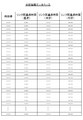
- the analysis control unit 313 stores the totalization result in the storage unit 32 as the analysis information database 323. An example of the data structure of the analysis information database 323 will be described with reference to FIG.
- the analysis information database 323 includes the “time zone” that is the target of aggregation.
- the analysis information database 323 includes a total of “inter-link passage time” for each of the straight, left-turn, and right-turn paths identified by the analysis control unit 313 based on the movement transition of the vehicle 50. Then, the analysis control unit 313 stores and stores each of these pieces of information in the corresponding field in the analysis information database 323, thereby constructing and updating the analysis information database 323.
- the analysis control unit 313 receives a plurality of link information as analysis conditions, the analysis control unit 313 builds and updates the analysis information database 323 for each of the plurality of links corresponding to the plurality of link information.
- the analysis control unit 313 identifies the cause of the traffic congestion based on the separation of the representative values for each route based on the aggregation result.
- the link passage speed of each vehicle 50 is calculated based on the aggregated link passage time and the link distance (here, the distance of the AB-link 81). Further, the mode of the link passing speed in each route is set as a representative value, and the cause of the traffic jam is specified based on the separation of the mode of the link passing speed.
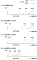
- FIG. 8 is a graph showing an example of the counting result.
- FIG. 8 shows four specific examples from FIG. 8 (A) to FIG. 8 (D).
- a graph is shown in which the link passing speed of each vehicle 50 is plotted in each of the straight, left, and right turns.
- the vertical axis corresponds to the number of vehicles and the horizontal axis corresponds to the link passing speed.
- a graph plotting the link passing speed of each vehicle 50 having a straight path is a "solid line”
- a graph plotting a link passing speed of each vehicle 50 having a left turn is a "dashed line”
- a graph plotting the link passing speed of each vehicle 50 having a right turn is shown by "dashed line”.
- FIG. 8 is a schematic one for simplifying the description, and does not show the actual link passing speed itself.
- the mode of the link passage speed (that is, the peak portion where the number of vehicles in the graph is the maximum) of a straight path, a left turn, and a right turn is equal to or higher than a predetermined speed. It has an appropriate link passage speed.
- the analysis control unit 313 analyzes that there is no traffic jam in each route and the traffic is smooth.
- the predetermined speed may be determined in advance, or may be appropriately modified based on the statistics of the link passing speed in the link in order to take the characteristics of the link into consideration.
- the link passage speed becomes slower in the order of straight path, turn left, turn right, and in consideration of this tendency, set the predetermined speed to a different speed for each path. You may.
- a part of the link passage speeds at the mode of the link passage speeds of the straight path, the left turn, and the right turn (here, the path is a right turn link) The passing speed) is less than the predetermined speed.
- the analysis control unit 313 calculates the separation of the mode values of the link passage speeds for the straight path, the left turn for the path, and the right turn for the path. In this example, as compared with the mode value where the path is straight and the mode value where the path is left turn, the mode values where the path is right turn are separated. In this case, the analysis control unit 313 analyzes that there is no traffic congestion when the route is a straight line and the route is a left turn, and the traffic is good. On the other hand, we analyze that the route is congested for a right turn. That is, it is analyzed that the cause of the traffic congestion is a right turn.
- the passing speed) is less than the predetermined speed.
- the analysis control unit 313 calculates the separation of the mode values of the link passage speeds for the straight path, the left turn for the path, and the right turn for the path. In this example, as compared with the mode value where the route is straight and the mode value where the route is right turn, the mode values where the route is left turn are separated.
- the analysis control unit 313 analyzes that there is no traffic congestion when the route is a straight line and the route is a right turn, and the traffic is good. On the other hand, we analyze that the route is congested for left turns. That is, it is analyzed that the cause of the traffic congestion is a left turn.
- a part of the link passing speeds in the mode of the link passing speeds of the straight path, the left turn, and the right turn (here, the path is a left turn link, respectively).
- the passing speed and the link speed for turning right) are less than the predetermined speed.
- the analysis control unit 313 calculates the separation of the mode values of the link passage speeds for the straight path, the left turn for the path, and the right turn for the path.
- the modal values of the paths are not widely separated. In this case, therefore, the analysis control unit 313 analyzes that all routes are crowded. In other words, we analyze that the cause of traffic congestion can be in all paths.
- the analysis control unit 313 outputs the analysis result to the traffic control instruction unit 314.
- the analysis control unit 313 displays the analysis result and various kinds of information stored in the storage unit 32 on the display unit 34 according to the user's operation or the like, and can communicate via the communication unit 33. Or to a device (not shown).
- the traffic control instruction unit 314 is a unit that transmits a traffic control instruction to the traffic control device 40 based on the analysis result by the analysis control unit 313. For example, as shown in FIG. 8A, the traffic control instructing unit 314 determines which of the traffic control devices 40 when the traffic is analyzed as being smooth without traffic congestion in each route. Do not issue traffic control instructions to Accordingly, the traffic control device 40 executes the traffic control by switching the state of the lights at the preset timing.
- the traffic control instructing unit 314 indicates, for example, when the right turn is in a traffic jam, indicating that the vehicle 50 can proceed in the right turn (e.g., a green light).
- a traffic control instruction is issued to the traffic control device 40 (here, the traffic control device 40a) so as to lengthen the time of the lighting state or the dot state of the arrow corresponding to the right turn.
- the traffic control device 40 here, the traffic control device 40a
- the traffic control instruction unit 314 indicates a state in which a pedestrian can proceed on a pedestrian crossing on the left turn side when a traffic jam occurs at the left turn ( For example, a traffic control instruction is issued to the traffic control device 40 (here, the traffic control device 40b or the traffic control device 40c) so as to shorten the time of the red traffic light. As a result, so-called pedestrian separation can be performed, and the congestion in the left turn, which is a cause of traffic congestion, can be eliminated.
- the traffic control instruction unit 314 indicates the time of a state in which the vehicle 50 can proceed when turning right, for example, when congestion occurs in all the routes.
- the traffic control device 40 is instructed to increase the length. If the vehicle 50 that makes a right turn and the vehicle 50 that makes a straight turn or makes a left turn is congested due to the influence of the vehicle 50 making a right turn, the congestion can be eliminated by this.
- a traffic control instruction is issued to the traffic control device 40 so as to shorten the time during which the pedestrian is allowed to proceed on the pedestrian crossing on the left turn side. If the vehicle 50 that makes a left turn and the vehicle 50 that makes a straight turn or makes a right turn is congested due to the influence of the vehicle 50 that makes a left turn, this can prompt the elimination of the congestion.
- the analysis device 30 can clarify whether the cause of the traffic congestion is a right turn, a left turn, or a straight line. In this way, the analysis device 30 performs the analysis based on the transition of the position information of the plurality of vehicles 50, so that the analysis can be performed more appropriately than in the past. Further, since it is based on a clear standard that the representative values are separated for each course, the analysis can be easily performed. Further, the analysis can be performed not only by an absolute standard called a predetermined standard (for example, a predetermined speed) but also by a relative standard called separation between the paths. As a result, even if the average passing speed is greatly different for each link, it is possible to relatively analyze the route according to each link.
- a predetermined standard for example, a predetermined speed
- the analysis device 30 may present the analysis result to the user.
- the user can obtain the analysis information according to the desired analysis condition input by the user. Then, the user, for example, if the analysis result indicates that there is congestion in the right turn, lengthens the existing right turn lane, or if the existing right turn lane does not exist, newly creates the right turn lane. It will be possible to take basic measures to eliminate traffic congestion, such as installing.
- the traffic control device 40 includes a control unit 41, a storage unit 42, a communication unit 43, and an output unit 44.
- the control unit 41 is composed of an arithmetic processing unit such as a microprocessor, and controls each unit constituting the traffic control device 40. Details of the control unit 41 will be described later.
- the storage unit 42 is composed of a semiconductor memory or the like, and stores control programs called firmware and operating system.
- a traffic control instruction 421 which is information regarding traffic control, is illustrated.
- the traffic control instruction 421 is information corresponding to the traffic control instruction received from the analysis device 30.
- the traffic control instruction 421 includes the content of traffic control executed by the traffic control execution unit 411, which will be described later, and an instruction of execution timing.
- an instruction is included that the so-called blue signal is lit for the first length, the second length is blinked, and then the so-called red signal is lit for the third length, which is repeated.
- the communication unit 43 has a DSP or the like, and is in communication with another device via the communication network 60 via the communication network 60 in accordance with a communication standard such as 4G, LTE, 4G or Wi-Fi (registered trademark). To realize wireless communication.
- the communication unit 43 is used, for example, to receive a traffic control instruction from the analysis device 30.
- the data transmitted / received between the communication unit 43 and another device is not particularly limited, and information other than these information may be transmitted / received.
- the output unit 44 is a part that outputs to execute traffic control for a vehicle 50 moving on a road or a pedestrian crossing a pedestrian crossing. For example, the output unit 44 outputs such that the lighting state or blinking state of the lamp is changed or a predetermined sound is notified.
- the control unit 41 includes a traffic control execution unit 411 as a functional block.
- the traffic control execution unit 411 is a unit that executes traffic control by controlling the output from the output unit 44.
- the traffic control execution unit 411 controls the output by the output unit 44 according to preset execution content and execution timing, thereby performing traffic control. Run.
- the traffic control execution unit 411 receives the traffic control instruction from the analysis device 30, and when the traffic control instruction 421 is stored, the execution content designated by the traffic control instruction 421 and the execution Traffic control is executed by controlling the output from the output unit 44 at the timing.
- traffic control is executed based on the analysis result of the analysis device 30, and it is possible to promote the elimination of traffic congestion.
- FIG. 10 is a flowchart showing an operation performed by the position information updating unit 311 exclusively at the time of collecting position information and updating the position information database 322.
- FIG. 11 is a flowchart showing an operation at the time of the analysis processing, which is exclusively performed by the analysis condition designating unit 312, the analysis control unit 313 and the traffic control instruction unit 314.
- the position information transmitter 112 determines whether or not to start the transmission of the position information (step S11).
- the transmission is started when the ignition switch of the vehicle 50a is turned on.
- the ignition switch remains off (No in step S11)
- the position information transmitter 112 does not start the transmission.
- the process proceeds to step S12.
- step S12 the sensor unit 14 acquires the position information by measuring the position of the vehicle-mounted navigation device 10 (step S12).
- the position information transmission unit 112 acquires the position information from the sensor unit 14 and transmits the acquired position information to the analysis device 30 in real time or in burst at a predetermined cycle (step S13).
- the position information transmitting unit 112 determines whether or not to end the position information transmission (step S14). As described above, the transmission ends when the ignition switch of the vehicle 50a is turned off. When the ignition switch of the vehicle 50a remains on (No in step S14), the positioning in step S12 and the transmission in step S13 are repeated.
- step S14 when the ignition switch of the vehicle 50a is turned off (Yes in step S14), the process proceeds to step S15.
- step S15 the position information updating unit 311 of the analysis device 30 updates the position information database 322 based on the position information transmitted by repeating steps S12 and S13 (step S15).
- step S15 the position information updating unit 311 of the analysis device 30 updates the position information database 322 based on the position information transmitted by repeating steps S12 and S13 (step S15).
- the position information transmitting unit 112 is replaced with the position information transmitting unit 211
- the sensor unit 14 is replaced with the sensor unit 24, and the criterion that becomes Yes in step S11 is “ignition switch or the like”.
- the start switch of the vehicle 50b is turned on and the vehicle 50b and the mobile terminal 20 are paired "
- the reference that becomes Yes in step S14 is" the start switch of the vehicle 50b such as an ignition switch is turned off and the vehicle 50b is turned off.
- the pairing of the mobile terminal 20 is released ”. Therefore, redundant description will be omitted.
- the analysis condition designation unit 312 receives the analysis condition from the user via the input unit 35 (step S21).
- the analysis condition designation unit 312 outputs the received analysis condition to the analysis control unit 313.
- the analysis control unit 313 determines the route of each vehicle 50 based on the analysis conditions and the map information 321 (step S22).
- the analysis control unit 313 updates the analysis information database 323 based on the determination result in step S21 and the position information of each vehicle 50 received from the vehicle-mounted navigation device 10 or the mobile terminal 20 stored in 322 ( Step S23).
- the analysis control unit 313 determines whether or not a predetermined time designated by the analysis condition in Step S21 (or set in advance) has elapsed after starting Step S22 and Step S23 (Step S24). .. For example, when the predetermined time designated by the analysis condition (or set in advance) is 15 minutes, it is determined whether 15 minutes have passed since the start of steps S22 and S23. If the predetermined time has elapsed (Yes in step S24), the process proceeds to step S25. On the other hand, when the predetermined time has not elapsed (No in step S24), the process returns to step S22, and the processes of steps S22 and S23 are repeated.
- the analysis control unit 313 analyzes the separation result of each route as described above with reference to FIG. 8 (step S25). The analysis control unit 313 identifies the cause of the traffic congestion based on the analysis result in step S25 (step S26).
- the traffic control instruction unit 314 creates a traffic control instruction that prompts the elimination of the cause of the traffic congestion based on the cause of the traffic congestion identified in step S26, and sends it to the traffic control device 40 (step S27).
- the traffic control device 40 that has received this traffic control instruction executes traffic control according to the instruction. As a result, it is possible to prompt the cancellation of the traffic jam. It should be noted that step S27 may be omitted if it is analyzed that no traffic congestion has occurred.
- the analysis control unit 313 determines whether or not to end this analysis process (step S28). For example, the analysis control unit 313 determines to end this analysis process when the end condition designated (or set in advance) by the analysis condition in step S21 is satisfied.
- the end condition is, for example, that a predetermined time has elapsed since the start of this analysis process, that a new analysis condition has been received, or that there has been no congestion for a predetermined time continuously.
- the end condition is satisfied (Yes in step S28)
- this analysis process ends.
- the ending condition is not satisfied (No in step S28)
- the process returns to step S22 and the above-described process is repeated.
- the mode of the link passing speed in each route is set as the representative value, and the cause of the traffic congestion is identified based on the separation of the mode of the link passing speed.
- the representative value is not limited to this and may be another value in each route.
- the mode of the link transit time may be used as the representative value.
- the median value or the average value of the link passage speed or the link passage time may be used as the representative value.
- the cause of the traffic congestion may be specified based on the separation of any one of these representative values. This makes it possible to use a more appropriate value as the representative value according to the analysis target and the like.
- one link corresponding to the link information designated by the designated condition is analyzed.
- the analysis is not limited to this, and analysis may be performed on other links.
- the analysis is performed for the next link traveling straight ahead.
- the next link it can be analyzed that the cause of the traffic jam is the next link (that is, the straight line to the next link is the cause of the traffic jam).
- the next link it can be analyzed that the cause of the traffic congestion is that the vehicle 50 making a left turn or a right turn is congested by the following vehicle 50 making a straight line.
- the vehicle-mounted navigation device 10 and the mobile terminal 20 may be realized by another device that does not have a route guidance function. That is, the route guidance function by the vehicle-mounted navigation device 10 or the mobile terminal 20 is not an essential configuration.
- the analysis device 30 may be further provided with a route guidance function, and the analysis device 30 may perform route guidance by communicating with the vehicle-mounted navigation device 10 or the mobile terminal 20.
- the analysis device 30 is realized by one server device or the like, but a distributed processing system in which each function of the analysis device 30 is appropriately distributed to a plurality of server devices. May be Moreover, you may implement
- the traffic control device 40 may have not only the function of lighting as a traffic signal, but also other functions. For example, a function of directly transmitting information for traffic control may be provided to the vehicle-mounted navigation device 10 or the mobile terminal 20. That is, the functional configurations of FIGS. 2, 3, 4, and 8 are merely examples, and the functional configurations of the present embodiment are not limited. That is, it suffices if each device is provided with a function capable of executing a series of processing relating to the information analysis function of the present invention as a whole. It is not limited to the examples of FIG. 3, FIG. 4, and FIG.
- Each of the devices included in the above navigation system can be realized by hardware, software, or a combination thereof.
- the navigation method performed by cooperation of each device included in the above navigation system can also be realized by hardware, software, or a combination thereof.
- “realized by software” means realized by the computer reading and executing the program.
- Non-transitory computer readable media include various types of tangible storage media. Examples of non-transitory computer readable media are magnetic recording media (eg, flexible disk, magnetic tape, hard disk drive), magneto-optical recording media (eg, magneto-optical disk), CD-ROM (Read Only Memory), CD- R, CD-R / W, semiconductor memory (for example, mask ROM, PROM (Programmable ROM), EPROM (Erasable PROM), flash ROM, RAM (random access memory)) are included.
- the program may be supplied to the computer by various types of transitory computer readable media. Examples of transitory computer-readable media include electrical signals, optical signals, and electromagnetic waves.
- the transitory computer-readable medium can supply the program to the computer via a wired communication path such as an electric wire and an optical fiber, or a wireless communication path.
Landscapes
- Physics & Mathematics (AREA)
- General Physics & Mathematics (AREA)
- Chemical & Material Sciences (AREA)
- Analytical Chemistry (AREA)
- Navigation (AREA)
- Traffic Control Systems (AREA)
Abstract
複数の移動体の位置情報等の情報に基づいて、より適切に分析を行なう。分析装置30が、複数の車両50の位置情報の推移を受信する311と、前記複数の車両50が通行可能な道路を、交差点を含むリンク情報と共に記憶する記憶部32と、分析対象とする前記リンク情報の指定を受け付けるリンク指定部312と、前記指定された前記リンク情報に対応するリンク通過後の前記複数の車両50それぞれの進路を判別し、進路毎にリンク通過時間を集計し、集計結果に基づいた進路毎の代表値の離間に基づいて、渋滞の原因を特定する制御部313と、を備える。
Description
本発明は、移動体に関する分析を行う、分析装置及び分析方法に関する。
従来、自動車等が移動する道路での渋滞を抑制するために、渋滞状況を分析することが望まれている。この点、特に交差点では、右折時の対向車の混雑状況、左折時の歩行者の有無、さらに直進後の道路の混雑等の様々な原因で、右左折時や直進時の渋滞状況が刻々と変化する。そのため、交差点における渋滞状況の分析は特に困難である。
このような交差点における渋滞状況の分析をするための技術が特許文献1に開示されている。特許文献1に開示の技術では、分析対象の交差点を通過した車両の車載装置が、当該交差点を通過するまでの間に所定区間内で収集した位置情報と、当該交差点を通過後に走行したリンクの識別情報とを含んだ方向別プローブ情報を作成する。
この方向別プローブ情報により、交差点からの退出方向別の走行状態を把握することができる。また、この把握した走行状態に基づいて、渋滞が発生しているか否かを判定することができる。
この方向別プローブ情報により、交差点からの退出方向別の走行状態を把握することができる。また、この把握した走行状態に基づいて、渋滞が発生しているか否かを判定することができる。
しかしながら、上述した特許文献1に開示の技術では、方向別プロープ情報に対応する車両が速度低下した場合に、その原因が渋滞では無く、運転手の意図的な運転や車両故障であった場合であっても、渋滞が発生していると判定してしまうおそれがあった。その理由は、各方向別プロープ情報が渋滞状況を正確に反映しているという前提で、各退出方向について一台の車両の方向別プローブ情報に基づいて、渋滞が発生している否かを判定するからである。
そこで本発明は、複数の移動体の位置情報等の情報に基づいて、より適切に分析を行なうことが可能な、分析装置及び分析方法を提供することを目的とする。
(1)本発明の分析装置(例えば、後述の分析装置30)は、複数の移動体(例えば、後述の車両50)の位置情報の推移を受信する受信部(例えば、後述の311)と、前記複数の移動体が通行可能な道路を、交差点を含むリンク情報と共に記憶する地図情報記憶部(例えば、後述の記憶部32)と、分析対象とする前記リンク情報の指定を受け付けるリンク指定部(例えば、後述の分析条件指定部313)と、前記指定された前記リンク情報に対応するリンク通過後の前記複数の移動体それぞれの進路を判別し、進路毎にリンク通過時間を集計し、集計結果に基づいた進路毎の代表値の離間に基づいて、渋滞の原因を特定する制御部(例えば、後述の313)と、を備える。
上記(1)によれば、複数の移動体の位置情報の推移に基づいて分析を行なうので、従来に比して、より適切に分析を行なうことができる。また進路毎の代表値の離間という明確な基準に基づいているので、簡易に分析を行なうことができる。
(2)上記(1)に記載の分析装置を、前記代表値は、前記リンク通過時間、又は、前記リンク通過時間と前記リンク情報に対応するリンクの距離に基づいて算出されたリンク通過速度の、最頻値、中央値、及び平均値の何れかであるようにしてもよい。
上記(2)によれば、最頻値、中央値、及び平均値といった、算出が容易な値により、分析を行なうことができる。そのため、分析に時間を要することなく、ほぼリアルタイムな分析が実現できる。
(3)上記(1)又は上記(2)に記載の分析装置を、前記制御部で特定された渋滞の原因を解消するように外部の交通制御機器に対して制御を変更する指示を行なう交通制御指示部(例えば、後述の交通指示部314)を更に備えるようにしてもよい。
上記(3)によれば、交通制御機器(例えば、信号機)による制御を変更することから、分析により特定した渋滞の原因の解消を促すことができる。
(4)本発明の分析方法は、コンピュータ(例えば、後述の分析装置30)が行う分析方法であって、複数の移動体(例えば、後述の車両50)の位置情報の推移を受信する受信ステップと、前記複数の移動体が通行可能な道路を、交差点を含むリンク情報と共に記憶する地図情報記憶ステップと、分析対象とする前記リンク情報の指定を受け付けるリンク指定ステップと、前記指定された前記リンク情報に対応するリンク通過後の前記複数の移動体それぞれの進路を判別し、進路毎にリンク通過時間を集計し、集計結果に基づいた進路毎の代表値の離間に基づいて、渋滞の原因を特定する制御ステップと、を有する。
上記(4)の方法によれば、上記(1)の分析装置と同様の効果を奏する。
本発明によれば、複数の移動体の位置情報等の情報に基づいて、より適切に分析を行なうことができる。
以下、本発明の分析システムの好ましい一実施形態について、図を参照しながら詳細に説明する。
<分析システム1の全体構成>
本発明の好ましい一実施形態に係る分析システム1について説明する。図1に、分析システム1の全体構成を示す。
本発明の好ましい一実施形態に係る分析システム1について説明する。図1に、分析システム1の全体構成を示す。
図1に示すように、分析システム1は、車載ナビゲーション装置10と、携帯端末20と、分析装置30と、交通制御機器40と、を含んで構成される。これら各装置及び各端末は、通信網60を介して相互に通信可能に接続される。なお、図中では、これら各装置及び各端末にて送受信される情報についても図示しているが、これらの情報はあくまで一例である。本実施形態にて、図示をしている以外の情報が送受信されるようにしてもよい。
車載ナビゲーション装置10は、車両50aに乗車したユーザに対して、ナビゲーション(経路案内)を行う装置である。車載ナビゲーション装置10は、ユーザの要求に基づき、現在位置から目的地までの経路案内を行う。また、車載ナビゲーション装置10は、車載ナビゲーション装置10の位置情報(すなわち、車両50aの位置情報)を測位する機能も有する。車載ナビゲーション装置10が測位した位置情報は、車両50aを識別するための移動体識別情報と共に、分析装置30に対して適宜送信される。
車載ナビゲーション装置10は、移動体である車両50aに据え付けられたカーナビゲーション装置や、移動体である車両50aに簡易的に設置され可搬可能なPND(Portable Navigation Device)により実現することができる。また、これ以外にも、車載ナビゲーション装置10は、所定のアプリケーションがインストールされた、その他の車載可能な電子機器により実現することができる。
車載ナビゲーション装置10は、移動体である車両50aに据え付けられたカーナビゲーション装置や、移動体である車両50aに簡易的に設置され可搬可能なPND(Portable Navigation Device)により実現することができる。また、これ以外にも、車載ナビゲーション装置10は、所定のアプリケーションがインストールされた、その他の車載可能な電子機器により実現することができる。
携帯端末20は、車両50bに乗車したユーザが利用する携帯端末である。携帯端末20は、上述した車載ナビゲーション装置10と同様に、携帯端末20の位置情報(すなわち、車両50bの位置情報)を測位する機能を有する。携帯端末20が測位した位置情報は、車載ナビゲーション装置10が測位した位置情報と同様に、車両50bを識別するための移動体識別情報と共に、分析装置30に対して適宜送信される。
携帯端末20は、所定のアプリケーションがインストールされた、スマートフォン、携帯電話機、タブレット端末、ノートパソコン、その他の携帯可能な電子機器により実現することができる。
携帯端末20は、所定のアプリケーションがインストールされた、スマートフォン、携帯電話機、タブレット端末、ノートパソコン、その他の携帯可能な電子機器により実現することができる。
なお、図中では、車載ナビゲーション装置10と車両50aの組と、携帯端末20と車両50bの組をそれぞれ一組ずつ図示しているが、これらの組数に特に制限はない。また、以下の説明において、車載ナビゲーション装置10が搭載された車両50aや、携帯端末20を利用するユーザが乗車する車両50bを区別することなく説明する場合には、末尾のアルファベットを省略して、単に「車両50」と呼ぶ。
分析装置30は、本実施形態特有の処理として、各車両50の位置情報等に基づいた、所定の分析を行う装置である。分析装置30は、例えばサーバ装置やパーソナルコンピュータに、本実施形態を実現するためのアプリケーションを組み込むことにより実現することができる。
具体的に、分析装置30は、車載ナビゲーション装置10や携帯端末20から、各車両50の位置情報を取得する。また、分析装置30は、取得した各車両50の位置情報に基づいて、各車両50の位置情報の推移を記憶する位置情報データベースを作成する。また、分析装置30は、地図情報として、各車両50が通行可能な道路の情報を、交差点を含むリンク情報と共に記憶する。
更に、分析装置30は、分析情報を利用するユーザから、ユーザの所望の条件に沿った分析情報を得るために入力される分析条件を受け付ける。ここで、分析条件は、分析対象とする交差点に対応するリンク情報の指定等を含む条件である。
更に、分析装置30は、分析情報を利用するユーザから、ユーザの所望の条件に沿った分析情報を得るために入力される分析条件を受け付ける。ここで、分析条件は、分析対象とする交差点に対応するリンク情報の指定等を含む条件である。
そして、分析装置30は、位置情報データベース内の情報と、地図情報とに基づいて、受け付けた分析条件に応じた分析を行う。
具体的に、分析装置30は、分析条件にて指定されているリンク情報に対応するリンク通過後の、複数の車両50それぞれの進路を判別する。例えば、進路として、各車両50がリンク情報に対応する交差点において直進したのか、左折したのか、それとも右折したのかを判別する。そして、分析装置30は、進路毎にリンク通過時間を集計し、集計結果に基づいた進路毎の代表値の離間に基づいて、渋滞の原因を特定する。これにより、分析装置30は、渋滞の原因となっている理由が右折、左折、直進の何れであるのかを明確することができる。
具体的に、分析装置30は、分析条件にて指定されているリンク情報に対応するリンク通過後の、複数の車両50それぞれの進路を判別する。例えば、進路として、各車両50がリンク情報に対応する交差点において直進したのか、左折したのか、それとも右折したのかを判別する。そして、分析装置30は、進路毎にリンク通過時間を集計し、集計結果に基づいた進路毎の代表値の離間に基づいて、渋滞の原因を特定する。これにより、分析装置30は、渋滞の原因となっている理由が右折、左折、直進の何れであるのかを明確することができる。
このように、分析装置30は、複数の車両50の位置情報の推移に基づいて分析を行なうので、従来に比して、より適切に分析を行なうことができる。また進路毎の代表値の離間という明確な基準に基づいているので、簡易に分析を行なうことが可能となる。
また、分析装置30は、この分析結果に基づいて、特定された渋滞の原因を解消するように交通制御機器40に対して交通制御を変更する指示を行なうようにしてもよい。これにより、分析により特定した渋滞の原因の解消を促すことができる。
更に、分析装置30は、この分析結果を、ユーザに対して提示するようにしてもよい。これにより、ユーザは、自身が入力した所望の分析条件に沿った分析情報を得ることができる。
更に、分析装置30は、この分析結果を、ユーザに対して提示するようにしてもよい。これにより、ユーザは、自身が入力した所望の分析条件に沿った分析情報を得ることができる。
なお、分析装置30を利用するユーザは、例えば、道路管理者や、道路近傍の商業施設(例えば、ショッピングセンター)の運営者であってもよいし、これら道路管理者等に対してコンサルティングを行うコンサルタントであってもよい。つまり、分析装置30は、様々なユーザが様々な用途に利用することができる。
交通制御機器40は、道路を移動する車両50や、横断歩道を渡る歩行者に対する交通制御を行なう機器である。交通制御機器40は、典型的には交通信号機により実現される。そして、交通制御機器40は、交通制御機器40による灯火の点灯状態や点滅状態を変更したり、所定の音を報知したりすることにより、これら車両50や歩行者に対する交通制御を行なう。
また、交通制御機器40は、分析装置30の交通制御指示に基づいて、灯火の点灯状態や、点滅状態等を変更することができる。これにより、分析装置30による分析により特定した渋滞の原因の解消を促すことが実現される。
また、交通制御機器40は、分析装置30の交通制御指示に基づいて、灯火の点灯状態や、点滅状態等を変更することができる。これにより、分析装置30による分析により特定した渋滞の原因の解消を促すことが実現される。
車両50は、車載ナビゲーション装置10や携帯端末20のユーザが乗車する移動体である。車両50は、例えば、四輪自動車や自動二輪車や自転車等により実現される。
通信網60は、インターネットや携帯電話網といったネットワークや、これらを組み合わせたネットワークにより実現される。また、ネットワークの一部に、LAN(Local Area Network)が含まれていてもよい。
<車載ナビゲーション装置10が備える機能ブロック>
次に、車載ナビゲーション装置10が備える機能ブロックについて図2のブロック図を参照して説明をする。
ここで、車載ナビゲーション装置10は、車両50aから電源の供給を受けており、車両50aに乗車したユーザにより車両50aのイグニッションスイッチがオン(エンジンを起動)にされることによって自動起動する。そして、車載ナビゲーション装置10は、車両50aに乗車したユーザにより車両50aのイグニッションスイッチがオフ(エンジンを停止)にされるまで稼働する。
次に、車載ナビゲーション装置10が備える機能ブロックについて図2のブロック図を参照して説明をする。
ここで、車載ナビゲーション装置10は、車両50aから電源の供給を受けており、車両50aに乗車したユーザにより車両50aのイグニッションスイッチがオン(エンジンを起動)にされることによって自動起動する。そして、車載ナビゲーション装置10は、車両50aに乗車したユーザにより車両50aのイグニッションスイッチがオフ(エンジンを停止)にされるまで稼働する。
図2に示すように、車載ナビゲーション装置10は、制御部11と、記憶部12と、通信部13と、センサ部14と、表示部15と、入力部16とを含んで構成される。
制御部11は、マイクロプロセッサ等の演算処理装置から構成され、車載ナビゲーション装置10を構成する各部の制御を行う。制御部11の詳細については、後述する。
記憶部12は、半導体メモリ等で構成されており、ファームウェアやオペレーティングシステムと呼ばれる制御用のプログラムや、経路案内処理を行うためのプログラムや、分析装置30に対する位置情報の送信処理を行うためのプログラムといった各プログラム、更にその他、地図情報等の種々の情報が記憶される。図中には、記憶部12が記憶する情報として、位置情報の送信処理に特に関する情報である、位置情報121及び移動体識別情報122を図示する。
位置情報121は、後述のセンサ部14により測位された車載ナビゲーション装置10の位置情報(すなわち、車両50aの位置情報)である。位置情報121には、測位された位置を示す情報のみならず、測位を行った時刻も含まれるようにする。
また、移動体識別情報122は、車載ナビゲーション装置10を識別するための情報である。移動体識別情報122としては、例えば車載ナビゲーション装置10に一意に割り当てられた製造番号等を利用することができる。また、他にも、通信部13が携帯電話網等のネットワークである通信網60に接続するために、通信部13に挿入されたSIM(Subscriber Identity Module)に付与された電話番号を移動体識別情報122として利用することができる。また、他にも、車両50aに固有に付与されたVIN(車両識別番号)やナンバープレートの番号を移動体識別情報122として利用することができる。
また、移動体識別情報122は、車載ナビゲーション装置10を識別するための情報である。移動体識別情報122としては、例えば車載ナビゲーション装置10に一意に割り当てられた製造番号等を利用することができる。また、他にも、通信部13が携帯電話網等のネットワークである通信網60に接続するために、通信部13に挿入されたSIM(Subscriber Identity Module)に付与された電話番号を移動体識別情報122として利用することができる。また、他にも、車両50aに固有に付与されたVIN(車両識別番号)やナンバープレートの番号を移動体識別情報122として利用することができる。
これらの記憶部12に格納される各情報については、記憶部12に予め記憶しておく構成としてもよいし、通信網60に接続されたサーバ装置(図示を省略する。)等から必要に応じて適宜ダウンロードされる構成としてもよい。更に、ユーザの入力等に応じて適宜修正されてもよい。
通信部13は、DSP(Digital Signal Processor)等を有し、3G(3rd Generation)、LTE(Long Term Evolution)、4G(4th Generation)或いはWi-Fi(登録商標)といった規格に準拠して、通信網60を介して通信網60を介した他の装置(例えば、分析装置30)との間の無線通信を実現する。通信部13は、例えば、後述の位置情報送信部112が、記憶部12に格納されている位置情報121及び移動体識別情報122を、分析装置30に対して送信するために利用される。ただし、通信部13と他の装置との間で送受信されるデータに特に制限はなく、位置情報121及び移動体識別情報122以外の情報が送受信されるようにしてもよい。
センサ部14は、例えばGPS(Global Positioning System)センサ、ジャイロセンサ、加速度センサ等により構成される。センサ部14は、位置情報を検出する位置検出手段としての機能を備え、GPSセンサによりGPS衛星信号を受信し、車載ナビゲーション装置10の位置情報(緯度及び経度)を測位する。センサ部14による測位は、上述したように所定の時間間隔(例えば3秒間隔)で行われる。測位した位置情報は、位置情報121として記憶部12に格納される。
なお、センサ部14は、ジャイロセンサ、加速度センサにより測定される角速度や、加速度に基づいて車載ナビゲーション装置10の位置情報の測位精度を更に高めることも可能である。
また、センサ部14は、GPS通信が困難又は不可能となった場合に、AGPS(Assisted Global Positioning System)通信を利用し、通信部13から取得される基地局情報によって車載ナビゲーション装置10の位置情報を算出することも可能である。
また、センサ部14は、GPS通信が困難又は不可能となった場合に、AGPS(Assisted Global Positioning System)通信を利用し、通信部13から取得される基地局情報によって車載ナビゲーション装置10の位置情報を算出することも可能である。
表示部15は、液晶ディスプレイ、又は有機エレクトロルミネッセンスパネル等の表示デバイスにより構成される。表示部15は、制御部11からの指示を受けて画像を表示する。表示部15が表示する情報としては、例えば、車載ナビゲーション装置10の現在位置、地図情報から読み出された車載ナビゲーション装置10の現在位置周辺の地図情報、ユーザに設定された目的地、他の車載ナビゲーション装置10から通知された待ち合わせ情報、ルート情報、各種のユーザインタフェース等が挙げられる。
入力部16は、テンキーと呼ばれる物理スイッチや表示部15の表示面に重ねて設けられたタッチパネル等の入力装置(図示を省略する。)等で構成される。入力部16からの操作入力、例えばユーザによるテンキーの押下、タッチパネルのタッチに基づいた信号を制御部11に出力することで、ユーザによる選択操作や、地図の拡大縮小等の操作を実現することができる。
なお、この他、図示しないが、スピーカやマイク等を備えることもできる。スピーカは、運転者に対して音声出力を行い、マイクは、運転者によって発せられた音声等を集音する。
そうすることで、情報をスピーカから音声で出力したり、マイクを介して音声入力された運転者による各種の選択、指示を音声認識技術により、制御部11に入力したりすることもできる。
そうすることで、情報をスピーカから音声で出力したり、マイクを介して音声入力された運転者による各種の選択、指示を音声認識技術により、制御部11に入力したりすることもできる。
次に、制御部11の詳細について説明をする。制御部11はCPU(Central Processing Unit)、RAM(Random access memory)、ROM(Read Only Memory)、及びI/O(Input / output)等を有するマイクロプロセッサにより構成される。CPUは、ROM又は記憶部12から読み出した各プログラムを実行し、その実行の際にはRAM、ROM、及び記憶部12から情報を読み出し、RAM及び記憶部12に対して情報の書き込みを行い、通信部13、センサ部14、表示部15、及び入力部16と信号の授受を行う。そして、このようにして、ハードウェアとソフトウェア(プログラム)が協働することにより本実施形態における処理は実現される。
制御部11は、機能ブロックとして、経路案内部111及び位置情報送信部112を備える。
経路案内部111は、ユーザによって入力又は選択された施設等の目的地までの経路案内処理を行う部分である。
目的地までの経路案内処理は、一般的なカーナビゲーションシステムにおける経路案内処理と同等である。すなわち、経路案内部111は、記憶部12に記憶されている地図情報(図示を省略する。)に基づいて目的地までの地図を生成し、この地図上にセンサ部14により測位された車載ナビゲーション装置10の現在位置と目的地の位置と目的地までのルート情報とを重ね、これを表示部15に表示することにより経路案内を行うことができる。この場合に、更に、図示を省略したスピーカから経路案内用の音声を出力するようにしてもよい。また、道路の混雑状況の情報や天気の情報等を通信部13による通信により取得して、この取得した情報を経路案内処理に利用するようにしてもよい。
なお、目的地までの経路案内処理については、当業者によく知られているので、これ以上の詳細な説明は省略する。また、経路案内処理を行うための地図情報についても、当業者によく知られているので、これ以上の詳細な説明及び図示は省略する。
目的地までの経路案内処理は、一般的なカーナビゲーションシステムにおける経路案内処理と同等である。すなわち、経路案内部111は、記憶部12に記憶されている地図情報(図示を省略する。)に基づいて目的地までの地図を生成し、この地図上にセンサ部14により測位された車載ナビゲーション装置10の現在位置と目的地の位置と目的地までのルート情報とを重ね、これを表示部15に表示することにより経路案内を行うことができる。この場合に、更に、図示を省略したスピーカから経路案内用の音声を出力するようにしてもよい。また、道路の混雑状況の情報や天気の情報等を通信部13による通信により取得して、この取得した情報を経路案内処理に利用するようにしてもよい。
なお、目的地までの経路案内処理については、当業者によく知られているので、これ以上の詳細な説明は省略する。また、経路案内処理を行うための地図情報についても、当業者によく知られているので、これ以上の詳細な説明及び図示は省略する。
位置情報送信部112は、通信部13を利用した無線通信により、記憶部12に格納されている位置情報121及び移動体識別情報122を、分析装置30に対して送信する部分である。
位置情報送信部112による、分析装置30に対する位置情報121及び移動体識別情報122の送信は、車両50aに乗車したユーザにより車両50aのイグニッションスイッチがオン(エンジンを起動)にされ、車載ナビゲーション装置10が自動起動してから、車両50aのイグニッションスイッチがオフ(エンジンを停止)にされるまでの間、周期的に行われる。例えば、所定の時間間隔(例えば3秒間隔)でセンサ部14が測位を行う都度、リアルタイムに送信が行われる。また、リアルタイムに分析装置30に送信するのではなく、複数個まとめて(例えば3分間分の間に3秒間隔で更新された位置情報121と、移動体識別情報122とをまとめて)、一度に送信するようにしてもよい。すなわち、いわゆるバースト送信をするようにしてもよい。かかる、所定の時間間隔の長さや、リアルタイムに送信するか、それともバースト送信するかは、本実施形態を適用する環境等に応じて、任意に設定することができる。
位置情報送信部112による、分析装置30に対する位置情報121及び移動体識別情報122の送信は、車両50aに乗車したユーザにより車両50aのイグニッションスイッチがオン(エンジンを起動)にされ、車載ナビゲーション装置10が自動起動してから、車両50aのイグニッションスイッチがオフ(エンジンを停止)にされるまでの間、周期的に行われる。例えば、所定の時間間隔(例えば3秒間隔)でセンサ部14が測位を行う都度、リアルタイムに送信が行われる。また、リアルタイムに分析装置30に送信するのではなく、複数個まとめて(例えば3分間分の間に3秒間隔で更新された位置情報121と、移動体識別情報122とをまとめて)、一度に送信するようにしてもよい。すなわち、いわゆるバースト送信をするようにしてもよい。かかる、所定の時間間隔の長さや、リアルタイムに送信するか、それともバースト送信するかは、本実施形態を適用する環境等に応じて、任意に設定することができる。
このようにして、リアルタイム送信やバースト送信を行うことにより、位置情報送信部112は、センサ部14が測位した車両50aの移動経路を特定するための位置情報121と、移動体識別情報122とを、分析装置30に対して送信する。
この場合に、イグニッションスイッチがオン(エンジンを起動)にされ、車載ナビゲーション装置10が自動起動した直後に測位された位置情報121により特定される位置を最初の車両位置、すなわち出発位置として分析装置30に送信することができる。更に、イグニッションスイッチがオフ(エンジン停止)される直前に測位された位置情報121により特定される位置を最終の車両位置、すなわち駐車位置として分析装置30に送信することができる。
この場合、出発位置を表す位置情報121であることを示す起動情報や、駐車位置を表す位置情報121であることを示す停止情報を、位置情報121に追加してから、分析装置30に送信するようにしてもよい。例えば、起動情報であることを示すフラグを1にして送信したり、停止情報であることを示すフラグを1にして送信したりするとよい。なお、イグニッションスイッチがオフ(エンジン停止)される直前に測位された位置情報121(すなわち、駐車位置)については、イグニッションスイッチがオン(エンジンを起動)にされ、車載ナビゲーション装置10が再度起動した際に送信されてもよい。
また、バースト送信を行う場合であっても、経路案内部111により車両50aが目的地(例えば、或る施設)に到着したと判断された場合には、位置情報送信部112は、リアルタイムに送信を行うように切り替えるとよい。このようにすれば、或る施設に到着後、駐車位置の位置情報121が送信される前に、イグニッションスイッチがオフ(エンジン停止)されてしまい、施設等の目的地の位置情報121が分析装置30に対して送信されない、という事態を防止することができる。
<携帯端末20が備える機能ブロック>
次に、携帯端末20が備える機能ブロックについて図3のブロック図を参照して説明をする。
ここで、上述した車載ナビゲーション装置10は、車両50aから電源の供給を受けていたが、携帯端末20は自身が備えるバッテリ(図示を省略する。)から電源の供給を受ける。ただし、バッテリを充電するために携帯端末20が車両50bのシガーソケット等から電源の供給を受けるようにしてもよい。
次に、携帯端末20が備える機能ブロックについて図3のブロック図を参照して説明をする。
ここで、上述した車載ナビゲーション装置10は、車両50aから電源の供給を受けていたが、携帯端末20は自身が備えるバッテリ(図示を省略する。)から電源の供給を受ける。ただし、バッテリを充電するために携帯端末20が車両50bのシガーソケット等から電源の供給を受けるようにしてもよい。
図3に示すように、携帯端末20は、制御部21と、記憶部22と、通信部23と、センサ部24と、表示部25と、入力部26と、近距離通信部27とを含んで構成される。
ここで、制御部21と、記憶部22と、通信部23と、センサ部24と、表示部25と、入力部26は、上述した車載ナビゲーション装置10が含む同名の機能ブロックと同等の機能を有している。つまり、上述した車載ナビゲーション装置10の説明における「車載ナビゲーション装置10」の文言と「携帯端末20」の文言を置き換えることにより、携帯端末20の各機能ブロックの説明となるので、重複する再度の説明は省略する。
ここで、制御部21と、記憶部22と、通信部23と、センサ部24と、表示部25と、入力部26は、上述した車載ナビゲーション装置10が含む同名の機能ブロックと同等の機能を有している。つまり、上述した車載ナビゲーション装置10の説明における「車載ナビゲーション装置10」の文言と「携帯端末20」の文言を置き換えることにより、携帯端末20の各機能ブロックの説明となるので、重複する再度の説明は省略する。
一方で、携帯端末20は、近距離通信部27を含んでいる点等で、車載ナビゲーション装置10と相違するので、この相違点について、以下説明をする。
近距離通信部27は、NFC(Near Field Communication)やBluetooth(登録商標)といった規格に準拠した非接触の近距離通信、又はUSB(Universal Serial Bus)ケーブル等を介した有線による近距離通信を行うための部分である。
一方で、車両50bは、近距離通信部27と通信を行うための近距離通信部を備える。例えば車両50bのECU(Electronic Control Unit)が近距離通信部を備える。
そして、携帯端末20がECUと近距離通信により通信することができる場合とは、すなわち、携帯端末20が車両50bの車内に存在する場合である。この場合、携帯端末20のセンサ部24が測位する位置情報は、車両50bの位置情報に相当することになる。
近距離通信部27は、NFC(Near Field Communication)やBluetooth(登録商標)といった規格に準拠した非接触の近距離通信、又はUSB(Universal Serial Bus)ケーブル等を介した有線による近距離通信を行うための部分である。
一方で、車両50bは、近距離通信部27と通信を行うための近距離通信部を備える。例えば車両50bのECU(Electronic Control Unit)が近距離通信部を備える。
そして、携帯端末20がECUと近距離通信により通信することができる場合とは、すなわち、携帯端末20が車両50bの車内に存在する場合である。この場合、携帯端末20のセンサ部24が測位する位置情報は、車両50bの位置情報に相当することになる。
そこで、携帯端末20は、近距離通信部27を介してECUと近距離通信できる間は、位置情報送信部212を起動させる。そして、起動した位置情報送信部212が、車載ナビゲーション装置10の位置情報送信部112と同様にして、センサ部24が測位した車両50bの移動経路を特定するための位置情報221と、移動体識別情報222とを、分析装置30に対して送信する。
例えば、ユーザが携帯端末20を所持して車両50bに乗車し、イグニッションスイッチ等の車両50bの起動スイッチをオンにすると、車両50bと携帯端末20とが接続(ペアリング)され、携帯端末20で測位した位置情報221及び移動体識別情報222が携帯端末20から分析装置30に送信される。この場合、車両50bと携帯端末20とのペアリング直後に測位された位置情報121により特定される位置を最初の車両位置、すなわち出発位置として分析装置30に送信することができる。
更に、イグニッションスイッチ等の車両50bの起動スイッチがオフにされると、車両50bと携帯端末20とのペアリングが解除される。この場合、解除された直前に測位された位置情報121により特定される位置を最終の車両位置、すなわち駐車位置として分析装置30に送信することができる。
この場合に、リアルタイムで送信してもよく、バースト送信してもよい点や、駐車位置に到着したと判断された場合には、バースト送信をリアルタイムの送信に切り替えても良い点や、出発位置又は駐車位置であることを示す起動情報や停止情報を追加しても良い点や、再起動時に駐車位置を送信しても良い点も位置情報送信部112と同様である。
この場合に、リアルタイムで送信してもよく、バースト送信してもよい点や、駐車位置に到着したと判断された場合には、バースト送信をリアルタイムの送信に切り替えても良い点や、出発位置又は駐車位置であることを示す起動情報や停止情報を追加しても良い点や、再起動時に駐車位置を送信しても良い点も位置情報送信部112と同様である。
なお、車両50bが位置情報を測位する機能を有している場合には、センサ部24が測位する位置情報ではなく、車両50bが測位する位置情報を位置情報121として分析装置30に送信するようにしてもよい。この場合、携帯端末20から、センサ部24を省略するようにしてもよい。
<分析装置30が備える機能ブロック>
次に、分析装置30が備える機能ブロックについて図4のブロック図を参照して説明をする。
次に、分析装置30が備える機能ブロックについて図4のブロック図を参照して説明をする。
図4に示すように、分析装置30は、制御部31と、記憶部32と、通信部33と、表示部34と、入力部35とを含んで構成される。
制御部31は、マイクロプロセッサ等の演算処理装置から構成され、分析装置30を構成する各部の制御を行う。制御部31の詳細については、後述する。
記憶部32は、半導体メモリ等で構成されており、ファームウェアやオペレーティングシステムと呼ばれる制御用のプログラムや、情報分析処理を行うためのプログラムといった各プログラム、更にその他、地図情報等の種々の情報が記憶される。図中には、記憶部32が記憶する情報として、位置情報の分析処理に特に関する情報である、地図情報321、及び位置情報データベース322を図示する。
地図情報321には、道路や施設等の地物に関する情報、道路情報、施設位置情報、駐車場情報等の情報が含まれる。また、地図情報321には他にも、道路及び道路地図等の背景を表示するための表示用地図データ、ノード(例えば道路の交差点、屈曲点、端点等)の位置情報及びその種別情報、各ノード間を結ぶ経路であるリンクの位置情報及びその種別情報、全てのリンクのコスト情報(例えば距離、所要時間等)に関するリンクコストデータ等を含む道路ネットワークデータ等が含まれる。すなわち、地図情報321は、各車両50が通行可能な道路の情報を、交差点を含むリンク情報と共に含んでいる。
道路情報としては道路の位置及び形状や、道路の種別や信号機の位置等のいわゆる道路地図の情報が保存されている。
施設位置情報としては、各施設の位置情報が緯度経度の情報として保存されている。また、施設位置情報として、施設の移動体識別情報(施設ID)、名称、施設種別(及び/又はジャンル)、電話番号、住所、営業時間、施設が飲食店であれば提供するメニュー、商品役務等に関する施設情報、等の付帯的な情報が含まれていてもよい。
駐車場情報としては、駐車場の位置情報が緯度経度の情報として保存されている。駐車場が各施設の駐車場である場合には、施設と駐車場を紐付けて保存される。
施設位置情報としては、各施設の位置情報が緯度経度の情報として保存されている。また、施設位置情報として、施設の移動体識別情報(施設ID)、名称、施設種別(及び/又はジャンル)、電話番号、住所、営業時間、施設が飲食店であれば提供するメニュー、商品役務等に関する施設情報、等の付帯的な情報が含まれていてもよい。
駐車場情報としては、駐車場の位置情報が緯度経度の情報として保存されている。駐車場が各施設の駐車場である場合には、施設と駐車場を紐付けて保存される。
地図情報321は、記憶部32に予め記憶しておく構成としてもよいし、通信網60に接続されたサーバ装置(図示を省略する。)等から必要に応じて適宜ダウンロードされる構成としてもよい。更に、ユーザの入力等に応じて適宜修正されてもよい。
位置情報データベース322は、車載ナビゲーション装置10及び携帯端末20のそれぞれから受信した位置情報121及び位置情報221、並びに、移動体識別情報122及び移動体識別情報222に基づいて構築されたデータベースである。位置情報データベース322は、後述の位置情報更新部311により構築される。位置情報データベース322の詳細については、位置情報更新部311の説明の際に後述する。なお、以下の説明では、位置情報121及び位置情報221を区別することなく説明する際は、符号を省略して「位置情報」と呼ぶ。また、同様に移動体識別情報122及び移動体識別情報222を区別することなく説明する際は、符号を省略して「移動体識別情報」と呼ぶ。
通信部33は、DSP等を有し、3G、LTE、4G或いはWi-Fi(登録商標)といった通信規格に準拠して、通信網60を介して通信網60を介した他の装置との間の無線通信を実現する。通信部33は、例えば、車載ナビゲーション装置10及び携帯端末20のそれぞれから送信される位置情報及び移動体識別情報を受信するために利用される。
ただし、通信部33と他の装置との間で送受信されるデータに特に制限はなく、これらの情報以外の情報が送受信されるようにしてもよい。
ただし、通信部33と他の装置との間で送受信されるデータに特に制限はなく、これらの情報以外の情報が送受信されるようにしてもよい。
表示部34は、液晶ディスプレイ、又は有機エレクトロルミネッセンスパネル等の表示デバイスにより構成される。表示部34は、制御部31からの指示を受けて画像を表示する。表示部34が表示する情報としては、例えば、後述の分析制御部313による分析結果や、記憶部32に記憶されている各種情報、各種のユーザインタフェース等が挙げられる。
入力部35は、キーボードやマウスといった入力インターフェース(図示を省略する。)等で構成される。入力部35からの操作入力、例えばユーザによるキーボードの押下、マウスによる移動操作等に基づいた信号を制御部31に出力することで、ユーザによる選択操作や、分析条件の入力操作を実現することができる。
次に、制御部31の詳細について説明をする。制御部31はCPU、RAM、ROM、及びI/O等を有するマイクロプロセッサにより構成される。CPUは、ROM又は記憶部32から読み出した各プログラムを実行し、その実行の際にはRAM、ROM、及び記憶部32から情報を読み出し、RAM及び記憶部32に対して情報の書き込みを行い、通信部33、表示部34、及び入力部35と信号の授受を行う。そして、このようにして、ハードウェアとソフトウェア(プログラム)が協働することにより本実施形態における処理は実現される。
制御部31は、機能ブロックとして、位置情報更新部311、分析条件指定部312、分析制御部313、及び交通制御指示部314を含む。
位置情報更新部311は、位置情報データベース322を構築すると共に、位置情報データベース322を適宜更新する部分である。位置情報データベース322のデータ構造の一例について図5を参照して説明する。
図5に示すように、位置情報データベース322は、車載ナビゲーション装置10及び携帯端末20のそれぞれから受信した「移動体識別情報」を含む。また、位置情報データベース322は、車載ナビゲーション装置10及び携帯端末20のそれぞれから受信した「位置情報」に基づいて位置情報更新部311が特定した、「移動日時」及び「移動推移情報」を含む。
そして、位置情報更新部311は、これらの情報それぞれを、位置情報データベース322内の対応するフィールドに格納することにより、位置情報データベース322を構築及び更新する。
そして、位置情報更新部311は、これらの情報それぞれを、位置情報データベース322内の対応するフィールドに格納することにより、位置情報データベース322を構築及び更新する。
位置情報データベース322内の「移動体識別情報」は、上述したように位置情報の送信元である車載ナビゲーション装置10や携帯端末20を識別するための情報である。すなわち、車載ナビゲーション装置10や携帯端末20に対応する車両50を識別する情報である。
位置情報データベース322内の「移動日時」は、移動体識別情報に対応する車両50が移動した日時を示す情報である。本実施形態では、例えば、何れかの車載ナビゲーション装置10又は携帯端末20から位置情報の送信が一度開始されて終了するまでを1つの移動として扱う。そして、この1つの移動に対応する日時を移動日時として位置情報データベース322内に格納する。
位置情報データベース322内の「移動推移情報」は、1つの移動の間に受信した、時間離散的に変化する位置情報の全てに基づいて特定される移動推移を示す情報である。位置情報更新部311は、この時間離散的に変化する位置情報を測位時刻に沿ってつなぐことにより、車両50の移動推移を特定することができる。すなわち、移動推移情報は、車両50の移動経路及び移動速度を示す情報である。
なお、本実施形態を実装した環境において、位置情報の精度が低いような場合には、位置情報更新部311は、地図情報321と位置情報を照らし合わせるマップマッチングを行って移動経路を特定するようにしてもよい。ただし、位置情報の精度が高いような場合には、必ずしもマップマッチングを行う必要はない。
なお、本実施形態を実装した環境において、位置情報の精度が低いような場合には、位置情報更新部311は、地図情報321と位置情報を照らし合わせるマップマッチングを行って移動経路を特定するようにしてもよい。ただし、位置情報の精度が高いような場合には、必ずしもマップマッチングを行う必要はない。
位置情報更新部311は、何れかの車載ナビゲーション装置10又は携帯端末20から位置情報及び移動体識別情報の送信が一度開始されてから終了する都度、受信した位置情報及び移動体識別情報に基づいて新たなフィールドに、上述した各情報を格納することにより位置情報データベース322を更新する。
なお、分析装置30のユーザの入力等に応じて、位置情報データベース322を適宜修正するようにしてもよい。
なお、分析装置30のユーザの入力等に応じて、位置情報データベース322を適宜修正するようにしてもよい。
分析条件指定部312は、分析条件を受け付ける部分である。上述したように、分析条件は、ユーザが所望の分析情報を得るために入力する条件である。分析条件指定部312は、ユーザから分析条件の入力を受け付けるためのユーザインタフェースを生成し、生成したユーザインタフェースを、ディスプレイにより実現される表示部34に対して表示させる。ユーザは、このユーザインタフェースを参照して、キーボードやマウス等の入力インターフェースにより入力される入力部35にて、分析条件を入力する。
ここで、分析条件は、例えば、分析対象とする交差点に対応するリンク情報の指定等を含む条件である。
この点について、車両50が走行する道路の一例を俯瞰した模式図である図6を参照して説明をする。図6には、道路の構成要素として、第A交差点71と、第B交差点72と、これら2つの交差点をつなぐ第ABリンク81と、これら道路に対応して配置された交通制御機器40と、これら道路を走行する車両50と、を示す。ここで、交通制御機器40aは、車両50の運転手に対して交通制御を行なうために配置される。また、交通制御機器40bと、交通制御機器40cは、横断歩道を歩行する歩行者に対して交通制御を行なうために配置される。なお、交通制御機器40は、他の進行方向や、他の横断歩道にも対応して配置されるが、図6では図示を省略する。
この点について、車両50が走行する道路の一例を俯瞰した模式図である図6を参照して説明をする。図6には、道路の構成要素として、第A交差点71と、第B交差点72と、これら2つの交差点をつなぐ第ABリンク81と、これら道路に対応して配置された交通制御機器40と、これら道路を走行する車両50と、を示す。ここで、交通制御機器40aは、車両50の運転手に対して交通制御を行なうために配置される。また、交通制御機器40bと、交通制御機器40cは、横断歩道を歩行する歩行者に対して交通制御を行なうために配置される。なお、交通制御機器40は、他の進行方向や、他の横断歩道にも対応して配置されるが、図6では図示を省略する。
このような具体例において、ユーザが「第B交差点72から第A交差点71への走行方向における、第A交差点71の渋滞状況を解析したい。」という希望を持っている場合に、ユーザは、入力部35を用いて、「第B交差点72と第A交差点71をつなぐ第ABリンク81の、第B交差点72から第A交差点71への走行方向」を分析条件として指定する。分析条件指定部312は、この入力を分析条件として、受け付ける。なお、分析条件には、他にも、例えば、分析を行なう時間的な周期(例えば、15分毎)等の他の条件が含まれていてもよい。
また、分析条件指定部312は、受け付けた分析条件を、分析制御部313に対して出力する。
また、分析条件指定部312は、受け付けた分析条件を、分析制御部313に対して出力する。
分析制御部313は、地図情報321と、位置情報データベース322に格納されている各情報とに基づいて、分析条件指定部312から入力された分析条件に応じた分析情報を生成する部分である。
分析情報の生成のために、分析制御部313は、まず、地図情報321に基づいて、分析条件指定部312から入力された分析条件にて指定された分析対象とするリンクを特定する。例えば、上述した分析条件の例であれば、分析制御部313は、第ABリンク81の、第B交差点72から第A交差点71への走行方向を分析対象として特定する。
分析情報の生成のために、分析制御部313は、まず、地図情報321に基づいて、分析条件指定部312から入力された分析条件にて指定された分析対象とするリンクを特定する。例えば、上述した分析条件の例であれば、分析制御部313は、第ABリンク81の、第B交差点72から第A交差点71への走行方向を分析対象として特定する。
次に、分析制御部313は、位置情報データベース322に含まれる移動情報により特定される車両50の移動推移に基づいて、分析対象とするリンクを通過した車両50を特定する。例えば、上述した分析条件の例であれば、分析制御部313は、第ABリンク81の、第B交差点72から第A交差点71への走行方向を通過した車両50を分析対象の車両50として特定する。
次に、分析制御部313は、車両50の移動推移に基づいて、分析対象の車両50それぞれの進路を判別する。例えば、分析制御部313は、進路として、各車両50がリンク情報に対応する交差点(ここでは、第A交差点71)において直進したのか、左折したのか、それとも右折したのかを判別する。
また、分析制御部313は、車両50の移動推移に基づいて、進路毎にリンク通過時間を集計する。例えば、直進、左折、右折、のそれぞれの進路をとった各車両50のリンク通過時間(ここでは、第ABリンク81の通過時間)を集計する。リンク通過時間は、車両50が、リンクに進入した時刻と、リンクから退去した時刻とに基づいて算出することができる。分析制御部313は、この集計結果を、分析情報データベース323として記憶部32に記憶させる。分析情報データベース323のデータ構造の一例について図7を参照して説明する。
図7に示すように、分析情報データベース323は、集計の対象とした「時間帯」含む。また、分析情報データベース323は、車両50の移動推移に基づいて分析制御部313が特定した、直進、左折、及び右折の各進路それぞれについての「リンク間通過時間」の集計を含む。
そして、分析制御部313は、これらの情報それぞれを、分析情報データベース323内の対応するフィールドに格納することにより、分析情報データベース323を構築及び更新する。なお、分析制御部313は、分析条件として複数のリンク情報を受け付けた場合は、この複数のリンク情報に対応する複数のリンクそれぞれについて、分析情報データベース323を構築及び更新する。
そして、分析制御部313は、これらの情報それぞれを、分析情報データベース323内の対応するフィールドに格納することにより、分析情報データベース323を構築及び更新する。なお、分析制御部313は、分析条件として複数のリンク情報を受け付けた場合は、この複数のリンク情報に対応する複数のリンクそれぞれについて、分析情報データベース323を構築及び更新する。
そして、分析制御部313は、集計結果に基づいた進路毎の代表値の離間に基づいて、渋滞の原因を特定する。本実施形態では、一例として、集計したリンク通過時間と、リンクの距離(ここでは、第ABリンク81の距離)に基づいて、各車両50のリンク通過速度を算出する。また、各進路における、このリンク通過速度の最頻値を代表値とし、このリンク通過速度の最頻値の離間に基づいて、渋滞の原因を特定する。
この点について、集計結果の一例を示すグラフである図8を参照して説明をする。図8には、図8(A)から図8(D)までの4つの具体例を示す。各具体例では、直進、左折、右折、の各進路における、各車両50のリンク通過速度をプロットしたグラフを示す。図示しているように、各グラフにおいて、縦軸は台数に対応し、横軸はリンク通過速度に対応する。また、進路が直線の各車両50のリンク通過速度をプロットしたグラフを「実線」、進路が左折の各車両50のリンク通過速度をプロットしたグラフを「破線」、進路が右折の各車両50のリンク通過速度をプロットしたグラフを「一点鎖線」にて図示する。
なお、図8における具体例は、説明を簡略とするために模式化したものであり、実際のリンク通過速度そのものを示したものではない。
なお、図8における具体例は、説明を簡略とするために模式化したものであり、実際のリンク通過速度そのものを示したものではない。
まず、図8(A)を参照すると、進路が直線、進路が左折、及び進路が右折の、それぞれリンク通過速度の最頻値(すなわち、グラフにおける台数が最大のピーク部分)について所定の速度以上の適切なリンク通過速度となっている。この場合、分析制御部313は、各進路において渋滞が発生しておらず、交通が順調であると分析する。なお、所定の速度は、予め決定しておいてもよいし、そのリンクの特性を考慮するために、そのリンクにおけるリンク通過速度の統計に基づいて適宜修正してもよい。また、一般的に、進路が直線、進路が左折、進路が右折、の順にリンク通過速度は、遅くなるので、このような傾向を踏まえた上で、進路毎に所定の速度を異なる速度に設定してもよい。
次に、図8(B)を参照すると、進路が直線、進路が左折、及び進路が右折の、それぞれリンク通過速度の最頻値における一部のリンク通過速度(ここでは、進路が右折のリンク通過速度)が所定の速度未満となっている。この場合、分析制御部313は、進路が直線、進路が左折、及び進路が右折の、それぞれリンク通過速度の最頻値の離間を算出する。本例では、進路が直線の最頻値及び進路が左折の最頻値と比較して、進路が右折の最頻値が離間している。この場合、分析制御部313は、進路が直線、及び進路が左折において渋滞が発生しておらず、交通が順調であると分析する。一方で、進路が右折について混雑していると分析する。すなわち、渋滞の原因は右折であると分析する。
次に、図8(C)を参照すると、進路が直線、進路が左折、及び進路が右折の、それぞれリンク通過速度の最頻値における一部のリンク通過速度(ここでは、進路が左折のリンク通過速度)が所定の速度未満となっている。この場合、分析制御部313は、進路が直線、進路が左折、及び進路が右折の、それぞれリンク通過速度の最頻値の離間を算出する。本例では、進路が直線の最頻値及び進路が右折の最頻値と比較して、進路が左折の最頻値が離間している。この場合、分析制御部313は、進路が直線、及び進路が右折において渋滞が発生しておらず、交通が順調であると分析する。一方で、進路が左折について混雑していると分析する。すなわち、渋滞の原因は左折であると分析する。
次に、図8(D)を参照すると、進路が直線、進路が左折、及び進路が右折の、それぞれリンク通過速度の最頻値における一部のリンク通過速度(ここでは、進路が左折のリンク通過速度と、進路が右折のリンク速度)が所定の速度未満となっている。この場合、分析制御部313は、進路が直線、進路が左折、及び進路が右折の、それぞれリンク通過速度の最頻値の離間を算出する。本例では、各進路の最頻値が大きく離間していない。この場合、そのため、分析制御部313は、全ての進路が混雑していると分析する。すなわち、渋滞の原因は全ての進路にあり得ると分析する。
分析制御部313は、この分析結果を、交通制御指示部314に対して出力する。また、分析制御部313は、ユーザの操作等に応じて、この分析結果や、記憶部32に記憶されている各種情報を表示部34に表示したり、通信部33を介して通信可能な他の装置(図示を省略する)に送信したりする。
交通制御指示部314は、分析制御部313による分析結果に基づいて、交通制御機器40に交通制御指示を送信する部分である。
交通制御指示部314は、例えば、図8(A)を参照したように、各進路において渋滞が発生しておらず、交通が順調であると分析された場合には、何れの交通制御機器40に対しても交通制御指示を出さない。これにより、交通制御機器40は、予め設定されたタイミングで灯火の状態を切り替えることにより、交通制御を実行する。
交通制御指示部314は、例えば、図8(A)を参照したように、各進路において渋滞が発生しておらず、交通が順調であると分析された場合には、何れの交通制御機器40に対しても交通制御指示を出さない。これにより、交通制御機器40は、予め設定されたタイミングで灯火の状態を切り替えることにより、交通制御を実行する。
また、交通制御指示部314は、例えば、図8(B)を参照したように、右折において渋滞が発生している場合は、例えば、右折における車両50の進行可能を示す状態(例えば、青信号の点灯状態や、右折に対応する矢印の点状態)の時間を長くするように交通制御機器40(ここでは、交通制御機器40a)に対して交通制御指示を出す。これにより、渋滞の原因となっている右折における混雑の解消を促すことができる。
更に、交通制御指示部314は、例えば、図8(C)を参照したように、左折において渋滞が発生している場合は、例えば、左折側の横断歩道における歩行者の進行可能を示す状態(例えば、赤信号の灯火状態)の時間を短くするように交通制御機器40(ここでは、交通制御機器40bや、交通制御機器40c)に対して交通制御指示を出す。これにより、いわゆる歩車分離ができ、渋滞の原因となっている左折における混雑の解消を促すことができる。
更に、交通制御指示部314は、例えば、図8(D)を参照したように、全ての進路において渋滞が発生している場合は、例えば、右折における車両50の進行可能を示す状態の時間を長くするように交通制御機器40に対して指示を出す。仮に右折を行なう車両50の影響で後続の、直進や左折を行なう車両50が渋滞している場合には、これにより混雑の解消を促すことができる。また、他にも、左折側の横断歩道における歩行者の進行可能を示す状態の時間を短くするように交通制御機器40に対して交通制御指示を出す。仮に左折を行なう車両50の影響で後続の、直進や右折を行なう車両50が渋滞している場合には、これにより渋滞の解消を促すことができる。
このように、分析装置30は、渋滞の原因となっている理由が右折、左折、直進の何れであるのかを明確することができる。このように、分析装置30は、複数の車両50の位置情報の推移に基づいて分析を行なうので、従来に比して、より適切に分析を行なうことができる。また進路毎の代表値の離間という明確な基準に基づいているので、簡易に分析を行なうことが可能となる。
また、その分析も、単に所定の基準(例えば、所定の速度)という絶対的な基準で画一的に分析するのみではなく、各進路間の離間という相対的な基準で分析することができる。これにより、リンク毎に平均的な通過速度が大きく異なるような場合でも、リンクそれぞれに応じて、相対的に進路を分析することができる。
また、その分析も、単に所定の基準(例えば、所定の速度)という絶対的な基準で画一的に分析するのみではなく、各進路間の離間という相対的な基準で分析することができる。これにより、リンク毎に平均的な通過速度が大きく異なるような場合でも、リンクそれぞれに応じて、相対的に進路を分析することができる。
更に、分析装置30は、この分析結果を、ユーザに対して提示するようにしてもよい。これにより、ユーザは、自身が入力した所望の分析条件に沿った分析情報を得ることができる。そして、ユーザは、例えば、右折において渋滞が発生しているという分析結果であった場合に、既存の右折レーンの長さを長くしたり、既存の右折レーンが存在しない場合に新たに右折レーンを設置したりするという根本的な渋滞の解消策をとるようなことが可能となる。
<交通制御機器40が備える機能ブロック>
次に、交通制御機器40が備える機能ブロックについて図9のブロック図を参照して説明をする。
次に、交通制御機器40が備える機能ブロックについて図9のブロック図を参照して説明をする。
図8に示すように、交通制御機器40は、制御部41と、記憶部42と、通信部43と、出力部44とを含んで構成される。
制御部41は、マイクロプロセッサ等の演算処理装置から構成され、交通制御機器40を構成する各部の制御を行う。制御部41の詳細については、後述する。
記憶部42は、半導体メモリ等で構成されており、ファームウェアやオペレーティングシステムと呼ばれる制御用のプログラムが記憶される。図中には、記憶部42が記憶する情報として、交通制御に特に関する情報である、交通制御指示421を図示する。
交通制御指示421は、分析装置30から受信した交通制御指示に対応する情報である。例えば、交通制御指示421は、後述の交通制御実行部411が行なう交通制御の実行内容や、実行のタイミングの指示が含まれる。例えば、いわゆる青信号を第1の長さ点灯した後に第2の長さ点滅させ、更にその後にいわゆる赤信号を第3の長さ点灯することを繰り返す、といった指示が含まれる。
通信部43は、DSP等を有し、4G、LTE、4G或いはWi-Fi(登録商標)といった通信規格に準拠して、通信網60を介して通信網60を介した他の装置との間の無線通信を実現する。通信部43は、例えば、分析装置30から、交通制御指示を受信するために利用される。
ただし、通信部43と他の装置との間で送受信されるデータに特に制限はなく、これらの情報以外の情報が送受信されるようにしてもよい。
ただし、通信部43と他の装置との間で送受信されるデータに特に制限はなく、これらの情報以外の情報が送受信されるようにしてもよい。
出力部44は、道路を移動する車両50や、横断歩道を渡る歩行者に対する交通制御を実行するための出力を行なう部分である。例えば、出力部44は、灯火の点灯状態や点滅状態を変更したり、所定の音を報知したりするといった出力を行なう。
制御部41は、機能ブロックとして、交通制御実行部411を含む。
交通制御実行部411は、出力部44による出力を制御することにより、交通制御を実行する部分である。交通制御実行部411は、分析装置30からの交通制御指示を受け付けていない場合には、予め設定された実行内容や、実行のタイミングで、出力部44による出力を制御することにより、交通制御を実行する。一方で、交通制御実行部411は、分析装置30からの交通制御指示を受け付けており、交通制御指示421が記憶されている場合には、交通制御指示421により指定された実行内容や、実行のタイミングで、出力部44による出力を制御することにより、交通制御を実行する。
これにより、分析装置30による分析結果に基づいた、交通制御が実行され、渋滞の解消を促すことができる。
交通制御実行部411は、出力部44による出力を制御することにより、交通制御を実行する部分である。交通制御実行部411は、分析装置30からの交通制御指示を受け付けていない場合には、予め設定された実行内容や、実行のタイミングで、出力部44による出力を制御することにより、交通制御を実行する。一方で、交通制御実行部411は、分析装置30からの交通制御指示を受け付けており、交通制御指示421が記憶されている場合には、交通制御指示421により指定された実行内容や、実行のタイミングで、出力部44による出力を制御することにより、交通制御を実行する。
これにより、分析装置30による分析結果に基づいた、交通制御が実行され、渋滞の解消を促すことができる。
<本実施形態の動作>
次に、図10及び図11のフローチャートを参照して、本実施形態の動作について説明する。ここで、図10は、もっぱら位置情報更新部311により行われる、位置情報の収集及び位置情報データベース322の更新時の動作を示すフローチャートである。また、図11は、もっぱら分析条件指定部312、分析制御部313及び交通制御指示部314により行われる、分析処理時の動作を示すフローチャートである。
次に、図10及び図11のフローチャートを参照して、本実施形態の動作について説明する。ここで、図10は、もっぱら位置情報更新部311により行われる、位置情報の収集及び位置情報データベース322の更新時の動作を示すフローチャートである。また、図11は、もっぱら分析条件指定部312、分析制御部313及び交通制御指示部314により行われる、分析処理時の動作を示すフローチャートである。
まず、車載ナビゲーション装置10から収集した位置情報により、位置情報データベース322の更新する場合の動作について図10を参照して説明する。
位置情報送信部112が位置情報の送信を開始するか否かを判定する(ステップS11)。ここで、上述したように、車両50aのイグニッションスイッチがオンとなった場合に送信が開始される。イグニッションスイッチがオフのままの場合には(ステップS11にてNo)、位置情報送信部112による送信は開始されない。一方で、イグニッションスイッチがオンとなった場合には(ステップS11にてYes)、ステップS12に進む。
位置情報送信部112が位置情報の送信を開始するか否かを判定する(ステップS11)。ここで、上述したように、車両50aのイグニッションスイッチがオンとなった場合に送信が開始される。イグニッションスイッチがオフのままの場合には(ステップS11にてNo)、位置情報送信部112による送信は開始されない。一方で、イグニッションスイッチがオンとなった場合には(ステップS11にてYes)、ステップS12に進む。
ステップS12では、センサ部14が、車載ナビゲーション装置10の位置を測位することにより位置情報を取得する(ステップS12)。
位置情報送信部112は、センサ部14から位置情報を取得し、取得した位置情報を分析装置30に対して、所定の周期で、リアルタイム送信又はバースト送信をする(ステップS13)。
位置情報送信部112は、センサ部14から位置情報を取得し、取得した位置情報を分析装置30に対して、所定の周期で、リアルタイム送信又はバースト送信をする(ステップS13)。
次に、位置情報送信部112が位置情報の送信を終了するか否かを判定する(ステップS14)。上述したように、車両50aのイグニッションスイッチがオフとなった場合に送信が終了となる。車両50aのイグニッションスイッチがオンのままの場合には(ステップS14にてNo)、ステップS12における測位及びステップS13における送信が繰り返される。
一方で、車両50aのイグニッションスイッチがオフとなった場合には(ステップS14にてYes)、ステップS15に進む。
ステップS15では、分析装置30の位置情報更新部311が、ステップS12及びステップS13の繰り返しにより送信された位置情報に基づいて位置情報データベース322を更新する(ステップS15)。
以上説明した動作により、位置情報の収集及び位置情報データベースの更新が実現される。
以上説明した動作により、位置情報の収集及び位置情報データベースの更新が実現される。
次に、携帯端末20から収集した位置情報により、位置情報データベース322の更新する場合の動作について図10を参照して説明する。この場合、上述の図10を参照した説明における、位置情報送信部112を位置情報送信部211に置き換え、センサ部14をセンサ部24に置き換え、ステップS11にてYesとなる基準を「イグニッションスイッチ等の車両50bの起動スイッチがオンとなり、車両50bと携帯端末20がペアリングした場合」に置き換え、ステップS14にてYesとなる基準を「イグニッションスイッチ等の車両50bの起動スイッチがオフとなり、車両50bと携帯端末20のペアリングが解除された場合」に置き換えればよい。従って重複する説明を省略する。
次に、図11のフローチャートを参照して、分析処理時の動作について説明をする。
まず、分析条件指定部312が、入力部35を介して、ユーザから分析条件を受け付ける(ステップS21)。分析条件指定部312は、受け付けた分析条件を分析制御部313に対して出力する。
まず、分析条件指定部312が、入力部35を介して、ユーザから分析条件を受け付ける(ステップS21)。分析条件指定部312は、受け付けた分析条件を分析制御部313に対して出力する。
分析制御部313は、分析条件及び地図情報321に基づいて、車両50それぞれの進路を判別する(ステップS22)。
分析制御部313は、ステップS21における判別結果と、322に記憶されている、車載ナビゲーション装置10や携帯端末20から受信した各車両50の位置情報とに基づいて、分析情報データベース323を更新する(ステップS23)。
分析制御部313は、ステップS21における判別結果と、322に記憶されている、車載ナビゲーション装置10や携帯端末20から受信した各車両50の位置情報とに基づいて、分析情報データベース323を更新する(ステップS23)。
分析制御部313は、ステップS22及びステップS23を開始してから、ステップS21における分析条件により指定された(又は、予め設定された)所定の時間が経過したか否かを判定する(ステップS24)。例えば、分析条件により指定された(又は、予め設定された)所定の時間が15分である場合に、ステップS22及びステップS23を開始してから、15分が経過したか否かを判定する。
所定の時間が経過した場合は(ステップS24においてYes)、処理はステップS25に進む。一方で、所定の時間が経過していない場合は(ステップS24においてNo)、処理はステップS22に戻り、ステップS22及びステップS23の処理が繰り返される。
所定の時間が経過した場合は(ステップS24においてYes)、処理はステップS25に進む。一方で、所定の時間が経過していない場合は(ステップS24においてNo)、処理はステップS22に戻り、ステップS22及びステップS23の処理が繰り返される。
分析制御部313は、各進路の集計結果について、図8を参照して上述したように、離間等に関する分析を行なう(ステップS25)。
分析制御部313は、ステップS25における分析結果に基づいて、渋滞の原因を特定する(ステップS26)。
分析制御部313は、ステップS25における分析結果に基づいて、渋滞の原因を特定する(ステップS26)。
交通制御指示部314は、ステップS26において特定された渋滞の原因に基づいて、渋滞の原因の解消を促す交通制御指示を作成し、交通制御機器40に対して送信する(ステップS27)。この交通制御指示を受信した交通制御機器40は、指示に応じた交通制御を実行する。これにより、渋滞の解消を促すことができる。なお、渋滞が発生していないと分析された場合には、ステップS27を省略するようにしてよい。
分析制御部313は、本分析処理を終了するか否かを判定する(ステップS28)。例えば、分析制御部313は、ステップS21における分析条件により指定された(又は、予め設定された)終了条件が満たされた場合に、本分析処理を終了すると判定する。終了条件は、例えば、本分析処理を開始してから所定時間が経過したことや、新たな分析条件を受け付けたことや、所定時間連続して渋滞が発生しなかったことである。
終了条件が満たされた場合は(ステップS28においてYes)、本分析処理は終了する。一方で、終了条件が満たされない場合は(ステップS28においてNo)、処理はステップS22に戻り、上述した処理が繰り返される。
終了条件が満たされた場合は(ステップS28においてYes)、本分析処理は終了する。一方で、終了条件が満たされない場合は(ステップS28においてNo)、処理はステップS22に戻り、上述した処理が繰り返される。
以上説明した、本実施形態の動作によれば、渋滞の原因となっている理由が右折、左折、直進の何れであるのかを明確することができる。また、明確とした原因に基づいて、渋滞の解消を促すことができる。
<変形例>
上述した実施形態は、本発明の好適な実施形態であるが、上記実施形態のみに本発明の範囲を限定するものではなく、本発明の要旨を逸脱しない範囲において種々の変更を施した形態での実施が可能である。例えば、以下に説明する各変形例のような変更を施した形態での実施が可能である。
上述した実施形態は、本発明の好適な実施形態であるが、上記実施形態のみに本発明の範囲を限定するものではなく、本発明の要旨を逸脱しない範囲において種々の変更を施した形態での実施が可能である。例えば、以下に説明する各変形例のような変更を施した形態での実施が可能である。
<分析に関する変形例>
上述した実施形態では、分析制御部313による分析において、各進路における、リンク通過速度の最頻値を代表値とし、このリンク通過速度の最頻値の離間に基づいて、渋滞の原因を特定していた。これに限らず、各進路における、他の値を代表値としてもよい。例えば、リンク通過時間の最頻値を代表値としてもよい。あるいは、最頻値ではなく、リンク通過速度又はリンク通過時間の、中央値や平均値を代表値としてもよい。そして、これらの何れかの代表値の離間に基づいて、渋滞の原因を特定するようにしてもよい。
これにより、分析対象等に応じて、より適切な値を代表値として利用することが可能となる。
上述した実施形態では、分析制御部313による分析において、各進路における、リンク通過速度の最頻値を代表値とし、このリンク通過速度の最頻値の離間に基づいて、渋滞の原因を特定していた。これに限らず、各進路における、他の値を代表値としてもよい。例えば、リンク通過時間の最頻値を代表値としてもよい。あるいは、最頻値ではなく、リンク通過速度又はリンク通過時間の、中央値や平均値を代表値としてもよい。そして、これらの何れかの代表値の離間に基づいて、渋滞の原因を特定するようにしてもよい。
これにより、分析対象等に応じて、より適切な値を代表値として利用することが可能となる。
また、上述した実施形態では、分析制御部313による分析において、指定条件により指定されたリンク情報に対応する1つのリンクを対象として分析を行っていた。これに限らず、他のリンクも対象とした分析を行なうようにしてもよい。例えば、図8(D)を参照して上述したように、各進路が混雑していると分析された場合に、直進後に走行する次のリンクを対象として分析を行なう。そして、次のリンクにおいて混雑していた場合には、渋滞の原因は次のリンクである(すなわち、次のリンクに向かうための直進が渋滞の原因である)と分析できる。一方で、次のリンクにおいて混雑していない場合には、渋滞の原因は、左折又は右折を行なう車両50の影響で後続の、直進を行なう車両50が渋滞していると分析できる。
<他の変形例>
他の変形例として、車載ナビゲーション装置10や携帯端末20を、経路案内機能を有さない他の装置により実現してもよい。すなわち、車載ナビゲーション装置10や携帯端末20による経路案内機能は、必須の構成ではない。この場合に、分析装置30が更に経路案内機能を備えており、分析装置30が、車載ナビゲーション装置10や携帯端末20と通信を行うことにより経路案内を行うようにしてもよい。
他の変形例として、車載ナビゲーション装置10や携帯端末20を、経路案内機能を有さない他の装置により実現してもよい。すなわち、車載ナビゲーション装置10や携帯端末20による経路案内機能は、必須の構成ではない。この場合に、分析装置30が更に経路案内機能を備えており、分析装置30が、車載ナビゲーション装置10や携帯端末20と通信を行うことにより経路案内を行うようにしてもよい。
また、他の変形例として、上述の実施形態では、分析装置30を1つのサーバ装置等により実現すると説明したが、分析装置30の各機能を、適宜複数のサーバ装置に分散する、分散処理システムとしてもよい。また、クラウド上で仮想サーバ機能等を利用して、分析装置30の各機能を実現してもよい。
更に、交通制御機器40についても、交通信号機として灯火を行なう機能のみならず、他の機能を備えていてもよい。例えば、車載ナビゲーション装置10や携帯端末20に対して、交通制御のための情報を直接送信する機能を備えていてもよい。
すなわち、図2、図3、図4、及び図8の機能的構成は例示に過ぎず、本実施形態の機能的構成を限定するものではない。すなわち、本発明の情報分析機能に関する一連の処理を全体として実行できる機能が各機器に備えられていれば足り、この機能を実現するためにどのような機能ブロックを用いるのかは特に図2、図3、図4、及び図8の例に限定されない。
更に、交通制御機器40についても、交通信号機として灯火を行なう機能のみならず、他の機能を備えていてもよい。例えば、車載ナビゲーション装置10や携帯端末20に対して、交通制御のための情報を直接送信する機能を備えていてもよい。
すなわち、図2、図3、図4、及び図8の機能的構成は例示に過ぎず、本実施形態の機能的構成を限定するものではない。すなわち、本発明の情報分析機能に関する一連の処理を全体として実行できる機能が各機器に備えられていれば足り、この機能を実現するためにどのような機能ブロックを用いるのかは特に図2、図3、図4、及び図8の例に限定されない。
<ハードウェア及びソフトウェアについて>
なお、上記のナビゲーションシステムに含まれる各機器のそれぞれは、ハードウェア、ソフトウェア又はこれらの組み合わせにより実現することができる。また、上記のナビゲーションシステムに含まれる各機器のそれぞれが協働することにより行なわれるナビゲーション方法も、ハードウェア、ソフトウェア又はこれらの組み合わせにより実現することができる。ここで、ソフトウェアによって実現されるとは、コンピュータがプログラムを読み込んで実行することにより実現されることを意味する。
なお、上記のナビゲーションシステムに含まれる各機器のそれぞれは、ハードウェア、ソフトウェア又はこれらの組み合わせにより実現することができる。また、上記のナビゲーションシステムに含まれる各機器のそれぞれが協働することにより行なわれるナビゲーション方法も、ハードウェア、ソフトウェア又はこれらの組み合わせにより実現することができる。ここで、ソフトウェアによって実現されるとは、コンピュータがプログラムを読み込んで実行することにより実現されることを意味する。
プログラムは、様々なタイプの非一時的なコンピュータ可読媒体(non-transitory computer readable medium)を用いて格納され、コンピュータに供給することができる。非一時的なコンピュータ可読媒体は、様々なタイプの実体のある記録媒体(tangible storage medium)を含む。非一時的なコンピュータ可読媒体の例は、磁気記録媒体(例えば、フレキシブルディスク、磁気テープ、ハードディスクドライブ)、光磁気記録媒体(例えば、光磁気ディスク)、CD-ROM(Read Only Memory)、CD-R、CD-R/W、半導体メモリ(例えば、マスクROM、PROM(Programmable ROM)、EPROM(Erasable PROM)、フラッシュROM、RAM(random access memory))を含む。また、プログラムは、様々なタイプの一時的なコンピュータ可読媒体(transitory computer readable medium)によってコンピュータに供給されてもよい。一時的なコンピュータ可読媒体の例は、電気信号、光信号、及び電磁波を含む。一時的なコンピュータ可読媒体は、電線及び光ファイバ等の有線通信路、又は無線通信路を介して、プログラムをコンピュータに供給できる。
1 分析システム
10 車載ナビゲーション装置
11、21、31、41 制御部
111、211 経路案内部
112、212 位置情報送信部
12、22、32、42 記憶部
121、221 位置情報
122、222 移動体識別情報
13、23、33、43 通信部
14、24 センサ部
15、25、34 表示部
16、26、35 入力部
20 携帯端末
27 近距離通信部
30 分析装置
311 位置情報更新部
312 分析条件指定部
313 分析制御部
314 交通制御指示部
321 地図情報
322 位置情報データベース
323 分析情報データベース
40 交通制御機器
44 出力部
411 交通制御実行部
421 交通制御指示
50a、50b 車両
60 通信網
10 車載ナビゲーション装置
11、21、31、41 制御部
111、211 経路案内部
112、212 位置情報送信部
12、22、32、42 記憶部
121、221 位置情報
122、222 移動体識別情報
13、23、33、43 通信部
14、24 センサ部
15、25、34 表示部
16、26、35 入力部
20 携帯端末
27 近距離通信部
30 分析装置
311 位置情報更新部
312 分析条件指定部
313 分析制御部
314 交通制御指示部
321 地図情報
322 位置情報データベース
323 分析情報データベース
40 交通制御機器
44 出力部
411 交通制御実行部
421 交通制御指示
50a、50b 車両
60 通信網
Claims (4)
- 複数の移動体の位置情報の推移を受信する受信部と、
前記複数の移動体が通行可能な道路を、交差点を含むリンク情報と共に記憶する地図情報記憶部と、
分析対象とする前記リンク情報の指定を受け付けるリンク指定部と、
前記指定された前記リンク情報に対応するリンク通過後の前記複数の移動体それぞれの進路を判別し、進路毎にリンク通過時間を集計し、集計結果に基づいた進路毎の代表値の離間に基づいて、渋滞の原因を特定する制御部と、
を備えることを特徴とする分析装置。 - 前記代表値は、前記リンク通過時間、又は、前記リンク通過時間と前記リンク情報に対応するリンクの距離に基づいて算出されたリンク通過速度の、最頻値、中央値、及び平均値の何れかであることを特徴とする請求項1に記載の分析装置。
- 前記制御部で特定された渋滞の原因を解消するように外部の交通制御機器に対して制御を変更する指示を行なう交通制御指示部を更に備えることを特徴とする請求項1に記載の分析装置。
- コンピュータが行う分析方法であって、
複数の移動体の位置情報の推移を受信する受信ステップと、
前記複数の移動体が通行可能な道路を、交差点を含むリンク情報と共に記憶する地図情報記憶ステップと、
分析対象とする前記リンク情報の指定を受け付けるリンク指定ステップと、
前記指定された前記リンク情報に対応するリンク通過後の前記複数の移動体それぞれの進路を判別し、進路毎にリンク通過時間を集計し、集計結果に基づいた進路毎の代表値の離間に基づいて、渋滞の原因を特定する制御ステップと、
を有することを特徴とする分析方法。
Priority Applications (3)
| Application Number | Priority Date | Filing Date | Title |
|---|---|---|---|
| US17/288,565 US11348457B2 (en) | 2018-11-14 | 2019-08-02 | Analysis device and analysis method |
| CN201980074665.8A CN113016014B (zh) | 2018-11-14 | 2019-08-02 | 分析装置及分析方法 |
| JP2020556597A JP7002676B2 (ja) | 2018-11-14 | 2019-08-02 | 分析装置及び分析方法 |
Applications Claiming Priority (2)
| Application Number | Priority Date | Filing Date | Title |
|---|---|---|---|
| JP2018-213795 | 2018-11-14 | ||
| JP2018213795 | 2018-11-14 |
Publications (1)
| Publication Number | Publication Date |
|---|---|
| WO2020100353A1 true WO2020100353A1 (ja) | 2020-05-22 |
Family
ID=70730250
Family Applications (1)
| Application Number | Title | Priority Date | Filing Date |
|---|---|---|---|
| PCT/JP2019/030475 Ceased WO2020100353A1 (ja) | 2018-11-14 | 2019-08-02 | 分析装置及び分析方法 |
Country Status (4)
| Country | Link |
|---|---|
| US (1) | US11348457B2 (ja) |
| JP (1) | JP7002676B2 (ja) |
| CN (1) | CN113016014B (ja) |
| WO (1) | WO2020100353A1 (ja) |
Cited By (2)
| Publication number | Priority date | Publication date | Assignee | Title |
|---|---|---|---|---|
| CN111768624A (zh) * | 2020-06-30 | 2020-10-13 | 北京百度网讯科技有限公司 | 交通设施控制方法、装置、设备和介质 |
| WO2023139651A1 (ja) * | 2022-01-18 | 2023-07-27 | 三菱電機株式会社 | 渋滞解消箇所決定装置および渋滞解消箇所決定方法 |
Families Citing this family (1)
| Publication number | Priority date | Publication date | Assignee | Title |
|---|---|---|---|---|
| US12515668B2 (en) * | 2023-02-20 | 2026-01-06 | Honda Motor Co., Ltd. | Systems and methods for vehicular navigation at traffic signals |
Citations (4)
| Publication number | Priority date | Publication date | Assignee | Title |
|---|---|---|---|---|
| JP2011186872A (ja) * | 2010-03-10 | 2011-09-22 | Nomura Research Institute Ltd | 渋滞情報提供装置、方法及びコンピュータプログラム |
| JP2011192051A (ja) * | 2010-03-15 | 2011-09-29 | Sumitomo Electric Ind Ltd | 渋滞判定装置及びコンピュータプログラム |
| JP2018077709A (ja) * | 2016-11-10 | 2018-05-17 | コイト電工株式会社 | 信号制御装置、信号制御方法及びプログラム |
| US20180174447A1 (en) * | 2016-12-21 | 2018-06-21 | Here Global B.V. | Method, apparatus, and computer program product for estimating traffic speed through an intersection |
Family Cites Families (19)
| Publication number | Priority date | Publication date | Assignee | Title |
|---|---|---|---|---|
| JP3225203B2 (ja) | 1996-05-07 | 2001-11-05 | 小糸工業株式会社 | 駐車場利用状況予測装置及び駐車場利用状況測定装置、並びにこれらを用いた駐車場案内装置 |
| US7355528B2 (en) * | 2003-10-16 | 2008-04-08 | Hitachi, Ltd. | Traffic information providing system and car navigation system |
| JP2007240338A (ja) * | 2006-03-09 | 2007-09-20 | Aisin Aw Co Ltd | ナビゲーションシステム |
| US9076332B2 (en) * | 2006-10-19 | 2015-07-07 | Makor Issues And Rights Ltd. | Multi-objective optimization for real time traffic light control and navigation systems for urban saturated networks |
| EP1921421A1 (en) * | 2006-11-10 | 2008-05-14 | Harman Becker Automotive Systems GmbH | Method and device for providing travel time information |
| JP4887169B2 (ja) | 2007-02-08 | 2012-02-29 | パナソニック株式会社 | 交通情報生成装置、交通情報提供システム及び交通情報生成方法 |
| JP4185956B2 (ja) * | 2007-02-27 | 2008-11-26 | トヨタ自動車株式会社 | 旅行時間演算サーバ、車両用旅行時間演算装置及び旅行時間演算システム |
| KR20080097320A (ko) * | 2007-05-01 | 2008-11-05 | 엘지전자 주식회사 | 주행 경로 선택 방법 및 단말기 |
| KR101467557B1 (ko) * | 2007-05-02 | 2014-12-10 | 엘지전자 주식회사 | 주행 경로 선택 |
| JP5009143B2 (ja) | 2007-12-13 | 2012-08-22 | 住友電気工業株式会社 | 交通信号制御装置、プログラム及び方法 |
| JP5234691B2 (ja) | 2009-01-28 | 2013-07-10 | アイシン・エィ・ダブリュ株式会社 | ナビゲーション装置、プローブ情報送信方法、プログラム及び交通情報作成装置 |
| JP5135308B2 (ja) * | 2009-09-09 | 2013-02-06 | クラリオン株式会社 | エネルギ消費量予測方法、エネルギ消費量予測装置および端末装置 |
| WO2011152023A1 (ja) * | 2010-05-31 | 2011-12-08 | 三洋電機株式会社 | 端末装置 |
| JP5949425B2 (ja) | 2012-10-15 | 2016-07-06 | 株式会社デンソー | エリアマップ提供システム、端末装置、及びサーバ装置 |
| JP6408770B2 (ja) * | 2014-03-03 | 2018-10-17 | 株式会社ゼンリン | プローブ情報の収集方法、収集装置、そのプログラム、及び、旅行時間算出装置 |
| CN104835331A (zh) * | 2015-05-11 | 2015-08-12 | 石立公 | 一种信号灯调度系统及其信号灯调度方法 |
| CN105489008B (zh) * | 2015-12-28 | 2018-10-19 | 北京握奇智能科技有限公司 | 基于浮动车卫星定位数据的城市道路拥堵计算方法及系统 |
| US20200234570A1 (en) * | 2017-03-15 | 2020-07-23 | Sumitomo Electric Industries, Ltd. | Computer program, estimation device and estimation method for vehicle speed, and estimation device and estimation method for traffic congestion tendency |
| US10775187B2 (en) * | 2018-07-23 | 2020-09-15 | Here Global B.V. | Method, apparatus, and computer program product for determining lane level traffic information |
-
2019
- 2019-08-02 CN CN201980074665.8A patent/CN113016014B/zh active Active
- 2019-08-02 JP JP2020556597A patent/JP7002676B2/ja active Active
- 2019-08-02 US US17/288,565 patent/US11348457B2/en active Active
- 2019-08-02 WO PCT/JP2019/030475 patent/WO2020100353A1/ja not_active Ceased
Patent Citations (4)
| Publication number | Priority date | Publication date | Assignee | Title |
|---|---|---|---|---|
| JP2011186872A (ja) * | 2010-03-10 | 2011-09-22 | Nomura Research Institute Ltd | 渋滞情報提供装置、方法及びコンピュータプログラム |
| JP2011192051A (ja) * | 2010-03-15 | 2011-09-29 | Sumitomo Electric Ind Ltd | 渋滞判定装置及びコンピュータプログラム |
| JP2018077709A (ja) * | 2016-11-10 | 2018-05-17 | コイト電工株式会社 | 信号制御装置、信号制御方法及びプログラム |
| US20180174447A1 (en) * | 2016-12-21 | 2018-06-21 | Here Global B.V. | Method, apparatus, and computer program product for estimating traffic speed through an intersection |
Cited By (3)
| Publication number | Priority date | Publication date | Assignee | Title |
|---|---|---|---|---|
| CN111768624A (zh) * | 2020-06-30 | 2020-10-13 | 北京百度网讯科技有限公司 | 交通设施控制方法、装置、设备和介质 |
| CN111768624B (zh) * | 2020-06-30 | 2022-02-15 | 北京百度网讯科技有限公司 | 交通设施控制方法、装置、设备和介质 |
| WO2023139651A1 (ja) * | 2022-01-18 | 2023-07-27 | 三菱電機株式会社 | 渋滞解消箇所決定装置および渋滞解消箇所決定方法 |
Also Published As
| Publication number | Publication date |
|---|---|
| JP7002676B2 (ja) | 2022-01-20 |
| CN113016014B (zh) | 2023-01-03 |
| JPWO2020100353A1 (ja) | 2021-09-02 |
| US11348457B2 (en) | 2022-05-31 |
| CN113016014A (zh) | 2021-06-22 |
| US20210398422A1 (en) | 2021-12-23 |
Similar Documents
| Publication | Publication Date | Title |
|---|---|---|
| JP5772247B2 (ja) | 歩行者端末装置、コンピュータプログラム、及び、情報報知方法 | |
| JP6650900B2 (ja) | 情報分析装置及び経路情報分析方法 | |
| JP6974592B2 (ja) | 情報分析装置及び情報分析方法 | |
| WO2018173607A1 (ja) | 情報分析装置及び経路情報分析方法 | |
| JP7002676B2 (ja) | 分析装置及び分析方法 | |
| WO2019193852A1 (ja) | 情報分析装置及び情報分析方法 | |
| US11081003B2 (en) | Map-providing server and map-providing method | |
| JP6198614B2 (ja) | 走行支援装置、サーバ装置および走行支援システム | |
| WO2020100406A1 (ja) | 交通情報分析装置及び交通情報分析方法 | |
| JP2020144587A (ja) | 車両位置分析装置及び車両位置分析方法 | |
| JP6721532B2 (ja) | 情報分析装置及び情報分析方法 | |
| JP5895365B2 (ja) | 歩行者端末装置、コンピュータプログラム、及び、歩行経路の検索方法 | |
| JP7036941B2 (ja) | 交通情報分析装置及び交通情報分析方法 | |
| JP2019159552A (ja) | 施設情報配信装置、及び施設情報配信方法 | |
| JP6516793B2 (ja) | 経路情報提供サーバ、経路案内システム、及び経路情報提供方法 | |
| JP7096185B2 (ja) | 情報分析装置及び情報分析方法 | |
| JP2010170390A (ja) | 車載装置及び情報提供方法 | |
| JP2020095372A (ja) | 駐車情報分析装置及び駐車情報分析方法 | |
| WO2019097956A1 (ja) | 情報分析装置及び情報分析方法 | |
| JP7064017B2 (ja) | 交通情報分析装置及び交通情報分析方法 | |
| JP2019144770A (ja) | 分析装置及び分析方法 | |
| JP7175874B2 (ja) | 将来性評価装置及び将来性評価方法 | |
| JP7149206B2 (ja) | 情報分析装置及び情報分析方法 | |
| WO2020090193A1 (ja) | 交通情報分析装置及び交通情報分析方法 | |
| WO2019159527A1 (ja) | 解析装置、解析システム、及び解析方法 |
Legal Events
| Date | Code | Title | Description |
|---|---|---|---|
| 121 | Ep: the epo has been informed by wipo that ep was designated in this application |
Ref document number: 19885809 Country of ref document: EP Kind code of ref document: A1 |
|
| ENP | Entry into the national phase |
Ref document number: 2020556597 Country of ref document: JP Kind code of ref document: A |
|
| NENP | Non-entry into the national phase |
Ref country code: DE |
|
| 122 | Ep: pct application non-entry in european phase |
Ref document number: 19885809 Country of ref document: EP Kind code of ref document: A1 |